Скидка 10% на оборудование при заказе установки!
Подробнее
Москва
Ваш город Москва?
Войти
![]()
+7 (495) 589-67-37
Заказать звонок
г. Москва, ул. Барклая, д. 8
Пн — Пт, с 10:00 до 19:00
zakaz@videooko.ru
Каталог
0
0
0Корзина
Домофоны
Комплекты: видеодомофон и вызывная панель
Комплекты видеодомофонов с замком
Комплекты HD видеодомофонов
Комплекты IP-видеодомофонов
IP-домофоны
IP-домофоны Dahua Technology
IP-домофоны Hikvision
IP-домофоны Keno
Видеодомофоны
Видеодомофоны с интернет
Видеодомофоны для координатных подъездных домофонов
Видеодомофоны для цифровых подъездных домофонов
Видеодомофоны с записью
Блоки сопряжения, трубки, контроллеры
Вызывные панели
Антивандальные видеопанели
Видеопанели на 2, 3, 4 и более абонентов
Дизайнерские видеопанели
Уголки, кронштейны
Видеоглазки с монитором
Видеоглазки WiFi
Беспроводные видеодомофоны
Аудиодомофоны и переговорные устройства
Индивидуальные аудиодомофоны
Абонентские трубки для подъездных домофонов
Перегворные устройства «клиент-кассир»
Селекторная связь
Видеонаблюдение
Комплекты видеонаблюдения для дома, дачи, офиса
Комплекты видеонаблюдения на 1 камеру
Комплекты видеонаблюдения на 2 камеры
Комплекты видеонаблюдения на 4 камеры
Комплекты видеонаблюдения на 8 камер
Комплекты видеонаблюдения на 16 камер
Комплекты видеонаблюдения для дома и дачи
Смотреть все
Аналоговое HD видеонаблюдение
HD видеокамеры
HD видеорегистраторы
Усилители, разветвители, передатчики по витой паре
IP видеонаблюдение
Камеры IP видеонаблюдения
IP видеорегистраторы NVR
Коммутаторы, роутеры, оборудование PoE
Муляжи видеокамер и предупреждающие наклейки
Муляжи видеокамер
Предупреждающие наклейки
Беспроводные видеоняни
Видеоняни с монитором
Видеоняни Wi-Fi
Жесткие диски и карты памяти
Объективы, кожухи, корпуса, микрофоны, пульты, кронштейны
Кронштейны и монтажные коробки
Объективы
Кожухи и корпуса
Микрофоны
Пульты управления
Контроль доступа
Комплекты систем контроля доступа
Замки и защелки
Электромеханические замки
Миниатюрные электромеханические замки Шериф
Электромагнитные замки
Электромеханические защелки
Соленоидные (электроригельные) замки
Контроллеры и кодонаборные (кодовые) панели
Автономные контроллеры
Кодонаборные панели
Сетевые контроллеры
Биометрические контроллеры
Считыватели электронных ключей
Электронные ключи
Кнопки выхода и радиоуправление
Доводчики
Системы охраны
Беспроводная система охранной сигнализации HikVision AX PRO
Датчики AX PRO
Комплекты охранной и пожарной сигнализации
Пульты сигнализации ППКОП
Проводные устройства
Проводные датчики (извещатели)
Проводные сирены (оповещатели)
GSM сигнализация ИПРо
Беспроводные датчики для сигнализации ИПРо
Беспроводная охранная сигнализация Ajax
Беспроводная сигнализация Atis
Беспроводная сигнализация Sapsan GSM
Сигнализация Сибирский Арсенал серии Express GSM
Умный дом
Умный дом Rubetek
Готовые наборы умного дома Rubetek
Устройства и датчики Rubetek
Умный дом Sonoff
GSM-розетки
Источники питания, кабель, разъемы
Источники питания
Источники питания 12 В
Блоки бесперебойного питания 12 В
Источники питания 24 В
Источники бесперебойного питания 220 В
Аккумуляторы
Кабель
Готовые кабели
Разъемы
Популярные бренды
Все бренды
D
Dahua Technology
I
IMOU
H
HiWatch
C
CTV
T
Tantos
A
Atis Security
Amatek
F
Fox CCTV
K
Keno
E
EZVIZ
i
iVideon
C
Commax
S
Slinex
I
IronLogic
A
AccordTec
Y
YLI Electronic
A
Activision
K
KadrON
C
Cubris
R
Rubetek
![]()
Каталог
+7 (495) 589-67-37
Заказать звонок
0
0
0
Главная
Видеонаблюдение
Аналоговое HD видеонаблюдение
HD видеорегистраторы
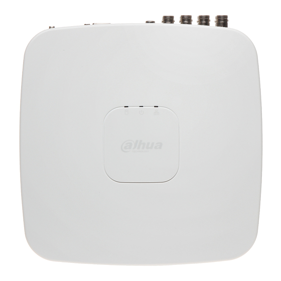
Видеорегистратор Dahua DHI-XVR4104C
Инструкции и ПО
Инструкции и ПО
ОбзорОтзывыИнструкции и ПО
Основная инструкция по настройке (.pdf)
Программное обеспечение для видеорегистратора Dahua DHI-XVR4104C
ПО CMS SmartPSS v.1.11.1 для Windows (.zip)
Приложение iDMSS Lite для iPhone
Приложение iDMSS HD Lite для iPad
Приложение gDMSS Lite для смартфонов Android
Приложение gDMSS HD Lite для планшетов Android
Для ознакомления с инструкцией необходимо нажать на ссылку «ЗАГРУЗИТЬ», чтобы скачать pdf файл. Если есть кнопка «ПРОСМОТР», то можно просто посмотреть документ онлайн.
Для удобства, Вы можете сохранить данную страницу с файлом руководства по эксплуатации в свой список «избранное» прямо на сайте (доступно для зарегистрированных пользователей).
Смотрите инструкцию для похожих моделей:

Вы можете задать вопрос посетителям сайта по модели DAHUA DH-XVR4104C-X1. Если Вы являетесь её пользователем, то пожалуйста оставьте, по возможности развёрнутый отзыв:
Имя:
E-mail:
Телефон:
Вопрос:
Задать вопрос
Ваш вопрос отправлен. Мы свяжемся с Вами в ближайшее время.
Пожалуйста, заполните все поля.
Некорректный адрес E-Mail.
Произошла ошибка. Повторите попытку позже.
инструкцияDahua Technology XVR4104C-X1

Digital Video Recorder
User’s Manual
5.0 ZHEJIANG DAHUA VISION TECHNOLOGY CO., LTD.
Посмотреть инструкция для Dahua Technology XVR4104C-X1 бесплатно. Руководство относится к категории диктофоны, 1 человек(а) дали ему среднюю оценку 9.2. Руководство доступно на следующих языках: английский. У вас есть вопрос о Dahua Technology XVR4104C-X1 или вам нужна помощь? Задайте свой вопрос здесь
- Foreword
- Important Safeguards and Warnings
- 1 Introduction
- 2 Getting Started
- 3 The Grand Tour
- 4 Connecting Basics
- 5 Local Configurations
- 6 Web Operations
- 7 FAQ
- Appendix 1 Glossary
- Appendix 2 HDD Capacity Calculation
- Appendix 3 Compatible Backup Devices
- Appendix 4 Compatible CD/DVD Burner List
- Appendix 5 Compatible Displayer List
- Appendix 6 Compatible Switcher
- Appendix 7 Earthing
- Appendix 8 RJ45-RS-232 Connection Cable Definition
- Appendix 9 Cybersecurity Recommendations

Главная
| Dahua Technology | |
| XVR4104C-X1 | XVR4104C-X1 | |
| диктофон | |
| английский | |
| Руководство пользователя (PDF), Краткое руководство пользователя (PDF), Техническая спецификация (PDF) |
Процессор
Порты и интерфейсы
| Входные видео каналы | 4 канала |
| Входные порты BNC | 4 |
| Вход аудио | 1 |
| Выход аудио | 1 |
| Количество HDMI портов | 1 |
| Количество выходов VGA (D-Sub) | 1 |
| Количество портов USB 2.0 | 2 |
Сеть
| Подключение Ethernet | Да |
| Тип Ethernet интерфейса | Быстрый Ethernet |
| Количество портов Ethernet LAN ( RJ-45) | 1 |
| Число пользователей | 128 пользов. |
| Поддерживаемые сетевые протоколы | HTTP, HTTPS, TCP/IP, IPv4/IPv6, 3G/4G, UPnP, RTSP, UDP, SMTP, NTP, DHCP, DNS, IP Filter, PPPoE, DDNS, FTP, Alarm Server, P2P, IP Search |
Производительность
| Форматы сжатия видео | H.264, H.264+, H.265, H.265+ |
| Поддерживаемые форматы аудио | AAC, G.711 A-law, G.711 μ-law, PCM |
| Цвет товара | Белый |
| Поддерживаемые разрешения воспроизведения | 1920×1080, 1280×1024, 1280×720 |
| Поддержка Multi-display | Да |
| режимы мульти-дисплея | 4, 6 |
| Видео обнаружение движения | Да |
| Обнаружение потери видеосигнала | Да |
| PTZ-контроль | Да |
| Режимы воспроизведения | Fast, Next, Pause, Play, Previous, Repeat, Shuffle, Slow, Stop, Zoom |
| Подключение к USB | Да |
| Функция паузы | Да |
| Сертификация | FCC: Part 15 Subpart BnCE: CE-LVD: EN 60950-1/IEC 60950-1nCE-EMC: EN 61000-3-2, EN 61000-3-3, EN 55032, EN 50130, EN 55024 |
| Емкость стойки | 1U |
| Максимальная частота кадров | 30 fps |
| Скорость цифрового потока | 4096 кбит/с |
| Установленная операционная система | Встроенный LINUX |
| Система аналогового формата сигнала | NTSC, PAL |
Жесткий диск
| Количество поддерживаемых жестких дисков | 1 |
| Интерфейс жесткого диска | SATA |
| Максимальная емкость жесткого диска | 6000 GB |
Энергопитание
| Тип подачи питания | Постоянный ток |
| Постоянное напряжение | 12 V |
| Потребляемая мощность (в обычном режиме) | 10 W |
Вес и размеры
| Ширина | 205 mm |
| Глубина | 211 mm |
| Высота | 45 mm |
| Вес | 470 g |
Данные об упаковке
Условия эксплуатации
| Диапазон температур при эксплуатации | -10 — 45 °C |
| Диапазон относительной влажности при эксплуатации | 10 — 90 % |
| Диапазон температур при хранении | -20 — 70 °C |
| Диапазон относительной влажности при хранении | 0 — 90 % |
показать больше
Не можете найти ответ на свой вопрос в руководстве? Вы можете найти ответ на свой вопрос ниже, в разделе часто задаваемых вопросов о Dahua Technology XVR4104C-X1.
Какой вес Dahua Technology XVR4104C-X1?
Какие сертификаты Dahua Technology XVR4104C-X1 имеет?
Какая высота Dahua Technology XVR4104C-X1?
Какая ширина Dahua Technology XVR4104C-X1?
Какая толщина Dahua Technology XVR4104C-X1?
Инструкция Dahua Technology XVR4104C-X1 доступно в русский?
Не нашли свой вопрос? Задайте свой вопрос здесь
-
Contents
Table of Contents -
Bookmarks
Quick Links
DIGITAL VIDEO RECORDER
User’s Manual
V1.1.0
ZHEJIANG DAHUA VISION TECHNOLOGY CO., LTD.
Related Manuals for Dahua DH-XVR4104C-X
Summary of Contents for Dahua DH-XVR4104C-X
-
Page 1: Digital Video Recorder
DIGITAL VIDEO RECORDER User’s Manual V1.1.0 ZHEJIANG DAHUA VISION TECHNOLOGY CO., LTD.
-
Page 2: Cybersecurity Recommendations
Cybersecurity Recommendations Mandatory actions to be taken towards cybersecurity 1. Change Passwords and Use Strong Passwords: The number one reason systems get “hacked” is due to having weak or default passwords. It is recommended to change default passwords immediately and choose a strong password whenever possible.
-
Page 3
In the event that your social media, bank, email, etc. account is compromised, you would not want someone collecting those passwords and trying them out on your video surveillance system. Using a different username and password for your security system will make it more difficult for someone to guess their way into your system. -
Page 4: Foreword
Foreword General This user’s manual (hereinafter referred to be «the Manual») introduces the functions and operations of the DVR devices (hereinafter referred to be «the Device»). Models Series Models DH-XVR4104C-X/DH-XVR4108C-X/DH-XVR4116HS-X/DH-XVR4104HS-X/ XVR4 series DH-XVR4108HS-X/DH-XVR4216AN-X/DH-XVR4232AN-X DH-XVR5108C-X/DH-XVR5104C-4KL-X/DH-XVR5104C-X/DH-XVR5108H-X/ DH-XVR5116H-X/DH-XVR5104H-4KL-X/DH-XVR5108H-4KL-X/ DH-XVR5116H-4KL-X/DH-XVR5108HE-X/DH-XVR5116HE-X/ DH-XVR5108HS-X/DH-XVR5116HS-X/DH-XVR5104HS-4KL-X/ XVR5 series DH-XVR5108HS-4KL-X/DH-XVR5104HS-X/DH-XVR5104H-X/…
-
Page 5: Revision History
Signal Words Meaning Provides additional information as the emphasis and supplement to the text. Revision History Version Revision Content Release Time V1.0.0 First Release. February 27, 2018 V1.0.1 Add eight models. March 27, 2018 1. Add four models. 2. Add following sections: …
-
Page 6
contact the customer service for the latest program and supplementary documentation. There still might be deviation in technical data, functions and operations description, or errors in print. If there is any doubt or dispute, please refer to our final explanation. … -
Page 7: Important Safeguards And Warnings
Important Safeguards and Warnings This Chapter describes the contents covering proper handling of the Device, hazard prevention, and prevention of property damage. Read these contents carefully before using the Device, comply with them when using, and keep it well for future reference. Operation Requirement …
-
Page 8: Table Of Contents
1 Introduction ……………………….1 1.1 Overview ……………………….1 1.2 Functions ……………………….1 2 Getting Started ……………………….3 2.1 Checking the Components………………….3 2.2 Installing HDD ……………………..3 2.2.1 DH-XVR5108C-X/DH-XVR5104C-4KL-X/DH-XVR5104C-X/ DH-XVR4104C-X/DH-XVR4108C-X……………….. 4 2.2.2 DH-XVR7104E-4KL-X/DH-XVR7108E-4KL-X/DH-XVR7104E-4KL-B-X/ DH-XVR7108E-4KL-B-X ………………….5 2.2.3 DH-XVR4116HS-X/DH-XVR5108HS-X/DH-XVR5116HS-X/DH-XVR5104HS-4KL-X/ DH-XVR5108HS-4KL-X/ DH-XVR5108H-X/DH-XVR5116H-X/DH-XVR5104H-4KL-X/DH-XVR5108H-4KL-X/DH-XVR511 6H-4KL-X/DH-XVR5108HE-X/DH-XVR5116HE-X/DH-XVR7104HE-4KL-X/DH-XVR7108HE-4K L-X/DH-XVR7116HE-4KL-X/DH-XVR7108HE-4K-X/DH-XVR5104HS-X/ DH-XVR4104HS-X/DH-XVR5104H-X/DH-XVR5104HE-X/DH-XVR4108HS-X ……
-
Page 9
3.1.7 DH-XVR7416L-4KL-X ………………….. 14 3.1.8 DH-XVR7816S-4KL-X …………………. 14 3.1.9 DH-XVR5432L-X ………………….14 3.1.10 DH-XVR5832S-X ………………….15 3.2 Rear Panel ……………………..16 3.2.1 DH-XVR5108C-X/DH-XVR5104C-4KL-X/DH-XVR5104C-X/ DH-XVR4104C-X/DH-XVR4108C-X………………16 3.2.2 DH-XVR7104E-4KL-X/DH-XVR7108E-4KL-X/DH-XVR7104E-4KL-B-X/ DH-XVR7108E-4KL-B-X ………………….17 3.2.3 DH-XVR4116HS-X/DH-XVR5108HS-X/DH-XVR5116HS-X/DH-XVR5104HS-4KL-X/ DH-XVR5108HS-4KL-X/DH-XVR5104HS-X/ DH-XVR4104HS-X/DH-XVR4108HS-X …. 18 3.2.4 DH-XVR5108H-X/DH-XVR5116H-X/DH-XVR5104H-4KL-X/DH-XVR5108H-4KL-X/ DH-XVR5116H-4KL-X/DH-XVR5108HE-X/DH-XVR5116HE-X/DH-XVR7104HE-4KL-X/DH-XV R7108HE-4KL-X/DH-XVR7116HE-4KL-X/DH-XVR7108HE-4K-X/DH-XVR5104H-X/DH-XVR51 04HE-X/DH-XVR5108H-4KL-X-8P ……………….. -
Page 10
5.2.6 Live View Display ………………….73 5.2.7 Configuring Tour Settings ………………..78 5.3 Entering Main Menu ……………………81 5.4 Controlling PTZ Cameras ………………….84 5.4.1 Configuring PTZ Connection Settings …………….84 5.4.2 Working with PTZ Control Panel ………………86 5.4.3 Configuring PTZ Functions ………………..88 5.4.4 Calling PTZ Functions …………………. -
Page 11
5.12.1 Configuring Face Detection Settings …………….183 5.12.2 Searching for Detected Faces ………………186 5.12.3 Playing the Detected Faces………………188 5.13 IoT Function ……………………..188 5.13.1 Configuring Sensor Settings ………………188 5.13.2 Configuring Temperature and Humidity Camera …………196 5.13.3 Configuring Wireless Siren ………………. 208 5.14 Configuring POS Settings ………………….. -
Page 12
6 Web Operations ……………………..281 6.1 Connecting to Network ………………….281 6.2 Logging in the Web ……………………281 6.3 Resetting Password ……………………282 6.4 Introducing Web Main Menu ………………… 286 7 FAQ …………………………288 Appendix 1 Glossary ……………………..294 Appendix 2 HDD Capacity Calculation ……………….. -
Page 13: Introduction
Introduction Overview The Device is an excellent digital monitor product for security industry. The embedded LINUX OS assures the stable operation. The H.265 and G.711 technologies assure the high quality image and low bit stream. The frame-by-frame play function displays more details for analysis, and provides the functions such as record, playback, and monitor and assures the synchronization for audio and video.
-
Page 14
Support multiple-channel audio and video signal. An independent hardware decodes the audio and video signal from each channel to maintain video and audio synchronization. Backup Function Support backup operation through USB port (such as USB storage disk, portable HDD, and burner). -
Page 15: Getting Started
Getting Started Checking the Components When you receive the Device, please check against the following checking list. If any of the items are missing or damaged, contact the local retailer or after-sales engineer immediately. Sequence Checking items Requirement Appearance No obvious damage. Package No broken or distorted positions that Packing materials…
-
Page 16: Dh-Xvr5108C-X/Dh-Xvr5104C-4Kl-X/Dh-Xvr5104C-X
2.2.1 DH-XVR5108C-X/DH-XVR5104C-4KL-X/DH-XVR5104C-X/ DH-XVR4104C-X/DH-XVR4108C-X 1. Remove the screws to take 2. Fix the screws on the HDD 3. Match the screws with off the cover. but do not fasten them. the holes on the DVR to place the HDD. 4. Turn the DVR upside down 5.
-
Page 17: Dh-Xvr7108E-4Kl-B-X
2.2.2 DH-XVR7104E-4KL-X/DH-XVR7108E-4KL-X/DH-XVR7104E- 4KL-B-X/ DH-XVR7108E-4KL-B-X 2.2.2.1 Installing Battery The battery is only provided with some models. 1. Put the battery cable through the hole. 2. Connect to the cable into the port. 2.2.2.2 Installing HDD Skip step 6 if the battery is not equipped with the model you purchased. 1.
-
Page 18: 4Kl-X/Dh-Xvr5108He-X/Dh-Xvr5116He-X/Dh-Xvr7104He-4Kl-X/Dh-Xvr7108He-4K L-X/Dh-Xvr7116He-4Kl-X/Dh-Xvr7108He-4K-X/Dh-Xvr5104Hs-X/ Dh-Xvr4104Hs-X/Dh-Xvr5104H-X/Dh-Xvr5104He-X/Dh-Xvr4108Hs-X
7. Use the HDD cable and 8. Install the bracket back and 9. Put back the cover and power cable to connect then fasten the screws. fasten the screws. HDD and mainboard. 2.2.3 DH-XVR4116HS-X/DH-XVR5108HS-X/DH-XVR5116HS-X/DH -XVR5104HS-4KL-X/DH-XVR5108HS-4KL-X/ DH-XVR5108H-X/DH-XVR5116H-X/DH-XVR5104H-4KL-X/DH-XVR 5108H-4KL-X/DH-XVR5116H-4KL-X/DH-XVR5108HE-X/DH-XVR51 16HE-X/DH-XVR7104HE-4KL-X/DH-XVR7108HE-4KL-X/DH-XVR7 116HE-4KL-X/DH-XVR7108HE-4K-X/DH-XVR5104HS-X/ DH-XVR4104HS-X/DH-XVR5104H-X/DH-XVR5104HE-X/DH-XVR4 108HS-X 1.
-
Page 19: Dh-Xvr4216An-X/Dh-Xvr4232An-X/Dh-Xvr5216An-X/Dh-Xvr5232An-X/ Dh-Xvr5208An-4Kl-X/Dh-Xvr5216An-4Kl-X/Dh-Xvr5216A-X/Dh-Xvr7208A-4Kl-X/Dh- Xvr7216A-4Kl-X/Dh-Xvr7208A-4K-X
device and fix the screws. 2.2.4 DH-XVR4216AN-X/DH-XVR4232AN-X/DH-XVR5216AN-X/D H-XVR5232AN-X/DH-XVR5208AN-4KL-X/DH-XVR5216AN-4KL-X/ DH-XVR5216A-X/DH-XVR7208A-4KL-X/DH-XVR7216A-4KL-X/DH- XVR7208A-4K-X 1. Remove the screws on the 2. Fix the screws onto the 3. Put the HDD into the cover. HDD, but do not be Device. fastened. 4. Turn the device to see the 5.
-
Page 20: Dh-Xvr7816S-4Kl-X/Dh-Xvr5832S-X
4. Connect the other end of 5. Use the power cable to 6. Put back the cover and fix HDD cable to the connect HDD and the screws. mainboard. mainboard. 2.2.6 DH-XVR7816S-4KL-X/DH-XVR5832S-X 1. Loose the screws on the 2. Fix the HDD(s) onto the 3.
-
Page 21
If you want to install more accessories to the rack, take preventive measures to avoid power socket overload. Step 4 Install more accessories to the rack if needed. Getting Started 9… -
Page 22: The Grand Tour
The Grand Tour This chapter introduces various components of the Device, remote control and mouse operations. Front Panel 3.1.1 DH-XVR5108C-X/DH-XVR5104C-4KL-X/DH-XVR5104C-X/ DH-XVR4104C-X/DH-XVR4108C-X Figure 3-1 Icon Name Function The indicator is off when the HDD is running normally. HDD status indicator The indicator glows blue when the HDD is in …
-
Page 23: Dh-Xvr7108E-4Kl-B-X
3.1.2 DH-XVR7104E-4KL-X/DH-XVR7108E-4KL-X/DH-XVR7104E- 4KL-B-X/ DH-XVR7108E-4KL-B-X Figure 3-2 Button/Icon Function Turns on/off the DVR. The indicator glows blue when the DVR is POWER turned on. HDD status The indicator glows blue when the HDD is in malfunction. indicator Network status The indicator glows blue when the network connection is indicator abnormal.
-
Page 24: Dh-Xvr5104He-X
3.1.3 DH-XVR5108H-X/DH-XVR5116H-X/DH-XVR5104H-4KL-X/D H-XVR5108H-4KL-X/DH-XVR5116H-4KL-X/DH-XVR5108HE-X/DH- XVR5116HE-X/DH-XVR4116HS-X/DH-XVR5108HS-X/DH-XVR511 6HS-X/DH-XVR5104HS-4KL-X/DH-XVR5108HS-4KL-X/ DH-XVR5104HS-X/DH-XVR4104HS-X/DH-XVR4108HS-X/DH-XVR 5104H-X/DH-XVR5104HE-X Figure 3-3 Port Name Function Glows blue when HDD status is abnormal. Glows blue when network status is abnormal. POWER Glows blue when the power is connected properly. Connects to peripheral devices such as USB storage device, USB port keyboard and mouse.
-
Page 25: Dh-Xvr4216An-X/Dh-Xvr4232An-X/Dh-Xvr5216An-X/Dh-Xvr5232An-X/ Dh-Xvr5208An-4Kl-X/Dh-Xvr5216An-4Kl-X/Dh-Xvr5216A-X
3.1.5 DH-XVR4216AN-X/DH-XVR4232AN-X/DH-XVR5216AN-X/D H-XVR5232AN-X/DH-XVR5208AN-4KL-X/DH-XVR5216AN-4KL-X/ DH-XVR5216A-X Figure 3-5 Port Name Function Status indicator light Glows blue when the device is working properly. Glows blue when HDD status is abnormal. Glows blue when network status is abnormal. POWER Glows blue when the power is connected properly. Connects to the external devices such as keyboard, mouse, USB port and USB storage device.
-
Page 26: Dh-Xvr7416L-4Kl-X
3.1.7 DH-XVR7416L-4KL-X Figure 3-7 Port Name Function IR receiver Receives infrared signal from remote control. Connects to peripheral devices such as USB storage USB port device, keyboard and mouse. Table 3-7 3.1.8 DH-XVR7816S-4KL-X Figure 3-8 Port Name Function IR receiver Receives infrared signal from remote control.
-
Page 27: Dh-Xvr5832S-X
Port Name Function Status indicator light Glows blue when the device is working properly. Glows blue when HDD status is abnormal. Glows blue when network status is abnormal. POWER Glows blue when the power is connected properly. Connects to peripheral devices such as USB storage USB port device, keyboard and mouse.
-
Page 28: Rear Panel
Rear Panel 3.2.1 DH-XVR5108C-X/DH-XVR5104C-4KL-X/DH-XVR5104C-X/ DH-XVR4104C-X/DH-XVR4108C-X Figure 3-11 Port Name Function Video input port Connects to analog camera to input video signal. Connects to external devices such as USB storage device, USB port keyboard and mouse. Outputs analog video data to the connected display with VGA VGA port port.
-
Page 29: Dh-Xvr7108E-4Kl-B-X
3.2.2 DH-XVR7104E-4KL-X/DH-XVR7108E-4KL-X/DH-XVR7104E- 4KL-B-X/ DH-XVR7108E-4KL-B-X Figure 3-12 Figure 3-13 Port Name Function Video input port Connects to analog camera to input video signal. Receives audio signal output from the devices such as Audio input port microphone. Outputs audio signal to the devices such as the sound box. Audio output port RS485 Connects to the control devices such as speed dome PTZ.
-
Page 30: Dh-Xvr4116Hs-X/Dh-Xvr5108Hs-X/Dh-Xvr5116Hs-X/Dh-Xvr5104Hs-4Kl-X/ Dh-Xvr5108Hs-4Kl-X/Dh-Xvr5104Hs-X/ Dh-Xvr4104Hs-X/Dh-Xvr4108Hs-X
Port Name Function Power input port Inputs DC 12V power. Power output port Outputs DC 12V power. Ground Ground terminal. Table 3-12 3.2.3 DH-XVR4116HS-X/DH-XVR5108HS-X/DH-XVR5116HS-X/DH -XVR5104HS-4KL-X/DH-XVR5108HS-4KL-X/DH-XVR5104HS-X/ DH-XVR4104HS-X/DH-XVR4108HS-X Figure 3-14 Port Name Function Video input port Connects to analog camera to input video signal. Receives audio signal output from the devices such as Audio input port microphone.
-
Page 31: 04He-X/Dh-Xvr5108H-4Kl-X-8P
3.2.4 DH-XVR5108H-X/DH-XVR5116H-X/DH-XVR5104H-4KL-X/D H-XVR5108H-4KL-X/DH-XVR5116H-4KL-X/DH-XVR5108HE-X/DH- XVR5116HE-X/DH-XVR7104HE-4KL-X/DH-XVR7108HE-4KL-X/DH -XVR7116HE-4KL-X/DH-XVR7108HE-4K-X/DH-XVR5104H-X/DH-X VR5104HE-X/DH-XVR5108H-4KL-X-8P Figure 3-15 Port Name Function 4 groups of alarm input ports (Group 1: port 1 to port 4; Group 2: port 5 to port 8; Group 3: port 9 to port 12; Group 4: port 13 to port 16).
-
Page 32: Xvr7216A-4Kl-X/Dh-Xvr7208A-4K-X/Dh-5208An-4Kl-X-8/Dh-5216An-4Kl-X-16P
Port Name Function High definition audio and video signal output port. The port outputs the uncompressed high definition video and HDMI port multi-channel audio data to the connected display with HDMI port. Connects to external devices such as USB storage device, USB port keyboard and mouse.
-
Page 33
Port Name Function 4 groups of alarm input ports (Group 1: port 1 to port 4; Group 2: port 5 to port 8; Group 3: port 9 to port 12; Group 4: port 13 to port 16). These ports receive the signal from the external alarm source. -
Page 34: Dh-Xvr7416L-4Kl-X/Dh-Xvr5432L-X
3.2.6 DH-XVR7416L-4KL-X/DH-XVR5432L-X Figure 3-17 Port Name Function Ground terminal. Power input port Inputs power. Power button Turns on/off the DVR. Receives audio signal output from the devices such as Audio input port microphone. Audio input port Tow-way talk input port which receives analog audio signal (MIC IN) output from the devices such as microphone and pickup.
-
Page 35: Dh-Xvr7816S-4Kl-X/Dh-Xvr5832S-X
Port Name Function Connects to the control devices such as speed dome PTZ. RS485 RS485_A port is connected by the cable A and RS485_B is communication port connected to the cable B. Four-wire Four-wire full-duplex 485 port. T+ and T- is the output wire; R+ full-duplex 485 port and R- is the input wire.
-
Page 36
Port Name Function Receives the analog audio signal output from the devices such Audio input port as microphone. Audio input port Tow-way talk input port which receives the analog audio signal (MIC IN) output from the devices such as microphone, pickup. Audio output port Tow-way talk output port which outputs the analog audio signal to (MIC OUT) -
Page 37: Remote Control Operations
Port Name Function RS232 debug It is for general COM debug to configure IP address or transfer COM. transparent COM data. High definition audio and video signal output port. It outputs the same video source as VGA. It supports 4K resolution output and HDMI port supports mouse operation and control.
-
Page 38
Name Function Forward Multi-step forward speed and normal speed playback. Slow motion Multi-step slow motion speed or normal playback. Next record In playback state, press this button to play back the next video. In playback state, press this button to play back the previous Previous record video. -
Page 39: Mouse Operations
Mouse Operations The operations are based on the considerations for right-handed users. Operation Function Password input dialogue box pops up if you have not logged in yet. In live view window interface, you can go to the main menu. When you have selected one menu item, click it to view menu content. Implement the control operation.
-
Page 40
Operation Function selection with left mouse Select privacy mask zone. button Table 3-19 The Grand Tour 28… -
Page 41: Connecting Basics
Connecting Basics This chapter introduces the typical connection diagrams and ports connections. Typical Connection Diagram The following figure is for reference only. The actual product shall govern. Figure 4-1 Connecting Basics 29…
-
Page 42
Figure 4-2 Connecting Basics 30… -
Page 43: Connecting To Video And Audio Input And Output
Connecting to Video and Audio Input and Output 4.2.1 Video Input The video input interface is BNC. The input video format includes: PAL/NTSC BNC (1.0V 75Ω). The video signal should comply with your national standards. The input video signal shall have high SNR, low distortion; low interference, natural color and suitable lightness.
-
Page 44: Audio Input
4.2.3 Audio Input These series products audio input port adopt BNC port. Due to high impedance of audio input, please use active sound pick-up. Audio transmission is similar to video transmission. Try to avoid interference, dry joint, loose contact and it shall be away from high tension current. 4.2.4 Audio Output The audio output signal parameter is usually over 200mv 1KΩ…
-
Page 45: Introducing Alarm Port
Please make sure the front-end device has soundly earthed Improper grounding may result in chip damage. 4.3.1 Introducing Alarm Port The alarm input ports are dependent on the model you purchased. Figure 4-3 Icon Description 1,2,3,4,5,6, ALARM 1 to ALARM 16. The alarm becomes active in low voltage. 7,8,9,10,11,…
-
Page 46: Alarm Output
Use the same ground with that of DVR if you use external power to the alarm device. Figure 4-4 4.3.3 Alarm Output Provide external power to external alarm device. To avoid overloading, please read the following relay parameters table carefully. …
-
Page 47: Connecting To Rs485 Port
Connecting to RS485 Port Step 1 Connect the RS485 cable of the PTZ camera to the RS485 port on the Device. Ensure the match of A and B interfaces. Step 2 Connect the video out cable of the PTZ camera to the video input port on the Device. Step 3 Turn on the PTZ camera.
-
Page 48: Local Configurations
Local Configurations Please read the following notes prior to using the Device. The interfaces in the Manual are used for introducing the operations and only for reference. The actual interface might be different dependent on the model you purchased. If there is inconsistency between the Manual and the actual product, the actual product shall govern.
-
Page 49
To secure the Device, it is strongly recommended for you to properly keep the password for admin and modify it regularly. Step 1 Turn on the Device. The Device Initialization interface is displayed. See Figure 5-1. Figure 5-1 Step 2 Configure the password information for admin. -
Page 50
Figure 5-2 Step 4 Draw a unlock pattern. After the setting is completed, the password protection settings interface is displayed. See Figure 5-3. The pattern that you want to set must cross at least four points. If you do not want to configure the unlock pattern, click Skip. … -
Page 51: Resetting Password
Step 5 Configure the protection parameters for password. For details, see Table 5-2. After configuration, if you forgot the password for admin user, you can reset the password through the reserved email address or security questions. For details about resetting the password, see «0 Resetting Password.» If you do not want to configure the settings, disable the email address and security questions functions on the interface.
-
Page 52
Figure 5-4 5.1.3.2 Resetting Password on Local Interface Step 1 Enter the login interface. If you have configured unlock pattern, the unlock pattern login interface is displayed. See Figure 5-5. Click Forgot Pattern, the password login interface is displayed. See Figure 5-6. If you did not configure unlock pattern, the password login interface is displayed. -
Page 53
Figure 5-5 Figure 5-6 Step 2 Click If you did not set the reserved email address, the email entering interface is displayed. See Figure 5-8. Enter the email address, and then click Next, the Prompt message interface is displayed. See Figure 5-7. … -
Page 54
Figure 5-7 Figure 5-8 Step 3 Click OK. The Reset Password interface is displayed. See Figure 5-9. After clicking OK, the system will collects your information for password reset, and the information includes but not limited to email address, MAC address, and device serial number. -
Page 55
Figure 5-9 Step 4 Reset the password. QR code Follow the onscreen instructions to get the security code in your reserved email address. In the Security code box, enter the security code. You can get the security code twice by scanning the same QR code. If you need to get the security code once again, please refresh the interface. -
Page 56
Figure 5-10 Step 5 Click Next. The new password resetting interface is displayed. See Figure 5-11. Figure 5-11 Step 6 In the New Password box, enter the new password and enter it again in the Confirm Password box. Step 7 Click Save. -
Page 57
A pop-up message is displayed asking if you want to sync the password with the remote devices, see Figure 5-12. Click Cancel, the resetting is finished. Click OK, the Sync Info interface is displayed. See Figure 5-12. Figure 5-12 This message appears only when there are digital channels instead of complete analog channels. -
Page 58: Setting Up With The Startup Wizard
5.1.3.3 Using Reset Button on the Mainboard You can always use the reset button on the mainboard to reset the Device to the factory default. Not all models are provided with reset button. Step 1 Disconnect the Device from power source, and then remove the cover panel. For details about removing the cover panel, see «2.2 Installing HDD.»…
-
Page 59: Configuring General Settings
Figure 5-15 If you select the Auto-check for updates check box, the system will notify you automatically when updates are available. After the auto-check function is enabled, to notify you to update timely, the system will collect the information such as IP address, device name, firmware version, and device serial number.
-
Page 60
Figure 5-16 Step 2 Configure the general settings parameters. See Table 5-3. Parameter Description Device Name In the Device Name box, enter the Device name. Device No. In the Device No. box, enter a number for the Device. Language In the Language list, select a language for the Device system. In the Video Standard list, select PAL or NTSC according to your actual Video Standard situation. -
Page 61
5.1.4.3 Configuring Date and Time Settings You can configure the system time, choose the time zone, set the daylight saving time, and enable the NTP server. You can also configure date and time settings by selecting Main Menu > SYSTEM > GENERAL >… -
Page 62
Parameter Description End Time Enable the NTP function to sync the Device time with the NTP server. In the Server box, enter the IP address or domain name of the corresponding NTP server. Server Click Manual Update, the Device starts syncing with the server immediately. -
Page 63
Parameter Description Multi-address: Two Ethernet ports work separately through either of which you can request the Device to provide the services such as HTTP and RTSP. You need to configure a default Ethernet port (usually the Ethernet port 1 by default) to request the services from the device end such as DHCP, Email and FTP. -
Page 64
Parameter Description Alternate DNS In the Alternate DNS box, enter the IP address of alternate DNS. In the MTU box, enter a value for network card. The value ranges from 1280 byte through 1500 byte. The default is 1500. The suggested MTU values are as below. … -
Page 65
After the P2P function is enabled and connected to the Internet, the system will collects your information for remote access, and the information includes but not limited to email address, MAC address, and device serial number. You can start adding the device. … -
Page 66
The interface requiring device initialization is displayed. A pop-up message reminding you to make sure the Device is initialized is displayed. Tap OK. If the Device has not been initialized, Tap Device Initialization to perform initializing by following the onscreen instructions. … -
Page 67
Figure 5-22 Enter a name for the DVR, the username and password, scan the QR code under Device SN. Tap Start Live Preview. The Device is added and displayed on the live view interface of the cell phone. See Figure 5-23. Figure 5-23 Local Configurations 55… -
Page 68
5.1.4.6 Configuring Encode Settings You can configure the settings of main stream and sub stream for the Device. You can also configure encode settings by selecting Main Menu > CAMERA > ENCODE > Encode. Step 1 After you have configured the P2P settings, on the P2P interface, click Next. The Encode interface is displayed. -
Page 69
Parameter Description Configure the frames per second for the video. The higher the value, the clearer and smoother the image will become. Frame rate changes along with the resolution. Frame Rate Generally, in PAL format, you can select the value from 1 through 25; (FPS) in NTSC format, you can select the value from 1 through 30. -
Page 70
Figure 5-25 Step 2 Configure the settings for the snapshot parameters. See Table 5-7. Parameter Description In the Manual Snap list, select how many snapshots you want to take Manual Snap each time. In the Channel list, select the channel that you want to configure the Channel settings for. -
Page 71
Figure 5-26 Step 2 Configure the basic storage settings parameters. See Table 5-8. Parameter Description Configure the settings for the situation when all the read/write discs are full, and there is no more free disc. HDD Full Select Stop Record to stop recording … -
Page 72
Figure 5-27 Step 2 Configure the record settings parameters. See Table 5-9. Parameter Description Channel In the Channel list, select a channel to record the video. In the Pre-record list, enter the amount of time that you want to start Pre-record the recording in advance. -
Page 73
Parameter Description Define a period during which the configured recording setting is active. Period The system only activates the alarm in the defined period. Copy Click Copy to copy the settings to other channels. Table 5-9 Step 3 Define the video recording period by drawing or editing. By default, it is active all the time. -
Page 74
Select the check box of event type, and then click to clear the defined period. When selecting MD&Alarm, the respective check box of MD and Alarm will be cleared. Define the period by editing. Take Sunday as an example. Click The Period interface is displayed. -
Page 75: Live View
Step 1 After you have configured the video recording settings, on the Record interface, click Next. The SNAPSHOT interface is displayed. See Figure 5-31. Figure 5-31 Step 2 Configure the snapshot settings parameters. See Table 5-10. Parameter Description Channel In the Channel list, select a channel to take a snapshot. Select the check box of the event type which includes General, MD, Event type Alarm, MD&Alarm, Intel, and POS.
-
Page 76: Live View Screen
Figure 5-32 5.2.1 Live View Screen You can view the live video from the connected cameras through each channel on the screen. By default, the system time, channel name and channel number are displayed on each channel window. This setting can be configured by selecting Main Menu > CAMERA > OVERLAY.
-
Page 77: Live View Control Bar
5.2.2 Live View Control bar The live view control bar provides you access to perform the operations such as playback, zoom, real-time backup, manual snapshot, voice talk, adding remote devices, and streams switch. When you move the pointer to the top middle position of a channel window, the live view control bar is displayed.
-
Page 78
Function Function Function Instant Play Manual Snap Siren Digital Zoom Mute Audio Talk Real-time White Light Camera Registration Backup Table 5-12 5.2.2.1 Instant Playback You can play back the previous five minutes to sixty minutes of the recorded video. By clicking , the instant playback interface is displayed. -
Page 79: Digital Zoom
5.2.2.2 Digital Zoom You can enlarge a specific area of the image to view the details by either of the following two ways. Click , the icon switches to . Hold down the left mouse button to select the area …
-
Page 80: Navigation Bar
5.2.2.7 Siren (Supported on camera with siren function) Click to manually control the camera to generate alarm sound. 5.2.2.8 Bidirectional Talk (Digital channel only) You can perform the voice interaction between the Device and the remote device to improve efficiency of emergency. This function is supported only when the remotely connected IPC device supports bidirectional talk.
-
Page 81: Shortcut Menu
Icon Function Go to the previous screen. Go to the next screen. Enable tour function. The icon switches to Open the PTZ control panel. For details, see «5.4 Controlling PTZ Cameras.» Open the Color Setting interface. For details, see «5.2.5 Color Setting.»…
-
Page 82
Figure 5-37 Function Description Main Menu Open Main Menu interface. Open the PLAYBACK interface where you can search and play Search back record files. Open the PTZ interface. Configure the live view screen as a single-channel layout or View Layout multi-channel layout. -
Page 83: Color Setting
Function Description Point to the channel window and right-click on it to open the shortcut menu, and then click Auto Focus. Auto Focus Not all cameras support this function. Open the COLOR interface where you can adjust the video image Color Setting color.
-
Page 84
Parameter Description Adjust the sharpness of image edge. The bigger the value is, the Sharpness more obvious the image edge, and the noise is also greater. The value ranges from 1 to 15. The default value is 1. Adjust the hue of image. The value ranges from 0 to 100. The default value is 50. -
Page 85: Live View Display
Parameter Description You can customize four color modes. Click Customized. The Customized Color interface is displayed. In the Color Mode list, select Customized 1, for example. Then configure the settings for sharpness, hue, brightness, Customized contrast and saturation. If you select All, the configuration will applies to all four customized color modes.
-
Page 86
Parameter Description Out Port Indicates the main screen port. Select the Time Title check box, the current system time Time Title displays in each channel window in live view screen. To hide the time, clear the check box. Select the Channel Title check box, the channel name, channel number and recording status display in each channel Channel Title window in live view screen. -
Page 87
5.2.6.2 Configuring Viewing Layout You can configure the view layout in the live view screen. Step 1 Select Main Menu > DISPLAY > VIEW. The View Setting interface is displayed. See Figure 5-40. Figure 5-40 Step 2 Configure the view layout by clicking the layout buttons on the bottom. See Figure 5-41. Figure 5-41 For example, click and select 9-16, the view layout changes immediately, see… -
Page 88
Figure 5-42 Step 3 Adjust the position of channels if needed. In the channel list, for example, in the channel 9 list, you can select 10, and then the channel 9 and channel 10 exchange positions. Step 4 Click Apply to complete the settings. The live view screen displays the same layout as configured in this section. -
Page 89
Figure 5-43 Step 2 Configure the settings for the zero-channel parameters. See Table 5-17. Parameter Description Enable Enable zero-channel function. In the Compression list, select the video compression standard Compression according to the device capability. The default is H.265. In the Resolution list, select the video resolution. The default is Resolution 704×576 (D1). -
Page 90: Configuring Tour Settings
You can adjust the border margins in top, bottom, left and right directions as well as the brightness of the monitor connected to the Video out port of the Device. Step 1 Select Main Menu > DISPLAY > TV ADJUST. The TV ADJUST interface is displayed.
-
Page 91
Figure 5-45 Figure 5-46 Step 2 Configure the settings for the tour parameters for both Main Screen and Extra Screen. See Table 5-18. Local Configurations 79… -
Page 92
Parameter Description Enable Enable tour function. Enter the amount of time that you want each channel group displays Interval (Sec.) on the screen. The value ranges from 5 seconds to 120 seconds, and the default value is 5 seconds. Video Detect, Select the View 1 or View 8 for Motion Detect tour and Alarm Tour Alarm (system alarm events). -
Page 93: Entering Main Menu
Step 2 Select the channels that you want to group for tour. See Figure 5-48. If you want to select more than one channel, in the Window Split list, do not select View 1. Figure 5-48 Step 3 Click OK to complete the settings. Modifying a Channel Group Double-click on a channel group, the Modify Channel Group interface is displayed.
-
Page 94
Figure 5-50 Local Configurations 82… -
Page 95
Description Icon Includes eight function tiles: VIDEO, ALARM, IVS, POS, IoT, AI, BACKUP, DISPLAY, and AUDIO. Click each tile to open the configuration interface of the tile. VIDEO: Search for and play back the recorded video saved on the Device. -
Page 96: Controlling Ptz Cameras
Description Icon Displays Cell Phone Client and Device SN QR Code. Cell Phone Client: Use your mobile phone to scan the QR code to add the device into the Cell Phone Client, and then you can start accessing the Device from your cell phone. Device SN: Obtain the Device SN by scanning the QR code.
-
Page 97
Figure 5-51 Step 2 Configure the settings for the PTZ connection parameters. See Table 5-20. Parameter Description In the Channel list, select the channel that you want to connect the PTZ Channel camera to. Local: Connect through RS485 port or coaxial cable. PTZ Type Remote: Connect through network by adding IP address of PTZ … -
Page 98: Working With Ptz Control Panel
Step 3 Click Apply to save the settings. Click Copy to copy the settings to other channels. 5.4.2 Working with PTZ Control Panel PTZ control panel performs the operations such as directing camera in eight directions, adjusting zoom, focus and iris settings, and quick positioning. Basic PTZ Control Panel Right-click on the live view screen and then select PTZ.
-
Page 99
Parameter Description Dragging upward is to zoom out, and dragging downward is to zoom in. The smaller the square, the larger the zoom effect. Not all models support this function and can only be controlled through mouse operations. Click , you can control the four directions (left, right, up, and down) PTZ movement through mouse operation. -
Page 100: Configuring Ptz Functions
5.4.3 Configuring PTZ Functions 5.4.3.1 Configuring Presets Step 1 On the Expanded PTZ Control Panel, click The Preset interface is displayed. See Figure 5-54. Figure 5-54 Step 2 Click the direction arrows to the required position. Step 3 In the Preset box, enter the value to represent the required position. Step 4 Click Setting to complete the preset settings.
-
Page 101
Step 4 In the Preset box, enter the preset value. Step 5 Click Add Preset. A preset will be added for this tour. You can repeat adding more presets. Click Del Preset to delete the preset for this tour. This operation can be repeated to delete more presets. -
Page 102: Calling Ptz Functions
Figure 5-57 Step 3 Click the direction arrows to position the left and right borders. 5.4.4 Calling PTZ Functions After you have configured the PTZ settings, you can call the PTZ functions for monitoring from the Expanded PTZ Control Panel. See Figure 5-58. Figure 5-58 5.4.4.1 Calling Presets Step 1…
-
Page 103: Calling Osd Menu
5.4.4.3 Calling Patterns Step 1 On the Expanded PTZ Control Panel, in the No. box, enter the value of the pattern that you want to call. Step 2 Call to call the pattern. The PTZ camera moves according to the configured pattern repeatedly. Step 3 Click again to stop calling the pattern.
-
Page 104: Configuring Camera Settings
Step 1 On the Expanded PTZ Control Panel, click The MENU OPERATION interface is displayed. See Figure 5-60. Figure 5-60 Step 2 Click Enter. The OSD menu is displayed. See Figure 5-61. Figure 5-61 Step 3 On the MENU OPERATION interface, click the arrow button to select the onscreen parameters.
-
Page 105
Figure 5-62 Figure 5-63 Step 2 Configure the settings for the image parameters. See Table 5-23. On the digital channel interface, click More Setting to display more parameters. Local Configurations 93… -
Page 106
Parameter Description Channel In the Channel list, select the channel that you want to configure. In the Cable Type list, select the cable type that the camera uses. Cable Type Not all models support this function. In the Period list, select a time period for the image settings. The Period image settings will be only used during the selected period. -
Page 107: Configuring Encode Settings
Parameter Description Enable the function, the left and right side of the video image will be Mirror switched. It is disabled by default. This function specially applies to the image which frame rate is configured as 2 at least. It reduces the noises by making use of the 3D Denoise information between two frames.
-
Page 108
Figure 5-64 Step 2 Configure the settings for the main/sub streams parameters. See Table 5-24. Parameter Description In the Channel list, select the channel that you want to configure the Channel settings for. Enable the smart codec function. This function can reduce the video Smart Codec bit stream for non-important recorded video to maximize the storage space. -
Page 109: Configuring Snapshot Settings
Parameter Description Configure the frames per second for the video. The higher the value, the clearer and smoother the image will become. Frame rate changes along with the resolution. Frame Rate Generally, in PAL format, you can select the value from 1 through 25; (FPS) in NTSC format, you can select the value from 1 through 30.
-
Page 110: Configuring Overlay Settings
Figure 5-65 Step 2 Configure the settings for the snapshot parameters. See Table 5-25. Parameter Description In the Manual Snap list, select how many snapshots you want to take Manual Snap each time. In the Channel list, select the channel that you want to configure the Channel settings for.
-
Page 111: Configuring Covered Area Settings
Figure 5-66 Step 2 Configure the settings for the text overlay parameters. See Table 5-26. Parameter Description In the Channel list, select the channel that you want to configure the Channel settings for. Select the Time Display check box to display the system time on Time Display each channel window in the live view screen.
-
Page 112: Configuring Channel Type
Figure 5-67 Step 2 Configure the settings for the covered area parameters. See Table 5-27. Parameter Description In the Channel list, select the channel that you want to configure the Channel settings for. Preview: Select the Preview check box to apply the configured covered block to the selected channel window in the live view Preview screen.
-
Page 113: Upgrading Coaxial Camera
The CHANNEL TYPE interface is displayed. See Figure 5-68. Figure 5-68 Step 2 Configure the channels. Analog Channel: Select the transmission medium such as CVI, CVBS, and then follow the onscreen instructions to complete the settings. IP Channel: The Device provides expanded IP channels for your use. For example, …
-
Page 114: Configuring Remote Devices
Figure 5-69 Step 2 Click Browse. The Browse interface is displayed. Step 3 Select the upgrade file and then click OK. The COAXIAL UPGRADE interface is displayed. You need to insert the USB storage device that contains the upgrading files. Step 4 Select the check box of the channel that you want to upgrade.
-
Page 115
Figure 5-70 Parameter Description Enable the Uninitialized function, the uninitialized devices out of the Uninitialized searched devices are displayed in the searched device list. Select the uninitialized device from the uninitialized device list, and Initialize the click Initialize to start initializing device. In the Show Filter list, select the remote device type that you want to display in the searched device list. -
Page 116
Parameter Description Add the device by manually configuring settings such as IP address, Manual Add channel selection. For details, see «5.6.1.3 Adding Remote Devices Manually.» Added Device Displays the added devices. You can edit and delete the device, and List view the device information. -
Page 117
Figure 5-72 Step 3 Select the uninitialized device that you want to initialize. Step 4 Click Initialize. The Enter Password interface is displayed. See Figure 5-73. Figure 5-73 Step 5 Configure the password and email information. If you select the Using current device password and email info check box, the remote device automatically uses the current password and email information, so you do not need to set the password and email address again and can go to Step 6. -
Page 118
Figure 5-74 Configure the settings for the password setting parameters. See Table 5-29. Parameter Description User The default is admin. The new password can be set from 8 characters through 32 Password characters and contains at least two types from number, letter and special characters (excluding»‘», «»», «;», «:»… -
Page 119
Figure 5-76 Step 7 Configure the IP address. Select the DHCP check box, you do not need to enter the IP address information, because the system will allocate one IP address to the remote device. Select the STATIC check box, you need to enter the IP address, subnet mast, default gateway, and incremental value. -
Page 120
Figure 5-77 Step 9 Click Finished to complete the settings. 5.6.1.2 Adding Remote Devices Automatically Step 1 On the Registration interface, click Device Search The searched devices are displayed. See Figure 5-78. Figure 5-78 Local Configurations 108… -
Page 121
Step 2 Select the check box of the device. Step 3 Click Add. The device is added into the Added Device area. You can also double-click the device to add it into the Added Device area. You can add devices in batches. 5.6.1.3 Adding Remote Devices Manually Step 1 On the Registration interface, click Manual Add. -
Page 122
Parameter Description your actual situation. If you enter other value, for example, 70, and then you should enter 70 after the IP address when logging in the Device by browser. User Name Enter the user name of the remote device. Password Enter the password of the user for the remote device Enter the remote channel number of the remote device that you want… -
Page 123
Figure 5-80 Step 2 In the Channel list, select the channel that you want to modify settings for. Step 3 Click OK to save the settings. Click Copy to copy the user name and password to other channels. To delete one or more added devices, do the following: … -
Page 124
Figure 5-81 Step 2 Configure the settings for IP address, subnet mask, default gateway, user name, and password. Step 3 Enable the Add function to add the device into the Added Device area. Step 4 Click OK to save the settings. … -
Page 125
5.6.1.6 Exporting IP Address You can export the added IP address to the USB storage device. The exported information is saved in .csv file, which includes IP address, port number, channel number, manufacturer, user name, and password. Step 1 Insert the USB storage device to the USB port of the Device. Step 2 Click Export. -
Page 126: Managing Remote Devices
Figure 5-84 Step 3 Select the file that you want to import. Step 4 Click OK to start importing. After importing is completed, a pop-up message indicating «The import succeeded» is displayed. If the IP address that you want to import already exists in the Device, the system will pop up a message to ask you whether to overwrite the existing content.
-
Page 127
Figure 5-85 5.6.2.2 Viewing Firmware Information You can view the device firmware information such as channel number, IP address, manufacturer, system version, video input, audio input, and alarm in. Select Main Menu > CAMERA > REGISTRATION > Firmware, the Firmware interface is displayed. -
Page 128
Figure 5-86 5.6.2.3 Upgrading Remote Devices Step 1 Select Main Menu > CAMERA > REGISTRATION > Upgrade. The Upgrade interface is displayed. See Figure 5-87. Local Configurations 116… -
Page 129: Configuring Record Settings
Figure 5-87 Step 2 Upgrade the device. File Upgrade Insert a USB storage device containing the upgrade files into the USB port of the Device. Select the devices that you want to upgrade. Click File upgrade. The File Upgrade interface is displayed. Select the upgrading files and click Apply.
-
Page 130: Enabling Record Control
5.7.1 Enabling Record Control Manual recording operation requires the user have the permission to access STORAGE settings. Check to ensure the HDD installed in the Device has been formatted properly. To enter the record control interface, do the following: Step 1 Right-click on the live view screen, the shortcut menu is displayed.
-
Page 131: Configuring Recorded Video Storage Schedule
5.7.2 Configuring Recorded Video Storage Schedule You need to configure the storage schedule for the recorded video so that the recorded video can be saved. For details, see «5.1.4.9 Configuring Recorded Video Storage Schedule.» Configuring Snapshot Settings 5.8.1 Configuring Snapshot Trigger The snapshot is divided into scheduled snapshot, event triggered snapshot, and face detection triggered snapshot.
-
Page 132
Figure 5-90 Step 6 Click Apply to save the settings. If you have configured the snapshot schedule, the configuration has been completed. If you have not configured the snapshot schedule, see «5.1.4.10 Configuring Snapshot Storage Schedule.» 5.8.1.2 Configuring Event Triggered Snapshot Step 1 Select Main Menu >… -
Page 133
Figure 5-91 Step 3 Select Main Menu > ALARM > VIDEO DETECT, and select the event type to configure, for example, select the Motion Detect tab. See Figure 5-92. Local Configurations 121… -
Page 134
Figure 5-92 Step 4 Select the Snapshot check box and select the corresponding channel. Step 5 Click Apply. 5.8.1.3 Configuring Face Detection Triggered Snapshot Step 1 Select Main Menu > CAMERA > ENCODE > Snapshot. The Snapshot interface is displayed. Step 2 In the Mode list, select Human Face, and then configure other parameters. -
Page 135
Figure 5-93 Step 3 Select Main Menu > FACE DETECT > PARAMETERS > Human Face. The Human Face interface is displayed. See Figure 5-94. Figure 5-94 Local Configurations 123… -
Page 136: Configuring Snapshot Storage Schedule
Step 4 Select the Snapshot check box and select the corresponding channel. Step 5 Click Apply. 5.8.2 Configuring Snapshot Storage Schedule You need to configure the storage schedule for the snapshot so that the snapshot can be saved. For details, see «5.1.4.10 Configuring Snapshot Storage Schedule.» 5.8.3 Backing up Snapshots to FTP Step 1 Select Main Menu >…
-
Page 137: Playing Back Video
Playing Back Video 5.9.1 Enabling Record Control Manual recording operation requires the user have the permission to access STORAGE settings. Check to ensure the HDD installed in the Device has been formatted properly. To enter the record control interface, do the following: Step 1 Right-click on the live view screen, the shortcut menu is displayed.
-
Page 138: Instant Playback
5.9.2 Instant Playback You can use the instant playback function to play back the previous five minutes to sixty minutes of the recorded video in any channel. For details about instant playback function, see «5.2.2.1 Instant Playback.» 5.9.3 Main Interface of Video Playback You can search for and play back the recorded video saved on the Device.
-
Page 139
Function Description Display the type and time period of the current recorded video. In the 4-channel layout, there are four time bars are displayed; in the other view layouts, only one time bar is displayed. Click on the colored area to start playback from a certain time. … -
Page 140
Function Description This area includes Mark List and File List. : Click the Mark List button, the marked recorded video list is displayed. Double-click the file to start playing. List Display : Click the File List button, the searched recorded video list is displayed. -
Page 141
Icon Function Previous Frame/Next Frame. When the playback is paused, click or click to play single-frame recorded video. When playing back single-frame recorded video, click start playing forward. Slow Playback. During playing back, click to set the speed of slow playback as SlowX1/2, SlowX1/4, SlowX1/8, or SlowX1/16. -
Page 142: Backing Up Recorded Video
Figure 5-99 From I/O Device: Recorded videos playback from external storage device. See Figure 5-100. Click Browse, select the save path of recorded video file that you want to play. Double-click the video file or click to start playing. Figure 5-100 5.9.3.3 Clipping Recorded Video During playback, clip sections of recorded video and save to the USB storage device.
-
Page 143: Smart Search
Step 1 Select the recorded video file that you want to back up. You can select the following two types of files: Recorded video file: Click , the File List area is displayed. Select the file(s) that you want to back up. …
-
Page 144: Marking And Playing Back Video
Step 4 Click The grid is displayed on the screen. Only single-channel supports smart search. If multi-channels are selected, double-click on the channel window to display this channel only on the screen, and then you can start using smart search function. Step 5 Drag the pointer to select the searching area.
-
Page 145
Step 2 Click The Mark List interface is displayed. See Figure 5-104. Figure 5-104 Step 3 Double-click the file that you want to play back. To search the marked video by time, in the SEARCH box on the top of the interface, enter the time, and then click Playing Back Time before the Mark You can configure to play N seconds of the marked video before the marked time. -
Page 146: Playing Back Snapshots
Figure 5-105 Be default, it manages all the marked videos of the selected channel. To search the marked video, select channel number from the Channel list, enter time in Start Time box and End Time box, and then click Search. All the marked videos display in time order.
-
Page 147: Using The File List
Not all models support this function. Step 1 Select Main Menu > VIDEO, the video search interface is displayed. Step 2 In the Search Type list, select Splice Playback; In the Split Mode list, select 4, 9, or 16. See Figure 5-106. Figure 5-106 Step 3 In the Calendar area, select a date.
-
Page 148
Figure 5-108 Step 4 Start playback. Click , the playback starts from the first file by default. Click any file, the system plays back this file. In the time box on the top of the file list interface, you can enter the specific time to … -
Page 149: Alarm Events Settings
To unlock the recorded video, in the FILE LOCKED interface, select the video, and then click Unlock. See Figure 5-109. Figure 5-109 5.10 Alarm Events Settings 5.10.1 Alarm Information You can search, view and back up the alarm information. Step 1 Select Main Menu >…
-
Page 150: Alarm Input Settings
Figure 5-110 Step 2 In the Type list, select the event type; In the Start Time box and End Time box, enter the specific time. Step 3 Click Search. The search results are displayed. Step 4 Click Backup to back up the search results into the external storage device. Click to play the alarm event.
-
Page 151
Figure 5-111 Step 2 Configure the settings for the local alarms. See Table 5-35. Parameter Description Alarm In Select the channel number. Alarm Name Enter the customized alarm name. Enable Enable or disable the local alarm function. Type In the Type list, select NO or select NC as the voltage output type. Click Setting to display setting interface. -
Page 152
Parameter Description Select the Alarm Upload check box to enable the system to upload the Alarm Upload alarm signal to the network (including alarm center) when an alarm event occurs. Select the Send Email check box to enable the system to send an email notification when an alarm event occurs. -
Page 153
5.10.2.2 Configuring Alarms from Alarm Box You can connect the alarm box to the RS485 port of the Device. When the alarm is detected by the alarm box, the alarm information will be uploaded to the Device, and then the Device outputs the alarms in the way that you configure in this section. -
Page 154
Figure 5-113 Step 2 Configure the alarm input settings from the external IPC. For details, see Table 5-35. Step 3 Click Apply to complete the settings. Click Default to restore the default setting. Click Copy to copy the settings to other channels. … -
Page 155
Figure 5-114 Step 2 Configure the alarm input settings from the external IPC. For details, see Table 5-35. Step 3 Click Apply to complete the settings. Click Default to restore the default setting. Click Copy to copy the settings to other channels. … -
Page 156
Figure 5-115 Step 2 In the Channel list, select a channel or all. Step 3 Click The Setting interface is displayed. See Figure 5-116. Figure 5-116 Step 4 Configure the settings for other parameters of the Alarm Box. For details, see Table 5-35. -
Page 157: Alarm Output Settings
5.10.3 Alarm Output Settings 5.10.3.1 Configuring Alarm Output When the Device activates alarms, the connected alarm device generates alarms in the way that you can configure in this section. You can connect to the output port of the Device or connect wirelessly.
-
Page 158
Step 3 Click Apply to save the settings. 5.10.3.2 Configuring White Light When the motion detection alarm is activated, the system links the camera to generate white light alarm. To use this function, connect at least one white light camera to your Device. Step 1 Select Main Menu >… -
Page 159
5.10.3.3 Configuring Siren When the motion detection alarm is activated, the system links the camera to generate sound alarm. To use this function, connect at least one camera that supports audio function. Step 1 Select Main Menu > ALARM > ALARM OUTPUT > Siren. The Siren interface is displayed. -
Page 160: Video Detection
Step 3 Click Apply to complete the settings. Upgrade Audio File of Camera This function is supported only on the local interface, and not supported on the web. Step 1 Prepare a USB device or other external storage device and plug it into the Device. Step 2 Click Browse.
-
Page 161
Figure 5-121 Step 2 Configure the settings for the motion detection parameters. See Table 5-39. Parameter Description Channel In the Channel list, select a channel to set the motion detection. Region Click Setting to define the motion detection region. Enable MD Enable or disable the motion detection function. -
Page 162
Parameter Description Click Setting to display setting interface. General Alarm: Enable alarm activation through the alarm devices connected to the selected output port. Alarm Out External Alarm: Enable alarm activation through the connected alarm box. Wireless Siren: Enable alarm activation through devices … -
Page 163
Parameter Description Select the check box to enable the function. When an alarm event occurs, the video output port outputs the settings configured in Main Menu > DISPLAY > TOUR. Video Matrix Not all models support this function. Buzzer Select the check box to activate a buzzer noise at the Device. Select the check box to enable the Device to record a local alarm log. -
Page 164
Parameter Description Adjust the threshold for motion detect. Every region of every channel Threshold has an individual threshold. Figure 5-123 When anyone of the four regions activates motion detect alarm, the channel where this region belongs to will activate motion detect alarm. Step 4 Right-click on the screen to exit the region setting interface. -
Page 165: Configuring Video Loss Settings
Click The Period interface is displayed. See Figure 5-125. Figure 5-125 Enter the time frame for the period and select the check box to enable the settings. There are six periods for you to set for each day. Under Copy, select All to apply the settings to all the days of a week, or select specific day(s) that you want to apply the settings to.
-
Page 166
Figure 5-126 To configure the settings for the video loss detection parameters, see “5.10.4.1 Step 2 Configuring Motion Detect Settings.” For PTZ activation, different from motion detection, the video loss detection can activate PTZ preset, tour, and pattern. Step 3 Click Apply to complete the settings. -
Page 167
Figure 5-127 To configure the settings for the tampering detection parameters, see “5.10.4.1 Step 2 Configuring Motion Detect Settings.” For PTZ activation, different from motion detection, the video loss detection can activate PTZ preset, tour, and pattern. Step 3 Click Apply to complete the settings. Click Default to restore the default setting. -
Page 168
Figure 5-128 Step 2 To configure the settings for the diagnosis parameters, see «5.10.4.1 Configuring Motion Detect Settings.» Step 3 Click Apply to complete the settings. Click Default to restore the default setting. Setting the Types for Diagnosing Targets Step 1 Next to Rule, click Setting. -
Page 169: System Events
Parameter Description A horizontal, vertical or diagonal stripe that might appear in the Stripe video because of device aging or electronic interruption. Such stripe brings visual interruption. Video noises such as blurriness or quality reduction that is caused Noise by optical distortion or device problem during camera shooting. Color Cast Variances in the normal proportions of RGB colors.
-
Page 170
Figure 5-130 Step 2 Configure the settings for the HDD event. See Table 5-41. Parameter Description In the Event Type list, select No HDD, HDD Error, or HDD No Space Event Type as the event type. Enable Enable or disable the HDD event detection function. Click Setting to display setting interface. -
Page 171
Parameter Description Select the Send Email check box to enable the system to send an email notification when an alarm event occurs. Send Email To use this function, make sure the email function is enabled in Main Menu > NETWORK > EMAIL. Buzzer Select the check box to activate a buzzer noise at the Device. -
Page 172
Parameter Description Click Setting to display setting interface. General Alarm: Enable alarm activation through the alarm devices connected to the selected output port. Alarm Out External Alarm: Enable alarm activation through the connected alarm box. Wireless Siren: Enable alarm activation through devices … -
Page 173
Figure 5-132 Step 2 Configure the settings for the User event. See Table 5-43. Parameter Description Event Type In the Event Type list, select Illegal Login. Enable the user error detection function. If you do not enable this function, there will be no limit for wrong Enable password entry and the account cannot be locked because of the wrong password. -
Page 174: Configuring Ivs Function
Parameter Description Select the Send Email check box to enable the system to send an email notification when an alarm event occurs. Send Email To use this function, make sure the email function is enabled in Main Menu > NETWORK > EMAIL. Buzzer Select the check box to activate a buzzer noise at the Device.
-
Page 175
Figure 5-133 Step 2 In the Channel list, select the channel number that you want to configure the IVS function. Step 3 Click Add. One line of rule is displayed. See Figure 5-134. Local Configurations 163… -
Page 176
Figure 5-134 Step 4 Configure the parameters for the rule that you selected. Step 5 Select the check box of the rule to enable it. Step 6 Click Apply to complete the settings. 5.11.1.1 Configuring Tripwire Rules When the target object crosses the tripwire in the defined direction, the system activates alarms. -
Page 177
Figure 5-135 Step 2 Draw a tripwire. In the Channel list, select the channel that you want to configure the rules for. Click The monitoring screen to configure the tripwire rules is displayed. See Figure 5-136 for analog camera and the IP camera without preset, and see Figure 5-137 for IP camera with preset. -
Page 178
Figure 5-136 Figure 5-137 Configure the settings for the parameters of drawing rules. See Table 5-44. Parameter Description Name Enter the customized rule name. Set the direction of the tripwire. You can choose A to B (left to Direction right), B to A (right to left), and Both. Local Configurations 166… -
Page 179
Parameter Description Click to draw areas to filter the target. You can configure two filtering targets (maximum size and Filtering Target minimum size). When the target that is crossing the tripwire is smaller than the minimum size or larger than the maximum size, no alarms will be activated. -
Page 180
Parameter Description Click Setting to display setting interface. General Alarm: Enable alarm activation through the alarm devices connected to the selected output port. Alarm Out External Alarm: Enable alarm activation through the connected alarm box. Wireless Siren: Enable alarm activation through devices … -
Page 181
Parameter Description Select the check box to activate a buzzer noise at the Device when Buzzer an alarm event occurs. Select the check box to enable the Device to record a local alarm log when an alarm event occurs. Select the check box to enable audio broadcast in response to an Voice Prompts alarm event. -
Page 182
Step 2 Draw an area. In the Channel list, select the channel that you want to configure the rules for. Click The monitoring screen to configure the intrusion rules is displayed. See Figure 5-140 for analog camera and the IP camera without preset, and see Figure 5-141 for IP camera with preset. -
Page 183
Figure 5-141 Configure the settings for the parameters of drawing rules. See Table 5-46. Parameter Description Name Enter the customized rule name. Configure the actions that are defined as intrusion. You can select Action the Appear check box and the Cross check box. In the Direction list, select the direction of crossing the configured Direction area. -
Page 184
The intrusion detecting function is active. When the target enters and leaves the area, or the target appears in the defined area, the system activates alarms. 5.11.1.3 Configuring Abandoned Rules When the object is placed in the defined detection area for more than the set time, the system activates alarms. -
Page 185
Figure 5-143 Figure 5-144 Configure the settings for the parameters of drawing rules. See Table 5-47. Parameter Description Local Configurations 173… -
Page 186
Parameter Description Name Enter the customized rule name. Configure the minimum time period for activating alarms by Period detecting the abandoned objects. Click to draw areas to filter the target. You can configure two filtering targets (maximum size and Filtering Target minimum size). -
Page 187
Figure 5-145 Step 2 Draw an area. In the Channel list, select the channel that you want to configure the rules for. Click The monitoring screen to configure the missing rules is displayed. See Figure 5-146 for analog camera and the IP camera without preset, and see Figure 5-147 for IP camera with preset. -
Page 188
Figure 5-146 Figure 5-147 Configure the settings for the parameters of drawing rules. See Table 5-48. Parameter Description Local Configurations 176… -
Page 189: Enabling The Intelligent Settings For Ip Camera
Parameter Description Name Enter the customized rule name. Configure the minimum time period for activating alarms by Period detecting the missing objects. Click to draw areas to filter the target. You can configure two filtering targets (maximum size and Filtering Target minimum size).
-
Page 190
Figure 5-148 Step 1 Click SMART PLAN. The SMART PLAN interface is displayed. Step 2 In the Channel list, select the IP camera channel that you have configured the intelligent settings. For the IP camera with preset, see Figure 5-149. … -
Page 191
Figure 5-149 For the IP camera without preset, see Figure 5-150. Figure 5-150 Step 3 Enable the IVS function. Local Configurations 179… -
Page 192: Using Smart Search
For the IP camera with preset, do the following: In the Preset list, select 1_Preset1. All the presets that the IP camera has are displayed in the Preset list, and you just need to select the preset that you have configured the intelligent settings as shown in Figure 5-148.
-
Page 193
Figure 5-152 Step 2 In the Channel list, select the channel that you want to search for the events. Step 3 In the Type list, select the event type that you want to search. Step 4 In the Begin Time box and End Time box, enter the date and time. Step 5 Select the display mode of the search results by clicking Graph or List. -
Page 194
Figure 5-153 Figure 5-154 Step 7 Double-click the video or click Local Configurations 182… -
Page 195: Configuring Face Detection
The video playback interface is displayed. See Figure 5-155. Figure 5-155 Step 8 Click to play back the recorded video. Step 9 Click Back to stop the playback and return to the SMART SEARCH interface. Click Export to export the recorded video files. 5.12 Configuring Face Detection You can configure the face detection settings and search the detected faces in the defined time…
-
Page 196
Figure 5-156 Step 2 Configure the settings for the face detection parameters. See Table 5-49. Parameter Description In the Channel list, select the channel that you want to configure the face detection settings. Channel Only the analog channel 1 supports this function. Enable Enable or disable the face detection function. -
Page 197
Parameter Description Select the Show Message check box to enable a pop-up message Show Message in your local host PC. Select the Alarm Upload check box to enable the system to Alarm Upload upload the alarm signal to the network (including alarm center) when an alarm event occurs. -
Page 198: Searching For Detected Faces
Parameter Description Select to enable audio broadcast in response to a human face Voice Prompts detection event. Table 5-49 Step 3 Click Apply to complete the settings. 5.12.2 Searching for Detected Faces To comply with relevant regulations, the faces have received fuzzy processing. Step 1 Select Main Menu >…
-
Page 199
Figure 5-158 Figure 5-159 Local Configurations 187… -
Page 200: Playing The Detected Faces
5.12.3 Playing the Detected Faces Step 1 On the displayed faces as shown in Figure 5-158, double-click on the face. The VIDEO interface is displayed. See Figure 5-160. Figure 5-160 Step 2 Click to start playing the recorded detected face. Step 3 Click Back to exit the playing interface and return to the faces displaying interface.
-
Page 201
Figure 5-161 Step 2 In the Access Type list, select USB Gateway. Step 3 Click Add. The Add interface is displayed. See Figure 5-162. Figure 5-162 Step 4 Click Pair. The Device starts pairing with the sensor. After pairing is completed, see Figure 5-163. Local Configurations 189… -
Page 202
Figure 5-163 Step 5 Click Back to exit the pairing interface. The added sensor information is displayed. See Figure 5-164. Click to modify the sensor name; click to delete sensor information. Figure 5-164 Local Configurations 190… -
Page 203
5.13.1.2 Connecting Sensor through Camera with Gateway Only the camera with gateway supports this function. Step 1 Select Main Menu > IoT > MANAGER > Sensor Pairing. The Sensor Pairing interface is displayed. See Figure 5-165. Figure 5-165 Step 2 In the Access Type list, select Camera Gateway. -
Page 204
Figure 5-166 Step 5 Click Pair. The Device starts pairing with the sensor. After pairing is completed, see Figure 5-167. Figure 5-167 Step 6 Click Back to exit the pairing interface. The added sensor information is displayed. See Figure 5-168. Click to modify the sensor name;… -
Page 205
Figure 5-168 5.13.1.3 Configuring Alarm Linkage Step 1 Select Main Menu > IoT > MANAGER > Wireless Detector. The Wireless Detector interface is displayed. See Figure 5-169. Local Configurations 193… -
Page 206
Figure 5-169 Step 2 In the Access Type list, select USB, Camera, or All. Step 3 Click The Setting interface is displayed. See Figure 5-116. Figure 5-170 Step 4 Configure the settings for alarm linkage. For details, see Table 5-50. Parameter Description Name… -
Page 207
Parameter Description Click Setting to display setting interface. Define a period during which the motion detection is active. For details, Period see «Setting Motion Detection Period» section in «5.10.4.1 Configuring Motion Detect Settings.» Click Setting to display the PTZ interface. Enable PTZ activation function. -
Page 208: Configuring Temperature And Humidity Camera
Parameter Description Show Message: Select the Show Message check box to enable a pop-up message in your local host PC. Buzzer: Select the check box to activate a buzzer noise at the Device. Video Matrix: Select the check box to enable the function. When …
-
Page 209
Figure 5-171 Step 2 Select the Enable check boxes to enable IoT function. See Figure 5-172. Figure 5-172 Local Configurations 197… -
Page 210
The Device starts detecting the temperature and humidity data from the camera and display on the Realtime Display interface. 5.13.2.2 Viewing Temperature and Humidity Data You can view the temperature and humidity data on the Realtime Display interface after the IoT function is enabled. -
Page 211
Figure 5-174 Step 3 Click Locked to lock the data. The export button is enabled. Step 4 Click Export. The system starts exporting the data. After exporting is finished, a Message dialog box is displayed. Step 5 Click OK. You can find the exported data on your USB device. 5.13.2.4 Configuring Alarm Linkage You can configure alarm linkage settings for temperature and humidity data. -
Page 212
Figure 5-175 Step 2 On the temperature information line, click The Setting interface is displayed. See Figure 5-176. Figure 5-176 Step 3 Configure the settings for alarm linkage. See Table 5-51. Parameter Description Access Point Indicates the channel that the camera is connected to. Local Configurations 200… -
Page 213
Parameter Description Type Temperature by default. Detect Position Set the detect position name. Name Select the channel that you want to preview to help monitor the channel of access point. This channel could be the channel of Preview Channel access point or any other channels according to your actual situation. -
Page 214
Parameter Description Select the channel(s) that you want to record. The selected channel(s) starts recording after an alarm occurs. Record CH The recording for IoT alarms and auto recording function must be enabled. For details, see «5.1.4.9 Configuring Recorded Video Storage Schedule»… -
Page 215
Figure 5-177 Step 2 On the humidity information line, click The Setting interface is displayed. See Figure 5-178. Figure 5-178 Step 3 Configure the settings for the following parameters. See Table 5-52. Parameter Description Access Point Indicates the channel that the camera is connected to. Local Configurations 203… -
Page 216
Parameter Description Type Humidity by default. Detect Position Set the detect position name. Name Select the channel that you want to preview to help monitor the channel of access point. This channel could be the channel of Preview Channel access point or any other channels according to your actual situation. -
Page 217
Parameter Description Select the channel(s) that you want to record. The selected channel(s) starts recording after an alarm occurs. Record CH The recording for IoT alarms and auto recording function must be enabled. For details, see «5.1.4.9 Configuring Recorded Video Storage Schedule»… -
Page 218
Figure 5-179 Step 2 Configure the parameters settings. See Table 5-53. Parameter Description Access Point Indicates the channel that the camera is connected to. Display Type In the Display Type list, select List or Graph. Select the information type that you want to search. You can select Type Humidity or Temperature. -
Page 219
Figure 5-180 For the data displayed in graph, see Figure 5-181. Figure 5-181 Step 4 Click Backup. The system starts exporting the data. Local Configurations 207… -
Page 220: Configuring Wireless Siren
After exporting is finished, a Message dialog box is displayed. Step 5 Click OK. You can find the exported data on your USB device. 5.13.3 Configuring Wireless Siren You can connect the wireless siren to the Device, when there is an alarm event activated on the Device, the wireless siren generate alarms.
-
Page 221: Configuring Pos Settings
5.14 Configuring POS Settings You can connect the Device to the POS (Point of Sale) machine and receive the information from it. This function applies to the scenarios such as supermarket POS machine. After connection is established, the Device can access the POS information and display the overlaid text in the channel window.
-
Page 222: Configuring Pos Settings
5.14.2 Configuring POS Settings Step 1 Select Main Menu > POS > POS SETUP. The POS SETUP interface is displayed. See Figure 5-184. Figure 5-184 Step 2 Configure the settings for the POS parameters. See Table 5-55. Parameter Description In the POS Name list, select the POS machine that you want to configures settings for.
-
Page 223: Configuring Backup Settings
Parameter Description In the Connect Type list, select the connection protocol type. Click , the IP Address interface is displayed. Connect Type In the Source IP box, enter the IP address (the machine that is connected to the Device) that sends messages. Convert Select a character encoding mode.
-
Page 224: Backing Up Files
Figure 5-185 5.15.2 Backing up Files You can back up the recorded videos and snapshots. Step 1 Select Main Menu > BACKUP. The BACKUP interface is displayed. See Figure 5-186. Figure 5-186 Step 2 Configure the settings for the backup parameters. See Table 5-56. Parameter Description In the Device Name list, select the device that you want to back up…
-
Page 225: Network Management
Parameter Description Click Format, the Format interface is displayed. If the capacity of external storage device is less than 2TB, you Format can select FAT32 or NTFS to format it. If the capacity of external storage device is equal to or more …
-
Page 226: Configuring Port Settings
Figure 5-187 5.16.1.2 Configuring Port Settings You can configure the maximum connection accessing the Device from Client such as WEB, Platform, and Mobile Phone and configure each port settings. Step 1 Select Main Menu > NETWORK > CONNECTION. The CONNECTION interface is displayed. See Figure 5-188. Local Configurations 214…
-
Page 227
Figure 5-188 Step 2 Configure the settings for the connection parameters. See Table 5-57. The connection parameters except Max Connection cannot take effects until the Device has been restarted. Parameter Description The allowable maximum clients accessing the Device at the same Max Connection time, such as WEB, Platform, and Mobile Phone. -
Page 228
Step 3 Click Apply to complete the settings. 5.16.1.3 Configuring Wi-Fi Connection Settings You can make wireless connection between the Device and the other devices in the same network through Wi-Fi settings, facilitating the devices connection and mobility. Only the Device with Wi-Fi module supports this function. Step 1 Select Main Menu >… -
Page 229
Step 3 Click Apply to complete the settings. After the Device is connected to a Wi-Fi hotspot, in the Wi-Fi Working Info area, the current hotspot, IP address, subnet mask, and default gateway are displayed. 5.16.1.4 Configuring 3G/4G Settings You can connect a wireless 3G/4G module to the USB port of the Device and then access the Device with the IP address provided by the module. -
Page 230
Parameter Description Network Type Displays the network type. Different type represents different supplier. Displays the default APN number. Dial No. Displays the default dial No. AUTH Authentication mode. You can select PAP, CHAP, or NO_AUTH. Table 5-59 Step 4 Select the Enable check box. Step 5 Click Dial to start connecting. -
Page 231: Configuring Pppoe Settings
The Ethernet card names that are displayed on the 3G/4G interface are not constant, and they could be ppp5, ppp6, ppp7 or ppp8 and are different depending on the USB2.0 port on the Device that is connected to the 3G module. …
-
Page 232: Configuring Ddns Settings
When the PPPoE function is enabled, the IP address on the TCP/IP interface cannot be modified. 5.16.1.6 Configuring DDNS Settings When the IP address of the Device changes frequently, the DDNS function can dynamically refresh the correspondence between the domain on DNS and the IP address, ensuring you access the Device by using the domain.
-
Page 233: Configuring Email Settings
Step 2 Configure the settings for the DDNS parameters. Non Quick DDNS type. See Table 5-60. Parameter Description Enable the DDNS function. Enable After enabling DDNS function, the third-party might collect your Device information. DDNS Type Type and address of DDNS service provider. …
-
Page 234
Step 1 Select Main Menu > NETWORK > EMAIL. The EMAIL interface is displayed. See Figure 5-194. Figure 5-194 Step 2 Configure the settings for the email parameters. See Table 5-62. Parameter Description Enable Enable the email function. SMTP Server Enter the address of SMTP server of sender’s email account. -
Page 235: Configuring Upnp Settings
Parameter Description Select the encryption type: NONE, SSL, or TLS. Authentication For SMTP server, the default encryption type is TLS. This is the interval that the system sends an email for the same type of alarm event, which means, the system does not send an email upon any alarm event.
-
Page 236
Figure 5-195 Step 2 Configure the settings for the UPnP parameters. See Table 5-63. Parameter Description Enable the UPnP function. Indicates the status of UPnP function. Status Offline: Failed. Online: Succeeded. Enter IP address of router on the LAN. LAN IP After mapping succeeded, the system obtains IP address automatically without performing any configurations. -
Page 237: Configuring Snmp Settings
Parameter Description The settings in PAT table correspond to the UPnP PAT table on the router. Service Name: Name of network server. Protocol: Type of protocol. Int. Port: Internal port that is mapped on the Device. Ext. Port: External port that is mapped on the router. …
-
Page 238
Figure 5-196 Step 2 Configure the settings for the SNMP parameters. See Table 5-64. Parameter Description Enable Enable the SNMP function. Select the check box of SNMP version(s) that you are using. Version The default version is V3. There is a risk of select V1 or V2. SNMP Port Indicates the monitoring port on the agent program. -
Page 239: Configuring Multicast Settings
Table 5-64 Step 3 Compile the two MIB files by MIB Builder. Step 4 Run MG-SOFT MIB Browser to load in the module from compilation. Step 5 On the MG-SOFT MIB Browser, enter the Device IP that you want to manage, and then select the version number to query.
-
Page 240
You can use the multicast IP address to login the web. See Figure 5-198. On the web login dialog box, in the Type list, select MULTICAST. The web will automatically obtain the multicast IP address and join. Then you can view the video through multicast function. -
Page 241
Figure 5-199 Step 2 Configure the settings for the register parameters. See Table 5-66. Parameter Description Enable Enable the register function. Enter the server IP address or the server domain that you want to Server IP Address register to. Port Enter the port of the server. -
Page 242: Configuring Network Testing Settings
Figure 5-200 Step 2 Configure the settings for the alarm center parameters. See Table 5-67. Parameter Description Enable Enable the alarm center function. In the Protocol Type list, select protocol type. The default is Protocol Type ALARM CENTER. Host IP The IP address and communication port of the PC installed with Port alarm client.
-
Page 243
Step 1 Select Main Menu > INFO > NETWORK > Test. The Test interface is displayed. See Figure 5-201. Figure 5-201 Step 2 In the Destination IP box, enter the IP address. Step 3 Click Test. After testing is completed, the test result is displayed. You can check the evaluation for average delay, packet loss, and network status. -
Page 244
Figure 5-202 5.16.2.2 Capturing Packet and Backing up Packet capture means the operations such as capturing, resending, and editing data that are sent and received during network transmission. When there is network abnormality, you can perform packet capturing and back up into the USB storage device. This date can be provided to the technical support for analyzing the network condition. -
Page 245
Figure 5-203 Step 2 Connect a USB storage device to the Device. Step 3 Click Refresh. The Device starts detecting the USB storage device and displays its name in the Device Name box. Step 4 Select the route of the data that you want to capture and back up. In the Network Sniffer Packet Backup, click Browse. -
Page 246
Figure 5-204 Select the route. If there are several USB storage devices are connected to the Device, you can select from the Device Name list. Click Refresh to total space, free space and the file list in the selected USB storage device. -
Page 247: Configuring Account Settings
Figure 5-205 5.17 Configuring Account Settings You can add, modify and delete user accounts, groups, and ONVIF users, and set security questions for admin account. The user name supports 31 characters and group name supports 15 characters. The user name can be consisted of letter, number, «_», «@», «.».
-
Page 248
Figure 5-206 Step 2 Click Add User. The Add User interface is displayed. See Figure 5-207. Figure 5-207 Step 3 Configure the settings for the parameters of adding a user account. See Table 5-68. Parameter Description User Name Enter a user name and password for the account. Password Confirm Password Re-enter the password. -
Page 249
Parameter Description Optional. Memo Enter a description of the account. User MAC Enter user MAC address Select a group for the account. Group The user rights must be within the group permission. Click Set to display Set interface. Define a period during which the new account can login the device. Period The new account cannot login the device during the time beyond the set period. -
Page 250
Define for several days of a week: Click before each day, the icon switches to . On the timeline of any selected day, click the half-hour blocks to select the active periods, all the days with will take the same settings. … -
Page 251
Figure 5-210 Step 2 Click for the user account that you want to modify. The Modify User interface is displayed. See Figure 5-211. Figure 5-211 Step 3 Change the settings for password, user name, user group, user MAC, memo, period, and authority. -
Page 252: Deleting A User Account
For the admin account, you can enter or modify email address, enable/disable the unlock pattern, modify the security questions. In the Email Address box, enter the email address, and the click Save to save the setting. To use the unlock pattern, enable Unlock Pattern, click , draw a pattern in the …
-
Page 253: Configuring Group Account
Figure 5-213 Step 2 Click for the user account that you want to delete. A Message is displayed. Step 3 Click OK to delete a user account. 5.17.2 Configuring Group Account 5.17.2.1 Adding a Group Step 1 Select Main Menu > ACCOUNT > GROUP. The GROUP interface is displayed.
-
Page 254
Figure 5-214 Step 2 Click Add Group. The Add Group interface is displayed. See Figure 5-215. Figure 5-215 Step 3 Configure the settings for the parameters of adding a group. See Table 5-69. Parameter Description Group Name Enter a name for the group. Optional. -
Page 255
Parameter Description In the Authority area, select the check boxes in the System tab, Authority Playback tab, and Monitor tab. Table 5-69 Step 4 Click OK to complete the settings. 5.17.2.2 Modifying a Group Step 1 Select Main Menu > ACCOUNT > GROUP. The GROUP interface is displayed. -
Page 256: Deleting A Group
Figure 5-217 Step 4 Change the settings for group name, memo, and authority. Step 5 Click OK to complete the settings. 5.17.2.3 Deleting a Group Step 1 Select Main Menu > ACCOUNT > GROUP. The GROUP interface is displayed. See Figure 5-218. Figure 5-218 Local Configurations 244…
-
Page 257: Configuring Onvif Users
Step 2 Click for the user account that you want to delete. A Message is displayed. Step 3 Click OK to delete a group. 5.17.3 Configuring Onvif Users The device manufactured by other company can connect to the Device through Onvif protocol by an authorized Onvif account.
-
Page 258: Audio Management
Figure 5-220 Step 3 Enter user name, password, and select the group that you want this account to belong Step 4 Click OK to save the settings. Click to modify the account; Click to delete the account. 5.18 Audio Management Audio management function manages audio files and configures the playing schedule.
-
Page 259
Figure 5-221 Step 2 Click Add. The Add interface is displayed. See Figure 5-222. Figure 5-222 Step 3 Select the audio files that you want to import. Step 4 Click OK to start importing audio files from the USB storage device. Local Configurations 247… -
Page 260: Configuring Playing Schedule For Audio Files
If the importing is successful, the audio files will display in the FILE MANAGER interface. See Figure 5-223. Figure 5-223 The imported audio files are automatically saved into the HDD, so you do not need to connect to the USB storage device to get the file next time. Click to play the audio file.
-
Page 261
Figure 5-224 Step 2 Configure the settings for the schedule parameters. See Table 5-70. Parameter Description In the Period box, enter the time. Select the check box to enable Period the settings. You can configure up to six periods. In the File Name list, select the audio file that you want to play for File Name this configured period. -
Page 262: Storage Management
5.19 Storage Management Storage management function manages the stored resources such as recorded video files and storage space. The function aims at providing easier operation and improving the storage efficiency. 5.19.1 Configuring Basic Settings Step 1 Select Main Menu > STORAGE > BASIC. The BASIC interface is displayed.
-
Page 263: Configuring The Recording And Snapshot Schedule
5.19.2 Configuring the Recording and Snapshot Schedule The system starts recording and taking snapshot according to the configured schedule. For details, see «5.1.4.9 Configuring Recorded Video Storage Schedule» and «5.1.4.10 Configuring Snapshot Storage ScheduleConfiguring Snapshot Storage Schedule.» 5.19.3 Configuring HDD Manager You can view the HDD information, format HDD, and configure the HDD type through HDD manager.
-
Page 264: Configuring Hdd Detecting Settings
5.19.4 Configuring HDD Detecting Settings Not all models support this function. HDD detecting function detects the current status of HDD to let you know the HDD performance and replace the defective HDD. 5.19.4.1 Detecting HDD You can detect HDD by key area detect and global detect. Key area detect: Detect the files saved in HDD.
-
Page 265
Figure 5-228 5.19.4.2 View Detecting Results After the detecting is completed, you can view the detecting reports to find out the problem and replace the defective HDD to avoid data loss. Step 1 Select Main Menu > STORAGE > HDD DETECT > Report. The Report interface is displayed. -
Page 266
Figure 5-229 Step 2 Click The Details interface is displayed. You can view detecting results and S.M.A.R.T reports. See Figure 5-230 and Figure 5-231. Figure 5-230 Local Configurations 254… -
Page 267: Configuring Record Estimate
Figure 5-231 5.19.5 Configuring Record Estimate Record estimate function can calculate how long you can record video according to the HDD capacity, and calculate the required HDD capacity according to the record period. Step 1 Select Main Menu > STORAGE > REC ESTIMATE. The REC ESTIMATE interface is displayed.
-
Page 268
Step 2 Click The Edit dialog box is displayed. See Figure 5-233. You can configure the resolution, frame rate, bit rate and record time for the selected channel. Figure 5-233 Step 3 Click OK to save the settings. Then the system will calculate the time period that can be used for storage according to the channels settings and HDD capacity. -
Page 269: Configuring Ftp Storage Settings
Calculating HDD Capacity for Storage Step 1 On the REC ESTIMATE interface, click the Known Time tab. The Known Time interface is displayed. See Figure 5-236. Figure 5-236 Step 2 In the Time box, enter the time period that you want to record. In the Capacity box, the required HDD capacity is displayed.
-
Page 270
Figure 5-238 Step 2 Configure the settings for the FTP settings parameters. See Table 5-72. Parameter Description Enable Enable the FTP upload function. Select FTP type. FTP type FTP: Plaintext transmission. SFTP: Encrypted transmission (recommended) Host IP IP address of the PC that is installed with FTP server. FTP: The default is 21. -
Page 271: Configuring System Settings
Parameter Description Enter the length of the uploaded recorded video. If the entered length is less than the recorded video length, only a section of the recorded video can be uploaded. File Length(M) If the entered length is more than the recorded video length, …
-
Page 272
Figure 5-239 Step 2 Click Add a Holiday. The Add a Holiday interface is displayed. See Figure 5-240. Figure 5-240 Step 3 Configure the holiday name, repeat mode, time range according to your actual situation. Step 4 Click Add. The added holiday information is displayed. See Figure 5-241. Enable the Add More function, so you can continue adding holiday information. -
Page 273: Configuring Security Settings
Figure 5-241 5.20.2 Configuring Security Settings To ensure the network security and protect data, you can configure the access permission to the Device from host IP (host IP means the PC or server that has an IP). White list includes the host IP that are permitted to access the Device. …
-
Page 274
Figure 5-242 Step 2 Configure the settings for the security parameters. See Table 5-73. Parameter Description In the Type list, you can select Limits of network-whitelist, Limits Type of network-blacklist, or Updata time-whitelist. Enable Enable the security settings. Enter a single IP address or a start IP address of a network Start Address segment. -
Page 275: Configuring System Maintenance Settings
Figure 5-243 Step 2 Configure the parameters. For details, see Table 5-74. Parameter Description Enable or disable the password reset function. It is enabled by default. Password Reset If the password reset function is disabled, you can find back the password by the security questions. Make sure you have configured the security questions.
-
Page 276: Exporting And Importing System Settings
Step 1 Select Main Menu > SYSTEM > SYSTEM MAINTAIN. The SYSTEM MAINTAIN interface is displayed. See Figure 5-244. Figure 5-244 Step 2 Configure the settings for the system maintenance parameters. See Table 5-75. Parameter Description Auto Reboot In the Auto Reboot list, select the reboot time. In the Case Fan Mode list, you can select Always run or Auto.
-
Page 277
Click Format to format the USB storage device. Exporting System Settings Step 1 Select Main Menu > SYSTEM > IMP/EXP. The IMP/EXP interface is displayed. See Figure 5-245. Figure 5-245 Step 2 Insert a USB storage device into one of the USB ports on the Device. Step 3 Click Refresh to refresh the interface. -
Page 278: Restoring Default Settings
Figure 5-246 Step 4 Click Export. There is a folder under the name style of «Config_[YYYYMMDDhhmmss]». Double-click this folder to view the backup files. Importing System Settings Step 1 Insert a USB storage device containing the exported configuration files from another Device) into one of the USB ports on the Device.
-
Page 279: Upgrading The Device
Figure 5-247 Step 2 Restore the settings. Select the settings that you want to restore, and then click Apply. The system starts restoring the selected settings. Click Factory Default, and then click OK. The system starts restoring the whole …
-
Page 280
Figure 5-248 Step 3 Click System Upgrade. The System Upgrade interface is displayed. See Figure 5-249. Figure 5-249 Step 4 Click the file that you want to upgrade. The selected file is displayed in the Update File box. Step 5 Click Start. -
Page 281
5.20.6.2 Performing Online Upgrade When the Device is connected to Internet, you can use online upgrade function to upgrade the system. Before using this function, you need to check if there is any new version by auto check or manual check. Auto check: The Device checks if there is any new version available at intervals. -
Page 282: Viewing Information
Figure 5-251 Step 3 Click Upgrade now. 5.20.6.3 Uboot Upgrading Under the root directory in the USB storage device, there must be «u-boot.bin.img» file and «update.img» file saved, and the USB storage device must be in FAT32 format. Make sure the USB storage device is inserted; otherwise the upgrading cannot be …
-
Page 283: Viewing Log Information
Figure 5-252 5.21.2 Viewing Log Information You can view and search the log information. If there is no HDD installed, the system can save up to 10,000 logs. If there is HDD installed and has been formatted, the system can save up to 500,000 logs. …
-
Page 284
Figure 5-253 Step 2 In the Type list, select the log type that you want to view (System, Config, Storage, Record, Account, Clear, Playback, and Connection) or select All to view all logs. Step 3 In the Start Time box and End Time box, enter the time period to search, and then click Search. -
Page 285: Viewing Event Information
Figure 5-254 Click Details or double-click the log that you want to view, the Detailed Information interface is displayed. Click Next or Previous to view more log information. Click Backup to back up the logs into the USB storage device. …
-
Page 286: Viewing Network Information
Figure 5-255 5.21.4 Viewing Network Information You can view the online users, network data transmission details, and test network. For details about testing network, see «5.16.2.1 Testing the Network.» 5.21.4.1 Viewing Online Users You can view the online user information and block any user for a period of time. Select Main Menu >…
-
Page 287
Figure 5-256 To block an online user, click and then enter the time that you want to block this user. The maximum value you can set is 65535. The system detects every 5 seconds to check if there is any user added or deleted, and update the user list timely. -
Page 288: Viewing Hdd Information
Figure 5-257 Step 2 Click the LAN name that you want to view, for example, LAN1. The system displays the information of data sending speed and receiving speed. The default display is LAN1 load. Only one LAN load can be displayed at one time. …
-
Page 289: Viewing Channel Information
Figure 5-258 Parameter Description Indicates the number of the currently connected HDD. The asterisk (*) means the current working HDD. Device Name Indicates name of HDD. Physical Position Indicates installation position of HDD. Type Indicates HDD type. Total Space Indicates the total capacity of HDD. Free Space Indicates the usable capacity of HDD.
-
Page 290: Viewing Data Stream Information
Figure 5-259 5.21.7 Viewing Data Stream Information You can view the real-time data stream rate and resolution of each channel. Select Main Menu > INFO > BPS, the BPS interface is displayed. See Figure 5-260. Local Configurations 278…
-
Page 291: Viewing Poc Information
Figure 5-260 5.21.8 Viewing PoC Information Not all models support this function. You can view the information about PoC camera, such as quantity, mode, and power consumption. Select Main Menu > INFO > PoC INFO, the PoC INFO interface is displayed. See Figure 5-261.
-
Page 292: Logout The Device
Figure 5-261 Parameter Description The maximum power of PoC camera is 6 W. The maximum power of PoC camera is 12 W. Non PoC camera or no camera is connected. Table 5-77 5.22 Logout the Device On the top right of the Main Menu interface or on any interface after you have entered the Main Menu, click Select Logout, you will log out the device.
-
Page 293: Web Operations
Web Operations The interfaces in the Manual are used for introducing the operations and only for reference. The actual interface might be different dependent on the model you purchased. If there is inconsistency between the Manual and the actual product, the actual product shall govern. The Manual is a general document for introducing the product, so there might be some …
-
Page 294: Resetting Password
Figure 6-1 Step 2 Enter the user name and password. The default administrator account is admin. The password is the one that was configured during initial settings. To security your account, it is recommended to keep the password properly and change it regularly. …
-
Page 295
Figure 6-2 Step 2 Click Forgot Password? The Reset Password interface is displayed. See Figure 6-4. Figure 6-3 Step 3 Click OK. The reset type interface is displayed. See Figure 6-4. Web Operations 283… -
Page 296
Figure 6-4 Step 4 Follow the onscreen instructions to scan the QR code and get the security code. You can get the security code twice by scanning the same QR code. If you need to get the security code once again, please refresh the interface. Please use the security code received in your email box to reset the password … -
Page 297
Figure 6-5 Step 7 In the Password box, enter the new password and enter it again in the Confirm Password box. The new password can be set from 8 characters through 32 characters and contains at least two types from number, letter and special characters (excluding»‘», «»», «;», «:» and «&»). -
Page 298: Introducing Web Main Menu
Introducing Web Main Menu After you have logged in the Web, the main menu is displayed. See Figure 6-6. For detailed operations, you can refer to «5 Local Configurations.» Figure 6-6 Icon Description Includes configuration menu through which you can configure camera settings, network settings, storage settings, system settings, account settings, and view information.
-
Page 299
Icon Description Includes eight function tiles: LIVE, VIDEO, ALARM, IVS, IoT, BACKUP, DISPLAY, and AUDIO. Click each tile to open the configuration interface of the tile. LIVE: You can perform the operations such as viewing real-time video, configuring channel layout, setting PTZ controls, and using smart talk and instant record functions if needed. -
Page 300: Faq
1. DVR cannot boot up properly. There are following possibilities: Input power is not correct. Power connection is not correct. Power switch button is damaged. Program upgrade is wrong. HDD malfunction or something wrong with HDD jumper configuration. Seagate DB35.1,…
-
Page 301
There are following possibilities: HDD jumper is damaged. HDD is broken. Upgraded program is not compatible. The recorded file has been overwritten. Record function has been disabled. 7. Video is distorted when searching local records. There are following possibilities: Video quality setup is too low. -
Page 302
Sensitivity is too low. For some versions, there is hardware limit. 13. Cannot log in client-end or web. There are following possibilities: For Windows 98 or Windows ME user, please update your system to Windows 2000 sp4. Or you can install client-end software of lower version. -
Page 303
Some program versions may have this problem. Please upgrade your system. 19. Alarm function is null. There are following possibilities: Alarm setup is not correct. Alarm cable connection is not correct. Alarm input signal is not correct. … -
Page 304
For the product supports analog standard definition camera/HD camera, you need to go to the Main Menu > CAMERA > CHANNEL TYPE to select corresponding channel type and then restart the DVR. 29. I cannot connect to the IP channel. There are following possibilities: Check the camera is online or not. -
Page 305
Check the device P2P function is enabled or not. (Main menu->Setting->Network->P2P) Check the device is in the WAN or not. Check cell phone P2P login mode is right or not. It is the specified device P2P login port or not when you are using P2P client. … -
Page 306: Appendix 1 Glossary
Appendix 1 Glossary The abbreviations in this glossary are related to the Manual. Abbreviations Full term Bayonet Nut Connector Constant Bit Rate Common Intermediate Format DDNS Dynamic Domain Name Service DHCP Dynamic Host Configuration Protocol Domain Name System Daylight Saving Time Digital Video Recorder File Transfer Protocol Hard Disk Drive…
-
Page 307
Abbreviations Full term Video Graphics Array Wide Area Network Glossary 295… -
Page 308: Appendix 2 Hdd Capacity Calculation
Appendix 2 HDD Capacity Calculation Calculate total capacity needed by each DVR according to video recording (video recording type and video file storage time). Step 1 According to Formula (1) to calculate storage capacity that is the capacity of each channel needed for each hour, unit MB.
-
Page 309
Bit stream size(max) File size Bit stream size(max) File size 640Kbps 281MB 768Kbps 337MB 896Kbps 393MB 1024Kbps 450MB 1280Kbps 562MB 1536Kbps 675MB 1792Kbps 787MB 2048Kbps 900MB HDD Capacity Calculation 297… -
Page 310: Appendix 3 Compatible Backup Devices
Appendix 3 Compatible Backup Devices Appendix 3.1 Compatible USB list Manufacturer Model Capacity Sandisk Cruzer Micro 512MB Sandisk Cruzer Micro Sandisk Cruzer Micro Sandisk Cruzer Freedom 256MB Sandisk Cruzer Freedom 512MB Sandisk Cruzer Freedom Sandisk Cruzer Freedom DataTraveler Ⅱ Kingston DataTraveler Ⅱ…
-
Page 311: Appendix 3.2 Compatible Sd Card List
Manufacturer Model Capacity Kingston Data Traveler Kingston Data Traveler 16GB Kingston Data Traveler 32GB Aigo L8315 16GB Sandisk 16GB Kingston Data Traveler Locker+ 32GB Netac U228 Appendix 3.2 Compatible SD Card list Manufacturer Standard Capacity Card type Transcend SDHC6 16GB Kingston SDHC4 Kingston…
-
Page 312: Appendix 3.6 Compatible Sata Hdd List
Manufacturer Model Samsung TS-H653 Ver.A Samsung TS-H653 Ver.F Samsung SH-224BB/CHXH SONY DRU-V200S SONY DRU-845S SONY AW-G170S Pioneer DVR-217CH Appendix 3.6 Compatible SATA HDD List Please upgrade the DVR firmware to latest version to ensure the accuracy of the table below. Here we recommend HDD of 500GB to 4TB capacity.
-
Page 313
Manufacturer Series Model Capacity Port Mode Seagate SkyHawk HDD ST100000VX0004 10TB SATA Seagate SkyHawk HDD ST1000VX003 SATA (Support HDD data recovery offered by Seagate) Seagate (Support HDD data ST2000VX005 SATA recovery offered by Seagate) Seagate (Support HDD data ST3000VX005 SATA recovery offered by Seagate) Seagate… -
Page 314
Manufacturer Series Model Capacity Port Mode TOSHIBA Mars DT01ABA300V SATA TOSHIBA Sonance MD03ACA200V SATA TOSHIBA Sonance MD03ACA300V SATA TOSHIBA Sonance MD03ACA400V SATA TOSHIBA Sonance MD04ABA400V SATA TOSHIBA Sonance MD04ABA500V SATA Seagate Constellation ES series ST1000NM0033 SATA (SATA interface) Seagate Constellation ES series ST2000NM0033 SATA (SATA interface) -
Page 315
Manufacturer Series Model Capacity Port Mode Seagate Constellation ES series ST2000NM0045 SATA (SAS interface) Seagate Constellation ES series ST3000NM0025 SATA (SAS interface) Seagate Constellation ES series ST4000NM0025 SATA (SAS interface) Seagate Constellation ES series ST6000NM0095 SATA (SAS interface) Seagate Constellation ES series ST6000NM0034 SATA (SAS interface) -
Page 316
Manufacturer Series Model Capacity Port Mode HITACHI Ultrastar series (SAS HUS726060AL5210 SATA interface) Seagate Pipeline HD Mini ST320VT000 320GB SATA Seagate Pipeline HD Mini ST500VT000 500GB SATA Seagate Pipeline HD Mini ST2000LM003 (EOL) SATA TOSHIBA 2.5-inch PC series MQ01ABD050V 500GB SATA TOSHIBA 2.5-inch PC series… -
Page 317: Appendix 4 Compatible Cd/Dvd Burner List
Appendix 4 Compatible CD/DVD Burner List Please upgrade the DVR firmware to latest version to ensure the accuracy of the table below. And you can use the USB cable with the model recommended to set USB burner. Manufacturer Model Port Type Type Sony DRX-S50U…
-
Page 318: Appendix 5 Compatible Displayer List
Appendix 5 Compatible Displayer List Please refer to the following table form compatible displayer list. Brand Model Dimension (Unit: inch) BENQ (LCD) ET-0007-TA 19-inch (wide screen) DELL (LCD) E178FPc 17-inch BENQ (LCD) Q7T4 17-inch BENQ (LCD) Q7T3 17-inch HFNOVO (LCD) LXB-L17C 17-inch SANGSUNG (LCD)
-
Page 319: Appendix 6 Compatible Switcher
Appendix 6 Compatible Switcher Brand Model network working mode D-LinK DES-1016D 10/100M self-adaptive D-LinK DES-1008D 10/100M self-adaptive Five network modes: AUTO HALF-10M Ruijie RG-S1926S FULL-10M HALF-100M FULL-100M H3C-S1024 10/100M self-adaptive TP-LINK TL-SF1016 10/100M self-adaptive TP-LINK TL-SF1008+ 10/100M self-adaptive Compatible Switcher 307…
-
Page 320: Appendix 7 Earthing
Appendix 7 Earthing Appendix 7.1 What Is the Surge Surge is a short current or voltage change during a very short time. In the circuit, it lasts for microsecond. In a 220V circuit, the 5KV or 10KV voltage change during a very short time (about microseconds) can be called a surge.
-
Page 321: Appendix 7.2 The Earthing Modes
arrestor with the signal port, it can cut the channel of the thunderstorm to the device, and on the other hand, it can discharge the current to the ground to guarantee the device proper work. The signal lightning arrester has many specifications, and widely used in many devices such as telephone, network, analog communication, digital communication, cable TV and satellite antenna.
-
Page 322: Appendix 7.3 Thunder Proof Ground Method In The Monitor System
Mixed ground: The mix ground consists of the feature of the one-point ground and multiple-point ground. For example, the power in the system needs to use the one-point ground mode while the radio frequency signal requires the multiple-point ground. So, you can use the following figure to earth.
-
Page 323: Appendix 7.4 The Shortcut Way To Check The Electric System By Digital Multimeter
more than 4mm The monitor system usually can adopt the one-point ground. Please connect the ground end of 3-pin socket in the monitor system to the ground port of the system (protection ground cable) Appendix 7.4 The Shortcut Way to Check the Electric System by Digital Multimeter For 220V AC socket, from the top to the bottom, E (ground cable), N (neutral cable), L(live cable).
-
Page 324
For L (live cable) Turn the digital multimeter to 750V AC, use your one hand to hold the metal end, and then the other hand insert the pen to the L port of the socket. See the following figure. If the multimeter shows 125, then you can see current live cable connection is standard. -
Page 325
Earthing 313… -
Page 326: Appendix 8 Rj45-Rs232 Connection Cable Definition
Appendix 8 RJ45-RS232 Connection Cable Definition Here we are going to make standard RS232 port and standard RJ45 (T568B). Please refer to the following figure for RJ45 cable definition. Please refer to the following figure for RS232 pin definition. Cross Connection Please refer to the following figure for connection information.
-
Page 327
RJ45 (T568B) RJ45 (Network cable) RS232 Signal Description Blue White and blue White and green ZHEJIANG DAHUA VISION TECHNOLOGY CO., LTD. Address: No.1199, Bin’an Road, Binjiang District, Hangzhou, P.R. China Postcode: 310053 Tel: +86-571-87688883 Fax: +86-571-87688815 Email: overseas@dahuatech.com Website: www.dahuasecurity.com…