-
Bookmarks
Quick Links
DE12, DE12T &
DE12TI & DE12TIS
DIESEL ENGINE
Shop Manual
65.99892-8030B
Daewoo reserves the right to improve our products in a continuing process to provide the best possible
product to the market place. These improvements can be implemented at any time with no obligation to
change materials on previously sold products. It is recommended that consumers periodically contact their
distributors for recent documentation on purchased equipment.
This documentation may include attachments and optional equipment that is not available in your
machine’s package. Please call your distributor for additional items that you may require.
Illustrations used throughout this manual are used only as a representation of the actual piece of
equipment, and may vary from the actual item.
65.99892-8030B Shop Manual
Summary of Contents for Daewoo DE12
Skip to content

Запчасти – Сервис – Ремонт двигателей Doosan
- Home
- Инструкции / руководства
- Инструкция по обслуживанию и ремонту дизельного двигателя Doosan DE12T_P126TI — II
Дизельные двигатели
Газовые двигатели
Запчасти

Электростанции
© Copyright 2023. Все права защищены. DSEngine. Developed By Alex
DE12, DE12T &
DE12TI & DE12TIS
DIESEL ENGINE
Shop Manual
65.99892-8030B
Daewoo reserves the right to improve our products in a continuing process to provide the best possible product to the market place. These improvements can be implemented at any time with no obligation to change materials on previously sold products. It is recommended that consumers periodically contact their distributors for recent documentation on purchased equipment.
This documentation may include attachments and optional equipment that is not available in your machine’s package. Please call your distributor for additional items that you may require.
Illustrations used throughout this manual are used only as a representation of the actual piece of equipment, and may vary from the actual item.
65.99892-8030B Shop Manual
FOREWORD
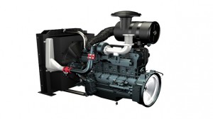
This manual has been prepared to help you use and maintain the DE series diesel engines (DE12, DE12T, DE12TI and DE12TIS) safely and correctly.
These economical and high-performance diesel engines(6 cylinders, 4 strokes, in-line, direct injection type) have been designed and manufactured to be used for overland transport or industrial purpose. They meet all the requirements such as low noise, fuel economy, high engine speed and durability.
Nonetheless, to obtain the best performance and long life of an engine, it is essential to operate it appropriately and to carry out periodic checks as instructed in this manual. You are requested to thoroughly read this manual from cover to cover and to acquaint yourself with all the information contained in this manual.
All information, illustration and specifications continued in this literature are based on the latest product information available at the time of publication approval. The right is reserved to make changes at any time without notice.
Please contact Daewoo dealer for the answers to any questions you may have about DE series engine’s features, operation or manuals.
CONTENTS
|
1. |
General information ………………………………………………………………………………………………… 1 |
||
|
1.1. Engine characteristics |
1.4. Engine performance curve |
||
|
1.2. Main data and specifications |
1.5. Exterior view of engine |
||
|
1.3. Engine specification(’98 type) |
|||
|
2. |
Major maintenance ……………………………………………………………………………………………….. |
22 |
|
|
2.1. Preventive maintenance |
2.2. Diagnostics and troubleshooting |
||
|
for the engine |
|||
|
3. |
Disassembly and reassembly of major components ………………………………………………. |
37 |
|
|
3.1. Disassembly |
3.3. Reassembly |
||
|
3.2. Inspection |
3.4. Breaking-in |
||
|
4. |
Maintenance of major components ………………………………………………………………………… |
79 |
|
|
4.1. Cooling system |
4.3. Fuel system |
||
|
4.2. Lubricating system |
4.4. Turbocharger |
||
|
5. |
Scan pole diagnosis for DE12TIS …………………………………………………………………………. |
142 |
|
|
5.1. Wire harness connection |
5.4. Sensor data |
||
|
5.2. System & Vehicle selection |
5.5. Actuator test |
||
|
5.3. Self-diagnosis(current) |
5.6. Flight record |
||
|
6. |
Maintenance specifications ………………………………………………………………………………….. |
154 |
|
|
6.1. Tightening torque |
6.2. Maintenance specification table |
||
|
• WORLDWIDE NETWORK |

1. General information
1.1. Engine characteristics
1.1.1.OMEGA combustion bowl
The OMEGA combustion bowl is a unit designed to perform high-efficiency, lowemission combustion. As the rim around the combustion bowl port of the upper of the piston has been machined in a smaller size than the interior of the combustion bowl, strong swirl is produced in the combustion bowl and strong squish flow makes the fuel be mixed more sufficiently with air.
Due to the application of OMEGA combustion system and optimal ultilization of intake and exhaust port configuration within the cylinder head, the DE12 series engines discharge a very low level of hazardous exhaust gases such as smoke, nitrogen oxide, hydrocarbon, or carbon monoxide and thus ensure high performance and low fuel consumption.
EA2M1001
<Figure. 1-1> OMEGA combustion bowl
— 1 —

1.1.2.Wastegated turbocharging system
1)What is the wastegated turbocharging system?
Turbocharger is a system designed to pressurize the intake air to increase engine output and decrease fuel consumption by using the energy of exhaust gas discharged from the engine. However, the turbocharger has a weak point at low engine speed, its performance may drop, thus performance at low speed is relatively low.
The WASTEGATED TURBOCHARGING SYSTEM is an up-to-date turbocharging system remedying such a defect, and the working principle is as follows:
A small-sized high performance turbine is used to improve engine performance at low speeds. As high charging efficiency can be obtained even If a small amount of exhaust gas is present at low speed. On the other hand, if higher charging pressure is produced than what is present at high speed, fuel consumption increases. To correct this, part of exhaust gas is forced to be discharged into the exhaust manifold through the waste gate, not through the turbine.
The waste gate is controlled by the ACTUATOR mounted in the turbocharger, and if the pressure in the turbocharger becomes higher than what is required for the engine, the waste gate is forced to open.
2)DE12T, DE12TI and DE12TIS engines are featured by the application of turbochager so that the torque in low speeds can be increased by 30% or more, not only to create high performance, just from the time of starting off the vehicle but also to greatly reduce fuel consumption.
Compressed air outlet por
Turbine
Intake air
Exhaust gas outlet port
Waste gate
Compressor
Actuator
<Figure 1-3> Turbochager
— 2 —
1.2. Main data and specifications
|
Engine Model |
DE12 |
DE12T |
DE12TI |
DE12TIS |
||||||
|
Type |
In-line, 4-stroke, vertical type |
|||||||||
|
Combustion chamber type |
OMEGA Combustion bowl |
|||||||||
|
Fuel injection |
Direct injection type |
|||||||||
|
Bore B stroke-No. of cylinders |
123mm B 155 — 6 |
|||||||||
|
Total displacement |
11,051cc |
|||||||||
|
Compression ratio |
17.1:1 |
17.1:1 |
16.5:1 |
16.8 |
||||||
|
Maximum power(PS) |
225 ps/2,200 rpm |
300 ps/2,200 rpm |
340 ps/2,100 rpm |
|||||||
|
Maximum torque |
81.5 kg.m/1,400 rpm |
110 kg.m/1,300 rpm |
135 kg.m/1,260 rpm |
|||||||
|
Injection timing |
12° BTDC |
9° BTDC |
12° BTDC |
1.0° BTDC |
||||||
|
Firing order |
1-5-3-6-2-4 |
|||||||||
|
Injection pump type |
S3000 |
S3000 |
S3S |
HD-TICS |
||||||
|
Governor type |
RFD-C/RLD |
RFD-C |
RFD-D |
RLD-J |
||||||
|
Timer type |
SP |
SP |
SPG |
Electronically control |
||||||
|
Nozzle type |
Multi-hole type(5-N0.29) |
Multi-hole type(5-N0.31) |
Multi-hole type(5-N0.33) |
Multi-hole type(5-N0.29) |
||||||
|
Feed pump type |
K-P |
K-P |
K-PS |
|||||||
|
Valve Timing |
||||||||||
|
Intake valve open at |
BTDC 18° |
BTDC 18° |
||||||||
|
Intake valve close at |
ABDC 34° |
ABDC 32° |
||||||||
|
Exhaust valve open at |
BBDC 46° |
BBDC 70° |
||||||||
|
Exhaust valve close at |
ATDC 14° |
ATDC 30° |
||||||||
|
Oil pump type |
Gear type |
|||||||||
|
Oil cooler type |
Water-cooler |
|||||||||
|
Fuel filter type |
Full flow type |
|||||||||
|
Oil capacity |
20M(Oil pan 17M) |
|||||||||
|
Coolant capacity |
19M |
|||||||||
|
Thermostat type |
Wax-pallet |
|||||||||
|
Starter : Voltage-output |
24V-6.0Kw |
|||||||||
|
Alternator : Voltage-capacity |
24V-45A |
|||||||||
— 3 —
1.3. Engine specification(’98 type)
Item
|
Average efficient comp.(kg/cm2) |
|||
|
n |
Max. horse power(ps/rpm) |
||
|
Max. torque(kg•m/rpm) |
|||
|
g |
Firing order |
||
|
i |
Engine dimension(LxWxH) |
||
|
Dry weight(kg) |
|||
|
n |
Cycle |
||
|
Piston Material |
|||
|
e |
Comp. ring |
||
|
No. of piston ring |
|||
|
Oil ring |
|||
|
Intake |
Open |
||
|
In. & Ex. |
Close |
||
|
Valve |
|||
|
timing |
Exhaust |
Open |
|
|
Close |
|||
|
Valve clearance |
Intake |
||
|
(cold engine) |
Exhaust |
||
|
Engine speed at no load |
|||
|
Lubricatring system |
Lubricating Type |
||
|
Oil capacity(M) |
|||
|
Oil pump type |
|||
|
Oil filter type |
|||
|
Oil cooler type |
|||
|
Manufacturer |
|||
|
Mounting location |
|||
|
Starting type |
|||
|
Engine type |
|||
|
Cylinder(No. arrangement) |
|||
|
Combustion chamber type |
|||
|
Valve position |
|||
|
Diameter x stroke |
|||
|
Compression ratio |
|||
|
Comp. pressure(kg/cm2-rpm) |
|||
|
E |
|||
|
DE12-228 |
DE12TI-280 |
DE12TI-310 |
DE12TIS |
||||||
|
DHI |
|||||||||
|
Under Seat |
|||||||||
|
SELF |
|||||||||
|
Diesel 4 Cycle |
Turbocharged & Intercooled |
||||||||
|
In-line, vertical |
|||||||||
|
Direct injection |
|||||||||
|
OHV |
|||||||||
|
123×155 |
|||||||||
|
17.1 |
16.1 |
16.8 |
|||||||
|
28-200 |
|||||||||
|
9.27 |
13.08 |
14.21 |
|||||||
|
228/2,200 |
280/2,100 |
310/2,100 |
340/2,100 |
||||||
|
80/1,400 |
115/1,260 |
125/1,260 |
140/1,260 |
||||||
|
1-5-3-6-2-4 |
|||||||||
|
1,317x747x1,015 |
1,317x847x1,064 |
||||||||
|
872 |
909 |
910 |
|||||||
|
4 |
|||||||||
|
AL |
|||||||||
|
2 |
|||||||||
|
1 |
|||||||||
|
BTDC 18° |
BTDC 18° |
||||||||
|
ABDC 34° |
ABDC 32° |
||||||||
|
BBDC 46° |
BBDC 70° |
||||||||
|
ATDC 14° |
ATDC 30° |
||||||||
|
0.3 |
|||||||||
|
0.3 |
|||||||||
|
550~600 |
|||||||||
|
Forced pressure type |
|||||||||
Gear
Strainer
20
Water cooled
— 4 —
|
Item |
DE12-228 |
DE12TI-280 |
DE12TI-310 |
DE12TIS |
|||||||||
|
Turbocharger type |
— |
Exhaust gas driven |
|||||||||||
|
Intercooler type |
— |
Air cooled |
|||||||||||
|
Engine |
Cooling type |
Forced water circulation |
|||||||||||
|
Cooling |
Coolant capacity |
19(engine only) |
|||||||||||
|
system |
Water pump type |
Centrifugal |
|||||||||||
|
Thermostat type |
Wax pellet |
||||||||||||
|
Fuel pump type |
Plunger |
||||||||||||
|
Fuel filter type |
Full flow |
||||||||||||
|
Fuel injection type |
Mechanical |
Electronic control |
|||||||||||
|
Inj. |
Type |
Inline |
|||||||||||
|
Timing |
BTDC 8° |
BTDC 12° |
BTDC 1.0° |
||||||||||
|
pump |
|||||||||||||
|
Fuel |
system |
Plunger Dia. |
12 |
||||||||||
|
system |
Cam lift(mm) |
11 |
12 |
14 |
|||||||||
|
Nozzle mounting |
Flange |
||||||||||||
|
Inj. |
Nozzle type |
Multi hole |
|||||||||||
|
No |
5 |
||||||||||||
|
nozzle |
Orifice |
||||||||||||
|
Dia.(mm) |
0.29 |
0.33 |
0.29 |
||||||||||
|
Inj. pressure(kg/cm2) |
220 |
130/220 |
163/224 |
||||||||||
|
Voltage(V) |
24V |
||||||||||||
|
Preheat |
Type |
Electric |
|||||||||||
|
-ing |
|||||||||||||
|
system |
Voltage(V) — Amp(A) |
22-120 |
|||||||||||
|
Electric |
Alternator |
Output(V-A) |
— |
— |
— |
— |
|||||||
|
system |
Regulator |
— |
— |
— |
— |
||||||||
|
Starter |
Type |
Reduction |
|||||||||||
|
Output(kW) |
24V-6.0kW |
||||||||||||
|
Ignition |
Type |
Air compression |
|||||||||||
— 5 —

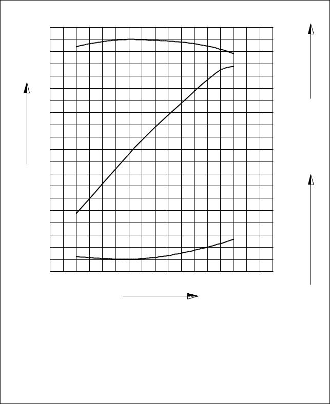
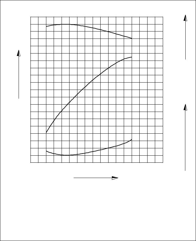
1.4. Engine performance curve
1.4.1. DE12
Output(ps)
220
200
180
160
140
120
100
|
85 |
|
|
80 |
m) |
|
. |
|
|
75 |
Torque(kg |
|
70 |
|
h) |
|
|
. |
|
|
170 |
consumption(g/ps |
|
165 |
|
|
160 |
Fuel |
|
1000 |
1200 |
1400 |
1600 |
1800 |
2000 |
2200 |
2400 |
Revolution(rpm)
|
Performance criteria |
ISO 1585(SAE J1349) |
|
Output(Max.) |
235 ps/2,200 rpm |
|
Torque(Max.) |
81.5 kg.m/1,400 rpm |
|
Fuel consumption ratio(min.) |
160 g/ps.h |
EQM1004I
— 6 —
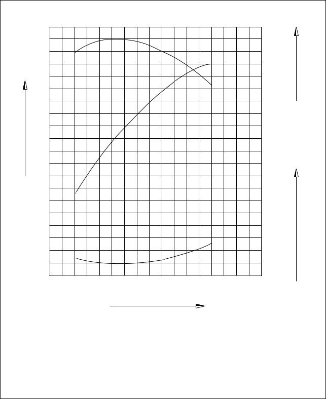
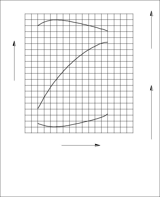
1.4.2. DE12(’98 type)
Output(ps)
220
200
180
160
140
120
100
|
1000 |
1200 |
1400 |
1600 |
1800 |
2000 |
2200 |
2400 |
Revolution(rpm)
|
h) |
|
|
. |
|
|
155 |
consumption(g/ps |
|
165 |
|
|
160 |
|
|
Fuel |
|
Performance |
ISO 1585(SAE J1349) |
|
Output(Max.) |
228 ps/2,200 rpm |
|
Torque(Max.) |
80 kg.m/1,400 rpm |
|
Fuel consumption ratio(min.) |
155 g/ps.h |
EQM1005I
— 7 —
![]()
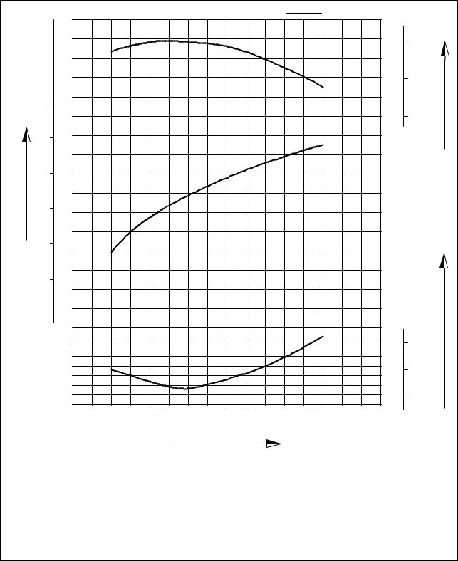
1.4.3. DE12T
Output(ps)
300
270
240
210
180
150
120
|
110 |
|
|
100 |
m) |
|
. |
|
|
90 |
Torque(kg |
|
80 |
|
h) |
|
|
. |
|
|
160 |
consumption(g/ps |
|
170 |
|
|
165 |
|
|
155 |
Fuel |
|
1 000 |
1200 |
1400 |
1600 |
1800 |
2000 |
2200 |
2400 |
Revolution(rpm)
|
Performance |
ISO 1585(SAE J1349) |
|
Output(Max.) |
300 ps/2,200 rpm |
|
Torque(Max.) |
110 kg.m/1,300 rpm |
|
Fuel consumption ratio(min.) |
155 g/ps.h |
EQM1006I
— 8 —
1.4.4. DE12TI
Output(ps)
340
310
280
250
220
190
160
|
135 |
|
|
130 |
m) |
|
. |
|
|
125 |
Torque(kg |
|
120 |
|
h) |
|
|
. |
|
|
155 |
consumption(g/ps |
|
160 |
|
|
150 |
Fuel |
|
1 000 |
1200 |
1400 |
1600 |
1800 |
2000 |
2200 |
2400 |
Revolution(rpm)
|
Performance |
ISO 1585(SAE J1349) |
|
Output(Max.) |
340 ps/2,100 rpm |
|
Torque(Max.) |
135 kg.m/1,260 rpm |
|
Fuel consumption ratio(min.) |
147 g/ps.h |
EQM1007I
— 9 —
1.4.5. DE12TI(280 ps : ’98 type)
Output(ps)
|
115 |
|
|
105 |
m) |
|
. |
|
|
95 |
Torque(kg |
|
h) |
|||||||||
|
. |
|||||||||
|
155 |
consumption(g/ps |
||||||||
|
150 |
|||||||||
|
145 |
Fuel |
||||||||
|
1000 |
1200 |
1400 |
1600 |
1800 |
2000 |
2200 |
2400 |
||
Revolution(rpm)
|
Performance |
ISO 1585(SAE J1349) |
|
Output(Max.) |
280 ps/2,100 rpm |
|
Torque(Max.) |
115 kg.m/1,260 rpm |
|
Fuel consumption ratio(min.) |
145 g/ps.h |
EQM1008I
— 10 —
1.4.6. DE12TI(310 ps : ’98 type)
Output(ps)
|
1000 |
1200 |
1400 |
1600 |
1800 |
2000 |
2200 |
2400 |
Revolution(rpm)
|
125 |
|
|
115 |
m) |
|
. |
|
|
105 |
Torque(kg |
|
h) |
|
|
. |
|
|
155 |
consumption(g/ps |
|
150 |
|
|
145 |
Fuel |
|
Performance |
ISO 1585(SAE J1349) |
|
Output(Max.) |
310 ps/2,100 rpm |
|
Torque(Max.) |
125 kg.m/1,260 rpm |
|
Fuel consumption ratio(min.) |
145 g/ps.h |
EQM1009I
— 11 —
1.4.7. DE12TIS
Power output(ps)
|
ps |
kW |
ISO 1585 |
kg.m |
|
|
N.m |
||||
|
1400 |
140 |
|||
|
1200 |
120 |
m) |
||
|
. |
||||
|
400 |
300 |
Torque(kg |
||
|
1000 |
100 |
|||
|
350 |
300
200
250
|
200 |
|||||||||
|
150 |
h) |
||||||||
|
100 |
|||||||||
|
. |
|||||||||
|
150 |
consumption(g/ps |
||||||||
|
g/kW.h g/ps.h |
|||||||||
|
220 |
160 |
||||||||
|
210 |
|||||||||
|
200 |
Fuel |
||||||||
|
190 |
140 |
||||||||
|
0 |
|||||||||
|
1200 |
1400 |
1600 |
1800 |
2000 |
2200 |
||||
|
1000 |
Revolution(rpm)
|
Performance |
ISO 1585(SAE J1349) |
|
Output(Max.) |
340 ps/2,100 rpm |
|
Torque(Max.) |
140 kg.m/1,260 rpm |
|
Fuel consumption ratio(min.) |
143 g/ps.h |
EA2M1002
— 12 —

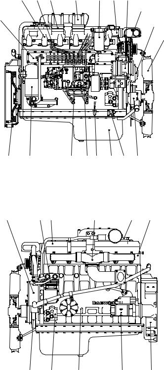
1.5. Exterior view of engine
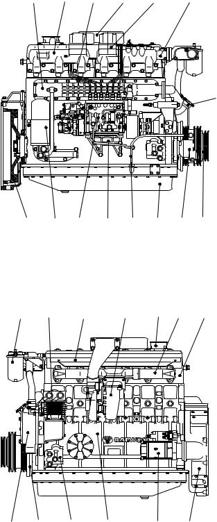
1.5.1. DE12for Bus
|
10 |
17 |
19 |
18 |
24 |
13 |
|
4 |
1. Cylinder block |
|||||||
|
2. Flywheel housing |
||||||||
|
3. Breather |
||||||||
|
4. Oil filler pipe |
||||||||
|
5. Vibration damper |
||||||||
|
6. Flywheel |
||||||||
|
7. V-pulley |
||||||||
|
8. Cylinder head |
||||||||
|
9. Oil filter |
||||||||
|
6 |
9 |
20 |
21 |
12 |
11 |
27 7 |
10. |
Oil cooler |
|
11. |
Oil pan |
|||||||
|
12. |
Oil dipstick |
|||||||
|
13. |
Cooling water pipe |
|||||||
|
14. |
Water pump |
|||||||
|
22 |
25 |
16 |
15 |
3 |
8 |
15. |
Exhaust manifold |
|
|
16. |
Heat shield |
|||||||
|
17. |
Intake manifold |
|||||||
|
18. |
Intake stake |
|||||||
|
19. |
Injection pipe |
|||||||
|
20. |
Injection pump |
|||||||
|
21. |
Injection pump bracket |
|||||||
|
22. |
Fuel filter |
|||||||
|
23. |
Starter |
|||||||
|
24. |
Air heater |
|||||||
|
25. |
Air compressor |
|||||||
|
26. |
Mounting bracket |
|||||||
|
27. |
Power steering pump |
|
14 |
5 |
26 |
1 |
23 |
2 |
EQM1010I
— 13 —
1.5.2. DE12for Truck
|
18 |
20 |
26 |
19 |
23 |
14 |
27 |
24
11
7
16
|
6 |
10 |
22 |
21 13 |
12 |
4 |
29 |
|
15 |
30 |
9 |
17 |
3 |
8 |
|
5 |
28 |
1 |
25 |
2 |
1.Cylinder block
2.Flywheel housing
3.Breather
4.Oil filler pipe
5.Vibration damper
6.Flywheel
7.Idle pulley
8.Cylinder head
9.Cylinder head cover
10.Oil filter
11.Oil cooler
12.Oil pan
13.Oil dipstick
14.Cooling water pipe
15.Water pump
16.Cooling fan
17.Exhaust manifold
18.Intake manifold
19.Intake stake
20.Injection pipe
21.Injection pump
22.Injection pump bracket
23.Fuel filter
24.Alternator
25.Starter
26.Air heater
27.Air-conditioning compressor
28.Engine mounting bracket
29.Power steering pump
30.Air compressor
EA2M1003
— 14 —
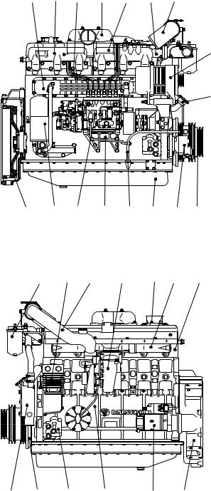
1.5.3. DE12Tfor Bus
|
10 |
16 |
20 |
18 |
25 |
13 |
4
|
6 |
9 |
21 |
22 |
12 |
11 |
28 |
7 |
|
23 |
26 |
17 |
19 |
3 |
15 |
8 |
|
14 |
5 |
27 |
1 |
24 |
2 |
EQM1011I
1.Cylinder block
2.Flywheel housing
3.Breather
4.Oil filler pipe
5.Vibration damper
6.Flywheel
7.V-pulley
8.Cylinder head
9.Oil filter
10.Oil cooler
11.Oil pan
12.Oil dipstick
13.Cooling water pipe
14.Water pump
15.Exhaust manifold
16.Intake manifold
17.Heat shield
18.Intake stake
19.Turbocharger
20.Injection pipe
21.Injection pump
22.Injection pump bracket
23.Fuel filter
24.Starter
25.Air heater
26.Air compressor
27.Mounting bracket
28.Power steering pump
— 15 —

1.5.4. DE12TI(340 ps)- for Bus
|
10 |
16 |
22 |
17 |
27 |
13 |
21 |
29
4
|
6 |
9 |
23 |
24 |
12 |
11 |
31 |
7 |
|
|
25 |
28 |
20 |
18 |
19 |
3 |
15 |
8 |
|
14 |
5 |
30 |
1 |
26 |
2 |
EQM1012I
1.Cylinder block
2.Flywheel housing
3.Breather
4.Oil filler pipe
5.Vibration damper
6.Flywheel
7.V-pulley
8.Cylinder head
9.Oil filter
10.Oil cooler
11.Oil pan
12.Oil dipstick
13.Cooling water pipe
14.Water pump
15.Exhaust manifold
16.Intake manifold
17.Intake stake
18.Turbocharger
19.Air pipe, T/C-A/P
20.Air pipe, A/P-I/C
21.Air pipe, A/P-I/C
22.Injection pipe
23.Injection pump
24.Injection pump bracket
25.Fuel filter
26.Starter
27.Air heater
28.Air compressor
29.Alternator
30.Mounting bracket
28. Power steering pump
— 16 —
1.5.5. DE12TI(280 ps : ’98 type)- for Bus
|
10 |
16 |
21 |
17 |
26 |
13 |
20 |
28
4
|
6 |
9 |
22 |
23 |
12 |
11 |
30 |
7 |
|
24 |
27 |
19 |
18 |
3 |
15 |
8 |
|
14 |
5 |
29 |
1 |
25 |
2 |
EQM1013I
1.Cylinder block
2.Flywheel housing
3.Breather
4.Oil filler pipe
5.Vibration damper
6.Flywheel
7.V-pulley
8.Cylinder head
9.Oil filter
10.Oil cooler
11.Oil pan
12.Oil dipstick
13.Cooling water pipe
14.Water pump
15.Exhaust manifold
16.Intake manifold
17.Intake stake
18.Turbocharger
19.Air pipe, T/C-A/P
20.Air pipe, A/P-I/C
21.Injection pipe
22.Injection pump
23.Injection pump bracket
24.Fuel filter
25.Starter
26.Air heater
27.Air compressor
28.Alternator
29.Mounting bracket
30.Power steering pump
— 17 —
![]()
1.5.6. DE12TI(310 ps : ’98 type)- for Bus
|
10 |
16 |
22 |
17 |
27 |
13 |
21 |
29
4
|
6 |
9 |
23 |
24 |
12 |
11 |
31 |
7 |
|
|
25 |
28 |
20 |
18 |
19 |
3 |
15 |
8 |
|
14 |
5 |
30 |
1 |
26 |
2 |
EQM1014I
1.Cylinder block
2.Flywheel housing
3.Breather
4.Oil filler pipe
5.Vibration damper
6.Flywheel
7.V-pulley
8.Cylinder head
9.Oil filter
10.Oil cooler
11.Oil pan
12.Oil dipstick
13.Cooling water pipe
14.Water pump
15.Exhaust manifold
16.Intake manifold
17.Intake stake
18.Turbocharger
19.Air pipe, T/C-A/P
20.Air pipe, A/P-I/C
21.Air pipe, A/P-I/C
22.Injection pipe
23.Injection pump
24.Injection pump bracket
25.Fuel filter
26.Starter
27.Air heater
28.Air compressor
29.Alternator
30.Mounting bracket
31.Power steering pump
— 18 —
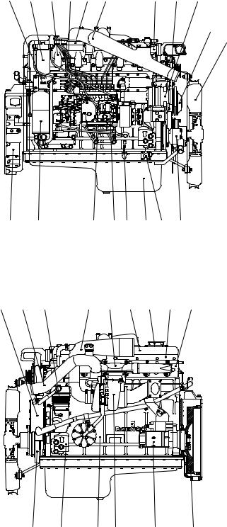
1.5.7. DE12TI — for Truck
|
11 |
27 |
19 |
24 |
30 |
20 |
14 |
28 |
31 |
7
16
|
2 |
10 |
26 |
25 13 |
12 |
4 |
33 |
|||
|
15 |
23 |
34 |
22 |
17 |
9 |
3 |
18 |
8 |
|
5 |
32 |
1 |
21 |
29 |
6 |
EA2M1004
1.Cylinder block
2.Flywheel housing
3.Breather
4.Oil filler pipe
5.Vibration damper
6.Flywheel
7.Idle pulley
8.Cylinder head
9.Cylinder head cover
10.Oil filter
11.Oil cooler
12.Oil pan
13.Oil dipstick
14.Cooling water pipe
15.Water pump
16.Cooling fan
17.Exhaust manifold
18.Heat screen
19.Intake manifold
20.Intake stake
21.Turbocharger
22.Air pipe, A/C-T/C
23.Air pipe, T/C-I/C
24.Injection pipe
25.Injection pump
26.Injection pump bracket
27.Fuel filter
28.Alternator
29.Starter
30.Air heater
31.Air-conditioning compressor
32.Engine mounting bracket
33.Power steering pump
34.Air compressor
— 19 —
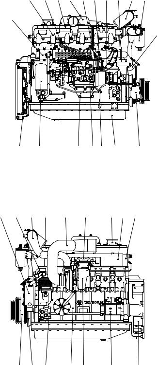
1.5.8. DE12TIS — for Bus
18 24 32 19 26 27 28 14 23 30
11
4
|
6 |
10 |
12 |
29 |
25 13 |
12 |
34 |
|
15 |
35 |
22 |
9 |
21 |
16 |
3 |
17 |
8 |
|
7 |
5 |
33 |
1 |
20 |
31 |
2 |
EA2M1005
1.Cylinder block
2.Flywheel housing
3.Breather
4.Oil filler pipe
5.Vibration damper
6.Flywheel
7.Crank shaft pulley
8.Cylinder head
9.Cylinder head cover
10.Oil filter
11.Oil cooler
12.Oil pan
13.Oil dipstick
14.Cooling water pipe
15.Water pump
16.Exhaust manifold
17.Heat screen
18.Intake manifold
19.Intake stake
20.Turbocharger
21.Air pipe, A/C-T/C
22.Air pipe, T/C-A/P
23.Air pipe, A/P-I/C
24.Injection pipe
25.Injection pump
26.Pick-up sensor
27.Prestroke actuator sensor
28.Rack sensor
29.Injection pump bracket
30.Fuel filter
31.Starter
32.Air heater
33.Engine mounting bracket
34.Power steering pump
35.Air compressor
— 20 —

1.5.9. DE12TIS — for Truck
30 19 24 33 20 26 27 28 14 34
31
11
7
16
|
2 |
10 |
29 |
25 13 |
12 |
4 |
36 |
|
15 |
23 |
37 |
9 |
22 |
17 |
18 |
3 |
8 |
|
5 |
35 |
1 |
21 |
32 |
6 |
EA2M1006
1.Cylinder block
2.Flywheel housing
3.Breather
4.Oil filler pipe
5.Vibration damper
6.Flywheel
7.Idle pulley
8.Cylinder head
9.Cylinder head cover
10.Oil filter
11.Oil cooler
12.Oil pan
13.Oil dipstick
14.Cooling water pipe
15.Water pump
16.Cooling fan
17.Exhaust manifold
18.Heat screen
19.Intake manifold
20.Intake stake
21.Turbocharger
22.Air pipe, A/C-T/C
23.Air pipe, T/C-I/C
24.Injection pipe
25.Injection pump
26.Pick-up sensor
27.Prestroke actuator sensor
28.Rack sensor
29.Injection pump bracket
30.Fuel filter
31.Alternator
32.Starter
33.Air heater
34.Air-conditioning compressor
35.Engine mounting bracket
36.Power steering pump
37.Air compressor
— 21 —

2. Major maintenance
2.1. Preventive maintenance
2.1.1.Cooling water
1)Check the coolant level of the radiator by removing the radiator filler cap, and add coolant if necessary.
2)Check the pressure valve opening pressure using a radiator cap tester. Replace the radiator filler cap assembly if the measured value does not reach the specified limit.
3)When injecting antifreeze solution, first drain out the old coolant from the cylinder block and radiator, and then clean them with cleaning solution.
4)Be sure to mix soft water with antifreeze solution .
5)A proportion of antifreeze is represented as the ratio of antifreeze in volume, and antifreeze must be added according to each ambient temperature as described below:
|
Antifreeze solution(%) |
Freezing point(C) |
|
20 |
-10 |
|
27 |
-15 |
|
33 |
-20 |
|
40 |
-25 |
|
44 |
-30 |
|
50 |
-40 |
 CAUTION
If you add antifreeze in excess of 50% in volume, the engine may be overheated. Avoid this.
As the individual freezing points corresponding to the above proportions of antifreeze are subject to change slightly according to the kind of antifreeze, you must follow the specifications provided by the antifreeze manufacturer.
6)When the ratio of antifreeze in the mixture decreases new coolant should be added to make up for the loss in old coolant resulting from engine operation, check the mix ratio with every replenishment of coolant, and top up as necessary.
7)To prevent corrosion or air bubbles in the coolant path, be sure to add a specific additive, i.e. corrosion inhibitor, to the coolant.
•Type : DAC65L
•Mix ratio : 1.5M of inhibitor to 50M of coolant
(Namely, add corrosion inhibitor amounting to 3% of water capacity.)
 Add antifreeze of at least 5% in volume to prevent possible engine corrosion in hot weather.
— 22 —
2.1.2.Fan belt
1)Use a fan belt of specified dimensions, and replace if damaged, frayed, or deteriorated.
2)Check the fan belt for belt tension. If belt tension is lower than the specified limit, adjust the tension by relocating the alternator and air conditioner. (Specified deflection: 10~15mm when pressed down with thumb)
2.1.3.Engine oil
1)Check oil level using the oil dipstick and replenish if necessary.
2)Check the oil level with the vehicle stationary on a level ground, engine cooled. The oil level must be between MAX and MIN lines on the stick.
3)Engine oil should be changed at the specified intervals. Oil in the oil filter also should be changed simultaneously.
(First oil change : 1,000km running)
• Suggested engines oils
|
Engine Model |
SAE NO. |
API NO |
|
DE12, DE12T,DE12TI |
15W40 |
CD grade or above |
|
DE12TIS |
15W40 |
CG grade |
2.1.4.Oil filter
1)Check for oil pressure and oil leaks, and repair or replace the oil filter if necessary.
2)Change the oil filter element simultaneously at every replacement of engine oil.
2.1.5.Fuel filter
1)Drain water in cartridge with losen the cock under filter from time to time.
2)The fuel filter should be replaced at every 20,000km
2.1.6.Air cleaner
1)Replace any deformed or broken element or cracked air cleaner.
2)Clean or replace the element at regular intervals
— 23 —
2.1.7.Valve clearance
1)Turn the crank shaft so that the piston in No. 1 cylinder reaches the TDC on compression
stroke, then adjust the valve clearance.
2)After releasing the lock nut for the rocker arm adjusting screw, insert a feeler gauge of specified thickness into the clearance between the rocker arm and valve stem, and adjust the clearance with the adjusting screw. Fully tighten the lock nut when a correct adjustment is obtained.
3)Carry out the same adjusting operation according to the firing order(1-5-3-6-2-4) (Valve clearance(with engine cooled): 0.30mm for both intake and exhaust)
2.1.8.Cylinder compression pressure
1)Stop the engine after warming up, then remove the nozzle holder assembly.
2)Install a special tool(gauge adapter) in nozzle holder hole and mount the compression gauge in position of the nozzle holder.
|
Standard |
28 kg/cm2 over |
|
Limit |
24 kg/cm2 or less |
|
Difference between each cylinder |
L10% or less |
3)Cut off fuel circulation, rotate the starter, then measure compression pressure in each cylinder.
6Testing conditions: Coolant temperature 20C, Engine speed, 200 rpm (10 turns)
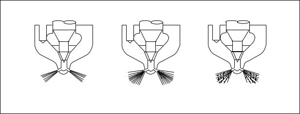
2.1.9.Injection nozzle
1)Assemble a nozzle to a nozzle tester.
2)Check injection pressure, and adjust the nozzle using the adjusting shim if the pressure does not meet the specified limit.
3)Check nozzle spray patterns and replace if damaged.
EFM1006I
<Figure 2-1> Nozzle spray patterns
— 24 —
2.1.10.Fuel injection pump
1)Check the fuel injection pump housing for cracks or breaks, and replace if damaged.
2)Check and see if the lead seal for idling control and speed control levers have not been removed.
2.1.11.Battery
1)Check the battery for damage or leaking of battery fluid(electrolyte) from cracks on the battery. Replace the battery if damaged.
2)Check battery fluid level and add distilled water if necessary.
3)Measure the specific gravity of the electrolyte in the battery. Recharge the battery if the hydrometer readings are lower than the specified limit(1.12~1.28)
— 25 —

2.2. Diagnostics and trouble shooting for the engine
2.2.1. Diagnostics
1. Engine won’t start
|
Starter does not turn |
Starter |
turns but engine does not start |
|||||||||||||||||||||||||||||||||||||
|
Check battery fluid and specific gravity |
Engine |
Fuel |
|||||||||||||||||||||||||||||||||||||
|
Normal |
Too low |
Check air cleaner |
Check fuel level |
||||||||||||||||||||||||||||||||||||
|
Replenish or recharge |
Normal |
Fouled |
Normal |
No fuel |
|||||||||||||||||||||||||||||||||||
|
Check cable connections |
Replace or clean element |
Replenish |
|||||||||||||||||||||||||||||||||||||
|
Normal |
Replenish or recharge |
Check compression pressure |
Check fuel injection |
||||||||||||||||||||||||||||||||||||
|
Check starter s/w |
Normal |
Too low |
Normal |
No fuel injection |
|||||||||||||||||||||||||||||||||||
|
Normal |
Replenish or recharge |
Retighten or replace |
Air bleeding and re-start |
||||||||||||||||||||||||||||||||||||
|
Check starter relay |
Check other parts |
Check injection timing |
|||||||||||||||||||||||||||||||||||||
|
Normal |
Replace |
Check valve clearance |
Normal |
Adjust |
|||||||||||||||||||||||||||||||||||
|
Check magnetic s/w |
Normal |
Adjust |
Check injection nozzle(injection |
||||||||||||||||||||||||||||||||||||
|
pressure, injection condition, etc.) |
|||||||||||||||||||||||||||||||||||||||
|
Normal |
Replenish or recharge |
Check cylinder head gasket |
|||||||||||||||||||||||||||||||||||||
|
Normal |
Repair or replace |
||||||||||||||||||||||||||||||||||||||
|
Disassemble and check starter motor |
Normal |
Replace |
|||||||||||||||||||||||||||||||||||||
|
Disassemble and check |
|||||||||||||||||||||||||||||||||||||||
|
Overhaul the engine |
injection pump |
||||||||||||||||||||||||||||||||||||||
|
(valve assembly, cylinder |
|||||||||||||||||||||||||||||||||||||||
|
liner, piston, etc.) |
|||||||||||||||||||||||||||||||||||||||
|
Check fuel feed pump for function |
|||||||||||||||||
|
Normal |
Check feed pump valve and strainer |
Air in the fuel |
|||||||||||||||
|
Disassemble and check injection pump |
Normal |
Clean or replace |
Retighten the joint and/or replace gasket |
||||||||||||||
|
Check fuel filter |
Air bleeding |
||||||||||||||||
|
Dirty element and/or overflow valve faulty |
Continuous entry of air in fuel system |
||||||||||||||||
|
Replace |
Disassemble and check feed pump |
||||||||||||||||
— 26 —

2. Engine overheating
|
Cooling system |
Fuel system |
Operating conditions |
||||||||||||||||||||||||||||||||||||
|
1. Overload |
||||||||||||||||||||||||||||||||||||||
|
2. Clogged radiator core |
||||||||||||||||||||||||||||||||||||||
|
3. Continued overrunning |
||||||||||||||||||||||||||||||||||||||
|
Check coolant level |
Check fuel quality |
|||||||||||||||||||||||||||||||||||||
|
Normal |
Too low |
Bad |
||||||||||||||||||||||||||||||||||||
|
Check fan belt for tension, wear, or breaks |
Clean or replace with the specified fuel |
|||||||||||||||||||||||||||||||||||||
|
Normal |
Repair or replace |
|||||||||||||||||||||||||||||||||||||
|
Check radiator cap |
Replenish |
Check water pump |
||||||||||||||||||||||||||||||||||||
|
Normal |
Replace |
External |
Internal |
|||||||||||||||||||||||||||||||||||
|
Check thermostat |
Retighten or repair |
Overhaul engine |
||||||||||||||||||||||||||||||||||||
|
Normal |
Replace |
|||||||||||||||||||||||||||||||||||||
|
Excessive fuel rate |
||||||||||||||||||||||||||||||||||||||
|
Check radiator |
||||||||||||||||||||||||||||||||||||||
|
Check injection nozzles |
||||||||||||||||||||||||||||||||||||||
|
Normal |
Damaged |
|||||||||||||||||||||||||||||||||||||
|
Normal |
Abnormal |
|||||||||||||||||||||||||||||||||||||
|
Repair or replace |
||||||||||||||||||||||||||||||||||||||
|
Repair or replace |
||||||||||||||||||||||||||||||||||||||
|
Clean coolant path |
||||||||||||||||||||||||||||||||||||||
|
Adjust or repair injection pump |
||||||||||||||||||||||||||||||||||||||
Check water pump
|
Normal |
Repair or replace |
|||
Overhaul the engine
— 27 —
![]()
3. Lack of power
|
Engine |
Chassis |
||||||||||||||||||||||
|
Fuel system |
Others |
Check for clutch slip |
|||||||||||||||||||||
|
Check fuel line for air |
Check air cleaner |
Adjust or replace clutch |
|||||||||||||||||||||
|
Check fuel feed pump |
Normal |
Clean or replace |
|||||||||||||||||||||
|
Normal |
Clean or replace |
Check engine control rod, link and |
|||||||||||||||||||||
|
cable |
|||||||||||||||||||||||
|
Check fuel filter element and overflow valve |
|||||||||||||||||||||||
|
Normal |
Adjust |
||||||||||||||||||||||
|
Normal |
Replace |
||||||||||||||||||||||
|
Check valve clearance |
|||||||||||||||||||||||
Check injection piping
|
Normal |
Repair or replace |
|||
Check injection nozzle(injection pressure, nozzle spray patterns, etc.)
|
Normal |
Adjust |
||
Check cylinder head gasket for break
|
Normal |
Replace |
|||
|
Normal |
Adjust or replace |
Overhaul engine(valve assembly) |
|||
Check injection timing
Normal 
 Adjust
Overhaul engine or injection pump
— 28 —

4. Low oil pressure
Check if oil pressure gauge indicates exactly
Check oil level
|
Normal |
Too low |
|||||||||||
|
Check cooling water temperature |
Refill with recommanded oil |
|||||||||||
|
Normal |
Too high |
|||||||||||
|
Check oil quality |
Refer to ‘Engine overheating’ |
|||||||||||
|
Normal |
||||||||||||
|
Check oil pressure relief valve |
Water, fuel, etc. mixed in oil |
Inadequate |
|||||||
|
Normal |
Adjust or replace |
Overhaul engine or injection pump |
Replace with suggested lub. oil |
||||||
|
Overhaul the engine |
|||||||||
— 29 —

5. High fuel consumption
Causes according to operating conditions
1.Overload
2.Frequent use of low gear position at high speed
3.Frequent use of high gear position at low speed
4.Clutch slip
5.Too low tire inflation pressure
Check fuel leakage
Normal
Check injection nozzle (injection pressure, spray patterns, etc.)
Normal
Check injection timing
Normal
Check compression pressure
|
Normal |
Check valve clearance |
|||||||||
|
Disassemble injection pump |
||||||||||
|
Repair or replace |
||||||||||
|
Cylinder liner |
||||||||||
|
Piston ring |
||||||||||
|
Normal |
Adjust |
|||||||||
|
Piston |
||||||||||
|
Check head gasket |
||||||||||
|
Normal |
Replace |
|||||||||
|
Overhaul engine |
||||||||||
|
(valve assembly, piston, |
||||||||||
|
cylinder liner, etc.) |
||||||||||
Oil leakage
Retighten or replace
— 30 —

6. Excessive oil consumption
Causes according to operating conditions
1.Too high lub. oil level
2.Continuous driving at low speed or with excessive cold engine
Check oil leakage
Check air cleaner
Clean or replace
|
Normal |
Oil leak |
|||||||||
|
Check oil quality |
External |
Internal |
||||||||
|
Replace with suggested lub. oil |
Retighten or replace |
Check compression pressure |
||||||||
Overhaul engine
(piston, cyl. liner)
Normal
Disassemble cylinder head(valve stem seal)
— 31 —

7. Engine knocks(excessive)
Check fuel and oil burning(Check carbon deposit from exhaust gas)
|
Not identified |
Identified |
|||||||||||||||||||||||
|
Check compression pressure |
Overhaul engine |
|||||||||||||||||||||||
|
Normal |
Too low |
|||||||||||||||||||||||
|
Check injection timing |
Check valve clearance, cyl. |
|||||||||||||||||||||||
|
head gasket for damage |
||||||||||||||||||||||||
|
Normal |
Adjust |
|||||||||||||||||||||||
|
Normal |
Replace or adjust |
|||||||||||||||||||||||
|
Check fuel quality |
||||||||||||||||||||||||
Overhaul engine
Use suggested fuel
— 32 —

8. Dead or weak battery
|
Battery |
Harness, switch |
Alternator |
|||||||||||||
|
Check battery fluid level |
Check wiring connections |
Check fan belt for |
|||||||||||||
|
for short, etc |
deflection, damage, etc. |
||||||||||||||
|
Repair or replace |
|||||||||||||||
|
Normal |
|||||||||||||||
|
Check battery fluid specs. |
Damaged battery case |
Battery discharged |
Battery overcharged |
||||||||||||
|
Replenish |
Replace |
Recharge |
Check alternator and |
||||||||||||
|
voltage regulator |
|||||||||||||||
Normal
Check charging condition
Discharged
Disassemble alternator and regulator
Abnormal
Adjust or replace
— 33 —

2.2.2. Trouble shooting
|
Complaint |
Cause |
Correction |
|
|
1) Difficulty in engine |
|||
|
starting |
|||
|
(1) Trouble in starter |
(See <2.2.1>) |
||
|
(2) Trouble in fuel system |
(See <Section 4.3 Fuel system>) |
Check valve and valve seat, |
|
|
(3) Lack of compression |
1 |
Valves holding open, skewed valve stem |
then repair or replace |
|
pressure |
2 |
Valve springs damaged |
Replace valve springs |
|
3 |
Leaky cylinder head gasket |
Replace gasket |
|
|
4 |
Worn pistons, piston ring, or liner |
Replace |
|
|
2) Rough engine idling |
|||
|
1 |
Wrong injection timing |
Adjust |
|
|
2 |
Air in injection pump |
Air bleeding |
|
|
3) Lack of engine power |
|||
|
(1) Engine continues to |
1 |
Valve clearance incorrect |
Adjust |
|
lack power |
2 |
Valve poorly seated |
Repair |
|
3 |
Leaky cylinder head gasket |
Replace gasket |
|
|
4 |
Piston rings worn, sticking, or |
Replace piston rings |
|
|
damaged |
|||
|
5 |
Injection timing incorrect |
Adjust |
|
|
6 |
Volume of fuel delivery insufficient |
Adjust injection pump |
|
|
7 |
Nozzle injection pressure incorrect |
Adjust or replace nozzles |
|
|
or nozzles seized |
|||
|
8 |
Feed pump faulty |
Repair or replace |
|
|
9 |
Restrictions in fuel pipes |
Repair |
|
|
10 |
Volume of intake air insufficient |
Clean or replace air cleaner |
|
|
(2) Engine lacks power on |
1 |
Compression pressure insufficient |
Overhaul engine |
|
acceleration |
2 |
Injection timing incorrect |
Adjust |
|
3 |
Volume of fuel delivery insufficient |
Adjust injection pump |
|
|
4 |
Injection pump timer faulty |
Repair or replace |
|
|
5 |
Nozzle injection pressure or spray |
Repair or replace |
|
|
angle incorrect |
|||
|
6 |
Feed pump faulty |
Repair or replace |
|
|
7 |
Volume of intake air insufficient |
Clean or replace air cleaner |
|
|
4) Engine overheating |
|||
|
1 |
Lack of engine oil or poor oil |
Replenish or replace |
|
|
2 |
Lack of coolant |
Replenish or replace |
|
|
3 |
Fan belts slipping, worn or damaged |
Adjust or replace |
|
|
4 |
Water pump faulty |
Repair or replace |
|
|
5 |
Thermostat inoperative |
Replace |
|
|
6 |
Valve clearance incorrect |
Adjust |
|
|
7 |
Back pressure in exhaust line |
Clean or replace |
|
— 34 —

|
Complaint |
Cause |
Correction |
|
|
5) Engine noises |
|||
|
It is important to correctly locate the |
|||
|
causes of noise since generally nois- |
|||
|
es may originate from various engine |
|||
|
components such as rotating parts, |
|||
|
sliding parts, etc. |
|||
|
(1) Crankshaft |
1 |
Oil clearance excessive due to |
Replace bearings and grind |
|
worn bearings or crankshaft |
crankshaft |
||
|
2 |
Crankshaft worn out-of-round |
Grind or replace crankshaft |
|
|
3 |
Restrictions in oil ports and resul- |
Clean oil path |
|
|
tant lack of oil supply |
Replace bearings and grind |
||
|
4 |
Bearings seized up |
crankshaft |
|
|
(2) Conn. rod and conn. |
|||
|
1 |
Conn. rod bearings worn out-of- |
Replace bearings |
|
|
rod bearings |
round |
||
|
2 |
Crank pin worn out-of-round |
Grind crankshaft |
|
|
3 |
Conn. rod skewed |
Repair or replace |
|
|
4 |
Bearings seized up |
Replace bearings and grind |
|
|
crankshaft |
|||
|
5 |
Restrictions in oil ports and resul- |
Clean oil path |
|
|
tant lack of oil supply |
|||
|
(3) Pistons, piston pins, |
|||
|
1 |
Piston clearance excessive due to |
Replace pistons and piston |
|
|
and piston rings |
worn piston and piston rings |
rings |
|
|
2 |
Piston or piston pin worn |
Replace pistons and piston |
|
|
rings |
|||
|
3 |
Piston seized up |
Replace pistons |
|
|
4 |
Piston poorly seated |
Replace pistons |
|
|
5 |
Piston rings damaged |
Replace piston rings |
|
|
(4) Others |
|||
|
1 |
Crankshaft and/or thrust bearing |
Replace thrust bearings |
|
|
worn |
|||
|
2 |
Camshaft end play excessive |
Replace thrust plate |
|
|
3 |
Idle gear end play excessive |
Replace thrust washers |
|
|
4 |
Timing gear backlash excessive |
Adjust or replace |
|
|
5 |
Valve clearance excessive |
Adjust valve clearance |
|
|
6 |
Tappets and cams worn |
Replace tappets and camshaft |
|
|
6) Excessive fuel |
1 |
Injection timing incorrect |
Adjust |
|
consumption |
2 |
Volume of fuel injection excessive |
Adjust injection pump |
|
3 |
Tire under-inflated |
Adjust |
|
|
4 |
Gear selection inadequate(frequent |
Select gears correctly accord- |
|
|
use of low gears) |
ing to load |
||
— 35 —

|
Complaint |
Cause |
Correction |
|
|
7) High oil consumption |
|||
|
(1) Oil leaking into |
1 |
Clearance between cylinder liner |
Replace |
|
combustion chamber |
and piston excessive |
||
|
2 |
Piston rings and ring grooves |
Replace pistons and piston |
|
|
worn excessively |
rings |
||
|
3 |
Piston rings broken, worn, or sticking |
Replace piston rings |
|
|
4 |
Piston rings gaps set incorrectly |
Correct |
|
|
5 |
Piston skirt portion broken, worn |
Replace pistons |
|
|
excessively |
|||
|
6 |
Oil return holes in oil control ring |
Replace piston rings |
|
|
restricted |
|||
|
7 |
Oil ring seated incorrectly |
Replace piston rings |
|
|
8 |
Breather piping restricted |
Clean or replace |
|
|
(2) Oil leaking past cylinder |
|||
|
1 |
Valve stems and valve guide |
Replace as complete set |
|
|
head |
loose excessively |
||
|
2 |
Valve stem seals worn |
Replace seals |
|
|
3 |
Leaky cylinder head gasket |
Replace gasket |
|
|
(3) Oil leaks |
|||
|
1 |
Applicable parts loosened |
Replace or repair gasket |
|
|
2 |
Applicable packings worn |
Replace packings |
|
|
3 |
Oil seals worn |
Replace oil seals |
|
— 36 —

3. Disassembly and reassembly of major components
3.1. Disassembly
3.1.1.General precautions
1)Maintenance operation should be carried out in a bright and clean place.
2)Before disassembly, provide parts racks for storage of various tools and disassembled parts.
3)Arrange the disassembled parts in the disassembly sequence and take care to prevent any damage to them.
3.1.2.Engine oil
1)Take out the oil dipstick.
2)Remove the drain plug from the oil pan and drain out the engine oil into a container.
3)Reassemble the drain plug with the oil pan after draining out the engine oil.
3.1.3. Cooling water
1)Remove the drain plug from the cylinder block and drain out the cooling water into a container.
3.1.4.Fan belt
1)Remove the fan guide and bracket.
2)Loosen the tension adjusting nuts installed on the alternator and air-condi- tioning compressor, and take off the fan belt.
EQM3003I
— 37 —
![]()
3.1.5. Cooling fan
1)Remove the flange fixing bolts, then take off the flange and cooling fan.
3.1.6.Oil level gauge guide tube
1)Loosen the flange nut installed on the ladder frame to remove the guide tube.
3.1.7.Alternator
1)Loosen the alternator fixing bolts to disassemble the alternator, then remove the tension adjusting bolt and bracket.
|
EQM3006I |
|
|
3.1.8. Air-conditioning compressor |
|
|
1) |
Remove the compressor fixing bolts and |
|
disassemble the A/C compressor. |
|
|
2) |
Disassemble the A/C compressor ten- |
|
sion adjusting bolt and alternator fixing |
|
|
bracket. |
|
|
3) |
Disassemble the A/C compressor fixing |
|
bracket. |
|
|
EQM3007I |
|
|
— 38 — |

3.1.9.Fuel filter
1)Remove fuel hoses connected to the fuel injection pump, take off the bracket fixing bolts, then disassemble the fuel filter.
3.1.10.Breather
1)Loosen the clamp screw to remove the rubber hose.
3.1.11.Injection pipe
1)Unscrew the hollow screws to disassemble the fuel return pipe.
2)Remove the nuts installed on the fuel injection pump and nozzles, then disassemble the injection pipe.
3.1.12. Air heater
1)Remove the electrical wiring for the air heater.
2)Disassemble the intake pipes by loosening the nuts installed thereon.
3)Disassemble the air heater and gasket.
3.1.13. Intake manifold
1)Remove the air hose connected to the fuel injection pump.
2)Loosen the intake manifold fixing bolts, then disassemble the intake manifold.

3.1.14.Turbocharger (for DE12T / DE12TI / DE12TIS only)
1)Release the clamp screw of the rubber hose connected to the intake manifold, and take off the intake pipes both simultaneously.
2)Unscrew the exhaust pipe bracket fixing bolts, release the nuts installed on the turbocharger, then disassemble the exhaust pipe.
3)Remove the turbocharger after removing the oil supply pipe and return pipe and releasing the fixing nuts.
3.1.15. Exhaust manifold
1) Release the exhaust manifold fixing bolts, disassemble the exhaust manifold, then remove the heat shield and gasket.
Note : Make sure to release the nuts one after another because the exhaust manifold will be removed if you unscrew the two nuts simultaneously.
3.1.16. Starter
1)Unscrew the starter fixing bolts, then disassemble the starter.
3.1.17. Thermostat
1)Remove the by-pass pipe connected to the water pump, unscrew the thermostat fixing bolts, then dissemble the thermostat assembly.
2)Disassemble the thermostat housing and remove the thermostat.
3)Disassemble the water pipe by unscrewing the bolts and nuts installed on the cylinder head.

3.1.18. Fuel injection pump
1)Remove the oil supply pipe and return pipe connected to the fuel injection pump.
2)Unscrew the bolts connecting the coupling and drive shaft, loosen the injec-
tion pump attaching bolts, then disassemble the injection pump.
Note : Place the No.1 cylinder in the
exact ‘OT’ position to disassem-
ble the injection pump.
3)Release the pump fixing bracket bolts to disassemble the bracket from the
cylinder block.
Note : Do not interchange the shims as
they must be installed in their
original positions at reassembly.
3.1.19. Oil filter
1)Using a filter remover, remove the filter element.
2)Remove the pipe connected to the oil cooler.
3)Loosen the oil filter fixing bolts and disassemble the oil filter head from the cylinder block.
EQM3018S
3.1.20. Idle pulley
1)Remove the bolts and disassemble the idle pulley.
EQM3019S
— 41 —

3.1.21. Power steering pump
1)Remove the oil hoses.
2)Unscrew the hex bolts and remove the steering pump.
EQM3020S
3.1.22. Water pump
1)Remove the water pipe connected to the expansion tank
2)Remove the water pipe and hoses connected to the water pump.
3)Unscrew the water pump fixing bolts and remove the water pump.
EQM3021S
3.1.23. Air compressor
1)Remove the oil hose, water pipe, air pipe connected to the air compressor, remove the air cooler fixing bolts, then disassemble the air compressor from the timing gear case.
EQM3022S
3.1.24. Vibration damper
1)Unscrew the pulley fixing bolts and disassemble the pulley-vibration damper assembly.
2)Unscrew the vibration damper fixing bolts and disassemble the damper from the pulley.
EQM3023S
— 42 —

3.1.25. Timing gear case cover
1)Disassemble the oil seal using an oil seal removing jig.
2)Remove the cover fixing bolts and disassemble the cover from the timing gear case.
3.1.26. Idle gear
1)Unscrew the idle gear fixing bolts and disassemble the thrust washer and idle gear.
2)Disassemble the idle gear pin using a rubber hammer to prevent damage to them.
3.1.27. Fuel injection pump drive assembly
1)Remove the dowel pin for the steering pump.
2)Unscrew the injection pump drive shaft bearing housing fixing bolts and remove the injection pump drive assembly in which the shaft, gear, bearings, and housing are put together.
3.1.28. Cylinder head cover
1)Unscrew the cover fixing bolts and disassemble the cover.
2)Keep the bolts in an assembly state so that the packings and washers may not be lost, and keep the cover packing as assembled with the cover.

3.1.29. Rocker arm assembly
1)Unscrew the rocker arm bracket bolts and remove the rocker arm assembly.
2)Take off the snap rings to remove the washers and rocker arm, then unscrew the bracket fixing bolts to take off the bracket and springs.
3)Take out the push rods.
3.1.30. Injection nozzle
1)Remove the nozzle fixing nuts and extract the nozzles.
2)Remove the nozzle tube using nozzle tube removing jig.
Do not perform disassembly opera-
tion unless coolant, gas, etc. leak
out.
3.1.31. Cylinder head
1)Unscrew the cylinder head fixing bolts and take off the cylinder head.
2)Remove the cylinder head gasket.
3.1.32. Valve and valve stem seal
1)Compress the valve spring retainer using a jig and take off the valve cotter pin.
2)Disassemble the valve springs and retainer.
3)Take off the valve.
4)Remove and discard the valve stem seal using a general tool as it should not be re-used.
EQM3029I
Compress the spring
EJM3027S
— 44 —

3.1.33. Oil cooler
1)Remove the water pipe connected to the water pump.
2)Unscrew the oil cooler cover fixing bolts and disassemble the oil cooler assembly from the cylinder block.
3)Unscrew the oil cooler fixing bolts and remove the oil cooler from the oil cooler cover.
3.1.34. Oil pan
1)Stand the engine with the flywheel housing facing toward the bottom.
2)Release the oil pan fixing bolts, remove the stiffeners, then disassemble the oil pan.
3.1.35. Oil pump and oil pipe
1)Unscrew the oil inlet pipe bracket bolts, releasing the pipe fixing bolts, then disassemble the oil suction pipe assembly.
2)Disassemble the oil pipe feeding oil from the oil pump to the cylinder block.
3)Unscrew the oil pump fixing bolts and disassemble the oil pump.
3.1.36. Ladder frame
1) Disassemble the ladder frame.

3.1.37. Piston and connection rod
1) Disassemble the pistons by two hands while turning the crankshaft.
2)Unscrew the conn. rod fixing bolts and take off the pistons and conn. rods in the direction of piston.
EQM3035I
3)Remove the piston pin snap rings, take off the piston pin, then disconnect the conn. rod from the piston.
|
EQM3036S |
||
|
4) |
Disassemble the piston rings using ring |
|
|
pliers. |
||
|
5) |
Take care not to interchange the disas- |
|
|
sembled parts and keep them in the |
Piston ring jig |
|
|
sequence of cylinder No. |
EQM3037S
3.1.38. Cylinder liner
1) Take off the cylinder liner.
EQM3038I
— 46 —

3.1.39. Flywheel
1)Position the engine so that the head installing surface of the cylinder block faces down.
2)Unscrew the flywheel fixing bolts and fit a dowel pin.
3)Install flywheel disassembling bolts in the bolt holes machined on the flywheel, and disassemble the flywheel.
3.1.40. Oil seal
1)Take off the rear oil seal using an oil seal disassembling jig.
2)If only the inside guide ring is removed, use a general tool to take off the outside seal.
3.1.41. Flywheel housing
1)Loosen the housing fixing bolts and disassemble the flywheel housing.
|
EQM3041I |
|
|
3.1.42. Cam shaft and tappet |
|
|
1) |
Remove the cam shaft gear. |
|
2) |
Take off the cam shaft gear thrust |
|
washer. |
|
|
3) |
Take out the cam shaft carefully not to |
|
damage the cam shaft. |
|
|
4) |
Slide out the tappets by hand. |
|
EQM3042I |
|
|
— 47 — |
 Loading…
- Manuals
- Brands
- Doosan Manuals
- Engine
- DE12T
- Operation & maintenance manual
-
Contents
-
Table of Contents
-
Bookmarks
Quick Links
Related Manuals for Doosan DE12T
Summary of Contents for Doosan DE12T
-
Page 2
/P126TI /P126TI-1/DE12T. The POLUS means ‘Power Plus’ that is represented more powerful Doosan generating-set engines and it is marked on engine name as an initial P. On the other hand, intial D stands for standard engine prior to POLUS version. -
Page 3: Table Of Contents
CONTENTS <Operation> 1. Safety Regulations ……………………1 1.1. General Notes 1.4. Regulations Designed to Prevent Pollution 1.2. Regulations Designed to Prevent Accidents 1.5. Notes on Safety in Handling Used Engine Oil 1.3. Regulations Designed to Prevent Damage to Engine and Premature Wear 2.
-
Page 4
9.4. Breaking-in 10. Maintenance of Major Components ……………… 113 10.1. Cooling System 10.3. Fuel Injection Pump 10.2. Lubricating System 10.4. Turbocharger 11. Special Tool List ……………………163 • Appendix • Part & After service center • Applications for Doosan Engine… -
Page 5: General Notes
1. Safety Regulations 1.1. General Notes Handling diesel engines and the necessary resources is no problem when the personnel com- missioned with operation and maintenance are trained accordingly and use their common sense. This summary is a compilation of the most important regulations. These are broken down into main sections which contain the information necessary for preventing injury to persons, damage to property and pollution.
-
Page 6
1.2.2. During maintenance and care ¥ Always carry out maintenance work when the engine is switched off. If the engine has to be maintained while it is running, e.g. changing the elements of change-over filters, remember that there is a risk of scalding. Do not get too close to rotating parts. ¥… -
Page 7
2) If faults occur, find the cause immediately and have it eliminate in order to prevent more serious of damage. 3) Use only genuine DAEWOO spare parts. DAEWOO will accept no responsibility for damage resulting from the installation of other parts which are supposedly Òjust as goodÓ. 4) In addition to the above, note the following points. -
Page 8
Health precautions ¥ Avoid prolonged or repeated skin contact with used engine oil. ¥ Protect your skin by means of suitable agents (creams etc.) or wear protective gloves. ¥ Clean skin which has been in contact with engine oil. — Wash thoroughly with soap and water, A nailbrush is an effective aid. — Certain products make it easier to clean your hands. -
Page 9: Engine Assembly
2. General Information 2.1. Engine Assembly 2.1.1. Engine sectional view (Longitudinal) 14 15 EA8M1002 1. Cooling fan 7. Piston pin 13. Crankshaft 2. Exhaust valve 8. Piston 14. Oil pan 3. Valve spring 9. Combustion chamber 15. Connecting rod 4. Oil filter 10.
-
Page 10
2.1.2. Engine sectional view (Cross) EA8M1003 1. Intake manifold 7. Injection nozzle assembly 2. Fuel filter 8. Rocker arm 3. Oil cooler 9. Cylinder head cover 4. Injection pump 10. Exhaust manifold 5. Cylinder block 11. Piston ring 6. Oil filter 12. -
Page 11
2.1.3. Engine assembly views 1) DE12T 3 12 4 13 18 11 10 20 21 26 EA8M1004 1. Cooling fan 10. Flywheel housing 19. Thermostat 2. Cooling water pipe 11. Flywheel 20. Injection pump 3. Oil filler cap 12. Exhaust manifold 21. -
Page 12
2) P126TI / P126TI- 9 10 14 15 16 17 18 20 21 EA8M1005 1. Cooling fan 8. Oil pan 18. Injection pipe 2. Cooling water pipe 9. Starter 19. Thermostat 3. Air pipe 10. Flywheel housing 20. Injection pump (Intercooler Intake manifold) 11. -
Page 13
2.2. Engine Specification Engine Model DE12T P126TI P126TI-1 P126TI- Items Water-cooled, 4 cycle in-line Water-cooled, 4 cycle in-line type Engine type type Turbo charged Turbo charged & intercooled Combustion chamber type Direct injection type Cylinder liner type Replaceable dry liner… -
Page 14: Engine Model And Serial Number
They are also referred to as engine model and serial number because of their location. EA8O3001 ¥ Engine serial No. (example 1 : DE12T) EBHOA300001 MODEL BORE Serial No. SPEED 1500/1800…
-
Page 15: Engine Type
3.2. Engine Type The Engines DE12T/ P126TI / P126TI- are in-line vertical water-cooled 6-cylinder four-stroke diesel engines with direct injection. DE12T is turbo-charged engine, and P126TI / P126TI- models are turbo-charged and inter-cooled engine. 3.2.1. Cylinder block The cylinder block is a single piece of alloy cast iron. To increase its stiffness, it is extended to a level below the crankshaft center line.
-
Page 16: Engine Timing
3.3. Engine Timing Camshaft, oil pump and injection pump are driven by a gear train arranged at the front end. Injection pump gear Camshaft gear Water pump gear (Z = 72) (Z = 72) (Z = 29) Idle gear (Z = 52) Crankshaft gear (Z = 36) Oil pump idle gear…
-
Page 17: Lubrication System
3.5. Lubrication System The engine is equipped with force-feed lubrication. The pressure is produced by a gear pump whose drive gear is in direct mesh with the crankshaft gear at the front end of cylinder block. The oil pump draws the oil from the oil sump and delivers it through the oil cooler and oil filter to the main distributor gallery and from there to the main bearings, big-end bearings and camshaft bearings as well as to the small-end bearings and the rocker arms.
-
Page 18: Air Cleaner
3.5.1. Oil cooler An oil cooler is provided between the oil filter and the cylinder block. This cooler is a flat tube type with turbulence inserts and operated by the coolant. 3.5.2. Oil filter Check for oil pressure and oil leaks, and repair or replace the oil filter if necessary.
-
Page 19
3.7.1. Fuel filter This fuel filter has two functions not only oil filtering but also water separating. Before entering the suction chamber of the injection pump, the fuel is cleaned in a strainer of fuel feed pump and a fuel filter. Drain water in cartridge with loosening the cock under filter manually (6) from time to time. -
Page 20
Fuel oil selection chart General Fuel ASTM No. 1 No. 2 DIN 51601 Classification Test ASTM 1-D ASTM 2-D Gravity, û D 287 40 ~ 44 33 ~ 37 0.815 ~ 0.855 Flash Point D 93 100 (38) 125 (52) 131 (55) û… -
Page 21
3.8. Cooling System The engine has a liquid-cooling system. The fresh water pump is a maintenance-free by gear from the crankshaft. Depending on the agreed extent of delivery and the design of the engine, the coolant circuit can be equipped with temperature monitors which, in the event of loss of coolant, shut the engine down. -
Page 22
For the improper control might give the fatal damage to the cooling water pump and cylinder liners, detail care is needed. ¥ Since DE12T , P126TI and P126TI- cylinder liner is dry type, particularly the cooling water control should be applied thoroughly. -
Page 23
Note : In taking the cooling water sample, if the water in auxiliary tank were taken, it is hard to measure the accurate density. Take the cooling water sample necessarily loosen- ing the cooling water discharge plug. 2) At the state of a test paper soaked in the sampled water, after taking the paper out through water agitation, shake off the water. -
Page 24
3.9. V-belt Tension Check and Adjust By the finger-pressure the belt is pressed by Press hear here 10mm ~ 15mm between the fan pulley and 15mm the alternator pulley in normal condition. For Alternator the adjustment of the tension, loosen the Pulley Pulley adjusting bolts which support the alternator,… -
Page 25: Electrical Equipment
3.11. Electrical Equipment 3.11.1. Alternator The alternator is fitted with integral silicon rectifiers. A transistorized regulator mounted on the alternator body interior limits the alternator voltage. The alternator should not be operated except with the regulator and battery connected in circuit to avoid damage to the rectifier and regulator.
-
Page 26
3.11.2. Starter motor The sliding-gear starter motor is flanged to the rear of the flywheel housing on the left-hand side. When the starting key switch is turned on, the starter motor pinion flies out and engages the ring gear of the flywheel. Then the main contact is closed, current flows, and the engine is started. -
Page 27: Preparation
4. Commissioning and Operation 4.1. Preparation At the time of initial commissioning of a new or overhauled engine make sure to have observed the ÒTechnical Information for the installation DAEWOO generator enginesÓ. ¥ Oil filler neck on cylinder head cover Before daily starting of the engine, check the fuel, coolant and oil level, replenish if necessary.
-
Page 28
At the end of the break-in period, remove break-in oil and replace the oil filter. Fill oil pan with recommended engine oil. Refer to following table. <Engine Oil capacity> Oil pan (only) DE12T 23 liter P126TI/P126TI- 23 liter 4.2.3. Operating after break-in When starting a cold engine, always allow the engine to warm up gradually. -
Page 29: Inspection After Starting
4.3. Inspections after Starting During operation the oil pressure in the engine lubrication system must be monitored. If the mon- itoring devices register a drop in the lube oil pressure, switch off the engine immediately. And the charge warning lamp of the alternator should go out when the engine is running. ¥…
-
Page 30
4.5. Tuning the Engine The purpose of an engine tune-up is to restore power and performance thatÕs been lost through wear, corrosion or deterioration of one or more parts or components. In the normal operation of an engine, these changes can take place gradually at a number of points, so that itÕs seldom advisable to attempt an improvement in performance by correction of one or two items only. -
Page 31: Periodical Inspection And Maintenance
5. Maintenance and Care 5.1. Periodical Inspection and Maintenance In order to insure maximum, trouble-free engine performance at all times, regular inspection, adjustment and maintenance are vital. ¥ Daily inspections in below figure should be checked every day. ¥ The maintenance should be executed thoroughly at regular intervals. (Refer to «…
-
Page 32
5.2.3. Oil exchange procedure While the oil is still hot, exchange oil as fol- lows: ¥ Take out the oil dip dipstick. ¥ Remove the drain valve from oil pan and the drain plug form oil filter head, then drain out the engine oil into a container. Drain Plug EA8O5001 ¥… -
Page 33
¥ Recommend of lubricating oil Initial factory filling is high quality break-in oil (API Service CH-4 grade). During the break- in period (50 hours), check the oil level frequently. Somewhat higher oil consumption is nor- mal until piston rings are seated. The oil level should be maintained in the safe range between Min. -
Page 34: Cooling System
5.2.4. Replacement of oil filter cartridge At the same times of oil exchanges, replace the oil filter cartridge. ¥ Drain engine oil by loosening the drain Cartridge plug on the filter head. Caution : DonÕt forget tightening the drain plug after having drained engine oil.
-
Page 35
c) Loosen the coolant drain plug. Loosen the coolant drain plug of the cylinder block. EAMD001I Caution : When removing the pressure filler cap while the engine is still hot, cover the cap with a rag, then turn it slowly to release the internal steam pressure This will pre- vent a person from scalding with hot steam spouted out from the filler port. -
Page 36
5.3.3. Intercooler The intercooler is air to air type and has a large cooling fan capacity. The intercooler life and performance depends on the intake air condition greatly. Fouled air pollutes and clogs the air fins of intercooler. As a result of this, the engine output is decreased and engine malfunction is occurred. -
Page 37: Air Intake System
5.4. Air Intake System 1. Connection port, fouling indicator 2. Cleaner housing 3. Clamp 4. Element 5. Hexagon nut 6. Cover 7. Dust bowl EA6O5012 5.4.1. Maintenance (only when engine is switched off) Empty the dust bowl (7) regularly. The bowl should never be filled more than halfway with dust. On slipping off the two clamps (3), the dust bowl can be removed.
-
Page 38
5.4.3. Cleaning filter elements ¥ By compressed air (Wear goggles) For the purpose, the air gun should be fit- ted with a nozzle extension which is bent û at the discharge end and which is long enough to reach down inside to the bottom of the element. -
Page 39: Fuel System
5.5. Fuel System 5.5.1. Fuel filter ¥ After every 200 hour of operation, drain the water and sediment from the fuel- water separator. ¥ Shut off the engine. Use your hand to open the drain valve ¥ Turn the valve counter clockwise approxi- mately 2 ~ 3 turns until draining occurs.
-
Page 40
5.5.3. Fuel system checks Fill the tank with the recommended fuel. Keeping tanks full reduces water condensation and helps keep fuel cool, which is important to engine performance. Make sure fuel supply valves (if used) are open. To insure prompt starting and even running, the fuel system must be primed with the fuel feed pump manually before starting the engine the first time, or after a fuel filter change. -
Page 41
5.5.5. Priming pump strainer cleaning Clean the priming pump strainer every 200 operation hours. The strainer is incorporated in the priming pump inlet side joint bolt. Clean the strainer with the compressed air and rinse it in the fuel oil. Strainer(Inner) EA7O5009 5.5.6. -
Page 42
¥ Check injection pressure, and adjust the nozzle using the adjusting shim if the pressure does not meet the specified limit. ¥ Check nozzle spray patterns and replace if damaged. DE12T P126TI / P126TI- 1st : 160kg/cm Opening pressure 220kg/cm… -
Page 43
5.7. Turbocharger 5.7.1. Maintenance (by authorized specialist personnel) The turbochargers do not call for any specific maintenance. The only points to be observed are the oil pipes which should be checked at every oil change for leakage and restrictions. The air cleaners should be carefully serviced. Furthermore, a regular check should be kept on charge air exhaust gas pipes. -
Page 44
Dial gauge Magnetic vise Outlet Move the turbine shaft Radial play in both directions Limit of wear : 0.57mm simultaneously Oil inlet EA4M2018 — 40 -… -
Page 45: Adjustment Of Valve Clearance
6. Checking and Setting 6.1. Adjustment of Valve Clearance 6.1.1. General information The valve clearances are to be adjusted at the times of the following situations. ¥ After initial 50 hourÕs operation. ¥ When the engine is overhauled and the cylinder heads are disassembled. ¥…
-
Page 46
Loosen the lock nuts of the rocker arm adjusting screws and push the specified feeler gauge and adjust the valve clearance with adjusting screw respectively. Model Intake Valve Exhaust Valve DE12T 0.3 mm 0.3 mm P126TI / P126TI- 6.1.3 Method of adjusting the valve clearance… -
Page 47: Adjustment Of Injection Timing
Check hole flywheel clockwise until showing the notch mark of the right figure corresponding to the injection timing is aligned with the pointer ( ) on the flywheel housing. DE12T P126TI/P126TI- Fuel injection timing 12¡ 16¡ (B.T.D.C static) Injection timing…
-
Page 48
¥ Tighten the coupling fixing bolts and nuts to specified torque. 6.0 kg . m Torque EAMD021I ¥ Tighten the drive shaft connecting flange fixing bolts to specified torque. 7.5 ~ 8.5 kg . m Torque ¥ Install the oil delivery pipe and return pipe. 6.3. -
Page 49
6.4. V-belts The tension of the V-belts should be checked after every 2,000 hours of operation. (1) Change the V-belts if necessary If in the case of a multiple belt drive, wear or differing tensions are found, always replace the complete set of belts. -
Page 50
75 kg 70 kg 60 kg 20.2 mm 75 kg 70 kg 60 kg : Adopted in DE12T and P126TI / P126TI- (5) Tensioning and changing V-belt ¥ Remove fixing bolts. (1) ¥ Remove lock nut. (2) ¥ Adjust nut (3) until V-belts have correct tensions. -
Page 51: Periodic Inspection Cycle
7. Operation Tip 7.1. Periodic Inspection Cycle : Check & adjust : Replace Every Every Every Every Every Inspection Daily Remark 50hrs 200hrs 400hrs 800hrs 1200hrs Check for leakage(hoses, clamp) Check the water level Cooling Change the coolant water System Every Adjust the V-belt tension 2,000hrs…
-
Page 52: Trouble Shooting
7.2. Trouble Shooting 1. Engine Starting Impossible Starting motor operation poor Starting motor revolution Inspection of battery electorlytic Engine Fuel Ilquid amount & gravity Inspect air cleaner Inspect amount of fuel Normal Too low Normal None Normal Polluted Ajustment Recharging Replace or Replenish clean element…
-
Page 53
2. Engine Overheated Operating state 1. Overload 2. Radiator core clogged Fuel unit Cooling unit 3. Continuous over-run Check coolant Fuel excessive supply Inspect fuel quality Normal Too low Poor Check fan belt Clean and replace Repair Check injection nozzle tension wear with specilied fuel Replace… -
Page 54
3. Output Insufficient Engine Installation improper Check for coupling Fuel unit Others alignemnt Check for air mixing Inspect air cleaner Adjust or replace in fuel coupling Normal Clean Relpace Inspect fuel supply pump Inspect air leakage Inspect engine control Normal Clean Replace of air piping line rod, link, cable, etc. -
Page 55
4. Oil pressure lowered Check if oil pressure gauge indicates wrongly Check oil amount Too low Normal Use recommended oil Check cooling (replenish) temperature Too high Normal Refer to engine overhea Inspect oil quality Normal Check oil relief Water & fuel mixed Improper valve in oil… -
Page 56
5. Fuel Consumption Excessive Causes according to Use Conditions 1. Overload 2. Govemor’s Arbitrary Adjustment 3. Full Speed Operation for Long time 4. Sudden Speed Change from Low to Inspect fuel leakage High Speed Normal Oil leakage Inspect injection nozzle (injection pressure Adjust Replace atomizing state etc.) -
Page 57
6. Oil Consumption Excessive Cause according to use conditions 1. Excessive oil infusing 2. Continuous operation in low or extremely cold state Inspect oil leakage Inspect air cleaner Clean Replace Normal Oil leakage Check oil quality Internal External Retighten Check compressed Replace with Replace pressure… -
Page 58
8. Battery Discharge Generator Wiring Switch Battery Inspect cut wire Check fan belt Check electrolytic shorts and loose tension & damage liquid amount connections Repair Replace Normal Battery over Battery self Battery room Electrolytic charging discharge damage liquid’s standard Inspect generator Charging Voltage regulator Replace… -
Page 59
7.3. Causes and Remedies Condition Causes Remedies ¥ ValveÕs poor shut, stem distortion Repair or replace 1) Starting difficult ¥ (1) Compression pressure Valve spring damage Replace valve spring ¥ Cylinder head gasketÕs leak Replace gasket ¥ Wear of piston, piston ring or liner Adjust ¥… -
Page 60
Condition Cause Remedies 5) Engine noisy For noises arise compositely such asrota ting parts, lapping parts etc., there is nec essity to search the cause of noises accu rately. ¥ (1) Crankshaft As the wear of bearing or crankshaft Replace bearing & progress, the oil clearances increase. -
Page 61
Condition Cause Remedies 7) Oil Consumption Excessive ¥ (1) Oil level elevated Clearance between cylinder iner & Replace piston ¥ Wear of piston ring, ring groove Replace piston, piston ring ¥ Piston ringÕs damage, stick, wear Replace piston ring ¥ Piston ring openingÕs disposition Correct position improper… -
Page 62: General Information
8. General Information 8.1. General Repair Instructions 1. Before Performing service operation, disconnect the grounding cable from the battery for reducing the chance of cable damage and burning due to short-circuiting. 2. Use covers for preventing the components from damage or pollution. 3.
-
Page 63
POLUS P126TI, P126TI- DE12T (DE12 series) generator diesel engines discharge very low level of haz- ardous exhaust gases such as smoke, nitro- gen oxide, hydrocarbon, or carbon monoxide and thus ensure high performance and low fuel consumption. -
Page 64
9. Disassembly and Reassembly of Major Components 9.1. Disassembly 9.1.1. General precautions ¥ Maintenance operation should be carried out in a bright and clean place. ¥ Before disassembly, provide parts racks for storage of various tools and disassembled parts. ¥ Arrange the disassembled parts in the disassembly sequence and use care to prevent any damage to them. -
Page 65
9.1.3. Engine oil ¥ Take out the oil dipstick. ¥ Remove the oil drain valve of oil pan and drain out the engine oil into a prepared container. Drain valve EA8O5001 9.1.4. Alternator belt ¥ Loosen the tension adjusting nut installed on the alternator bracket, and take off the alternator belt. -
Page 66
9.1.7. Guide tube of oil level gauge ¥ Loosen the flange nut installed on the oil pan to remove the guide tube. EQM3005I 9.1.8. Fuel filter ¥ Remove fuel hoses connected to the fuel injection pump, take off the bracket fixing bolts, then disassemble the fuel filter. -
Page 67
9.1.11. Injection pipe ¥ Unscrew the hollow screws to disassem- ble the fuel return pipe. ¥ Remove the nuts installed on the fuel injection pump and nozzles, then disas- semble the injection pipe. EQM3009I 9.1.12. Intake manifold ¥ Remove the air hose connected to the fuel injection pump. -
Page 68
9.1.14. Exhaust manifold ¥ Release the exhaust manifold fixing bolts, disassemble the exhaust manifold, then remove the heat shield and gasket. NOTE : Make sure to release the nuts one after another because the exhaust manifold will removed if you unscrew two nuts simultaneously. -
Page 69
9.1.17. Water pump ¥ Remove the water pipe connected to the expansion tank. ¥ Remove the water pipe and hoses con- nected to the water pump. ¥ Unscrew the water pump fixing bolts and remove the water pump. 9.1.18. Injection pump ¥… -
Page 70
9.1.20. Fan drive pulley ¥ Remove the bolts and disassemble the fan drive pulley. 9.1.21. Vibration damper ¥ Unscrew the pulley fixing bolts and dis- assemble the pulley-vibration damper assembly. ¥ Unscrew the vibration damper fixing bolts and disassemble the damper from the pulley. -
Page 71
9.1.24. Fuel injection pump drive assembly ¥ Unscrew the injection pump drive shaft bearing housing fixing bolts and remove the injection pump drive assembly which the shaft, gear, bearings, and housing are put together. EAMD027I 9.1.25. Cylinder head cover ¥ Unscrew the cover fixing bolts and dis- assemble the cover. -
Page 72
9.1.28. Cylinder head ¥ Unscrew the cylinder head fixing bolts and take off the cylinder head. ¥ Remove the cylinder head gasket. EAMD031I 9.1.29. Valve and valve stem seal ¥ Compress the valve spring retainer using a jig and take off the valve cotter pins. ¥… -
Page 73
9.1.31. Oil pan ¥ Stand the engine with the flywheel hous- ing facing the bottom. ¥ Release the oil pan fixing bolts, remove the stiffeners then disassemble the oil pan. EAMD034I 9.1.32. Oil pump and oil pipe ¥ Unscrew the oil suction pipe bracket bolts, releasing the pipe fixing bolts, then disassemble the oil suction pipe assem- bly. -
Page 74
¥ Remove the piston pin snap rings, take off the piston pin, then disconnect the connecting rod from the piston. ¥ Disassemble the piston rings using ring pliers. ¥ Use care not to interchange the disas- sembled parts and keep them in the sequence of cylinder No. -
Page 75
9.1.37. Oil seal ¥ Take off the rear oil seal using an oil seal disassembling jig. ¥ If only the inside guide ring is removed, use a special tool to take off the outside seal. 9.1.38. Flywheel housing ¥ Loosen the housing fixing bolts disas- semble the flywheel housing. -
Page 76
9.1.41. Timing gear case ¥ Unscrew the case fixing bolts and disas- semble the timing gear case. EAMD046I 9.1.42. Crankshaft ¥ Remove the bolts from bearing caps. ¥ Remove the main bearing cap fixing bolts in the order of assembling. ¥… -
Page 77
9.2. Inspection 9.2.1. Cylinder block 1) Clean the cylinder block thoroughly and make a visual inspection for cracks or damage. 2) Replace if cracked or severely damaged, and correct if slightly damaged. 3) Check oil and water flow lines for restriction or corrosion. 4) Make a hydraulic test to check for any cracks or air leaks.(Hydraulic test) : Stop up each outlet port of water/oil passages in the cylinder block, apply air pressure of about 4kg/cm… -
Page 78
3) flatness Measure flatness of the intake/exhaust manifolds fitting surfaces on the cylinder head using a straight edge and a feeler gauge. Standard Limit 0.05 mm 0.2 mm 4) Hydraulic test Hydraulic test method for the cylinder head is same as that for cylinder block. 9.2.3. -
Page 79
• Valve head thickness Measure the valve head thickness, and replace the valve if the measured value is beyond the limit. Dimension Standard Limit Description Intake valve 1.5 mm 1 mm or less Exhaust valve 1.5 mm 0.9 mm or less EFM2037I 2) Valve guide Install the valve into the valve guide and… -
Page 80
3) Valve seat • Contacting face amount Measure the contacting face between intake valve and exhaust valve seat for valve seat wear, and replace if the mea- sured value exceeds the specified limit. Valve contact width Contact width ✝✞✟✏❆☛✌ Standard Limit 1.5 mm 2.0 mm… -
Page 81
For assembling of a new valve seat, by putting it among the dry ices of an ice box previ- • ously for about 2 hours for the cold shrinkage, and press it in the cylinder head by a special tool. (bench press) Apply the valve lapping compound on the valve head seating face and lap the valve seat by •… -
Page 82
• Valve spring tension Use a spring tester to measure the valve spring tension if the measured value is less than the specified limit, the valve spring must be replaced. Spring Set Length Limit force Spring tester Valve Spring Intake 61.8 ~ Tension at 37mm 61.8 kg… -
Page 83
2) Rocker arm • Visual check Visually check the face of the rocker arm in contact with the valve stem end for scores and step wear. If the wear is small, correct it with an oil stone or grind- ing paper of fine grain size. Rocker arm with a considerable amount of step wear should be replaced. -
Page 84
• Visual check of tappet Visually check the face of the tappets in contact with the cam for pitting, scores or cracks, and replace if severely damaged. If the amount of cracks or pitting is small, Unevenness Crack Normal correct with an oil stone or grinding ❘❏❆✔✠✟☛… -
Page 85
9.2.5. Cam shaft 1) Cam • Cam lobe height Standard Limit Cam journal diameter(A,B) 59.86 ~ 59.88 mm 59.52 mm Use a micrometer to measure the cam journal diameter. I II If the measured number is less than the I II specified limit, camshaft… -
Page 86
• Run-out Support the camshaft on two V blocks and check for run-out using a dial indi- cator. Correct or replace the cam shaft if the amount of run-out is beyond the value indicating need for servicing. Standard Limit 0.05 mm 0.2 mm EA0M4066 3) Cam shaft end play… -
Page 87
2) Wear With an outside micrometer measure the • diameter of the crankshaft journals and pins in the directions as shown, and compare the measured values to deter- mine the amount of wear. If the amount of wear is beyond the limit, •… -
Page 88
3) Crankshaft run-out Support the crankshaft on V blocks. • Turn the crankshaft with a dial indicator • placed on the surface plate and take the amount of crankshaft run-out. Standard Limit 0.05 mm 0.1 mm 9.2.7. Crank shaft bearing and connection rod bearing 1) Visual check Visually check the crankshaft bearing and connecting rod bearing for scores, uneven… -
Page 89
• Connecting rod bearing clearance Install the connecting rod bearing in the connecting rod bearing cap, tighten the connecting rod cap bolts to the specified torque, then measure the inside diame- ter. • 28 kg Torque 83.02 ~ 83.092 mm Standard Dia. -
Page 90
Spread = O A — O B EDM2047I • Crankshaft bearing crush Install the bearing and cap in the cylinder block, retighten the bolts to specified torque, unscrew out one bolt completely, then measure the clearance between the bearing cap and cylinder block using a feeler gauge. -
Page 91
9.2.8. Piston 1) Visual check Visually check the pistons for cracks, scuff or wear, paying particular attention to the ring groove. 2) Clearance between the piston and cylinder liner With an outside micrometer, measure • the piston outside diameter at a point 18mm away from the lower end of pis- ton skirt in a direction at a right angle to the piston pin hole. -
Page 92
9.2.9. Piston rings 1) Visual check Replace the piston rings with new ones if detected worn or broken when the engine is overhauled. 2) Piston ring gap Insert the piston ring into the upper por- • tion of the cylinder liner bore so that it is held at a right angle to the cylinder liner wall. -
Page 93
4) Piston ring tension With a tension tester, measure piston ring tension. Replace the piston ring if the measured value is beyond the limit. Standard Top ring 2.27 ~ 3.41 kg 2nd ring 2.0 ~ 3.0 kg Oil ring 4.03 ~ 5.57 kg 9.2.10. -
Page 94
9.2.11. Connecting rod 1) Distorsion Check the connecting rod for distortion. As shown in the figure below, install the connecting rod to the connecting rod tester, and check for distortion using a feeler gauge. If the connecting rod is found distorted, never re-use it but replace with a new one. -
Page 95
9.3. Reassembly 9.3.1. General precautions ¥ Wash clean all the disassembled parts, particularly oil and water ports, using compressed air, then check that they are free from restrictions. ¥ Arrange the general and special tools in order for engine assembly operation. ¥… -
Page 96
¥ Apply engine oil to the entire face of the tappets and slide them into the tappet holes on the cylinder block. ¥ Wet the cam bush inside diameter and camshaft with oil, and carefully assem- ble them while turning the camshaft. ¥… -
Page 97
¥ Semi-tighten a bolt at both sides of the crankshaft, apply engine oil to journals and pins, then assemble the crankshaft with the cylinder block by tightening the fixing bolts. ¥ Install the oiled thrust washers with the oil groove facing outward. ¥… -
Page 98
¥ Apply oil to the entire part of the bearing cap bolts, then tighten in tightening sequence to specified torque. ¥ Torque 30 kg ¥ After semi-tightening both bolts evenly, tighten them diagonally specified torque using a torque wrench as follows. EQM3059I <Tightening order>… -
Page 99
9.3.8. Flywheel ¥ Install a guide bar into a bolt hole on the crank shaft, and lift the flywheel to align the dowel pin with the pin hole on the fly- wheel for temporary assembly opera- tion. ¥ Install bolts in the remaining holes, take out the guide bar, then install a bolt in the hole where the guide bar had been inserted. -
Page 100
9.3.11. Timing gear ¥ Install the oil pump idle gear onto the No.7 bearing cap. ¥ Install a thrust washer over the camshaft Idle gear pin and assemble the cam gear by aligning it with camshaft key groove. Torque 3.1 kg ¥… -
Page 101
9.3.12. Timing gear case cover ¥ Install dowel pin on the timing gear case. ¥ Mount a gasket by aligning the fixing bolt holes with those on the gasket. ¥ Align the dowel pin with the cover pin hole, then install the cover with light tap. ¥… -
Page 102
9.3.15. Piston and connecting rod ¥ Use a piston heater to heat the piston approximately 100 ûC (212 ûF ) for 5 min- utes. ¥ Align the piston pin hole with the oiled connecting rod small end and press the piston pin (by lightly tapping with a rub- ber hammer) to assemble the connect- ing rod with the piston. -
Page 103
¥ Identify the mark «Y» or «TOP» on the ring end to prevent the top and bottom of the piston ring is interchanged each other and make the marked top face upward. Note : Be sure to make the piston ring end marked face(«Y»… -
Page 104
¥ Wet the fixing bolts with oil, semi-tighten them with hand, tighten them to specified torque using a torque wrench as follows. <Tightening order> (1) First stage : Coat engine oil over bolts (2) Second stage : Temporary screw the bolt about 1 ~ 2 threads (3) Third stage : With torque wrench, tighten at about 15 kg.m (4) Fourth stage : With torque wrench, tighten up to about 22 kg.m (5) Fifth stage : Finally, tighten in the specified torque 28kg.m with torque wrench . -
Page 105
9.3.18. Oil pan ¥ Mount gasket and put the oil pan there- ¥ Place stiffeners and tighten bolts. ¥ Align the bolt holes with gasket holes to prevent damage to the gasket and tight- en to specified torque. Torque 2.2 kg ¥… -
Page 106
9.3.20. Nozzle tube ¥ Apply sealant (LOCTITE # 620) to the nozzle tube and place the O-ring over the cylinder head fitting face on the nozzle tube, then install the nozzle tube in the cylinder head. ¥ Install a guider of the nozzle tube insert assÕy (Guider + Expander) the cylinder Guider head, then tighten the nozzle fixing nuts. -
Page 107
¥ Check the inside of combustion chamber for foreign substances, and carefully mount the cylinder head assembly in the block by aligning the dowel pin with the dowel pin hole. Be careful not to damage the head gasket. If the dowel pin is not in alignment, lift the cylinder head again and then remount it. -
Page 108
As for the valve clearance, adjust it when in cold, as follow. Model Intake Valve Exhaust Valve DE12T 0.3 mm 0.3 mm P126TI / P126TI- — By cranking the engine, let #6 cylinderÕs valves overlap. -
Page 109
¥ Adjust valve clearance with a feeler Valve clearance adjust gauge and tighten the fixing nuts to specified torque. 4.4 kg . m Torque EA8M3007 9.3.22. Rocker arm assembly ¥ Apply lubricating oil to the rocker arm bush and shaft, and assemble the inter- mediate bracket with the rocker arm using fixing bolts. -
Page 110
9.3.24. Oil cooler ¥ Install the oil cooler onto the oil cooler cover. ¥ Carefully apply the gasket to prevent oil leakage. ¥ Do not damage the gasket and install the cover onto the cylinder block. ¥ Connect a connection pipe between the water pump and oil cooler. -
Page 111
( ) on the fly- wheel housing. DE12T P126TI/P126TI- Fuel injection timing 12¡ 16¡ (B.T.D.C… -
Page 112
¥ Tighten the Coupling fixing bolts and nuts to specified torque. Torque 6.0 kg ¥ Tighten the drive shaft connecting flange fixing bolts to specified torque Torque 7.5 ~ 8.5 kg EAMD021I ¥ Install the oil delivery pipe and return pipe. -
Page 113
9.3.30. Power take-off ¥ Assemble the power take-off sub assem- bly. EA8M3010 9.3.31. Exhaust manifold ¥ Install the exhaust manifold gasket over the stud bolts by aligning the gasket with the exhaust port on the cylinder head so that the face and back of the gasket can be positioned correctly. -
Page 114
9.3.33. Starter ¥ Assemble the starter in position on the flywheel housing. ED5OM009 9.3.34. Intake manifold ¥ Fit a gasket on the intake manifold before assembling the intake manifold. EQM3011I 9.3.35. Injection pipe & fuel return pipe ¥ Assemble the injection pipe according to specified torque as blow Nut size Torque… -
Page 115
9.3.36. Fuel filter ¥ Assemble the fuel filter with the intake manifold. ¥ Assemble the fuel feed hose according to the direction of an arrow impressed on the fuel filter head so that fuel can be fed in the sequence of FUEL FEED PUMP FUEL FILTER FUEL INJECTION PUMP. -
Page 116
9.3.39. Cooling fan ¥ Install the cooling fan and flange, then tighten the fixing boltd. EQM3106I 9.3.40. V- belt ¥ Install the V-belt on the crank pulley, Press here alternator pulley and fan drive pulley. 15mm ¥ Adjust the V-belt tension using the ten- Alternator sion adjusting bolt. -
Page 117
10. Maintenance of Major Components 10.1. Cooling System 10.1.1. General information This engine is water-cooling type. Heat from the combustion chamber and engine oil heat are cooled down by coolant and radiated to the outside, resulting in the normal operation of the engine. -
Page 118
10.1.2. Water pump ¥ Loosen the bolt (16) to disassemble the housing cover (15). ¥ Heat the impeller (6) slightly, then remove it using a puller jig. ¥ Remove the mechanical seal. ¥ Unscrew the socket bolt (12) and remove the shaft and bearing assembly from the housing. ¥… -
Page 119
10.1.3. Thermostat ¥ General descriptions and main data To radiator The thermostat maintains a constant tem- û perature of coolant (71 ~ 85 C) and improves thermal efficiency of the engine by preventing heat loss. Namely, when the temperature of coolant Bypass is low, the thermostat valve is closed to valve… -
Page 120
10.1.4. Diagnostics and troubleshooting Complaints Possible causes Corrections ¥ ¥ 1. Engine overheating Lack of coolant Replenish coolant ¥ ¥ Radiator cap pressure Replace cap valve spring weakened ¥ ¥ Fan belt loosened or Adjust or replace fan belt broken ¥… -
Page 121: Lubricating System
10.2. Lubricating System 10.2.1. General descriptions and main data ¥ General descriptions All the engine oil pumped up from the oil pan by the gear type oil pump is filtrated through the oil cooler and oil filter, and this filtrated oil is forced through the main oil gallery in the cylinder block from where it is distributed to lubricate the various sliding parts, and fuel injection pump in order to ensure normal engine performance.
-
Page 122
10.2.2. Oil pump ¥ Disassembly (1) Disassembly of oil pump drive gear a .Unscrew the screw and disassem- ble the oil relief valve. b. Unfold the washer for the oil pump drive gear fixing nut and remove the nut. c. Disassemble the drive gear. EQM4006I (2) Remove the oil pump cover fixing nuts and disassemble the oil pump cover. -
Page 123
(3) Measuring clearance between drive shaft and bushing a. Measure the outside diameters of the drive shaft and driven shaft, and replace if the measured values are less than the limit. Limit 16.95 mm b. Measure the inside diameter of the pump body bushing to determine the clearance between the bushing and shaft, and compare the measured value with the standard value to determine whether to replace or not. -
Page 124
10.2.4. Diagnostics and troubleshooting Complaints Possible causes Corrections ¥ ¥ 1. Oil consumption Poor oil Use suggested oil ¥ ¥ excessive Oil seal or packing leaky Replace ¥ ¥ Pistons or piston rings worn Replace pistons and/or pis ton rings ¥… -
Page 125: Fuel System
10.3. Fuel Injection Pump 10.3.1. General information of fuel system The fuel system consists of the fuel tank, injection pump, injection nozzle, fuel filter, and fuel lines such as pipes and hoses necessary to connect those components. EA8O3004 1. Fuel filter 7.
-
Page 126
Make sure that servicing should be performed at the professional maintenance shop as authorized by Bosch or Zexel Company. For adjustment of fuel injection volume, refer to the ÔSpecifications of fuel injection pumpÕ described on the following pages. 1) DE12T (1) Main data and specifications Part No. : 65.11101-7222(106672-9920) -
Page 127
(8) Governor adjustment Rack limit over 14 11.0 10.8 Idle spring Set : 6.5 -0.5 +5 _ 250 400 PUMP SPEED (rpm) EA8M4001 — 123 -… -
Page 128
2) P126TI / P126TI- (1) Main data and specifications Part No. : 65.11101 -7310 (106674-4130 ZEXEL) Model : NP-PE6P120/700RS3S (106067-6020) Governor : Ghana Control (DWA-2000) Plunger & barrel 12, right hand double helix 30 lead Delivery valve : 90mm /st ( 7 x 2.35mm) Fuel feed pump : NP-FP/KD-PS (105237-5470) Pre-stroke… -
Page 129
10.3.3. Governor System (P126TI/ P126TI- ) Governor system for fuel injection pump consists of ÒIntegral ActuatorÓ and ÒSpeed Control UnitÓ. 10.3.3.1. Integral actuator EC2OM316 <Dimension View> Fig. No. Description QÕty Remark Frame Bearing retainer kit AssÕy Mounting bar SWP connector Mg610320 Front cover T3.2… -
Page 130
10.3.3.2. Speed Control Unit for Governor System (DWC-2000 SERIES SPEED CONTROL UNIT) <Introduction> This speed control unit performs the electronic function of the engine governing system. The speed control unit senses the pulses from the magnetic speed sensor, compares them with the speed control unit’s set point and supplies the appropriate current output to the actuator to control the engine’s fuel system. -
Page 131
The engine speed signal is usually obtained from a magnetic speed sensor mounted in close prox- imity to the teeth of a ferrous ring gear that is driven by the engine. The frequency of the speed sen- sor signal is proportional to the engine speed. The speed control unit will accept any signal if the fre- quency is proportional to engine signal, and in the frequency range of the speed control unit (1K to 7.5K Hz.). -
Page 132
1) Specification ¥ Performance Isochronous Operation / Steady State Stability ……….±0.25% or better Speed Range/Governor …………….. 1K~7.5 K Hz continuous Speed Drift with Temperature …………….±0.5% Maximum Idle Adjust CW ………………..60% of set speed Idle Adjust CCW ………….É.É……..Less than 1200Hz Droop Range …………É..ÉÉ…… -
Page 133
Reset Crank Overspeed Crank Test Speed Gain : DWC-2000 Stability : DC24V : 65.11220-7006 Starting GHANA CONTROL Fuel 826-1 Kuro 3-Dong, Duro-Gu Seoul 152-053 KOREA(DONG-IL TECKNO-TOWN) MADE IN KOREA Speed Ramping Idle Idle Speed Trim Droop Droop Autuator Pic-up Battery AUX 10V 10V POWER AUX. -
Page 134
2) Application and installation information The speed control unit is rugged enough for mounting in a control cabinet or engine mounted enclo- sure or in a remote console up to 20 meters(65ft.) from the engine. Care should be taken to insure that the speed control unit, mount it vertically so that condensation will not accumulate in the speed control unit. -
Page 135
¥ Start engine The speed control unit governed speed setting is factory set at approximately engine idle speed. Crank the engine with DC power applied to the governor system. The actuator will energize to the maximum fuel position until the engine starts. The governor system should control the engine at a low idle speed. -
Page 136
Method 2 : Start the engine and control at an idle speed for a period of time prior to accelerating to the operating speed. This method separates the starting process so that each may be optimized for the lowest smoke emissions. Replace the connection between Terminals M &… -
Page 137
¥ Accessory input The AUXiliary Terminal N accepts input signals from load sharing units, auto synchronizers, and other governor system accessories, DWC accessories are directly connected to this terminal. It is recommended that this connection from accessories be shielded as it is a sensitive input terminal. If the auto synchronizer is used alone, not in conjunction with a load sharing module, a 3M ohm resistor should be connected between Terminals N and P. -
Page 138
¥ OVERSPEED shutdown setting DWC-2000 has a Test switch to determine the OVERSPEED set point and test the engine shut- down function. If you want to adjust the OVERSPEED set point at the speed about 10% higher than the RUN set speed, use the Test switch. When the engine is operating at the Run set speed in pushing the Test switch, rotate the Overspeed Adjust. -
Page 139
¥ Unsatisfactory performance If the governing system functions poorly, perform the following tests. SYMPTOM TEST PROBABLE FAULT Actuator goes to full fuel. then, disconnect speed sensor at Terminals C & D. ¥ Do not crank. Apply If actuator still at full fuel speed control DC power to the gov- unit deffective. -
Page 140
¥ Electromagnetic compatibility (EMC) EMI SUSCEPTIBILITY — The governor system can be adversely affected by large inter- fering sig- nals that are conducted through the cabling or through direct radiation into the control circuits. All DWC-2000 speed control units contain filters and shielding designed to protect the units sensi- tive circuits from moderate external interfering sources. -
Page 141
10.3.4. Fuel feed pump 1) General descriptions and construction Priming pump Check valve Check valve Outlet Inlet side side Tappet Piston Cam shaft EQM4019I The P-type injection pump is mounted with K-ADS or KP type feed pump. These pumps have the same basic construction and operation, and the general descriptions of the KP type pump are given below: The figures show its construction (right figure) and operation (below figure). -
Page 142
Inlet side Outlet side Interruption EQM4020I This feed pump is mounted with a priming pump designed to permit manual feeding of fuel from the fuel tank with the injection pump mounted in the engine. During the manual feeding operation, air must be bled from the fuel lines. -
Page 143
2) disassembly ¥ Clamp the feed pump with a vise and disassemble the plugs (30, 32), strainer (31) and gaskets (35, 36). ¥ Take off the priming pump (25), plug (16), both gaskets (18), spring (15), and check valve (14). ¥… -
Page 144
5) Testing (1) Suction capacity test Connect one end of a hose to the inlet Outlet hose side of the feed pump and immerse the other end of it into the fuel tank as illus- Feed pump trated. Hold the feed pump in position about 1m above the level of fuel in the fuel tank. -
Page 145
10.3.5. Injection nozzle 1) General descriptions Pressurized fuel delivered from the fuel injection pump is sprayed into the combustion chamber past the injection nozzle at proper spray pressure and spray angle, then burnt completely to achieve effective engine performance. (1) At valve closed (2) At valve opened EQM4024I 2) 1-spring type… -
Page 146
(2) Reassembly ¥ After removing carbon deposit, sub- merge the nozzle in diesel oil and clean ¥ Replace all the gaskets with new ones. ¥ Assemble the parts and tighten them to specified torque. (3) Adjustment ¥ Remove the cap nut and assemble a nozzle to a nozzle tester. -
Page 147
3) 2-spring type (1) Disassembly EQM4029I 1. Nozzle holder body 13. Lift pin 2. Push rod 14. Pin 3. Primary spring 15. Spacer 4. Adjusting screw 16. Pin 6. Gasket 17. Retaining nut 7. Cap nut 30. Gasket 10. Adjusting shim 31. -
Page 148
(2) Inspection and adjustment a. Adjusting the primary opening pres- sure. Install the plate of plate assembly (157944-9520) onto a vise. Note : Use the plate assembly (157944-9520) in fixing a nozzle holder having a flange. A nozzle holder without flange should be EQM4030I directly installed onto a vise. -
Page 149
f. Install the pin (16) and nozzle (A) onto the spacer. EQM4034I g. After installing the gasket (6:157892-1500) on the nozzle, use the cap nut (7:157892- 4000 : SW22mm) to fix the nozzle onto the nozzle holder. Note : While tightening nut, keep checking to see if the lock pin… -
Page 150
j. Assemble the push rod (2), primary spring (3), and adjusting screw (4) on the nozzle holder in the order described. k. Install the gasket (6) and cap nut (7) onto the adjusting screw(4). l. Assemble the nozzle and nozzle holder assembly to the nozzle tester (105785- 1010). -
Page 151
¥ Inspecting the needle valve for full lift a. Install gasket (026508-1140) and plug (157892-1600 : SW12mm) onto the adjusting retaining nut (157892-1400). EQM4042I b. Install the nozzle holder on the plate with the cap nut facing upward. c. Install the holder(157892-4100: SW12 mm) into the cap nut. -
Page 152
f. Install the dial gauge on the holder assem- bly so that the pin is brought into contact with the upper end of the push rod, then fix the pin with the nut. Note 1 : Fix the dial gauge so that a stroke of 2 mm or so can be mea- sured. -
Page 153
¥ Inspection of pre-lift a. If the nozzle tester handle is released with the needle valve engaged in a full lift condition, the tester pressure drops, being accompanied by decrease in the needle valve lift value (indicated value on the dial gauge). kgf / cm EQM4049I Tester pressure… -
Page 154
c. If the measured pre-lift value deviates from the specified limit, replace the pin (14, 16), lift piece (13), spacer (15), and nozzle assembly (A) with a new Ònozzle service kitÓ. EQM4053I ¥ Inspection of secondary opening pressure a. After confirming the pre-lift, operate the nozzle tester and increase the internal pressure up to 350 ~ 450 kgf/cm to fully… -
Page 155
¥ Adjusting secondary opening pressure a. In the event that the measured value deviates from the specified limit, readjust the primary opening pressure if the amount of deviation is small. (to the stan- dard range of the primary opening pres- sure) — If the secondary opening pressure is lower than the standard value: Adjust the… -
Page 156
¥ Retaining nut a. Take out the dial gauge, nut, holder and gasket from the cap nut (7). b. Remove the adjusting retaining nut and gasket, and install the original retaining nut(SW 19mm). Cap nut 6.0 ~ 8.0 kg . m Tightening torque EQM4036I ¥… -
Page 157
10.3.6. Diagnostics and troubleshooting Complaints Possible causes Corrections 1. Engine wonÕt start (1) Fuel pipes clogged or air into pipe line Correct 1) Fuel not being pumped (2) Feed pump valve defective Replace out from feed pump (3) Feed pump piston or push rod sticking Disassemble, correct 2) Fuel not being injected (1) Fuel filter element restricted… -
Page 158
Complaints Possible causes Corrections 6. Engine output (1) Supply of fuel insufficient Check feed pump unstable (2) Air in fuel Bleed (3) Water in fuel Replace fuel (4) Operation of plungers unsmooth Disassemble, correct (5) Movement of control rack sluggish Disassemble, correct (6) Nozzles defective Disassemble, correct… -
Page 159: Turbocharger
10.4. Turbocharger 10.4.1. Main data and specifications 1) Main data and specifications Specification DE12T P126TI/P126TI- Turbocharger Model Allied Signal T45 Allied Signal TV51 50Hz: Approx. 1.1 kg/cm 50Hz: Approx. 1.5 kg/cm Air pressure at compressor outlet 60Hz: Approx. 1.2 kg/cm 60Hz: Approx.
-
Page 160
3) Construction Turbine housing Retainer ring Bolt Plug Bearing O-ring Crank Thrust collar Compressor wheel V-band Screw Wheel Thrust bearing Bolt Piston ring Thrust space Clamp Wheel shroud Piston ring Compressor housing Center housing Seal ring Elbow Retainer ring Seal ring Retainer Bearing Rear plate… -
Page 161
10.4.2. General descriptions The engine output is determined by the fuel delivery volume and engine efficiency. To burn the supplied fuel completely to change into effective power for the engine, the volume of air enough to burn the fuel completely should be supplied into the cylinders. Therefore, the engine output is determined substantially by the cylinder capacity, and a greater volume of compressed air is charged into cylinders of given capacity, the greater engine output can be obtained as a greater volume of air charged into the cylinders burns so… -
Page 162
10.4.4. Precautions for operation 1) Precautions for operation of engine The following precautions should be observed when starting, operating, or stopping the engine: Operations Precautions Reasons When starting 1) Check oil level 2) Crank the engine with starter to 2) Abrupt starting of the engine the engine check the increase in oil pres- causes the engine to rotate with… -
Page 163
10.4.5. Walk-around check and servicing As the condition of turbocharger depends greatly on how well the engine is serviced, it is very important to maintain the engine in accordance with the specified maintenance procedure. 1) Intake system Pay particular attention to the air cleaner when servicing the intake system. In the case of wet-type air cleaner, if the level of oil surface is lower than specified, clean- ing effect is poor;… -
Page 164
10.4.6. Periodical checking and servicing Make it a rule to check the turbocharger assembly for condition and contamination periodically. 1) Guide for checking the rotor for rotating condition The inspection of the rotor assembly for rotating condition should be performed by the degree of unusual sound. -
Page 165
(3) If the measured axial and radial plays are beyond the limit of wear, replace or repair the turbocharger. 3) Guide for disassembling/cleaning and checking the turbocharger First, disassemble the turbocharger from the engine and clean/check it with the oil inlet and outlet plugged with tape and so on. -
Page 166
10.4.7. Diagnostics and troubleshooting Complaints Possible causes Corrections 1. Excessive black 1) Air cleaner element clogged Replace or clean smoke 2) Restrictions in air duct Check and correct 3) Leakage at intake manifold Check and correct 4) Turbocharger seized up and not rotating Disassemble/repair or replace 5) Turbine blades and compressor blades Disassemble/repair or replace… -
Page 167: Special Tool List
11. Special Tool List Part No. Figure Tool Name DPN-5337 Nozzle tube insert assÕy EF.123-082 Nozzle tube extractor EF.123-015 Injection pump setting assÕy EF.123-173 Oil seal(NOK) insert assÕy (FR) EF.123-194A Oil seal(NOK) insert assÕy (RR) EF.123-317A Oil seal(NOK)puller assÕy (FR) EF.123-316A Oil seal(NOK) puller assÕy (RR) EF.123-347…
-
Page 168
Part No. Figure Tool Name EF.123-066 Valve stem seal punch EU.2-0131 Valve clearance adjust assÕy EF.123.-065 Valve spring press EU.2-0647 Crankshaft gear punch 60.99901-0027 Feeler gauge T7610001E Snap ring plier T7621010E Piston ring plier EF.120-208 Piston Ring Compressor — 164 -… -
Page 169
Appendix ¥ Tightening torque for major parts Screw Strength Major Parts Tightening Torque Remarks (Diameter x pitch) (grade) 1st : 6kg.m 2nd : 90û Cylinder head bolt M14 x 1.5 10.9T 3rd: 90û Dodecagon Finished : 90û (angle torque) Cylinder head cover bolt 8.8T 1.2 kg.m 1st : 15 kg.m… -
Page 170
¥ Standard bolt tightening torque table Refer to the following table for bolts other than described above. Degree of strength 10.9 12.9 Diameter (4A) (4D) (4S) (5D) (5S) (6D) (6S) (6G) (8G) (10K) (12K) pitch Limit value for elasticity (kg/mm (mm) Tightening torque (kg . -
Page 171
— 167 -… -
Page 172
— 168 -… -
Page 173
— 169 -… -
Page 174
— 170 -… -
Page 175
— 171 -…
+7 (918) 523-30-26
Главная | Регистрация | Вход | RSS
Техническая документация
| Главная » Файлы » Техническая документация |
Руководство по эксплуатации и техническому обслуживанию DE12,T,TI,TIS
|
[ Скачать с сервера (11.61 Mb)
] |
28.08.2012, 09:04 |
| Категория: Техническая документация | Добавил: админ | Теги: DE12ti, руководство DE12, DE12T |
|
| Просмотров: 4827 | Загрузок: 1227 |
Четверг, 18.05.2023, 19:53
Приветствую Вас
Гость
-
Главная страница
-
Техническая документация
-
Полезная информация
-
Контакты
Категории раздела |
|---|
|
Техническая документация |
НАША ТЕХНИКА |
|---|
|
|


Форма входа |
|---|
Поиск |
|---|
Статистика |
|---|
|
Онлайн всего: 1 Гостей: 1 Пользователей: 0 |
Облако тегов |
|---|
TOP |
|---|