-
Bookmarks
Quick Links
DE12, DE12T &
DE12TI & DE12TIS
DIESEL ENGINE
Shop Manual
65.99892-8030B
Daewoo reserves the right to improve our products in a continuing process to provide the best possible
product to the market place. These improvements can be implemented at any time with no obligation to
change materials on previously sold products. It is recommended that consumers periodically contact their
distributors for recent documentation on purchased equipment.
This documentation may include attachments and optional equipment that is not available in your
machine’s package. Please call your distributor for additional items that you may require.
Illustrations used throughout this manual are used only as a representation of the actual piece of
equipment, and may vary from the actual item.
65.99892-8030B Shop Manual
Summary of Contents for Daewoo DE12
Перейти к контенту
-
Bookmarks
Quick Links
DE12, DE12T &
DE12TI & DE12TIS
DIESEL ENGINE
Shop Manual
65.99892-8030B
Daewoo reserves the right to improve our products in a continuing process to provide the best possible
product to the market place. These improvements can be implemented at any time with no obligation to
change materials on previously sold products. It is recommended that consumers periodically contact their
distributors for recent documentation on purchased equipment.
This documentation may include attachments and optional equipment that is not available in your
machine’s package. Please call your distributor for additional items that you may require.
Illustrations used throughout this manual are used only as a representation of the actual piece of
equipment, and may vary from the actual item.
65.99892-8030B Shop Manual
Summary of Contents for Daewoo DE12
+7 (918) 523-30-26
Главная | Регистрация | Вход | RSS
Техническая документация
| Главная » Файлы » Техническая документация |
Руководство по эксплуатации и техническому обслуживанию DE12,T,TI,TIS
|
[ Скачать с сервера (11.61 Mb)
] |
28.08.2012, 09:04 |
| Категория: Техническая документация | Добавил: админ | Теги: DE12ti, руководство DE12, DE12T |
|
| Просмотров: 4804 | Загрузок: 1226 |
Понедельник, 24.04.2023, 18:20
Приветствую Вас
Гость
-
Главная страница
-
Техническая документация
-
Полезная информация
-
Контакты
Категории раздела |
|---|
|
Техническая документация |
НАША ТЕХНИКА |
|---|
|
|


Форма входа |
|---|
Поиск |
|---|
Статистика |
|---|
|
Онлайн всего: 1 Гостей: 1 Пользователей: 0 |
Облако тегов |
|---|
TOP |
|---|
Skip to content

Запчасти – Сервис – Ремонт двигателей Doosan
- Home
- Инструкции / руководства
- Инструкция по обслуживанию и ремонту дизельного двигателя Doosan DE12T_P126TI — II
Дизельные двигатели
Газовые двигатели
Запчасти

Электростанции
© Copyright 2023. Все права защищены. DSEngine. Developed By Alex
Содержание
- Doosan DE12T Operation & Maintenance Manual
- Quick Links
- Related Manuals for Doosan DE12T
- Summary of Contents for Doosan DE12T
- Page 3: Table Of Contents
- Page 5: Safety Regulations
- Page 7: Regulations Designed To Prevent Pollution
- Page 9: General Information
- Page 13: Engine Specification
- Page 14: Technical Information
- Page 15: Engine Type
- Page 16: Engine Timing
- Page 17: Lubrication System
- Page 25: Electrical Equipment
- Page 27: Commissioning And Operation
- Page 29: Operation In Winter Time
- Page 30: Tuning The Engine
- Page 31: Maintenance And Care
- Page 34: Cooling System
- Page 39: Fuel System
- Page 43: Turbocharger
- Page 45: Checking And Setting
- Page 48: Cylinder Compression Pressure
- Page 51: Operation Tip
- Page 59: Causes And Remedies
- Page 62: General Information
- Page 63: Engine Characteristics
- Page 64: Disassembly And Reassembly Of Major Components
- Page 77: Inspection
- Page 116: Breaking-In
- Page 117: Maintenance Of Major Components
- Page 121: Fuel Injection Pump
Doosan DE12T Operation & Maintenance Manual
Quick Links

Summary of Contents for Doosan DE12T
- Page 2 /P126TI /P126TI-1/DE12T. The POLUS means ‘Power Plus’ that is represented more powerful Doosan generating-set engines and it is marked on engine name as an initial P. On the other hand, intial D stands for standard engine prior to POLUS version.
Page 3: Table Of Contents
Page 5: Safety Regulations
Page 7: Regulations Designed To Prevent Pollution
Page 9: General Information
Page 13: Engine Specification
Page 14: Technical Information
Page 15: Engine Type
Page 16: Engine Timing
Page 17: Lubrication System
0.855 Flash Point D 93 100 (38) 125 (52) 131 (55) û.
15mm between the fan pulley and 15mm the alternator pulley in normal condition. For Alternator the adjustment of the tension, loosen the Pulley Pulley adjusting bolts which support the alternator.
Page 25: Electrical Equipment
Page 27: Commissioning And Operation
Page 29: Operation In Winter Time
Page 30: Tuning The Engine
Page 31: Maintenance And Care
Page 34: Cooling System
Page 39: Fuel System
3 turns until draining occurs.
Page 43: Turbocharger
Page 45: Checking And Setting
Page 48: Cylinder Compression Pressure
8.5 kg . m Torque ¥ Install the oil delivery pipe and return pipe. 6.3.
Page 51: Operation Tip
Page 59: Causes And Remedies
Page 62: General Information
Page 63: Engine Characteristics
Page 64: Disassembly And Reassembly Of Major Components
Page 77: Inspection
Tension at 37mm 61.8 kg.
59.88 mm 59.52 mm Use a micrometer to measure the cam journal diameter. I II If the measured number is less than the I II specified limit, camshaft.
83.092 mm Standard Dia.
3.41 kg 2nd ring 2.0
3.0 kg Oil ring 4.03
5.57 kg 9.2.10.
2 threads (3) Third stage : With torque wrench, tighten at about 15 kg.m (4) Fourth stage : With torque wrench, tighten up to about 22 kg.m (5) Fifth stage : Finally, tighten in the specified torque 28kg.m with torque wrench .
8.5 kg EAMD021I ¥ Install the oil delivery pipe and return pipe.
Page 116: Breaking-In
Page 117: Maintenance Of Major Components
85 C) and improves thermal efficiency of the engine by preventing heat loss. Namely, when the temperature of coolant Bypass is low, the thermostat valve is closed to valve.
Page 120 10.1.4. Diagnostics and troubleshooting Complaints Possible causes Corrections ¥ ¥ 1. Engine overheating Lack of coolant Replenish coolant ¥ ¥ Radiator cap pressure Replace cap valve spring weakened ¥ ¥ Fan belt loosened or Adjust or replace fan belt broken ¥.
Page 121: Fuel Injection Pump
7.5 K Hz continuous Speed Drift with Temperature . ±0.5% Maximum Idle Adjust CW . 60% of set speed Idle Adjust CCW . É.É. Less than 1200Hz Droop Range . É..ÉÉ.
450 kgf/cm to fully.
8.0 kg . m Tightening torque EQM4036I ¥.
Руководство по диагностике и таблица кодов неисправностей грузовых автомобилей Daewoo Ultra Novus.
- Автор: —
- Издательство: Daewoo Bus Corporation
- Год издания: —
- Страниц: 18
- Формат: PDF
- Размер: 656 Kb
Руководство на английском языке по диагностике и таблица кодов неисправностей грузовых автомобилей Daewoo Ultra Novus.
- Автор: —
- Издательство: Daewoo Bus Corporation
- Год издания: —
- Страниц: 24
- Формат: PDF
- Размер: 628 Kb
Схемы на английском языке электрооборудования грузовых автомобилей Daewoo Ultra Novus.
- Автор: —
- Издательство: Daewoo Commercial Vehicle Co., Ltd.
- Год издания: 2003
- Страниц: 135
- Формат: PDF
- Размер: 1,1 Mb

Схемы на английском языке электрооборудования грузовых автомобилей Daewoo Ultra Novus.
- Автор: —
- Издательство: Motorist
- Год издания: —
- Страниц: 136
- Формат: PDF
- Размер: —
Руководство на английском языке по техническому обслуживанию дизельных двигателей Daewoo моделей D1146, D1146TI и DE08TIS.
- Автор: —
- Издательство: Daewoo
- Год издания: 2001
- Страниц: 147
- Формат: PDF
- Размер: 5,0 Mb
Руководство на английском языке по техническому обслуживанию дизельных двигателей Daewoo моделей DE12, DE12T, DE12TI и DE12TIS.
- Автор: —
- Издательство: Daewoo
- Год издания: —
- Страниц: 165
- Формат: PDF
- Размер: 3,7 Mb

Skip to content
Запчасти – Сервис – Ремонт двигателей Doosan
- Home
- Инструкции / руководства
- Инструкция по обслуживанию и ремонту дизельного двигателя Doosan DE12T_P126TI — II
Дизельные двигатели
Газовые двигатели
Запчасти
Электростанции
© Copyright 2023. Все права защищены. DSEngine. Developed By Alex
+7 (918) 523-30-26
Главная | Регистрация | Вход | RSS
Техническая документация
| Главная » Файлы » Техническая документация |
Руководство по эксплуатации и техническому обслуживанию DE12,T,TI,TIS
|
[ Скачать с сервера (11.61 Mb)
] |
28.08.2012, 09:04 |
|
|
|
| Категория: Техническая документация | Добавил: админ | Теги: DE12ti, руководство DE12, DE12T |
|
| Просмотров: 4832 | Загрузок: 1227 |
Воскресенье, 21.05.2023, 15:37
Приветствую Вас
Гость
-
Главная страница
-
Техническая документация
-
Полезная информация
-
Контакты
Категории раздела |
|---|
|
Техническая документация |
НАША ТЕХНИКА |
|---|
|
|
Форма входа |
|---|
Поиск |
|---|
Статистика |
|---|
|
Онлайн всего: 1 Гостей: 1 Пользователей: 0 |
Облако тегов |
|---|
TOP |
|---|
Руководство по диагностике и таблица кодов неисправностей грузовых автомобилей Daewoo Ultra Novus.
- Автор: —
- Издательство: Daewoo Bus Corporation
- Год издания: —
- Страниц: 18
- Формат: PDF
- Размер: 656 Kb
Руководство на английском языке по диагностике и таблица кодов неисправностей грузовых автомобилей Daewoo Ultra Novus.
- Автор: —
- Издательство: Daewoo Bus Corporation
- Год издания: —
- Страниц: 24
- Формат: PDF
- Размер: 628 Kb
Схемы на английском языке электрооборудования грузовых автомобилей Daewoo Ultra Novus.
- Автор: —
- Издательство: Daewoo Commercial Vehicle Co., Ltd.
- Год издания: 2003
- Страниц: 135
- Формат: PDF
- Размер: 1,1 Mb
Схемы на английском языке электрооборудования грузовых автомобилей Daewoo Ultra Novus.
- Автор: —
- Издательство: Motorist
- Год издания: —
- Страниц: 136
- Формат: PDF
- Размер: —
Руководство на английском языке по техническому обслуживанию дизельных двигателей Daewoo моделей D1146, D1146TI и DE08TIS.
- Автор: —
- Издательство: Daewoo
- Год издания: 2001
- Страниц: 147
- Формат: PDF
- Размер: 5,0 Mb
Руководство на английском языке по техническому обслуживанию дизельных двигателей Daewoo моделей DE12, DE12T, DE12TI и DE12TIS.
- Автор: —
- Издательство: Daewoo
- Год издания: —
- Страниц: 165
- Формат: PDF
- Размер: 3,7 Mb
DE12, DE12T &
DE12TI & DE12TIS
DIESEL ENGINE
Shop Manual
65.99892-8030B
Daewoo reserves the right to improve our products in a continuing process to provide the best possible product to the market place. These improvements can be implemented at any time with no obligation to change materials on previously sold products. It is recommended that consumers periodically contact their distributors for recent documentation on purchased equipment.
This documentation may include attachments and optional equipment that is not available in your machine’s package. Please call your distributor for additional items that you may require.
Illustrations used throughout this manual are used only as a representation of the actual piece of equipment, and may vary from the actual item.
65.99892-8030B Shop Manual
FOREWORD
This manual has been prepared to help you use and maintain the DE series diesel engines (DE12, DE12T, DE12TI and DE12TIS) safely and correctly.
These economical and high-performance diesel engines(6 cylinders, 4 strokes, in-line, direct injection type) have been designed and manufactured to be used for overland transport or industrial purpose. They meet all the requirements such as low noise, fuel economy, high engine speed and durability.
Nonetheless, to obtain the best performance and long life of an engine, it is essential to operate it appropriately and to carry out periodic checks as instructed in this manual. You are requested to thoroughly read this manual from cover to cover and to acquaint yourself with all the information contained in this manual.
All information, illustration and specifications continued in this literature are based on the latest product information available at the time of publication approval. The right is reserved to make changes at any time without notice.
Please contact Daewoo dealer for the answers to any questions you may have about DE series engine’s features, operation or manuals.
CONTENTS
|
1. |
General information ………………………………………………………………………………………………… 1 |
||
|
1.1. Engine characteristics |
1.4. Engine performance curve |
||
|
1.2. Main data and specifications |
1.5. Exterior view of engine |
||
|
1.3. Engine specification(’98 type) |
|||
|
2. |
Major maintenance ……………………………………………………………………………………………….. |
22 |
|
|
2.1. Preventive maintenance |
2.2. Diagnostics and troubleshooting |
||
|
for the engine |
|||
|
3. |
Disassembly and reassembly of major components ………………………………………………. |
37 |
|
|
3.1. Disassembly |
3.3. Reassembly |
||
|
3.2. Inspection |
3.4. Breaking-in |
||
|
4. |
Maintenance of major components ………………………………………………………………………… |
79 |
|
|
4.1. Cooling system |
4.3. Fuel system |
||
|
4.2. Lubricating system |
4.4. Turbocharger |
||
|
5. |
Scan pole diagnosis for DE12TIS …………………………………………………………………………. |
142 |
|
|
5.1. Wire harness connection |
5.4. Sensor data |
||
|
5.2. System & Vehicle selection |
5.5. Actuator test |
||
|
5.3. Self-diagnosis(current) |
5.6. Flight record |
||
|
6. |
Maintenance specifications ………………………………………………………………………………….. |
154 |
|
|
6.1. Tightening torque |
6.2. Maintenance specification table |
||
|
• WORLDWIDE NETWORK |

1. General information
1.1. Engine characteristics
1.1.1.OMEGA combustion bowl
The OMEGA combustion bowl is a unit designed to perform high-efficiency, lowemission combustion. As the rim around the combustion bowl port of the upper of the piston has been machined in a smaller size than the interior of the combustion bowl, strong swirl is produced in the combustion bowl and strong squish flow makes the fuel be mixed more sufficiently with air.
Due to the application of OMEGA combustion system and optimal ultilization of intake and exhaust port configuration within the cylinder head, the DE12 series engines discharge a very low level of hazardous exhaust gases such as smoke, nitrogen oxide, hydrocarbon, or carbon monoxide and thus ensure high performance and low fuel consumption.
EA2M1001
<Figure. 1-1> OMEGA combustion bowl
— 1 —

1.1.2.Wastegated turbocharging system
1)What is the wastegated turbocharging system?
Turbocharger is a system designed to pressurize the intake air to increase engine output and decrease fuel consumption by using the energy of exhaust gas discharged from the engine. However, the turbocharger has a weak point at low engine speed, its performance may drop, thus performance at low speed is relatively low.
The WASTEGATED TURBOCHARGING SYSTEM is an up-to-date turbocharging system remedying such a defect, and the working principle is as follows:
A small-sized high performance turbine is used to improve engine performance at low speeds. As high charging efficiency can be obtained even If a small amount of exhaust gas is present at low speed. On the other hand, if higher charging pressure is produced than what is present at high speed, fuel consumption increases. To correct this, part of exhaust gas is forced to be discharged into the exhaust manifold through the waste gate, not through the turbine.
The waste gate is controlled by the ACTUATOR mounted in the turbocharger, and if the pressure in the turbocharger becomes higher than what is required for the engine, the waste gate is forced to open.
2)DE12T, DE12TI and DE12TIS engines are featured by the application of turbochager so that the torque in low speeds can be increased by 30% or more, not only to create high performance, just from the time of starting off the vehicle but also to greatly reduce fuel consumption.
Compressed air outlet por
Turbine
Intake air
Exhaust gas outlet port
Waste gate
Compressor
Actuator
<Figure 1-3> Turbochager
— 2 —
1.2. Main data and specifications
|
Engine Model |
DE12 |
DE12T |
DE12TI |
DE12TIS |
||||||
|
Type |
In-line, 4-stroke, vertical type |
|||||||||
|
Combustion chamber type |
OMEGA Combustion bowl |
|||||||||
|
Fuel injection |
Direct injection type |
|||||||||
|
Bore B stroke-No. of cylinders |
123mm B 155 — 6 |
|||||||||
|
Total displacement |
11,051cc |
|||||||||
|
Compression ratio |
17.1:1 |
17.1:1 |
16.5:1 |
16.8 |
||||||
|
Maximum power(PS) |
225 ps/2,200 rpm |
300 ps/2,200 rpm |
340 ps/2,100 rpm |
|||||||
|
Maximum torque |
81.5 kg.m/1,400 rpm |
110 kg.m/1,300 rpm |
135 kg.m/1,260 rpm |
|||||||
|
Injection timing |
12° BTDC |
9° BTDC |
12° BTDC |
1.0° BTDC |
||||||
|
Firing order |
1-5-3-6-2-4 |
|||||||||
|
Injection pump type |
S3000 |
S3000 |
S3S |
HD-TICS |
||||||
|
Governor type |
RFD-C/RLD |
RFD-C |
RFD-D |
RLD-J |
||||||
|
Timer type |
SP |
SP |
SPG |
Electronically control |
||||||
|
Nozzle type |
Multi-hole type(5-N0.29) |
Multi-hole type(5-N0.31) |
Multi-hole type(5-N0.33) |
Multi-hole type(5-N0.29) |
||||||
|
Feed pump type |
K-P |
K-P |
K-PS |
|||||||
|
Valve Timing |
||||||||||
|
Intake valve open at |
BTDC 18° |
BTDC 18° |
||||||||
|
Intake valve close at |
ABDC 34° |
ABDC 32° |
||||||||
|
Exhaust valve open at |
BBDC 46° |
BBDC 70° |
||||||||
|
Exhaust valve close at |
ATDC 14° |
ATDC 30° |
||||||||
|
Oil pump type |
Gear type |
|||||||||
|
Oil cooler type |
Water-cooler |
|||||||||
|
Fuel filter type |
Full flow type |
|||||||||
|
Oil capacity |
20M(Oil pan 17M) |
|||||||||
|
Coolant capacity |
19M |
|||||||||
|
Thermostat type |
Wax-pallet |
|||||||||
|
Starter : Voltage-output |
24V-6.0Kw |
|||||||||
|
Alternator : Voltage-capacity |
24V-45A |
|||||||||
— 3 —
1.3. Engine specification(’98 type)
Item
|
Average efficient comp.(kg/cm2) |
|||
|
n |
Max. horse power(ps/rpm) |
||
|
Max. torque(kg•m/rpm) |
|||
|
g |
Firing order |
||
|
i |
Engine dimension(LxWxH) |
||
|
Dry weight(kg) |
|||
|
n |
Cycle |
||
|
Piston Material |
|||
|
e |
Comp. ring |
||
|
No. of piston ring |
|||
|
Oil ring |
|||
|
Intake |
Open |
||
|
In. & Ex. |
Close |
||
|
Valve |
|||
|
timing |
Exhaust |
Open |
|
|
Close |
|||
|
Valve clearance |
Intake |
||
|
(cold engine) |
Exhaust |
||
|
Engine speed at no load |
|||
|
Lubricatring system |
Lubricating Type |
||
|
Oil capacity(M) |
|||
|
Oil pump type |
|||
|
Oil filter type |
|||
|
Oil cooler type |
|||
|
Manufacturer |
|||
|
Mounting location |
|||
|
Starting type |
|||
|
Engine type |
|||
|
Cylinder(No. arrangement) |
|||
|
Combustion chamber type |
|||
|
Valve position |
|||
|
Diameter x stroke |
|||
|
Compression ratio |
|||
|
Comp. pressure(kg/cm2-rpm) |
|||
|
E |
|||
|
DE12-228 |
DE12TI-280 |
DE12TI-310 |
DE12TIS |
||||||
|
DHI |
|||||||||
|
Under Seat |
|||||||||
|
SELF |
|||||||||
|
Diesel 4 Cycle |
Turbocharged & Intercooled |
||||||||
|
In-line, vertical |
|||||||||
|
Direct injection |
|||||||||
|
OHV |
|||||||||
|
123×155 |
|||||||||
|
17.1 |
16.1 |
16.8 |
|||||||
|
28-200 |
|||||||||
|
9.27 |
13.08 |
14.21 |
|||||||
|
228/2,200 |
280/2,100 |
310/2,100 |
340/2,100 |
||||||
|
80/1,400 |
115/1,260 |
125/1,260 |
140/1,260 |
||||||
|
1-5-3-6-2-4 |
|||||||||
|
1,317x747x1,015 |
1,317x847x1,064 |
||||||||
|
872 |
909 |
910 |
|||||||
|
4 |
|||||||||
|
AL |
|||||||||
|
2 |
|||||||||
|
1 |
|||||||||
|
BTDC 18° |
BTDC 18° |
||||||||
|
ABDC 34° |
ABDC 32° |
||||||||
|
BBDC 46° |
BBDC 70° |
||||||||
|
ATDC 14° |
ATDC 30° |
||||||||
|
0.3 |
|||||||||
|
0.3 |
|||||||||
|
550~600 |
|||||||||
|
Forced pressure type |
|||||||||
Gear
Strainer
20
Water cooled
— 4 —
|
Item |
DE12-228 |
DE12TI-280 |
DE12TI-310 |
DE12TIS |
|||||||||
|
Turbocharger type |
— |
Exhaust gas driven |
|||||||||||
|
Intercooler type |
— |
Air cooled |
|||||||||||
|
Engine |
Cooling type |
Forced water circulation |
|||||||||||
|
Cooling |
Coolant capacity |
19(engine only) |
|||||||||||
|
system |
Water pump type |
Centrifugal |
|||||||||||
|
Thermostat type |
Wax pellet |
||||||||||||
|
Fuel pump type |
Plunger |
||||||||||||
|
Fuel filter type |
Full flow |
||||||||||||
|
Fuel injection type |
Mechanical |
Electronic control |
|||||||||||
|
Inj. |
Type |
Inline |
|||||||||||
|
Timing |
BTDC 8° |
BTDC 12° |
BTDC 1.0° |
||||||||||
|
pump |
|||||||||||||
|
Fuel |
system |
Plunger Dia. |
12 |
||||||||||
|
system |
Cam lift(mm) |
11 |
12 |
14 |
|||||||||
|
Nozzle mounting |
Flange |
||||||||||||
|
Inj. |
Nozzle type |
Multi hole |
|||||||||||
|
No |
5 |
||||||||||||
|
nozzle |
Orifice |
||||||||||||
|
Dia.(mm) |
0.29 |
0.33 |
0.29 |
||||||||||
|
Inj. pressure(kg/cm2) |
220 |
130/220 |
163/224 |
||||||||||
|
Voltage(V) |
24V |
||||||||||||
|
Preheat |
Type |
Electric |
|||||||||||
|
-ing |
|||||||||||||
|
system |
Voltage(V) — Amp(A) |
22-120 |
|||||||||||
|
Electric |
Alternator |
Output(V-A) |
— |
— |
— |
— |
|||||||
|
system |
Regulator |
— |
— |
— |
— |
||||||||
|
Starter |
Type |
Reduction |
|||||||||||
|
Output(kW) |
24V-6.0kW |
||||||||||||
|
Ignition |
Type |
Air compression |
|||||||||||
— 5 —

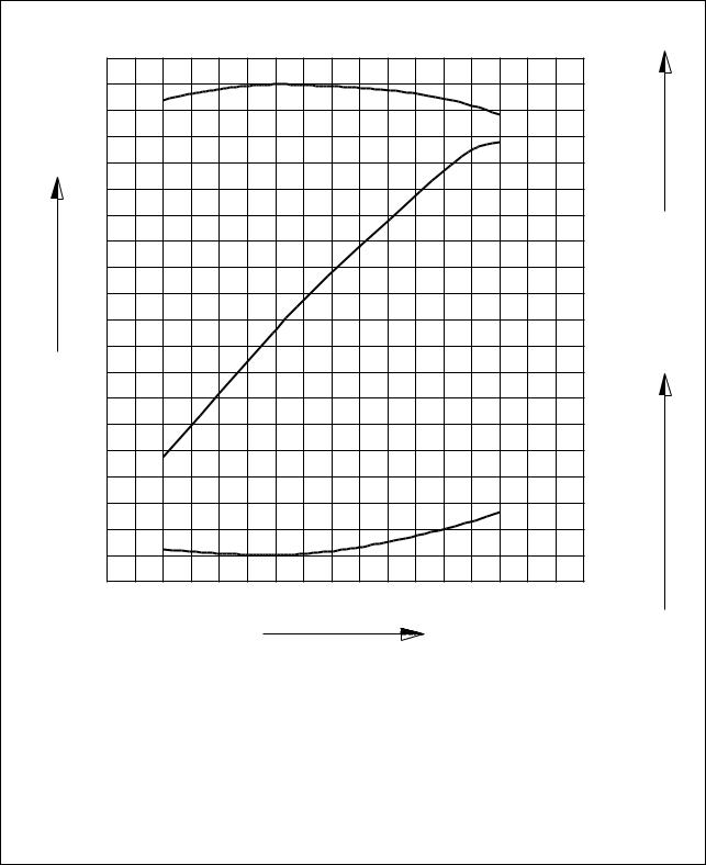
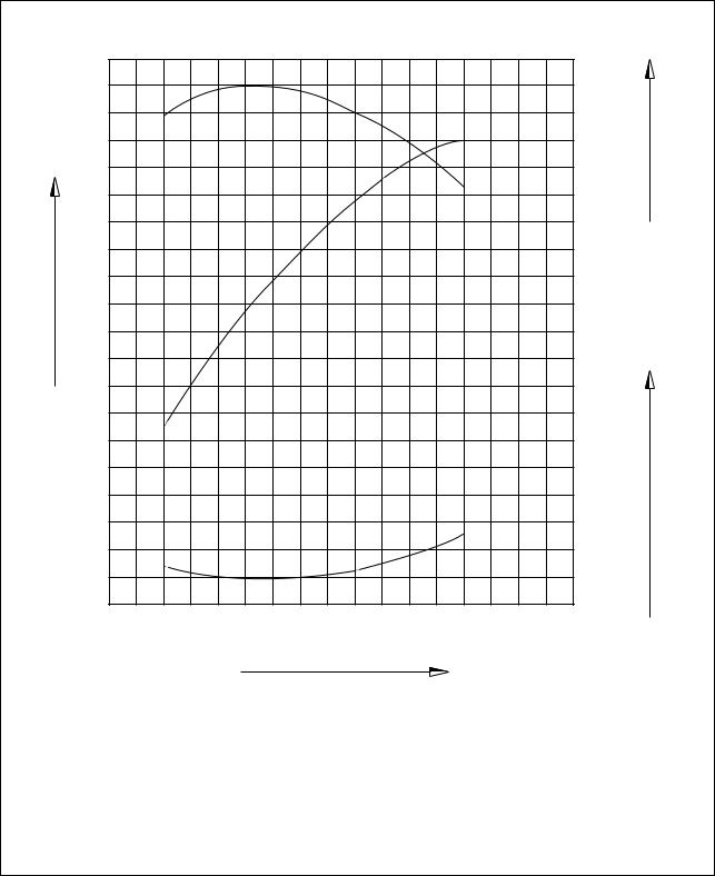
1.4. Engine performance curve
1.4.1. DE12
Output(ps)
220
200
180
160
140
120
100
|
85 |
|
|
80 |
m) |
|
. |
|
|
75 |
Torque(kg |
|
70 |
|
h) |
|
|
. |
|
|
170 |
consumption(g/ps |
|
165 |
|
|
160 |
Fuel |
|
1000 |
1200 |
1400 |
1600 |
1800 |
2000 |
2200 |
2400 |
Revolution(rpm)
|
Performance criteria |
ISO 1585(SAE J1349) |
|
Output(Max.) |
235 ps/2,200 rpm |
|
Torque(Max.) |
81.5 kg.m/1,400 rpm |
|
Fuel consumption ratio(min.) |
160 g/ps.h |
EQM1004I
— 6 —
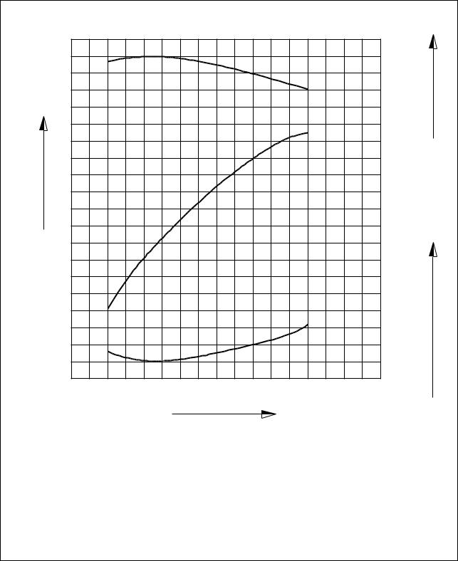
1.4.2. DE12(’98 type)
Output(ps)
220
200
180
160
140
120
100
|
1000 |
1200 |
1400 |
1600 |
1800 |
2000 |
2200 |
2400 |
Revolution(rpm)
|
h) |
|
|
. |
|
|
155 |
consumption(g/ps |
|
165 |
|
|
160 |
|
|
Fuel |
|
Performance |
ISO 1585(SAE J1349) |
|
Output(Max.) |
228 ps/2,200 rpm |
|
Torque(Max.) |
80 kg.m/1,400 rpm |
|
Fuel consumption ratio(min.) |
155 g/ps.h |
EQM1005I
— 7 —
![]()
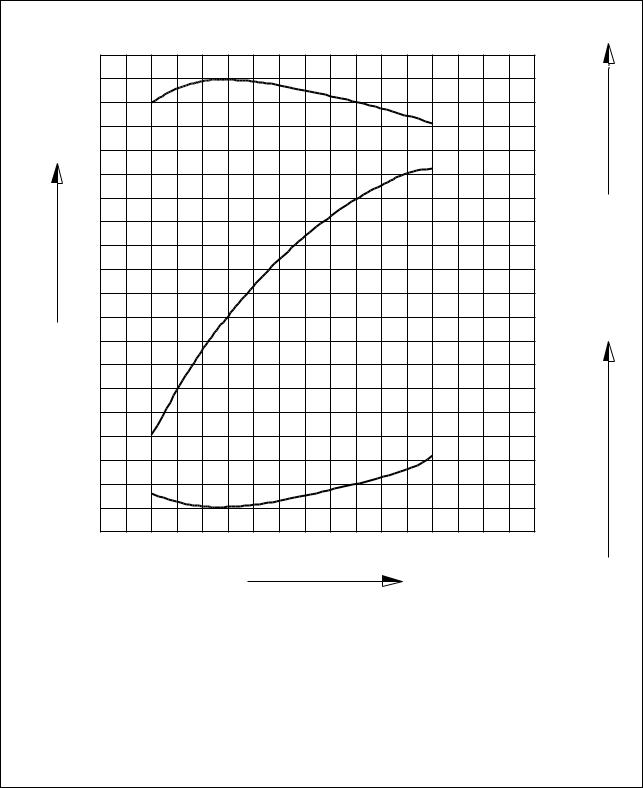
1.4.3. DE12T
Output(ps)
300
270
240
210
180
150
120
|
110 |
|
|
100 |
m) |
|
. |
|
|
90 |
Torque(kg |
|
80 |
|
h) |
|
|
. |
|
|
160 |
consumption(g/ps |
|
170 |
|
|
165 |
|
|
155 |
Fuel |
|
1 000 |
1200 |
1400 |
1600 |
1800 |
2000 |
2200 |
2400 |
Revolution(rpm)
|
Performance |
ISO 1585(SAE J1349) |
|
Output(Max.) |
300 ps/2,200 rpm |
|
Torque(Max.) |
110 kg.m/1,300 rpm |
|
Fuel consumption ratio(min.) |
155 g/ps.h |
EQM1006I
— 8 —
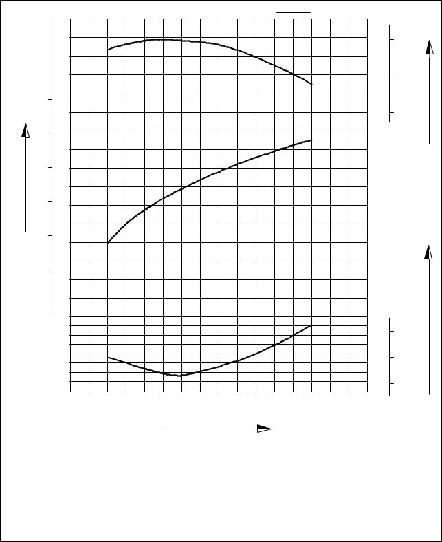
1.4.4. DE12TI
Output(ps)
340
310
280
250
220
190
160
|
135 |
|
|
130 |
m) |
|
. |
|
|
125 |
Torque(kg |
|
120 |
|
h) |
|
|
. |
|
|
155 |
consumption(g/ps |
|
160 |
|
|
150 |
Fuel |
|
1 000 |
1200 |
1400 |
1600 |
1800 |
2000 |
2200 |
2400 |
Revolution(rpm)
|
Performance |
ISO 1585(SAE J1349) |
|
Output(Max.) |
340 ps/2,100 rpm |
|
Torque(Max.) |
135 kg.m/1,260 rpm |
|
Fuel consumption ratio(min.) |
147 g/ps.h |
EQM1007I
— 9 —
1.4.5. DE12TI(280 ps : ’98 type)
Output(ps)
|
115 |
|
|
105 |
m) |
|
. |
|
|
95 |
Torque(kg |
|
h) |
|||||||||
|
. |
|||||||||
|
155 |
consumption(g/ps |
||||||||
|
150 |
|||||||||
|
145 |
Fuel |
||||||||
|
1000 |
1200 |
1400 |
1600 |
1800 |
2000 |
2200 |
2400 |
||
Revolution(rpm)
|
Performance |
ISO 1585(SAE J1349) |
|
Output(Max.) |
280 ps/2,100 rpm |
|
Torque(Max.) |
115 kg.m/1,260 rpm |
|
Fuel consumption ratio(min.) |
145 g/ps.h |
EQM1008I
— 10 —
1.4.6. DE12TI(310 ps : ’98 type)
Output(ps)
|
1000 |
1200 |
1400 |
1600 |
1800 |
2000 |
2200 |
2400 |
Revolution(rpm)
|
125 |
|
|
115 |
m) |
|
. |
|
|
105 |
Torque(kg |
|
h) |
|
|
. |
|
|
155 |
consumption(g/ps |
|
150 |
|
|
145 |
Fuel |
|
Performance |
ISO 1585(SAE J1349) |
|
Output(Max.) |
310 ps/2,100 rpm |
|
Torque(Max.) |
125 kg.m/1,260 rpm |
|
Fuel consumption ratio(min.) |
145 g/ps.h |
EQM1009I
— 11 —
1.4.7. DE12TIS
Power output(ps)
|
ps |
kW |
ISO 1585 |
kg.m |
|
|
N.m |
||||
|
1400 |
140 |
|||
|
1200 |
120 |
m) |
||
|
. |
||||
|
400 |
300 |
Torque(kg |
||
|
1000 |
100 |
|||
|
350 |
300
200
250
|
200 |
|||||||||
|
150 |
h) |
||||||||
|
100 |
|||||||||
|
. |
|||||||||
|
150 |
consumption(g/ps |
||||||||
|
g/kW.h g/ps.h |
|||||||||
|
220 |
160 |
||||||||
|
210 |
|||||||||
|
200 |
Fuel |
||||||||
|
190 |
140 |
||||||||
|
0 |
|||||||||
|
1200 |
1400 |
1600 |
1800 |
2000 |
2200 |
||||
|
1000 |
Revolution(rpm)
|
Performance |
ISO 1585(SAE J1349) |
|
Output(Max.) |
340 ps/2,100 rpm |
|
Torque(Max.) |
140 kg.m/1,260 rpm |
|
Fuel consumption ratio(min.) |
143 g/ps.h |
EA2M1002
— 12 —

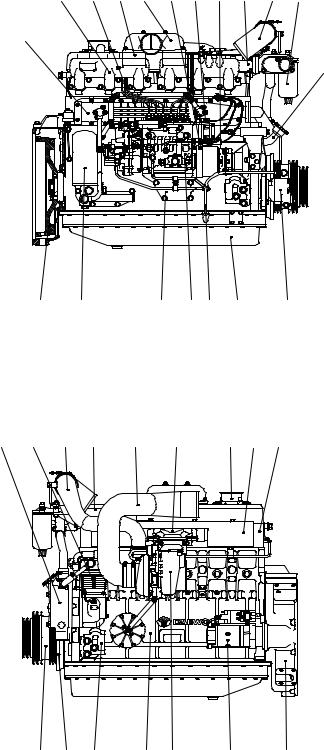
1.5. Exterior view of engine
1.5.1. DE12for Bus
|
10 |
17 |
19 |
18 |
24 |
13 |
|
4 |
1. Cylinder block |
|||||||
|
2. Flywheel housing |
||||||||
|
3. Breather |
||||||||
|
4. Oil filler pipe |
||||||||
|
5. Vibration damper |
||||||||
|
6. Flywheel |
||||||||
|
7. V-pulley |
||||||||
|
8. Cylinder head |
||||||||
|
9. Oil filter |
||||||||
|
6 |
9 |
20 |
21 |
12 |
11 |
27 7 |
10. |
Oil cooler |
|
11. |
Oil pan |
|||||||
|
12. |
Oil dipstick |
|||||||
|
13. |
Cooling water pipe |
|||||||
|
14. |
Water pump |
|||||||
|
22 |
25 |
16 |
15 |
3 |
8 |
15. |
Exhaust manifold |
|
|
16. |
Heat shield |
|||||||
|
17. |
Intake manifold |
|||||||
|
18. |
Intake stake |
|||||||
|
19. |
Injection pipe |
|||||||
|
20. |
Injection pump |
|||||||
|
21. |
Injection pump bracket |
|||||||
|
22. |
Fuel filter |
|||||||
|
23. |
Starter |
|||||||
|
24. |
Air heater |
|||||||
|
25. |
Air compressor |
|||||||
|
26. |
Mounting bracket |
|||||||
|
27. |
Power steering pump |
|
14 |
5 |
26 |
1 |
23 |
2 |
EQM1010I
— 13 —
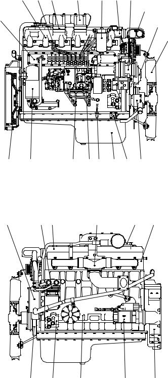
1.5.2. DE12for Truck
|
18 |
20 |
26 |
19 |
23 |
14 |
27 |
24
11
7
16
|
6 |
10 |
22 |
21 13 |
12 |
4 |
29 |
|
15 |
30 |
9 |
17 |
3 |
8 |
|
5 |
28 |
1 |
25 |
2 |
1.Cylinder block
2.Flywheel housing
3.Breather
4.Oil filler pipe
5.Vibration damper
6.Flywheel
7.Idle pulley
8.Cylinder head
9.Cylinder head cover
10.Oil filter
11.Oil cooler
12.Oil pan
13.Oil dipstick
14.Cooling water pipe
15.Water pump
16.Cooling fan
17.Exhaust manifold
18.Intake manifold
19.Intake stake
20.Injection pipe
21.Injection pump
22.Injection pump bracket
23.Fuel filter
24.Alternator
25.Starter
26.Air heater
27.Air-conditioning compressor
28.Engine mounting bracket
29.Power steering pump
30.Air compressor
EA2M1003
— 14 —
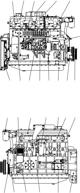
1.5.3. DE12Tfor Bus
|
10 |
16 |
20 |
18 |
25 |
13 |
4
|
6 |
9 |
21 |
22 |
12 |
11 |
28 |
7 |
|
23 |
26 |
17 |
19 |
3 |
15 |
8 |
|
14 |
5 |
27 |
1 |
24 |
2 |
EQM1011I
1.Cylinder block
2.Flywheel housing
3.Breather
4.Oil filler pipe
5.Vibration damper
6.Flywheel
7.V-pulley
8.Cylinder head
9.Oil filter
10.Oil cooler
11.Oil pan
12.Oil dipstick
13.Cooling water pipe
14.Water pump
15.Exhaust manifold
16.Intake manifold
17.Heat shield
18.Intake stake
19.Turbocharger
20.Injection pipe
21.Injection pump
22.Injection pump bracket
23.Fuel filter
24.Starter
25.Air heater
26.Air compressor
27.Mounting bracket
28.Power steering pump
— 15 —

1.5.4. DE12TI(340 ps)- for Bus
|
10 |
16 |
22 |
17 |
27 |
13 |
21 |
29
4
|
6 |
9 |
23 |
24 |
12 |
11 |
31 |
7 |
|
|
25 |
28 |
20 |
18 |
19 |
3 |
15 |
8 |
|
14 |
5 |
30 |
1 |
26 |
2 |
EQM1012I
1.Cylinder block
2.Flywheel housing
3.Breather
4.Oil filler pipe
5.Vibration damper
6.Flywheel
7.V-pulley
8.Cylinder head
9.Oil filter
10.Oil cooler
11.Oil pan
12.Oil dipstick
13.Cooling water pipe
14.Water pump
15.Exhaust manifold
16.Intake manifold
17.Intake stake
18.Turbocharger
19.Air pipe, T/C-A/P
20.Air pipe, A/P-I/C
21.Air pipe, A/P-I/C
22.Injection pipe
23.Injection pump
24.Injection pump bracket
25.Fuel filter
26.Starter
27.Air heater
28.Air compressor
29.Alternator
30.Mounting bracket
28. Power steering pump
— 16 —
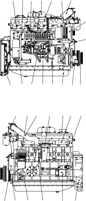
1.5.5. DE12TI(280 ps : ’98 type)- for Bus
|
10 |
16 |
21 |
17 |
26 |
13 |
20 |
28
4
|
6 |
9 |
22 |
23 |
12 |
11 |
30 |
7 |
|
24 |
27 |
19 |
18 |
3 |
15 |
8 |
|
14 |
5 |
29 |
1 |
25 |
2 |
EQM1013I
1.Cylinder block
2.Flywheel housing
3.Breather
4.Oil filler pipe
5.Vibration damper
6.Flywheel
7.V-pulley
8.Cylinder head
9.Oil filter
10.Oil cooler
11.Oil pan
12.Oil dipstick
13.Cooling water pipe
14.Water pump
15.Exhaust manifold
16.Intake manifold
17.Intake stake
18.Turbocharger
19.Air pipe, T/C-A/P
20.Air pipe, A/P-I/C
21.Injection pipe
22.Injection pump
23.Injection pump bracket
24.Fuel filter
25.Starter
26.Air heater
27.Air compressor
28.Alternator
29.Mounting bracket
30.Power steering pump
— 17 —
![]()
1.5.6. DE12TI(310 ps : ’98 type)- for Bus
|
10 |
16 |
22 |
17 |
27 |
13 |
21 |
29
4
|
6 |
9 |
23 |
24 |
12 |
11 |
31 |
7 |
|
|
25 |
28 |
20 |
18 |
19 |
3 |
15 |
8 |
|
14 |
5 |
30 |
1 |
26 |
2 |
EQM1014I
1.Cylinder block
2.Flywheel housing
3.Breather
4.Oil filler pipe
5.Vibration damper
6.Flywheel
7.V-pulley
8.Cylinder head
9.Oil filter
10.Oil cooler
11.Oil pan
12.Oil dipstick
13.Cooling water pipe
14.Water pump
15.Exhaust manifold
16.Intake manifold
17.Intake stake
18.Turbocharger
19.Air pipe, T/C-A/P
20.Air pipe, A/P-I/C
21.Air pipe, A/P-I/C
22.Injection pipe
23.Injection pump
24.Injection pump bracket
25.Fuel filter
26.Starter
27.Air heater
28.Air compressor
29.Alternator
30.Mounting bracket
31.Power steering pump
— 18 —
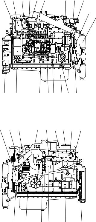
1.5.7. DE12TI — for Truck
|
11 |
27 |
19 |
24 |
30 |
20 |
14 |
28 |
31 |
7
16
|
2 |
10 |
26 |
25 13 |
12 |
4 |
33 |
|||
|
15 |
23 |
34 |
22 |
17 |
9 |
3 |
18 |
8 |
|
5 |
32 |
1 |
21 |
29 |
6 |
EA2M1004
1.Cylinder block
2.Flywheel housing
3.Breather
4.Oil filler pipe
5.Vibration damper
6.Flywheel
7.Idle pulley
8.Cylinder head
9.Cylinder head cover
10.Oil filter
11.Oil cooler
12.Oil pan
13.Oil dipstick
14.Cooling water pipe
15.Water pump
16.Cooling fan
17.Exhaust manifold
18.Heat screen
19.Intake manifold
20.Intake stake
21.Turbocharger
22.Air pipe, A/C-T/C
23.Air pipe, T/C-I/C
24.Injection pipe
25.Injection pump
26.Injection pump bracket
27.Fuel filter
28.Alternator
29.Starter
30.Air heater
31.Air-conditioning compressor
32.Engine mounting bracket
33.Power steering pump
34.Air compressor
— 19 —
1.5.8. DE12TIS — for Bus
18 24 32 19 26 27 28 14 23 30
11
4
|
6 |
10 |
12 |
29 |
25 13 |
12 |
34 |
|
15 |
35 |
22 |
9 |
21 |
16 |
3 |
17 |
8 |
|
7 |
5 |
33 |
1 |
20 |
31 |
2 |
EA2M1005
1.Cylinder block
2.Flywheel housing
3.Breather
4.Oil filler pipe
5.Vibration damper
6.Flywheel
7.Crank shaft pulley
8.Cylinder head
9.Cylinder head cover
10.Oil filter
11.Oil cooler
12.Oil pan
13.Oil dipstick
14.Cooling water pipe
15.Water pump
16.Exhaust manifold
17.Heat screen
18.Intake manifold
19.Intake stake
20.Turbocharger
21.Air pipe, A/C-T/C
22.Air pipe, T/C-A/P
23.Air pipe, A/P-I/C
24.Injection pipe
25.Injection pump
26.Pick-up sensor
27.Prestroke actuator sensor
28.Rack sensor
29.Injection pump bracket
30.Fuel filter
31.Starter
32.Air heater
33.Engine mounting bracket
34.Power steering pump
35.Air compressor
— 20 —

1.5.9. DE12TIS — for Truck
30 19 24 33 20 26 27 28 14 34
31
11
7
16
|
2 |
10 |
29 |
25 13 |
12 |
4 |
36 |
|
15 |
23 |
37 |
9 |
22 |
17 |
18 |
3 |
8 |
|
5 |
35 |
1 |
21 |
32 |
6 |
EA2M1006
1.Cylinder block
2.Flywheel housing
3.Breather
4.Oil filler pipe
5.Vibration damper
6.Flywheel
7.Idle pulley
8.Cylinder head
9.Cylinder head cover
10.Oil filter
11.Oil cooler
12.Oil pan
13.Oil dipstick
14.Cooling water pipe
15.Water pump
16.Cooling fan
17.Exhaust manifold
18.Heat screen
19.Intake manifold
20.Intake stake
21.Turbocharger
22.Air pipe, A/C-T/C
23.Air pipe, T/C-I/C
24.Injection pipe
25.Injection pump
26.Pick-up sensor
27.Prestroke actuator sensor
28.Rack sensor
29.Injection pump bracket
30.Fuel filter
31.Alternator
32.Starter
33.Air heater
34.Air-conditioning compressor
35.Engine mounting bracket
36.Power steering pump
37.Air compressor
— 21 —

2. Major maintenance
2.1. Preventive maintenance
2.1.1.Cooling water
1)Check the coolant level of the radiator by removing the radiator filler cap, and add coolant if necessary.
2)Check the pressure valve opening pressure using a radiator cap tester. Replace the radiator filler cap assembly if the measured value does not reach the specified limit.
3)When injecting antifreeze solution, first drain out the old coolant from the cylinder block and radiator, and then clean them with cleaning solution.
4)Be sure to mix soft water with antifreeze solution .
5)A proportion of antifreeze is represented as the ratio of antifreeze in volume, and antifreeze must be added according to each ambient temperature as described below:
|
Antifreeze solution(%) |
Freezing point(C) |
|
20 |
-10 |
|
27 |
-15 |
|
33 |
-20 |
|
40 |
-25 |
|
44 |
-30 |
|
50 |
-40 |
 CAUTION
If you add antifreeze in excess of 50% in volume, the engine may be overheated. Avoid this.
As the individual freezing points corresponding to the above proportions of antifreeze are subject to change slightly according to the kind of antifreeze, you must follow the specifications provided by the antifreeze manufacturer.
6)When the ratio of antifreeze in the mixture decreases new coolant should be added to make up for the loss in old coolant resulting from engine operation, check the mix ratio with every replenishment of coolant, and top up as necessary.
7)To prevent corrosion or air bubbles in the coolant path, be sure to add a specific additive, i.e. corrosion inhibitor, to the coolant.
•Type : DAC65L
•Mix ratio : 1.5M of inhibitor to 50M of coolant
(Namely, add corrosion inhibitor amounting to 3% of water capacity.)
 Add antifreeze of at least 5% in volume to prevent possible engine corrosion in hot weather.
— 22 —
2.1.2.Fan belt
1)Use a fan belt of specified dimensions, and replace if damaged, frayed, or deteriorated.
2)Check the fan belt for belt tension. If belt tension is lower than the specified limit, adjust the tension by relocating the alternator and air conditioner. (Specified deflection: 10~15mm when pressed down with thumb)
2.1.3.Engine oil
1)Check oil level using the oil dipstick and replenish if necessary.
2)Check the oil level with the vehicle stationary on a level ground, engine cooled. The oil level must be between MAX and MIN lines on the stick.
3)Engine oil should be changed at the specified intervals. Oil in the oil filter also should be changed simultaneously.
(First oil change : 1,000km running)
• Suggested engines oils
|
Engine Model |
SAE NO. |
API NO |
|
DE12, DE12T,DE12TI |
15W40 |
CD grade or above |
|
DE12TIS |
15W40 |
CG grade |
2.1.4.Oil filter
1)Check for oil pressure and oil leaks, and repair or replace the oil filter if necessary.
2)Change the oil filter element simultaneously at every replacement of engine oil.
2.1.5.Fuel filter
1)Drain water in cartridge with losen the cock under filter from time to time.
2)The fuel filter should be replaced at every 20,000km
2.1.6.Air cleaner
1)Replace any deformed or broken element or cracked air cleaner.
2)Clean or replace the element at regular intervals
— 23 —
2.1.7.Valve clearance
1)Turn the crank shaft so that the piston in No. 1 cylinder reaches the TDC on compression
stroke, then adjust the valve clearance.
2)After releasing the lock nut for the rocker arm adjusting screw, insert a feeler gauge of specified thickness into the clearance between the rocker arm and valve stem, and adjust the clearance with the adjusting screw. Fully tighten the lock nut when a correct adjustment is obtained.
3)Carry out the same adjusting operation according to the firing order(1-5-3-6-2-4) (Valve clearance(with engine cooled): 0.30mm for both intake and exhaust)
2.1.8.Cylinder compression pressure
1)Stop the engine after warming up, then remove the nozzle holder assembly.
2)Install a special tool(gauge adapter) in nozzle holder hole and mount the compression gauge in position of the nozzle holder.
|
Standard |
28 kg/cm2 over |
|
Limit |
24 kg/cm2 or less |
|
Difference between each cylinder |
L10% or less |
3)Cut off fuel circulation, rotate the starter, then measure compression pressure in each cylinder.
6Testing conditions: Coolant temperature 20C, Engine speed, 200 rpm (10 turns)
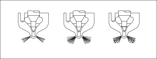
2.1.9.Injection nozzle
1)Assemble a nozzle to a nozzle tester.
2)Check injection pressure, and adjust the nozzle using the adjusting shim if the pressure does not meet the specified limit.
3)Check nozzle spray patterns and replace if damaged.
EFM1006I
<Figure 2-1> Nozzle spray patterns
— 24 —
2.1.10.Fuel injection pump
1)Check the fuel injection pump housing for cracks or breaks, and replace if damaged.
2)Check and see if the lead seal for idling control and speed control levers have not been removed.
2.1.11.Battery
1)Check the battery for damage or leaking of battery fluid(electrolyte) from cracks on the battery. Replace the battery if damaged.
2)Check battery fluid level and add distilled water if necessary.
3)Measure the specific gravity of the electrolyte in the battery. Recharge the battery if the hydrometer readings are lower than the specified limit(1.12~1.28)
— 25 —

2.2. Diagnostics and trouble shooting for the engine
2.2.1. Diagnostics
1. Engine won’t start
|
Starter does not turn |
Starter |
turns but engine does not start |
|||||||||||||||||||||||||||||||||||||
|
Check battery fluid and specific gravity |
Engine |
Fuel |
|||||||||||||||||||||||||||||||||||||
|
Normal |
Too low |
Check air cleaner |
Check fuel level |
||||||||||||||||||||||||||||||||||||
|
Replenish or recharge |
Normal |
Fouled |
Normal |
No fuel |
|||||||||||||||||||||||||||||||||||
|
Check cable connections |
Replace or clean element |
Replenish |
|||||||||||||||||||||||||||||||||||||
|
Normal |
Replenish or recharge |
Check compression pressure |
Check fuel injection |
||||||||||||||||||||||||||||||||||||
|
Check starter s/w |
Normal |
Too low |
Normal |
No fuel injection |
|||||||||||||||||||||||||||||||||||
|
Normal |
Replenish or recharge |
Retighten or replace |
Air bleeding and re-start |
||||||||||||||||||||||||||||||||||||
|
Check starter relay |
Check other parts |
Check injection timing |
|||||||||||||||||||||||||||||||||||||
|
Normal |
Replace |
Check valve clearance |
Normal |
Adjust |
|||||||||||||||||||||||||||||||||||
|
Check magnetic s/w |
Normal |
Adjust |
Check injection nozzle(injection |
||||||||||||||||||||||||||||||||||||
|
pressure, injection condition, etc.) |
|||||||||||||||||||||||||||||||||||||||
|
Normal |
Replenish or recharge |
Check cylinder head gasket |
|||||||||||||||||||||||||||||||||||||
|
Normal |
Repair or replace |
||||||||||||||||||||||||||||||||||||||
|
Disassemble and check starter motor |
Normal |
Replace |
|||||||||||||||||||||||||||||||||||||
|
Disassemble and check |
|||||||||||||||||||||||||||||||||||||||
|
Overhaul the engine |
injection pump |
||||||||||||||||||||||||||||||||||||||
|
(valve assembly, cylinder |
|||||||||||||||||||||||||||||||||||||||
|
liner, piston, etc.) |
|||||||||||||||||||||||||||||||||||||||
|
Check fuel feed pump for function |
|||||||||||||||||
|
Normal |
Check feed pump valve and strainer |
Air in the fuel |
|||||||||||||||
|
Disassemble and check injection pump |
Normal |
Clean or replace |
Retighten the joint and/or replace gasket |
||||||||||||||
|
Check fuel filter |
Air bleeding |
||||||||||||||||
|
Dirty element and/or overflow valve faulty |
Continuous entry of air in fuel system |
||||||||||||||||
|
Replace |
Disassemble and check feed pump |
||||||||||||||||
— 26 —

2. Engine overheating
|
Cooling system |
Fuel system |
Operating conditions |
||||||||||||||||||||||||||||||||||||
|
1. Overload |
||||||||||||||||||||||||||||||||||||||
|
2. Clogged radiator core |
||||||||||||||||||||||||||||||||||||||
|
3. Continued overrunning |
||||||||||||||||||||||||||||||||||||||
|
Check coolant level |
Check fuel quality |
|||||||||||||||||||||||||||||||||||||
|
Normal |
Too low |
Bad |
||||||||||||||||||||||||||||||||||||
|
Check fan belt for tension, wear, or breaks |
Clean or replace with the specified fuel |
|||||||||||||||||||||||||||||||||||||
|
Normal |
Repair or replace |
|||||||||||||||||||||||||||||||||||||
|
Check radiator cap |
Replenish |
Check water pump |
||||||||||||||||||||||||||||||||||||
|
Normal |
Replace |
External |
Internal |
|||||||||||||||||||||||||||||||||||
|
Check thermostat |
Retighten or repair |
Overhaul engine |
||||||||||||||||||||||||||||||||||||
|
Normal |
Replace |
|||||||||||||||||||||||||||||||||||||
|
Excessive fuel rate |
||||||||||||||||||||||||||||||||||||||
|
Check radiator |
||||||||||||||||||||||||||||||||||||||
|
Check injection nozzles |
||||||||||||||||||||||||||||||||||||||
|
Normal |
Damaged |
|||||||||||||||||||||||||||||||||||||
|
Normal |
Abnormal |
|||||||||||||||||||||||||||||||||||||
|
Repair or replace |
||||||||||||||||||||||||||||||||||||||
|
Repair or replace |
||||||||||||||||||||||||||||||||||||||
|
Clean coolant path |
||||||||||||||||||||||||||||||||||||||
|
Adjust or repair injection pump |
||||||||||||||||||||||||||||||||||||||
Check water pump
|
Normal |
Repair or replace |
|||
Overhaul the engine
— 27 —
![]()
3. Lack of power
|
Engine |
Chassis |
||||||||||||||||||||||
|
Fuel system |
Others |
Check for clutch slip |
|||||||||||||||||||||
|
Check fuel line for air |
Check air cleaner |
Adjust or replace clutch |
|||||||||||||||||||||
|
Check fuel feed pump |
Normal |
Clean or replace |
|||||||||||||||||||||
|
Normal |
Clean or replace |
Check engine control rod, link and |
|||||||||||||||||||||
|
cable |
|||||||||||||||||||||||
|
Check fuel filter element and overflow valve |
|||||||||||||||||||||||
|
Normal |
Adjust |
||||||||||||||||||||||
|
Normal |
Replace |
||||||||||||||||||||||
|
Check valve clearance |
|||||||||||||||||||||||
Check injection piping
|
Normal |
Repair or replace |
|||
Check injection nozzle(injection pressure, nozzle spray patterns, etc.)
|
Normal |
Adjust |
||
Check cylinder head gasket for break
|
Normal |
Replace |
|||
|
Normal |
Adjust or replace |
Overhaul engine(valve assembly) |
|||
Check injection timing
Normal 
 Adjust
Overhaul engine or injection pump
— 28 —

4. Low oil pressure
Check if oil pressure gauge indicates exactly
Check oil level
|
Normal |
Too low |
|||||||||||
|
Check cooling water temperature |
Refill with recommanded oil |
|||||||||||
|
Normal |
Too high |
|||||||||||
|
Check oil quality |
Refer to ‘Engine overheating’ |
|||||||||||
|
Normal |
||||||||||||
|
Check oil pressure relief valve |
Water, fuel, etc. mixed in oil |
Inadequate |
|||||||
|
Normal |
Adjust or replace |
Overhaul engine or injection pump |
Replace with suggested lub. oil |
||||||
|
Overhaul the engine |
|||||||||
— 29 —

5. High fuel consumption
Causes according to operating conditions
1.Overload
2.Frequent use of low gear position at high speed
3.Frequent use of high gear position at low speed
4.Clutch slip
5.Too low tire inflation pressure
Check fuel leakage
Normal
Check injection nozzle (injection pressure, spray patterns, etc.)
Normal
Check injection timing
Normal
Check compression pressure
|
Normal |
Check valve clearance |
|||||||||
|
Disassemble injection pump |
||||||||||
|
Repair or replace |
||||||||||
|
Cylinder liner |
||||||||||
|
Piston ring |
||||||||||
|
Normal |
Adjust |
|||||||||
|
Piston |
||||||||||
|
Check head gasket |
||||||||||
|
Normal |
Replace |
|||||||||
|
Overhaul engine |
||||||||||
|
(valve assembly, piston, |
||||||||||
|
cylinder liner, etc.) |
||||||||||
Oil leakage
Retighten or replace
— 30 —

6. Excessive oil consumption
Causes according to operating conditions
1.Too high lub. oil level
2.Continuous driving at low speed or with excessive cold engine
Check oil leakage
Check air cleaner
Clean or replace
|
Normal |
Oil leak |
|||||||||
|
Check oil quality |
External |
Internal |
||||||||
|
Replace with suggested lub. oil |
Retighten or replace |
Check compression pressure |
||||||||
Overhaul engine
(piston, cyl. liner)
Normal
Disassemble cylinder head(valve stem seal)
— 31 —

7. Engine knocks(excessive)
Check fuel and oil burning(Check carbon deposit from exhaust gas)
|
Not identified |
Identified |
|||||||||||||||||||||||
|
Check compression pressure |
Overhaul engine |
|||||||||||||||||||||||
|
Normal |
Too low |
|||||||||||||||||||||||
|
Check injection timing |
Check valve clearance, cyl. |
|||||||||||||||||||||||
|
head gasket for damage |
||||||||||||||||||||||||
|
Normal |
Adjust |
|||||||||||||||||||||||
|
Normal |
Replace or adjust |
|||||||||||||||||||||||
|
Check fuel quality |
||||||||||||||||||||||||
Overhaul engine
Use suggested fuel
— 32 —

8. Dead or weak battery
|
Battery |
Harness, switch |
Alternator |
|||||||||||||
|
Check battery fluid level |
Check wiring connections |
Check fan belt for |
|||||||||||||
|
for short, etc |
deflection, damage, etc. |
||||||||||||||
|
Repair or replace |
|||||||||||||||
|
Normal |
|||||||||||||||
|
Check battery fluid specs. |
Damaged battery case |
Battery discharged |
Battery overcharged |
||||||||||||
|
Replenish |
Replace |
Recharge |
Check alternator and |
||||||||||||
|
voltage regulator |
|||||||||||||||
Normal
Check charging condition
Discharged
Disassemble alternator and regulator
Abnormal
Adjust or replace
— 33 —

2.2.2. Trouble shooting
|
Complaint |
Cause |
Correction |
|
|
1) Difficulty in engine |
|||
|
starting |
|||
|
(1) Trouble in starter |
(See <2.2.1>) |
||
|
(2) Trouble in fuel system |
(See <Section 4.3 Fuel system>) |
Check valve and valve seat, |
|
|
(3) Lack of compression |
1 |
Valves holding open, skewed valve stem |
then repair or replace |
|
pressure |
2 |
Valve springs damaged |
Replace valve springs |
|
3 |
Leaky cylinder head gasket |
Replace gasket |
|
|
4 |
Worn pistons, piston ring, or liner |
Replace |
|
|
2) Rough engine idling |
|||
|
1 |
Wrong injection timing |
Adjust |
|
|
2 |
Air in injection pump |
Air bleeding |
|
|
3) Lack of engine power |
|||
|
(1) Engine continues to |
1 |
Valve clearance incorrect |
Adjust |
|
lack power |
2 |
Valve poorly seated |
Repair |
|
3 |
Leaky cylinder head gasket |
Replace gasket |
|
|
4 |
Piston rings worn, sticking, or |
Replace piston rings |
|
|
damaged |
|||
|
5 |
Injection timing incorrect |
Adjust |
|
|
6 |
Volume of fuel delivery insufficient |
Adjust injection pump |
|
|
7 |
Nozzle injection pressure incorrect |
Adjust or replace nozzles |
|
|
or nozzles seized |
|||
|
8 |
Feed pump faulty |
Repair or replace |
|
|
9 |
Restrictions in fuel pipes |
Repair |
|
|
10 |
Volume of intake air insufficient |
Clean or replace air cleaner |
|
|
(2) Engine lacks power on |
1 |
Compression pressure insufficient |
Overhaul engine |
|
acceleration |
2 |
Injection timing incorrect |
Adjust |
|
3 |
Volume of fuel delivery insufficient |
Adjust injection pump |
|
|
4 |
Injection pump timer faulty |
Repair or replace |
|
|
5 |
Nozzle injection pressure or spray |
Repair or replace |
|
|
angle incorrect |
|||
|
6 |
Feed pump faulty |
Repair or replace |
|
|
7 |
Volume of intake air insufficient |
Clean or replace air cleaner |
|
|
4) Engine overheating |
|||
|
1 |
Lack of engine oil or poor oil |
Replenish or replace |
|
|
2 |
Lack of coolant |
Replenish or replace |
|
|
3 |
Fan belts slipping, worn or damaged |
Adjust or replace |
|
|
4 |
Water pump faulty |
Repair or replace |
|
|
5 |
Thermostat inoperative |
Replace |
|
|
6 |
Valve clearance incorrect |
Adjust |
|
|
7 |
Back pressure in exhaust line |
Clean or replace |
|
— 34 —

|
Complaint |
Cause |
Correction |
|
|
5) Engine noises |
|||
|
It is important to correctly locate the |
|||
|
causes of noise since generally nois- |
|||
|
es may originate from various engine |
|||
|
components such as rotating parts, |
|||
|
sliding parts, etc. |
|||
|
(1) Crankshaft |
1 |
Oil clearance excessive due to |
Replace bearings and grind |
|
worn bearings or crankshaft |
crankshaft |
||
|
2 |
Crankshaft worn out-of-round |
Grind or replace crankshaft |
|
|
3 |
Restrictions in oil ports and resul- |
Clean oil path |
|
|
tant lack of oil supply |
Replace bearings and grind |
||
|
4 |
Bearings seized up |
crankshaft |
|
|
(2) Conn. rod and conn. |
|||
|
1 |
Conn. rod bearings worn out-of- |
Replace bearings |
|
|
rod bearings |
round |
||
|
2 |
Crank pin worn out-of-round |
Grind crankshaft |
|
|
3 |
Conn. rod skewed |
Repair or replace |
|
|
4 |
Bearings seized up |
Replace bearings and grind |
|
|
crankshaft |
|||
|
5 |
Restrictions in oil ports and resul- |
Clean oil path |
|
|
tant lack of oil supply |
|||
|
(3) Pistons, piston pins, |
|||
|
1 |
Piston clearance excessive due to |
Replace pistons and piston |
|
|
and piston rings |
worn piston and piston rings |
rings |
|
|
2 |
Piston or piston pin worn |
Replace pistons and piston |
|
|
rings |
|||
|
3 |
Piston seized up |
Replace pistons |
|
|
4 |
Piston poorly seated |
Replace pistons |
|
|
5 |
Piston rings damaged |
Replace piston rings |
|
|
(4) Others |
|||
|
1 |
Crankshaft and/or thrust bearing |
Replace thrust bearings |
|
|
worn |
|||
|
2 |
Camshaft end play excessive |
Replace thrust plate |
|
|
3 |
Idle gear end play excessive |
Replace thrust washers |
|
|
4 |
Timing gear backlash excessive |
Adjust or replace |
|
|
5 |
Valve clearance excessive |
Adjust valve clearance |
|
|
6 |
Tappets and cams worn |
Replace tappets and camshaft |
|
|
6) Excessive fuel |
1 |
Injection timing incorrect |
Adjust |
|
consumption |
2 |
Volume of fuel injection excessive |
Adjust injection pump |
|
3 |
Tire under-inflated |
Adjust |
|
|
4 |
Gear selection inadequate(frequent |
Select gears correctly accord- |
|
|
use of low gears) |
ing to load |
||
— 35 —

|
Complaint |
Cause |
Correction |
|
|
7) High oil consumption |
|||
|
(1) Oil leaking into |
1 |
Clearance between cylinder liner |
Replace |
|
combustion chamber |
and piston excessive |
||
|
2 |
Piston rings and ring grooves |
Replace pistons and piston |
|
|
worn excessively |
rings |
||
|
3 |
Piston rings broken, worn, or sticking |
Replace piston rings |
|
|
4 |
Piston rings gaps set incorrectly |
Correct |
|
|
5 |
Piston skirt portion broken, worn |
Replace pistons |
|
|
excessively |
|||
|
6 |
Oil return holes in oil control ring |
Replace piston rings |
|
|
restricted |
|||
|
7 |
Oil ring seated incorrectly |
Replace piston rings |
|
|
8 |
Breather piping restricted |
Clean or replace |
|
|
(2) Oil leaking past cylinder |
|||
|
1 |
Valve stems and valve guide |
Replace as complete set |
|
|
head |
loose excessively |
||
|
2 |
Valve stem seals worn |
Replace seals |
|
|
3 |
Leaky cylinder head gasket |
Replace gasket |
|
|
(3) Oil leaks |
|||
|
1 |
Applicable parts loosened |
Replace or repair gasket |
|
|
2 |
Applicable packings worn |
Replace packings |
|
|
3 |
Oil seals worn |
Replace oil seals |
|
— 36 —

3. Disassembly and reassembly of major components
3.1. Disassembly
3.1.1.General precautions
1)Maintenance operation should be carried out in a bright and clean place.
2)Before disassembly, provide parts racks for storage of various tools and disassembled parts.
3)Arrange the disassembled parts in the disassembly sequence and take care to prevent any damage to them.
3.1.2.Engine oil
1)Take out the oil dipstick.
2)Remove the drain plug from the oil pan and drain out the engine oil into a container.
3)Reassemble the drain plug with the oil pan after draining out the engine oil.
3.1.3. Cooling water
1)Remove the drain plug from the cylinder block and drain out the cooling water into a container.
3.1.4.Fan belt
1)Remove the fan guide and bracket.
2)Loosen the tension adjusting nuts installed on the alternator and air-condi- tioning compressor, and take off the fan belt.
EQM3003I
— 37 —
![]()
3.1.5. Cooling fan
1)Remove the flange fixing bolts, then take off the flange and cooling fan.
3.1.6.Oil level gauge guide tube
1)Loosen the flange nut installed on the ladder frame to remove the guide tube.
3.1.7.Alternator
1)Loosen the alternator fixing bolts to disassemble the alternator, then remove the tension adjusting bolt and bracket.
|
EQM3006I |
|
|
3.1.8. Air-conditioning compressor |
|
|
1) |
Remove the compressor fixing bolts and |
|
disassemble the A/C compressor. |
|
|
2) |
Disassemble the A/C compressor ten- |
|
sion adjusting bolt and alternator fixing |
|
|
bracket. |
|
|
3) |
Disassemble the A/C compressor fixing |
|
bracket. |
|
|
EQM3007I |
|
|
— 38 — |

3.1.9.Fuel filter
1)Remove fuel hoses connected to the fuel injection pump, take off the bracket fixing bolts, then disassemble the fuel filter.
3.1.10.Breather
1)Loosen the clamp screw to remove the rubber hose.
3.1.11.Injection pipe
1)Unscrew the hollow screws to disassemble the fuel return pipe.
2)Remove the nuts installed on the fuel injection pump and nozzles, then disassemble the injection pipe.
3.1.12. Air heater
1)Remove the electrical wiring for the air heater.
2)Disassemble the intake pipes by loosening the nuts installed thereon.
3)Disassemble the air heater and gasket.
3.1.13. Intake manifold
1)Remove the air hose connected to the fuel injection pump.
2)Loosen the intake manifold fixing bolts, then disassemble the intake manifold.

3.1.14.Turbocharger (for DE12T / DE12TI / DE12TIS only)
1)Release the clamp screw of the rubber hose connected to the intake manifold, and take off the intake pipes both simultaneously.
2)Unscrew the exhaust pipe bracket fixing bolts, release the nuts installed on the turbocharger, then disassemble the exhaust pipe.
3)Remove the turbocharger after removing the oil supply pipe and return pipe and releasing the fixing nuts.
3.1.15. Exhaust manifold
1) Release the exhaust manifold fixing bolts, disassemble the exhaust manifold, then remove the heat shield and gasket.
Note : Make sure to release the nuts one after another because the exhaust manifold will be removed if you unscrew the two nuts simultaneously.
3.1.16. Starter
1)Unscrew the starter fixing bolts, then disassemble the starter.
3.1.17. Thermostat
1)Remove the by-pass pipe connected to the water pump, unscrew the thermostat fixing bolts, then dissemble the thermostat assembly.
2)Disassemble the thermostat housing and remove the thermostat.
3)Disassemble the water pipe by unscrewing the bolts and nuts installed on the cylinder head.

3.1.18. Fuel injection pump
1)Remove the oil supply pipe and return pipe connected to the fuel injection pump.
2)Unscrew the bolts connecting the coupling and drive shaft, loosen the injec-
tion pump attaching bolts, then disassemble the injection pump.
Note : Place the No.1 cylinder in the
exact ‘OT’ position to disassem-
ble the injection pump.
3)Release the pump fixing bracket bolts to disassemble the bracket from the
cylinder block.
Note : Do not interchange the shims as
they must be installed in their
original positions at reassembly.
3.1.19. Oil filter
1)Using a filter remover, remove the filter element.
2)Remove the pipe connected to the oil cooler.
3)Loosen the oil filter fixing bolts and disassemble the oil filter head from the cylinder block.
EQM3018S
3.1.20. Idle pulley
1)Remove the bolts and disassemble the idle pulley.
EQM3019S
— 41 —

3.1.21. Power steering pump
1)Remove the oil hoses.
2)Unscrew the hex bolts and remove the steering pump.
EQM3020S
3.1.22. Water pump
1)Remove the water pipe connected to the expansion tank
2)Remove the water pipe and hoses connected to the water pump.
3)Unscrew the water pump fixing bolts and remove the water pump.
EQM3021S
3.1.23. Air compressor
1)Remove the oil hose, water pipe, air pipe connected to the air compressor, remove the air cooler fixing bolts, then disassemble the air compressor from the timing gear case.
EQM3022S
3.1.24. Vibration damper
1)Unscrew the pulley fixing bolts and disassemble the pulley-vibration damper assembly.
2)Unscrew the vibration damper fixing bolts and disassemble the damper from the pulley.
EQM3023S
— 42 —

3.1.25. Timing gear case cover
1)Disassemble the oil seal using an oil seal removing jig.
2)Remove the cover fixing bolts and disassemble the cover from the timing gear case.
3.1.26. Idle gear
1)Unscrew the idle gear fixing bolts and disassemble the thrust washer and idle gear.
2)Disassemble the idle gear pin using a rubber hammer to prevent damage to them.
3.1.27. Fuel injection pump drive assembly
1)Remove the dowel pin for the steering pump.
2)Unscrew the injection pump drive shaft bearing housing fixing bolts and remove the injection pump drive assembly in which the shaft, gear, bearings, and housing are put together.
3.1.28. Cylinder head cover
1)Unscrew the cover fixing bolts and disassemble the cover.
2)Keep the bolts in an assembly state so that the packings and washers may not be lost, and keep the cover packing as assembled with the cover.

3.1.29. Rocker arm assembly
1)Unscrew the rocker arm bracket bolts and remove the rocker arm assembly.
2)Take off the snap rings to remove the washers and rocker arm, then unscrew the bracket fixing bolts to take off the bracket and springs.
3)Take out the push rods.
3.1.30. Injection nozzle
1)Remove the nozzle fixing nuts and extract the nozzles.
2)Remove the nozzle tube using nozzle tube removing jig.
Do not perform disassembly opera-
tion unless coolant, gas, etc. leak
out.
3.1.31. Cylinder head
1)Unscrew the cylinder head fixing bolts and take off the cylinder head.
2)Remove the cylinder head gasket.
3.1.32. Valve and valve stem seal
1)Compress the valve spring retainer using a jig and take off the valve cotter pin.
2)Disassemble the valve springs and retainer.
3)Take off the valve.
4)Remove and discard the valve stem seal using a general tool as it should not be re-used.
EQM3029I
Compress the spring
EJM3027S
— 44 —

3.1.33. Oil cooler
1)Remove the water pipe connected to the water pump.
2)Unscrew the oil cooler cover fixing bolts and disassemble the oil cooler assembly from the cylinder block.
3)Unscrew the oil cooler fixing bolts and remove the oil cooler from the oil cooler cover.
3.1.34. Oil pan
1)Stand the engine with the flywheel housing facing toward the bottom.
2)Release the oil pan fixing bolts, remove the stiffeners, then disassemble the oil pan.
3.1.35. Oil pump and oil pipe
1)Unscrew the oil inlet pipe bracket bolts, releasing the pipe fixing bolts, then disassemble the oil suction pipe assembly.
2)Disassemble the oil pipe feeding oil from the oil pump to the cylinder block.
3)Unscrew the oil pump fixing bolts and disassemble the oil pump.
3.1.36. Ladder frame
1) Disassemble the ladder frame.

3.1.37. Piston and connection rod
1) Disassemble the pistons by two hands while turning the crankshaft.
2)Unscrew the conn. rod fixing bolts and take off the pistons and conn. rods in the direction of piston.
EQM3035I
3)Remove the piston pin snap rings, take off the piston pin, then disconnect the conn. rod from the piston.
|
EQM3036S |
||
|
4) |
Disassemble the piston rings using ring |
|
|
pliers. |
||
|
5) |
Take care not to interchange the disas- |
|
|
sembled parts and keep them in the |
Piston ring jig |
|
|
sequence of cylinder No. |
EQM3037S
3.1.38. Cylinder liner
1) Take off the cylinder liner.
EQM3038I
— 46 —

3.1.39. Flywheel
1)Position the engine so that the head installing surface of the cylinder block faces down.
2)Unscrew the flywheel fixing bolts and fit a dowel pin.
3)Install flywheel disassembling bolts in the bolt holes machined on the flywheel, and disassemble the flywheel.
3.1.40. Oil seal
1)Take off the rear oil seal using an oil seal disassembling jig.
2)If only the inside guide ring is removed, use a general tool to take off the outside seal.
3.1.41. Flywheel housing
1)Loosen the housing fixing bolts and disassemble the flywheel housing.
|
EQM3041I |
|
|
3.1.42. Cam shaft and tappet |
|
|
1) |
Remove the cam shaft gear. |
|
2) |
Take off the cam shaft gear thrust |
|
washer. |
|
|
3) |
Take out the cam shaft carefully not to |
|
damage the cam shaft. |
|
|
4) |
Slide out the tappets by hand. |
|
EQM3042I |
|
|
— 47 — |
 Loading…
Содержание
- Doosan DE12T Operation & Maintenance Manual
- Quick Links
- Related Manuals for Doosan DE12T
- Summary of Contents for Doosan DE12T
- Page 3: Table Of Contents
- Page 5: Safety Regulations
- Page 7: Regulations Designed To Prevent Pollution
- Page 9: General Information
- Page 13: Engine Specification
- Page 14: Technical Information
- Page 15: Engine Type
- Page 16: Engine Timing
- Page 17: Lubrication System
- Page 25: Electrical Equipment
- Page 27: Commissioning And Operation
- Page 29: Operation In Winter Time
- Page 30: Tuning The Engine
- Page 31: Maintenance And Care
- Page 34: Cooling System
- Page 39: Fuel System
- Page 43: Turbocharger
- Page 45: Checking And Setting
- Page 48: Cylinder Compression Pressure
- Page 51: Operation Tip
- Page 59: Causes And Remedies
- Page 62: General Information
- Page 63: Engine Characteristics
- Page 64: Disassembly And Reassembly Of Major Components
- Page 77: Inspection
- Page 116: Breaking-In
- Page 117: Maintenance Of Major Components
- Page 121: Fuel Injection Pump
Doosan DE12T Operation & Maintenance Manual
Quick Links
Summary of Contents for Doosan DE12T
- Page 2 /P126TI /P126TI-1/DE12T. The POLUS means ‘Power Plus’ that is represented more powerful Doosan generating-set engines and it is marked on engine name as an initial P. On the other hand, intial D stands for standard engine prior to POLUS version.
Page 3: Table Of Contents
Page 5: Safety Regulations
Page 7: Regulations Designed To Prevent Pollution
Page 9: General Information
Page 13: Engine Specification
Page 14: Technical Information
Page 15: Engine Type
Page 16: Engine Timing
Page 17: Lubrication System
0.855 Flash Point D 93 100 (38) 125 (52) 131 (55) û.
15mm between the fan pulley and 15mm the alternator pulley in normal condition. For Alternator the adjustment of the tension, loosen the Pulley Pulley adjusting bolts which support the alternator.
Page 25: Electrical Equipment
Page 27: Commissioning And Operation
Page 29: Operation In Winter Time
Page 30: Tuning The Engine
Page 31: Maintenance And Care
Page 34: Cooling System
Page 39: Fuel System
3 turns until draining occurs.
Page 43: Turbocharger
Page 45: Checking And Setting
Page 48: Cylinder Compression Pressure
8.5 kg . m Torque ¥ Install the oil delivery pipe and return pipe. 6.3.
Page 51: Operation Tip
Page 59: Causes And Remedies
Page 62: General Information
Page 63: Engine Characteristics
Page 64: Disassembly And Reassembly Of Major Components
Page 77: Inspection
Tension at 37mm 61.8 kg.
59.88 mm 59.52 mm Use a micrometer to measure the cam journal diameter. I II If the measured number is less than the I II specified limit, camshaft.
83.092 mm Standard Dia.
3.41 kg 2nd ring 2.0
3.0 kg Oil ring 4.03
5.57 kg 9.2.10.
2 threads (3) Third stage : With torque wrench, tighten at about 15 kg.m (4) Fourth stage : With torque wrench, tighten up to about 22 kg.m (5) Fifth stage : Finally, tighten in the specified torque 28kg.m with torque wrench .
8.5 kg EAMD021I ¥ Install the oil delivery pipe and return pipe.
Page 116: Breaking-In
Page 117: Maintenance Of Major Components
85 C) and improves thermal efficiency of the engine by preventing heat loss. Namely, when the temperature of coolant Bypass is low, the thermostat valve is closed to valve.
Page 120 10.1.4. Diagnostics and troubleshooting Complaints Possible causes Corrections ¥ ¥ 1. Engine overheating Lack of coolant Replenish coolant ¥ ¥ Radiator cap pressure Replace cap valve spring weakened ¥ ¥ Fan belt loosened or Adjust or replace fan belt broken ¥.
Page 121: Fuel Injection Pump
7.5 K Hz continuous Speed Drift with Temperature . ±0.5% Maximum Idle Adjust CW . 60% of set speed Idle Adjust CCW . É.É. Less than 1200Hz Droop Range . É..ÉÉ.
450 kgf/cm to fully.
8.0 kg . m Tightening torque EQM4036I ¥.
- Manuals
- Brands
- Doosan Manuals
- Engine
- DE12TIS
Manuals and User Guides for Doosan DE12TIS. We have 1 Doosan DE12TIS manual available for free PDF download: Operation & Maintenance Manual
Doosan DE12TIS Operation & Maintenance Manual (158 pages)
DIESEL VEHICLE ENGINE
Brand: Doosan
|
Category: Engine
|
Size: 8.03 MB
Table of Contents
-
Table of Contents
5
-
1 General Information
7
-
General Repair Instructions
7
-
Engine Characteristics
8
-
Engine Specifications
9
-
Engine Assembly
18
-
-
2 Major Maintenance
25
-
Preventive Maintenance
25
-
Diagnosis and Remedy
33
-
Engine Inspection
43
-
-
3 Disassembly and Reassembly of Major Components
44
-
Disassembly
44
-
Inspection and Measurement
58
-
Reassembly
73
-
Breaking-In
95
-
-
4 Maintenance of Major Components
97
-
Cooling System
97
-
Lubricating System
102
-
Fuel Injection Pump
106
-
Turbocharger
138
-
-
Appendix
146
-
Parts & after Service Center
156
-
Advertisement
Advertisement
Related Products
-
Doosan DE12T
-
Doosan DE12 Series
-
Doosan DE12TI
-
Doosan DE08TS
-
Doosan DE08TIS Series
-
Doosan DE08TIS PBL00
-
Doosan DE08TIS MBE00
-
Doosan DB33A
-
Doosan DP180LBS
-
Doosan D15S-5
Doosan Categories
Air Compressor
Engine
Excavators
Forklifts
Industrial Equipment
More Doosan Manuals
Производим диагностику, обслуживание и ремонт техники Doosan Solar Daewoo, документация:
AD086TI
Дизельный двигатель DAEWOO AD086TI Инструкция по ремонту
AD126TI
Дизельный двигатель DAEWOO AD126TI Каталог запасных частей
AD126TI
Дизельный двигатель DAEWOO AD126TI Инструкция по ремонту
AD136
Дизельный двигатель DAEWOO AD136 Инструкция по ремонту
AD136T
Дизельный двигатель DAEWOO AD136T Инструкция по ремонту
AD136TI
Дизельный двигатель DAEWOO AD136TI Инструкция по ремонту
AD196T
Дизельный двигатель DAEWOO AD196T Каталог запасных частей
AD196T
Дизельный двигатель DAEWOO AD196T Инструкция по ремонту
AD196TI
Дизельный двигатель DAEWOO AD196TI Каталог запасных частей
AD196TI
Дизельный двигатель DAEWOO AD196TI Инструкция по ремонту
D1146
Дизельный двигатель DAEWOO D1146 Каталог запасных частей
D1146
Дизельный двигатель DAEWOO D1146 Инструкция по ремонту
D1146T
Дизельный двигатель DAEWOO D1146T Каталог запасных частей
D1146T
Дизельный двигатель DAEWOO D1146T Инструкция по ремонту
D1146TI
Дизельный двигатель DAEWOO D1146TI Каталог запасных частей
D1146TI
Дизельный двигатель DAEWOO D1146TI Инструкция по ремонту
D427
Дизельный двигатель DAEWOO D427 Каталог запасных частей
D427
Дизельный двигатель DAEWOO D427 Инструкция по ремонту
D430
Дизельный двигатель DAEWOO D430 Инструкция по ремонту
D436
Дизельный двигатель DAEWOO D436 Инструкция по ремонту
D2366
Дизельный двигатель DAEWOO D2366 Инструкция по ремонту
D2366T
Дизельный двигатель DAEWOO D2366T Инструкция по ремонту
DB33
Дизельный двигатель DAEWOO DB33 Каталог запасных частей
DB33
Дизельный двигатель DAEWOO DB33 Инструкция по эксплуатации
DB33
Дизельный двигатель DAEWOO DB33 Инструкция по ремонту
DB33A
Дизельный двигатель DAEWOO DB33A Инструкция по ремонту
DB58
Дизельный двигатель DAEWOO DB58 Каталог запасных частей
DB58
Дизельный двигатель DAEWOO DB58 Инструкция по ремонту
DB58S
Дизельный двигатель DAEWOO DB58S Каталог запасных частей
DB58S
Дизельный двигатель DAEWOO DB58S Инструкция по ремонту
DB58T
Дизельный двигатель DAEWOO DB58T Инструкция по ремонту
DB58TI
Дизельный двигатель DAEWOO DB58TI Инструкция по ремонту
DB58TIS
Дизельный двигатель DAEWOO DB58TIS Каталог запасных частей
DB58TIS
Дизельный двигатель DAEWOO DB58TIS Инструкция по ремонту
DC24
Дизельный двигатель DAEWOO DC24 Инструкция по ремонту
DE08TIS
Дизельный двигатель DAEWOO DE08TIS Каталог запасных частей
DE08TIS
Дизельный двигатель DAEWOO DE08TIS Инструкция по ремонту
DE08TS Tier II
Дизельный двигатель DAEWOO DE08TS Tier II Инструкция по ремонту
DE12
Дизельный двигатель DAEWOO DE12 Инструкция по ремонту
DE12T
Дизельный двигатель DAEWOO DE12T Каталог запасных частей
DE12T
Дизельный двигатель DAEWOO DE12T Инструкция по ремонту
DE12TI
Дизельный двигатель DAEWOO DE12TI Инструкция по ремонту
DE12TIA
Дизельный двигатель DAEWOO DE12TIA Инструкция по ремонту
DE12TIS
Дизельный двигатель DAEWOO DE12TIS Каталог запасных частей
DE12TIS
Дизельный двигатель DAEWOO DE12TIS Инструкция по ремонту
DL06
Дизельный двигатель DAEWOO DL06 Каталог запасных частей
DL06
Дизельный двигатель DAEWOO DL06 Инструкция по ремонту
DL06 Tier III
Дизельный двигатель DAEWOO DL06 Tier III Инструкция по ремонту
DL08
Дизельный двигатель DAEWOO DL08 Каталог запасных частей
DL08
Дизельный двигатель DAEWOO DL08 Инструкция по ремонту
DL08 Euro-IV
Дизельный двигатель DAEWOO DL08 Euro-IV Каталог запасных частей
DL08 Euro-IV
Дизельный двигатель DAEWOO DL08 Euro-IV Инструкция по ремонту
DL08K
Дизельный двигатель DAEWOO DL08K Каталог запасных частей
DL08S
Дизельный двигатель DAEWOO DL08S Каталог запасных частей
DL08S
Дизельный двигатель DAEWOO DL08S Инструкция по ремонту
DL08TIS
Дизельный двигатель DAEWOO DL08TIS Каталог запасных частей
DV11
Дизельный двигатель DAEWOO DV11 Каталог запасных частей
DV11
Дизельный двигатель DAEWOO DV11 Инструкция по ремонту
DV11 Euro-IV
Дизельный двигатель DAEWOO DV11 Euro-IV Инструкция по ремонту
DV11K
Дизельный двигатель DAEWOO DV11K Каталог запасных частей
DV15
Дизельный двигатель DAEWOO DV15 Инструкция по ремонту
DV15T
Дизельный двигатель DAEWOO DV15T Инструкция по ремонту
DV15TI
Дизельный двигатель DAEWOO DV15TI Инструкция по ремонту
DV15TIS
Дизельный двигатель DAEWOO DV15TIS Инструкция по ремонту
L086TI
Дизельный двигатель DAEWOO L086TI Инструкция по ремонту
L126TI
Дизельный двигатель DAEWOO L126TI Каталог запасных частей
L126TI
Дизельный двигатель DAEWOO L126TI Инструкция по ремонту
L126TIM
Дизельный двигатель DAEWOO L126TIM Каталог запасных частей
L136
Дизельный двигатель DAEWOO L136 Инструкция по ремонту
L136T
Дизельный двигатель DAEWOO L136T Инструкция по ремонту
L136TI
Дизельный двигатель DAEWOO L136TI Инструкция по ремонту
MD196T
Дизельный двигатель DAEWOO MD196T Каталог запасных частей
MD196T
Дизельный двигатель DAEWOO MD196T Инструкция по ремонту
MD196TI
Дизельный двигатель DAEWOO MD196TI Каталог запасных частей
MD196TI
Дизельный двигатель DAEWOO MD196TI Инструкция по ремонту
P034TI
Дизельный двигатель DAEWOO P034TI Каталог запасных частей
P034TI
Дизельный двигатель DAEWOO P034TI Инструкция по эксплуатации
P034TI
Дизельный двигатель DAEWOO P034TI Инструкция по ремонту
P086TI
Дизельный двигатель DAEWOO P086TI Каталог запасных частей
P086TI
Дизельный двигатель DAEWOO P086TI Инструкция по ремонту
P086TI-1
Дизельный двигатель DAEWOO P086TI-1 Каталог запасных частей
P126TI
Дизельный двигатель DAEWOO P126TI Каталог запасных частей
P126TI
Дизельный двигатель DAEWOO P126TI Инструкция по ремонту
P126TI-1
Дизельный двигатель DAEWOO P126TI-1 Каталог запасных частей
P126TI-1
Дизельный двигатель DAEWOO P126TI-1 Инструкция по ремонту
P126TI-II
Дизельный двигатель DAEWOO P126TI-II Каталог запасных частей
P126TI-II
Дизельный двигатель DAEWOO P126TI-II Инструкция по ремонту
P129TI-1
Дизельный двигатель DAEWOO P129TI-1 Каталог запасных частей
P158FE
Дизельный двигатель DAEWOO P158FE Инструкция по ремонту
P158LE
Дизельный двигатель DAEWOO P158LE Инструкция по ремонту
P158LE-1
Дизельный двигатель DAEWOO P158LE-1 Инструкция по ремонту
P158LE-2
Дизельный двигатель DAEWOO P158LE-2 Инструкция по ремонту
P158LE-III
Дизельный двигатель DAEWOO P158LE-III Инструкция по ремонту
P158LE-S
Дизельный двигатель DAEWOO P158LE-S Каталог запасных частей
P158LE-S
Дизельный двигатель DAEWOO P158LE-S Инструкция по ремонту
P180FE
Дизельный двигатель DAEWOO P180FE Инструкция по ремонту
P180LE
Дизельный двигатель DAEWOO P180LE Инструкция по ремонту
P180LE-1
Дизельный двигатель DAEWOO P180LE-1 Инструкция по ремонту
P180LE-II
Дизельный двигатель DAEWOO P180LE-II Инструкция по ремонту
P180LE-S
Дизельный двигатель DAEWOO P180LE-S Каталог запасных частей
P180LE-S
Дизельный двигатель DAEWOO P180LE-S Инструкция по ремонту
P222FE
Дизельный двигатель DAEWOO P222FE Каталог запасных частей
P222FE
Дизельный двигатель DAEWOO P222FE Инструкция по ремонту
P222LE
Дизельный двигатель DAEWOO P222LE Каталог запасных частей
P222LE
Дизельный двигатель DAEWOO P222LE Инструкция по ремонту
P222LE-1
Дизельный двигатель DAEWOO P222LE-1 Инструкция по ремонту
P222LE-II
Дизельный двигатель DAEWOO P222LE-II Инструкция по ремонту
P222LE-S
Дизельный двигатель DAEWOO P222LE-S Инструкция по ремонту
PU034
Дизельный двигатель DAEWOO PU034 Каталог запасных частей
PU066
Дизельный двигатель DAEWOO PU066 Каталог запасных частей
PU066
Дизельный двигатель DAEWOO PU066 Инструкция по ремонту
PU086
Дизельный двигатель DAEWOO PU086 Каталог запасных частей
PU086
Дизельный двигатель DAEWOO PU086 Инструкция по ремонту
PU086T
Дизельный двигатель DAEWOO PU086T Каталог запасных частей
PU086T
Дизельный двигатель DAEWOO PU086T Инструкция по ремонту
PU086TI
Дизельный двигатель DAEWOO PU086TI Каталог запасных частей
PU158TI
Дизельный двигатель DAEWOO PU158TI Инструкция по ремонту
PU180TI
Дизельный двигатель DAEWOO PU180TI Инструкция по ремонту
PU222TI
Дизельный двигатель DAEWOO PU222TI Инструкция по ремонту
G420
LPG двигатель DAEWOO G420 Инструкция по ремонту
G420E
LPG двигатель DAEWOO G420E Каталог запасных частей
G420E
LPG двигатель DAEWOO G420E Инструкция по ремонту
G420F
LPG двигатель DAEWOO G420F Каталог запасных частей
G420F LP
LPG двигатель DAEWOO G420F LP Инструкция по ремонту
G420FE
LPG двигатель DAEWOO G420FE Каталог запасных частей
G420FE LP
LPG двигатель DAEWOO G420FE LP Инструкция по ремонту
G424
LPG двигатель DAEWOO G424 Каталог запасных частей
G424
LPG двигатель DAEWOO G424 Инструкция по ремонту
G424E
LPG двигатель DAEWOO G424E Каталог запасных частей
G424E
LPG двигатель DAEWOO G424E Инструкция по ремонту
G424LP
LPG двигатель DAEWOO G424LP Каталог запасных частей
G424 LP
LPG двигатель DAEWOO G424 LP Инструкция по ремонту
G424F LP
LPG двигатель DAEWOO G424F LP Каталог запасных частей
G424F LP
LPG двигатель DAEWOO G424F LP Инструкция по ремонту
G424FE LP
LPG двигатель DAEWOO G424FE LP Каталог запасных частей
G424FE LP
LPG двигатель DAEWOO G424FE LP Инструкция по ремонту
G430E
LPG двигатель DAEWOO G430E Каталог запасных частей
G430E
LPG двигатель DAEWOO G430E Инструкция по ремонту
G430 LP
LPG двигатель DAEWOO G430 LP Каталог запасных частей
G430 LP
LPG двигатель DAEWOO G430 LP Инструкция по ремонту
G439E
LPG двигатель DAEWOO G439E Каталог запасных частей
G643E
LPG двигатель DAEWOO G643E Инструкция по ремонту
G643 LP
LPG двигатель DAEWOO G643 LP Каталог запасных частей
G643 LP
LPG двигатель DAEWOO G643 LP Инструкция по ремонту
G643E LP
LPG двигатель DAEWOO G643E LP Каталог запасных частей
G643E LP
LPG двигатель DAEWOO G643E LP Инструкция по ремонту
Hercules 2.7
LPG двигатель DAEWOO Hercules 2.7 Инструкция по ремонту
GE08TI
Газовый двигатель DAEWOO GE08TI Каталог запасных частей
GE08TI
Газовый двигатель DAEWOO GE08TI Инструкция по ремонту
GE08TIC
Газовый двигатель DAEWOO GE08TIC Каталог запасных частей
GE08TIC
Газовый двигатель DAEWOO GE08TIC Инструкция по ремонту
GE12TI
Газовый двигатель DAEWOO GE12TI Каталог запасных частей
GE12TI
Газовый двигатель DAEWOO GE12TI Инструкция по ремонту
GE12TIC
Газовый двигатель DAEWOO GE12TIC Каталог запасных частей
GE12TIC
Газовый двигатель DAEWOO GE12TIC Инструкция по ремонту
GL08K
Газовый двигатель DAEWOO GL08K Каталог запасных частей
GL08K
Газовый двигатель DAEWOO GL08K Инструкция по ремонту
GV158TI
Газовый двигатель DAEWOO GV158TI Каталог запасных частей
GV158TIC
Газовый двигатель DAEWOO GV158TIC Каталог запасных частей
GV158TIC
Газовый двигатель DAEWOO GV158TIC Инструкция по ремонту
GV180TI
Газовый двигатель DAEWOO GV180TI Каталог запасных частей
GV180TIC
Газовый двигатель DAEWOO GV180TIC Каталог запасных частей
GV180TIC
Газовый двигатель DAEWOO GV180TIC Инструкция по ремонту
GV222TI
Газовый двигатель DAEWOO GV222TI Каталог запасных частей
GV222TIC
Газовый двигатель DAEWOO GV222TIC Каталог запасных частей
GV222TIC
Газовый двигатель DAEWOO GV222TIC Инструкция по ремонту
H20-II
Газовый двигатель DAEWOO H20-II Инструкция по ремонту
1340XL
Погрузчик с бортовым поворотом DAEWOO 1340XL Инструкция по ремонту
1550XL
Погрузчик с бортовым поворотом DAEWOO 1550XL Комплект гидравлических и электрических схем
1760XL
Погрузчик с бортовым поворотом DAEWOO 1760 XL Каталог запасных частей
1760XL
Погрузчик с бортовым поворотом DAEWOO 1760XL Комплект гидравлических и электрических схем
2060XL
Погрузчик с бортовым поворотом DAEWOO 2060XL Комплект гидравлических и электрических схем
430
Погрузчик с бортовым поворотом DAEWOO 430 Каталог запасных частей
430
Погрузчик с бортовым поворотом DAEWOO 430 Инструкция по эксплуатации и обслуживанию
430
Погрузчик с бортовым поворотом DAEWOO 430 Инструкция по ремонту
430 Plus
Погрузчик с бортовым поворотом DAEWOO 430 Plus Каталог запасных частей
430 Plus
Погрузчик с бортовым поворотом DAEWOO 430 Plus Инструкция по эксплуатации и обслуживанию
430 Plus
Погрузчик с бортовым поворотом DAEWOO 430 Plus Инструкция по ремонту
440 Plus
Погрузчик с бортовым поворотом DAEWOO 440 Plus Каталог запасных частей
440 Plus
Погрузчик с бортовым поворотом DAEWOO 440 Plus Инструкция по эксплуатации и обслуживанию
440 Plus
Погрузчик с бортовым поворотом DAEWOO 440 Plus Инструкция по ремонту
450
Погрузчик с бортовым поворотом DAEWOO 450 Каталог запасных частей
450
Погрузчик с бортовым поворотом DAEWOO 450 Инструкция по эксплуатации и обслуживанию
450
Погрузчик с бортовым поворотом DAEWOO 450 Инструкция по ремонту
450 Plus
Погрузчик с бортовым поворотом DAEWOO 450 Plus Каталог запасных частей
450 Plus Tier-3
Погрузчик с бортовым поворотом DAEWOO 450 Plus Tier-3 Каталог запасных частей
450 Plus
Погрузчик с бортовым поворотом DAEWOO 450 Plus Инструкция по эксплуатации и обслуживанию
450 Plus
Погрузчик с бортовым поворотом DAEWOO 450 Plus Инструкция по ремонту
460
Погрузчик с бортовым поворотом DAEWOO 460 Каталог запасных частей
460
Погрузчик с бортовым поворотом DAEWOO 460 Инструкция по эксплуатации и обслуживанию
460
Погрузчик с бортовым поворотом DAEWOO 460 Инструкция по ремонту
460 Plus
Погрузчик с бортовым поворотом DAEWOO 460 Plus Каталог запасных частей
460 Plus Tier-3
Погрузчик с бортовым поворотом DAEWOO 460 Plus Tier-3 Каталог запасных частей
460 Plus
Погрузчик с бортовым поворотом DAEWOO 460 Plus Инструкция по эксплуатации и обслуживанию
460 Plus
Погрузчик с бортовым поворотом DAEWOO 460 Plus Инструкция по ремонту
470 Plus
Погрузчик с бортовым поворотом DAEWOO 470 Plus Каталог запасных частей
470 Plus
Погрузчик с бортовым поворотом DAEWOO 470 Plus Инструкция по эксплуатации и обслуживанию
DSL601
Погрузчик с бортовым поворотом DAEWOO DSL601 Каталог запасных частей
DSL602
Погрузчик с бортовым поворотом DAEWOO DSL602 Каталог запасных частей
DSL602
Погрузчик с бортовым поворотом DAEWOO DSL602 Инструкция по ремонту
DSL702
Погрузчик с бортовым поворотом DAEWOO DSL702 Каталог запасных частей
DSL702
Погрузчик с бортовым поворотом DAEWOO DSL702 Комплект гидравлических и электрических схем
DSL802
Погрузчик с бортовым поворотом DAEWOO DSL802 Каталог запасных частей
DSL802
Погрузчик с бортовым поворотом DAEWOO DSL802 Комплект гидравлических и электрических схем
DSL902
Погрузчик с бортовым поворотом DAEWOO DSL902 Каталог запасных частей
DSL902
Погрузчик с бортовым поворотом DAEWOO DSL902 Комплект гидравлических и электрических схем
DD80
Бульдозер DAEWOO DD80 Каталог запасных частей
DD80L
Бульдозер DAEWOO DD80L Инструкция по эксплуатации и обслуживанию
DA30
Сочлененный самосвал DAEWOO DA30 Каталог запасных частей
DA30
Сочлененный самосвал DAEWOO DA30 Инструкция по ремонту
DA30-5
Сочлененный самосвал DAEWOO DA30-5 Инструкция по ремонту
DA40
Сочлененный самосвал DAEWOO DA40 Каталог запасных частей
DA40
Сочлененный самосвал DAEWOO DA40 Инструкция по ремонту
DA40-5
Сочлененный самосвал DAEWOO DA40-5 Инструкция по ремонту
HA250-1
Сочлененный самосвал MOXY HA250-1 Каталог запасных частей
HA250-1
Сочлененный самосвал MOXY HA250-1 Инструкция по ремонту
HA250-3
Сочлененный самосвал MOXY HA250-3 Каталог запасных частей
HA250-3
Сочлененный самосвал MOXY HA250-3 Инструкция по ремонту
HA270-1
Сочлененный самосвал MOXY HA270-1 Каталог запасных частей
HA270-1
Сочлененный самосвал MOXY HA270-1 Инструкция по ремонту
HA270-3
Сочлененный самосвал MOXY HA270-3 Каталог запасных частей
HA270-3
Сочлененный самосвал MOXY HA270-3 Инструкция по ремонту
MT25
Сочлененный самосвал MOXY MT25 Каталог запасных частей
MT25
Сочлененный самосвал MOXY MT25 Инструкция по эксплуатации и обслуживанию
MT25
Сочлененный самосвал MOXY MT25 Нормы времени на ремонт
MT26
Сочлененный самосвал MOXY MT26 Каталог запасных частей
MT26
Сочлененный самосвал MOXY MT26 Инструкция по эксплуатации и обслуживанию
MT26
Сочлененный самосвал MOXY MT26 Инструкция по ремонту
MT26
Сочлененный самосвал MOXY MT26 Нормы времени на ремонт
MT26 SERIES III
Сочлененный самосвал MOXY MT26 SERIES III Каталог запасных частей
MT26 SERIES III
Сочлененный самосвал MOXY MT26 SERIES III Инструкция по эксплуатации и обслуживанию
MT27
Сочлененный самосвал MOXY MT27 Инструкция по ремонту
MT27
Сочлененный самосвал MOXY MT27 Нормы времени на ремонт
MT30
Сочлененный самосвал MOXY MT30 Каталог запасных частей
MT30
Сочлененный самосвал MOXY MT30 Инструкция по ремонту
MT30
Сочлененный самосвал MOXY MT30 Нормы времени на ремонт
MT30R
Сочлененный самосвал MOXY MT30R Инструкция по ремонту
MT30S
Сочлененный самосвал MOXY MT30S Каталог запасных частей
MT30S
Сочлененный самосвал MOXY MT30S Инструкция по ремонту
MT31
Сочлененный самосвал MOXY MT31 Каталог запасных частей
MT31
Сочлененный самосвал MOXY MT31 Инструкция по эксплуатации и обслуживанию
MT31
Сочлененный самосвал MOXY MT31 Инструкция по ремонту
MT31
Сочлененный самосвал MOXY MT31 Нормы времени на ремонт
MT31 SERIES III
Сочлененный самосвал MOXY MT31 SERIES III Каталог запасных частей
MT31 SERIES III
Сочлененный самосвал MOXY MT31 SERIES III Инструкция по эксплуатации и обслуживанию
MT31 SERIES III
Сочлененный самосвал MOXY MT31 SERIES III Инструкция по ремонту
MT36
Сочлененный самосвал MOXY MT36 Каталог запасных частей
MT36
Сочлененный самосвал MOXY MT36 Инструкция по эксплуатации и обслуживанию
MT36
Сочлененный самосвал MOXY MT36 Инструкция по ремонту
MT36
Сочлененный самосвал MOXY MT36 Нормы времени на ремонт
MT36 SERIES 2
Сочлененный самосвал MOXY MT36 SERIES 2 Инструкция по эксплуатации и обслуживанию
MT40
Сочлененный самосвал MOXY MT40 Инструкция по ремонту
MT40B
Сочлененный самосвал MOXY MT40B Каталог запасных частей
MT40B
Сочлененный самосвал MOXY MT40B Инструкция по эксплуатации и обслуживанию
MT40B
Сочлененный самосвал MOXY MT40B Инструкция по ремонту
MT40B
Сочлененный самосвал MOXY MT40B Нормы времени на ремонт
MT40B SERIES 2
Сочлененный самосвал MOXY MT40B SERIES 2 Инструкция по эксплуатации и обслуживанию
MT41
Сочлененный самосвал MOXY MT41 Каталог запасных частей
MT41
Сочлененный самосвал MOXY MT41 Инструкция по эксплуатации и обслуживанию
MT41
Сочлененный самосвал MOXY MT41 Инструкция по ремонту
DH30
Гусеничный экскаватор DAEWOO DH30 Комплект гидравлических и электрических схем
DH50
Гусеничный экскаватор DAEWOO DH50 Комплект гидравлических и электрических схем
DH70
Гусеничный экскаватор DAEWOO DH70 Каталог запасных частей
DH130
Гусеничный экскаватор DAEWOO DH130 Комплект гидравлических и электрических схем
DH130W
Гусеничный экскаватор DAEWOO DH130W Комплект гидравлических и электрических схем
DH130-2
Гусеничный экскаватор DAEWOO DH130-2 Комплект гидравлических и электрических схем
DH170
Гусеничный экскаватор DAEWOO DH170 Комплект гидравлических и электрических схем
DH180
Гусеничный экскаватор DAEWOO DH180 Комплект гидравлических и электрических схем
DH220
Гусеничный экскаватор DAEWOO DH220 Комплект гидравлических и электрических схем
DH200W
Гусеничный экскаватор DAEWOO DH200W Комплект гидравлических и электрических схем
DH220LC
Гусеничный экскаватор DAEWOO DH220LC Комплект гидравлических и электрических схем
DH280LC
Гусеничный экскаватор DAEWOO DH280LC Комплект гидравлических и электрических схем
DH320LC
Гусеничный экскаватор DAEWOO DH320LC Комплект гидравлических и электрических схем
DH450
Гусеничный экскаватор DAEWOO DH450 Комплект гидравлических и электрических схем
DX15
Гусеничный экскаватор DAEWOO DX15 Каталог запасных частей
DX15
Гусеничный экскаватор DAEWOO DX15 Инструкция по ремонту
DX18
Гусеничный экскаватор DAEWOO DX18 Каталог запасных частей
DX18
Гусеничный экскаватор DAEWOO DX18 Инструкция по ремонту
DX19
Гусеничный экскаватор DAEWOO DX19 Инструкция по ремонту
DX27Z
Гусеничный экскаватор DAEWOO DX27Z Каталог запасных частей
DX27Z
Гусеничный экскаватор DAEWOO DX27Z Инструкция по ремонту
DX30Z
Гусеничный экскаватор DAEWOO DX30Z Каталог запасных частей
DX30Z
Гусеничный экскаватор DAEWOO DX30Z Инструкция по ремонту
DX35Z
Гусеничный экскаватор DAEWOO DX35Z Каталог запасных частей
DX35Z
Гусеничный экскаватор DAEWOO DX35Z Инструкция по ремонту
DX55
Гусеничный экскаватор DAEWOO DX55 Каталог запасных частей
DX55
Гусеничный экскаватор DAEWOO DX55 Инструкция по эксплуатации и обслуживанию
DX55
Гусеничный экскаватор DAEWOO DX55 Инструкция по ремонту
DX60R
Гусеничный экскаватор DAEWOO DX60R Каталог запасных частей
DX60R
Гусеничный экскаватор DAEWOO DX60R Инструкция по ремонту
DX62R-3
Гусеничный экскаватор DAEWOO DX62R-3 Каталог запасных частей
DX62R-3
Гусеничный экскаватор DAEWOO DX62R-3 Инструкция по ремонту
DX63-3
Гусеничный экскаватор DAEWOO DX63-3 Каталог запасных частей
DX63-3
Гусеничный экскаватор DAEWOO DX63-3 Инструкция по ремонту
DX80R
Гусеничный экскаватор DAEWOO DX80R Каталог запасных частей
DX80R
Гусеничный экскаватор DAEWOO DX80R Инструкция по ремонту
DX85R-3
Гусеничный экскаватор DAEWOO DX85R-3 Каталог запасных частей
DX85R-3
Гусеничный экскаватор DAEWOO DX85R-3 Инструкция по ремонту
DX140LC
Гусеничный экскаватор DAEWOO DX140LC Каталог запасных частей
DX140LC
Гусеничный экскаватор DAEWOO DX140LC Инструкция по эксплуатации и обслуживанию
DX140LC
Гусеничный экскаватор DAEWOO DX140LC Инструкция по ремонту
DX140LC-3
Гусеничный экскаватор DAEWOO DX140LC-3 Каталог запасных частей
DX140LC-3
Гусеничный экскаватор DAEWOO DX140LC-3 Инструкция по ремонту
DX140LC-5
Гусеничный экскаватор DAEWOO DX140LC-5 Инструкция по ремонту
DX140LCR
Гусеничный экскаватор DAEWOO DX140LCR Каталог запасных частей
DX140LCR
Гусеничный экскаватор DAEWOO DX140LCR Инструкция по ремонту
DX140LCR-3
Гусеничный экскаватор DAEWOO DX140LCR-3 Каталог запасных частей
DX140LCR-3
Гусеничный экскаватор DAEWOO DX140LCR-3 Инструкция по ремонту
DX140R
Гусеничный экскаватор DAEWOO DX140R Инструкция по ремонту
DX160LC
Гусеничный экскаватор DAEWOO DX160LC Каталог запасных частей
DX160LC-3
Гусеничный экскаватор DAEWOO DX160LC-3 Каталог запасных частей
DX160LC-3
Гусеничный экскаватор DAEWOO DX160LC-3 Инструкция по ремонту
DX180LC
Гусеничный экскаватор DAEWOO DX180LC Каталог запасных частей
DX180LC
Гусеничный экскаватор DAEWOO DX180LC Инструкция по эксплуатации и обслуживанию
DX180LC
Гусеничный экскаватор DAEWOO DX180LC Инструкция по ремонту
DX180LC-3
Гусеничный экскаватор DAEWOO DX180LC-3 Каталог запасных частей
DX180LC-3
Гусеничный экскаватор DAEWOO DX180LC-3 Инструкция по ремонту
DX210
Гусеничный экскаватор DAEWOO DX210 Каталог запасных частей
DX210
Гусеничный экскаватор DAEWOO DX210 Инструкция по ремонту
DX220AF
Гусеничный экскаватор DAEWOO DX220AF Каталог запасных частей
DX225LC
Гусеничный экскаватор DAEWOO DX225LC Каталог запасных частей
DX225LC
Гусеничный экскаватор DAEWOO DX225LC Инструкция по эксплуатации и обслуживанию
DX225LC
Гусеничный экскаватор DAEWOO DX225LC Инструкция по ремонту
DX225LC-3
Гусеничный экскаватор DAEWOO DX225LC-3 Каталог запасных частей
DX225LC-3
Гусеничный экскаватор DAEWOO DX225LC-3 Инструкция по ремонту
DX225LC-5
Гусеничный экскаватор DAEWOO DX225LC-5 Инструкция по ремонту
DX225LCA
Гусеничный экскаватор DAEWOO DX225LCA Каталог запасных частей
DX225LCA
Гусеничный экскаватор DAEWOO DX225LCA Инструкция по эксплуатации и обслуживанию
DX225LCA
Гусеничный экскаватор DAEWOO DX225LCA Инструкция по ремонту
DX225LCB
Гусеничный экскаватор DAEWOO DX225LCB Каталог запасных частей
DX225LCB
Гусеничный экскаватор DAEWOO DX225LCB Инструкция по ремонту
DX225NLC
Гусеничный экскаватор DAEWOO DX225NLC Каталог запасных частей
DX225NLC
Гусеничный экскаватор DAEWOO DX225NLC Инструкция по эксплуатации и обслуживанию
DX225NLC
Гусеничный экскаватор DAEWOO DX225NLC Инструкция по ремонту
DX230LC
Гусеничный экскаватор DAEWOO DX230LC Каталог запасных частей
DX230LC
Гусеничный экскаватор DAEWOO DX230LC Инструкция по ремонту
DX235LCR
Гусеничный экскаватор DAEWOO DX235LCR Каталог запасных частей
DX235LCR
Гусеничный экскаватор DAEWOO DX235LCR Инструкция по ремонту
DX235LCR-5
Гусеничный экскаватор DAEWOO DX235LCR-5 Инструкция по ремонту
DX235NLC
Гусеничный экскаватор DAEWOO DX235NLC Каталог запасных частей
DX235NLC
Гусеничный экскаватор DAEWOO DX235NLC Инструкция по ремонту
DX235NLC-5
Гусеничный экскаватор DAEWOO DX235NLC-5 Инструкция по ремонту
DX255LC
Гусеничный экскаватор DAEWOO DX255LC Каталог запасных частей
DX255LC
Гусеничный экскаватор DAEWOO DX255LC Инструкция по эксплуатации и обслуживанию
DX255LC
Гусеничный экскаватор DAEWOO DX255LC Инструкция по ремонту
DX255LC-3
Гусеничный экскаватор DAEWOO DX255LC-3 Каталог запасных частей
DX255LC-3
Гусеничный экскаватор DAEWOO DX255LC-3 Инструкция по ремонту
DX255LC-5
Гусеничный экскаватор DAEWOO DX255LC-5 Инструкция по ремонту
DX300LC
Гусеничный экскаватор DAEWOO DX300LC Каталог запасных частей
DX300LC
Гусеничный экскаватор DAEWOO DX300LC Инструкция по эксплуатации и обслуживанию
DX300LC
Гусеничный экскаватор DAEWOO DX300LC Инструкция по ремонту
DX300LC-3
Гусеничный экскаватор DAEWOO DX300LC-3 Каталог запасных частей
DX300LC-3
Гусеничный экскаватор DAEWOO DX300LC-3 Инструкция по ремонту
DX300LC-5
Гусеничный экскаватор DAEWOO DX300LC-5 Каталог запасных частей
DX300LC-5
Гусеничный экскаватор DAEWOO DX300LC-5 Инструкция по ремонту
DX300LCA
Гусеничный экскаватор DAEWOO DX300LCA Каталог запасных частей
DX300LCA
Гусеничный экскаватор DAEWOO DX300LCA Инструкция по эксплуатации и обслуживанию
DX300LCA
Гусеничный экскаватор DAEWOO DX300LCA Инструкция по ремонту
DX300LC-Demolition
Гусеничный экскаватор DAEWOO DX300LC-Demolition Каталог запасных частей
DX340LC
Гусеничный экскаватор DAEWOO DX340LC Каталог запасных частей
DX340LC
Гусеничный экскаватор DAEWOO DX340LC Инструкция по эксплуатации и обслуживанию
DX340LC
Гусеничный экскаватор DAEWOO DX340LC Инструкция по ремонту
DX340LC Demolition
Гусеничный экскаватор DAEWOO DX340LC Demolition Каталог запасных частей
DX340LC-3
Гусеничный экскаватор DAEWOO DX340LC-3 Каталог запасных частей
DX340LC-3
Гусеничный экскаватор DAEWOO DX340LC-3 Инструкция по ремонту
DX340LC-5
Гусеничный экскаватор DAEWOO DX340LC-5 Инструкция по ремонту
DX340LCA
Гусеничный экскаватор DAEWOO DX340LCA Каталог запасных частей
DX340LCA
Гусеничный экскаватор DAEWOO DX340LCA Инструкция по ремонту
DX350LC
Гусеничный экскаватор DAEWOO DX350LC Каталог запасных частей
DX350LC
Гусеничный экскаватор DAEWOO DX350LC Инструкция по ремонту
DX350LC-3
Гусеничный экскаватор DAEWOO DX350LC-3 Каталог запасных частей
DX350LC-3
Гусеничный экскаватор DAEWOO DX350LC-3 Инструкция по ремонту
DX350LC-5
Гусеничный экскаватор DAEWOO DX350LC-5 Инструкция по ремонту
DX380LC
Гусеничный экскаватор DAEWOO DX380LC Каталог запасных частей
DX380LC-3
Гусеничный экскаватор DAEWOO DX380LC-3 Каталог запасных частей
DX380LC-3
Гусеничный экскаватор DAEWOO DX380LC-3 Инструкция по ремонту
DX380LC-5
Гусеничный экскаватор DAEWOO DX380LC-5 Инструкция по ремонту
DX420LC
Гусеничный экскаватор DAEWOO DX420LC Каталог запасных частей
DX420LC
Гусеничный экскаватор DAEWOO DX420LC Инструкция по эксплуатации и обслуживанию
DX420LC
Гусеничный экскаватор DAEWOO DX420LC Инструкция по ремонту
DX420LC-3
Гусеничный экскаватор DAEWOO DX420LC-3 Каталог запасных частей
DX420LC-3
Гусеничный экскаватор DAEWOO DX420LC-3 Инструкция по ремонту
DX420LC-5
Гусеничный экскаватор DAEWOO DX420LC-5 Инструкция по ремонту
DX420LCA
Гусеничный экскаватор DAEWOO DX420LCA Каталог запасных частей
DX420LC-Demolition
Гусеничный экскаватор DAEWOO DX420LC-Demolition Каталог запасных частей
DX480LC
Гусеничный экскаватор DAEWOO DX480LC Каталог запасных частей
DX480LC
Гусеничный экскаватор DAEWOO DX480LC Инструкция по эксплуатации и обслуживанию
DX480LC
Гусеничный экскаватор DAEWOO DX480LC Инструкция по ремонту
DX480LCA
Гусеничный экскаватор DAEWOO DX480LCA Каталог запасных частей
DX480LCA
Гусеничный экскаватор DAEWOO DX480LCA Инструкция по ремонту
DX490LC-3
Гусеничный экскаватор DAEWOO DX490LC-3 Каталог запасных частей
DX490LC-3
Гусеничный экскаватор DAEWOO DX490LC-3 Инструкция по ремонту
DX490LC-5
Гусеничный экскаватор DAEWOO DX490LC-5 Инструкция по ремонту
DX500LCA
Гусеничный экскаватор DAEWOO DX500LCA Каталог запасных частей
DX500LCA
Гусеничный экскаватор DAEWOO DX500LCA Инструкция по ремонту
DX520LC
Гусеничный экскаватор DAEWOO DX520LC Каталог запасных частей
DX520LC
Гусеничный экскаватор DAEWOO DX520LC Инструкция по эксплуатации и обслуживанию
DX520LC
Гусеничный экскаватор DAEWOO DX520LC Инструкция по ремонту
DX530LC-3
Гусеничный экскаватор DAEWOO DX530LC-3 Каталог запасных частей
DX530LC-3
Гусеничный экскаватор DAEWOO DX530LC-3 Инструкция по ремонту
DX530LC-5
Гусеничный экскаватор DAEWOO DX530LC-5 Инструкция по ремонту
DX700LC
Гусеничный экскаватор DAEWOO DX700LC Каталог запасных частей
DX700LC
Гусеничный экскаватор DAEWOO DX700LC Инструкция по эксплуатации и обслуживанию
DX700LC
Гусеничный экскаватор DAEWOO DX700LC Инструкция по ремонту
Solar 010
Гусеничный экскаватор DAEWOO Solar 010 Каталог запасных частей
Solar 010
Гусеничный экскаватор DAEWOO SOLAR 010 Инструкция по ремонту
Solar 015
Гусеничный экскаватор DAEWOO Solar 015 Каталог запасных частей
Solar 015
Гусеничный экскаватор DAEWOO Solar 015 Комплект гидравлических и электрических схем
Solar 015 Plus
Гусеничный экскаватор DAEWOO Solar 015 Plus Каталог запасных частей
Solar 015 Plus
Гусеничный экскаватор DAEWOO SOLAR 015 PLUS Инструкция по ремонту
Solar 018-VT
Гусеничный экскаватор DAEWOO Solar 018-VT Каталог запасных частей
Solar 018-VT
Гусеничный экскаватор DAEWOO SOLAR 018-VT Инструкция по ремонту
Solar 030
Гусеничный экскаватор DAEWOO Solar 030 Каталог запасных частей
Solar 030
Гусеничный экскаватор DAEWOO Solar 030 Комплект гидравлических и электрических схем
Solar 030 Plus
Гусеничный экскаватор DAEWOO Solar 030 Plus Каталог запасных частей
Solar 030 Plus
Гусеничный экскаватор DAEWOO SOLAR 030 PLUS Инструкция по эксплуатации и обслуживанию
Solar 030 Plus
Гусеничный экскаватор DAEWOO SOLAR 030 Plus Инструкция по ремонту
Solar 035
Гусеничный экскаватор DAEWOO Solar 035 Каталог запасных частей
Solar 035
Гусеничный экскаватор DAEWOO SOLAR 035 Инструкция по эксплуатации и обслуживанию
Solar 035
Гусеничный экскаватор DAEWOO SOLAR 035 Инструкция по ремонту
Solar 055
Гусеничный экскаватор DAEWOO Solar 55 Каталог запасных частей
Solar 055
Гусеничный экскаватор DAEWOO Solar 055 Комплект гидравлических и электрических схем
Solar 055-V Plus
Гусеничный экскаватор DAEWOO Solar 55-V Plus Каталог запасных частей
Solar 055-V Plus
Гусеничный экскаватор DAEWOO SOLAR 55-V PLUS Инструкция по ремонту
Solar 70-III
Гусеничный экскаватор DAEWOO Solar 70-III Каталог запасных частей
Solar 70-III
Гусеничный экскаватор DAEWOO Solar 70-III Комплект гидравлических и электрических схем
Solar 75-V
Гусеничный экскаватор DAEWOO Solar 75-V Каталог запасных частей
Solar 75-V
Гусеничный экскаватор DAEWOO SOLAR 75-V Инструкция по ремонту
Solar 80 Gold
Гусеничный экскаватор DAEWOO Solar 80 Gold Каталог запасных частей
Solar 130-2
Гусеничный экскаватор DAEWOO Solar 130-2 Каталог запасных частей
Solar 130-III
Гусеничный экскаватор DAEWOO Solar 130-III Каталог запасных частей
Solar 130LC-III
Гусеничный экскаватор DAEWOO Solar 130LC-III Комплект гидравлических и электрических схем
Solar 130LC-V
Гусеничный экскаватор DAEWOO Solar 130LC-V Каталог запасных частей
Solar 130LC-V
Гусеничный экскаватор DAEWOO Solar 130LC-V Инструкция по эксплуатации и обслуживанию
Solar 130LC-V
Гусеничный экскаватор DAEWOO Solar 130LC-V Инструкция по ремонту
Solar 140LC-V
Гусеничный экскаватор DAEWOO Solar 140LC-V Каталог запасных частей
Solar 140LC-V
Гусеничный экскаватор DAEWOO Solar 140LC-V Каталог запасных частей
Solar 140LC-V
Гусеничный экскаватор DAEWOO Solar 140LC-V Инструкция по эксплуатации и обслуживанию
Solar 140LC-V
Гусеничный экскаватор DAEWOO Solar 140LC-V Инструкция по ремонту
Solar 150LC-7A
Гусеничный экскаватор DAEWOO Solar 150LC-7A Каталог запасных частей
Solar 150LC-7B
Гусеничный экскаватор DAEWOO Solar 150LC-7B Каталог запасных частей
Solar 150LC-V
Гусеничный экскаватор DAEWOO Solar 150LC-V Каталог запасных частей
Solar 150LC-V — EDSA
Гусеничный экскаватор DAEWOO Solar 150LC-V — EDSA Каталог запасных частей
Solar 155LC-V
Гусеничный экскаватор DAEWOO Solar 155LC-V Каталог запасных частей
Solar 155LC-V — EDSA
Гусеничный экскаватор DAEWOO Solar 155LC-V — EDSA Каталог запасных частей
Solar 170-III
Гусеничный экскаватор DAEWOO Solar 170-III Каталог запасных частей
Solar 170-III
Гусеничный экскаватор DAEWOO Solar 170-III Инструкция по ремонту
Solar 170LC-V
Гусеничный экскаватор DAEWOO Solar 170LC-V Каталог запасных частей
Solar 170LC-V
Гусеничный экскаватор DAEWOO Solar 170LC-V Инструкция по эксплуатации и обслуживанию
Solar 170LC-V
Гусеничный экскаватор DAEWOO Solar 170LC-V Инструкция по ремонту
Solar 170LC-V
Гусеничный экскаватор DAEWOO Solar 170LC-V Нормы времени на ремонт
Solar 175LC-V
Гусеничный экскаватор DAEWOO Solar 175LC-V Каталог запасных частей
Solar 175LC-V
Гусеничный экскаватор DAEWOO Solar 175LC-V Инструкция по эксплуатации и обслуживанию
Solar 175LC-V
Гусеничный экскаватор DAEWOO Solar 175LC-V Инструкция по ремонту
Solar 220LC-6
Гусеничный экскаватор DAEWOO Solar 220LC-6 Каталог запасных частей
Solar 220LC-6
Гусеничный экскаватор DAEWOO Solar 220LC-6 Инструкция по ремонту
Solar 220LC-III
Гусеничный экскаватор DAEWOO Solar 220LC-III Каталог запасных частей
Solar 220LC-III
Гусеничный экскаватор DAEWOO Solar 220LC-III Инструкция по ремонту
Solar 220LC-V
Гусеничный экскаватор DAEWOO Solar 220LC-V Каталог запасных частей
Solar 220LC-V
Гусеничный экскаватор DAEWOO Solar 220LC-V Инструкция по эксплуатации и обслуживанию
Solar 220LC-V
Гусеничный экскаватор DAEWOO Solar 220LC-V Инструкция по ремонту
Solar 220LC-V
Гусеничный экскаватор DAEWOO Solar 220LC-V Нормы времени на ремонт
Solar 220N-V
Гусеничный экскаватор DAEWOO Solar 220N-V Каталог запасных частей
Solar 225LC-7
Гусеничный экскаватор DAEWOO Solar 225LC-7 Каталог запасных частей
Solar 225LC-7A
Гусеничный экскаватор DAEWOO Solar 225LC-7A Каталог запасных частей
Solar 225LC-V
Гусеничный экскаватор DAEWOO Solar 225LC-V Каталог запасных частей
Solar 225LC-V
Гусеничный экскаватор DAEWOO Solar 225LC-V Инструкция по эксплуатации и обслуживанию
Solar 225LC-V
Гусеничный экскаватор DAEWOO Solar 225LC-V Инструкция по ремонту
Solar 225LC-V
Гусеничный экскаватор DAEWOO Solar 225LC-V Нормы времени на ремонт
Solar 225NLC-V
Гусеничный экскаватор DAEWOO Solar 225NLC-V Каталог запасных частей
Solar 225NLC-V
Гусеничный экскаватор DAEWOO Solar 225NLC-V Инструкция по эксплуатации и обслуживанию
Solar 225NLC-V
Гусеничный экскаватор DAEWOO Solar 225NLC-V Инструкция по ремонту
Solar 230LC-V
Гусеничный экскаватор DAEWOO Solar 230LC-V Каталог запасных частей
Solar 250LC-V
Гусеничный экскаватор DAEWOO Solar 250LC-V Каталог запасных частей
Solar 250LC-V
Гусеничный экскаватор DAEWOO Solar 250LC-V Инструкция по ремонту
Solar 255LC-V
Гусеничный экскаватор DAEWOO Solar 255LC-V Каталог запасных частей
Solar 255LC-V
Гусеничный экскаватор DAEWOO Solar 255LC-V Инструкция по эксплуатации и обслуживанию
Solar 255LC-V
Гусеничный экскаватор DAEWOO Solar 255LC-V Инструкция по ремонту
Solar 280LC-III
Гусеничный экскаватор DAEWOO Solar 280LC-III Каталог запасных частей
Solar 280LC-III
Гусеничный экскаватор DAEWOO Solar 280LC-III Комплект гидравлических и электрических схем
Solar 290LC-V
Гусеничный экскаватор DAEWOO Solar 290LC-V Каталог запасных частей
Solar 290LC-V
Гусеничный экскаватор DAEWOO Solar 290LC-V Инструкция по эксплуатации и обслуживанию
Solar 290LC-V
Гусеничный экскаватор DAEWOO Solar 290LC-V Инструкция по ремонту
Solar 300LC-7
Гусеничный экскаватор DAEWOO Solar 300LC-7 Каталог запасных частей
Solar 300LC-7
Гусеничный экскаватор DAEWOO Solar 300LC-7 Каталог запасных частей
Solar 300LC-7A
Гусеничный экскаватор DAEWOO Solar 300LC-7A Каталог запасных частей
Solar 300LC-7A
Гусеничный экскаватор DAEWOO Solar 300LC-7A Каталог запасных частей
Solar 300LC-V
Гусеничный экскаватор DAEWOO Solar 300LC-V Каталог запасных частей
Solar 300LC-V
Гусеничный экскаватор DAEWOO Solar 300LC-V Каталог запасных частей
Solar 300LC-V
Гусеничный экскаватор DAEWOO Solar 300LC-V Инструкция по эксплуатации и обслуживанию
Solar 300LC-V
Гусеничный экскаватор DAEWOO Solar 300LC-V Инструкция по ремонту
Solar 330-III
Гусеничный экскаватор DAEWOO Solar 330-III Каталог запасных частей
Solar 330LC-III
Гусеничный экскаватор DAEWOO Solar 330LC-III Инструкция по ремонту
Solar 330LC-V
Гусеничный экскаватор DAEWOO Solar 330LC-V Каталог запасных частей
Solar 330LC-V
Гусеничный экскаватор DAEWOO Solar 330LC-V Инструкция по эксплуатации и обслуживанию
Solar 330LC-V
Гусеничный экскаватор DAEWOO Solar 330LC-V Инструкция по ремонту
Solar 340LC-7
Гусеничный экскаватор DAEWOO Solar 340LC-7 Каталог запасных частей
Solar 340LC-V
Гусеничный экскаватор DAEWOO Solar 340LC-V Каталог запасных частей
Solar 340LC-V
Гусеничный экскаватор DAEWOO Solar 340LC-V Инструкция по эксплуатации и обслуживанию
Solar 340LC-V
Гусеничный экскаватор DAEWOO Solar 340LC-V Инструкция по ремонту
Solar 400LC-III
Гусеничный экскаватор DAEWOO Solar 400LC-III Каталог запасных частей
Solar 400LC-III
Гусеничный экскаватор DAEWOO Solar 400LC-III Комплект гидравлических и электрических схем
Solar 400LC-V
Гусеничный экскаватор DAEWOO Solar 400LC-V Каталог запасных частей
Solar 400LC-V
Гусеничный экскаватор DAEWOO Solar 400LC-V Инструкция по эксплуатации и обслуживанию
Solar 400LC-V
Гусеничный экскаватор DAEWOO Solar 400LC-V Инструкция по ремонту
Solar 420LC-V
Гусеничный экскаватор DAEWOO Solar 420LC-V Каталог запасных частей
Solar 420LC-V
Гусеничный экскаватор DAEWOO Solar 420LC-V Инструкция по эксплуатации и обслуживанию
Solar 420LC-V
Гусеничный экскаватор DAEWOO Solar 420LC-V Инструкция по ремонту
Solar 450-III
Гусеничный экскаватор DAEWOO Solar 450-III Каталог запасных частей
Solar 450-III
Гусеничный экскаватор DAEWOO Solar 450-III Комплект гидравлических и электрических схем
Solar 450LC-V
Гусеничный экскаватор DAEWOO Solar 450LC-V Каталог запасных частей
Solar 450LC-V
Гусеничный экскаватор DAEWOO Solar 450LC-V Инструкция по эксплуатации и обслуживанию
Solar 450LC-V
Гусеничный экскаватор DAEWOO Solar 450LC-V Инструкция по ремонту
Solar 470LC-V
Гусеничный экскаватор DAEWOO Solar 470LC-V Каталог запасных частей
Solar 470LC-V
Гусеничный экскаватор DAEWOO Solar 470LC-V Инструкция по эксплуатации и обслуживанию
Solar 470LC-V
Гусеничный экскаватор DAEWOO Solar 470LC-V Инструкция по ремонту
Solar 500LC-V
Гусеничный экскаватор DAEWOO Solar 500LC-V Каталог запасных частей
Solar 500LC-V
Гусеничный экскаватор DAEWOO Solar 500LC-V Инструкция по эксплуатации и обслуживанию
Solar 500LC-V
Гусеничный экскаватор DAEWOO Solar 500LC-V Комплект гидравлических и электрических схем
B55W-1
Колесный экскаватор DAEWOO B55W-1 Каталог запасных частей
B55W-1
Колесный экскаватор DAEWOO B55W-1 Инструкция по ремонту
B55W-2
Колесный экскаватор DAEWOO B55W-2 Каталог запасных частей
B55W-2
Колесный экскаватор DAEWOO B55W-2 Инструкция по ремонту
E55W
Колесный экскаватор DAEWOO E55W Каталог запасных частей
DX53W
Колесный экскаватор DAEWOO DX53W Каталог запасных частей
DX55W
Колесный экскаватор DAEWOO DX55W Каталог запасных частей
DX55W
Колесный экскаватор DAEWOO DX55W Инструкция по эксплуатации и обслуживанию
DX55W
Колесный экскаватор DAEWOO DX55W Инструкция по ремонту
DX55W
Колесный экскаватор DAEWOO DX55W Комплект гидравлических и электрических схем
DX60W-E
Колесный экскаватор DAEWOO DX60W-E Каталог запасных частей
DX140W
Колесный экскаватор DAEWOO DX140W Каталог запасных частей
DX140W Tier-II
Колесный экскаватор DAEWOO DX140W Tier-II Каталог запасных частей
DX140W Tier-III
Колесный экскаватор DAEWOO DX140W Tier-III Каталог запасных частей
DX140W
Колесный экскаватор DAEWOO DX140W Инструкция по эксплуатации и обслуживанию
DX140W
Колесный экскаватор DAEWOO DX140W Инструкция по ремонту
DX140W
Колесный экскаватор DAEWOO DX140W Комплект гидравлических и электрических схем
DX140W-3
Колесный экскаватор DAEWOO DX140W-3 Каталог запасных частей
DX160W
Колесный экскаватор DAEWOO DX160W Каталог запасных частей
DX160W RAIL WAY
Колесный экскаватор DAEWOO DX160W RAIL WAY Каталог запасных частей
DX160W Tier-II
Колесный экскаватор DAEWOO DX160W Tier-II Каталог запасных частей
DX160W
Колесный экскаватор DAEWOO DX160W Инструкция по эксплуатации и обслуживанию
DX160W
Колесный экскаватор DAEWOO DX160W Инструкция по ремонту
DX160W
Колесный экскаватор DAEWOO DX160W Комплект гидравлических и электрических схем
DX160W-3
Колесный экскаватор DAEWOO DX160W-3 Каталог запасных частей
DX170W
Колесный экскаватор DAEWOO DX170W Каталог запасных частей
DX190W MH
Колесный перегружатель DAEWOO DX190W Каталог запасных частей
DX190W
Колесный экскаватор DAEWOO DX190W Каталог запасных частей
DX190W
Колесный экскаватор DAEWOO DX190W Инструкция по эксплуатации и обслуживанию
DX190W
Колесный экскаватор DAEWOO DX190W Инструкция по ремонту
DX190W
Колесный экскаватор DAEWOO DX190W Комплект гидравлических и электрических схем
DX190W-3
Колесный экскаватор DAEWOO DX190W-3 Каталог запасных частей
DX210W MH
Колесный перегружатель DAEWOO DX210W Каталог запасных частей
DX210W
Колесный экскаватор DAEWOO DX210W Каталог запасных частей
DX210W
Колесный экскаватор DAEWOO DX210W Инструкция по ремонту
DX210W
Колесный экскаватор DAEWOO DX210W Комплект гидравлических и электрических схем
Solar 55W-V
Колесный экскаватор DAEWOO Solar 55W-V Каталог запасных частей
Solar 55W-V Plus
Колесный экскаватор DAEWOO Solar 55W-V Plus Каталог запасных частей
Solar 55W-V Plus
Колесный экскаватор DAEWOO Solar 55W-V Plus Инструкция по эксплуатации и обслуживанию
Solar 55W-V Plus
Колесный экскаватор DAEWOO Solar 055W-V Plus Комплект гидравлических и электрических схем
Solar 130W-III
Колесный экскаватор DAEWOO Solar 130W-III Каталог запасных частей
Solar 130W-III
Колесный экскаватор DAEWOO Solar 130W-III Инструкция по ремонту
Solar 130W-V
Колесный экскаватор DAEWOO Solar 130W-V Каталог запасных частей
Solar 130W-V
Колесный экскаватор DAEWOO Solar 130W-V Инструкция по эксплуатации и обслуживанию
Solar 130W-V
Колесный экскаватор DAEWOO Solar 130W-V Инструкция по ремонту
Solar 140W-V
Колесный экскаватор DAEWOO Solar 140W-V Каталог запасных частей
Solar 140W-V
Колесный экскаватор DAEWOO Solar 140W-V Инструкция по эксплуатации и обслуживанию
Solar 140W-V
Колесный экскаватор DAEWOO Solar 140W-V Инструкция по ремонту
Solar 140W-V RAIL WAY
Колесный экскаватор DAEWOO Solar 140W-V RAIL WAY Каталог запасных частей
Solar 160W-V
Колесный экскаватор DAEWOO Solar 160W-V Каталог запасных частей
Solar 160W-V
Колесный экскаватор DAEWOO Solar 160W-V Инструкция по эксплуатации и обслуживанию
Solar 160W-V
Колесный экскаватор DAEWOO Solar 160W-V Инструкция по ремонту
Solar 170W-III
Колесный экскаватор DAEWOO Solar 170W-III Каталог запасных частей
Solar 170W-III
Колесный экскаватор DAEWOO Solar 170W-III Инструкция по ремонту
Solar 170W-V
Колесный экскаватор DAEWOO Solar 170W-V Каталог запасных частей
Solar 170W-V
Колесный экскаватор DAEWOO Solar 170W-V Инструкция по эксплуатации и обслуживанию
Solar 170W-V
Колесный экскаватор DAEWOO Solar 170W-V Инструкция по ремонту
Solar 170W-V
Колесный экскаватор DAEWOO Solar 170W-V Нормы времени на ремонт
Solar 180W-V
Колесный экскаватор DAEWOO Solar 180W-V Каталог запасных частей
Solar 180W-V
Колесный экскаватор DAEWOO Solar 180W-V Инструкция по эксплуатации и обслуживанию
Solar 180W-V
Колесный экскаватор DAEWOO Solar 180W-V Инструкция по ремонту
Solar 180W-V
Колесный экскаватор DAEWOO Solar 180W-V Нормы времени на ремонт
Solar 185W-V
Колесный экскаватор DAEWOO Solar 185W-V Каталог запасных частей
Solar 200W-III
Колесный экскаватор DAEWOO Solar 200W-III Каталог запасных частей
Solar 200W-III
Колесный экскаватор DAEWOO Solar 200W-III Инструкция по ремонту
Solar 200W-V
Колесный экскаватор DAEWOO Solar 200W-V Каталог запасных частей
Solar 200W-V
Колесный экскаватор DAEWOO Solar 200W-V Инструкция по эксплуатации и обслуживанию
Solar 200W-V
Колесный экскаватор DAEWOO Solar 200W-V Инструкция по ремонту
Solar 210W-V
Колесный экскаватор DAEWOO Solar 210W-V Каталог запасных частей
Solar 210W-V
Колесный экскаватор DAEWOO Solar 210W-V Инструкция по эксплуатации и обслуживанию
Solar 210W-V
Колесный экскаватор DAEWOO Solar 210W-V Инструкция по ремонту
DX225LL
Лесозаготовительная машина DAEWOO DX225LL Каталог запасных частей
DX300LL
Лесозаготовительная машина DAEWOO DX300LL Каталог запасных частей
DX300LL
Лесозаготовительная машина DAEWOO DX300LL Инструкция по эксплуатации и обслуживанию
DX300LL
Лесозаготовительная машина DAEWOO DX300LL Инструкция по ремонту
DX300LL
Лесозаготовительная машина DAEWOO DX300LL Комплект гидравлических и электрических схем
Solar 220LL
Лесозаготовительная машина DAEWOO Solar 220LL Каталог запасных частей
Solar 220LL
Лесозаготовительная машина DAEWOO Solar 220LL Инструкция по ремонту
Solar 220LL
Лесозаготовительная машина DAEWOO Solar 220LL Комплект гидравлических и электрических схем
Solar 225LL
Лесозаготовительная машина DAEWOO Solar 225LL Каталог запасных частей
Solar 225LL
Лесозаготовительная машина DAEWOO Solar 225LL Инструкция по ремонту
Solar 225LL
Лесозаготовительная машина DAEWOO Solar 225LL Комплект гидравлических и электрических схем
Solar 290LL
Лесозаготовительная машина DAEWOO Solar 290LL Каталог запасных частей
Solar 290LL
Лесозаготовительная машина DAEWOO Solar 290LL Инструкция по ремонту
Solar 290LL
Лесозаготовительная машина DAEWOO Solar 290LL Комплект гидравлических и электрических схем
Solar 300LL
Лесозаготовительная машина DAEWOO Solar 300LL Каталог запасных частей
Solar 300LL
Лесозаготовительная машина DAEWOO Solar 300LL Инструкция по ремонту
Solar 300LL
Лесозаготовительная машина DAEWOO Solar 300LL Комплект гидравлических и электрических схем
SD200
Колесный погрузчик DAEWOO SD200 Каталог запасных частей
SD200
Колесный погрузчик DAEWOO SD200 Инструкция по ремонту
SD300
Колесный погрузчик DAEWOO SD300 Каталог запасных частей
SD300
Колесный погрузчик DAEWOO SD300 Инструкция по ремонту
SD300E
Колесный погрузчик DAEWOO SD300E Каталог запасных частей
SD300N
Колесный погрузчик DAEWOO SD300N Каталог запасных частей
DL160
Колесный погрузчик DAEWOO DL160 Каталог запасных частей
DL160
Колесный погрузчик DAEWOO DL160 Инструкция по эксплуатации и обслуживанию
DL160
Колесный погрузчик DAEWOO DL160 Инструкция по ремонту
DL200
Колесный погрузчик DAEWOO DL200 Каталог запасных частей
DL200
Колесный погрузчик DAEWOO DL200 Инструкция по эксплуатации и обслуживанию
DL200
Колесный погрузчик DAEWOO DL200 Инструкция по ремонту
DL200 TC
Колесный погрузчик DAEWOO DL200 TC Каталог запасных частей
DL200 TC
Колесный погрузчик DAEWOO DL200 TC Инструкция по эксплуатации и обслуживанию
DL200 TC
Колесный погрузчик DAEWOO DL200 TC Инструкция по ремонту
DL200 TC-3
Колесный погрузчик DAEWOO DL200 TC-3 Каталог запасных частей
DL200 TONY
Колесный погрузчик DAEWOO DL200 TONY Каталог запасных частей
DL200 TONY
Колесный погрузчик DAEWOO DL200 TONY Комплект гидравлических и электрических схем
DL200-3
Колесный погрузчик DAEWOO DL200-3 Каталог запасных частей
DL200-3
Колесный погрузчик DAEWOO DL200-3 Инструкция по ремонту
DL200-5
Колесный погрузчик DAEWOO DL200-5 Инструкция по ремонту
DL200A
Колесный погрузчик DAEWOO DL200A Каталог запасных частей
DL200TC
Колесный погрузчик DAEWOO DL200TC Каталог запасных частей
DL200TC-3
Колесный погрузчик DAEWOO DL200TC-3 Каталог запасных частей
DL200TC-5
Колесный погрузчик DAEWOO DL200TC-5 Инструкция по ремонту
DL220
Колесный погрузчик DAEWOO DL220 Каталог запасных частей
DL220
Колесный погрузчик DAEWOO DL220 Инструкция по эксплуатации и обслуживанию
DL220
Колесный погрузчик DAEWOO DL220 Инструкция по ремонту
DL220-3
Колесный погрузчик DAEWOO DL220-3 Каталог запасных частей
DL220-WAYNE
Колесный погрузчик DAEWOO DL220-WAYNE Каталог запасных частей
DL250
Колесный погрузчик DAEWOO DL250 Каталог запасных частей
DL250
Колесный погрузчик DAEWOO DL250 Инструкция по эксплуатации и обслуживанию
DL250
Колесный погрузчик DAEWOO DL250 Инструкция по ремонту
DL250 TC
Колесный погрузчик DAEWOO DL250 TC Каталог запасных частей
DL250 TC
Колесный погрузчик DAEWOO DL250 TC Инструкция по ремонту
DL250 TC-3
Колесный погрузчик DAEWOO DL250 TC-3 Каталог запасных частей
DL250-3
Колесный погрузчик DAEWOO DL250-3 Каталог запасных частей
DL250-3
Колесный погрузчик DAEWOO DL250-3 Инструкция по ремонту
DL250-5
Колесный погрузчик DAEWOO DL250-5 Инструкция по ремонту
DL250A
Колесный погрузчик DAEWOO DL250A Каталог запасных частей
DL250A
Колесный погрузчик DAEWOO DL250A Инструкция по ремонту
DL250TC
Колесный погрузчик DAEWOO DL250TC Каталог запасных частей
DL250TC
Колесный погрузчик DAEWOO DL250TC Инструкция по ремонту
DL250TC-3
Колесный погрузчик DAEWOO DL250TC-3 Каталог запасных частей
DL250TC-5
Колесный погрузчик DAEWOO DL250TC-5 Инструкция по ремонту
DL300
Колесный погрузчик DAEWOO DL300 Каталог запасных частей
DL300
Колесный погрузчик DAEWOO DL300 Инструкция по эксплуатации и обслуживанию
DL300
Колесный погрузчик DAEWOO DL300 Инструкция по ремонту
DL300-3
Колесный погрузчик DAEWOO DL300-3 Каталог запасных частей
DL300-3
Колесный погрузчик DAEWOO DL300-3 Инструкция по ремонту
DL300-5
Колесный погрузчик DAEWOO DL300-5 Инструкция по ремонту
DL300A
Колесный погрузчик DAEWOO DL300A Каталог запасных частей
DL300A
Колесный погрузчик DAEWOO DL300A Инструкция по ремонту
DL350
Колесный погрузчик DAEWOO DL350 Каталог запасных частей
DL350
Колесный погрузчик DAEWOO DL350 Инструкция по ремонту
DL350-3
Колесный погрузчик DAEWOO DL350-3 Каталог запасных частей
DL350-3
Колесный погрузчик DAEWOO DL350-3 Инструкция по ремонту
DL350-5
Колесный погрузчик DAEWOO DL350-5 Инструкция по ремонту
DL400
Колесный погрузчик DAEWOO DL400 Каталог запасных частей
DL400
Колесный погрузчик DAEWOO DL400 Инструкция по ремонту
DL420
Колесный погрузчик DAEWOO DL420 Каталог запасных частей
DL420
Колесный погрузчик DAEWOO DL420 Инструкция по эксплуатации и обслуживанию
DL420
Колесный погрузчик DAEWOO DL420 Инструкция по ремонту
DL420-3
Колесный погрузчик DAEWOO DL420-3 Каталог запасных частей
DL420-3
Колесный погрузчик DAEWOO DL420-3 Инструкция по ремонту
DL420-5
Колесный погрузчик DAEWOO DL420-5 Инструкция по ремонту
DL420A
Колесный погрузчик DAEWOO DL420A Каталог запасных частей
DL420A
Колесный погрузчик DAEWOO DL420A Инструкция по ремонту
DL450
Колесный погрузчик DAEWOO DL450 Каталог запасных частей
DL450
Колесный погрузчик DAEWOO DL450 Инструкция по ремонту
DL450-3
Колесный погрузчик DAEWOO DL450-3 Каталог запасных частей
DL450-3
Колесный погрузчик DAEWOO DL450-3 Инструкция по ремонту
DL450-5
Колесный погрузчик DAEWOO DL450-5 Каталог запасных частей
DL450-5
Колесный погрузчик DAEWOO DL450-5 Инструкция по ремонту
DL500
Колесный погрузчик DAEWOO DL500 Каталог запасных частей
DL500
Колесный погрузчик DAEWOO DL500 Инструкция по ремонту
DL550
Колесный погрузчик DAEWOO DL550 Каталог запасных частей
DL550
Колесный погрузчик DAEWOO DL550 Инструкция по ремонту
DL550-3
Колесный погрузчик DAEWOO DL550-3 Каталог запасных частей
DL550-3
Колесный погрузчик DAEWOO DL550-3 Инструкция по ремонту
DL550-5
Колесный погрузчик DAEWOO DL550-5 Инструкция по ремонту
MEGA 130
Колесный погрузчик DAEWOO MEGA 130 Инструкция по эксплуатации и обслуживанию
MEGA 130
Колесный погрузчик DAEWOO MEGA 130 Комплект гидравлических и электрических схем
MEGA 160
Колесный погрузчик DAEWOO MEGA 160 Каталог запасных частей
MEGA 160
Колесный погрузчик DAEWOO MEGA 160 Инструкция по эксплуатации и обслуживанию
MEGA 160
Колесный погрузчик DAEWOO MEGA 160 Инструкция по ремонту
MEGA 160 TC
Колесный погрузчик DAEWOO MEGA 160 TC Каталог запасных частей
MEGA 160 TC Tier-II
Колесный погрузчик DAEWOO MEGA 160 TC Tier-II Каталог запасных частей
MEGA 160 TC
Колесный погрузчик DAEWOO MEGA 160 TC Инструкция по эксплуатации и обслуживанию
MEGA 160 Tier-II
Колесный погрузчик DAEWOO MEGA 160 Tier-II Каталог запасных частей
MEGA 160TC
Колесный погрузчик DAEWOO MEGA 160TC Каталог запасных частей
MEGA 160TC Tier-II
Колесный погрузчик DAEWOO MEGA 160TC TIER-II Каталог запасных частей
MEGA 160TC
Колесный погрузчик DAEWOO MEGA 160TC Инструкция по ремонту
MEGA 200-III
Колесный погрузчик DAEWOO MEGA 200-III Каталог запасных частей
MEGA 200TC-III
Колесный погрузчик DAEWOO MEGA 200TC-III Каталог запасных частей
MEGA 200-III
Колесный погрузчик DAEWOO MEGA 200 Инструкция по ремонту
MEGA 200-V
Колесный погрузчик DAEWOO MEGA 200-V Каталог запасных частей
MEGA 200-V
Колесный погрузчик DAEWOO MEGA 200-V Инструкция по эксплуатации и обслуживанию
MEGA 200-V
Колесный погрузчик DAEWOO MEGA 200-V Инструкция по ремонту
MEGA 200-V
Колесный погрузчик DAEWOO MEGA 200-V Нормы времени на ремонт
MEGA 200 V-TC
Колесный погрузчик DAEWOO MEGA 200 V-TC Каталог запасных частей
MEGA 200 V-TC
Колесный погрузчик DAEWOO MEGA 200 V-TC Инструкция по эксплуатации и обслуживанию
MEGA 250-III
Колесный погрузчик DAEWOO MEGA 250-III Каталог запасных частей
MEGA 250-III
Колесный погрузчик DAEWOO MEGA 250-III Комплект гидравлических и электрических схем
MEGA 250-V
Колесный погрузчик DAEWOO MEGA 250-V Каталог запасных частей
MEGA 250-V
Колесный погрузчик DAEWOO MEGA 250-V Инструкция по эксплуатации и обслуживанию
MEGA 250-V
Колесный погрузчик DAEWOO MEGA 250-V Инструкция по ремонту
MEGA 250-V Tier-II
Колесный погрузчик DAEWOO MEGA 250-V Tier-II Каталог запасных частей
MEGA 250-V Tier-II
Колесный погрузчик DAEWOO MEGA 250-V Tier-II Комплект гидравлических и электрических схем
MEGA 260-V
Колесный погрузчик DAEWOO MEGA 260-V Нормы времени на ремонт
MEGA 300
Колесный погрузчик DAEWOO MEGA300 Каталог запасных частей
MEGA 300
Колесный погрузчик DAEWOO MEGA 300 Инструкция по ремонту
MEGA 300-III
Колесный погрузчик DAEWOO MEGA 300-III Каталог запасных частей
MEGA 300-III
Колесный погрузчик DAEWOO MEGA 300-III Инструкция по ремонту
MEGA 300-V
Колесный погрузчик DAEWOO MEGA 300-V Каталог запасных частей
MEGA 300-V
Колесный погрузчик DAEWOO MEGA 300-V Инструкция по эксплуатации и обслуживанию
MEGA 300-V
Колесный погрузчик DAEWOO MEGA 300-V Инструкция по ремонту
MEGA 300-V
Колесный погрузчик DAEWOO MEGA 300-V Нормы времени на ремонт
MEGA 400
Колесный погрузчик DAEWOO MEGA 400 Инструкция по ремонту
MEGA 400-III
Колесный погрузчик DAEWOO MEGA 400-III Каталог запасных частей
MEGA 400-III
Колесный погрузчик DAEWOO MEGA 400-III Комплект гидравлических и электрических схем
MEGA 400-III Plus
Колесный погрузчик DAEWOO MEGA 400-III Plus Каталог запасных частей
MEGA 400-III Plus
Колесный погрузчик DAEWOO MEGA 400-III PLUS Инструкция по ремонту
MEGA 400-V
Колесный погрузчик DAEWOO MEGA 400-V Каталог запасных частей
MEGA 400-V
Колесный погрузчик DAEWOO MEGA 400-V Инструкция по эксплуатации и обслуживанию
MEGA 400-V
Колесный погрузчик DAEWOO MEGA 400-V Инструкция по ремонту
MEGA 500-V
Колесный погрузчик DAEWOO MEGA 500-V Каталог запасных частей
MEGA 500-V
Колесный погрузчик DAEWOO MEGA 500-V Инструкция по эксплуатации и обслуживанию
MEGA 500-V
Колесный погрузчик DAEWOO MEGA 500-V Инструкция по ремонту
MEGA 500-V Tier-II
Колесный погрузчик DAEWOO MEGA 500-V Tier-II Каталог запасных частей
MEGA 500-V Tier-II
Колесный погрузчик DAEWOO MEGA 500-V Tier-II Комплект гидравлических и электрических схем
DX190W MH
Перегружатель DAEWOO DX190W MH Каталог запасных частей
DX210W MH
Перегружатель DAEWOO DX210W MH Каталог запасных частей
DT70
Телескопический погрузчик DAEWOO DT70 Каталог запасных частей
DT120
Телескопический погрузчик DAEWOO DT120 Каталог запасных частей
DT160
Телескопический погрузчик DAEWOO DT160 Каталог запасных частей
DT210
Телескопический погрузчик DAEWOO DT210 Каталог запасных частей
DXB10
Гидравлический молот DAEWOO DXB10 Каталог запасных частей
DXB20
Гидравлический молот DAEWOO DXB20 Каталог запасных частей
DXB30
Гидравлический молот DAEWOO DXB30 Каталог запасных частей
DXB45
Гидравлический молот DAEWOO DXB45 Каталог запасных частей
DXB90
Гидравлический молот DAEWOO DXB90 Каталог запасных частей
DXB100H
Гидравлический молот DAEWOO DXB100H Каталог запасных частей
DXB130H
Гидравлический молот DAEWOO DXB130H Каталог запасных частей
DXB160
Гидравлический молот DAEWOO DXB160 Каталог запасных частей
DXB170
Гидравлический молот DAEWOO DXB170 Каталог запасных частей
DXB170H
Гидравлический молот DAEWOO DXB170H Каталог запасных частей
DXB190
Гидравлический молот DAEWOO DXB190 Каталог запасных частей
DXB260H
Гидравлический молот DAEWOO DXB260H Каталог запасных частей
DXB260S
Гидравлический молот DAEWOO DXB260S Каталог запасных частей
DXQ55L
Гидравлические ножницы DAEWOO DXQ55L Каталог запасных частей
DXQ55S
Гидравлические ножницы DAEWOO DXQ55S Каталог запасных частей
DXQ140L
Гидравлические ножницы DAEWOO DXQ140L Каталог запасных частей
DXQ140S
Гидравлические ножницы DAEWOO DXQ140S Каталог запасных частей
DXQ210L
Гидравлические ножницы DAEWOO DXQ210L Каталог запасных частей
DXQ210S
Гидравлические ножницы DAEWOO DXQ210S Каталог запасных частей
DXQ300L
Гидравлические ножницы DAEWOO DXQ300L Каталог запасных частей
DXQ300S
Гидравлические ножницы DAEWOO DXQ300S Каталог запасных частей
DXQ350L
Гидравлические ножницы DAEWOO DXQ350L Каталог запасных частей
DXQ420L
Гидравлические ножницы DAEWOO DXQ420L Каталог запасных частей
DXQ470L
Гидравлические ножницы DAEWOO DXQ470L Каталог запасных частей
Инструкция руководство книга мануал по ремонту обслуживанию и эксплуатации service work shop manual hydraulic electric diagrams каталог запасных частей parts catalog электрическая схема гидравлическая схема ремонт диагностика предохранители