- Manuals
- Brands
- Deutz Manuals
- Engine
- D 2011 L03 o
Manuals and User Guides for Deutz D 2011 L03 o. We have 1 Deutz D 2011 L03 o manual available for free PDF download: Operation Manual
![]()
Workshop Manual
competence level 2
D 2011
TD 2011
|
t |
||||||||||||||||||||||||||||
|
o |
||||||||||||||||||||||||||||
|
is |
n |
|||||||||||||||||||||||||||
|
orm |
||||||||||||||||||||||||||||
|
. |
||||||||||||||||||||||||||||
|
f |
||||||||||||||||||||||||||||
|
ted |
ic |
|||||||||||||||||||||||||||
|
c |
n |
|||||||||||||||||||||||||||
|
prote |
tro |
|||||||||||||||||||||||||||
|
o |
lec . |
|||||||||||||||||||||||||||
|
yright |
e |
ment |
||||||||||||||||||||||||||
|
e |
r |
|||||||||||||||||||||||||||
|
d |
e |
|||||||||||||||||||||||||||
|
p |
int |
re |
||||||||||||||||||||||||||
|
g |
||||||||||||||||||||||||||||
|
s |
co |
r |
a |
|||||||||||||||||||||||||
|
t |
r |
p |
ior |
|||||||||||||||||||||||||
|
i |
e |
r |
||||||||||||||||||||||||||
|
men |
e |
|||||||||||||||||||||||||||
|
p |
||||||||||||||||||||||||||||
|
u |
ith |
our |
||||||||||||||||||||||||||
|
n |
n |
ut |
||||||||||||||||||||||||||
|
doc |
i |
|||||||||||||||||||||||||||
|
This |
ibut |
io |
o |
|||||||||||||||||||||||||
|
with |
||||||||||||||||||||||||||||
|
D |
r |
wed |
||||||||||||||||||||||||||
|
t |
||||||||||||||||||||||||||||
|
s |
||||||||||||||||||||||||||||
|
i |
lo |
|||||||||||||||||||||||||||
|
al |
||||||||||||||||||||||||||||
0312 4232 en
.
This document is subject to changes which may become necessary in the course of further development of the engines. Reprinting and reproductions of any kind, even in part, require our written permission.

Regarding copyright questions and licensing agreements please contact :
|
VE-FL, |
Mr. Lippke |
|
Tel.: |
+ 49 (0) 221 822-2599 |
|
EMail: |
lippke.d@deutz.com |
Deutz AG
Informations Systeme Vertrieb u. Service
Ottostraße 1
D — 51149 Cologne
Tel.: + 49 (0) 221-8 22-0
Fax: + 49 (0) 221-8 22-3525
http://www.deutz.com
Printed in Germany All rights reserved 1st edition, 02/2011
Order No. 0312 4232 en
© 07/2007

|
DEUTZ engines |
Table of contents |
1Foreword
2General
3User notes
3.1General
3.2Specifications
3.3Operating manual and workshop manual
3.4Job cards
3.5Explanation of symbols
5Job card overview
5.1Sorted alphabetically
5.2Sorted numerically
6Job cards
7Commercial tools
8Special tools
|
© 01/2009 |
1/2 |
OBJ_DOKU-23449-001.fm |

|
Table of contents |
DEUTZ engines |
|
© 01/2009 |
2/2 |
OBJ_DOKU-23449-001.fm |

1
1Foreword
|
© 05/2005 |
1/4 |
OBJ_DOKU-23450-001.fm |

1
|
© 05/2005 |
2/4 |
OBJ_DOKU-23450-001.fm |

●Read and observe the information in this docu— mentation. You will avoid accidents, retain the manufacturer’s warranty and possess a fully functional and ready to operate engine.
●This engine is built exclusively for purpose ac— cording to the scope of delivery — defined by the equipment manufacturer (use for the intended purpose). Any use above and beyond this is con— sidered improper use. The manufacturer will not be liable for damages resulting from this. The user bears the sole risk.
●Use for the intended purpose also includes ob— servance of the operating, maintenance and re— pair instructions specified by the manufacturer. The engine may only be used, maintained and repaired by persons who are familiar with this and are aware of the risks involved.
●Makesure thatthisdocumentationis availableto everyoneinvolvedin theoperation,maintenance and repair and that they have understood the contents.
●Failure to observe this documentation may lead tomalfunctions and engine damageaswellasin— jury to persons for which the manufacturer will not accept any liability.
●Prerequisiteforpropermaintenanceandrepairis the availability of all the necessary equipment, conventional and special tools and their perfect condition.
●Engine parts such as springs, clamps, elastic re— taining rings etc. pose an increased risk of injury when handled incorrectly.
●The pertinent rules for the prevention of acci— dents and other generally recognised health and safety regulations must be observed.
●Maximumeconomy,reliabilityandlonglifeisonly guaranteed when using DEUTZ original parts.
|
● Repair of the engine must correspond to its use |
1 |
|
for the intended purpose. Only parts released by |
themanufacturerfortherespectivepurposemay be used for conversion work. Unauthorised mod— ifications to the engine exclude manufacturer lia— bility for resulting damages. Failure to observe this will void the warranty!
●The engines made by DEUTZ are developed for a wide range of applications. A wide range of var— iants ensures that the respective special require— ments are met.
●The engine is equipped according to the installa— tion case, i.e. not all the parts and components described in this documentation are installed in your engine necessarily.
●We have done our best to highlight the differenc— essothatyoucaneasilyfindtheoperating,main— tenance and repair instructions relevant to your engine.
We are at your service for any questions you may have in this matter.
Your DEUTZ AG
|
© 05/2005 |
3/4 |
OBJ_DOKU-23450-001.fm |

1
|
© 05/2005 |
4/4 |
OBJ_DOKU-23450-001.fm |

2
2General
|
© 11/2005 |
1/4 |
OBJ_DOKU-23451-001.fm |

2
|
© 11/2005 |
2/4 |
OBJ_DOKU-23451-001.fm |
![]()
DEUTZenginesaretheproductofyearsofresearch and development. The profound expertise gained through this, in combination with high demands on quality, attests to the fact that our engines possess
all the qualities of long life, high reliability and low 2 fuel consumption. It goes without saying that the
high environmental protection requirements are also met.
Maintenance and care are the only way the engine can satisfy the demands you make on it. Compli— ancewiththeprescribedmaintenancetimesandthe carefulexecutionofmaintenanceandcareworkare therefore essential. Difficult operating conditions, deviating from normal operation, must be particular— ly heeded.
Please consult one of our service representatives responsible for operating faults and spare parts questions. Our trained specialist personnel ensures fast and professional repairs using original DEUTZ spare parts in the event of damage.
Original spare parts from DEUTZ AG are always manufactured according to the state of the art.
|
© 11/2005 |
3/4 |
OBJ_DOKU-23451-001.fm |

2
|
© 11/2005 |
4/4 |
OBJ_DOKU-23451-001.fm |

3
3 User notes

3

3.1 General
The documentation of the workshop manual has been created based on the engine available at the time of going to press.
There may be deviations in the descriptions, illustrations and parts due to further developments.
The maintenance work described in the operation manual and in the workshop manual must be carried out on schedule and completely. The maintenance personnel must have the necessary technical knowledge to perform the work. Safety and protection devices which are removed during maintenance work must be replaced again afterwards.
Caution!
The rules for the prevention of accidents and the safety regulations must be observed during maintenance work.
Reference is made in the workshop manual job cards to the regulations in chapter 3.2. These must be read before working on the engine and must be strictly followed.
The maintenance intervals and the work to be performed are specified in the maintenance schedule of the operation manual. The job cards contain technical documentation on the execution of maintenance work.
3.2 Specifications
3.2.1Accident prevention and safety regulations
The legally prescribed rules for the prevention of accidents must be observed. These are available from
professional associations or from dealers. These 3 are dependent on the application site, operating
mode and the operating and auxiliary materials being used.
Special protection measures are specified depending on the work being carried out, and are identified in the job description.
Among other things it generally applies that:
zfor the personnel:
–Only briefed personnel may operate or maintain the engine. Unauthorised persons are prohibited access to the machine room.
–Wear close-fitting clothing and ear protectors in the machine room when the engine is in operation.
–Only deploy trained personnel to do repairs and maintenance work.
–Do not work on the fuel system when the engine is running. The fuel system is under high pressure — danger of death.
–Go to the workshop immediately in case of leaks in the fuel system.
zfor the engine room:
–Ensure adequate ventilation (do not cover air shafts).
–Provide first aid kit and suitable fire extinguishers. Check the filling and readiness for operation regularly.
–Only store inflammable materials in the machine room if they are essential for operation of the system.
–Smoking and naked flames are prohibited in the machine room.
zfor operation, maintenance and repairs on the engine:
–Wait 30 seconds after switching off the engine before working on the fuel sytem.
–After all work on the fuel system, it must be bleeded — see the operation manual, chapter «6 Fuel system“.
–Only start the engine when all the protective devices have been fitted. Make sure no-one is standing in the danger area.
–Cleaning, maintenance and repair work may only be performed with the engine at a standstill and secured against starting.
–Injection lines and high pressure pipes must not be deformed.

–Damaged injection lines and high-pressure pipes must be renewed.
–Injection lines and high pressure fuel lines must never be connected when the engine is running.
–Do not place hands near to a leak in the high
–Also carefully check all high pressure components visually before performing tests on the running engine. Wear suitable protective clothing (for example protective glasses). Leaks are a potential source of danger for workshop personnel.
–Even if no leaks are discernible on the high pressure fuel system, the workshop personnel should avoid the immediate danger zone or wear suitable protective clothing (such as protective glasses) when performing tests on the running engine and during the first trial run.
–Always stay out of range of a fuel jet, as it could cause severe injury.
–Smoking is strictly prohibited when working on the fuel system.
–Do not work near to sparks and flames.
–Never disconnect an injector when the engine is running.
3.2.2Cleanliness instructions and measures for handling the DEUTZ Common Rail System
The DEUTZ Common Rail system used in the DEUTZ engines consists of high-precision components which are exposed to extreme stress. Great attention must be paid to cleanliness when working on the fuel system due to the high precision technology.
Notes and measures to be observed before starting work on the fuel system
zThe fuel system must be closed. Make a visual inspection for leaks / damage to the fuel system.
zClean the whole engine and engine room with the system closed before starting work on the fuel system.
zThe engine must be dry when you start working on the fuel system.
zBlowing (dry) with compressed air is only permissible with the fuel system closed.
zWhen using a steam jet, first cover up the control unit, the cable plugs, all other electrical plug connections and the generator. Also, the steam jet may not be pointed directly at them.
zElectrical plug connections must be plugged when spraying.
zRemove loose parts (for example paint chips from assembly work) with an industrial vacuum cleaner or other suction device. Only suction may be used in assembly work on the open fuel system.
zOnly work on the fuel system in a clean environment (no dust, no grinding or welding). Avoid draughts (dust). Clean the workshop floor regularly. No brake or performance test benches may be kept or operated in the same room.
zAir currents which kick up dust, such as those caused by brake repairs or the starting of engines, should be avoided.
zFor work such as removal and installation on defective hydraulic components on the Common Rail System it is recommended to partition off a separate workshop area in the factory. This must be separate from other areas in which general vehicle repairs such as brake repairs are carried out.
zNo general machine tools may be operated in this room.
zRegular cleaning of the workshop area is mandatory. Draughts, ventilation systems and heating fans should be minimised.
zAreas of the engine room from which particles of dirt could be loosened (for example the bottom part of the tipped driver cab) must be covered with fresh clean film.
zWorking materials and tools must be cleaned before work. Only use tools without damage to the chrome plating or tools which are not chromeplated.
Notes and measures to be observed during work on the fuel system or with the fuel system open.
zOnly work in clean overalls.
zOnly lint-free cleaning cloths may be used for work on the fuel system.
zRemove loose parts (for example paint chips from assembly work) with an industrial vacuum cleaner or other suction device. Only suction may be used in assembly work on the open fuel system.
zWorking materials and tools must be cleaned before work. Only use tools without damage to the chrome plating or tools which are not chromeplated.
zDo not use used cleaning fluid or test fluid for cleaning.
zCompressed air must not be used for cleaning on the open fuel system.
zWork on removed components may only be performed at a suitably equipped workbench.

zWhen removing and installing components, no materials which can leave behind particles or fibres (cardboard, wood, cloths) may be used.
zRemoved parts may only be rubbed down with clean, lint-free cloths. No dirt particles may be rubbed into the components.
zOpenings on the components and on the engine must be closed immediately with suitable stoppers/caps.
zThe stoppers/caps may only be removed immediately before installing.
zStore stoppers/caps free from dust and dirt in the original packaging and dispose of after using once.
zOnly remove new parts from the original packaging just before installation.
zRemoved components must be kept in new, sealable bags or — if available — in the packaging of the new parts.
zAlways use the original packaging of the new part to send back the removed components.
Notes and measures for the vehicle workshop area
zFor work such as removal and installation on defective hydraulic components on the Common Rail System it is recommended to partition off a separate workshop area in the factory. This must be separate from other areas in which general vehicle repairs such as brake repairs are carried out.
zThe workshop floor is sealed or tiled.
zNo welding gear, grinders, general machine tools, brakes or performance test benches may be operated in this room.
zRegular cleaning of the workshop area is mandatory. Draughts, ventilation systems and heating fans should be minimised.
Notes and measures for workbench and tools in the vehicle hall
zA special workbench must be set up for work on removed components.
zClean the removal and installation tools regularly and keep them in a closed tool cabinet.
zRemove loose parts (for example paint chips from assembly work) with an industrial vacuum cleaner or other suction device.
zWorking materials and tools must be cleaned before work. Only use tools without damage to the chrome plating or tools which are not chromeplated.
3.2.3 Disposal regulations
The work described in the operation manual and workshop manual necessitates renewal of parts and
|
operating materials among other things. The re- |
||
|
newed parts / operating materials must be stored, |
||
|
transported and disposed of according to regula- |
||
|
tions. The owner himself is responsible for this. |
||
|
Disposal includes recycling and the scrapping of |
||
|
parts / operating materials, although recycling has |
||
|
priority. |
3 |
|
|
Details of disposal and their monitoring are gov- |
||
|
erned by regional, national and international laws |
||
|
and directives which the system operator must ob- |
||
|
serve on his own responsibility. |

3.3 Operation manual and workshop
|
manual |
||
|
To structure the information to suit the user, the |
||
|
service documentation is divided into operation |
||
|
manual and workshop manual. |
||
|
3 |
The operation manual contains a general descrip- |
|
|
tion and instructions for all other maintenance work. |
||
|
It contains the following chapters: |
||
|
1. |
Contents, General |
|
|
2. |
Engine description |
|
|
3. |
Operation |
|
|
4. |
Operating media |
|
|
5. |
Maintenance |
|
|
6. |
Care and maintenance work |
|
|
7. |
Faults, causes and remedies |
|
|
8. |
Engine conservation |
|
|
9. |
Technical data |
10.Service
The workshop manual assumes knowledge of the contents of the operation manual. This applies especially for the safety regulations. The workshop manual describes repairs to the engine and components for which more effort and appropriately qualified technicians are required.
3.4 Job cards
The job cards are divided in the workshop manual into «W» and «I» job cards.
The «W» job card documents standard repairs on the engine and/or its components. The necessary tools and special tools are also specified in the «W» job card.
The «I» job card additionally documents the appropriate work procedures for repairing the engine and/ or its components. The workshop must satisfy special conditions to perform these work procedures. Special tools and machine tools must be available, for example.
3.4.1 Numbering of job cards
The job card numbers follow the pattern W 02-04- 01. The individual parts of this pattern are explained below:
zW 02-04-01: Documentation type
–WWorkshop manual
–I …… Repair instructions
zW 02-04-01: Maintenance group
–00 … General / interdisciplinary activities
–01 … Cylinder head
–02Drive system
–03 … Crankcase
–04 … Engine control system
–05 … Speed governing
–06 … Exhaust system / Charging
–07 … Fuel system
–08 … Lube oil system
–09 … Cooling system
–10 … Compressed air system
–11 … Monitoring system
–12 … Other components
–13 … Electrical system
zW 02-04-01: Component grouping
zW 02-04-01: Consecutive number
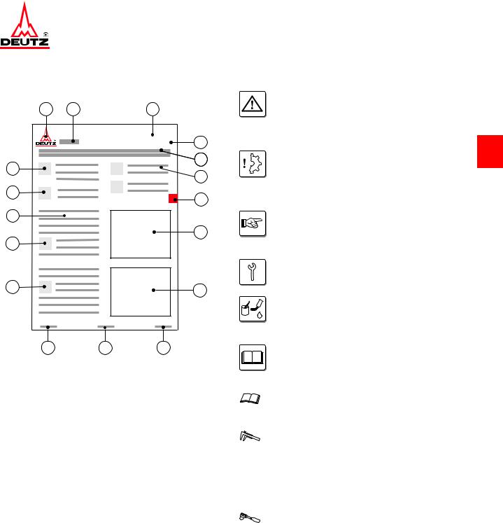
3.4.2 Structure of a job card
5
16
6
15
6 7
14
8
13
1.DEUTZ AG,
publisher of service documentation
2.Engine type (e.g. TCD 2013 4V)
3.Maintenance group
4.Job card number or topic
5.Title of job card
6.Reference to other job cards
7.Chapter
8.Graphic or photo
9.DEUTZ internal creation number 10.Page number
11.Date of issue of job card 12.Note
13.Danger / Important 14.Work sequence
15.Special tools; auxiliary materials 16.Conventional tools
3.5 Explanation of symbols
|
Danger! |
|
|
of death or to health. Must be observed! |
|
|
For example: The incorrect use or conver- |
|
|
sion of the turbocharger can lead to serious |
|
|
injury. |
3 |
|
Caution! |
Danger to the component/engine. Noncompliance can lead to destruction of the component/engine.
Must be observed!
Note
General notes on assembly, environmental protection etc. No potential danger for man or machine.
Tool
Conventional and special tools required for the work.
Auxiliary materials
Working materials required in addition to the tools for performing the work
(e.g. greases, oils, adhesives, sealants)
References
to important documents or job cards for the work process.
For example: Job card W 04-05-05
Reference
to a document or a job card within the work process.
Test and setting data
The necessary values are specified here. If several values are necessary, a cross reference is given to the Test and Setting Values table.
For example:
ID no. P01 61 = valve clearance, inlet
Tightening specification
The necessary values are specified here. If several values are necessary, a cross reference is given to the Tightening Specifications table.
For example:
ID no. A01 001 = cylinder head screws

3
![]()
|
D 2011 |
Job card overview |
|
TD 2011 |
Sorted alphabetically |
5
5Job card overview
5.1Sorted alphabetically
|
© 01/2009 |
1/8 |
OBJ_DOKU-24383-001.fm |

|
Job card overview |
D 2011 |
|
Sorted alphabetically |
TD 2011 |
5
|
© 01/2009 |
2/8 |
OBJ_DOKU-24383-001.fm |

|
D 2011 |
Job card overview |
||||
|
TD 2011 |
Sorted alphabetically |
||||
|
Activity |
Job card |
Maintenance group |
|||
|
Calculating the thickness of shim |
W 07-06-03 |
Fuel system |
|||
|
Check start of injection |
W 07-06-01 |
Fuel system |
|||
|
Checking the compression pressure |
W 00-02-06 |
General |
|||
|
Dismantling and assembling the cooling blower |
W 09-11-02 |
Cooling system |
|||
|
Installing and removing charge air pressure-de— |
W 07-08-02 |
Fuel system |
|||
|
pendent full load stop |
|||||
|
Mounting engine on assembly block and demoun— |
W 00-05-01 |
General |
|||
|
5 |
|||||
|
ting |
|||||
|
Remove and install the cooling blower |
W 09-11-01 |
Cooling system |
|||
|
Removing and install the charge air line |
W 06-02-03 |
Exhaust system/Charging |
|||
|
Removing and installing air duct |
W 09-11-03 |
Cooling system |
|||
|
Removing and installing fuel pipes |
W 07-10-06 |
Fuel system |
|||
|
Removing and installing rear cover |
W 03-09-01 |
Crankcase |
|||
|
Removing and installing temperature transmitter |
W 08-11-11 |
Lube oil system |
|||
|
Removing and installing the air bearing |
W 09-13-02 |
Cooling system |
|||
|
Removing and installing the connection housing |
W 03-09-04 |
Crankcase |
|||
|
Removing and installing the control line |
W 08-16-01 |
Lube oil system |
|||
|
Removing and installing the crankcase bleeding |
W 03-01-11 |
Crankcase |
|||
|
Removing and installing the exhaust damper |
W 06-01-05 |
Exhaust system/Charging |
|||
|
Removing and installing the exhaust gas collection |
W 06-09-08 |
Exhaust system/Charging |
|||
|
pipe (Exhaust gas recirculation) |
|||||
|
Removing and installing the exhaust gas return pipe |
W 06-09-07 |
Exhaust system/Charging |
|||
|
Removing and installing the exhaust gas return val— |
W 06-09-06 |
Exhaust system/Charging |
|||
|
ve |
|||||
|
Removing and installing the exhaust line |
W 06-01-05 |
Exhaust system/Charging |
|||
|
Removing and installing the flywheel |
W 12-06-01 |
Other components |
|||
|
Removing and installing the fuel filter console |
W 07-10-08 |
Fuel system |
|||
|
Removing and installing the fuel filter console |
W 07-10-08 |
Fuel system |
|||
|
Removing and installing the fuel injector pump |
W 07-04-01 |
Fuel system |
|||
|
Removing and installing the fuel injectors |
W 07-07-01 |
Fuel system |
|||
|
Removing and installing the fuel supply pump |
W 07-11-01 |
Fuel system |
|||
|
Removing and installing the generator |
W 13-02-03 |
Electrical system |
|||
|
Removing and installing the glow plug |
W 13-06-02 |
Electrical system |
|||
|
Removing and installing the heating plugs |
W 13-06-01 |
Electrical system |
|||
|
Removing and installing the hydraulic pump |
W 12-08-02 |
Other components |
|||
|
Removing and installing the impulse transmitter |
W 05-07-01 |
Speed control |
|||
|
Removing and installing the intake manifold |
W 06-07-03 |
Exhaust system/Charging |
|||
|
© 01/2009 |
3/8 |
OBJ_DOKU-24383-001.fm |

|
Job card overview |
D 2011 |
|||||
|
Sorted alphabetically |
TD 2011 |
|||||
|
Activity |
Job card |
Maintenance group |
||||
|
Removing and installing the lifting magnet (charge |
W 07-08-01 |
Fuel system |
||||
|
air pressure-dependent full load stop) |
||||||
|
Removing and installing the lifting magnet (Engine |
W 11-00-03 |
Monitoring system |
||||
|
shutdown) |
||||||
|
Removing and installing the lifting magnet (Start |
W 07-02-07 |
Fuel system |
||||
|
amount release) |
||||||
|
Removing and installing the lubricating oil cooler |
W 08-08-02 |
Lube oil system |
||||
|
Removing and installing the lubricating oil pan |
W 08-04-07 |
Lube oil system |
||||
|
5 |
||||||
|
(metal sheet lubricating oil pan) |
||||||
|
Removing and installing the lubricating oil pump |
W 08-04-05 |
Lube oil system |
||||
|
Removing and installing the magnet clip (Exhaust |
W 06-09-10 |
Exhaust system/Charging |
||||
|
gas recirculation) |
||||||
|
Removing and installing the oil filter console |
W 08-11-07 |
Lube oil system |
||||
|
Removing and installing the oil pressure regulating |
W 08-11-02 |
Lube oil system |
||||
|
valve |
||||||
|
Removing and installing the oil pressure switch |
W 08-11-08 |
Lube oil system |
||||
|
Removing and installing the oil suction pipe |
W 08-04-06 |
Lube oil system |
||||
|
Removing and installing the rocker arm and rocker |
W 01-02-02 |
Cylinder head |
||||
|
arm bracket |
||||||
|
Removing and installing the sensor (Exhaust gas |
W 06-09-09 |
Exhaust system/Charging |
||||
|
recirculation) |
||||||
|
Removing and installing the starter |
W 13-03-02 |
Electrical system |
||||
|
Removing and installing the starter |
W 13-03-02 |
Electrical system |
||||
|
Removing and installing the thermostat (Lubricating |
W 08-11-12 |
Lube oil system |
||||
|
oil cooler) |
||||||
|
Removing and installing the toothed belt wheel |
W 04-04-15 |
Engine control |
||||
|
Removing and installing the turbocharger |
W 06-06-04 |
Exhaust system/Charging |
||||
|
Removing and installing the V-belt pulley |
W 12-01-04 |
Other components |
||||
|
Renew camshaft sealing ring (opposite side to fly— |
W 04-03-01 |
Engine control |
||||
|
wheel) |
||||||
|
Renew toothed belt and tensioning pulley |
W 04-04-12 |
Engine control |
||||
|
Renewtoothedbeltandtensioningpulley(Hydraulic |
W 12-08-03 |
Other components |
||||
|
pump) |
||||||
|
Renew V-belts, check V-belt tension |
W 12-02-01 |
Other components |
||||
|
Renewing the crankshaft sealing ring (flywheel side) |
W 02-02-02 |
Drive system |
||||
|
Renewing the crankshaft sealing ring (opposite side |
W 02-02-04 |
Drive system |
||||
|
to flywheel) |
||||||
|
Renewing the injection lines |
W 07-03-01 |
Fuel system |
||||
|
Setting valve clearance |
W 01-01-01 |
Cylinder head |
||||
|
Steuerzeiten prüfen |
W 04-04-11 |
Engine control |
||||
|
© 01/2009 |
4/8 |
OBJ_DOKU-24383-001.fm |

|
D 2011 |
Job card overview |
|
TD 2011 |
Sorted numerically |
5
5.2Sorted numerically
|
© 01/2009 |
5/8 |
OBJ_DOKU-24383-001.fm |

|
Job card overview |
D 2011 |
|
Sorted numerically |
TD 2011 |
5
|
© 01/2009 |
6/8 |
OBJ_DOKU-24383-001.fm |

|
D 2011 |
Job card overview |
||||||
|
TD 2011 |
Sorted numerically |
||||||
|
Job card |
Activity |
Maintenance group |
|||||
|
W 00-02-06 |
Checking the compression pressure |
General |
|||||
|
W 00-05-01 |
Mounting engine on assembly block and demoun— |
General |
|||||
|
ting |
|||||||
|
W 01-01-01 |
Setting valve clearance |
Cylinder head |
|||||
|
W 01-02-02 |
Removing and installing the rocker arm and rocker |
Cylinder head |
|||||
|
arm bracket |
|||||||
|
W 02-02-02 |
Renewing the crankshaft sealing ring (flywheel side) |
Drive system |
|||||
|
5 |
|||||||
|
W 02-02-04 |
Renewing the crankshaft sealingring (opposite side |
Drive system |
|||||
|
to flywheel) |
|||||||
|
W 03-01-11 |
Removing and installing the crankcase bleeding |
Crankcase |
|||||
|
W 03-09-01 |
Removing and installing rear cover |
Crankcase |
|||||
|
W 03-09-04 |
Removing and installing the connection housing |
Crankcase |
|||||
|
W 04-03-01 |
Renew camshaft sealing ring (opposite side to fly— |
Engine control |
|||||
|
wheel) |
|||||||
|
W 04-04-11 |
Steuerzeiten prüfen |
Engine control |
|||||
|
W 04-04-12 |
Renew toothed belt and tensioning pulley |
Engine control |
|||||
|
W 04-04-15 |
Removing and installing the toothed belt wheel |
Engine control |
|||||
|
W 05-07-01 |
Removing and installing the impulse transmitter |
Speed control |
|||||
|
W 06-01-05 |
Removing and installing the exhaust line |
Exhaust system/Charging |
|||||
|
W 06-01-05 |
Removing and installing the exhaust damper |
Exhaust system/Charging |
|||||
|
W 06-02-03 |
Removing and install the charge air line |
Exhaust system/Charging |
|||||
|
W 06-06-04 |
Removing and installing the turbocharger |
Exhaust system/Charging |
|||||
|
W 06-07-03 |
Removing and installing the intake manifold |
Exhaust system/Charging |
|||||
|
W 06-09-06 |
Removing and installing the exhaust gas return val— |
Exhaust system/Charging |
|||||
|
ve |
|||||||
|
W 06-09-07 |
Removing and installing the exhaust gas return pipe |
Exhaust system/Charging |
|||||
|
W 06-09-08 |
Removing and installing the exhaust gas collection |
Exhaust system/Charging |
|||||
|
pipe (Exhaust gas recirculation) |
|||||||
|
W 06-09-09 |
Removing and installing the sensor (Exhaust gas |
Exhaust system/Charging |
|||||
|
recirculation) |
|||||||
|
W 06-09-10 |
Removing and installing the magnet clip (Exhaust |
Exhaust system/Charging |
|||||
|
gas recirculation) |
|||||||
|
W 07-02-07 |
Removing and installing the lifting magnet (Start |
Fuel system |
|||||
|
amount release) |
|||||||
|
W 07-03-01 |
Renewing the injection lines |
Fuel system |
|||||
|
W 07-04-01 |
Removing and installing the fuel injector pump |
Fuel system |
|||||
|
W 07-06-01 |
Check start of injection |
Fuel system |
|||||
|
W 07-06-03 |
Calculating the thickness of shim |
Fuel system |
|||||
|
W 07-07-01 |
Removing and installing the fuel injectors |
Fuel system |
|||||
|
© 01/2009 |
7/8 |
OBJ_DOKU-24383-001.fm |

|
Job card overview |
D 2011 |
|||||
|
Sorted numerically |
TD 2011 |
|||||
|
Job card |
Activity |
Maintenance group |
||||
|
W 07-08-01 |
Removing and installing the lifting magnet (charge |
Fuel system |
||||
|
air pressure-dependent full load stop) |
||||||
|
W 07-08-02 |
Installing and removing charge air pressure-de— |
Fuel system |
||||
|
pendent full load stop |
||||||
|
W 07-10-06 |
Removing and installing fuel pipes |
Fuel system |
||||
|
W 07-10-08 |
Removing and installing the fuel filter console |
Fuel system |
||||
|
W 07-10-08 |
Removing and installing the fuel filter console |
Fuel system |
||||
|
5 |
W 07-11-01 |
Removing and installing the fuel supply pump |
Fuel system |
|||
|
W 08-04-05 |
Removing and installing the lubricating oil pump |
Lube oil system |
||||
|
W 08-04-06 |
Removing and installing the oil suction pipe |
Lube oil system |
||||
|
W 08-04-07 |
Removing and installing the lubricating oil pan |
Lube oil system |
||||
|
(metal sheet lubricating oil pan) |
||||||
|
W 08-08-02 |
Removing and installing the lubricating oil cooler |
Lube oil system |
||||
|
W 08-11-02 |
Removing and installing the oil pressure regulating |
Lube oil system |
||||
|
valve |
||||||
|
W 08-11-07 |
Removing and installing the oil filter console |
Lube oil system |
||||
|
W 08-11-08 |
Removing and installing the oil pressure switch |
Lube oil system |
||||
|
W 08-11-11 |
Removing and installing temperature transmitter |
Lube oil system |
||||
|
W 08-11-12 |
Removing and installing the thermostat (Lubricating |
Lube oil system |
||||
|
oil cooler) |
||||||
|
W 08-16-01 |
Removing and installing the control line |
Lube oil system |
||||
|
W 09-11-01 |
Remove and install the cooling blower |
Cooling system |
||||
|
W 09-11-02 |
Dismantling and assembling the cooling blower |
Cooling system |
||||
|
W 09-11-03 |
Removing and installing air duct |
Cooling system |
||||
|
W 09-13-02 |
Removing and installing the air bearing |
Cooling system |
||||
|
W 11-00-03 |
Removing and installing the lifting magnet (Engine |
Monitoring system |
||||
|
shutdown) |
||||||
|
W 12-01-04 |
Removing and installing the V-belt pulley |
Other components |
||||
|
W 12-02-01 |
Renew V-belts, check V-belt tension |
Other components |
||||
|
W 12-06-01 |
Removing and installing the flywheel |
Other components |
||||
|
W 12-08-02 |
Removing and installing the hydraulic pump |
Other components |
||||
|
W 12-08-03 |
Renewtoothedbeltandtensioningpulley(Hydraulic |
Other components |
||||
|
pump) |
||||||
|
W 13-02-03 |
Removing and installing the generator |
Electrical system |
||||
|
W 13-03-02 |
Removing and installing the starter |
Electrical system |
||||
|
W 13-03-02 |
Removing and installing the starter |
Electrical system |
||||
|
W 13-06-01 |
Removing and installing the heating plugs |
Electrical system |
||||
|
W 13-06-02 |
Removing and installing the glow plug |
Electrical system |
||||
|
© 01/2009 |
8/8 |
OBJ_DOKU-24383-001.fm |

|
6 |
Job cards |
||
|
6 |
|||
|
© 11/2005 |
1/2 |
OBJ_DOKU-23455-001.fm |

6
|
© 11/2005 |
2/2 |
OBJ_DOKU-23455-001.fm |
![]()
|
D 2011 |
General |
||||||
|
TD 2011 |
W 00-02-06 |
||||||
Checking the compression pressure |
|||||||
|
Standard tools: |
– W 01-01-01 |
||||||
|
– Compression pressure |
– W 07-07-01 |
||||||
|
tester |
8005 |
||||||
|
Special tools: |
Attention! |
||||||
|
– Connector |
100120 |
Pay attention to utmost cleanliness when |
|||||
|
working on the fuel system. |
|||||||
|
Remove residue paint and particles of dirt |
|||||||
|
before removing. |
|||||||
|
Clean the respective affected parts |
|||||||
|
carefully. Blow damp areas dry with com— |
|||||||
|
pressed air. |
|||||||
|
Observe the safety regulations and natio— |
|||||||
|
nal specifications for handling fuels. |
6 |
||||||
|
Close all connections immediately after |
opening with new, clean plugs/caps. Do not remove plugs/caps until immedia— tely before assembling.
Collect leaking operating substances in suitable vessels and dispose of according to regulations.
After all work on the fuel system, it must be bleeded — see the operation manual, chap— ter «6 Fuel system“.
Checking the compression pressure
●Set valve clearance.
W 01-01-01 ●Removing fuel injectors.
W 07-07-01
●Mount sealing ring (1).
 Use sealing ring (1) for fuel injector. ●Insert connector (2).
© 47001-1
|
© 01/2009 |
1/6 |
OBJ_DOKU-23456-001.fm |

|
General |
D 2011 |
|
W 00-02-06 |
TD 2011 |
●Mount clamping shoe (1). ●Tighten screw (2).
21 Nm
6
© 47002-0
●Connect adapter (1) to connector.
© 47004-0
●Mount the compression tester on the adapter. ●Turn over engine with starter.
25 — 30 bar (2500 — 3000 kPa)
© 46308-0
|
© 01/2009 |
2/6 |
OBJ_DOKU-23456-001.fm |

|
D 2011 |
General |
|
TD 2011 |
W 00-02-06 |
The measured compression pressure depends on the starting speed during the measuring process and the altitude of the engine installation site. Therefore, limit values cannot be determined exactly. The compression pressure measurement is only recommended as a reference measu— rement of all cylinders of an engine to each other. If more than 15% deviation has been determined, the cause should be deter— mined by disassembling the cylinder unit concerned.
No.
Kompression in bar
Compression value in bar
|
Pression |
en bar Dat. _________ |
|||||||||
|
10 |
15 |
20 |
25 |
30 |
35 |
40 |
||||
|
Zyl. |
||||||||||
1
2
3
4
5
6
7
8
|
DBGM |
Made in Germany |
6 |
|
|
MOTOMETER |
|||
|
© 45103-0 |
●Remove the compression pressure tester.
© 47003-0
●Remove the compression pressure tester and adapter (1).
© 47004-0
|
© 01/2009 |
3/6 |
OBJ_DOKU-23456-001.fm |

General
W 00-02-06
●Unscrew screw (1).
6
●Remove connector (1). ●Remove sealing ring. ●Install fuel injectors.
W 07-07-01
D 2011
TD 2011
© 47005-0
© 47001-0
|
© 01/2009 |
4/6 |
OBJ_DOKU-23456-001.fm |

|
D 2011 |
General |
||||||
|
TD 2011 |
W 00-02-06 |
||||||
|
Technical Data |
|||||||
|
Testing and setting data |
|||||||
|
ID no. |
Name |
Additional information |
Value |
||||
|
P00 51 |
Compression pressure |
25 — 30 bar |
|||||
|
(2500 — 3000 kPa) |
|||||||
|
Tightening specifications |
|||||||
|
ID no. |
Name |
Screw type |
Notes / Remark |
Value |
|||
|
A07 001 |
Fuel injector on cylinder head |
21 Nm |
|
For the tightening procedure according to torque using a torque wrench, a maximum variation of the |
|
|
tightening torque of +/- 10% is permissible. |
6 |
|
© 01/2009 |
5/6 |
OBJ_DOKU-23456-001.fm |

|
General |
D 2011 |
|
W 00-02-06 |
TD 2011 |
6
|
© 01/2009 |
6/6 |
OBJ_DOKU-23456-001.fm |

|
D 2011 |
General |
|
TD 2011 |
W 00-05-01 |
Mounting engine on assembly block and demounting
Standard tools:
– Lifting gear
– Suspension ropes
– Eyelet bolts
|
Special tools: |
|
|
– Assembly block |
6067 |
|
– Supporting bracket |
6067/114 |
|
– Clamping bracket |
6067/115 |
 – W 13-03-02
Danger!
When using hoists (workshop crane) the safety regulations for handling hoists must be observed.
It is not permitted to stay under moving loads.
Different customer scopes are not taken into account in the repair sequence shown
here, accessories which deviate from the 6 standard equipment are not shown.
|
Mounting engine on assembly block |
||
|
●Remove starter. |
1 |
|
|
W 13-03-02 |
||
|
●Screw in eyelet bolts (1). |
© 47006-0
●Hang engine on workshop crane.
– D 2011 L02
approx. 169 — 175 kg
– D 2011 L03
approx. 210 -217 kg
– D 2011 L04
approx. 253 — 261 kg
– TD 2011 L04
approx. 255 — 258 kg
© 47007-0
|
© 01/2009 |
1/6 |
OBJ_DOKU-23457-001.fm |

|
General |
D 2011 |
|
W 00-05-01 |
TD 2011 |
●Unscrew screws (1). ●Remove all mounting feet.
– TD 2011 ●Unscrew screw (2). ●Remove holder (3).
●Remove oil return pipe (4).
6
●Mount clamping holder (1). ●Tighten screws (2).
90 Nm
●Align engine on engine block. ●Mount retainer plate (1). ●Tighten screws (2) and lock nuts.
90 Nm
|
© 01/2009 |
2/6 |
OBJ_DOKU-23457-001.fm |

|
D 2011 |
General |
|
TD 2011 |
W 00-05-01 |
●Unhook engine. ●Unscrew eyelet bolts (1).
6
© 47006-0
|
Demounting engine from assembly block |
||
|
●Screw in eyelet bolts (1). |
1 |
|
|
●Hang engine on workshop crane. |
||
|
– D 2011 L02 |
approx. 169 — 175 kg
– D 2011 L03
approx. 210 -217 kg
– D 2011 L04
approx. 253 — 261 kg
– TD 2011 L04
approx. 255 — 258 kg
© 47006-0
●Loosen lock nuts. ●Unscrew screws (2). ●Remove retainer plate (1).
1
© 47010-0
|
© 01/2009 |
3/6 |
OBJ_DOKU-23457-001.fm |

|
General |
D 2011 |
|
W 00-05-01 |
TD 2011 |
Danger!
Lower engine with workshop crane.
●Unscrew screws (2). ●Remove clamping bracket (1).
6
– TD 2011
●Insert new O-ring (1). ●Lightly oil new O-ring (1).
– TD 2011
●Mount oil return pipe (1).
Attention!
Install tension-free.
●Mount holder (2). ●Tighten screw (3).
8.5 Nm
– D 2011, TD 2011 ●Install all mounting feet. ●Tighten screws (4).
200 Nm
|
© 01/2009 |
4/6 |
OBJ_DOKU-23457-001.fm |
![]()
|
D 2011 |
General |
|
TD 2011 |
W 00-05-01 |
|
Danger! |
|
|
Put the engine down on a secure surface. |
|
|
●Unhook the engine from the workshop crane. |
1 |
|
●Unscrew eyelet bolts (1). |
|
|
●Install starter. |
|
|
W 13-03-02 |
6
© 47006-0
|
© 01/2009 |
5/6 |
OBJ_DOKU-23457-001.fm |

|
General |
D 2011 |
|||||||||||
|
W 00-05-01 |
TD 2011 |
|||||||||||
|
Technical Data |
||||||||||||
|
Testing and setting data |
||||||||||||
|
ID no. |
Name |
Additional information |
Value |
|||||||||
|
D 2011 L02 |
||||||||||||
|
P00 |
04 |
Engine weight according to DIN 70020-A |
approx. 169 — |
|||||||||
|
175 kg |
||||||||||||
|
D 2011 L03 |
||||||||||||
|
P00 |
04 |
Engine weight according to DIN 70020-A |
approx. 210 — |
|||||||||
|
217 kg |
||||||||||||
|
D 2011 L04 |
||||||||||||
|
P00 |
04 |
Engine weight according to DIN 70020-A |
approx. 253 — |
|||||||||
|
261 kg |
||||||||||||
|
6 |
TD 2011 |
L04 |
||||||||||
|
P00 |
04 |
Engine weight according to DIN 70020-A |
approx. 255 — |
|||||||||
|
258 kg |
||||||||||||
|
Tightening specifications |
||||||||||||
|
ID no. |
Name |
Screw type |
Notes / Remark |
Value |
||||||||
|
A00 |
001 |
Clamping bracket on crankcase |
90 Nm |
|||||||||
|
A00 |
002 |
Clamping bracket on adapter for |
90 Nm |
|||||||||
|
assembly block |
||||||||||||
|
A00 |
003 |
Mounting foot/engine mounting on |
M14x55-12.9 |
200 Nm |
||||||||
|
crankcase |
M14x100-12.9 |
|||||||||||
|
TD 2011 |
||||||||||||
|
A08 |
049 |
Holder oil return line on crankcase |
Torx, |
8.5 Nm |
||||||||
|
M6x14-8.8 |
||||||||||||
For the tightening procedure according to torque using a torque wrench, a maximum variation of the tightening torque of +/- 10% is permissible.
|
© 01/2009 |
6/6 |
OBJ_DOKU-23457-001.fm |

|
D 2011 |
Cylinder head |
|
TD 2011 |
W 01-01-01 |
Setting valve clearance
Standard tools:
– Feeler gauges
●Unscrew all screws (1). ●Remove cylinder head cowling (2). ●Remove gasket.
Attention!
In case of internal exhaust gas recircula— tion, the inlet valve is opened briefly by an additional cam on the camshaft.
This is not to be confused with the valve overlap.
Allow the engine to cool down for at least 30 minutes before setting the valve
clearance. Engine oil temperature < 80 °C
The following work procedure describes the setting of the valve clearance on an inlet valve. The procedure is the same for
the setting on an outlet valve, taking into 6 consideration the setting dimension.
2
© 39131-5
Setting engine to valve overlap
●Turn crankshaft inthedirection of the engine (arrow).
●Turn over crankshaft until the valve overlap is achieved on cylinder 1.
© 39132-2
|
© 01/2009 |
1/6 |
OBJ_DOKU-23458-001.fm |

|
Cylinder head |
D 2011 |
|
W 01-01-01 |
TD 2011 |
Arrangement of the inlet and exhaust val— ves.
IN = inlet valve EX = exhaust valve
Valve overlap means:
The inlet valve starts opening,exhaust valve closes.
Attention!
In case of internal exhaust gas recircula— tion, the inlet valve is opened briefly by an additional cam on the camshaft.
This is not to be confused with the valve overlap.
6
●Select feeler gauge.
●Check the setting on the appropriate valve.
The feeler gauge must pass between the rocker arm’s sliding surface and the valve without too much resistance.
© 39135-1
Setting valve clearance
●Loosen lock nut (1). ●Hold adjusting screw (2). ●Set valve clearance.
|
If there is not enough valve clearance, |
|
|
unscrew setting screw (2). |
2 |
|
If there is too much valve clearance, turn in |
|
|
setting screw (2). |
|
|
– Inlet |
|
|
0.3 mm |
|
|
– Outlet |
1 |
|
0.5 mm |
|
|
© 39136-1 |
|
© 01/2009 |
2/6 |
OBJ_DOKU-23458-001.fm |

|
D 2011 |
Cylinder head |
|
TD 2011 |
W 01-01-01 |
●Check the valve clearance with feeler gauge (1).
6
© 39135-2
●Hold adjusting screw (2). ●Tighten lock nut (1).
20 Nm
Do not turn the setting screw when tigh— tening the locking nut.
© 39136-1
●Check the valve clearance again with feeler gauge.
© 39135-1
|
© 01/2009 |
3/6 |
OBJ_DOKU-23458-001.fm |

|
Cylinder head |
D 2011 |
|
|
W 01-01-01 |
TD 2011 |
|
|
Valve clearance setting schematic |
||
|
– D 2011 |
||
|
According to the order given below, the |
||
|
setting of the valve clearance is possible in |
||
|
two turns of the crankshaft (each 360°). |
||
|
Crankshaft position 1 |
||
|
●Turn over crankshaft until the valve overlap is |
||
|
achieved on cylinder 1. |
||
|
●Set black marked valves. |
||
|
6 |
Crankshaft position 2 |
|
|
●Turn the crankshaft one turn (360°). |
© 25894-5 |
|
|
●Set black marked valves. |
|
– TD 2011 |
||||||
|
Valves |
Cylinders |
|||||
|
overlap |
1 |
3 |
4 |
2 |
||
|
set to |
4 |
2 |
1 |
3 |
Valve overlap: Outlet valve is not yet closed, inlet valve begins to open.
When the outlet valve is fully open, the inlet valve opens briefly approx. 2 mm. This is not the valve overlap!
|
●Clean sealing surfaces. |
|
|
●Mount new gasket. |
|
|
Note installation position: The bar (1) must |
1 |
|
face the front cover. |
© 47500-0
|
© 01/2009 |
4/6 |
OBJ_DOKU-23458-001.fm |

|
D 2011 |
Cylinder head |
|
TD 2011 |
W 01-01-01 |
|
●Mount cylinder head cover. |
|
|
●Oil the screws lightly. |
|
|
●Tighten all screws (1) alternately. |
|
|
8.5 Nm |
1 |
6
© 39131-4
|
© 01/2009 |
5/6 |
OBJ_DOKU-23458-001.fm |

|
Cylinder head |
D 2011 |
|||||
|
W 01-01-01 |
TD 2011 |
|||||
|
Technical Data |
||||||
|
Testing and setting data |
||||||
|
ID no. |
Name |
Additional information |
Value |
|||
|
D 2011 L02 |
||||||
|
P00 71 |
Ignition sequence |
1-2 |
||||
|
D 2011 L03 |
||||||
|
P00 71 |
Ignition sequence |
1-2-3 |
||||
|
D 2011 L04 |
||||||
|
P00 71 |
Ignition sequence |
1-3-4-2 |
||||
|
D 2011, |
TD 2011 |
|||||
|
P01 61 |
Valve clearance (inlet) |
0.3 mm |
||||
|
P01 62 |
Valve clearance (outlet) |
0.5 mm |
6Tightening specifications
|
ID no. |
Name |
Screw type Notes / Remark |
Value |
|
A01 003 |
Locking nut, valve adjuster |
20 Nm |
|
|
A01 004 |
Cylinder head cover on cylinder head |
8.5 Nm |
For the tightening procedure according to torque using a torque wrench, a maximum variation of the tightening torque of +/- 10% is permissible.
|
© 01/2009 |
6/6 |
OBJ_DOKU-23458-001.fm |

|
D 2011 |
Cylinder head |
|||||
|
TD 2011 |
W 01-02-02 |
|||||
Removing and installing the rocker arm and rocker arm bracket |
||||||
|
Standard tools: |
– W 01-01-01 |
|||||
|
– Torx tool set |
8189 |
6
Removing the rocker arm and rocker arm bracket
|
●Unscrew all screws (1). |
1 |
|
|
●Remove cylinder head cowling (2). |
||
|
●Remove gasket. |
||
|
2 |
© 39131-5
●Unscrew screws (1).
Loosen screws evenly to avoid tension on the rocker arm brackets.
|
●Remove rocker arm bracket (2). |
1 |
|
Lay out components in the order in which |
|
|
they should be installed. |
|
|
Note order of cylinders. |
© 39140-1
|
© 01/2009 |
1/4 |
OBJ_DOKU-23459-001.fm |

|
Cylinder head |
D 2011 |
|
W 01-02-02 |
TD 2011 |
●Remove push rods (1).
Lay out components in the order in which they should be installed.
●Visually inspect the components.
6
Installing the rocker arm and rocker arm bracket
●Insert stop rods (1).
Note the assignment of the stop rods.
The stop rod must be seated with the ball head in the ladle of the tappet.
© 39141-1
●Loosen lock nut (1).
|
●Unscrew setting screws (2). |
|
|
●Mount rocker arm bracket (3). |
3 |
|
●Position rocker arm. |
The ball heads (4) must be seated in the ladles of the stop rods.
The rocker arm (arrow) must sit on the valve stem.
|
© 01/2009 |
2/4 |
OBJ_DOKU-23459-001.fm |
 Loading…
Deutz Engines 912, BF4M2012, F4M2011, BF4M2011, 1011F operators, service and maintenance manuals, error codes list, DTC, spare parts manuals & catalogues, wiring diagrams, schematics free download PDF
![]()
Deutz logo
Deutz engine manuals free download are available for free download.
| Title | File Size | Download Links |
| Deutz 2008-2009 Parts Manual [PDF] | 3.1Mb | Download |
| Deutz 2008-2009 Service Manual [PDF] | 4.4Mb | Download |
| Deutz 226B Operation Manual [PDF] | 8.5Mb | Download |
| Deutz 413 Parts Manual [PDF] | 4.5Mb | Download |
| Deutz Accessories Catalogue [PDF] | 5.2Mb | Download |
| Deutz BF4M1013C Spare Parts Catalogue [PDF] | 3Mb | Download |
| Deutz BFM 1015 Series – BF6M 1015 C, BF8M 1015, BF8M 1015 C, BF8M 1015 CP, BF6M 1015 CP Workshop Manual [PDF] | 12.3Mb | Download |
| Deutz D 2008-2009 Workshop Manual [PDF] | 4.6Mb | Download |
| Deutz D 909 / 910, B / FL 1011 / F / 2011, B / FL 912 / 913 / 914 / C, B / FL 413 F / 513 / C / CP, B / FM 1011 F 2011 Installation Manual [PDF] | 7.8Mb | Download |
| Deutz Engine D2008 2009 Workshop Manual PDF [PDF] | 3.8Mb | Download |
| Deutz Engine Fire Protection – Operation Manual [PDF] | 21.2Mb | Download |
| Deutz Engine S-BV6-8-9M628 Operation Manual [PDF] | 10Mb | Download |
| Deutz FL 411 Service Manual [PDF] | 8.7Mb | Download |
| Deutz FL 413 Service Manual [PDF] | 8.7Mb | Download |
| Deutz Serie 7 Agrotron Service Manual [PDF] | 4.1Mb | Download |
| Gt-50dz Tow Tractor With Deutz Engine [PDF] | 36.1Mb | Download |
Deutz 912
| Title | File Size | Download Links |
| Deutz 912 Parts Manual [PDF] | 4.3Mb | Download |
| Deutz 912 Technical Specifications [PDF] | 384.6kb | Download |
| Deutz 912-913 Repair Manual [PDF] | 5.8Mb | Download |
| Deutz 912-913 Service Manual [PDF] | 2.6Mb | Download |
| Deutz 912-913 Workshop Manual [PDF] | 34.5Mb | Download |
| Deutz F 3 L912 / W, F 4 L912 / W, F 5 L912 / W, B / F6 L912 / W Spare Parts Catalog [PDF] | 15.7Mb | Download |
Deutz 914
| Title | File Size | Download Links |
| Deutz 914 Parts Manual [PDF] | 4.3Mb | Download |
| Deutz 914 Service Manual [PDF] | 2.7Mb | Download |
| Deutz Engine 914 Operation Manual [PDF] | 3.2Mb | Download |
Deutz 1008
| Title | File Size | Download Links |
| Deutz – Workshop Manual BFM 1008F part 1 [PDF] | 2.5Mb | Download |
| Deutz – Workshop Manual BFM 1008F part 2 [PDF] | 2.2Mb | Download |
| Deutz Engines B / FM 1008 / F Workshop Manual [PDF] | 2.7Mb | Download |
Deutz 1011
| Title | File Size | Download Links |
| Deutz 0312 1936 2011 Workshop Manual [PDF] | 20.6Mb | Download |
| Deutz 1011 Parts Manual [PDF] | 1.9Mb | Download |
| Deutz 1011F Workshop Manual [PDF] | 4.7Mb | Download |
| Deutz BF4m1011F Engine Service Parts Manual [PDF] | 4.2Mb | Download |
| Deutz Engine 1011F Werkstatthandbuch [PDF] | 10.3Mb | Download |
| Deutz Engine 1011F Workshop Manual [PDF] | 10.6Mb | Download |
| Deutz Engine B-F L 1011F B-FM 1011F Operation Manual – Engine Description [PDF] | 1.1Mb | Download |
| Deutz Engine B-F L 1011F B-FM 1011F Operation Manual – Engine Operation [PDF] | 157.3kb | Download |
| Deutz Engine B-F L 1011F B-FM 1011F Operation Manual – Engine Preservation [PDF] | 14.2kb | Download |
| Deutz Engine B-F L 1011F B-FM 1011F Operation Manual – Faults, Causes and Remedies [PDF] | 25.1kb | Download |
| Deutz Engine B-F L 1011F B-FM 1011F Operation Manual – General [PDF] | 24.2kb | Download |
| Deutz Engine B-F L 1011F B-FM 1011F Operation Manual – Notes [PDF] | 144.3kb | Download |
| Deutz Engine B-F L 1011F B-FM 1011F Operation Manual – Operating Media [PDF] | 411.2kb | Download |
| Deutz Engine B-F L 1011F B-FM 1011F Operation Manual – Routine Maintenance [PDF] | 299.2kb | Download |
| Deutz Engine B-F L 1011F B-FM 1011F Operation Manual – Service and Maintenance [PDF] | 429.8kb | Download |
| Deutz Engine B-F L 1011F B-FM 1011F Operation Manual – Technical Specifications [PDF] | 53.8kb | Download |
| Deutz Engine B-FL 1011F Operation Manual [PDF] | 2.9Mb | Download |
| Deutz F3M 1011F, BF3M, F4M, BF4M Service Manual [PDF] | 1.3Mb | Download |
Deutz 1012 1013
| Title | File Size | Download Links |
| Deutz 1012 1013 Operation and Maintenance Manual [PDF] | 3.8Mb | Download |
| Deutz 1012-1013 Service Manual [PDF] | 3.6Mb | Download |
| Deutz Engine 1012-1013 Workshop Manual [PDF] | 4.7Mb | Download |
Deutz 1015
| Title | File Size | Download Links |
| Deutz 1015 Maintenance Manual rus [PDF] | 2.8Mb | Download |
| Deutz BFM 1015 Workshop Manual [PDF] | 3.9Mb | Download |
Deutz 2011
| Title | File Size | Download Links |
| Deutz 0312 1936 2011 Workshop Manual- competence level 3 [PDF] | 20.6Mb | Download |
| Deutz 0312 4004 2011 Workshop Manual- competence level 2 [PDF] | 7.5Mb | Download |
| Deutz 2011 – Operation Manual [PDF] | 2.7Mb | Download |
| Deutz D 2011 w, TD 2011 w, TCD 2011 w Workshop Manual- competence level 2 [PDF] | 9.9Mb | Download |
| Deutz D 2011, TD 2011 Workshop Manual- competence level 2 [PDF] | 15.8Mb | Download |
| Deutz Engine B-FL-FM 2011 Operation Manual [PDF] | 7.1Mb | Download |
| Deutz F2M 2011, F3M 2011, F4M 2011, BF3M 2011, BF4M 2011, BF3L 2011, BF4L 2011 F2L 2011, F3L 2011, F4L 2011 Operation Manual [PDF] | 5.2Mb | Download |
| Deutz F4M 2011 Technical Specifications [PDF] | 278.7kb | Download |
| Deutz F4M2011 Service Manual pdf [PDF] | 5.2Mb | Download |
Deutz 2012
| Title | File Size | Download Links |
| Deutz 2012 Service Manual [PDF] | 9.5Mb | Download |
| Deutz BF4M 2012 Operation Manual [PDF] | 4.6Mb | Download |
| Deutz BF4M2012 Workshop Manual [PDF] | 14.3Mb | Download |
| Deutz Engine 2012 Operation Manual [PDF] | 3.7Mb | Download |
| Deutz Engine BF6M 1013 Operation Manual [PDF] | 3.3Mb | Download |
| Deutz Engine BFM-2012 Workshop Manual [PDF] | 8.7Mb | Download |
Deutz TCD 2012
| Title | File Size | Download Links |
| Deutz TCD 2012-2013 Service Manual [PDF] | 3.9Mb | Download |
| Deutz TCD2012 Instruction Manual [PDF] | 5.1Mb | Download |
Deutz TCD 2013
| Title | File Size | Download Links |
| Deutz Engine TCD 2013 2V Workshop Manual [PDF] | 26.9Mb | Download |
| Deutz Engine TCD 2013 L04-06 4V Instruction Manual – Care and maintenance work [PDF] | 1017.5kb | Download |
| Engine corrosion protection [PDF] | 119kb | Download |
| Engine Description [PDF] | 2.1Mb | Download |
| Faults, causes, and remedies [PDF] | 79.7kb | Download |
| General [PDF] | 13.1kb | Download |
| Maintenance [PDF] | 493.5kb | Download |
| Operating substances [PDF] | 44.7kb | Download |
| Operation Manual [PDF] | 15.6kb | Download |
| Operation [PDF] | 151.7kb | Download |
| Service [PDF] | 22.5kb | Download |
| Technical data [PDF] | 72.2kb | Download |
| Deutz TCD 2013 4V – Industry Workshop Manual [PDF] | 535.7kb | Download |
Deutz Engine TCD 2015 Service Manual
| Title | File Size | Download Links |
| General [PDF] | 18.1kb | Download |
| Job card overview [PDF] | 20.3Mb | Download |
| Special tools [PDF] | 299.3kb | Download |
| Standard tools [PDF] | 93.2kb | Download |
| Technical data [PDF] | 185.4kb | Download |
| User notes [PDF] | 51.8kb | Download |
| Deutz TCD 2015 Service Manual [PDF] | 3.2Mb | Download |
Deutz Engines
Modern technologies and materials, top quality, dependability, durability, and longevity are all features of Deutz diesel engines manufactured in Germany. German brand engines have high specific power and torque at the lightest possible weight for power plants with such specs. As a result, Deutz engines, which use the company’s unique innovations, can function well even in the most adverse circumstances and at a high maximum load for extended periods without diminishing motor resources or increasing overhaul time, therefore saving operational expenses.
After years of research at the company’s scientific and design bureaus, Deutz engineers developed motors that balance low operating costs and little impact on the environment. Because of their low fuel consumption, power plants from the German company Deutz are among the most cost effective in the world per kilowatt-hour produced, and they conform to the strictest standards for environmental protection. This means you may save money on gasoline and put Deutz generator installations close to where people live and work.
The Deutz 413 Series consists of V-shaped (V-Twin) diesel engines with 6, 8, 10, or 12 cylinders, a horizontal selection shaft, and valves in the upper location (OHV) for use in industrial and domestic applications. Focused on usage in sub-zero temperatures (down to -30 degrees Celsius), the 137 hp. (100 kW) to 322 hp. (236 kW) range of power and forced air conditioning;
Four-stroke, overhead-valve (OHV), horizontal power-shaft (HPS), and forced-air-cooled (FAC.) Deutz 912 Series diesel engines are designed for typical circumstances and may produce anywhere from 47 horsepower (34 kilowatts) to 111 horsepower (70 kW) (82 kW). The W models have a two-stage fuel combustion mechanism;
The Deutz 913 Series consists of 4-stroke, 3, 4, and 6-cylinder diesel engines with OHV, a horizontal power shaft, and forced air cooling, designed for use in typical circumstances and ranging in output from 59 horsepower (44 kilowatts) to 191 horsepower (141 kilowatts);
The Deutz 914 Series consists of four-stroke, three-, four-, five-, and six-cylinder diesel engines designed for professional and household appliances, featuring overhead valves, a horizontal power shaft, and forced air cooling, and optimized for normal conditions of operation between 59 horsepower (44 kilowatts) and 189 horsepower (141 kilowatts);
The Deutz 912/914 Genset Series includes 19 hp (14 kW) to 97.9 hp (4-stroke, 2, 3, 4, 6, 6-cylinder, OHV, horizontal air-cooled shaft, air-cooled) diesel engines for electro generators designed for usage in normal and harsh climatic situations (73 kW) manufactured with a mechanical or electronic (optional) fuel supply regulator;
The Deutz 1008 Series is a line of four-stroke, 2, 3, and 4-cylinder diesel engines designed for use in construction machinery, featuring overhead valves (OHV), a horizontal power shaft, liquid cooling, and an emphasis on operating in harsh environments, with outputs ranging from 17.7 horsepower (13 kilowatts) to 42 horsepower (31 kilowatts).
The Deutz 1011 Series is a line of 30-liter, 4-stroke, 2-, 3-, and 4-cylinder diesel engines used in construction machinery. These engines have overhead valves (OHV), a horizontal power shaft, and liquid cooling and are optimized for usage in harsh climates. (22 kW) up to (89.5 hp) (61 kW). Gas emission regulations that are in line with those of the European Union’s STEP II and the United States CFR 40, part 89, Tier II;
The Deutz 1013 Series consists of 4-stroke, 4- and 6-cylinder diesel engines with OHV, the horizontal power shaft, liquid cooling, and an output range of 154 hp (115 kW) to 313 hp (233 kW) for use in industrial and construction equipment in both mild and severe climates.
The Deutz 1015 Series consists of 6- and 8-cylinder V-shaped diesel engines with OHV, a horizontal power shaft, liquid cooling, and an output range of 407 hp (300 kW) to 598 hp (440 kW) that are designed for usage in typical climates.
The Deutz 1013/1015 Genset Series consists of four-stroke, six- and eight-cylinder diesel engines for electric generators, with overhead valves (OHV), a horizontal power shaft, liquid cooling, and an output ranging from 103 horsepower (77 kilowatts) to 571 horsepower (362 kilowatts) (426 kW) produced using both a mechanical regulator and electronic control (as an extra);
With power ranging from 31 horsepower (23 kilowatts) to 88 horsepower (65 kilowatts), the Deutz 2011 Series consists of 2, 3, 4, and 4-cylinder diesel engines for mobile medium-power mobile equipment with OHV, horizontal power shaft, air or liquid cooling, and an emphasis on operation in normal climatic conditions; the L models feature a heat exchanger.
The Deutz TCD 2011 Series is a line of air-cooled, OHV, horizontally-mounted, 2- and 3-cylinder diesel engines for medium-power mobile equipment ranging in output from 31 to 100 horsepower (23 to 74 kilowatts) (74.9 kW). Meet the gas emission requirements of European Union (EU) STEP III and United States (US) Tier 3;

Deutz f4m2011
The Deutz 2012 Series is a line of four- and six-cylinder diesel engines designed for medium-power mobile equipment. They feature overhead valves (OHV), a horizontal power shaft, and liquid cooling and are optimized for use in typical climates. Their output ranges from 101.8 horsepower (74.9 kilowatts) to 210 horsepower (155 kilowatts).
The Deutz TCD 2012 Series is a four-stroke and six-cylinder diesel engine line designed for medium-power mobile equipment. They feature overhead valves (OHV), a horizontal power shaft, and liquid cooling and are optimized for use in temperate climates.
The Deutz 2011/2012 Genset Series consists of four-stroke 2, 3, and 4-cylinder diesel engines for electric generators with overhead valves, horizontal power shafts, liquid or air cooling, and a primary focus on operation in both normal and difficult climatic conditions, with outputs ranging from 15.5 horsepower (11.4 kilowatts) to 101 horsepower (75 kilowatts);
The Deutz TCD2013 Series is a line of four- and six-cylinder diesel engines designed for use in mobile medium-power equipment. These engines feature overhead valves (OHV), a horizontal power shaft, liquid cooling, and are optimized for use in temperate climates. Their output ranges from 173 horsepower (129 kilowatts) to 325.9 horsepower (243 kW). Meet the requirements for gas emissions set out by the European Union’s STEP III A and the United States’ Tier 3;
The Deutz TCD2013 Genset Series consists of four- and six-cylinder diesel engines with an output ranging from 121 horsepower (90 kilowatts) to 314 horsepower (234 kilowatts) with an emphasis on normal climate operating.
The Deutz TCD 2015 Series consists of 6 and 8-cylinder, OHV, the horizontal power shaft, liquid-cooled, industrial diesel engines designed for usage in typical climates and capable of producing between 489 horsepower (360 kilowatts) and 670 horsepower (500 kilowatts);
The Deutz TCD 2.9-16 liter Series consists of 4, 6, and 8-cylinder diesel engines for mobile equipment; their engine volumes range from 2.9 to 16 liters; they feature overhead valves (OHV), a horizontal power shaft, water cooling, and are optimized for use in extreme climates; their outputs range from 50 horsepower (36.9 kW) to 697 horsepower (600 lb-ft) (520 kW).
User Manuals, Guides and Specifications for your Deutz D 2011 L03 i Engine. Database contains 1 Deutz D 2011 L03 i Manuals (available for free online viewing or downloading in PDF): Operation manual .

![]()
amourt
Moderators
-
- Dec 8, 2013
-
- 4,307
-
- 69
-
- 48
-
Apr 19, 2014
-
#1
- If you download this document, you will be lost Beer
DOWNLOAD HERE
Email Support : info@dhtauto.com
Download Now
Engine Deutz D2011L03 Instruction Manuals for Portable Compressors
Size: 3,2mb
Language: English
Type: pdf
Pages: 74
Model:
ATLAS COPECO
XAS 67 DD — XAS 130 DD7
XATS 67 DD — XATS 125 DD7
XAS 77 DD-XAS 150 DD7
XAS 97 DD- XAS 185 DD7

Attachments
-
Engine Deutz D2011L03 Instruction Manuals for Portable Compressors.txt
357 bytes · Views: 55