![]()
Werkstatthandbuch
1011 F
Workshop Manual
1011 F
|
0297 |
Werkstatthandbuch |
|
9765 |
1011 F |
|
0297 |
Workshop Manual |
|
9765 |
1011 F |

Manuel d’Atelier
1011 F
Manuale d’officina
1011 F
|
0297 |
Manuel d’Atelier |
|
9766 |
1011 F |
|
0297 |
Manuale d’officina |
|
9766 |
1011 F |

Werkstatthandbuch
Workshop Manual
Manuel d’Atelier
Manual de Taller 1011 F
0297 9765
V O R W O R T
Die sachgerechte Ausführung von Reparaturund Einstellarbeiten ist Voraussetzung für einen zuverlässigen Motorbetrieb.
In diesem Werkstatthandbuch sind die zweckmäßigen Arbeitsabläufe für anfallende Reparaturund Einstellarbeiten an Motor und Motorbauteilen beschrieben. Dabei wird vorausgesetzt, daß die Arbeiten von qualifiziertem Fachpersonal durchgeführt werden.
Bei der Gestaltung des Werkstatthandbuches wurden im Sinne einer schnellen Erfassung der Inhalte zusätzlich zu den knapp gehaltenen beschreibenden Texten Bildzeichen gesetzt, die den jeweils behandelten Arbeitsgang visualisieren.
Betriebsund Wartungshinweise sind der entsprechenden Betriebsanleitung zu entnehmen.
Zur Ersatzteilbestellung ist die jeweilige Ersatzteilliste zugrunde zu legen.
Das vorliegende Werkstatthandbuch unterliegt keinem Änderungsdienst. Änderungen werden jeweils bei Neuauflage eingearbeitet.
Beachten Sie bei Reparaturen die Hinweise unserer Technischen Rundschreiben.
Allgemeine Hinweise:
—Lesen und beachten Sie die Informationen dieses Werkstatthandbuches. Sie vermeiden Unfälle und verfügen über einen funktionstüchtigen und einsatzbereiten Motor.
—Stellen Sie sicher, daß dieses Werkstatthandbuch jedem an Reparaturoder Einstellarbeiten Beteiligten zur Verfügung steht und daß der Inhalt verstanden wird.
—Die Nichtbeachtung dieser Reparaturanleitung kann zu Funktionsstörungen und Motorschäden sowie Verletzungen von Personen führen, für die vom Hersteller keine Haftung übernommen wird.
—Die einschlägigen Unfallverhütungsvorschriften sowie die sonstigen allgemeinen anerkannten sicherheitstechnischen und arbeitsmedizinischen Regeln sind einzuhalten.
—Voraussetzung für die fachgerechte Reparatur ist die Verfügbarkeit aller erforderlichen Ausrüstungen, Handund Spezialwerkzeuge, sowie deren einwandfreier Zustand.
—Höchste Wirtschaftlichkeit, Zuverlässigkeit und lange Lebensdauer ist nur bei
Verwendung von Original Teilen der DEUTZ AG sichergestellt.
—Motorteile wie Federn, Klammern, elastische Halteringe etc. beinhalten bei unsachgemäßer Behandlung erhöhte Verletzungsgefahr.
—Die Instandsetzung des Motors muß der bestimmungsgemäßen Verwendung — definiert durch den Gerätehersteller — entsprechen. Bei Umbauten dürfen nur von der DEUTZ AG für den jeweiligen Verwendungszweck freigegebene Teile eingesetzt werden.
©2001 / 0297 9765
F O R E W O R D
Reliable engine operation is dependent on properly executed repairs as well as adjustment work.
This Workshop Manual describes the appropriate operations for any repair and adjustment work on the engine and engine components. It is presumed that this work will be carried out by qualified personnel.
This operation manual has been designed for quick and easy understanding. Therefore the concise text passages are accompanied by pictographs to illustrate the relevant operation.
Aspects of operation and maintenance are dealt with in the respective Operation Manual.
For spare parts orders the respective spare parts catalogue should be referred to.
This Workshop Manual is not subject to engineering change service and is valid until next issue.
Therefore please refer to the information in our Technical Circulars when carrying out repairs.
General information:
—Please read carefully and observe the instructions given in this Workshop Manual to avoid accidents and ensure that your engine always functions properly and reliably.
—Make sure that this Workshop Manual is readily available for all those carrying out repairs or adjustments and that the contents are well understood.
—Non-compliance with these repair instructions may result in malfunction and engine damage as well as personal injuries for which the manufacturer shall not accept any liability.
—The accident prevention regulations and all other generally recognized regulations on safety and occupational medicine are to be observed.
—A prerequisite for successful repair is that all required equipment, hand and special tools are available and in perfect working order.
—Optimal operation economy, reliability and durability of the engine can only be ensured when genuine parts of DEUTZ AG are used.
—Engine components such as springs, clamps, snap rings, etc. may cause injury if not handled with care.
—Engine repairs must be carried out in accordance with intended use as defined by the equipment manufacturer. For conversions, only parts approved by DEUTZ AG for a specific purpose should be used.
© 2001 / 0297 9765
P R É F A C E
Un fonctionnement fiable du moteur suppose l’exécution en bonne et due forme des travaux de réparation et de réglage.
Le présent Manuel d’atelier décrit la suite des travaux de réparation et de réglage à effectuer sur le moteur et ses éléments. Cela suppose que les travaux sont réalisés par un personnel spécialisé et qualifié.
En vue d’une compréhension rapide du contenu, le manuel d’atelier comporte, en plus des textes brefs, des symboles visualisant l’opération à réaliser.
Les indications relatives au service et à l’entretien figurent dans les instructions de service correspondantes.
Pour la commande de pièces de rechange, il convient de se baser sur la liste des pièces de rechange correspondante.
Le présent manuel d’atelier n’est soumis à aucun service de modifications. Les modifications seront incorporées à chaque réédition du Manuel.
Pour les réparations, veuillez respecter les indications de nos circulaires techniques.
Remarques générales:
—Veuillez lire attentivement les informations du présent Manuel d’ Atelier et en tenir compte. Vous éviterez ainsi des accidents et disposerez en même temps d’ un moteur fonctionnel et en parfait état de marche.
—Assurez-vous que chaque personne chargée des travaux de réparation et de mise
au point dispose bien de ce Manuel d’ Atelier et en comprenne bien le contenu.
—Le non-respect de ces instructions de réparation peut entraîner des pannes, avaries de moteur et accidents de personnes, pour lesquels le constructeur ne peut en aucun cas assumer la responsabilité.
—Il convient de respecter les consignes générales de sécurité et de prévention des accidents en vigueur.
—La condition préalable de la bonne exécution des réparations est la mise à disposition de tous les équipements, outillages manuels et spéciaux requis, en parfait état de fonctionnement.
—Seule l’utilisation de pièces de rechange d’origine DEUTZ AG garantit une rentabilité et fiabilité optimales ainsi qu’une longue durée de vie.
—Les éléments du moteur notamment les ressorts, attaches, bagues élastiques etc.,
peuvent entraîner, en cas de non-respect des prescriptions, des blessures graves.
—La remise en état du moteur doit répondre à son utilisation propre, définie par le constructeur de l’engin. En cas de modification, seules les pièces autorisées par DEUTZ AG dans le cas de l’application concernée, peuvent être utilisées.
©2001 / 0297 9765
P R O L O G O
Una ejecución competente de trabajos de reparación y ajuste es requisito fundamental para un funcionamiento seguro del motor.
En el presente manual para talleres han sido descritos los ciclos convenientes de trabajo para reparaciones y ajustes del motor y de sus componentes. Se presupone, no obstante, que los trabajos serán realizados por personal técnico especializado.
Con el fin de simplificar la comprensión del contenido del manual para talleres, se han agregado símbolos significativos a los textos explicatorios, visualizando así el trabajo a realizar.
Informaciones con respecto al manejo y al servicio de entretenimiento del motor, se encuentran en el Manual de Instrucciones de Servicio correspondiente.
Para pedidos de repuestos servirá de base el respectivo catálogo de repuestos.
El presente manual para talleres no está sujeto a un servicio continuado de modificaciones e innovaciones. Cada nueva edición incluye todas las modificaciones del caso.
Al efectuar reparaciones, aconsejamos asimismo tomar en cuenta las advertencias pertinentes de nuestras circulares técnicas.
Advertencias generales:
—Le recomendamos la detenida lectura y observancia de las informaciones contenidas en este Manual de taller. Así evitará accidentes y dispondrá de un motor que funciona perfectamente.
—Haga lo necesario para que este Manual esté a disposición de toda persona que participe en trabajos de reparación y ajuste, y cuide de que sí comprenda el contenido.
—Al no tenerse en cuenta estas instrucciones de reparación, podrán surgir perturbaciones en el funcionamiento y averías en el motor así como lesiones de personas para las cuales el fabricante no asume responsabilidad alguna.
—Se cumplirán las normas aplicables para la prevención de accidentes así como todas las demás normas de seguridad y medicina laboral generalmente aceptadas.
—Es condición para la correcta reparación que estén disponibles todos los requeridos equipos, herramientas manuales y especiales en perfecto estado.
—Máxima rentabilidad, fiabilidad y larga duración quedan garantizadas únicamente al emplearse repuestos originales de DEUTZ AG.
—Piezas del motor, tales como resortes, garras, aros de sujeción elásticos, etc. , aumentan en caso de tratamiento incorrecto el peligro de lesiones.
—El reacondicionado del motor deberá corresponder al empleo previsto definido por el fabricante del equipo. En caso de transformaciones, se deberán emplear únicamente piezas admitidas por DEUTZ AG para el respectivo uso previsto.
©2001 / 0297 9765

Inhalts-Verzeichnis
Table of Contents
Sommaire
Indice
Technische Daten / Bildzeichenerklärung
Specification data / Key to symbols
Caractéristiques techniques / Légende des symbols
Datos técnicos / Leyenda de símbolos
1
Prüfen und Einstellen
Checking and adjusting
Contrôle et réglage
Verificación y ajustes
2
Bauteile instand setzen
Repair of components
Mise en état des composants
Reparación de componentes
3
Demontage und Montage, Motor komplett
Disassembly and reassembly of complete engine
Démontage et montage moteur complet
Despiece y ensamblado conjunto de motor
4
Werkzeuge
Tools
Outils
Herramientas
© 2001 / 0297 9765
5
![]()
|
Technische Daten |
|
|
Specification data |
|
|
Caractéristiques techniques |
|
|
Datos técnicos |
1011 F |
© 2001 / 0297 9765

|
Inhalts-Verzeichnis |
Technische Daten |
|
Table of Contents |
Specification data |
|
Sommaire |
Caractéristiques techniques |
|
Indice |
Datos técnicos |
|
Deutsch |
Werkstatthandbuch 1011 F |
|
Ventilspiel |
2.00.01 — 2.00.02 |
|
Kompressionsdruck |
2.00.03 — 2.00.04 |
|
Einspritzventil |
2.00.05 — 2.00.07 |
|
Einspritzpumpe |
2.00.09 — 2.00.10 |
1
|
English |
|||
|
1. Specification data |
Page |
||
|
Specification data |
_______________________________________ |
1.00.02 -1.00.07 |
|
|
Schematic for valve clearance adjustment _______________________________ |
1.00.09 |
||
|
Tightening order for cylinder head bolts ________________________________ |
1.00.11 |
||
|
Key to symbols |
_______________________________________ |
1.00.13 |
|
|
Français |
|||
|
1. Caractéristiques techniques |
Page |
||
|
Caractéristiques techniques |
_______________________________________ |
1.00.02 — 1.00.07 |
|
|
Schéma de réglage des soupapes _____________________________________ |
1.00.09 |
||
|
Ordre à respecter lors du serrage dàpproche de définitif des fis de cul. ________ |
1.00.11 |
||
|
Explication des légendes |
_______________________________________ |
1.00.13 |
|
|
Español |
|||
|
1. Datos técnicos |
Página |
||
|
Datos técnicos |
_______________________________________ |
1.00.02 — 1.00.07 |
|
|
Esquema para el ajuste del juego de válvulas ____________________________ |
1.00.09 |
||
|
Sucesión de los trabajos al apretar los tornillos de culata ___________________ |
1.00.11 |
||
|
Leyenda de símbolos |
_______________________________________ |
1.00.13 |
|
© 2001 / 0297 9765

Technische Daten
Specification data
Caractéristiques techniques
Datos técnicos
Werkstatthandbuch 1011 F
|
Deutsch |
English |
Français |
Español |
||||
|
Motorgewicht |
Engine weight |
Poids du moteur |
Peso del motor |
||||
|
1 |
ohne Starter, |
without starter |
sans démarreur |
sin arrancador, |
|||
|
mit Generator |
with generator |
avec génératrice |
con generador |
||||
|
ca. kg |
approx. kg |
approx. kg |
aprox. kg |
||||
|
Gesamthubvolumen |
Engine swept volume |
Cylindrée totale |
Cilindrada total |
||||
|
cm3 |
cm3 |
cm3 |
cm3 |
||||
|
Bohrung |
Bore |
Alésage |
Calibre |
||||
|
mm |
mm |
mm |
mm |
||||
|
Hub |
Stroke |
Course |
Carrera |
||||
|
mm |
mm |
mm |
mm |
||||
|
Drehrichtung |
Direction of rotation |
Sens de rotation |
Sentido de giro |
||||
|
Nenndrehzahl |
Rated speed |
Régime nominal |
Régimen nominal |
||||
|
max. 1/min |
max. rpm |
maxi tr/mn |
máx. r/min |
||||
|
Niedrigste |
Minimum |
Ralenti extrême |
Régimen mín. |
||||
|
Leerlaufdrehzahl |
idle speed |
en vacío |
|||||
|
1/min |
rpm |
tr/mn |
r/min |
||||
|
Arbeitsweise |
Working cycle |
Principe de fonction- |
Sistema de trabajo |
||||
|
nement |
|||||||
|
© 2001 / 0297 9765 |
1.00.02 |

Technische Daten
Specification data
Caractéristiques techniques
Datos técnicos
|
Werkstatthandbuch 1011 F |
||||||||||||
|
F2 — 4L 1011 F |
BF4L 1011 F |
F3 — 4M 1011 F |
BF4M 1011 F |
|||||||||
|
F2L = 167 |
||||||||||||
|
F3L = 208 |
257 |
F3M = 200 |
249 |
1 |
||||||||
|
F4L = 250 |
F4M = 243 |
|||||||||||
|
F2L = 1366 |
||||||||||||
|
F3L = 2049 |
2732 |
F3M = 2184 |
2912 |
|||||||||
|
F4L = 2732 |
F4M = 2912 |
|||||||||||
|
91 |
||||||||||||
|
105 |
112 |
|||||||||||
|
auf Schwungrad gesehen links |
||||||||||||
|
When facing flywheel counter-clockwise |
||||||||||||
|
Vu sur volant à gauche |
||||||||||||
|
Mirándose sobre el volante a izquierdas |
||||||||||||
|
3300 |
3000 |
3000 |
2800 |
|||||||||
|
900 ±50 |
Viertakt — Diesel
Four-stroke diesel
Diesel 4 temps
Diesel a 4 tiempos
|
1.00.03 |
© 2001 / 0297 9765 |

Technische Daten
Specification data
Caractéristiques techniques
Datos técnicos
Werkstatthandbuch 1011 F
|
Deutsch |
English |
Français |
Español |
||||
|
Verbrennungs- |
Combustion |
Principe de |
Sistema de |
||||
|
1 |
verfahren |
system |
combustion |
combustión |
|||
|
Verdichtungs- |
Compression |
Taux de |
Relación de |
||||
|
verhältnis |
ratio |
compression |
compresión |
||||
|
Kompressionsdruck |
Compression pressure |
Compression |
Pressión de |
||||
|
compresión |
|||||||
|
bar |
bar |
bars |
bar |
||||
|
Zündfolge |
Firing order |
Ordre d’allumage |
Orden de |
||||
|
encendido |
|||||||
|
Abmessungen des |
Dimensions of |
Dimensions du |
Dimensiones del |
||||
|
Motors mit |
engine incl. |
moteur avec volant |
motor con |
||||
|
Anschlußgehäuse |
standard flywheel |
standard |
volante |
||||
|
(normal) |
(normal) |
||||||
|
größte Länge |
Max. length |
Longueur HT |
Longitud máx. |
||||
|
mm |
mm |
mm |
mm |
||||
|
größte Breite |
Max. width |
Largeur HT |
Anchura máx. |
||||
|
mm |
mm |
mm |
mm |
||||
|
größte Höhe |
Max. height |
Hauteur HT |
Altura máx. |
||||
|
mm |
mm |
mm |
mm |
||||
|
© 2001 / 0297 9765 |
1.00.04 |

Technische Daten
Specification data
Caractéristiques techniques
Datos técnicos
Werkstatthandbuch 1011 F
|
F2 — 4L 1011 F |
BF4L 1011 F |
F3-4M 1011 F |
BF4M 1011 F |
|||
Direkteinspritzung
Direct injection
Injection directe 1
Inyección directa
|
1 |
— 2 |
|||
|
1 |
-2 — 3 |
1 -2 — 3 |
||
|
1 -3 — 4 — 2 |
1 -3 — 4 — 2 |
1 -3 — 4 — 2 |
1 -3 — 4 — 2 |
|
|
F2L = 487 |
|||
|
F3L = 599 |
710 |
F3M = 599 |
710 |
|
F4L = 710 |
F4M = 710 |
||
|
451 |
495 |
451 |
495 |
|
F2L = 683 |
|||
|
F3L = 678 |
703 |
F3M = 678 |
703 |
|
F4L = 703 |
F4M = 703 |
||
|
1.00.05 |
© 2001 / 0297 9765 |

Technische Daten
Specification data
Caractéristiques techniques
Datos técnicos
Werkstatthandbuch 1011 F
|
Deutsch |
English |
Français |
Español |
|||||
|
Steuerzeiten ohne |
Valve timing without |
Calage distribution sans |
Cotas de reglaje sin |
|||||
|
Stößelund Ventilspiel |
valve clearance |
jeu aux culbuteurs |
juegos de válvulas y |
|||||
|
1 |
réglé |
de empujadores |
||||||
|
Einlaß öffnet |
Inlet opens |
Admission ouvre |
Admisión abre |
|||||
|
vor OT |
before TDC |
avant PMH |
a. PMS |
|||||
|
Grad |
degrees |
degrés |
grados |
|||||
|
Einlaß schließt |
Inlet closes |
Admission ferme |
Admisión cierra |
|||||
|
nach UT |
after BDC |
après PMB |
t. PMI |
|||||
|
Grad |
degrees |
degrés |
grados |
|||||
|
Auslaß öffnet |
Exhaust opens |
Echappement ouvre |
Escape abre |
|||||
|
vor UT |
before BDC |
avant PMB |
a. PMI |
|||||
|
Grad |
degrees |
degrés |
grados |
|||||
|
Auslaß schließt |
Exhaust closes |
Echappement ferme |
Escape cierra |
|||||
|
nach OT |
after TDC |
après PMH |
t. PMS |
|||||
|
Grad |
degrees |
degrés |
grados |
|||||
|
Schmieröldruck in |
Lube oil pressure at low |
Pression d’huile au bas |
Presión de aceite lubri- |
|||||
|
niedrigem Leerlauf |
idling |
ralent |
cante a marcha lenta |
|||||
|
Temperatur ca. 110° C |
Temperature approx. |
température ca. 110° C |
en vacío Tempera- |
|||||
|
Öl SAE 20W/20 |
110° C oil SAE 20W/20 |
huile SAE 20W/20 |
tura aprox. 110° C |
|||||
|
aceite SAE 20W/20 |
||||||||
|
Minimum bar |
min. bar |
mini bars |
mín. bar |
|||||
|
Absteuerventil |
Pressurestat |
Clapet régulateur |
Válvula reguladora |
|||||
|
final |
final |
|||||||
|
bar |
bar |
bars |
bar |
|||||
|
© 2001 / 0297 9765 |
1.00.06 |

Technische Daten
Specification data
Caractéristiques techniques
Datos técnicos
|
Werkstatthandbuch 1011 F |
|||||||
|
F2 — 4L 1011 F |
BF4L 1011 F |
F3 — 4M 1011 F |
BF4M 1011 F |
||||
|
1 |
|||||
|
45 |
47 |
45 |
47 |
||
|
65 |
63 |
65 |
63 |
||
|
76 |
99,5 |
76 |
99,5 |
||
|
44 |
51,5 |
44 |
51,5 |
||
|
1,4 |
|||||
|
F2 -3L = 6,5 |
7 |
F3L = 6,5 |
7 |
||
|
F4L = 7 |
F4L = 7 |
||||
|
1.00.07 |
© 2001 / 0297 9765 |

Technische Daten Specification data Caractéristiques techniques Datos técnicos
Werkstatthandbuch 1011 F
1
© 2001 / 0297 9765

Ventilspieleinstellschema
Schematic for valve clearance adjustment
Schéma de réglage des soupapes
Esquema para el ajuste de holgura de válvulas
Werkstatthandbuch 1011 F
|
English |
Français |
Español |
||||||||||||||||||||||||||||||||||||||||||||||||||||||||||||||||
|
Crankshaft position |
1 |
Position de l’arbre à cames |
1 |
Posición del cigüeñal |
1 |
|||||||||||||||||||||||||||||||||||||||||||||||||||||||||||||
|
Kurbelwellenstellung |
11 |
Kurbelwellenstellung |
2 |
1 |
1 |
Turn engine until valves of cylinder |
Virer le moteur jusqu’au chevau- |
Gírese el motor, hasta que las válvulas |
||||||||||||||||||||||||||||||||||||||||||||||||||||||||||
|
No. 1 overlap. |
chement des soupapes au cylindre 1. |
del cilindro N° 1 coincidan en su |
||||||||||||||||||||||||||||||||||||||||||||||||||||||||||||||||
|
posición momentánea. |
||||||||||||||||||||||||||||||||||||||||||||||||||||||||||||||||||
|
Motor bis zum Erreichen der Ventilüber- |
Motor um eine volle Umdrehung (360°) |
Not ready for adjustment. |
non réglable |
no ajustable |
||||||||||||||||||||||||||||||||||||||||||||||||||||||||||||||
|
schneidung am Zyl. Nr. 1 durchdrehen. |
weiterdrehen. |
|||||||||||||||||||||||||||||||||||||||||||||||||||||||||||||||||
|
2: |
2 |
2 |
||||||||||||||||||||||||||||||||||||||||||||||||||||||||||||||||
|
Crankshaft position |
Position de l’arbre à cames |
Posición del cigüeñal |
||||||||||||||||||||||||||||||||||||||||||||||||||||||||||||||||
|
nicht einstellbar |
einstellbar |
Turn engine further by one complete |
Tourner le moteur d’un tour complet |
Continuese girando el motor por una |
||||||||||||||||||||||||||||||||||||||||||||||||||||||||||||||
|
revolution (360°). |
(360°) |
rotación completa (360°) |
||||||||||||||||||||||||||||||||||||||||||||||||||||||||||||||||
|
Ready for adjustment. |
réglable |
ajustable |
||||||||||||||||||||||||||||||||||||||||||||||||||||||||||||||||
|
© 2001 / 0297 9765 |
1.00.09 |
1.00.09 |
© 2001 / 0297 9765 |

Reihenfolge beim Anziehen der Zylinderkopfschrauben Tightening order for cylinder head bolts
Ordre à respecter lors du serrage d’approche et définitif des vis de cul. Sucesión de los trabajos al apretar los tornillos de culata
Werkstatthandbuch 1011 F
Krümmerseite,Manifold side,
Coté coudes, Lado codo
|
2-Zylinder |
|||
|
4 |
2 |
6 |
2-cylinder |
|
2-cylindres |
|||
|
5 |
1 |
3 |
2 cilindros |
Krümmerseite,Manifold side,
Coté coudes, Lado codo
|
3-Zylinder |
||||
|
7 |
3 |
4 |
6 |
3-cylinder |
|
3-cylindres |
||||
|
5 |
1 |
2 |
8 |
3 cilindros |
Krümmerseite,Manifold side,
Coté coudes, Lado codo
|
4-Zylinder |
|||||
|
8 |
6 |
4 |
5 |
9 |
4-cylinder |
|
4-cylindres |
|||||
|
10 |
3 |
1 |
2 |
4 cilindros |
|
|
7 |
1 1
Krümmerseite,Manifold side,
Coté coudes, Lado codo
|
2-Zylinder |
|||
|
4 |
2 |
6 |
2-cylinder |
|
2-cylindres |
|||
|
5 |
1 |
3 |
2 cilindros |
Krümmerseite,Manifold side,
Coté coudes, Lado codo
|
3-Zylinder |
||||
|
7 |
3 |
4 |
6 |
3-cylinder |
|
3-cylindres |
||||
|
5 |
1 |
2 |
8 |
3 cilindros |
Krümmerseite,Manifold side,
Coté coudes, Lado codo
|
4-Zylinder |
|||||
|
8 |
6 |
4 |
5 |
9 |
4-cylinder |
|
4-cylindres |
|||||
|
10 |
3 |
1 |
2 |
4 cilindros |
|
|
7 |
|
© 2001 / 0297 9765 |
1.00.11 |
1.00.11 |
© 2001 / 0297 9765 |

Bildzeichenerklärung
|
Werkstatthandbuch 1011 F |
|||||||||||||||
|
Bildzeichenerklärung |
Bildzeichenerklärung |
||||||||||||||
|
Zerlegen |
Personenschäden verhüten |
Zerlegen |
Personenschäden verhüten |
||||||||||||
|
von Baugruppen |
Hinweis auf Gefahrenstelle |
1 |
1 |
von Baugruppen |
Hinweis auf Gefahrenstelle |
||||||||||
|
Zusammenbauen |
Materialschaden verhüten |
Zusammenbauen |
Materialschaden verhüten |
||||||||||||
|
zu einer Baugruppe |
Teilbeschädigung |
zu einer Baugruppe |
Teilbeschädigung |
||||||||||||
|
Abbauen — Ausbauen |
Unterbauen — Abstützen — |
Abbauen — Ausbauen |
Unterbauen — Abstützen — |
||||||||||||
|
behindernder Teile |
Abfangen |
behindernder Teile |
Abfangen |
||||||||||||
|
Einbauen — Anbauen |
Einölen |
Einbauen — Anbauen |
Einölen |
||||||||||||
|
Teile, die beim Ab-/ Ausbau hinderten |
Teile, die beim Ab-/ Ausbau hinderten |
||||||||||||||
|
Achtung, wichtiger Hinweis |
Einfetten |
Achtung, wichtiger Hinweis |
Einfetten |
||||||||||||
|
Prüfen — Einstellen |
Markieren |
Prüfen — Einstellen |
Markieren |
||||||||||||
|
z. B. Drehmomente, Maße, Drücke usw. |
vor dem Zerlegen, beachten beim |
z. B. Drehmomente, Maße, Drücke usw. |
vor dem Zerlegen, beachten beim |
||||||||||||
|
Zusammenbau |
Zusammenbau |
||||||||||||||
|
Spezialwerkzeug |
Wuchten |
Spezialwerkzeug |
Wuchten |
||||||||||||
|
Ausgleichen von Unwuchten |
Ausgleichen von Unwuchten |
||||||||||||||
|
Einbaurichtung beachten |
Einfüllen — Auffüllen — Nachfüllen |
Einbaurichtung beachten |
Einfüllen — Auffüllen — Nachfüllen |
||||||||||||
|
z. B. Öl, Kühlwasser usw. |
z. B. Öl, Kühlwasser usw. |
||||||||||||||
|
Kontrollieren — Prüfen |
Ablassen |
Kontrollieren — Prüfen |
Ablassen |
||||||||||||
|
Sichtprüfung |
z. B. Öl, Kühlwasser usw. |
Sichtprüfung |
z. B. Öl, Kühlwasser usw. |
||||||||||||
|
Bedingt wiederverwendbar |
Lösen |
Bedingt wiederverwendbar |
Lösen |
||||||||||||
|
Bei Bedarf auswechseln |
z. B. Lockern einer Spanneinrichtung |
Bei Bedarf auswechseln |
z. B. Lockern einer Spanneinrichtung |
||||||||||||
|
Beim Zusammenbau immer |
Spannen |
Beim Zusammenbau immer |
Spannen |
||||||||||||
|
erneuern |
z. B. Anziehen einer Spanneinrichtung |
erneuern |
z. B. Anziehen einer Spanneinrichtung |
||||||||||||
|
Entsichern — Sichern |
Entlüften |
Entsichern — Sichern |
Entlüften |
||||||||||||
|
z. B. Splint, Sicherungsblech usw. |
z. B. Splint, Sicherungsblech usw. |
||||||||||||||
|
Sichern — Kleben |
Spanabhebende Bearbeitung |
Sichern — Kleben |
Spanabhebende Bearbeitung |
||||||||||||
|
z. B. Dichtmittel flüssig |
z. B. Dichtmittel flüssig |
||||||||||||||
|
© 2001 / 0297 9765 |
1.00.13 |
1.00.13 |
© 2001 / 0297 9765 |

Key to Symbols
|
Werkstatthandbuch 1011 F |
||||||||||||||||||
|
Key to Symbols |
Key to Symbols |
|||||||||||||||||
|
Disassembly |
Guard against personal injury |
Disassembly |
Guard against personal injury |
|||||||||||||||
|
of assembly groups |
Indication of hazard |
1 |
1 |
of assembly groups |
Indication of hazard |
|||||||||||||
|
Reassembly |
Guard against material damage |
Reassembly |
Guard against material damage |
|||||||||||||||
|
to form assembly group |
Damage to parts |
to form assembly group |
Damage to parts |
|||||||||||||||
|
Remove |
Prop up — Support — Hold |
Remove |
Prop up — Support — Hold |
|||||||||||||||
|
obstructing parts |
obstructing parts |
|||||||||||||||||
|
Reinstall — Remount |
Oil |
Reinstall — Remount |
Oil |
|||||||||||||||
|
parts which had obstructed disassembly |
parts which had obstructed disassembly |
|||||||||||||||||
|
Attention! Impartant notice! |
Grease |
Attention! Impartant notice! |
Grease |
|||||||||||||||
|
Check — Adjust |
Mark |
Check — Adjust |
Mark |
|||||||||||||||
|
e. g. torque dimensions, pressures, etc. |
before disassembly, observe marks when |
before disassembly, observe marks when |
||||||||||||||||
|
reassembling |
e. g. torque dimensions, pressures, etc. |
reassembling |
||||||||||||||||
|
Special tool |
Balance |
Special tool |
Balance |
|||||||||||||||
|
Eliminate any imbalance |
Eliminate any imbalance |
|||||||||||||||||
|
Note direction of installation |
Filling — Topping up — Refilling |
Note direction of installation |
Filling — Topping up — Refilling |
|||||||||||||||
|
e. g. oil, cooling water, etc. |
e. g. oil, cooling water, etc. |
|||||||||||||||||
|
Visual inspection |
Drain off |
Visual inspection |
Drain off |
|||||||||||||||
|
e. g. oil, cooling water, etc. |
e. g. oil, cooling water, etc. |
|||||||||||||||||
|
Possibly still serviceable |
Loosen — Release |
Possibly still serviceable |
Loosen — Release |
|||||||||||||||
|
Renew if necessary |
e. g. loosening a clamping device |
Renew if necessary |
e. g. loosening a clamping device |
|||||||||||||||
|
Renew at each reassembly |
Tighten — Clamp |
Renew at each reassembly |
Tighten — Clamp |
|||||||||||||||
|
e. g. tightening a clamping device |
e. g. tightening a clamping device |
|||||||||||||||||
|
Unlock — Lock |
Vent |
Unlock — Lock |
Vent |
|||||||||||||||
|
e. g. split pin, locking plate, etc. |
e. g. split pin, locking plate, etc. |
|||||||||||||||||
|
Lock — Adhere |
Machining process |
Lock — Adhere |
Machining process |
|||||||||||||||
|
e. g. with liquid sealant |
e. g. with liquid sealant |
|||||||||||||||||
|
© 2001 / 0297 9765 |
1.00.13 |
1.00.13 |
© 2001 / 0297 9765 |

Légende des symboles
|
Werkstatthandbuch 1011 F |
|
|
Légende des symboles |
Légende des symboles |
Déassemblage
d’un ensemble constructif
Assemblage
des composants d’un ensemble constructif
Démontage
d’eléments entravant l’accés
Remontage — Remise en place
d’eléments qui entravaient l’accés
Remarque importante!
Utilisation impérative
p. ex.: couple-moteur, cotes, pressions etc.
Utilisation impérative
d’un outil specialise
Respecter l’ordre de montage
Vérification — Contrôle
à vue
Réutilisation sous certaines conditions
à remplacer,si besoin est
|
Prévention aux accidents profession |
Déassemblage |
Prévention aux accidents profession |
||||
|
attirer l’attention sur un risque eventuel |
1 |
1 |
d’un ensemble constructif |
attirer l’attention sur un risque eventuel |
||
|
d’ accident |
d’ accident |
|||||
|
Prévention à la détérioration de |
Assemblage |
Prévention à la détérioration de |
||||
|
matériels |
matériels |
|||||
|
Risque d’endommager des piéces |
des composants d’un ensemble constructif |
Risque d’endommager des piéces |
||||
|
Monter sur tréteaux — freiner par |
Démontage |
Monter sur tréteaux — freiner par |
||||
|
sabots — immobiliser par un moyen |
sabots — immobiliser par un moyen |
|||||
|
quelconque |
d’eléments entravant l’accés |
quelconque |
||||
|
Huiler |
Remontage — Remise en place |
Huiler |
||||
|
d’eléments qui entravaient l’accés |
||||||
|
Graisser |
Remarque importante! |
Graisser |
||||
|
employer lubrificant plastique |
employer lubrificant plastique |
|||||
|
Repérage en cours de démontage |
Utilisation impérative |
Repérage en cours de démontage |
||||
|
permet un remontage correct! |
p. ex.: couple-moteur, cotes, pressions etc. |
permet un remontage correct! |
||||
|
Equilibrer |
Utilisation impérative |
Equilibrer |
||||
|
éliminer le balourd |
d’un outil specialise |
éliminer le balourd |
||||
|
Premier garnissage — remplissage — |
Respecter l’ordre de montage |
Premier garnissage — remplissage — |
||||
|
garnissage d’appoint |
garnissage d’appoint |
|||||
|
p. ex.: Huile eau de refroidissement etc. |
p. ex.: Huile eau de refroidissement etc. |
|||||
|
Vidanger — soutirer |
Vérification — Contrôle |
Vidanger — soutirer |
||||
|
p. ex.: Huile eau de refroidissement etc. |
à vue |
p. ex.: Huile eau de refroidissement etc. |
||||
|
Desserrer |
Réutilisation sous certaines |
Desserrer |
||||
|
p. ex.: desserrage d’un dispositiv |
conditions |
|||||
|
à remplacer,si besoin est |
p. ex.: desserrage d’un dispositiv |
|||||
|
A remplacer systématiquement |
Serrer |
A remplacer systématiquement |
Serrer |
|||||
|
lors de remontage |
p. ex.: serrage entre un dispositif |
lors de remontage |
p. ex.: serrage entre un dispositif |
|||||
|
Arracher la goupille — goupiller |
Faire la purge d’air |
Arracher la goupille — goupiller |
Faire la purge d’air |
|||||
|
freiner par tôle-arrétoir |
freiner par tôle-arrétoir |
|||||||
|
Freiner — coller |
Usinage par enlèvement de copeaux |
Freiner — coller |
Usinage par enlèvement de copeaux |
|||||
|
p. ex. avec páte hermétique, ou frein liquide |
p. ex. avec páte hermétique, ou frein liquide |
|||||||
|
© 2001 / 0297 9765 |
1.00.13 |
1.00.13 |
© 2001 / 0297 9765 |

Leyenda de símbolos
|
Werkstatthandbuch 1011 F |
|||||||||||||||
|
Leyenda de símbolos |
Leyenda de símbolos |
||||||||||||||
|
Desarmar |
Evitar accidentes |
Desarmar |
Evitar accidentes |
||||||||||||
|
grupos de construcción |
indica puntos de peligro |
1 |
1 |
grupos de construcción |
indica puntos de peligro |
||||||||||
|
Rearmar |
Evitar daños materiales |
Rearmar |
Evitar daños materiales |
||||||||||||
|
un grupo de construcción |
averia de piezas |
un grupo de construcción |
averia de piezas |
||||||||||||
|
Desmontar |
Calzar — Apoyar |
Desmontar |
Calzar — Apoyar |
||||||||||||
|
partes que puedan estorbar |
partes que puedan estorbar |
||||||||||||||
|
Montar — Incorporar |
Aceitar |
Montar — Incorporar |
Aceitar |
||||||||||||
|
partes que puedan estorbar en |
partes que puedan estorbar en |
||||||||||||||
|
el desmontaje |
el desmontaje |
||||||||||||||
|
!Atención! Indicación importante |
Engrasar |
!Atención! Indicación importante |
Engrasar |
||||||||||||
|
Verificar — Graduar — Ajustar |
Marcar |
Verificar — Graduar — Ajustar |
Marcar |
||||||||||||
|
(p. ej. pares, medidas, presiones) |
antes del desmontaje — controlar la marcación |
antes del desmontaje — controlar la marcación |
|||||||||||||
|
en el remontaje |
(p. ej. pares, medidas, presiones) |
en el remontaje |
|||||||||||||
|
Herramienta especial |
Equilibar |
Herramienta especial |
Equilibar |
||||||||||||
|
Aeliminar desequilibros o excentricidad |
Aeliminar desequilibros o excentricidad |
||||||||||||||
|
Observar la dirección de montaje |
Lienar — Rellenar — Completar |
Observar la dirección de montaje |
Lienar — Rellenar — Completar |
||||||||||||
|
p. ej. aceite, agua refrigerante, etc. |
p. ej. aceite, agua refrigerante, etc. |
||||||||||||||
|
Control |
Evacuar — Vaciar |
Control |
Evacuar — Vaciar |
||||||||||||
|
verificación visual |
p. ej. aceite, agua refrigerante, etc. |
verificación visual |
p. ej. aceite, agua refrigerante, etc. |
||||||||||||
|
Re-utilización condicional |
Soltar |
Re-utilización condicional |
Soltar |
||||||||||||
|
sustituir en caso necesario |
p. ej. un sistema de fijación o tensado |
sustituir en caso necesario |
p. ej. un sistema de fijación o tensado |
||||||||||||
|
Sustituir en cada montaje |
Tensar — Apretar |
Sustituir en cada montaje |
Tensar — Apretar |
||||||||||||
|
p. ej. un sistema de fijación o tensado |
p. ej. un sistema de fijación o tensado |
||||||||||||||
|
Desafianzar — Afianzar (mecánicamente) |
Purgar el aire |
Desafianzar — Afianzar (mecánicamente) |
Purgar el aire |
||||||||||||
|
(p. ej. pasador de aletas, chapa de seguridad, |
(p. ej. pasador de aletas, chapa de seguridad, |
||||||||||||||
|
etc.) |
etc.) |
||||||||||||||
|
Afianzar — Pegar |
Mecanización con arranque de |
Afianzar — Pegar |
Mecanización con arranque de |
||||||||||||
|
p. ej. con medio liquido |
virutas |
p. ej. con medio liquido |
virutas |
||||||||||||
|
© 2001 / 0297 9765 |
1.00.13 |
1.00.13 |
© 2001 / 0297 9765 |

Prüfen und Einstellen
Checking and adjusting
Contrôle et réglage
Verificación y ajustes 1011 F
© 2001 / 0297 9765

|
Inhalts-Verzeichnis |
Prüfen und Einstellen |
||
|
Table of Contents |
Checking and adjusting |
||
|
Sommaire |
Contrôle et réglage |
||
|
Indice |
Verificación y ajustes |
||
|
Deutsch |
Werkstatthandbuch 1011 F |
||
|
2. Prüfen und Einstellen |
Seite |
||
|
Ventilspiel _______________________________________________________ |
2.00.01 — 2.00.02 |
||
|
Kompressionsdruck ________________________________________________ |
2.00.03 — 2.00.04 |
||
|
Einspritzventil |
____________________________________________________ |
2.00.05 — 2.00.07 |
|
|
Einspritzpumpe ___________________________________________________ |
2.00.09 — 2.00.10 |
||
|
English |
|||
|
2. Checking and adjusting |
Page |
||
|
Valve clearance ___________________________________________________ |
2.00.01 — 2.00.02 |
2 |
|
|
Compression pressure ______________________________________________ |
2.00.03 — 2.00.04 |
||
|
Injector _________________________________________________________ |
2.00.05 — 2.00.07 |
||
|
Injection pump ___________________________________________________ |
2.00.09 — 2.00.10 |
||
Français
|
2. Contrôle et réglage |
Page |
Jeu aux soupapes _________________________________________________ 2.00.01 — 2.00.02 Taux de compression ______________________________________________ 2.00.03 — 2.00.04 Soupape injectrice _________________________________________________ 2.00.05 — 2.00.07 Pompe d’injection _________________________________________________ 2.00.09 — 2.00.10
Español
|
2. Verificación y ajustes |
Pagina |
Juego de válvulas _________________________________________________ 2.00.01 — 2.00.02 Presión de compresión _____________________________________________ 2.00.03 — 2.00.04 Inyector _________________________________________________________ 2.00.05 — 2.00.07
Bomba de inyección _______________________________________________ 2.00.09 — 2.00.10
© 2001 / 0297 9765

|
Prüfen und Einstellen |
Ventilspiel |
|
Checking and adjusting |
Valve clearance |
|
Contrôle et réglage |
Jeu de soupapes |
|
Verificación y ajustes |
Juego de válvulas |
|
English |
Français |
|||
|
The standard valve clearance can be |
Le réglage standard du jeu des |
|||
|
adjusted: |
soupapes est possible |
|||
|
with engine cold or warm after cooling |
sur moteur froid ou chaud après une |
|||
|
down for at least 0.5 h. |
période de refroidissement d’au moins |
|||
|
30 minutes. |
||||
|
Oil temperature ≤ 80°C. |
Température de l’huile ≤ 80˚C. |
|||
|
Note: The valve clearance is to be in- |
Nota: à chaque changement du joint de |
|||
|
creased by 0.1 mm at every cy- |
culasse augmenter le jeu aux |
|||
|
linder head gasket renewal. |
soupapes de 0,1 mm. |
|||
|
The standard valve clearance is |
Après 500 heures de marche |
|||
|
to be adjusted after completion |
procéder au réglage standard du |
|||
|
of 500 hours of operation. |
jeu des soupapes. |
|||
|
2 |
Cylinder head cover has been removed. |
Le cache-culbuteurs a été déposé. |
||
|
1. Turn engine until valves of cyl. No. |
1. Virer le moteur jusqu’à ce que les |
|||
|
1 overlap. |
soupapes soient en bascule, cyl. no. 1. |
|||
|
For valve clearance adjustment |
Schéma de réglage du jeu aux |
|||
|
schematic see Specification Data. |
soupapes voir caractéristiques |
|||
|
techniques. |
||||
|
Note: Valves overlapping means: |
Nota: le chevauchement des soupapes |
|||
|
Exhaust valve about to close. |
signifie: soupape d’échappement |
|||
|
Inlet valve about to open. |
pas encore fermée et soupape |
|||
|
Neither pushrod can be turned |
d’admission commence à |
|||
|
in this position. |
s’ouvrir. Les deux tiges de |
|||
|
culbuteurs ne peuvent plus |
||||
|
tourner. |
|
2. |
Adjust valve clearance on respec- |
2. |
Régler le jeu des soupapes au |
||
|
tive cylinder with feeler gauge. |
cylindre correspondant avec une |
||||
|
jauge d’épaisseur. |
|||||
|
Note: Inlet valve clearance: |
0.3 mm |
Nota: Jeu soupape ADM: |
0,3 mm |
||
|
Exhaust valve clearance: 0.5 mm |
Jeu soupape ECH: |
0,5 mm |
|||
|
3. |
Tighten locknut. |
3. |
Serrer le contre-écrou |
||
|
Tightening specification: 20 ±2 Nm |
Consigne de serrage 20 ± 2 Nm |
||||
|
Recheck the adjustment with feeler |
Effectuer un nouveau contrôle du |
||||
|
gauge. |
serrage avec une jauge d’épaisseur. |
Español
El ajuste del juego estándar de válvulas es posible:
Con el motor frío o con el motor caliente después de un período de enfriamiento de por lo menos media hora.
Temperatura del aceite: ≤ 80°C.
Nota: El juego de válvulas debe aumentarse por 0,1 mm a cada cambio de la junta de culata,. Tras 500 horas de servicio se ajustará el juego estándar.
La tapa de culata está desmontada.
1.Girar el cigüeñal hasta que se crucen las válvulas en el cilindro 1.
Para el esquema de ajuste del juego de válvulas, véanse los Datos Técnicos.
Nota: Cruce de válvulas significa: La válvula de escape aún no está cerrada y la de admisión comienza a abrirse. En esta posición, no es posible girar las dos varillas de empuje.
2.Ajustar el juego de válvulas en el cilindro correspondiente mediante la galga de espesores.
|
Nota: Juego de válvulas |
|
|
— admisión: |
0,3 mm |
|
— escape: |
0,5 mm |
3.Apretar la contratuerca.
Prescripción de apriete: 20 ± 2 Nm.
Comprobar nuevamente el ajuste efectuado, mediante la galga de espesores.
|
© 2001 / 0297 9765 |
2.00.01 |

|
Ventilspiel |
Prüfen und Einstellen |
|
Valve clearance |
Checking and adjusting |
|
Jeu de soupapes |
Contrôle et réglage |
|
Juego de válvulas |
Verificación y ajustes |
|
Deutsch |
Werkstatthandbuch 1011 F |
Die Standard-Ventilspieleinstellung ist möglich:
Am kaltenoder am warmen Motor nach einer Abkühlzeit von mindestens 0,5 h. Öltemperatur ≤ 80° C
Hinweis: Bei jedem Zylinderkopf-Dichtungswech- sel ist das Ventilspiel um 0,1 mm zu erhöhen.
Nach 500 Bh ist das Standard-Ventil- spiel einzustellen.
Zylinderkopfhaube ist abgebaut
1.Motor durchdrehen bis zum Erreichen der
Ventilüberschneidung, Zyl. Nr. 1.
Ventilspieleinstellschema siehe Techn. Daten
Hinweis: Ventilüberschneidung bedeutet: Auslaßventil ist noch nicht geschlossen, Einlaßventil beginnt zu öffnen. Dabei sind beide Stoßstangen nicht drehbar.
2.Ventilspieleinstellung am entsprechenden Zylinder mit Fühlerlehrenblatt einstellen.
|
Hinweis: Ventilspiel Einlaß: |
0,3 mm |
|
Ventilspiel Außlaß: |
0,5 mm |
3.Kontermutter festdrehen.
Anziehvorschrift: 20 ± 2 Nm
Einstellung nochmals mit Fühlerlehrenblatt überprüfen.
9
2
9
5
6
5
|
2.00.01 |
© 2001 / 0297 9765 |

|
Prüfen und Einstellen |
Ventilspiel |
|
Checking and adjusting |
Valve clearance |
|
Contrôle et réglage |
Jeu de soupapes |
|
Verificación y ajustes |
Juego de válvulas |
Werkstatthandbuch 1011 F
4
0
Deutsch
4. Dichtung aufsetzen.
5.Zylinderkopfhaube montieren. Schrauben festdrehen.
Anziehvorschrift: 8,5 Nm
|
© 2001 / 0297 9765 |
2.00.02 |

|
Ventilspiel |
Prüfen und Einstellen |
||||
|
Valve clearance |
Checking and adjusting |
||||
|
Jeu de soupapes |
Contrôle et réglage |
||||
|
Juego de válvulas |
Verificación y ajustes |
||||
|
English |
Français |
Español |
|||
|
4. Put gasket in place. |
4. Mettre en place le joint. |
4. Colocar la junta. |
|
5. Fit cylinder head cover. Tighten |
5. Monter le cache-culbuteurs. |
5. Montar la tapa de culata. Apretar |
|
bolts. |
Bloquer les vis. |
los tornillos. |
|
Tightening specification: 8.5 Nm |
Consigne de serrage: 8,5 Nm. |
Prescripción de apriete: 8,5 Nm. |
2
|
2.00.02 |
© 2001 / 0297 9765 |

|
Prüfen und Einstellen |
Kompressionsdruck |
|||||||
|
Checking and adjusting |
Compression pressure |
|||||||
|
Contrôle et réglage |
Taux de compression |
|||||||
|
Verificación y ajustes |
Presión de compresión |
|||||||
|
English |
Français |
Español |
||||||
|
Commercial tools required: |
Outillage usuel: |
Herramientas comerciales: |
||||||
|
Compression tester __________ 8005 |
Compressiomètre ___________ 8005 |
Compresímetro _____________ 8005 |
||||||
|
Torx tool kit ________________ 8189 |
Jeu d’outils Torx ____________ 8189 |
Juego de herramientas Torx |
___ 8189 |
|||||
|
Special tools required: |
Outil spécial: |
Herramientas especiales: |
||||||
|
Connector ______________ |
100 120 |
Pièce de raccordement ____ |
100 120 |
Pieza de empalme ________ |
100 120 |
|||
|
Special wrench |
Clé spéciale pour |
Llave especial para |
||||||
|
for injection line __________ |
110 490 |
conduite d’injection _______ |
110 490 |
tubo de inyección ________ |
110 490 |
|
Injectors have been removed, valve |
Les injecteurs ont été déposés et le |
Los inyectores están desmontados y |
|
|
clearance has been checked. |
jeu des soupapes contrôlé. |
el juego de válvulas está controlado. |
|
|
2 |
1. Insert connector with new special |
1. Mettre en place la pièce de |
1. Introducir la pieza de empalme con |
|
seal. |
raccordement avec un joint spécial |
la junta especial nueva. |
|
|
neuf. |
2. Fit clamping pad. Tighten bolt.
2.Placer la griffe de serrage et serrer le boulon.
2.Colocar la garra de sujeción. Apretar el tornillo.
3.If necessary, screw on adapter for connector.
3.Si nécessaire mettre en place l’adaptateur de la pièce de raccordement.
3.De ser necesario, enroscar el adaptador para la pieza de empalme.
|
© 2001 / 0297 9765 |
2.00.03 |
![]()
|
Kompressionsdruck |
Prüfen und Einstellen |
|
Compression pressure |
Checking and adjusting |
|
Taux de compression |
Contrôle et réglage |
|
Presión de compresión |
Verificación y ajustes |
Deutsch
Handelsübliche Werkzeuge:
Kompressionsdruckprüfer ___________ 8005 Torx-Werkzeugsatz ________________ 8189
Spezialwerkzeuge:
Anschlußstück _________________ 100 120 Spezialschlüssel für Einspritzleitung __ 110 490
Einspritzventile sind ausgebaut, Ventilspiel ist kontrolliert.
1.Anschlußstück mit neuer Spezialdichtung einsetzen.
Werkstatthandbuch 1011 F
4
0
|
2. Spannpratze aufsetzen. Schraube festdrehen. |
4 |
|
3. Falls notwendig Adapter für Anschlußstück |
4 |
|
aufschrauben. |
|
2.00.03 |
© 2001 / 0297 9765 |

|
Prüfen und Einstellen |
Kompressionsdruck |
|
Checking and adjusting |
Compression pressure |
|
Contrôle et réglage |
Taux de compression |
|
Verificación y ajustes |
Presión de compresión |
Werkstatthandbuch 1011 F
4
6
|
9 |
|||
|
2 |
5 |
||
Deutsch
4.Kompressionsdruckprüfer anschließen. Motor mit Starter durchdrehen. Kompressionsdruck:
|
F 1011 F |
25-30 bar |
|
BF 1011 F |
22-27 bar |
Der gemessene Kompressionsdruck ist abhängig von der Anlaßdrehzahl während des Meßvorganges und der Höhenlage des Motoraufstellortes.
Grenzwerte sind daher nicht genau festlegbar. Empfohlen wird die Kompressionsdruckmessung nur als Vergleichsmessung aller Zylinder eines Motors untereinander anzusehen. Sind mehr als 15% Abweichung ermittelt worden, sollte durch die Demontage der betroffenen Zylindereinheit die Ursache ermittelt werden.
Hinweis: Einspritzventil mit neuer Spezialdichtung einsetzen und festdrehen.
Anziehvorschrift: 21 Nm
Einspritzleitungen festdrehen.
Anziehvorschrift: 22 + 2 Nm
Die Leckölleitung ist grundsätzlich zu erneuern.
|
© 2001 / 0297 9765 |
2.00.04 |

|
Kompressionsdruck |
Prüfen und Einstellen |
|
Compression pressure |
Checking and adjusting |
|
Taux de compression |
Contrôle et réglage |
|
Presión de compresión |
Verificación y ajustes |
English
4.Connect compression tester. Turn engine with starter.
Compression pressure:
|
F engine |
25-30 bar |
|
BF engine |
22-27 bar |
The measured compression pressure is dependent on the starting speed during the measuring process and also on the altitude of the engine site. Therefore it is difficult to specify precise limit values. It is recommended to use the compression pressure measurement only for comparison of compression pressures of all cylinders in one engine. If a difference in pressure in excess of 15 % is determined, the cylinder unit concerned should be dismantled to establish the cause.
Note: Fit injector with new special seal and tighten.
Tightening specification: 21 Nm
Tighten injection lines.
Tightening specification: 22 + 2 Nm
The leakage fuel line must always be renewed.
Français
4.Brancher le compressiomètre. Virer le moteur au démarreur Pression de compression
|
Moteur F |
25-30 bars |
|
Moteur BF |
22-27 bars |
Le taux de compression mesuré dépend de la vitesse de démarrage durant le relevé des mesures, et de l’altitude du lieu d’implantation du moteur.
Des valeurs limites précises ne peuvent donc pas être fixées. Il est conseillé de considérer la mesure du taux de compression uniquement comme mesure comparative pour tous les cylindres d’un moteur. En cas d’écart supérieur à 15 %, la cause pourra être déterminée en démontant l’unité cylindre concernée.
Nota: monter l’injecteur avec un joint spécial et serrer.
Consigne de serrage: 21 Nm.
Serrer les tuyauteries d’injection.
Consigne
de serrage 22 + 2 Nm.
Toujours remplacer la tubulure de retour de fuites.
Español
4.Conectar el compresímetro. Girar el motor con ayuda del arrancador. Presión de compresión:
|
Motor F |
25 — 30 bar |
|
Motor BF |
22 — 27 bar |
El valor de compresión medido depende de la velocidad de arranque durante la medición y de la altitud del lugar de instalación del motor.
Por tanto, no es posible fijar valores 2 límite exactos. La medición de
compresión se aconseja solamente como una medida de comparación entre todos los cilindros de un mismo motor. Si se verifican diferencias superiores al 15%, es conveniente buscar la causa, desmontando la unidad de cilindro afectada.
Nota: Montar el inyector con una junta especial nueva y apretar.
Prescripción de apriete: 21 Nm.
Apretar las tuberías de inyección.
Prescripción
de apriete: 22 + 2 Nm.
La tubería de combustible sobrante deberá ser sustituida, en todos los casos, por otra nueva.
|
2.00.04 |
© 2001 / 0297 9765 |

|
Prüfen und Einstellen |
Einspritzventil |
|
Checking and adjusting |
Injector |
|
Contrôle et réglage |
Soupape injectrice |
|
Verificación y ajustes |
Inyector |
English
Commercial tools required:
Nozzle tester _______________ 8008
Long socket a/flats 15 ________ 8021
Special tool required:
Retainer for injector _______ 110 110
|
Note: Utmost cleanliness must be en- |
|
|
sured when working on the in- |
|
|
jection equipment. For testing |
|
|
2 |
the injector use only pure test oil |
|
to ISO 4113 or clean diesel fuel. |
|
Caution!
Beware of injection nozzle fuel jet. The fuel penetrates deeply into the skin tissue and may cause blood poisening.
1.Connect injector to nozzle tester.
2.Checking opening pressure
With pressure gauge switched on, slowly press down lever of nozzle tester. The pressure at which the gauge pointer stops or suddenly drops, is the opening pressure.
Opening pressure for initial setting:
Genset engines = 250 + 8 bar
Automotive engines = 210 + 8 bar
© 2001 / 0297 9765
Français
Outillage usuel:
Banc d’essais d’injecteurs _____ 8008 Clé à douille longue de 15 _____ 8021
Outillage spécial:
Dispositif d’immobilisation
pour injecteur ___________ 110 110
Nota: tous les travaux à effectuer sur les injecteurs doivent être réalisés dans de parfaites conditions de propreté. Pour contrôler les injecteurs n’utiliser que du gazole d’essai pur selon ISO 4113 ou du combustible diesel parfaitement propre.
Attention!
Tenir les mains à l’écart des jets de gazole, la force de pénétration de ceuxci est telle qu’ils peuvent créer des blessures graves et amener un empoisonnement du sang.
1.Monter l’injecteur sur la pompe d’essais d’injecteurs.
2.Contrôle de la pression d’ouverture
Le manomètre étant branché, appuyer lentement sur le levier de la pompe d’essai d’injecteurs. La pression à laquelle l’aiguille s’arrête ou chute brusquement, est la pression maxi ou pression d’ouverture.
Valeur de contrôle de pression d’ouverture pour nouveau tarage : Moteurs de groupe: 250 + 8 bars Moteurs de véhicule: 210 + 8 bars
2.00.05
Español
Herramientas comerciales:
Comprobador para inyectores __ 8008 Llave de vaso largo de 15 _____ 8021
Herramientas especiales:
Soporte de inyectores _____ 110 110
Nota: Al trabajar en el equipo de inyección, se deberá observar máxima limpieza. Para la prueba de los inyectores sólo se utilizará aceite de ensayo puro según ISO 4113 o combustible diesel limpio.
Atención:
No acercar nunca las manos a los chorros del inyector, pues el combustible se introduce en la carne y destruye los tejidos. Si llega a la sangre, produce grave intoxicación.
1.Empalmar el inyector al comprobador.
2.Comprobación de la presión de apertura
Con el manómetro conectado, empujar la palanca del comprobador lentamente hacia abajo. La presión a la que la aguja
se detiene o cae repentinamente, es la presión de apertura.
Presión de apertura para el nuevo ajuste en motores:
para grupos
electrógenos = 250 + 8 bar. para vehículos = 210 + 8 bar.

|
Einspritzventil |
Prüfen und Einstellen |
|
Injector |
Checking and adjusting |
|
Soupape injectrice |
Contrôle et réglage |
|
Inyector |
Verificación y ajustes |
Deutsch
Handelsübliche Werkzeuge:
Düsenprüfgerät ____________________ 8008 Lange Stecknuß SW 15 ______________ 8021
Spezialwerkzeug:
Halter für Einspritzventil __________ 110 110
Hinweis: Bei Arbeiten an der Einspritzausrüstung auf größte Sauberkeit achten. Zur Prüfung der Einspritzventile nur reines Prüföl nach ISO 4113 oder sauberen Dieselkraftstoff verwenden.
Achtung !
Hände weg vom Düsenstrahl. Der Kraftstoff dringt tief in das Fleisch ein und kann zur Blutvergiftung führen.
1.Einspritzventil an das Düsenprüfgerät anbauen.
2.Prüfung des Öffnungsdruckes
Hebel des Düsenprüfgerätes bei zugeschaltetem Manometer langsam niederdrücken. Der Druck bei dem der Zeiger stehen bleibt oder plötzlich abfällt, ist der Öffungsdruck.
Öffnungsdruck für die Neueinstellung: Aggregat — Motoren = 250 + 8 bar Fahrzeug — Motoren = 210 + 8 bar
Werkstatthandbuch 1011 F
5
2
e
4
6
|
2.00.05 |
© 2001 / 0297 9765 |

|
Prüfen und Einstellen |
Einspritzventil |
|
Checking and adjusting |
Injector |
|
Contrôle et réglage |
Soupape injectrice |
|
Verificación y ajustes |
Inyector |
Werkstatthandbuch 1011 F
1
7
|
8 |
|||
|
2 |
r |
||
6
6
Deutsch
3.Einstellen des Öffnungsdruckes am Einspritzventil
Überwurfmutter abschrauben, alle Teile ausbauen.
Folge der Einzeldemontage
1.Überwurfmutter
2.Einspritzdüse
3.Zwischenstück
4.Druckbolzen
5.Druckfeder
6.Ausgleichscheiben
4.Durch Auswahl der erforderlichen Scheibe Druck einstellen. Stärkere Scheibe ergibt höheren Öffnungsdruck. Einspritzventil zusammenbauen. Überwurfmutter festdrehen.
Anziehvorschrift: 45 ± 5 Nm
Einspritzventil auf dem Düsenprüfgerät erneut prüfen.
5.Prüfung auf Dichtheit
Düse und Düsenhalter abtrocknen — mit Luft trockenblasen. Handhebel des Prüfgerätes langsam niederdrücken, bis ca. 20 bar unterhalb des vorher abgelesenen Öffnungsdruckes erreicht werden.
|
© 2001 / 0297 9765 |
2.00.06 |

|
Einspritzventil |
Prüfen und Einstellen |
|
Injector |
Checking and adjusting |
|
Soupape injectrice |
Contrôle et réglage |
|
Inyector |
Verificación y ajustes |
English
3.Adjusting the opening pressure on the injector
Unscrew cap nut and remove all parts
Sequence of parts disassembly
1.Cap nut
2.Injection nozzle
3.Adapter
4.Thrust pin
5.Compression spring
6.Shims
4.Adjust pressure by selecting appropriate shim. A thicker shim increases the opening pressure. Reassemble injector. Tighten cap nut.
Tightening specification: 45 ± 5 Nm
Recheck injector on nozzle tester.
5.Checking for tightness
Dry nozzle and nozzle holder — blow out with compressed air. Press down handlever of nozzle tester slowly until a pressure of about
20 bar below the previous opening pressure reading is attained.
Français
3.Tarage de la pression d’ouverture sur injecteur
Dévisser l’écrou-raccord et déposer toutes les pièces.
Suite du démontage des pièces
1.Ecrou-raccord
2.Injecteur
3.Pièce intermédiaire
4.Tige poussoir
5.Ressort de pression
6.Rondelles d’épaisseur
4.Régler la pression en prenant le nombre de rondelles nécessaires. Des rondelles plus épaisses entraînent une pression d’ouverture plus grande. Remonter l’injecteur et serrer l’écrou-raccord.
Consigne de serrage: 45 ± 5 Nm
Contrôler à nouveau l’injecteur
à l’aide de la pompe d’essai d’injecteurs.
5.Contrôle de l’étanchéité
Sécher l’injecteur et le porteinjecteur par jet d’air. Appuyer lentement sur le levier de la pompe d’essai jusqu’à obtention d’environ 20 bars en-dessous de la pression d’ouverture lue auparavant.
Español
3.Ajuste de la presión de apertura en el inyector
Desenroscar la tuerca de unión y desmontar todas las piezas.
Secuencia del despiece
1.Tuerca de unión
2.Inyector propiamente dicho
4.Perno de presión
5.Muelle de presión
6.Arandelas de reglaje
4.Ajustar la presión eligiendo la arandela adecuada. Una arandela más gruesa da una presión de apertura más elevada. Rearmar el inyector. Apretar la tuerca de unión.
Prescripción
de apriete: 40 ± 5 Nm.
Volver a ensayar el inyector sobre el comprobador.
5.Comprobación de estanqueidad
Secar el inyector y el portainyector, soplándolos con aire comprimido. Empujar la palanca de mano del comprobador lentamente hacia abajo hasta alcanzar un valor de aprox. 20 bar por debajo de la presión de apertura leída previamente.
|
2.00.06 |
© 2001 / 0297 9765 |

|
Prüfen und Einstellen |
Einspritzventil |
|
Checking and adjusting |
Injector |
|
Contrôle et réglage |
Soupape injectrice |
|
Verificación y ajustes |
Inyector |
English
6.Nozzle is tight if there is no dripping within a period of 10 seconds.
7.In case of a drip, the injector must be dismantled and cleaned to remedy the leak. If this does not cure the leak, the injector must be replaced.
2
Reworking is not permissible.
8.Buzzing and spray pattern test
Switch off pressure gauge of tester.
The buzzing test permits an audible check of the ease of movement of the nozzle needle in the nozzle body. New injectors emit a different buzzing sound as compared to used injectors. It deteriorates due to wear in the needle seat area. If an injection nozzle does not buzz despite cleaning, it must be renewed.
A used injector should buzz clearly during rapid actuation of the handlever, while exhibiting a well atomized spray pattern. The spray pattern may differ noticeably from that of a new injector.
Français
6.L’injecteur est étanche lorsqu’il ne goutte plus durant 10 secondes.
7.Si l’injecteur goutte, le déposer et le nettoyer pour supprimer le manque d’étanchéité. En cas d’échec, remplacer l’injecteur.
Ne jamais rectifier l’injecteur.
8.Contrôle du crissement caractéristique de l’injecteur
Débrancher le manomètre de la pompe d’essai.
Le contrôle du crissement permet un contrôle audible de l’injecteur dont l’aiguille doit retomber d’ellemême dans son logement. Les injecteurs neufs présentent par rapport aux injecteurs usagés un crissement différent. L’usure se produisant au niveau du siège de l’aiguille entraîne une dégradation du crissement. Si, après nettoyage, l’injecteur refuse de crisser, il faut le remplacer.
Un injecteur usagé doit, après actionnement rapide du levier de commande, émettre un crissement audible et pulvériser de manière bien homogène. La forme du jet peut alors, à la différence d’un injecteur neuf, être tout à fait différente.
Español
6.El inyector es estanco si, pasados 10 segundos, no sale ni una gota de líquido.
7.Si cae una gota, el inyector debe ser desarmado y limpiado para eliminar la falta de estanqueidad. Si esto no surte efecto, es necesario reemplazar el inyector.
No están permitidos trabajos de repaso.
8.Comprobación del ronquido y chorro
Desconectar el manómetro del comprobador.
La comprobación del ronquido permite controlar acústicamente la facilidad de movimiento de la aguja dentro del cuerpo del inyector. Inyectores nuevos tienen un ronquido diferente de los usados. El desgaste en la zona de asiento de la aguja lo empeora. Si el inyector no produce el ronquido característico del mismo a pesar de su limpieza anterior, es necesario sustituirlo por otro nuevo.
Un inyector usado tiene que roncar de forma audible y producir un chorro bien pulverizado si se acciona la palanca rápidamente. La forma del chorro puede diferir, en tal caso, claramente de la producida por un inyector nuevo.
|
© 2001 / 0297 9765 |
2.00.07 |

|
Einspritzventil |
Prüfen und Einstellen |
|
Injector |
Checking and adjusting |
|
Soupape injectrice |
Contrôle et réglage |
|
Inyector |
Verificación y ajustes |
Deutsch
6.Düse ist dicht, wenn innerhalb 10 Sekunden kein Tropfen abfällt.
7.Fällt ein Tropfen ab, ist das Einspritzventil zu zerlegen und die Undichtigkeit durch Reinigen zu beseitigen. Ist das nicht erfolgreich, muß die Einspritzdüse erneuert werden.
Nacharbeit ist nicht zulässig.
8.Schnarrund Strahlprüfung
Manometer des Prüfgerätes abschalten.
Die Schnarrprüfung ermöglicht eine hörbare Prüfung der Leichtgängigkeit der Düsennadel im Düsenkörper. Neue Einspritzventile haben gegenüber gebrauchten ein geändertes Schnarrverhalten.
Durch Verschleiß im Nadelsitzbereich verschlechtert es sich. Schnarrt eine Einspritzdüse trotz Reinigung nicht, muß sie durch eine neue ersetzt werden.
Ein gebrauchtes Einspritzventil muß bei schneller Hebeltätigkeit hörbar schnarren und dabei gut zerstäubt abspritzen. Das Strahlbild kann dabei gegenüber dem eines neuen Einspritzventils deutlich unterschiedlich sein.
Werkstatthandbuch 1011 F
9
9
2
9
|
2.00.07 |
© 2001 / 0297 9765 |

|
Prüfen und Einstellen |
Einspritzpumpe |
|
Checking and adjusting |
Injection pump |
|
Contrôle et réglage |
Pompe d’injection |
|
Verificación y ajustes |
Bomba de inyección |
English
Commercial tool required:
Injection pump tester _________ 8006
Special tool required:
Special wrench
for injection line __________ 110 490
The following inspection for injection pumps with parts no 0417 9573 and
0417 9981 (with con-stant pressure valve).
The injection pump is tested on the engine to make sure that the delivery valve and pump element are not leaking. For the test, it is essential that the fuel feed system is operating properly and that there is no air in the fuel system.
2
Injection lines have been removed.
1.Connect injection pump tester to delivery valve holder.
2.Turn crankshaft via V-belt pulley, while bleeding tester at the screw plug.
Français
Outillage usuel:
Appareil de contrôle de la pompe d’injection _________________ 8006
Outillage spécial:
Clé spéciale pour
conduite d’injection ________ 110490
Dans le cas des pompes à injection portant le numéro de pièce 0417 9573 et 0417 9981
(avec soupape de pression constante), il est impossible d’effecteur le contrôle décrit ciaprès.
Le contrôle de la pompe d’injection se fait sur le moteur même au niveau de l’étanchéité de la soupape de refoulement et de l’élément de pompe. Ce contrôle suppose une alimentation en combustible irréprochable et l’absence d’air dans le système d’injection.
Les conduites d’injection sont déposées.
1.Raccorder l’appareil de contrôle de la pompe d’injection au support de la soupape de refoulement.
2.Virer le vilebrequin par la poulie à gorge et purger l’appareil de contrôle par le bouchon obturateur.
Español
Herramienta comercial:
Comprobador de bombas
de inyección _______________ 8006
Herramienta especial:
Llave especial para
tuberías de inyección ______ 110 490
Si se tatra de bombas de inyección con el N° de pieza 0417 9573 y 0417 9981 (con válvula de presión constante) no es posible
Ilevar a cabo la siguiente prueba.
La bomba de inyección es ensayada sobre el motor en cuanto a estanqueidad de la válvula de presión y del elemento de bomba.
Condición previa para la comprobación es que el abastecimiento del combustible sea impecable y no exista aire en el sistema de combustible.
Las tuberías de inyección están desmontadas.
1.Conectar el comprobador de bombas de inyección al soporte de la válvula de presión.
2.Girar el cigüeñal a través de la polea de correa trapezoidal, purgando de aire el comprobador en el tapón roscado.
3.Turn crankshaft until a pressure of 150 bar is applied to the delivery valve. The pressure may drop by 10 bar within one minute.
3.Virer le vilebrequin jusqu’à obtention d’une pression de 150 bars à la soupape de refoulement. Cette pression peut tomber de 10 bars en l’espace d’une minute.
3.Girar el cigüeñal hasta que la válvula de presión cuente con una presión de 150 bar, admitiéndose una caída de presión de 10 bar dentro de un minuto.
|
© 2001 / 0297 9765 |
2.00.09 |
 Loading…
Deutz Engines 912, BF4M2012, F4M2011, BF4M2011, 1011F operators, service and maintenance manuals, error codes list, DTC, spare parts manuals & catalogues, wiring diagrams, schematics free download PDF
![]()
Deutz logo
Deutz engine manuals free download are available for free download.
| Title | File Size | Download Links |
| Deutz 2008-2009 Parts Manual [PDF] | 3.1Mb | Download |
| Deutz 2008-2009 Service Manual [PDF] | 4.4Mb | Download |
| Deutz 226B Operation Manual [PDF] | 8.5Mb | Download |
| Deutz 413 Parts Manual [PDF] | 4.5Mb | Download |
| Deutz Accessories Catalogue [PDF] | 5.2Mb | Download |
| Deutz BF4M1013C Spare Parts Catalogue [PDF] | 3Mb | Download |
| Deutz BFM 1015 Series – BF6M 1015 C, BF8M 1015, BF8M 1015 C, BF8M 1015 CP, BF6M 1015 CP Workshop Manual [PDF] | 12.3Mb | Download |
| Deutz D 2008-2009 Workshop Manual [PDF] | 4.6Mb | Download |
| Deutz D 909 / 910, B / FL 1011 / F / 2011, B / FL 912 / 913 / 914 / C, B / FL 413 F / 513 / C / CP, B / FM 1011 F 2011 Installation Manual [PDF] | 7.8Mb | Download |
| Deutz Engine D2008 2009 Workshop Manual PDF [PDF] | 3.8Mb | Download |
| Deutz Engine Fire Protection – Operation Manual [PDF] | 21.2Mb | Download |
| Deutz Engine S-BV6-8-9M628 Operation Manual [PDF] | 10Mb | Download |
| Deutz FL 411 Service Manual [PDF] | 8.7Mb | Download |
| Deutz FL 413 Service Manual [PDF] | 8.7Mb | Download |
| Deutz Serie 7 Agrotron Service Manual [PDF] | 4.1Mb | Download |
| Gt-50dz Tow Tractor With Deutz Engine [PDF] | 36.1Mb | Download |
Deutz 912
| Title | File Size | Download Links |
| Deutz 912 Parts Manual [PDF] | 4.3Mb | Download |
| Deutz 912 Technical Specifications [PDF] | 384.6kb | Download |
| Deutz 912-913 Repair Manual [PDF] | 5.8Mb | Download |
| Deutz 912-913 Service Manual [PDF] | 2.6Mb | Download |
| Deutz 912-913 Workshop Manual [PDF] | 34.5Mb | Download |
| Deutz F 3 L912 / W, F 4 L912 / W, F 5 L912 / W, B / F6 L912 / W Spare Parts Catalog [PDF] | 15.7Mb | Download |
Deutz 914
| Title | File Size | Download Links |
| Deutz 914 Parts Manual [PDF] | 4.3Mb | Download |
| Deutz 914 Service Manual [PDF] | 2.7Mb | Download |
| Deutz Engine 914 Operation Manual [PDF] | 3.2Mb | Download |
Deutz 1008
| Title | File Size | Download Links |
| Deutz – Workshop Manual BFM 1008F part 1 [PDF] | 2.5Mb | Download |
| Deutz – Workshop Manual BFM 1008F part 2 [PDF] | 2.2Mb | Download |
| Deutz Engines B / FM 1008 / F Workshop Manual [PDF] | 2.7Mb | Download |
Deutz 1011
| Title | File Size | Download Links |
| Deutz 0312 1936 2011 Workshop Manual [PDF] | 20.6Mb | Download |
| Deutz 1011 Parts Manual [PDF] | 1.9Mb | Download |
| Deutz 1011F Workshop Manual [PDF] | 4.7Mb | Download |
| Deutz BF4m1011F Engine Service Parts Manual [PDF] | 4.2Mb | Download |
| Deutz Engine 1011F Werkstatthandbuch [PDF] | 10.3Mb | Download |
| Deutz Engine 1011F Workshop Manual [PDF] | 10.6Mb | Download |
| Deutz Engine B-F L 1011F B-FM 1011F Operation Manual – Engine Description [PDF] | 1.1Mb | Download |
| Deutz Engine B-F L 1011F B-FM 1011F Operation Manual – Engine Operation [PDF] | 157.3kb | Download |
| Deutz Engine B-F L 1011F B-FM 1011F Operation Manual – Engine Preservation [PDF] | 14.2kb | Download |
| Deutz Engine B-F L 1011F B-FM 1011F Operation Manual – Faults, Causes and Remedies [PDF] | 25.1kb | Download |
| Deutz Engine B-F L 1011F B-FM 1011F Operation Manual – General [PDF] | 24.2kb | Download |
| Deutz Engine B-F L 1011F B-FM 1011F Operation Manual – Notes [PDF] | 144.3kb | Download |
| Deutz Engine B-F L 1011F B-FM 1011F Operation Manual – Operating Media [PDF] | 411.2kb | Download |
| Deutz Engine B-F L 1011F B-FM 1011F Operation Manual – Routine Maintenance [PDF] | 299.2kb | Download |
| Deutz Engine B-F L 1011F B-FM 1011F Operation Manual – Service and Maintenance [PDF] | 429.8kb | Download |
| Deutz Engine B-F L 1011F B-FM 1011F Operation Manual – Technical Specifications [PDF] | 53.8kb | Download |
| Deutz Engine B-FL 1011F Operation Manual [PDF] | 2.9Mb | Download |
| Deutz F3M 1011F, BF3M, F4M, BF4M Service Manual [PDF] | 1.3Mb | Download |
Deutz 1012 1013
| Title | File Size | Download Links |
| Deutz 1012 1013 Operation and Maintenance Manual [PDF] | 3.8Mb | Download |
| Deutz 1012-1013 Service Manual [PDF] | 3.6Mb | Download |
| Deutz Engine 1012-1013 Workshop Manual [PDF] | 4.7Mb | Download |
Deutz 1015
| Title | File Size | Download Links |
| Deutz 1015 Maintenance Manual rus [PDF] | 2.8Mb | Download |
| Deutz BFM 1015 Workshop Manual [PDF] | 3.9Mb | Download |
Deutz 2011
| Title | File Size | Download Links |
| Deutz 0312 1936 2011 Workshop Manual- competence level 3 [PDF] | 20.6Mb | Download |
| Deutz 0312 4004 2011 Workshop Manual- competence level 2 [PDF] | 7.5Mb | Download |
| Deutz 2011 – Operation Manual [PDF] | 2.7Mb | Download |
| Deutz D 2011 w, TD 2011 w, TCD 2011 w Workshop Manual- competence level 2 [PDF] | 9.9Mb | Download |
| Deutz D 2011, TD 2011 Workshop Manual- competence level 2 [PDF] | 15.8Mb | Download |
| Deutz Engine B-FL-FM 2011 Operation Manual [PDF] | 7.1Mb | Download |
| Deutz F2M 2011, F3M 2011, F4M 2011, BF3M 2011, BF4M 2011, BF3L 2011, BF4L 2011 F2L 2011, F3L 2011, F4L 2011 Operation Manual [PDF] | 5.2Mb | Download |
| Deutz F4M 2011 Technical Specifications [PDF] | 278.7kb | Download |
| Deutz F4M2011 Service Manual pdf [PDF] | 5.2Mb | Download |
Deutz 2012
| Title | File Size | Download Links |
| Deutz 2012 Service Manual [PDF] | 9.5Mb | Download |
| Deutz BF4M 2012 Operation Manual [PDF] | 4.6Mb | Download |
| Deutz BF4M2012 Workshop Manual [PDF] | 14.3Mb | Download |
| Deutz Engine 2012 Operation Manual [PDF] | 3.7Mb | Download |
| Deutz Engine BF6M 1013 Operation Manual [PDF] | 3.3Mb | Download |
| Deutz Engine BFM-2012 Workshop Manual [PDF] | 8.7Mb | Download |
Deutz TCD 2012
| Title | File Size | Download Links |
| Deutz TCD 2012-2013 Service Manual [PDF] | 3.9Mb | Download |
| Deutz TCD2012 Instruction Manual [PDF] | 5.1Mb | Download |
Deutz TCD 2013
| Title | File Size | Download Links |
| Deutz Engine TCD 2013 2V Workshop Manual [PDF] | 26.9Mb | Download |
| Deutz Engine TCD 2013 L04-06 4V Instruction Manual – Care and maintenance work [PDF] | 1017.5kb | Download |
| Engine corrosion protection [PDF] | 119kb | Download |
| Engine Description [PDF] | 2.1Mb | Download |
| Faults, causes, and remedies [PDF] | 79.7kb | Download |
| General [PDF] | 13.1kb | Download |
| Maintenance [PDF] | 493.5kb | Download |
| Operating substances [PDF] | 44.7kb | Download |
| Operation Manual [PDF] | 15.6kb | Download |
| Operation [PDF] | 151.7kb | Download |
| Service [PDF] | 22.5kb | Download |
| Technical data [PDF] | 72.2kb | Download |
| Deutz TCD 2013 4V – Industry Workshop Manual [PDF] | 535.7kb | Download |
Deutz Engine TCD 2015 Service Manual
| Title | File Size | Download Links |
| General [PDF] | 18.1kb | Download |
| Job card overview [PDF] | 20.3Mb | Download |
| Special tools [PDF] | 299.3kb | Download |
| Standard tools [PDF] | 93.2kb | Download |
| Technical data [PDF] | 185.4kb | Download |
| User notes [PDF] | 51.8kb | Download |
| Deutz TCD 2015 Service Manual [PDF] | 3.2Mb | Download |
Deutz Engines
Modern technologies and materials, top quality, dependability, durability, and longevity are all features of Deutz diesel engines manufactured in Germany. German brand engines have high specific power and torque at the lightest possible weight for power plants with such specs. As a result, Deutz engines, which use the company’s unique innovations, can function well even in the most adverse circumstances and at a high maximum load for extended periods without diminishing motor resources or increasing overhaul time, therefore saving operational expenses.
After years of research at the company’s scientific and design bureaus, Deutz engineers developed motors that balance low operating costs and little impact on the environment. Because of their low fuel consumption, power plants from the German company Deutz are among the most cost effective in the world per kilowatt-hour produced, and they conform to the strictest standards for environmental protection. This means you may save money on gasoline and put Deutz generator installations close to where people live and work.
The Deutz 413 Series consists of V-shaped (V-Twin) diesel engines with 6, 8, 10, or 12 cylinders, a horizontal selection shaft, and valves in the upper location (OHV) for use in industrial and domestic applications. Focused on usage in sub-zero temperatures (down to -30 degrees Celsius), the 137 hp. (100 kW) to 322 hp. (236 kW) range of power and forced air conditioning;
Four-stroke, overhead-valve (OHV), horizontal power-shaft (HPS), and forced-air-cooled (FAC.) Deutz 912 Series diesel engines are designed for typical circumstances and may produce anywhere from 47 horsepower (34 kilowatts) to 111 horsepower (70 kW) (82 kW). The W models have a two-stage fuel combustion mechanism;
The Deutz 913 Series consists of 4-stroke, 3, 4, and 6-cylinder diesel engines with OHV, a horizontal power shaft, and forced air cooling, designed for use in typical circumstances and ranging in output from 59 horsepower (44 kilowatts) to 191 horsepower (141 kilowatts);
The Deutz 914 Series consists of four-stroke, three-, four-, five-, and six-cylinder diesel engines designed for professional and household appliances, featuring overhead valves, a horizontal power shaft, and forced air cooling, and optimized for normal conditions of operation between 59 horsepower (44 kilowatts) and 189 horsepower (141 kilowatts);
The Deutz 912/914 Genset Series includes 19 hp (14 kW) to 97.9 hp (4-stroke, 2, 3, 4, 6, 6-cylinder, OHV, horizontal air-cooled shaft, air-cooled) diesel engines for electro generators designed for usage in normal and harsh climatic situations (73 kW) manufactured with a mechanical or electronic (optional) fuel supply regulator;
The Deutz 1008 Series is a line of four-stroke, 2, 3, and 4-cylinder diesel engines designed for use in construction machinery, featuring overhead valves (OHV), a horizontal power shaft, liquid cooling, and an emphasis on operating in harsh environments, with outputs ranging from 17.7 horsepower (13 kilowatts) to 42 horsepower (31 kilowatts).
The Deutz 1011 Series is a line of 30-liter, 4-stroke, 2-, 3-, and 4-cylinder diesel engines used in construction machinery. These engines have overhead valves (OHV), a horizontal power shaft, and liquid cooling and are optimized for usage in harsh climates. (22 kW) up to (89.5 hp) (61 kW). Gas emission regulations that are in line with those of the European Union’s STEP II and the United States CFR 40, part 89, Tier II;
The Deutz 1013 Series consists of 4-stroke, 4- and 6-cylinder diesel engines with OHV, the horizontal power shaft, liquid cooling, and an output range of 154 hp (115 kW) to 313 hp (233 kW) for use in industrial and construction equipment in both mild and severe climates.
The Deutz 1015 Series consists of 6- and 8-cylinder V-shaped diesel engines with OHV, a horizontal power shaft, liquid cooling, and an output range of 407 hp (300 kW) to 598 hp (440 kW) that are designed for usage in typical climates.
The Deutz 1013/1015 Genset Series consists of four-stroke, six- and eight-cylinder diesel engines for electric generators, with overhead valves (OHV), a horizontal power shaft, liquid cooling, and an output ranging from 103 horsepower (77 kilowatts) to 571 horsepower (362 kilowatts) (426 kW) produced using both a mechanical regulator and electronic control (as an extra);
With power ranging from 31 horsepower (23 kilowatts) to 88 horsepower (65 kilowatts), the Deutz 2011 Series consists of 2, 3, 4, and 4-cylinder diesel engines for mobile medium-power mobile equipment with OHV, horizontal power shaft, air or liquid cooling, and an emphasis on operation in normal climatic conditions; the L models feature a heat exchanger.
The Deutz TCD 2011 Series is a line of air-cooled, OHV, horizontally-mounted, 2- and 3-cylinder diesel engines for medium-power mobile equipment ranging in output from 31 to 100 horsepower (23 to 74 kilowatts) (74.9 kW). Meet the gas emission requirements of European Union (EU) STEP III and United States (US) Tier 3;

Deutz f4m2011
The Deutz 2012 Series is a line of four- and six-cylinder diesel engines designed for medium-power mobile equipment. They feature overhead valves (OHV), a horizontal power shaft, and liquid cooling and are optimized for use in typical climates. Their output ranges from 101.8 horsepower (74.9 kilowatts) to 210 horsepower (155 kilowatts).
The Deutz TCD 2012 Series is a four-stroke and six-cylinder diesel engine line designed for medium-power mobile equipment. They feature overhead valves (OHV), a horizontal power shaft, and liquid cooling and are optimized for use in temperate climates.
The Deutz 2011/2012 Genset Series consists of four-stroke 2, 3, and 4-cylinder diesel engines for electric generators with overhead valves, horizontal power shafts, liquid or air cooling, and a primary focus on operation in both normal and difficult climatic conditions, with outputs ranging from 15.5 horsepower (11.4 kilowatts) to 101 horsepower (75 kilowatts);
The Deutz TCD2013 Series is a line of four- and six-cylinder diesel engines designed for use in mobile medium-power equipment. These engines feature overhead valves (OHV), a horizontal power shaft, liquid cooling, and are optimized for use in temperate climates. Their output ranges from 173 horsepower (129 kilowatts) to 325.9 horsepower (243 kW). Meet the requirements for gas emissions set out by the European Union’s STEP III A and the United States’ Tier 3;
The Deutz TCD2013 Genset Series consists of four- and six-cylinder diesel engines with an output ranging from 121 horsepower (90 kilowatts) to 314 horsepower (234 kilowatts) with an emphasis on normal climate operating.
The Deutz TCD 2015 Series consists of 6 and 8-cylinder, OHV, the horizontal power shaft, liquid-cooled, industrial diesel engines designed for usage in typical climates and capable of producing between 489 horsepower (360 kilowatts) and 670 horsepower (500 kilowatts);
The Deutz TCD 2.9-16 liter Series consists of 4, 6, and 8-cylinder diesel engines for mobile equipment; their engine volumes range from 2.9 to 16 liters; they feature overhead valves (OHV), a horizontal power shaft, water cooling, and are optimized for use in extreme climates; their outputs range from 50 horsepower (36.9 kW) to 697 horsepower (600 lb-ft) (520 kW).
Сборник руководств по ремонту дизельных двигателей Deutz, в котором мы собрали различные справочники, workshop manual, руководства по ремонту и обслуживанию, схемы и коды самодиагностики и прочее. В архиве вы найдете руководства по ремонту и обслуживанию дизельных двигателей Deutz B/FM 1008/F, 1011F, 1012, 1013, WH 912, 913, FL511, TCD 2015, 226, TD / TCD 2012 L04 / 06 2V, TD / TCD 2013 L04/06 2V, D 2008 / 2009. Все руководства Deutz в формате pdf некоторые из них отсканированные руководства, а другие изначально в компьютерном варианте. Языки, в которых представлена документация Deutz где-то английский текст изложения технических работ, где-то русский, где-то немецкий. Все руководства выпущены с 1986 года по 2011 год выпуска. Все технические работы, узлы и агрегаты очень хорошо проиллюстрированы. В каждом руководстве представлены пошаговые инструкции по ремонту всех представленных двигателей. Для того чтобы легче было искать неисправность даны коды самодиагностики неисправностей для некоторых моделей двигателей. Представленные руководства по ремонту моторов Deutz B/FM 1008/F, 1011F, 1012, 1013, WH 912, 913, FL511, TCD 2015, 226, TD / TCD 2012 L04 / 06 2V, TD / TCD 2013 L04 / 06 2V, D 2008 / 2009, разбиты на отдельные файлы.
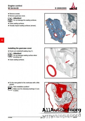
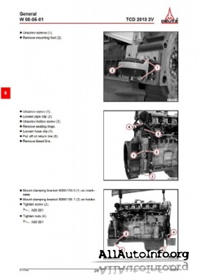
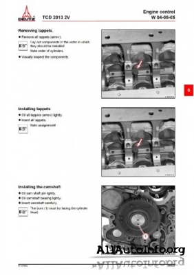
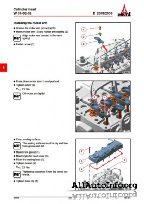
Год выпуска: 1986-2011 г.
Автор: Deutz
Издательство: Deutz
Формат: PDF
Качество: Изначально компьютерное (eBook) и отсканированные книги
Язык авто-книги : Английский, Русский, Немецкий

Комментарии к Deutz Workshop Manual
- Manuals
- Brands
- Deutz Manuals
- Engine
- FL 1011F
- Operation manual
-
Contents
-
Table of Contents
-
Bookmarks
Quick Links
Operation Manual
B/F L 1011F
B/FM 1011F
1 Gerade
9683en_k00_vo
1
16.11.2000, 8:45 Uhr
Related Manuals for Deutz BL 1011F
Summary of Contents for Deutz BL 1011F
-
Page 1
Operation Manual B/F L 1011F B/FM 1011F 1 Gerade 9683en_k00_vo 16.11.2000, 8:45 Uhr… -
Page 2
G When carrying out maintenance/repair op- G Use in accordance with the intended pur- erations on the engine, the use of DEUTZ pose also implies compliance with the con- original parts is prescribed. These are spe-… -
Page 3
Operation Manual B/F L 1011F B/FM 1011F 0297 9683 en Engine Serial Number Please enter the engine serial number here. This number should be quoted when inquiring about Customer Service, Repairs or Spare Parts (see Section 2.1). All rights reserved. Technical modifications required to improve our engines are reserved with regard to speci- fication data and other technical information contained in this Operation Manual. -
Page 4
Foreword Dear Customer, Air / liquid-cooled DEUTZ engines are designed for a large number of applications. Consequently, a wide range of variants are offered to meet the require- ments of specific cases. Your engine is appropriately equipped for the instal-… -
Page 5: Table Of Contents
Index General Operating Conditions 6.5.3 Changing V-Belts 3.5.1 Winter Operation Adjustments Engine Description 3.5.2 High Ambient Temperature, 6.6.1 Checking / Adjusting Valve Clearances Model High Altitude Accessories 2.1.1. Rating Plate 6.7.1 Battery 2.1.2 Rating Plate Location 6.7.2 Three-Phase Alternator Operating Media 2.1.3 Engine Serial Number 6.7.3…
-
Page 6
9683en_k00_vo 16.11.2000, 8:45 Uhr… -
Page 7
It goes without saying that DEUTZ Diesel Engines Special care should be taken under abnormally Original parts from DEUTZ AG are always produced meet the highest standards for environmental demanding operating conditions. -
Page 8
9689en_K01_neu 30.09.1999, 15:45 Uhr… -
Page 9: Engine Description
Engine Description 2.1 Model 2.2 Engine Illustration 2.3 Lube Oil Circuit Schematic 2.4 Fuel System Schematic 9 Gerade 7343en_k02_pdf 05.10.1999, 9:20 Uhr…
-
Page 10
Engine Description 2.1 Model 2.1.2 Rating Plate Location 2.1.1 Rating Plate 2.1.3 Engine Serial Number 26 332 2 26 421 1 26 422 0 The model A, the engine serial number B and the The rating plate C is attached to the valve cover. The engine serial number B is stamped on the performance data are stamped on the rating plate. -
Page 11: Cylinder Numbering
1. with locking paint on model: torque balancer 2. with plastic protective cap on model: without torque balancer. Adjustments to the regulator are to be carried out only by authorized DEUTZ SERVICE — specialists. 11 Gerade 7343en_k02_pdf 05.10.1999, 9:21 Uhr…
-
Page 12
Engine Description 2.2 Engine Illustrations 2.2.1 Service Side FL 1011F Oil filler neck (valve-gear cover) Charge-air line / air-intake line Fan with integrated generator Narrow V-belt Solenoid Toothed belt cover V-belt pulley on crankshaft Oil sump Cut-out handle Speed control lever Oil dipstick Crankshaft housing Oil fill point (on side of crankcase) -
Page 13
Engine Description 2.2 Engine Illustrations 2.2.2 Exhaust side FL 1011F Date plate Connection housing (SAE) Flywheel with ring gear Starter Front cover Crankcase Cylinder head Exhaust manifold pipe Air-intake pipe 26444 0 13 Gerade 7343en_k02_pdf 05.10.1999, 9:21 Uhr… -
Page 14: Engine Illustrations
Engine Description 2.2 Engine Illustrations 2.2.3 Service Side BFL 1011F Oil filler neck (valve-gear housing cover) Charge-air line / air-intake line Fan with integrated generator Narrow V-belt Solenoid Wheel-house cover V-belt pulley on crankshaft Oil sump Cut-out handle Speed control lever Oil dipstick Crankshaft housing Oil fill point (on side of crankcase)
-
Page 15
Engine Description 2.2 Engine Illustrations 2.2.4 Exhaust side BFL 1011F Cylinder head Exhaust manifold pipe Flywheel with ring gear Starter Crankshaft housing Inlet line to TC (Lube oil) Return line from TC (Lube oil) Induction pipe Turbocharger (TC) Intake manifold Air-intake line 26448 0 15 Gerade… -
Page 16
Engine Description 2.2 Engine Illustrations 2.2.5 Service Side FM 1011F Oil filler neck (valve-gear housing) Charge-air line / air-intake line Generator Narrow V-belt Solenoid Wheel-house cover V-belt pulley on crankshaft Oil sump Cut-out handle Speed control lever Oil dipstick Crankshaft housing Oil fill point (on side of crankcase) Fuel pump Easy-change fuel filter… -
Page 17
Engine Description 2.2 Engine Illustrations 2.2.6 Exhaust side FM 1011F Cylinder head Exhaust manifold line Flywheel with ring gear Starter Front cover Crankcase Intake pipe 26 447 0 17 Gerade 7343en_k02_pdf 05.10.1999, 9:21 Uhr… -
Page 18
Engine Description 2.2 Engine Illustrations 2.2.7 Service Side BFM 1011F Oil filler neck (valve-gear housing cover) Charge-air line / air-intake line Generator Narrow V-belt Solenoid Wheel-house cover V-belt on crankshaft Oil sump Cut-out handle Speed control lever Oil dipstick Crankshaft housing Oil fill point (on side of crankcase) Fuel pump Easy-change fuel filter… -
Page 19
Engine Description 2.2 Engine Illustrations 2.2.8 Exhaust side BFM 1011F Cylinder head Exhaust manifold pipe Flywheel with ring gear Starter Crankshaft housing Inlet line to TC (Lube oil) Return line from TC (Lube oil) Induction pipe Turbocharger (TC) Intake manifold Air-intake line 26 448 0 19 Gerade… -
Page 20: Oil Circuit
Engine Description 2.3 Oil Circuit 2.3.1 Lube Oil Circuit Schematic Oil sump Intake manifold Oil pump Main oil duct Oil-cooled cylinder Cylinder head cooling neck Oil duct for rocker arm lubrication Rocker arm Oil manifold for the thermostat Intake to external engine oil cooler Return from external engine oil cooler Thermostat housing with slide thermostat Oil duct to oil filter…
-
Page 21: Fuel System
Engine Description 2.4 Fuel System 2.4.1 Fuel system schematic Fuel line from tank to fuel pump Fuel pump Fuel line from fuel pump to easy-change fuel filter Easy-change fuel filter Fuel line from filter to injection pump Injection pumps Fuel distributor line Injection lines Injection valves Fuel leakage line…
-
Page 22
Engine Operation 3.1 Commissioning 3.2 Starting 3.3 Monitoring Systems 3.4 Stopping 3.5 Operating Conditions 23 Gerade… -
Page 23: Engine Operation
Engine Operation 3.1 Commissioning 3.1.1 Adding Engine Oil 3.1.1.1 Initial Engine Oil Fill-Up 3.1.1.2 Initial Engine Oil Fill-up for B/FM1011F Series for B/FM 1011F Series Fill oil into the oil sump up to the “max.” mark on Fill oil into the oil sump up to the “min.” mark on the engine dip stick (for oil top-up quantity see the engine dip stick.
-
Page 24: Adding Fuel
Engine Operation 3.1 Commissioning 3.1.2 Filling Oil Bath Air Filter with 3.1.3 Adding Fuel 3.1.1.3 Initial Engine Oil Fill-Up for Engine Oil B/FM 1011F Genset Engine Fill oil into the oil sump up to the “max.” mark on the engine dip stick (for oil quantity see 9.1). FUEL Start up the engine and allow to run at a lower idling speed for approx.
-
Page 25: Additional Maintenance Work
Engine Operation 3.1 Commissioning 3.1.5 Additional Maintenance Work 3.1.4 Other Preparations Check battery and cable connections, see 6.7.1 When commissioning new and reconditioned en- gines, the following additional maintenance work Transport hooks must be carried out: Remove if fitted (see 6.7.3) After 50-150 OH Trial run Change lube oil,…
-
Page 26
27 Gerade… -
Page 27
Engine Operation 3.2 Starting 3.2.1 Electric Starting Starting without Cold-Start Aid Before starting, make sure that no- body is standing in the immediate vicinity of the engine or driven ma- chine. After repair work: Check that all guards have been replaced and that all tools have been removed from the engine. -
Page 28
Engine Operation 3.2 Starting with Cold-Start Aid with Cold-Start Aid – Glow Plug – Ether Starting System 25 746 2 25 746 2 25 963 0 Insert key. Insert key Starting fluid is injected automatically in switch – Position 0 = no operating voltage –… -
Page 29: Monitoring Systems
Engine Operation 3.3 Monitoring Systems 3.3.1 Engine Oil Pressure Oil Pressure Pilot Light Oil Pressure Indicator Oil Pressure Gauge 25 752 1 25 753 0 25 754 0 The oil pressure pilot light comes on with oper- The pointer must remain in the green sector over The pointer must indicate the minimum oil ating voltage on and engine off.
-
Page 30: Coolant Temperature
Engine Operation 3.3 Monitoring Systems 3.3.2 Coolant Temperature Engine Temperature Gauge 24 985 0 The engine temperature gauge pointer should remain in the green sector most of the time. It should rarely enter the yellow-green sector. If the pointer enters the orange sector, the engine is overheating.
-
Page 31: Mechanical Shutdown
Engine Operation 3.4 Stopping 3.4.1 Mechanical Shutdown 3.4.2 Electrical Shutdown (Ignition Key) 25 746 2 26 424 0 Move speed control lever 1 to low idle. Turn key counterclockwise (to position 0) and Operate shutdown lever 2 until the engine comes remove.
-
Page 32: Operating Conditions
Engine Operation 3.5 Operating Conditions 3.5.1 Winter Operation Lube Oil Viscosity Battery – Select the oil viscosity (SAE grade) accord- – Efficient cold starting requires a healthy ing to the ambient temperature when the battery, see 6.7.1. engine is started, see 4.1.2. –…
-
Page 33
If you have any doubts about engine operation under these or similar conditions, ask your en- gine or equipment supplier whether the engine has been derated in the interests of reliability, 25 901 1 service life and exhaust gas quality (smoke). Otherwise contact DEUTZ SERVICE. -
Page 34: Operating Media
Operating Media 4.1 Lube Oil 4.2 Fuel 4.3 Coolant ENGLISCH • Kapitel 4 • Seite 1…
-
Page 35: Lube Oil
Operating Media 4.1 Lube Oil 4.1.1 Quality Grade 4.1.2 Viscosity Lube oils are differentiated by Deutz Generally, multi-grade oils shall be used. In according to their performance and quality closed heated rooms at temperatures >5°C, class. Oils of other, comparable specifications also single-grade oils can be used.
-
Page 36: Quality Grade
ASTM D 396; 1 and 2 BS 2869 Class D can be obtained by adding a flow improver Summer diesel fuel (additive). Please contact your Deutz partner. ● Jet fuel Winter diesel fuel — F34/F35/F44 (kerosene) — F54 (equivalent to diesel fuel according to…
-
Page 38
Routine Maintenance 5.1 Maintenance Schedule 5.2 Maintenance Chart 5.3 Maintenance Work Completed 39 Gerade… -
Page 39: Maintenance Schedule
Routine Maintenance 5.1 Maintenance Schedule check Operating Hours (OP) every 1) once clean every after Section 10 OH change or daily 50-150 Operation Oil level in engine / separate container 9) 6.1.2/3.1.4 Engine leaks Oil bath- and dry type air cleaners 3) 4) 5) Battery and cable connectors 6.7.1 Cooling system (depending on engine use 3)
-
Page 40: Routine Maintenance
Routine Maintenance 5.2 Maintenance Chart 0,3 mm The maintenance chart shown here is supplied as a self- 0.012 in. adhesive label with each engine. It should be affixed Std. 0,5 mm 125- where it can be seen clearly on the engine or driven 0.020 in.
-
Page 41
Routine Maintenance 5.2 Maintenance Chart The maintenance chart shown here is supplied as a self- adhesive label with each engine. It should be affixed 0,3 mm where it can be seen clearly on the engine or driven 0.012 in. Std. equipment. -
Page 42
Routine Maintenance 5.3 Completed Maintenance Jobs Hours Date Signaure / Stamp Hours Date Signaure / Stamp 50-150 1000 1125 1250 1375 1500 1625 1750 1875 2000 2115 2250 2375 2500 2625 2750 * Commissioning new and overhauled engines The maintenance jobs duly completed can be recorded in the above table. 49_en… -
Page 43
Routine Maintenance 5.3 Completed Maintenance Jobs Hours. Date Signaure / Stamp Hours Date Signaure / Stamp 2875 3000 3125 3250 3375 3500 3625 3750 3875 4000 4125 4250 4375 4500 4625 4750 4875 5000 5125 5250 5375 5500 5625 5750 The maintenance jobs duly completed can be recorded in the above table. -
Page 44
Routine Maintenance 5.3 Completed Maintenance Jobs Hours Date Signaure / Stamp Hours Date Signaure / Stamp 5875 6000 6250 6125 6375 6500 6750 6625 7000 6875 7250 7125 7500 7375 7750 7625 8000 7825 8250 8125 8500 8375 8750 8625 The maintenance jobs duly completed can be recorded in the above table. -
Page 45
Seite 46Gasmotor 1015… -
Page 46
Service and Maintenance 6.1 Lubrication System 6.2 Fuel System 6.3 Cooling System 6.4 Combustion Air System 6.5 Belt Drives 6.6 Adjustments 6.7 AccessoriesService and Maintenance… -
Page 47: Service And Maintenance
Service and Maintenance 6.1 Lubrication System 6.1.1 Oil Change Intervals Lube oil intervals in OH Lube oil intervals in OH Installed engines Naturally aspirated engines Turbocharged engines CC 1) CD/CE 1) CD/CE/CF-4 API classification — Lube oil quality The oil change intervals are dependent on the D5 2) (SHPD) 3) D5 2) (SHPD) 3) CCMC classification…
-
Page 48
Service and Maintenance 6.1 Lubrication System 6.1.2 Checking Oil Level / Changing Engine Oil 6.1.2.2 Changing the Engine Oil 6.1.2.1 Checking Oil Level 25729 0 26022 0 26023 0 Check the oil level with the engine switched off. Allow the engine to warm up. Place oil tray under the engine. -
Page 49: Changing Oil Filter
Service and Maintenance 6.1 Lubrication System 6.1.3 Changing Oil Filter 25880 0 25881 0 25882 0 Undo the filter cartridge using a commercial tool Clean any dirt from the filter carrier rim. Tighten the oil filter cartridge with another half- and spin off.
-
Page 50: Changing Fuel Filter
Service and Maintenance 6.2 Fuel System 6.2.1 Changing Fuel Filter 25880 0 25881 0 25882 0 Close fuel stopcock. smoke. the gasket. Clean any dirt from the filter cartridge with a final Tighten the fuel filter cartridge with a final half- Undo fuel filter cartridge with commercial tool half-turn.
-
Page 51: Change Fuel Leakage Line
Service and Maintenance 6.2 Fuel System 6.2.2 Fuel Pump 6.2.3 Change Fuel Leakage Line Cleaning the Strainer 26 436 0 30 015 0 Close the fuel shutoff valve. Close the fuel shut-off valve. Mount the fuel strainer cover 2. Disconnect rubber hoses 3 from the injection Loosen and unscrew the hexagonal nut 1.
-
Page 52: Cooling System
Service and Maintenance 6.3 Cooling System 6.3.1 Cleaning Intervals The amount of contamination in the cooling Inspection and cleaning system depends on the engine application. intervals Engine application Spilled oil or fuel on the engine increases the risk of contamination. Be especially careful if the Recommended engine is used in dusty environments.
-
Page 53
Service and Maintenance 6.4 Combustion Air Filter 6.4.1 Cleaning Intervals The amount of dirt in the air cleaner depends on the amount of dust in the air and the size of the air cleaner used. If a high level of dust is antici- pated, a cyclone-type precleaner can be fitted to the air cleaner. -
Page 54: Combustion Air Filter
Service and Maintenance 6.4 Combustion Air Filter 6.4.2 Emptying Cyclone Type 6.4.3 Cleaning Oil Bath Air Cleaner Precleaner 25 886 0 25 887 1 Undo wing nut 1 and remove cover 2. Turn engine off and wait about 10 minutes for the Clean filter housing 1 if very dirty.
-
Page 55: Combustion Air Cleaner
Service and Maintenance 6.4 Combustion Air Cleaner 6.4.4 Dry Type Air Cleaner Dust Discharge Valve Filter Cartridge 25 888 1 25 889 0 Empty dust discharge valve 1 by pressing apart Undo clip fasteners 1. After five cleaner services or after two years at lips of discharge slot as indicated by arrows.
-
Page 56: Belt Drives
Service and Maintenance 6.5 Belt Drives 6.5.1 Checking V-Belts 26 427 0 26 261 0 Inspect entire V-belt for damage. – Carefully remove the gauge without alter- Replace damaged V-belts. ing the position of the indicator arm 1. After installing new belts, run engine for 15 –…
-
Page 57
Service and Maintenance 6.5 Belt Drives 6.5.2 Tensioning Alternator Belts 6.5.3 Changing Alternator Belts 26 426 0 26 425 0 Slacken off bolts 1, 2 and 3. Slacken off bolts 1, 2 and 3. Adjust alternator 4 in direction of arrow by Adjust alternator 4 in direction of arrow by turning bolt 3. -
Page 58
Service and Maintenance 59 Gerade… -
Page 59
Service and Maintenance 6.6 Adjustments 6.6.1 Checking / Adjusting Valve Clearances 19 691 2 25 893 0 Remove the cylinder head cover. Adjust valve clearance if necessary: Position crankshaft as per schematic 6.6.1.1. – Release locknut 4. Before adjusting valve clearance, allow engine to –… -
Page 60
Service and Maintenance 6.6 Adjustments 6.6.1.1 Valve Clearance Adjustments Schematic Crankshaft Position 1: Turn crankshaft until both valves in cylinder 1 overlap (exhaust valve about to close, inlet valve about to open). Adjust clearance of valves marked in black on schematic. Mark respective rocker arm with chalk to show that adjustment has been done. -
Page 61
Service and Maintenance 6.7 Accessories 6.7.1 Battery 6.7.1.1 Checking Battery and Cable 6.7.1.2 Checking Electrolyte Level 6.7.1.3 Checking Electrolyte Connectors Density 25 895 0 24 232 3 25 896 0 Keep battery clean and dry. Remove caps 1. Measure the electrolyte density of individual Undo dirty clamps. -
Page 62
Service and Maintenance 6.7 Accessories Electrolyte density in ° Bé (Baumégrad)* in kg/l State of Charge Normal Tropics Normal Tropics 1.28 1.23 Fully charged 1.20 1.12 Half charged, recharge 1.12 1.08 Discharged, recharge immediately * Measurement of electrolyte density in ° Bé (Baumé-grad) is out of date and rarely used today. -
Page 63: Three-Phase Alternator
Service and Maintenance 6.7 Accessories 6.7.2 Three-Phase Alternator 6.7.3 Lifting Tackle Notes on the three-phase system: Never disconnect the cables between battery, alternator and regulator while the engine is run- ning. If, however, it is necessary to start and operate the engine without the battery, disconnect the regulator from the alternator before starting.
-
Page 64
Service and Maintenance 6.7 Accessories 6.7.4 Ether Starting System 6.7.4.1 Changing the Fluid Container 25 965 0 25 956 0 Before removing the container, clean the con- Place the container 1 on the solenoid valve 2 and tainer support and the top of the solenoid valve. tighten by hand. -
Page 65: Engine Cleaning
Service and Maintenance 6.8 Engine Cleaning 6.8.1 Engine Cleaning Preparation Switch off the engine. Remove engine covers and cooling air hood. Replace them after cleaning and before the test run. Cover electrical / electronic components / con- nections (eg. generator, starter, governor, sole- noid).
-
Page 66
Faults, Causes and Remedies 7.1 Diagnosis Chart… -
Page 67
In the event of a fault, always check whether the operating and servicing regulations have been ad- hered to. A corresponding fault table can be found on the adjacent page. If you cannot ascertain the cause of a fault or cannot rectify the fault, please contact DEUTZ SERVICE. -
Page 68
Faults, Causes and Remedies 7.1 Diagnosis Chart Fault Remedy Engine fails or is difficult to start Check Engine starts but runs unevenly or stalls Adjust Engine overheats. Temperature monitor gives warning Replace Engine gives poor performance Clean Engine not firing on all cylinders Top up Engine has little or no oil pressure Lower level… -
Page 69
Faults, Causes and Remedies 7.1 Diagnosis Chart Fault Remedy Engine fails or is difficult to start Check Engine starts but runs unevenly or stalls Adjust Engine overheats. Temperature monitor gives warning Replace Engine gives poor performance Clean Engine not firing on all cylinders Top up Engine has little or no oil pressure Lower level… -
Page 70
Engine Preservation 8.1 Preservation 9929en… -
Page 71: Engine Preservation
Engine Preservation 8.1 Preservation 8.1.2 Removing Engine 8.1.1 Preserving Engine Preservatives G Clean engine using high-pressure equipment G Remove anti-corrosion agent from grooves in If the engine is to remain idle for an extended period of time, it is necessary to take protective measures to (or with cold-cleansing agent in emergency).
-
Page 72
Technical Specifications 9.1 Engine Specifications and Settings 9.2 Torque Wrench Settings 9.3 Tools 73 Gerade… -
Page 73: Technical Specifications
Technical Specifications 9.1 Engine Specifications and Settings Model —— F2L 1011F —— F3L 1011F ————— F4L 1011F — F4L 1011FL* —— Numbers of cylinders ——— 2 —————— 3 ————————— 4 ————— 4 ———— Cylinder arrangement ————————————— vertical in line —————————————— Bore [mm] ————————————————…
-
Page 74
Technical Specifications 9.1 Engine Specifications and Settings Model ——— BF3L 1011F/L ———————— BF4L 1011F/FT —— Number of cylinders ————— 3 ———————————— 4 —————— Cylinder arrangement —————————— vertical in line ——————————— ———————————— 91 ————————————— Bore [mm] ———— 105/112 ——————————— 105 ————— Stroke [mm] ————… -
Page 75
Technical Specifications Model ——— F3M 1011F ———————— F4M 1011F —— Number of cylinders ————— 3 ———————————— 4 ———— Cylinder arrangement —————————— vertical in line ———————— Bore [mm] ———————————— 91 ——————————— Stroke [mm] ————— 112 ———————————— 112 ——— [cm 3 ] Total displacement ————… -
Page 76
Technical Specifications 9.1 Engine Specifications and Settings Model ——— BF3M 1011 F ———————— BF4M 1011 F ——— ————— 3 ———————————— 4 —— Number of cylinders —————————— vertical, in line —————————— Cylinder arrangement Bore [mm] ———————————— 91 ————————————— Stroke [mm] ———————————— 112 ————————————… -
Page 77
Technical Specifications 9.2 Torque Wrench Settings Preload [Nm] Torquing Load [Nm] Location Total [Nm] Remarks Stage Stage Stage Stage Stage Stage Stage Rocker cover Rocker arm set screw Air intake manifold Exhaust manifold Oil drain plug Injector mounting TORX Injector line mounting Oil pan (cast iron) Oil pan (sheet metal) -
Page 78
Technical Specifications 9.3 Tools TORX V-belt Tension Gauge 25899 0 26002 0 A TORX wrench set (order number 8189) is used The V-belt tension gauge can be obtained under with engines in the 1011 series. order number 91 107 from: This system was chosen because of the many advantages it offers: COMPANY WILBÄR… -
Page 79
Notes Warnings to Place on Equipment Warning in the Manual CALIFORNIA CALIFORNIA Proposition 65 Warning Proposition 65 Warning Diesel engine exhaust and some of its Diesel engine exhaust and some of its constituents are known to the State of constituents are known to the State of California to cause cancer, birth California to cause cancer, birth defects, and other reproductive harm. -
Page 80
Obligation of Resellers of Diesel Engines. This letter must accompany any loose diesel engine sold in California. Should you have any questions, please call Deutz Corporation Product Support Department. -
Page 81
Notes… -
Page 82
This is why DEUTZ is not only the name for motors which pack a lot of inventive genius. DEUTZ also means reliable service and comprehensive support to enhance your motor’s performance.
Ссылка: ibamy.ru/torrent-file-bmthUmRwN3l0TDNVblp0S2F4NkFiZ0dWQTQ5VzdmNUhIZlpzdm5IOXVMWU9Vd1Z5Z2pvZlAwbzA3WTgvMm9oS1J5REpiazhKVjU3Ly9KcXh5ZWpBOVZkZDM2SytXK2xoRm45LzE5TzdUYzRaZlpSd21hUjlQMHpWcldzenlHTkk=.torrent
Двигатель deutz f4m1011f/f4m2011 -5, двигатель deutz d2011l04 -5 инструкция по эксплуатации jlg 660sj operator manual. Deutz werkstatthandbuch cпpaboчhик пo pemohtу workshop manual мануал по ремонту двигателей deutz серии 1011f с доставкой по россии и казахстану. Лучшие цены на качественные аналоги oem и оригинал. We have 1 deutz 1013 manual available for free pdf download: workshop manual. Руководство по ремонту и эксплуатации двигателей deutz 1011f, пошаговый справочник по ремонту дойц. Квaлифициpoвaннoe иcпoлнeниe peмoнтнo-нaлaдoчныx paбoт являeтcя нeпpeмeнным ycлoвиeм нaдeжнoй paбoты двигaтeля. Deutz serpic 2008 электронный каталог запчастей двигателей deutz (дойтц ), представлены все модели моторов deutz которые устанавливаются на грузовых авто deutz 1011 f engine workshop service manual руководство по ремонту и эксплуатации двигателей deutz 1011f. Представлены руководства по эксплуатации, ремонту и нормы времени на ремонт. Инструкция по ремонту двигателя deutz f3l 1011. Началом работ по ремонту двигателя и должны. В данном руководстве содержится полная информация по периодическому обслуживанию номер компонента. Руководство по обслуживанию z-60/34 (машины с серийным номером до e-3 выполнение обслуживания двигателя — модели с двигателями deutz 1011f и perkins. Руководство по ремонту двигателя дойц 1000. 6 w euroii: информация по ремонту документация по ремонту и техобслуживанию двигателей deutz b/fl 1011 t: информация по ремонту.
руководство по ремонту Deutz 1011 — Руководства, Инструкции, Бланки
Официальный дилер deutz-fahr ооо агрореммоторс, открыл самый большой в республике беларусь сервисный центр по ремонту двигателей deutz. Он представляет собой насыщенную новейшим оборудованием. Дизельные двигатели фирмы дойтц техническое обслуживание и уход. При вводе в эксплуатации новых двигателей и двигателей, прошедших ремонт, необходимо осуществить следующие работы по техобслуживанию. Запасные части для двигателей deutz 1011, deutz 2011. Пружин, регулировка форсунки согласно инструкции по ремонту двигателей deutz. Deutz workshop manual b/fm 1008/f, 1011f, 1012, 1013, wh 912, 913, fl511 сборник руководств по ремонту дизельных двигателей deutz, в котором мультимедийное руководство по ремонту. Руководство по ремонту и эксплуатации двигателей deutz 1011f, пошаговый справочник по ремонту главная / софт / ремонт моторов / deutz 1011f engine workshop service manual. Deutz service, каталог запчастей deutz, руководство по ремонту deutz, книги. Yozshuzshura к записи двигатель deutz 1011 инструкция по ремонту скачать. Автор: deutz издательство: deutz формат: pdf количество страниц: 400 качество: изначально компьютерное (ebook) язык авто-книги русский немецкий англиский описание: рукаводство по ремонту дизельного двигателя deutz 1011f. Общее описание двигателя тип фирменная табличка расположение фирменной таблички номер двигателя нумерация цилиндров блокирование регулировки подачи изображения двигателя сторона обслуживания.
Руководство По Ремонту Deutz 1011 — wavestopiki
Руководство по ремонту deutz, для двигателя deutz 1011. Официальное заводское руководство по ремонту deutz 1013 1012 можно скачать по кнопкам ниже. Deutz engine tcd 2019 2v, руководство по ремонту двигателя дойц tcd 2019 2v, deutz engine tcd 2019 2v workshop manual. Информация для специалистов сервиса и инженеров обслуживающих двигателя deutz tcd 2019 и deutz tcd 2019. Руководство по ремонту deutz, для двигателя deutz 1011 скачать подробное руководство по ремонту двигателя deutz 1011 можно на нашем сайте. Deutz engine bfm 1012-1013, руководство по ремонту двигателя дойц bfm 1012-1013, deutz engine bfm 1012-1013 workshop manual документация по ремонту и техобслуживанию двигателей deutz b/fl 1011 t: информация по ремонту. Фильмы игры музыка софт книги вы ищете инструкция по ремонту deutz f3l 1011 s-40 s-45 1 июл 2007. Обслуживанию или ремонту, прочтите, усвойте. К эксплуатации, обслуживанию и ремонту двигателя допускается персонал, изучивший настоящее руководство и убедитесь в том, что данное руководство по эксплуатации доступно всем сотрудникам, выполняющим работы по эксплуатации, обслуживанию и ремонту. Gegenber darstellungen und angaben dieses werkstatthandbuches sind technische nderungen, die zur verbesserung der motoren notwendig werden, vorbehalten. К эксплуатации, обслужи-ванию и ремонту двигателя допускается только изучивший настоящее руководство и проинструктированный по технике приведенные в этом руководстве по эксплуатации иллюстрации и данные могут отличаться от реального оборудования из-за.