Код: 126083
53 090
рублей
Бесплатная доставка
по Красноярску
?
в наличии
в Красноярске
Новости интернет-магазина «Лаукар»:
Дополнительная информация в категории Электропила:
В интернет-магазине бытовой техники «Лаукар» Вы можете скачать инструкцию к товару Пила дисковая DeWALT DWE7485-QS совершенно бесплатно.
Все инструкции, представленные на сайте интернет-магазина бытовой техники «Лаукар», предоставляются производителем товара.
Перед началом использования товара рекомендуем Вам ознакомиться с инструкцией по применению.
Для того чтобы скачать инструкцию, Вам необходимо нажать на ссылку «скачать инструкцию», расположенную ниже, а в случае, если ссылки нет,
Вы можете попробовать обратиться к данной странице позднее,
возможно специалисты интернет-магазина бытовой техники «Лаукар» еще не успели загрузить для скачивания инструкцию к товару:
Пила дисковая DeWALT DWE7485-QS.

Фирма-производитель оставляет за собой право на внесение изменений в конструкцию, дизайн и комплектацию товара: Пила дисковая DeWALT DWE7485-QS. Пожалуйста, сверяйте информацию о товаре с информацией на
официальном сайте компании производителя.
Документы — настольная пила DeWalt DWE7485-QS
Арт. О00000021005
5.0
3

Найти аналог
Нет в наличии
3 года гарантии
Арт. О00000021005
5.0
3
Характеристики
|
Производитель |
|
|
Мощность, Вт |
1850 |
|
Напряжение сети, В |
220 |
|
Число оборотов, об/мин |
5800 |
|
Диаметр пильного диска, мм |
210 |
|
Посадочный диаметр пильного диска, мм |
30 |
|
Тип электродвигателя |
щеточный |
|
Макс. глубина пропила, мм |
65 |
Все характеристики
Найти аналог
Нет в наличии
3 года гарантии
Описание
Характеристики и комплектация
Документы
Рейтинги и отзывы
Статьи и обзоры
-
-
Инструкция DeWalt DWE7485-QS
Инструкция.pdf 5.44 МБ
-
- Manuals
- Brands
- DeWalt Manuals
- Saw
- DWE7485
- Instruction manual
-
Contents
-
Table of Contents
-
Bookmarks
Quick Links
Instruction Manual
Guide D’utilisation
Manual de instrucciones
DWE7485
Table Saw
Scie de table
Sierra de Banco
If you have questions or comments, contact us.
Pour toute question ou tout commentaire, nous contacter.
Si tiene dudas o comentarios, contáctenos.
1-800-4-D
WALT
e
Related Manuals for DeWalt DWE7485
Summary of Contents for DeWalt DWE7485
-
Page 1
Instruction Manual Guide D’utilisation Manual de instrucciones DWE7485 Table Saw Scie de table Sierra de Banco If you have questions or comments, contact us. Pour toute question ou tout commentaire, nous contacter. Si tiene dudas o comentarios, contáctenos. 1-800-4-D WALT… -
Page 2
English (original instructions) Français (traduction de la notice d’instructions originale) Español (traducido de las instrucciones originales) -
Page 3
English Definitions: Safety Alert Symbols and Words This instruction manual uses the following safety alert symbols and words to alert you to hazardous situations and your risk of personal injury or property damage. DANGER: Indicates an imminently hazardous situation which, if not avoided, will result in death or serious injury. WARNING: Indicates a potentially hazardous situation which, if not avoided, could result in death or serious injury. -
Page 4: General Power Tool Safety Warnings
English Table Saw DWE7485 GENERAL POWER TOOL SAFETY WARNINGS power tool’s operation. If damaged, have the power tool repaired before use. Many accidents are caused by poorly maintained power tools. WARNING: Read all safety warnings, instructions, illustrations and specifications f ) Keep cutting tools sharp and clean. Properly maintained cutting tools with sharp cutting provided with this power tool.
-
Page 5: Kickback Causes And Related Warnings
English j ) Feed workpiece at an even pace. Do not bend or twist the workpiece. If jamming j ) Make sure that the saw blade is installed to rotate in the proper direction. Do not occurs, turn the tool off immediately, unplug the tool then clear the jam. Jamming use grinding wheels, wire brushes, or abrasive wheels on a table saw.
-
Page 6: Specifications
English Saw Blades n ……rated speed ….. wear respiratory protection Do not use saw blades that do not conform to the dimensions stated in the specifications……. earthing terminal • ….. wear eye protection Do not use any spacers to make a blade fit onto the spindle. Use only the blades specified in this …..
-
Page 7
English nOTE: To attach this table saw to a stand, please follow the instructions included with the nOTE: The saw is shipped with the non-through-cutting riving knife installed. stand assembly. 1. Raise the saw blade arbor to its maximum height. Installing the Throat Plate (Fig. C) 2. -
Page 8: Assembly And Adjustments
English WARNING: To reduce the risk of serious personal injury, turn unit off and disconnect Fig. F it from power source before making any adjustments or removing/installing attachments or accessories. An accidental start-up can cause injury. WARNING: To reduce the risk of injury, the saw must be secured to prevent unintended movement during use.
-
Page 9
English 1. Using a 5 mm hex wrench, loosen rear pivot bracket fasteners 38 just enough to allow the 3. Locate the three small set screws 42 adjacent to the riving knife lock knob 30 . These screws bracket to move side-to-side. will be used to adjust the riving knife position. -
Page 10: Operation
Push green button 44 in to turn this saw on and push down the red paddle to turn this www.dewalt.com saw off. If a different blade is used and the body thickness and kerf width dimensions are not provided, Lock Off Feature Instructions use the following procedure to determine the correct riving knife thickness: A cover above the switch folds down for insertion of a padlock to lock the saw off.
-
Page 11
English nOTE: This fence will allow the guard to remain on the saw when completing narrow ripping. Fig. S This fence will provide ample space for a push stick. Fine Adjustment Knob (Fig. A) The fine adjustment knob 4 allows smaller adjustments when setting the fence. Before adjusting, be sure the rail lock lever is in its up or unlocked position. -
Page 12: Compound Mitering
English Non-Through-Ripping Small Pieces (Fig. A) Fig. T It is unsafe to rip small pieces. It is not safe to put your hands close to the blade. Instead, rip a larger piece to obtain the desired piece. When a small width is to be ripped and the hand cannot be safely put between the blade and the rip fence, use one or more push sticks.
-
Page 13
English Non-Through-Compound Mitering Fig. Z This is a combination of non-through-bevel crosscutting and non-through-mitering. Follow the instructions for both non-through-bevel crosscutting and non-through-mitering. Dust Collection (Fig. A, X) This table saw is equipped with a guard dust collection port 14 and a dust collection port … -
Page 14: Maintenance
Dust extraction Y connector (contact your local dealer) Fig. CC ** The DWE74911 stand is ONLY compatible with the DWE7485 if purchased separately. When purchased with the original DWE7491RS saw, the stand DOES NOT include the necessary adapter brackets for the DWE7485.
-
Page 15
FRAnçAis Définitions : symboles et termes d’alarmes sécurité Ces guides d’utilisation utilisent les symboles et termes d’alarmes sécurité suivants pour vous prévenir de situations dangereuses et de risques de dommages corporels ou matériels. DANGER : indique une situation dangereuse imminente qui, si elle n’est pas évitée, entraînera la mort ou des blessures graves. AVERTISSEMENT : indique une situation potentiellement dangereuse qui, si elle n’est pas évitée, pourrait entraîner la mort ou des blessures graves. -
Page 16
FRAnçAis Scie de table DWE7485 AVERTISSEMENTS GÉNÉRAUX SUR LA SÉCURITÉ DES OUTILS b ) Ne pas utiliser un outil électrique dont l’interrupteur est défectueux. Tout outil électrique dont l’interrupteur est défectueux est dangereux et doit être réparé. AVERTISSEMENT : lisez tous les avertissements de sécurité, toutes les instructions, c ) Débranchez la fiche de la prise électrique et, si amovible, retirez le bloc-piles de… -
Page 17
FRAnçAis servez-vous d’un bloc-poussoir. Les moyens d’assistance au travail garderont vos mains à 4) Procédures de fonctionnement du banc de scie une distance sécuritaire de la lame. (avertissements) e ) N’utiliser que le bâton-poussoir fourni ou un bâton fabriqué selon les mesures a ) Lors du retrait du dessus de table, du remplacement de lame de scie ou pour faire le données. -
Page 18: Lames De Scie
FRAnçAis NE JAMAIS TENTER DE LIBÉRER UNE LAME BLOQUÉE AVANT D’AVOIR ARRÊTÉ LA SCIE • systématiquement un appareil de protection des voies respiratoires homologué par le NIOSH ET RETIRÉ LE SOURCE D’ÉNERGIE. Si un morceau ou un rebut restait coincé dans le dispositif ou l’OSHA.
-
Page 19: Description (Fig. A)
FRAnçAis Retrait de la plaque de lumière Fig. B 1. Retirez la plaque de lumière 15 en tournant le bouton de verrouillage de came 24 d’un quart de tour vers la gauche. 2. En utilisant le trou passe-doigt 26 sur la plaque, tirez la plaque de lumière vers le haut et l’avant pour exposer l’intérieur de la scie.
-
Page 20
FRAnçAis Fig. E 4. Desserrez les vis de l’indicateur d’échelle de coupe 33 et réglez l’indicateur d’échelle de coupe sur zéro (0). Resserrez les vis de l’indicateur d’échelle de coupe. La lecture de 3 l’échelle de coupe jaune (supérieure) est valide seulement lorsque le guide est installé à droite de la lame et sur la position 1 [coupe longitudinale de 0 à… -
Page 21: Assemblage Et Ajustements
FRAnçAis ASSEMBLAGE ET AJUSTEMENTS 7. Vérifiez l’échelle d’angle de biseau. Si l’indicateur n’est pas sur 0°, desserrez la vis de l’indicateur et ajustez l’indicateur sur le bon angle. Resserrez la vis de l’indicateur. 40 AVERTISSEMENT : afin de réduire le risque de blessure corporelle, éteignez l’appareil 8.
-
Page 22
Les dimensions d’épaisseur de corps de lame et de largeur de traits de scie pour toutes les lames de scie de table D WALT sont disponibles sur le site www.dewalt.com. l’interrupteur est en position d’ARRÊT avant de brancher la machine. -
Page 23
FRAnçAis Utilisation de la fonctionnalité de verrouillage Bouton de réglage de précision (Fig. A) Un capot au-dessus de l’interrupteur se rabat pour permettre l’insertion d’un cadenas pour Le bouton de réglage de précision 4 permet d’effectuer des réglages de précision sur le verrouiller la scie à… -
Page 24
FRAnçAis AVERTISSEMENT : certaines formes de pièces, comme les moulures, peuvent ne pas le guide, et pousser complètement la pièce au-delà de la lame. Le guide longitudinal étroit de soulever le dispositif de carter de lame correctement. Alimentez la pièce lentement pour cette scie de table peut être utilisé… -
Page 25
FRAnçAis Fig. U 6. Ne jamais tenter de ramener la pièce de travail alors que la scie tourne. Coupez l’alimentation, laissez la scie s’arrêter et retirez délicatement la pièce. Coupe transversale non part-en-part biseautée Cette opération est la même qu’une coupe transversale sauf que l’angle de la lame est différent que le réglage de zéro degrés (0°). -
Page 26
FRAnçAis Lubrification (Fig. Y) • Avant les déplacements, verrouillez le guide en place, abaissez la lame et verrouillez le biseau. • Toujours se servir des poignées 22 pour transporter la machine.. 1. Les roulements du moteur sont lubrifiés de façon permanente en usine et aucune autre lubrification n’est nécessaire. -
Page 27
Les accessoires recommandés pour cet outil sont vendus séparément au centre de service de votre région. Pour obtenir de l’aide concernant l’achat d’un accessoire, communiquer avec WALT , composer le 1 800 433-9258 (1 800 4-D WALT) ou visiter notre site Web : www.dewalt. com. •… -
Page 28
EsPAñOl Definiciones: Símbolos y Palabras de Alerta de Seguridad Este manual de instrucciones utiliza los siguientes símbolos y palabras de alerta de seguridad para alertarle de situaciones peligrosas y del riesgo de lesiones corporales o daños materiales. PELIGRO: Indica una situación de peligro inminente que, si no se evita, provocará la muerte o lesiones graves. ADVERTENCIA: Indica una situación de peligro potencial que, si no se evita, podría provocar la muerte o lesiones graves. -
Page 29
EsPAñOl Sierra de Banco DWE7485 ADVERTENCIAS GENERALES DE SEGURIDAD PARA HERRAMIENTAS 4) Uso y Mantenimiento de la Herramienta Eléctrica a ) No fuerce la herramienta eléctrica. Utilice la herramienta eléctrica correcta para ELÉCTRICAS el trabajo que realizará. Si se la utiliza a la velocidad para la que fue diseñada, la ADVERTENCIA: Lea todas las advertencias de seguridad, instrucciones, ilustraciones herramienta eléctrica correcta permite trabajar mejor y de manera más segura. -
Page 30
EsPAñOl b ) Alimente la pieza de trabajo con la hoja de la sierra o el cortador sólo contra la inestable y causa un desalineamiento de la ranura con la cuchilla de la sierra, atascamiento dirección de rotación. Alimentar la pieza de trabajo en la misma dirección en que la y retroceso. -
Page 31
Más de Más de inmediatamente, apáguela y saque la batería hasta que se haya identificado y corregido el problema. Contacte con un centro de servicio de fábrica de DeWalt, un centro de servicio autorizado de D WALT u otro personal de servicio calificado si no puede identificarse el problema. -
Page 32: Uso Debido
EsPAñOl Especificaciones Instalación de la Placa de Garganta (Fig. C) 1. Alinee la placa de garganta 15 como se muestra en la Figura C, e inserte las lengüetas de Tamaño del banco 485 x 485 mm (19 x 19″) la parte posterior de la placa de garganta en los orificios en la parte posterior de la abertura Ángulo de inglete 30°…
-
Page 33
EsPAñOl Instalación/Retiro de la Unidad del Protector de la Hoja y el Cuchillo Fig. F Separador (Fig. E) ATENCIÓN: Use el ensamble de la protección de cuchilla para todo el corte completo. nOTA: La sierra se envía con el cuchillo de corte sin corte completo instalado. 1. -
Page 34: Montaje Y Ajustes
EsPAñOl Montaje Sobre Banco (Fig. A) ADVERTENCIA: Para reducir el riesgo de lesiones personales, apague la unidad y desconéctela de la fuente de energía antes de realizar cualquier ajuste o retirar/ nOTA: Un soporte de sierra de banco portátil está diseñado para ser utilizado con esta sierra y instalar conexiones o accesorios.
-
Page 35: Operación
D WALT pueden encontrarse en www.DEWALT.com. 10. Repita el paso 4 para verificar la posición del cuchillo separador. Repita los pasos 5 a 7 si Si se utiliza una hoja diferente y las dimensiones del espesor de cuerpo y el ancho de línea es necesario.
-
Page 36
EsPAñOl nOTA: Jale la unidad anti-rebote para asegurarse de que se haya bloqueado en su sitio. • Si se está realizando un corte longitudinal, asegúrese de que la palanca de bloqueo de la siEMPRE asegúrese de que ambos protectores están en su posición baja en contacto con el guía esté… -
Page 37
EsPAñOl ADVERTENCIA: Cuando se hagan cortes longitudinales biselados y siempre que sea posible, alcance el cuchillo de desgarre, apague la unidad y desconecte la máquina de la fuente de coloque la guía a un lado de la hoja para que esta esté inclinada alejada de la guía y de energía. -
Page 38
EsPAñOl Fig. T 8. Cuando corte una pieza larga de material o un tablero, siempre use un soporte de trabajo. Un caballete, rodillos, o ensamble de salida de alimentación proporcionan un soporte adecuado para este propósito. El soporte de trabajo debe estar a la misma altura o ligeramente debajo que el banco de sierra. -
Page 39
EsPAñOl . Consulte la sección Instalación/retiro de la Fig. W 4. Retire la unidad del protector de la hoja 11 unidad del protector de la hoja y el cuchillo separador . Coloque la unidad del protector de la hoja en el sujetador como se muestra, luego gire la perilla de bloqueo 1/4 de vuelta para bloquearla en su sitio. -
Page 40: Mantenimiento
D WALT, llame al 1-800-4-D WALT guía auxiliar para cortes delgados en todo momento. (1-800-433-9258) o visite nuestro sitio web: www.dewalt.com. iMPORTAnTE: La guía auxiliar para cortes delgados y el borde que sobresale 47 (Fig. BB) deben •…
-
Page 41: Especificaciones
Esta garantía no cubre falla de partes debido al desgaste normal o abuso de la herramienta. Para detalles adicionales de la cobertura de la garantía e información de reparación de garantía, visite www.dewalt.com o llame al 1-800-4-D WALT (1-800-433-9258).
-
Page 44
WALT Industrial Tool Co. 701 East Joppa Road, Towson, MD 21286 Copyright © 2019 The following are trademarks for one or more D WALT power tools: the yellow and black color scheme, the “D” shaped air intake grill, the array of pyramids on the handgrip, the kit box configuration, and the array of lozenge-shaped humps on the surface of the tool.
2. Разблокируйте рычаг установки угла наклона
его вверх и повернув вправо. Ослабьте стопорный винт
ограничителя угла наклона
3. Приложите угольник горизонтально к столу и
вертикально к плоскости пильного диска, расположив
его между зубьями. Убедитесь, что рычаг установки
угла наклона разблокирован, т.е. находится в
верхнем положении.
4. При помощи рычага установки угла наклона
отрегулируйте угол наклона таким образом, чтобы
пильный диск оказался прижатым вплотную к угольнику.
5. Затяните рычаг установки угла наклона, опустив
его вниз.
6. Поворачивайте винт ограничителя угла наклона
тех пор, пока он вплотную не приблизится к опорному
блоку. Затяните винт ограничителя угла наклона.
7. Проверьте шкалу угла наклона. Если указатель не
указывает на отметку 0°, ослабьте винт указателя
и установите указатель на отметке. Затяните
винт указателя.
8. Повторите при 45°, но не регулируйте указатель.
Регулировка углового упора (Рис. A)
Чтобы отрегулировать угловой упор
рукоятку, установите нужный угол и снова затяните
зажимную рукоятку.
Положение тела и рук
Правильное положение тела и рук во время управления
настольной пилой сделает работу более лёгкой, точной
и безопасной.
ОСТОРОЖНО:
•
Никогда не держите руки в зоне распила.
•
Не подносите руки к диску ближе, чем на 150 мм.
•
Не перекрещивайте руки во время работы.
•
Твердо стойте на ногах, чтобы сохранять
надлежащий баланс.
Подготовка к эксплуатации
ОСТОРОЖНО:
•
Используйте пильный диск соответствующего
типа. Не используйте крайне изношенные
диски. Максимальная скорость вращения
инструмента не должна превышать скорость
вращения пильного диска.
•
Не пытайтесь распиливать очень
мелкие детали.
•
Не пытайтесь ускорить работу пильного диска.
Не прилагайте чрезмерных усилий.
•
Перед началом резки дождитесь, пока двигатель
наберет полные обороты.
, подняв
7
38
.
38
до
39
10
, ослабьте зажимную
ЭКСПЛУАТАЦИЯ
Инструкции по использованию
ВНИМАНИЕ: Всегда следуйте указаниям
действующих норм и правил безопасности.
ВНИМАНИЕ: Чтобы снизить риск получения
серьезных травм, выключайте инструмент
и отключайте его от сети перед тем,
как выполнять какие-либо настройки или
снимать/устанавливать насадки или
принадлежности. Случайный запуск может
привести к травме.
Чтобы уменьшить эффект вибрации, убедитесь в том, что
температура окружающей среды не была слишком низкой,
за инструментом и оснасткой был надлежащий уход, а
размер заготовки соответствовал инструменту.
ОСТОРОЖНО:
•
Всегда соблюдайте правила техники
безопасности и применимые законы.
•
Убедитесь в том, что инструмент расположен
оптимально с точки зрения эргономики, на
соответствующей высоте и в устойчивом
положении. Местоположение инструмента
должно быть выбрано так, чтобы у оператора
был хороший обзор и вокруг было достаточно
места, которое позволило бы удобно работать
с обрабатываемой деталью.
•
Используйте пильный диск соответствующего
типа. Не используйте изношенные диски.
Максимальная скорость вращения
инструмента не должна превышать скорость
вращения пильного диска.
•
Не пытайтесь распиливать очень
мелкие детали.
•
Не пытайтесь ускорить работу пильного диска.
Не прилагайте чрезмерных усилий.
•
Перед началом резки дождитесь, пока двигатель
наберет полные обороты.
•
Убедитесь в том, что все фиксаторы и зажимы
надежно закреплены.
•
Не держите руки рядом с диском в то
время, когда инструмент подключен к
источнику питания.
•
Запрещается выполнять распиловку «от руки»!
•
Распиловка неровных, изогнутых и вогнутых
заготовок запрещена. У заготовки должна
быть по меньшей мере одна прямая, гладкая
поверхность, которую необходимо приложить к
направляющей или угловому упору.
Pусский
29

PDF инструкция · 44 страниц(ы) английский
инструкцияDeWalt DWE7485

If you have questions or comments, contact us.
Pour toute question ou tout commentaire, nous contacter.
Si tiene dudas o comentarios, contáctenos.
1-800-4-
DeWALT
Instruction Manual
Guide D’utilisation
Manual de instrucciones
DWE7485
Table Saw
Scie de table
Sierra de Banco
Посмотреть инструкция для DeWalt DWE7485 бесплатно. Руководство относится к категории пилы, 9 человек(а) дали ему среднюю оценку 9. Руководство доступно на следующих языках: английский. У вас есть вопрос о DeWalt DWE7485 или вам нужна помощь? Задайте свой вопрос здесь
Главная
| DeWalt | |
| DWE7485 | DWE7485-QS | |
| пила | |
| 5035048723371 | |
| английский | |
| Руководство пользователя (PDF), Сведения о гарантии (PDF) |
Содержимое упаковки
| Толкатель | Да |
| Ключ для замены диска | Да |
| Режущий диск в комплекте | Да |
Вес и размеры
| Вес | 22000 g |
| Диаметр диска | 210 mm |
| Диаметр отверстия шпинделя | 30 mm |
| Ширина стола | 485 mm |
| Глубина стола | 485 mm |
| Ширина | 605 mm |
| Глубина | 605 mm |
| Высота | 330 mm |
Производительность
| Обороты холостого хода (1 передача) | 5800 RPM |
| Глубина пропила под углом (90º) | 65 mm |
| Глубина пропила под углом 45º | 45 mm |
| Ширина реза на параллельном упоре (макс) | 622 mm |
Свойства
| Цвет товара | Black, Grey, Yellow |
Энергопитание
| Входная мощность | — W |
| Выходная мощность | 1850 W |
показать больше
Не можете найти ответ на свой вопрос в руководстве? Вы можете найти ответ на свой вопрос ниже, в разделе часто задаваемых вопросов о DeWalt DWE7485.
Какой вес DeWalt DWE7485?
Мой диск пилы затупился. Что мне делать?
Как удалить ржавчину с устройства DeWalt пила?
Что означает «16 В» или «20 В»?
Обязательно ли надевать противошумные наушники при использовании пила?
Какая высота DeWalt DWE7485?
Какая ширина DeWalt DWE7485?
Какая толщина DeWalt DWE7485?
Инструкция DeWalt DWE7485 доступно в русский?
Не нашли свой вопрос? Задайте свой вопрос здесь
![]()
DWE7485

|
English (original instructions) |
2 |
|
Pусский (перевод с оригинала инструкции) |
16 |
|
Türkçe (orijinal talimatlardan çevrilmiştir) |
34 |
|
Українська (перекладено з оригінальних інструкцій) |
49 |
Copyright DeWALT
B
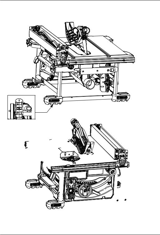
Fig. A
|
11 |
14 |
|
|
2 |
||
|
20 |
1 |
18
19
22
5
12
|
13 |
|
|
24 |
|
|
9 |
|
|
25 |
|
|
11 |
16 |
|
15 |
17 |
23
8
1
19
28
Fig. C
29
21
11
2
Fig. D
15
30
2
|
Fig. E |
17 |
Fig. F |
|
32 |
||
|
31 |
||
|
47 |
Fig. G
33
34
Fig. H
47
19
5
Fig. I
35
5
3
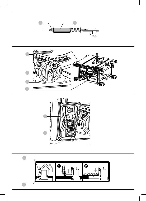
Fig. J
Fig. K
39
38
6
7
Fig. L
40
41
42
4

Fig. N

 20
20
Fig. O
|
20 |
||
|
21 |
||
|
11 |
17 |
|
|
16 |
||
|
19 |
||
|
10 |
||
|
Fig. P |
Fig. Q |
|
|
46 |
||
|
45 |
||
|
44 |
||
|
5 |
6
NOTICE: Indicates a practice not related to personal injury which, if not avoided, may result in property damage.
An estimation of the level of exposure to vibration and/or noise should also take into account the times when the tool is switched off or when it is running but not actually doing
moderate injury.
CAUTION: Indicates a potentially hazardous situation which, if not avoided, may result in minor or
serious injury.
WARNING: Indicates a potentially hazardous situation which, if not avoided, could result in death or
WARNING: The declared vibration and/or noise emission level represents the main applications of the tool. However if the tool is used for different applications, with different accessories or poorly maintained, the vibration and/or noise emission may differ. This may significantly increase the exposure level over the total working period.
DANGER: Indicates an imminently hazardous situation which, if not avoided, will result in death or serious injury.
The vibration and/or noise emission level given in this information sheet has been measured in accordance with a standardised test given in EN62841 and may be used to
compare one tool with another. It may be used for a preliminary
assessment of exposure.
The definitions below describe the level of severity for each signal word. Please read the manual and pay attention to
these symbols.
the job. This may significantly reduce the exposure level over the total working period.
Identify additional safety measures to protect the operator from the effects of vibration and/or noise such as: maintain the tool and the accessories, keep the hands warm (relevant for vibration), organisation of work patterns.
EC-Declaration of Conformity
Machinery Directive
Table Saw
DWE7485
DeWALT declares that these products described under Technical Data are in compliance with:
2006/42/EC, EN62841-1:2015+AC:2015,
EN62841 3 1:2014+AC:2015 + A11:2017.
These products also comply with Directive 2014/30/EU and 2011/65/EU. For more information, please contact DeWALT at the following address or refer to the back of the manual.
The undersigned is responsible for compilation of the technical file and makes this declaration on behalf of DeWALT.
Markus Rompel
Vice-President Engineering, PTE-Europe DeWALT, Richard-Klinger-Straße 11, D-65510, Idstein, Germany
09.08.2019
WARNING: To reduce the risk of injury, read the instruction manual.
Definitions: Safety Guidelines
English
TABLE SAW
DWE7485
Congratulations!
You have chosen a DeWALT tool. Years of experience, thorough product development and innovation make DeWALT one of the most reliable partners for professional power tool users.
Technical Data
|
DWE7485 |
DWE7485 |
DWE7485 |
||
|
(QS, GB) |
(XE) |
(LX) |
||
|
Voltage |
VDC |
230 |
220–240 |
115 |
|
Type |
1 |
1 |
1 |
|
|
Rated input power |
W |
1850 |
1850 |
1700 |
|
No load speed |
min-1 |
5800 |
5800 |
5800 |
|
Blade diameter |
mm |
210 |
210 |
210 |
|
Blade bore |
mm |
30 |
30 |
30 |
|
Blade kerf |
mm |
1.8 |
1.8 |
1.8 |
|
Blade body thickness |
mm |
1.3 |
1.3 |
1.3 |
|
Riving knife thickness |
mm |
1.6 |
1.6 |
1.6 |
|
Depth of cut at 90° |
mm |
65 |
65 |
65 |
|
Depth of bevel cut at 45° |
mm |
45 |
45 |
45 |
|
Ripping capacity |
mm |
622.3 |
622.3 |
622.3 |
|
(Right of blade) |
||||
|
Ripping capacity (Left of blade) |
mm |
318 |
318 |
318 |
|
Work surface dimensions |
mm |
485 x 485 |
485 x 485 |
485 x 485 |
|
Overall dimensions |
mm |
605 x 605 |
605 x 605 |
605 x 605 |
|
x 330 |
x 330 |
x 330 |
||
|
Weight |
kg |
22 |
22 |
22 |
Noise values and/or vibration values (triax vector sum) according to EN62841-1-2015:
|
LPA |
(emission sound pressure |
dB(A) |
90 |
90 |
91 |
|
level) |
|||||
|
LWA |
(sound power level) |
dB(A) |
107 |
107 |
108 |
|
K |
(uncertainty for the given |
dB(A) |
3 |
3 |
3 |
|
sound level) |

|
English |
||||
|
Denotes risk of electric shock. |
b ) |
Use personal protective equipment. Always wear eye |
||
|
protection. Protective equipment such as a dust mask, |
||||
|
Denotes risk of fire. |
non-skid safety shoes, hard hat or hearing protection used |
|||
|
for appropriate conditions will reduce personal injuries. |
||||
|
GENERAL POWER TOOL SAFETY WARNINGS |
c ) |
Prevent unintentional starting. Ensure the switch |
||
|
WARNING: Read all safety warnings, instructions, |
is in the off-position before connecting to power |
|||
|
source and/or battery pack, picking up or carrying |
||||
|
illustrations and specifications provided with this |
||||
|
the tool. Carrying power tools with your finger on the |
||||
|
power tool. Failure to follow all instructions listed below |
||||
|
switch or energising power tools that have the switch on |
||||
|
may result in electric shock, fire and/or serious injury. |
||||
|
invites accidents. |
||||
|
SAVE ALL WARNINGS AND INSTRUCTIONS |
||||
|
d ) |
Remove any adjusting key or wrench before turning |
|||
|
FOR FUTURE REFERENCE |
||||
|
the power tool on. A wrench or a key left attached |
||||
|
The term “power tool” in the warnings refers to your mains- |
to a rotating part of the power tool may result in |
|||
|
operated (corded) power tool or battery-operated (cordless) |
personal injury. |
|||
|
power tool. |
e ) |
Do not overreach. Keep proper footing and balance |
||
|
1) Work Area Safety |
at all times. This enables better control of the power tool |
|||
|
a ) |
Keep work area clean and well lit. Cluttered or dark |
in unexpected situations. |
||
|
f ) |
Dress properly. Do not wear loose clothing or |
|||
|
areas invite accidents. |
||||
|
b ) |
Do not operate power tools in explosive |
jewellery. Keep your hair and clothing away from |
||
|
moving parts. Loose clothes, jewellery or long hair can be |
||||
|
atmospheres, such as in the presence of flammable |
||||
|
caught in moving parts. |
||||
|
liquids, gases or dust. Power tools create sparks which |
||||
|
g ) |
If devices are provided for the connection of dust |
|||
|
may ignite the dust or fumes. |
||||
|
c ) |
Keep children and bystanders away while operating |
extraction and collection facilities, ensure these are |
||
|
connected and properly used. Use of dust collection |
||||
|
a power tool. Distractions can cause you to lose control. |
||||
|
can reduce dust-related hazards. |
||||
|
2) Electrical Safety |
||||
|
h ) |
Do not let familiarity gained from frequent use of |
|||
|
a ) |
Power tool plugs must match the outlet. Never |
|||
|
tools allow you to become complacent and ignore |
||||
|
modify the plug in any way. Do not use any adapter |
||||
|
tool safety principles. A careless action can cause severe |
||||
|
plugs with earthed (grounded) power tools. |
||||
|
injury within a fraction of a second. |
||||
|
Unmodified plugs and matching outlets will reduce risk of |
||||
|
4) Power Tool Use and Care |
||||
|
electric shock. |
||||
|
a ) |
Do not force the power tool. Use the correct power |
|||
|
b ) |
Avoid body contact with earthed or grounded |
|||
|
tool for your application. The correct power tool |
||||
|
surfaces, such as pipes, radiators, ranges and |
||||
|
will do the job better and safer at the rate for which it |
||||
|
refrigerators. There is an increased risk of electric shock if |
||||
|
was designed. |
||||
|
your body is earthed or grounded. |
||||
|
b ) |
Do not use the power tool if the switch does not turn |
|||
|
c ) |
Do not expose power tools to rain or wet conditions. |
|||
|
it on and off. Any power tool that cannot be controlled |
||||
|
Water entering a power tool will increase the risk of |
||||
|
with the switch is dangerous and must be repaired. |
||||
|
electric shock. |
||||
|
c ) |
Disconnect the plug from the power source and/ |
|||
|
d ) |
Do not abuse the cord. Never use the cord for |
|||
|
or remove the battery pack, if detachable, from |
||||
|
carrying, pulling or unplugging the power tool. Keep |
||||
|
the power tool before making any adjustments, |
||||
|
cord away from heat, oil, sharp edges or moving |
||||
|
changing accessories, or storing power tools. Such |
||||
|
parts. Damaged or entangled cords increase the risk of |
||||
|
preventive safety measures reduce the risk of starting the |
||||
|
electric shock. |
||||
|
power tool accidentally. |
||||
|
e ) |
When operating a power tool outdoors, use an |
|||
|
d ) |
Store idle power tools out of the reach of children |
|||
|
extension cord suitable for outdoor use. Use of a cord |
||||
|
and do not allow persons unfamiliar with the power |
||||
|
suitable for outdoor use reduces the risk of electric shock. |
||||
|
tool or these instructions to operate the power tool. |
||||
|
f ) |
If operating a power tool in a damp location is |
|||
|
Power tools are dangerous in the hands of untrained users. |
||||
|
unavoidable, use a residual current device (RCD) |
||||
|
e ) |
Maintain power tools and accessories. Check for |
|||
|
protected supply. Use of an RCD reduces the risk of |
||||
|
misalignment or binding of moving parts, breakage |
||||
|
electric shock. |
||||
|
of parts and any other condition that may affect the |
||||
|
3) Personal Safety |
||||
|
power tool’s operation. If damaged, have the power |
||||
|
a ) |
Stay alert, watch what you are doing and use |
|||
|
tool repaired before use. Many accidents are caused by |
||||
|
common sense when operating a power tool. Do not |
poorly maintained power tools. |
|||
|
use a power tool while you are tired or under the |
f ) |
Keep cutting tools sharp and clean. Properly |
||
|
influence of drugs, alcohol or medication. A moment |
||||
|
maintained cutting tools with sharp cutting edges are less |
|
of inattention while operating power tools may result in |
likely to bind and are easier to control. |
|
|
serious personal injury. |
||
7

English
g ) Use the power tool, accessories and tool bits etc. in accordance with these instructions, taking into account the working conditions and the work to be
performed. Use of the power tool for operations different from those intended could result in a hazardous situation.
h ) Keep handles and grasping surfaces dry, clean and free from oil and grease. Slippery handles and grasping surfaces do not allow for safe handling and control of the tool in unexpected situations.
5)Service
a ) Have your power tool serviced by a qualified repair person using only identical replacement parts. This
will ensure that the safety of the power tool is maintained.
Safety Instructions for Table Saws
1)Guarding Related Warnings
a ) Keep guards in place. Guards must be in working order and be properly mounted. A guard that is loose, damaged, or is not functioning correctly must be repaired or replaced.
b ) Always use saw blade guard, riving knife for every through–cutting operation. For through-cutting operations where the saw blade cuts completely through the thickness of the workpiece, the guard and other safety devices help reduce the risk of injury.
c ) Immediately reattach the guarding system after completing an operation (such as rabbeting or resawing cuts) which requires removal of the guard or riving knife. The guard and riving knife help to reduce the risk of injury.
d ) Make sure the saw blade is not contacting the guard, riving knife or the workpiece before the switch is turned on. Inadvertent contact of these items with the saw blade could cause a hazardous condition.
e ) Adjust the riving knife as described in this instruction manual. Incorrect spacing, positioning and alignment can make the riving knife ineffective in reducing the likelihood of kickback.
f ) For the riving knife to work, they must be engaged in the workpiece. The riving knife is ineffective when cutting workpieces that are too short to be engaged with the riving knife. Under these conditions a kickback cannot be prevented by the riving knife .
g ) Use the appropriate saw blade for the riving knife.
For the riving knife to function properly, the saw blade diameter must match the appropriate riving knife and the body of the saw blade must be thinner than the thickness of the riving knife and the cutting width of the saw blade must be wider than the thickness of the riving knife.
2)Cutting Procedures Warnings
|
a ) |
DANGER: Never place your fingers or hands in |
|
the vicinity or in line with the saw blade. |
|
|
A moment of inattention or a slip could direct your hand |
|
|
towards the saw blade and result in serious |
|
|
personal injury. |
b ) Feed the workpiece into the saw blade only against the direction of rotation. Feeding the workpiece in the same direction that the saw blade is rotating above the table may result in the workpiece, and your hand, being pulled into the saw blade.
c ) Never use the mitre gauge to feed the workpiece when ripping and do not use the rip fence as a length stop when cross cutting with the mitre gauge.
Guiding the workpiece with the rip fence and the mitre gauge at the same time increases the likelihood of saw blade binding and kickback.
d ) When ripping, always apply the workpiece feeding force between the fence and the saw blade. Use a push stick when the distance between the fence and the saw blade is less than 150 mm, and use a push block when this distance is less than 50 mm. “Work helping” devices will keep your hand at a safe distance from the saw blade.
e ) Use only the push stick provided by the manufacturer or constructed in accordance with the instructions. This push stick provides sufficient distance of the hand from the saw blade.
f ) Never use a damaged or cut push stick. A damaged push stick may break causing your hand to slip into the saw blade.
g ) Do not perform any operation “freehand.” Always use either the rip fence or the mitre gauge to position and guide the workpiece. “Freehand” means using your hands to support or guide the workpiece, in lieu of a rip fence or mitre gauge. Freehand sawing leads to misalignment, binding and kickback.
h ) Never reach around or over a rotating saw blade.
Reaching for a workpiece may lead to accidental contact with the moving saw blade.
i ) Provide auxiliary workpiece support to the rear and/or sides of the saw table for long and/or wide workpieces to keep them level. A long and/or wide workpiece has a tendency to pivot on the table’s edge, causing loss of control, saw blade binding and kickback.
j ) Feed workpiece at an even pace. Do not bend or twist the workpiece. If jamming occurs, turn the tool off immediately, unplug the tool then clear the jam. Jamming the saw blade by the workpiece can cause kickback or stall the motor.
k ) Do not remove pieces of cut-off material while the saw is running. The material may become trapped between the fence or inside the saw blade guard and the saw blade pulling your fingers into the saw blade. Turn the saw off and wait until the saw blade stops before removing material.
l ) Use an auxiliary fence in contact with the table top when ripping workpieces less than 2 mm thick. A thin workpiece may wedge under the rip fence and create a kickback.
8
![]()
English
3) Kickback Causes and Related Warnings
Kickback is a sudden reaction of the workpiece due to a pinched, jammed saw blade or misaligned line of cut in the workpiece with respect to the saw blade or when a part of the workpiece binds between the saw blade and the rip fence or other fixed object.
Most frequently during kickback, the workpiece is lifted from the table by the rear portion of the saw blade and is propelled towards the operator. Kickback is the result of saw misuse and/or incorrect operating procedures or conditions and can be avoided by taking proper precautions as given below.
a ) Never stand directly in line with the saw blade.
Always position your body on the same side of the saw blade as the fence. Kickback may propel the workpiece at high velocity towards anyone standing in front and in line with the saw blade.
b ) Never reach over or in back of the saw blade to pull or to support the workpiece. Accidental contact with the saw blade may occur or kickback may drag your fingers into the saw blade.
c ) Never hold and press the workpiece that is being cut off against the rotating saw blade. Pressing the workpiece being cut off against the saw blade will create a binding condition and kickback.
d ) Align the fence to be parallel with the saw blade. A misaligned fence will pinch the workpiece against the saw blade and create kickback.
e ) Use a featherboard to guide the workpiece against the table and fence when making non-through cuts such as rabbeting or resawing cuts. A featherboard helps to control the workpiece in the event of a kickback.
f ) Use extra caution when making a cut into blind areas of assembled workpieces. The protruding saw blade may cut objects that can cause kickback.
g ) Support large panels to minimise the risk of saw blade pinching and kickback. Large panels tend to sag under their own weight. Support(s) must be placed under all portions of the panel overhanging the table top.
h ) Use extra caution when cutting a workpiece that is twisted, knotted, warped or does not have a straight edge to guide it with a mitre gauge or along the fence. A warped, knotted, or twisted workpiece is unstable and causes misalignment of the kerf with the saw blade, binding and kickback.
i ) Never cut more than one workpiece, stacked vertically or horizontally. The saw blade could pick up one or more pieces and cause kickback.
j ) When restarting the saw with the saw blade in the workpiece, centre the saw blade in the kerf so that the saw teeth are not engaged in the material. If the saw blade binds, it may lift up the workpiece and cause kickback when the saw is restarted.
k ) Keep saw blades clean, sharp, and with sufficient set. Never use warped saw blades or saw blades with cracked or broken teeth. Sharp and properly set saw blades minimise binding, stalling and kickback.
4)Table Saw Operating Procedure Warnings
a ) Turn off the table saw and disconnect the power cord when removing the table insert, changing the saw blade or making adjustments to the riving knife, or saw blade guard, and when the machine is left unattended. Precautionary measures will avoid accidents.
b ) Never leave the table saw running unattended.
Turn it off and don’t leave the tool until it comes to a complete stop. An unattended running saw is an uncontrolled hazard.
c ) Locate the table saw in a well-lit and level area where you can maintain good footing and balance. It should be installed in an area that provides enough room to easily handle the size of your workpiece. Cramped, dark areas, and uneven slippery floors invite accidents.
d ) Frequently clean and remove sawdust from under the saw table and/or the dust collection device.
Accumulated sawdust is combustible and may self-ignite. e ) The table saw must be secured. A table saw that is not
properly secured may move or tip over.
f ) Remove tools, wood scraps, etc. from the table before the table saw is turned on. Distraction or a potential jam can be dangerous.
g ) Always use saw blades with correct size and shape (diamond versus round) of arbour holes. Saw blades that do not match the mounting hardware of the saw will run off-centre, causing loss of control.
h ) Never use damaged or incorrect saw blade mounting means such as flanges, saw blade washers, bolts or nuts. These mounting means were specially designed for your saw, for safe operation and optimum performance.
i ) Never stand on the table saw, do not use it as a stepping stool. Serious injury could occur if the tool is tipped or if the cutting tool is accidentally contacted.
j ) Make sure that the saw blade is installed to rotate in the proper direction. Do not use grinding wheels, wire brushes, or abrasive wheels on a table saw.
Improper saw blade installation or use of accessories not recommended may cause serious injury.
Additional Safety Rules for Saw Benches
WARNING: Cutting plastics, sap coated wood, and other materials may cause melted material to accumulate on the blade tips and the body of the saw blade, increasing the risk of blade overheating and binding while cutting.
•Make sure that the blade rotates in the correct direction and that the teeth are pointing to the front of the saw bench.
•Be sure all clamp handles are tight before starting any operation.
•Be sure all blade and flanges are clean and the larger face of the clamp washer is against the blade. Tighten the arbor nut securely.
9

English
•Make sure that the riving knife is adjusted to the correct distance from the blade — maximum 8 mm.
•Never operate the saw without the upper and lower guards in place.
•Do not apply lubricants to the blade when it is running.
•Always keep the push stick in its store place when not in use.
•Do not use the guard for handling or transportation.
•Do not exert side pressure on the saw blade.
•Never cut light alloy. The machine is not designed for this application.
•Do not use abrasive disc or diamond cutting wheels.
•Rabbeting, slotting or grooving is not allowed.
•In case of machine failure, immediately switch the machine off and remove from the power source. Report the failure and mark the machine in suitable form which prevents that other persons use the defective machine.
•When the saw blade is blocked due to abnormal feed force during cutting, ALWAYS switch the machine off and remove from the power source. Remove the workpiece and ensure that the saw blade runs free. Turn the machine on and start a new cutting operation with reduced feed force.
•NEVER attempt to cut a stack of loose pieces of material which could cause loss of control or kickback. Support all materials securely.
•Take care that the blade guard is properly positioned. When sawing, it must always face against the workpiece.
Saw Blades
•Do not use saw blades that do not conform to the dimensions stated in the Technical Data. Do not use any spacers to make a blade fit onto the spindle. Use only the blades specified in this manual, complying with EN847-1, if intended for wood and similar materials.
•The maximunm speed of the saw blade shall always be greater than or at least equal to the speed marked on the rating plate of the tool.
•The saw blade diameter must be in accordance with the markings on rating plate of the tool.
•Consider applying specially designed noise-reduction blades.
•Do not use high steel (HS) saw blades.
•Do not use cracked or damaged saw blades.
•Ensure that the chosen saw blade is suitable for the material to be cut.
•Always wear gloves for handling saw blades and rough material. Saw blades should be carried in a holder wherever practicable.
Residual risks
The following risks are inherent to the use of saws:
•injuries caused by touching the rotating parts
In spite of the application of the relevant safety regulations and the implementation of safety devices, certain residual risks cannot be avoided. These are:
•Impairment of hearing.
•Risk of accidents caused by the uncovered parts of the rotating saw blade.
•Risk of injury when changing the saw blade with unprotected hands.
•Risk of squeezing fingers when opening the guards.
•Health hazards caused by breathing dust developed when sawing wood, especially oak, beech and MDF.
The following factors are of influence to noise production:
•the material to be cut
•the type of saw blade
•the feed force
•machine maintenance
The following factors are of influence to dust exposure:
•worn saw blade
•dust extractor with air velocity less than 20 m/s
•workpiece not exactly guided
Electrical Safety
The electric motor has been designed for one voltage only. Always check that the power supply corresponds to the voltage on the rating plate.
Your DeWALT tool is double insulated in accordance with EN62841; therefore no earth wire is required.
If the supply cord is damaged, it must be replaced only by DeWALT or an authorised service organisation.
NOTE: This device is intended for the connection to a power supply system with maximum permissible system impedance Zmax of 0.25 Ω at the interface point (power service box)
of user’s supply. The user has to ensure that this device is connected only to a power system which fulfills the requirement above. If necessary, the user can ask the public power supply company for the system impedance at the interface point.
Mains Plug Replacement (U.K. & Ireland Only)
If a new mains plug needs to be fitted:
•Safely dispose of the old plug.
•Connect the brown lead to the live terminal in the plug.
•Connect the blue lead to the neutral terminal.WARNING: No connection is to be made to the
earth terminal.
Follow the fitting instructions supplied with good quality plugs. Recommended fuse: 13 A.
Using an Extension Cable
If an extension cable is required, use an approved 3–core extension cable suitable for the power input of this tool (see Technical Data).The minimum conductor size is 1.5 mm2; the maximum length is 30 m.
When using a cable reel, always unwind the cable completely.
10
English
Package Contents
The package contains:
1Partly assembled machine
1Rip fence assembly
1Mitre fence
1Saw blade
1Upper blade guard assembly
1Throat plate
2Blade wrenches
1 Dust extraction adapter
1 Instruction manual
•Check for damage to the tool, parts or accessories which may have occurred during transport.
•Take the time to thoroughly read and understand this manual prior to operation.
Markings on Tool
The following pictograms are shown on the tool:
Read instruction manual before use.
Wear ear protection.
Wear eye protection.
Wear face mask.
Keep hands away from cutting area and the blade.
 Carrying point.
Date Code Position (Fig. A)
The date code 25 , which also includes the year of manufacture, is printed into the housing.
Example:
2019 XX XX
Year of Manufacture
Description (Fig. A, C)
WARNING: Never modify the power tool or any part of it. Damage or personal injury could result.
|
1 |
Table |
9 |
Mounting holes |
|
2 |
Blade |
10 |
Mitre gauge |
|
3 |
Rip scale indicator |
11 |
Blade guard assembly |
|
4 |
Fine adjust knob |
12 |
Carry handle |
|
5 |
Rail lock lever |
13 |
Dust collection port |
|
6 |
Blade height adjustment |
14 |
Guard dust collection port |
|
wheel |
15 |
Throat plate |
|
|
7 |
Bevel lock lever |
16 |
Rip fence |
|
8 |
ON/OFF assembly |
17 |
Rip fence latch |
|
18 |
Narrow ripping fence/ |
21 |
Riving knife (non-through |
|
support extension |
sawing) (Fig. C) |
||
|
19 |
Blade wrenches (stored |
22 |
Mitre gauge storage |
|
position) |
23 |
Cable holder |
|
|
20 |
Push stick (stored position) |
24 |
DE7400 brackets mounting |
|
holes |
Intended Use
Your table saw has been designed for professional ripping, cross-cutting, mitreing and bevelling with various materials as wood analogous materials and plastic.
DO NOT use under wet conditions or in the presence of flammable liquids or gases.
This table saw is a professional power tool.
DO NOT let children come into contact with the tool. Supervision is required when inexperienced operators use this tool.
•Young children and the infirm. This appliance is not intended for use by young children or infirm persons without supervision.
•This product is not intended for use by persons (including children) suffering from diminished physical, sensory or mental abilities; lack of experience, knowledge or skills unless they are supervised by a person responsible for their safety. Children should never be left alone with this product.
ASSEMBLY AND ADJUSTMENTS
WARNING: To reduce the risk of serious personal injury, turn tool off and disconnect tool from power source before making any adjustments or removing/ installing attachments or accessories. An accidental start-up can cause injury.
Unpacking
•Remove the saw from the packaging material carefully.
•The machine is fully assembled except for the rip fence, mitre gauge, dust adapter and blade guard assembly.
•Finalise the assembly following the instructions as described below.
Mounting the Saw Blade (Fig. A, B)
WARNING: To reduce the risk of serious personal injury, turn tool off and disconnect tool from power source before making any adjustments or removing/ installing attachments or accessories. An accidental start-up can cause injury.
WARNING: To reduce the risk of injury, wear gloves when handling the saw blade.
WARNING: The teeth of a new blade are very sharp and can be dangerous.
WARNING: The saw blade MUST be replaced as described in this section. ONLY use saw blades as specified under Technical Data. We suggest DT99565. NEVER fit other saw blades.
NOTE: This tool has blade installed from factory.
11

WARNING: To reduce the risk of serious personal injury, DO NOT operate saw if blade assembly is not securely clamped in place.
WARNING: Before connecting the table saw to the power source or operating the saw, always inspect the blade guard assembly for proper alignment and clearance with saw blade. Check alignment after each change of bevel angle.
WARNING: Always check the rip fence pointer and the blade guard assembly after having changed the blade.
WARNING: Never use the machine without the throat plate. Immediately replace the throatplate when worn or damaged.
English
1. Raise the saw blade arbour to its maximum height by turning the blade height adjustment wheel 6 clockwise.
2. Remove the throat plate 15 . Refer to Mounting the Throat Plate.
3. Using wrenches 19 , loosen and remove the arbour nut 26 and clamp washer 27 from the saw arbour by turning anti–clockwise.
4. Place the saw blade on to the arbour 28 making sure the teeth of the blade 2 point down at the front of the table. Assemble the washers and arbour nut to the spindle and tighten arbour nut 26 as far as possible by hand, making sure that the saw blade is against the inner washer and the outer clamp washer 27 is against the blade. Ensure the largest diameter of the flange is against the blade. Ensure the spindle and washers are free from dust and debris.
5. To keep the spindle from rotating when tightening the arbour nut, use the open end of the blade wrench 19 to secure the spindle.
6. Using the closed end of the blade wrench, tighten the arbour nut 26 firmly by turning it clockwise.
7. Replace the throat plate.
Mounting/Removing the Blade Guard Assembly/Riving Knife (Fig. A, C)
WARNING: Use the guard assembly for all through cutting.
1. Raise the saw blade arbour to its maximum height.
2. Loosen the riving knife lock knob 29 (minimum of three turns).
3. To disengage riving knife lock pin, pull lock knob as indicated by the black arrows on the knob.
4. While pulling the lock knob, lift the riving knife out of the clamp. Then slide the blade guard assembly 11 into the clamp until it bottoms out.
NOTE: Do not install both blade guard assembly and riving knife into the clamp at the same time.
5. Release the lock knob to engage the lock pin. Give the blade guard a slight pull upwards to ensure pin is engaged.
6. Tighten the riving knife lock knob.
NOTE: Follow the same procedure for the riving knife.
When properly aligned, the riving knife 21 will be in line with the blade at both table top level, and at the top of the blade. Using a straight edge, ensure that the blade 2 is aligned with the riving knife 21 . With power disconnected, operate the blade tilt and height adjustments through the extremes of
travel and insure the blade guard assembly clears the blade in all operations.
WARNING: Correct mounting and alignment of the blade guard assembly is essential to safe operation!
Mounting the Throat Plate (Fig. D)
1. Align the throat plate 15 as shown in Figure D, and insert the tabs on the back of the throat plate into the holes on the back of the table opening.
2. Turn the locking screw 30 with a screwdriver clockwise 90° to lock the table insert in place.
3. The throat plate includes four adjustment screws which raise or lower the throat plate. When properly adjusted, the front of the throat plate should be flush or slightly below the surface of the table top and secured in place. The rear of the
throat plate should be flush or slightly above the table top.
Removing the Throat Plate
1.Remove the throat plate 15 by turning the locking screw 30 with a screwdriver 90˚ anti-clockwise
2.Pull throat plate up and forward to expose the inside of the saw. DO NOT operate the saw without the throat plate.
Fitting the Rip Fence (Fig. E)
The rip fence can be installed in two positions on the right (Position 1 47 for 0 mm to 510 mm ripping, and Position 2 47 for 100 mm to 610 mm ripping.) and one position on the left of your table saw.
1.Unlock the rip fence latches 17 .
2.Holding the fence at an angle, align the locator pins 47 (front and back) on the fence rails with the fence head slots 31 .
3.Slide the head slots onto the pins and rotate the fence down until it rests on the rails.
4.Lock the fence in place by closing the front and back latches 17 onto the rails.
Fixing to Workbench (Fig. A)
•The machine frame between the feet on each side is provided with two holes 9 which allow fixing on a workbench. Use the holes diagonally.
•To improve the handling, fix the machine onto a piece of plywood a minimum of 15 mm thick.
When in use, the plywood sheet can be clamped to the workbench. This allows easier transportation of the machine, by releasing the clamps.
Holes 24 are also provided under under the saw feet for mounting to DE7400 brackets.
12

ADJUSTMENTS Blade Adjustment
Blade Alignment (Parallel to Mitre Slot) (Fig. F)
WARNING: Cut Hazard. Check the blade at 0˚ and 45˚ to make sure blade does not hit the throat plate, causing personal injury.
If the blade appears to be out of alignment with the mitre slot on the table top, it will require calibration for alignment. To realign the blade and mitre slot, use the following procedure:
WARNING: To reduce the risk of serious personal injury, turn tool off and disconnect tool from power source before making any adjustments or removing/ installing attachments or accessories. An accidental start-up can cause injury.
1. Using a 5 mm hex wrench, loosen rear pivot bracket fasteners 32 , located on the underside of the table, just enough to allow the bracket to move side-to-side.
2. Adjust the bracket until the blade is parallel to the mitre gauge slot.
3. Tighten the rear pivot bracket fasteners to 12.5–13.6 Nm.
Blade Height Adjustment (Fig. A)
The blade can be raised and lowered by turning the blade height adjustment wheel 6 .
Make sure the top three teeth of the blade are just breaking through the upper surface of the workpiece when sawing. This will ensure that the maximum number of teeth are removing material at any given time, thus giving optimum performance.
Aligning Guard Assembly to Blade (Fig. G)
1. Remove the throat plate. Refer to Removing Throat Plate under Assembly and Adjustments.
2. Raise the blade to full depth of cut and 0° bevel angle.
3. Locate the three small set screws 33 . These screws will be used to adjust the riving knife position.
4. Lay a straight edge on the table against two blade tips. The riving knife should not touch the straight edge.
5. If adjustment is needed, loosen the two larger lock screws 34 .
English
6.Use the small set screws 33 to adjust the riving knife position. Lay the straight edge on the opposite side of the blade and repeat adjustments as needed.
7.Lightly tighten the two larger lock screws 34 .
8.Place a square flat against the riving knife to verify the riving knife is vertical and in-line with the blade.
9.If needed, use the set screws to bring the riving knife vertical with the square.
10.Repeat step 4 to verify position of riving knife. Repeat 5 through 9 if necessary.
11.Fully tighten the two larger lock screws 34 .
Parallel Adjustment (Fig. A, H, I)
For optimum performance, the blade must be parallel to the rip fence. This adjustment has been made at the factory. To re-adjust:
Position 1 Fence Alignment
1.Install the fence in position 1 and unlock the rail lock
lever 5 . Locate both locator pins 47 that support the fence on the front and rear rails.
2.Loosen the rear locator pin screw and adjust the allignment of the fence in the groove until the fence face is parallel to the blade. Make sure you measure from the fence face to the front and back of the blade to ensure alignment.
3.Tighten the locator screw and repeat on the left side of the blade.
4.Check rip scale pointer adjustment (Fig. I).
Position 2 Fence Alignment (Fig. H)
1.To align position 2 fence locator pins 47 , ensure position 1 pins have been aligned, refer to Position 1 Fence Alignment.
2.Loosen the position 2 pins, then using the holes on the blade wrench 19 as a guide for positioning, align the pins (Fig. H).
3.Tighten the locator pins (front and rear).
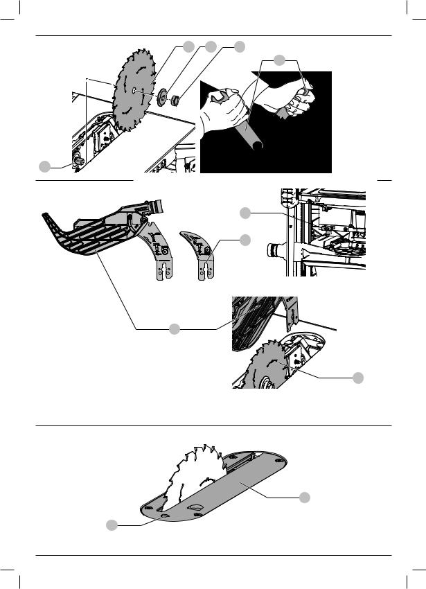
Adjusting the Rip Scale (Fig. H, I)
1.Unlock the rail lock lever 5 .
2.Set the blade at 0° bevel and move the fence in until it touches the blade.
3.Lock the rail lock lever.
4.Loosen the rip scale indicator screws 35 and set the rip scale indicator to read zero (O). Retighten the rip scale indicator screws. The yellow rip scale (top) reads correctly only when the fence is mounted on the right side of the blade and is in position 1 47 (for 0 mm to 510 mm ripping) not the 610 mm rip position. The white scale (bottom) reads correctly only when the fence is mounted on the right side of the blade and in position 2 47 (for 100 mm to 610 mm ripping).
The rip scale reads correctly only when the fence is mounted to the right of the blade.
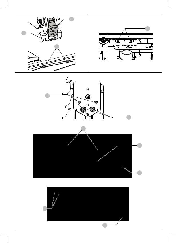
Rail Lock Adjustment (Fig. I, J)
The rail lock has been factory-set. If you need to re-adjust, proceed as follows:
1.Lock the rail lock lever 5 .
2.On the underside of the saw, loosen the jam nut 36 .
3.Tighten the hex rod 37 until the spring on the locking system is compressed creating the desired tension on the rail lock lever. Retighten the jam nut against the hex rod.
4.Flip the saw over and check that the fence does not move when the lock lever is engaged. If the fence is still loose, tighten the spring further.
13

English
Bevel Stop And Pointer Adjustment (Fig. K)
1.Raise the blade fully by rotating the blade height adjustment wheel 6 clockwise until it stops.
2.Unlock the bevel lock lever 7 by pushing it up and to the right. Loosen the bevel stop screw 38 .
3.Place a square flat against the table top and against the blade between teeth. Ensure the bevel lock lever is in its unlocked, or up, position.
4.Using the bevel lock lever, adjust the bevel angle until it is flat against the square.
5.Tighten the bevel lock lever by pushing it down.
6.Turn the bevel stop screw 38 to rotate the cam until it firmly contacts the bearing block. Tighten the bevel stop screw.
7.Check the bevel angle scale. If the pointer does not read 0°, loosen pointer screw 39 and move the pointer so it reads correctly. Retighten the pointer screw.
8.Repeat at 45°, but do not adjust pointer.
Mitre Gauge Adjustment (Fig. A)
To adjust mitre gauge 10 loosen knob, set to desired angle and tighten knob.
Body and Hand Position
Proper positioning of your body and hands when operating the table saw will make cutting easier, more accurate and safer.
WARNING:
•Never place your hands near the cutting area.
•Place your hands no closer than 150 mm from the blade.
•Do not cross your hands.
•Keep both feet firmly on the floor and maintain proper balance.
Prior to Operation
WARNING:
•Install the appropriate saw blade. Do not use excessively worn blades.The maximum rotation speed of the tool must not exceed that of the saw blade.
•Do not attempt to cut excessively small pieces.
•Allow the blade to cut freely. Do not force.
•Allow the motor to reach full speed before cutting.
OPERATION
Instructions for Use
WARNING: Always observe the safety instructions and applicable regulations.
WARNING: To reduce the risk of serious personal injury, turn tool off and disconnect tool from power source before making any adjustments or removing/ installing attachments or accessories. An accidental start-up can cause injury.
To reduce effects of increased vibration, make sure the environment is not too cold, the machine and accessory are well maintained and the workpiece size is suitable for this machine.
WARNING:
•Always observe the safety instructions and applicable regulations.
•Ensure the machine is placed to satisfy ergonomic conditions in terms of table height and stability. The machine site shall be chosen so that the operator has a good overview and enough free surrounding space around the machine that allow handling of the workpiece without any restrictions.
•Install the appropriate saw blade. Do not use excessively worn blades. The maximum rotation speed of the tool must not exceed that of the saw blade.
•Do not attempt to cut excessively small pieces.
•Allow the blade to cut freely. Do not force.
•Allow the motor to reach full speed before cutting.
•Make sure all locking knobs and clamp handles are tight.
•Never place either hand in the blade area when the saw is connected to the electrical power source.
•Never use your saw for freehand cuts!
•Do not saw warped, bowed or cupped workpieces. There must be at least one straight, smooth side to go against the rip fence or mitre fence.
•Always support long workpieces to prevent kickback.
•Do not remove any cut-offs from the blade area while the blade is running.
Switching On and Off (Fig. A, L)
The on/off assembly 8 of your saw bench offers multiple advantages:
•No-volt release function: should the power be shut off for any reason, the switch has to be deliberately reactivated.
•To switch the machine on, press the green start button 40 .
•To switch the machine off, press the red stop button 41 .
Lock Off Feature Instructions
A cover above the switch folds down for insertion of a padlock to lock the saw off. A padlock with a maximum diameter of 6.35 mm and minimum clearance of 76.2 mm is recommended.
Rip Fence Operation (Fig. A, M)
Rail Lock Lever
The rail lock lever 5 locks the fence in place preventing movement during cutting. To lock the rail lever, push it down and toward the rear of the saw. To unlock, pull it up and toward the front of the saw.
NOTE: When ripping, always lock the rail lock lever.
Work Support Extension /Narrow Ripping Fence
Your table saw is equipped with a work support extension to support work that extends beyond the saw table.
14
English
To use the narrow ripping fence in the work support position, rotate it from its stored position as shown in Figure M, and slide the pins into the lower sets of slots 42 on both ends of the fence.
To use the narrow ripping fence in the narrow ripping position, snap the pins into the upper sets of slots 43 on both ends of the fence. This feature will allow 51 mm of extra clearance to the blade. Refer to Figure M.
NOTE: Retract the work support extension or adjust to narrow rip fence position whenever working over the table.
Fine Adjustment Knob
The fine adjustment knob 4 allows smaller adjustments when setting the fence. Before adjusting, be sure the rail lock lever is in its up or unlocked, position.
Rip Scale Pointer
The rip scale pointer will need to be adjusted for proper performance of the rip fence if the user switches between thick and thin kerf blades. The rip scale pointer only reads correctly for position 1 (0 mm to 510 mm), however for position 1 with narrow rip fence in use add 52 mm. See Adjusting the Rip Scale under Assembly and Adjustments.
Basic Saw Cuts
Ripping (Fig. A, N)
WARNING: Sharp edges.
1.Set the blade to 0°.
2.Lock the rip fence latch 17 (Fig. A).
3.Raise the blade until it is about 3 mm higher than the top of the workpiece.
4.Adjust the position of the fence, refer to Rip
Fence Operation.
5.Hold the workpiece flat on the table and against the fence. Keep the workpiece away from the blade.
6.Keep both hands away from the path of the blade.
7.Switch the machine on and allow the blade to reach full speed.
8.Slowly feed the workpiece underneath the guard, keeping it firmly pressed against the rip fence. Allow the teeth to cut, and do not force the workpiece through the blade. The blade speed should be kept constant.
9.Always use a push stick 20 when working close to the blade (Fig. N).
10.After completing the cut, switch the machine off, allow the blade to stop and remove the workpiece.
WARNING:
•Never push or hold the «free» or cut-off-side of the workpiece.
•Do not cut excessively small workpieces.
•Always use a push stick when ripping small workpieces.
Bevel Cuts (Fig. A)
WARNING: Avoid bevel ripping on the beveling (left) side of the blade.
1.Set the required bevel angle, by rotating lever 7 by pushing it up and to the right.
2.Set to desired angle, rotate lever by pushing down and to the left to lock in place.
3.Proceed as for ripping.
Cross-Cutting and Bevel Crosscutting
1.Remove the rip fence and install the mitre gauge in the slot.
2.Lock the mitre gauge at 0°.
3.Proceed as for ripping.
Mitre Cuts (Fig. A)
1. Set the mitre gauge 10 to the required angle.
NOTE: Always hold the workpiece tightly against the face of the mitre gauge.
2. Proceed as for ripping.
Compound Mitre
This cut is a combination of a mitre and a bevel cut. Set the bevel to the angle required and proceed as for a cross-cut mitre.
Support for Long Pieces
•Always support long pieces.
•Support long workpieces using any convenient means such as saw-horses or similar devices to keep the ends from dropping.
Dust Extraction (Fig. A)
Dust from materials such as lead-containing coatings and some wood types, can be harmful to one’s health. Breathing-in the dust can cause allergic reactions and/or lead to respiratory infections of the user or bystanders. Certain dust, such as oak or beech dust, is considered carcinogenic, especially in connection with woodtreatment additives.
Observe the relevant regulations in your country for the materials to be worked.
The vacuum cleaner must be suitable for the material being worked.
When vacuuming dry dust that is especially detrimental to health or carcinogenic, use dust class M vacuum cleaner.
The machine is provided with a dust collection port 13 at the rear of the machine suitable for use with dust extraction equipment featuring 57/65 mm nozzles. Supplied with the machine is a reducer port for use of dust extraction nozzles of 34–40 mm diameter.
The blade guard assembly also features a dust collection port 14 for 35 mm nozzles and AirLock system.
•During all operations, connect a dust extraction device designed in accordance with the relevant regulations regarding dust emission.
15
MAINTENANCE
Your power tool has been designed to operate over a long period of time with a minimum of maintenance. Continuous satisfactory operation depends upon proper tool care and regular cleaning.
WARNING: To reduce the risk of serious personal injury, turn tool off and disconnect tool from power source before making any adjustments or removing/ installing attachments or accessories. An accidental start-up can cause injury.
16
English
•Ensure that the dust extraction hose in use is suitable for the application and material being cut. Ensure proper hose management.
•A splitter accessory is available to connect both ports to a single dust extractor.
•Be aware that man-made materials such as chipboard or MDF produce more dust particles during cutting than natural timber.
Storage (Fig. A, O)
1.Attach push stick 20 to fence.
2.Remove the blade guard assembly 11 . Refer to Mounting/ Removing the Blade Guard Assembly/Riving Knife. Place blade guard assembly into holder as shown, then turn lock 1/4 turn to lock in place.
3.Slide closed end of blade wrenches 19 into catch then secure in place with wing nut.
4.Insert guide bar of mitre guage 10 into pocket until it bottoms out.
5.Remove the non-through sawing riving knife 21 . Refer to
Mounting/Removing the Blade Guard Assembly/Riving Knife. Place the non-through sawing riving knife into the holder as shown, then turn lock 1/4 turn to lock in place. The non-through sawing riving knife can also be installed and stored in its regular usage position.
6.To store fence 16 , snap work support in stored position. Remove fence from rails. Reattach fence upside down on left side of saw. Pivot fence lock latches to secure.
7.Turn the handwheel 6 in anticlockwise direction until the teeth of the saw blade are positioned below the saw table 1 .
8.Wind the mains cable around the cable holder 23 .
Transporting (Fig. A)
•Turn the tool off and disconnect from power supply.
•Wind the mains cable around the cable holder 23 .
•Remove all accessories that cannot be mounted firmly to the power tool.
•Retract the work support extension.
•Always carry the machine using the carry handles 12 .
WARNING: Always transport the machine with the upper blade guard fitted.
The motor and bearings require no additional lubrication. If raising and lowering the blade becomes difficult, clean and grease the height adjustment screws:
1.Unplug the saw from power source.
2.Turn the saw on its side.
3.Clean and lubricate the height adjustment screw threads 44 on the underside of this saw as shown in Figure P. Use general purpose grease.
Cleaning (Fig. A, Q)
WARNING: Blow dirt and dust out of the main housing with dry air as often as dirt is seen collecting in and around the air vents. Wear approved eye protection and approved dust mask when performing this procedure.
WARNING: Never use solvents or other harsh chemicals for cleaning the non-metallic parts of the tool. These chemicals may weaken the materials used in these parts. Use a cloth dampened only with water and mild soap. Never let any liquid get inside the tool; never immerse any part of the tool into a liquid.
WARNING: To reduce the risk of injury, regularly clean the table top and ventilation slots.
WARNING: To reduce the risk of injury, regularly clean the dust collection system.
WARNING: To reduce the risk of serious personal injury, do not use the saw without reattaching the dust access door.
The blade guard assembly 11 and throat plate must be placed in position before operating the saw.
Before use, carefully inspect upper and lower blade guards as well as the dust extraction tube to determine that it will operate properly. Ensure that chips, dust or work piece particles cannot lead to blockage of one of the functions.
In case workpiece fragments are jammed between saw blade and guards, disconnect the machine from the power supply and follow the instructions given in section Mounting the Saw Blade. Remove the jammed parts and reassemble the saw blade.
Keep the ventilation slots clear and regularly clean the housing with a soft cloth.
Regularly clean the dust collection system:
1.Turn the saw on its side, so the bottom, open part of the unit is accessible.
2.Open the dust access door 45 shown in Figure Q loosening the two screws 46 and detaching the door. Clean out
the excess dust, then reattach the door securing it with the screws.
English
Optional Accessories
WARNING: Since accessories, other than those offered by DeWALT, have not been tested with this product, use of such accessories with this tool could be hazardous.
To reduce the risk of injury, only DeWALT recommended accessories should be used with this product.
Consult your dealer for further information on the appropriate accessories.
Replace blade guard when worn. Contact your local DeWALT service centre for details on a blade guard replacment.
SAW BLADES: ALWAYS USE 210 mm noise reduced saw blades with 30 mm arbour holes. Blade speed rating must be at least 6000 RPM. Never use a smaller diameter blade. It will not be guarded properly.
BLADE DESCRIPTIONS
|
Application |
Diameter |
Teeth |
|
Construction Saw Blades (fast rip) |
||
|
General Purpose |
210 mm |
24 |
|
Fine Crosscuts |
210 mm |
40 |
Woodworking Saw Blades (provide smooth, clean cuts)
Protecting the Environment
Separate collection. Products marked with this symbol must not be disposed of with normal household waste.
Products contain materials that can be recovered or recycled reducing the demand for raw materials.
Please recycle electrical products according to local provisions. Further information is available at www.2helpU.com.
17

ОСТОРОЖНО! Заявленное значение шумовой эмиссии и/или эмиссии вибрации относится к основным областям применения инструмента. Однако, если инструмент используется для различных целей, с различными дополнительными принадлежностями или при ненадлежащем уходе, то уровень шума и/или вибрации может измениться. Это может привести к значительному увеличению
Pусский
НАСТОЛЬНАЯ ПИЛА DWE7485
Поздравляем!
Вы приобрели инструмент DeWALT. Многолетний опыт, тщательная разработка изделий и инновации делают компанию DeWALT одним из самых надёжных партнеров для пользователей профессионального электроинструмента.
Технические характеристики
|
DWE7485 |
|||
|
Напряжение |
В пост. тока |
230 |
|
|
Тип |
1 |
||
|
Номинальная мощность |
Вт |
1850 |
|
|
Частота вращения без нагрузки |
об/мин. |
5800 |
|
|
Диаметр диска |
мм |
210 |
|
|
Диаметр посадочного отверстия |
мм |
30 |
|
|
Ширина пропила |
мм |
1,8 |
|
|
Толщина диска |
мм |
1,3 |
|
|
Толщина расклинивающего ножа |
мм |
1,6 |
|
|
Глубина реза под углом 90° |
мм |
65 |
|
|
Глубина реза с наклоном под углом 45° |
мм |
45 |
|
|
Продольный рез |
мм |
622,3 |
|
|
(Справа от диска) |
|||
|
Продольный рез (Слева от диска) |
мм |
318 |
|
|
Размер рабочей поверхности |
мм |
485 x 485 |
|
|
Общий размер |
мм |
605 x 605 x 330 |
|
|
Вес |
кг |
22 |
|
|
Значения шума и/или вибрации (сумма векторов в трех плоскостях) в |
|||
|
соответствии с |
|||
|
EN62841-1-2015: |
|||
|
LPA |
(уровень звукового давления) |
дБ(A) |
90 |
|
LWA |
(уровень акустической мощности) |
дБ(A) |
107 |
|
K |
(погрешность измерения |
дБ(A) |
3 |
|
акустической мощности) |
Значение шумовой эмиссии и/или эмиссии вибрации, указанное в данном справочном листке, было получено
всоответствии со стандартным тестом, приведенным
вEN62841, и может использоваться для сравнения инструментов. Кроме того, оно может использоваться для
предварительной оценки воздействия вибрации.
уровня воздействия вибрации в течение всего рабочего периода.
При расчете приблизительного значения уровня воздействия шума и/или вибрации также необходимо учитывать время, когда инструмент выключен или то время, когда он работает на холостом ходу. Это может привести к значительному снижению уровня воздействия вибрации в течение всего рабочего периода.
Определите дополнительные меры техники безопасности для защиты оператора от воздействия шума и/или вибрации, а именно: поддержание инструмента и дополнительных принадлежностей в рабочем состоянии, создание комфортных условий работы (соответствующих вибрации), хорошая организация рабочего места.
Декларация о соответствии нормам ЕС
Директива по механическому оборудованию
Настольная пила DWE7485
DeWALT заявляет, что продукция, описанная в Технические характеристики, соответствует:
2006/42/EC, EN62841-1:2015+AC:2015,
EN62841 3 1:2014+AC:2015 + A11:2017.
Эти продукты также соответствуют Директиве 2014/30/EU и 2011/65/EU. За дополнительной информацией обращайтесь в компанию DeWALT по адресу,
указанному ниже или приведенному на задней стороне обложки руководства.
Нижеподписавшийся несет ответственность за составление технической документации и составил данную декларацию по поручению компании DeWALT.
Маркус Ромпель Вице-президент отдела по разработке и производству, PTE-Europe
DeWALT, Richard-Klinger-Straße 11, D-65510, Idstein, Германия 09.08.2019
ВНИМАНИЕ: Во избежание риска получения травм ознакомьтесь с инструкцией.
18
![]()
Pусский
Обозначения: правила техники безопасности
Ниже описывается уровень опасности, обозначаемый каждым из предупреждений. Прочитайте руководство
иобратите внимание на данные символы.
ОПАСНО: Обозначает опасную ситуацию, которая
неизбежно приведет к серьезной травме или смертельному исходу, в случае несоблюдения соответствующих мер безопасности.
ВНИМАНИЕ: Указывает на потенциально опасную ситуацию, которая, в случае несоблюдения соответствующих мер безопасности,
может привести к серьезной травме или смертельному исходу.
ПРЕДУПРЕЖДЕНИЕ: Указывает на потенциально опасную ситуацию, которая, в случае несоблюдения соответствующих мер безопасности может стать причиной травм средней или легкой степени тяжести.
ПОЯСНЕНИЕ: Указывает на практики,
использование которых не связано с получением травмы, но если ими пренебречь,
могут привести к порче имущества.
Указывает на риск поражения электрическим током.
Указывает на риск возгорания.
ОБЩИЕ ПРАВИЛА ТЕХНИКИ БЕЗОПАСНОСТИ ПРИ ИСПОЛЬЗОВАНИИ ЭЛЕКТРОИНСТРУМЕНТОВ
ВНИМАНИЕ: Прочитайте и просмотрите все предупреждения, инструкции, иллюстрации и спецификации по данному электроинструменту. Несоблюдение всех приведенных ниже инструкций может стать причиной поражения электрическим током, возгорания и/или тяжелой травмы.
СОХРАНИТЕ ВСЕ ИНСТРУКЦИИ ДЛЯ
ПОСЛЕДУЮЩЕГО ИСПОЛЬЗОВАНИЯ
Термин «электроинструмент» в предупреждениях относится к работающим от сети (проводным) электроинструментам или работающим от аккумуляторной батареи (беспроводным) электроинструментам.
1)Безопасность на рабочем месте
a ) Следите за чистотой и хорошим освещением на рабочем месте. Захламленное или плохо освещенное рабочее место может стать причиной несчастного случая.
b ) Запрещается работать
с электроинструментами во взрывоопасных местах, например, вблизи легковоспламеняющихся жидкостей, газов и пыли. Искры, которые появляются при
работе электроинструментов могут привести к воспламенению пыли или паров.
c ) Следите за тем, чтобы во время работы
сэлектроинструментом в зоне работы не было посторонних и детей. Отвлекаясь от работы вы можете потерять контроль над инструментом.
2)Электробезопасность
a ) Штепсельная вилка электроинструмента
должна соответствовать розетке. Никогда не меняйте вилку инструмента. Запрещается использовать переходники к вилкам для электроинструментов с заземлением.
Использование оригинальных штепсельных вилок, соответствующих типу сетевой розетки снижает риск поражения электрическим током.
b ) Избегайте контакта с заземленными
поверхностями, такими как трубы, радиаторы и холодильники. Если вы будете заземлены, увеличивается риск поражения электрическим током.
c ) Запрещается оставлять электроинструмент
под дождем и в местах повышенной влажности.
При попадании воды в электроинструмент риск поражения электротоком возрастает.
d ) Берегите кабель от повреждений. Никогда
не используйте кабель для переноски инструмента, не тяните за него, пытаясь отключить инструмент от сети. Держите кабель подальше от источников тепла, масла, острых углов или движущихся предметов.
Поврежденный или запутанный кабель питания повышает риск поражения электрическим током.
e ) При работе с электроинструментом на
открытом воздухе используйте удлинитель, подходящий для использования на улице.
Использования кабеля питания, предназначенного для использования вне помещения, снижает риск поражения электрическим током.
f ) Если использование электроинструмента
в условиях повышенной влажности неизбежно, используйте устройства защитного отключения (УЗО) для защиты сети.
Использование УЗО сокращает риск поражения электрическим током.
3)Обеспечение индивидуальной безопасности
a ) Будьте внимательны, смотрите, что делаете
и не забывайте о здравом смысле при работе
сэлектроинструментом. Запрещается работать с электроинструментом в состоянии усталости, наркотического,
алкогольного опьянения или под воздействием лекарственных препаратов. Невнимательность при работе с электроинструментом может привести к серьезным телесным повреждениям.
19
 Loading…