Посмотреть инструкция для Dodge Challenger (2019) бесплатно. Руководство относится к категории автомобили, 1 человек(а) дали ему среднюю оценку 8.4. Руководство доступно на следующих языках: английский. У вас есть вопрос о Dodge Challenger (2019) или вам нужна помощь? Задайте свой вопрос здесь
Не можете найти ответ на свой вопрос в руководстве? Вы можете найти ответ на свой вопрос ниже, в разделе часто задаваемых вопросов о Dodge Challenger (2019).
Как перевести мили в километры?
Где я могу узнать идентификационный номер транспортного средства Dodge?
Что такое идентификационный номер транспортного средства (VIN)?
Когда транспортному средству Dodge требуется техническое обслуживание?
Когда следует заменять тормозную жидкость на Dodge?
В чем разница между топливом E10 и E5?
Одна или несколько дверей не открываются изнутри. Что мне делать?
Автомобильный радиоприемник не включается, что делать?
Инструкция Dodge Challenger (2019) доступно в русский?
Не нашли свой вопрос? Задайте свой вопрос здесь
- Manuals
- Brands
- Dodge Manuals
- Automobile
- Challenger 2019
- User manual
-
Contents
-
Table of Contents
-
Bookmarks
Quick Links
2019 CHALLENGER
USER GUIDE
Related Manuals for Dodge Challenger 2019
Summary of Contents for Dodge Challenger 2019
-
Page 1
2019 CHALLENGER USER GUIDE… -
Page 2
I M P O R T A N T G et warranty an d other i nformati on o nlin e – you can r evi e w a n d p rint or d ow nlo ad a c o py of th e Owne r’s Man ua l, N avig ation /Uconne c t manua ls and t he l imite d warr a n ti es p rovi d e d by F CA US LL C for yo ur ve h icle b y v isiting w ww.m opar.co m (U .S.) o r www. -
Page 3: How To Find Your Owner’smanual Online
Congratulations on selecting your new FCA US When it comes to service, remember that your For more detailed descriptions of the topics LLC vehicle. Be assured that it represents pre- authorized dealer knows your vehicle best, has discussed in this User Guide, as well as infor- cision workmanship, distinctive styling, and factory-trained technicians…
-
Page 4: How To Use This Manual
HOW TO USE THIS MANUAL WARNINGS AND CAUTIONS To identify the chapter with the information needed you can consult the index at the end of While reading this User Guide you will find a Essential Information this User Guide. series of WARNINGS to be followed to prevent Each time direction instructions (left/right or Chapters can be rapidly identified with dedi- incorrect use of components which could cause…
-
Page 5: Graphical Table Of Contents
GRAPHICAL TABLE OF CONTENTS GETTING TO KNOW YOUR VEHICLE GETTING TO KNOW YOUR INSTRUMENT PANEL SAFETY STARTING AND OPERATING IN CASE OF EMERGENCY SERVICING AND MAINTENANCE TECHNICAL SPECIFICATIONS MULTIMEDIA CUSTOMER ASSISTANCE INDEX…
-
Page 6: Table Of Contents
WELCOME FROM FCA US LLC HEAD RESTRAINTS ….23 WINDOWS ……40 Reactive Head Restraints —…
-
Page 7
GETTING TO KNOW YOUR INSTRUMENT PANEL PARKVIEW REAR BACK UP CAMERA ..128 Safety Checks You Should Make Inside The Vehicle ….. . . 108 REFUELING THE VEHICLE . -
Page 8
Common Phone Commands (Examples) ..217 FLUIDS AND LUBRICANTS — DODGE ..194 (EARS) ……163 Mute (Or Unmute) Microphone During Call . -
Page 9
Voice Text Reply — If Equipped ..223 Climate ….. . . 224 Siri Eyes Free —… -
Page 10: Instrument Panel
INSTRUMENT PANEL Instrument Panel 1 — Headlight Switch 7 — Ignition 2 — Instrument Cluster Display Controls 8 — Switch Panel 3 — Paddle Shifters 9 — Uconnect System 4 — Multifunction Lever (Behind Steering Wheel) 10 — Climate Controls 5 —…
-
Page 11: Interior
INTERIOR Interior 1 — Door Locks 4 — Parking Brake 2 — Window Switches 5 — Seats 3 — Door Handles 6 — Gear Selector…
-
Page 12: Keys
KEYS NOTE: The emergency key allows for entry into the In the ON/RUN position, key fob commands are vehicle should the battery in the vehicle or the Key Fob disabled if the vehicle is at or above 5 mph key fob go dead. The emergency key is also for (8 km/h).
-
Page 13
To Unlock The Doors Request For Additional Remote Controls NOTE: When you use the key fob to open any door, the Push and release the unlock button on the key NOTE: courtesy lights, overhead lights, and approach fob once to unlock the driver’s door or twice Only key fobs that are programmed to the ve- lighting in the outside mirrors (if equipped) will within five seconds to unlock all doors. -
Page 14: Ignition Switch
General Information IGNITION SWITCH The following regulatory statement applies to all Keyless Push Button Ignition radio frequency (RF) devices equipped in this vehicle: This feature allows the driver to operate the ignition with the push of a button as long as the This device complies with Part 15 of the FCC key fob is in the passenger compartment.
-
Page 15: Remote Start — If Equipped
REMOTE START — IF EQUIPPED ON/RUN WARNING! • Driving position. ate power windows, other controls, or move How To Use Remote Start — If Equipped • All the electrical devices are available. the vehicle. • Do not leave children or animals inside START Push remote start button on the key parked vehicles in hot weather.
-
Page 16: To Enter Remote Start Mode
• Brake switch inactive (brake pedal not • The engine can be started two consecutive WARNING! pushed) times with the key fob. However, the ignition door locks or other controls could cause must be cycled by pushing the START/STOP • Battery at an acceptable charge level serious injury or death.
-
Page 17: Vehicle Security Alarm — If Equipped
VEHICLE SECURITY ALARM — 2. Perform one of the following methods to lock • Grasp the Passive Entry Unlock Door Handle, the vehicle: if equipped. Refer to “Keyless Enter-N-Go — IF EQUIPPED Passive Entry,” located in “Doors” in “Getting • Push lock on the interior power door lock To Know Your Vehicle”…
-
Page 18: Tamper Alert
If the vehicle security alarm is armed and the NOTE: Upon unlocking the door with Passive Entry, the battery becomes disconnected, the vehicle se- turn signals will flash twice, and the low beams, • Passive Entry may be programmed on or off; license plate lamp, and position lamps can be curity alarm will remain armed when the battery refer to “Uconnect Settings”…
-
Page 19
To Unlock From The Passenger Side: 1. A lock request is made by a valid Passive • Three attempts are made to lock the doors Entry key fob while a door is open. using the door panel switch and then close the With a Passive Entry key fob within 5 ft (1.5 m) doors. -
Page 20
NOTE: Do NOT grab the door handle, when pushing the The vehicle doors can also be locked by using If you inadvertently leave your vehicle’s Passive door handle button. This could unlock the the key fob lock button or the lock button located on the vehicle’s interior door panel. -
Page 21: Seats
SEATS NOTE: WARNING! You may experience deformation in the seat Seats are a part of the Occupant Restraint cushion from the seat belt buckles if the seats • Be certain that the seatback is securely System of the vehicle. are left folded for an extended period of time. locked into position.
-
Page 22
• Press the heated seat button once to turn This feature can be programmed through the WARNING! the HI setting on. Uconnect system. Refer to “Uconnect Set- illness, diabetes, spinal cord injury, medi- tings” in “Multimedia” in your Owner’s Manual •… -
Page 23: Front Ventilated Seats
Front Ventilated Seats Vehicles Equipped With Remote Start WARNING! On models that are equipped with remote start, If your vehicle is equipped with ventilated seats, • If the passenger and/or rear seats have the ventilated seats can be programmed to the seat cushion and seat back will have fans been removed, do not ride in those areas.
-
Page 24: Vehicles Without Rear Seating Installed
This vehicle has been designed to maximize WARNING! WARNING! total performance. In doing so, the deletion of also provided at their seating positions to so could result in an increased risk of the rear seat may affect the NVH (Noise, Vibra- minimize the risk of severe injury or death serious injury or death in the event of an tion, and Harshness) characteristics.
-
Page 25: Head Restraints
HEAD RESTRAINTS NOTE: Do not reverse the head restraints (making the Head restraints are designed to reduce the risk rear of the head restraint face forward) in an of injury by restricting head movement in the attempt to gain additional clearance to the back event of a rear-impact.
-
Page 26: Rear Head Restraints
To remove the head restraint, remove the seat This vehicle has been designed to maximize WARNING! belt from the seat belt loop. Raise the head total performance. In doing so, the deletion of instructions above prior to operating the restraint as far as it can go. Then, push the passenger seats and/or rear seat may affect the vehicle or occupying a seat.
-
Page 27: Vehicles Without Rear Seating Installed
Vehicles Without Rear Seating Installed WARNING! WARNING! All passenger occupants within the vehicle so could result in an increased risk of • It is dangerous to ride in a cargo area, must be in a seat equipped with a Seat Belt serious injury or death in the event of an inside or outside of a vehicle.
-
Page 28: Steering Wheel
WARNING! WARNING! vehicle with the head restraints improperly Do not adjust the steering column while adjusted or removed could cause serious driving. Adjusting the steering column while injury or death in the event of a collision. driving or driving with the steering column unlocked, could cause the driver to lose con- STEERING WHEEL trol of the vehicle.
-
Page 29: Heated Steering Wheel — If Equipped
• Press the heated steering wheel button WARNING! once to turn the heating element on. Do not adjust the steering column while driv- • Press the heated steering wheel button ing. Adjusting the steering column while second time to turn the heating element off. driving or driving with the steering column NOTE: unlocked, could cause the driver to lose con-…
-
Page 30: Exterior Lights
Multifunction Lever WARNING! The multifunction lever controls the operation • Do not place anything on the steering of the turn signals, headlight beam selection wheel that insulates against heat, such as and passing lights. The multifunction lever is a blanket or steering wheel covers of any located on the left side of the steering column.
-
Page 31: Automatic High Beam Headlamp Control — If Equipped
Automatic High Beam Headlamp Control Flash-To-Pass NOTE: The engine must be running before the head- — If Equipped You can signal another vehicle with your head- lights will come on in the automatic mode. lights by lightly pulling the multifunction lever The Automatic High Beam Headlamp Control Parking Lights toward you.
-
Page 32: Headlight Time Delay
Headlight Time Delay Fog Lights — If Equipped NOTE: • If either light remains on and does not flash, This feature provides the safety of headlight The front fog light switch is built into the head- or there is a very fast flash rate, check for a illumination for up to 90 seconds when leaving light switch.
-
Page 33: Rain Sensing Wipers — If Equipped
Intermittent Wiper System Mist Feature CAUTION! Use the intermittent wiper when weather condi- Rotate the end of the lever downward to the • Turn the windshield wipers off when driv- tions make a single wiping cycle with a variable MIST position to activate a single wipe cycle to ing through an automatic car wash.
-
Page 34: Climate Controls
Settings 1 and 2 can be used if the driver • Transmission In NEUTRAL Position — When Automatic Climate Control Overview desires less wiper sensitivity. Setting 4 can be the ignition is ON, and the transmission is in the NEUTRAL position, the Rain Sensing sys- used if the driver desires more sensitivity.
-
Page 35
Automatic Climate Controls On The Faceplate NOTE: Interior trims may vary. 6.4L vehicles will re- ceive a “SRT” button rather than a «Sport” button on the Instrument Panel. -
Page 36
Automatic Climate Control Descriptions Icon Description MAX A/C Button Press and release to change the current setting, the indicator illuminates when MAX A/C is on. Performing this function again will cause the MAX A/C operation to switch into manual mode and the MAX A/C indicator will turn off. NOTE: The MAX A/C button is only available on the touchscreen. -
Page 37
Icon Description Rear Defrost Button Push and release the Rear Defrost Control button to turn on the rear window defroster and the heated outside mirrors (if equipped). An indicator will illuminate when the rear window defroster is on. The rear window defroster automatically turns off REAR after ten minutes. -
Page 38
Icon Description Faceplate Knob Blower Control Blower Control is used to regulate the amount of air forced through the climate system. There are seven blower speeds avail- able. The speeds can be selected using either the blower control knob on the faceplate or the buttons on the touchscreen. •… -
Page 39
Icon Description Floor Mode Floor Mode Air comes from the floor outlets. A slight amount of air is directed through the defrost and side window demister outlets. Mix Mode Mix Mode Air is directed through the floor, defrost, and side window demister outlets. This setting works best in cold or snowy conditions that require extra heat to the windshield. -
Page 40: Climate Control Functions
Recirculation Climate Control Functions • If your air conditioning performance seems lower than expected, check the front of the In cold weather, use of Recirculation mode may A/C (Air Conditioning) A/C condenser (located in front of the radia- lead to excessive window fogging. The Recircu- tor), for an accumulation of dirt or insects.
-
Page 41: Operating Tips
Window Fogging NOTE: Operating Tips • It is not necessary to move the temperature Vehicle windows tend to fog on the inside in Summer Operation settings for cold or hot vehicles. The system mild, rainy, and/or humid weather. To clear the automatically adjusts the temperature, mode, The engine cooling system must be protected windows, select Defrost or Mix mode and in-…
-
Page 42: Windows
Outside Air Intake NOTE: For vehicles equipped with the Uconnect sys- Make sure the air intake, located directly in tem, the power window switches will remain front of the windshield, is free of obstructions, active for up to ten minutes after the ignition is such as leaves.
-
Page 43: Wind Buffeting
Auto-Down Feature POWER SUNROOF — IF EQUIPPED WARNING! The driver and, in some models, passenger body parts, or any object, to project The power sunroof switch is located between power window switches have an Auto-Down fea- through the sunroof opening. Injury may the sun visors on the overhead console.
-
Page 44: Closing Sunroof
Vent Open Sunshade Operation Sunroof Maintenance Push and release the Vent switch within one The sunshade can be opened manually. How- Use only a non-abrasive cleaner and a soft cloth half second and the sunroof will open to the ever, the sunshade will open automatically as to clean the glass panel.
-
Page 45: Hood
HOOD 2. Move to the outside of the vehicle, the safety catch is located under the center front edge To Open The Hood of the hood. Two latches must be released to open the hood. 1. Pull the hood release lever located under the left side of the instrument panel.
-
Page 46: Trunk
Opening From Outside The Vehicle With the ignition in the ON/RUN position, the CAUTION! trunk open symbol will display in the instrument To Unlock/Open The Trunk cluster indicating that the trunk is open. The To prevent possible damage, do not slam the The trunk may be unlocked/opened using either odometer display will reappear once the trunk is hood to close it.
-
Page 47: Closing
UNIVERSAL GARAGE DOOR OPENER Trunk Safety (HOMELINK) Trunk Emergency Release As a security measure, a trunk internal emer- gency release lever is built into the trunk latch- ing mechanism. In the event of an individual being locked inside the trunk, the trunk can be opened by actuating the glow-in-the-dark handle attached…
-
Page 48: Before You Begin Programming Homelink
• The HomeLink buttons that are located in the If you have any problems, or require assistance, Rolling Code Devices overhead console or sunvisor designate the please call toll-free 1-800-355-3515 or, on the To determine if your device has a rolling code, a Internet at HomeLink.com for information or three different HomeLink channels.
-
Page 49: Programming Homelink To A Garage Door Opener
Programming HomeLink To A Garage Door 4. Continue to hold both buttons and observe 3. Push the programmed HomeLink button to HomeLink indicator light. confirm that the garage door opener motor Opener operates. If the garage door opener motor HomeLink indicator light will flash slowly To program any of the HomeLink buttons to does not operate, repeat the final steps for and then rapidly.
-
Page 50: Programming Homelink To A Miscellaneous Device
during programming. Similar to this Canadian General Information WARNING! law, some U.S. gate operators are designed to The following regulatory statement applies to all transceiver. Exhaust gas from your ve- time-out in the same manner. The procedure Radio Frequency (RF) devices equipped in this hicle contains Carbon Monoxide (CO) may need to be preformed multiple times to vehicle:…
-
Page 51: Internal Equipment
INTERNAL EQUIPMENT The center console 12 Volt power outlet (If • Power outlets are designed for accessory plugs only. Do not insert any other object in Equipped) is powered when the ignition switch the power outlet as this will damage the outlet Power Outlets is in the ON/RUN position.
-
Page 52: Wireless Charging Pad — If Equipped
Power Outlet Fuses 1 — #12 Fuse 20A Yellow Cigar Lighter Integrated Center Stack 2 — #38 Fuse 20A Yellow Power Outlet Center Console Wireless Charging Pad — If Equipped NOTE: The charging pad is safe to the touch. However, Your vehicle may be equipped with an Open if metallic items are placed on the charging Dots compatible wire-free phone charging sur-…
-
Page 53
Qi Adapter (dot side down) on the charging surface and then place your built-in charging capable phone face up on top of the Qi Adapter. This product may not be compatible with all vehicle/Open Dots compatible wire-free phone charging surface combinations. CAUTION! The key fob should not be placed on the charging pad or within 15 cm (150 mm) of it. -
Page 54: Instrument Cluster Display
INSTRUMENT CLUSTER DISPLAY This system conveniently allows the driver to select a variety of useful information by pushing Your vehicle will be equipped with an instru- the arrow buttons located on the left side of the ment cluster display, which offers useful infor- steering wheel.
-
Page 55: Engine Oil Life Reset
NOTE: • Pushing the left arrow button will exit each tons. To reset the oil change indicator system submenu layer and return to the main menu. (after performing the scheduled maintenance), • Holding the up/down or left/right arrow button refer to the following procedure. will loop the user through the currently se- For the Trip and Fuel Economy menus (and new lected menu or options presented on the…
-
Page 56: Performance Shift Indicator (Psi) — If Equipped
WARNING LIGHTS AND MESSAGES 5. Push and release the up or down arrow but- Performance Shift Indicator (PSI) — ton to exit the submenu screen. If Equipped The warning/indicator lights will illuminate in NOTE: The Performance Shift Indicator (PSI) is en- the instrument panel together with a dedicated If the indicator message illuminates when you abled on vehicles with manual transmission, or…
-
Page 57: Red Warning Lights
— Brake Warning Light Red Warning Lights Warning Light, which will turn on when the brake fluid level in the master cylinder has This warning light monitors various brake func- — Seat Belt Reminder Warning Light dropped below a specified level. tions, including brake fluid level and parking This warning light indicates when the driver or The light will remain on until the cause is…
-
Page 58
— Engine Coolant Temperature Warn- an EBD failure, the Brake Warning Light will This indicates a possible problem with the elec- turn on along with the ABS Light. Immediate trical system or a related component. ing Light repair to the ABS system is required. —… -
Page 59
— Transmission Temperature Warning — Electric Power Steering Fault vehicle is running, the light will either stay on or flash depending on the nature of the problem. Light — If Equipped Warning Light Cycle the ignition when the vehicle is safely and This warning light will illuminate to warn of a This warning light will turn on when there’s a completely stopped and the transmission is… -
Page 60: Yellow Warning Lights
— Trunk Open Warning Light be serviced if the light stays on through several CAUTION! typical driving styles. In most situations, the This indicator will illuminate when the trunk is the vehicle control system. It also could af- vehicle will drive normally and will not require open and not fully closed.
-
Page 61
— Tire Pressure Monitoring System • The “ESC Off Indicator Light” and the “ESC hicle has tires of a different size than the size Indicator Light” come on momentarily each indicated on the vehicle placard or tire inflation (TPMS) Warning Light time the ignition is placed in the ON/RUN or pressure label, you should determine the proper The warning light switches on and a message is… -
Page 62
malfunction indicator is combined with the low If the ABS light does not turn on when the CAUTION! tire pressure telltale. When the system detects a ignition is placed in the ON/RUN or ACC/ON/ ment that is not of the same size, type, malfunction, the telltale will flash for approxi- RUN position, have the brake system inspected and/or style. -
Page 63: Yellow Indicator Lights
— Service AWD Warning Light — Green Indicator Lights • Check for an inoperative outside light bulb if either indicator flashes at a rapid rate. If Equipped — Front Fog Indicator Light — — Cruise Control Set Indicator Light This telltale will turn on to indicate the All If Equipped Wheel Drive (AWD) system is not functioning —…
-
Page 64: White Indicator Lights
— Adaptive Cruise Control (ACC) — Valet Mode SRT Indicator White Indicator Lights Light Ready Light — If Equipped — Speed Warning Indicator Light This light will turn on when Valet Mode is active. This light will turn on when Adaptive Cruise The indicator light will illuminate white along Control (ACC) has been turned on, but is not set.
-
Page 65: Onboard Diagnostic System — Obd Ii
ONBOARD DIAGNOSTIC SYSTEM — CAUTION! WARNING! OBD II • Prolonged driving with the MIL on could • ONLY an authorized service technician cause further damage to the emission con- should connect equipment to the OBD II Your vehicle is equipped with a sophisticated trol system.
-
Page 66: Auxiliary Driving Systems
AUXILIARY DRIVING SYSTEMS The BSM system notifies the driver of objects in the detection zones by illuminating the BSM Blind Spot Monitoring (BSM) — warning light located in the outside mirrors in addition to sounding an audible (chime) alert If Equipped and reducing the radio volume.
-
Page 67
Rear Cross Path — If Equipped When RCP is on and the vehicle is in REVERSE, Blind Spot Alert Lights Only the driver is alerted using both the visual and When operating in Blind Spot Alert mode, the The Rear Cross Path (RCP) feature is intended audible alerts, including reducing the radio vol- BSM system will provide a visual alert in the to aid the drivers when backing out of parking… -
Page 68: Forward Collision Warning (Fcw) Operation
When the system is in RCP, the system shall 2. This device must accept any interference WARNING! respond with both visual and audible alerts received, including interference that may when a detected object is present. Whenever an cause undesired operation. Forward Collision Warning (FCW) is not in- audible alert is requested, the radio volume is tended to avoid a collision on its own, nor can…
-
Page 69: Tire Pressure Monitoring System (Tpms)
• On Non-SRT models, FCW system is tempo- 1. This device may not cause harmful maximum inflation pressure molded into the rarily turned off when ESC Full-Off Mode is interference. tire sidewall. Refer to “Tires” in “Servicing And active. Maintenance” for information on how to prop- 2.
-
Page 70
NOTE: CAUTION! CAUTION! When filling warm tires, the tire pressure may entering the valve stem, which could dam- need to be increased up to an additional 4 psi • The TPMS has been optimized for the age the TPMS sensor. (28 kPa) above the recommended cold placard original equipment tires and wheels. -
Page 71
Premium System Tire Pressure Monitoring Low Pressure Warn- Should this occur, you should stop as soon as ings possible and inflate the tires with a low pressure The Tire Pressure Monitor System (TPMS) uses condition (those shown in a different color in the wireless technology with wheel rim mounted instrument cluster graphic) to the vehicle’s rec- The TPMS Warning Light will illu-… -
Page 72
If the ignition switch is cycled, this sequence ing limit, upon the next ignition key cycle, will repeat, providing the system fault still ex- the TPMS Warning Light will remain on and ists. If the system fault no longer exists, the a chime will sound. -
Page 73
General Information and the graphic in the instrument cluster will on. The instrument cluster will display the “Ser- display a new pressure value instead of vice Tire Pressure System” message and then The following regulatory statement applies to all dashes (- -), as long as no tire pressure is display dashes (—) in place of the pressure radio frequency (RF) devices equipped in this below the low-pressure warning limit in any… -
Page 74: Occupant Restraint Systems
OCCUPANT RESTRAINT SYSTEMS 1. Children 12 years old and under should 6. All occupants should always wear their lap always ride buckled up in the rear seat of a and shoulder belts properly. Some of the most important safety features in vehicle with a rear seat.
-
Page 75: Seat Belt Systems
Vehicles Without Passenger Seating In- WARNING! WARNING! stalled • Never install a rear-facing child restraint in install a passenger seat because the safety If your vehicle does not have a factory installed the front seat of a vehicle. Only use a systems, including the air bags and seat- front passenger seat and/or rear passenger rear-facing child restraint in the rear seat.
-
Page 76
is first in the START or ON/RUN position the Change of Status WARNING! Seat Belt Reminder Light will turn on and re- If the driver or outboard front seat passenger (if mize the risk of neck injury in the event of main on until both outboard front seat belts are equipped with outboard front passenger seat a crash. -
Page 77
unbuckled the Seat Belt Reminder Light will WARNING! WARNING! turn on and remain on until the driver and properly buckled up. You can strike the belt safely and to keep your passengers outboard front seat passenger seat belts are interior of your vehicle or other passengers, safe, too. -
Page 78
WARNING! WARNING! • A seat belt that is buckled into the wrong • A frayed or torn seat belt could rip apart in buckle will not protect you properly. The a collision and leave you with no protec- lap portion could ride too high on your tion. -
Page 79
5. Position the shoulder belt across the shoul- 4. Continue to slide the latch plate up until it der and chest with minimal, if any slack so clears the folded webbing and the seat belt that it is comfortable and not resting on your is no longer twisted. -
Page 80
the event of an accident is reduced for the the pretensioners are single use items. A de- WARNING! mother and the unborn child if they are wearing ployed pretensioner or a deployed air bag must • Using a Seat Belt Extender when not a seat belt. -
Page 81
Vehicle With Rear Seating ALR = Switchable Automatic Locking Retractor Rear Seat Delete — Only Front Passenger Passenger Seat Delete — No Automatic Seat Available Locking Retractor (ALR) Locations ALR = Switchable Automatic Locking If the passenger seating position is equipped Retractor with an ALR and is being used for normal usage, only pull the seat belt webbing out far enough to… -
Page 82: Supplemental Restraint Systems (Srs)
essary to comfortably wrap around the occu- WARNING! WARNING! pant’s mid-section. Slide the latch plate into the not transport a rear-facing child restraint in function is not working properly when buckle until you hear a «click.» that vehicle. checked according to the procedures in In Automatic Locking Mode, the shoulder belt is the Service Manual.
-
Page 83
SRT Vehicles • Front and Side Impact Sensors position. If the ignition switch is in the OFF position or in the ACC position, the air bag • Seat Belt Pretensioners If the rear seats have been removed do not ride system is not on and the air bags will not inflate. -
Page 84
• The Air Bag Warning Light does not come on The front air bags are a supplement to the seat WARNING! during the four to eight seconds when the belt restraint systems. The driver front air bag is dealer service the air bag system immedi- ignition switch is first in the ON/RUN posi- mounted in the center of the steering wheel. -
Page 85
Occupant Restraint Controller (ORC), which WARNING! WARNING! may receive information from the front impact could cause harm if the vehicle is in a sensors (if equipped) or other system compo- • Being too close to the steering wheel or collision severe enough to cause the air nents. -
Page 86
duce substantial vehicle damage — for ex- inflate in less time than it takes to blink your Supplemental Seat-Mounted Side Air Bags ample, some pole collisions, truck underrides, eyes. The front air bags then quickly deflate (SABs) are located in the outboard side of the and angle offset collisions. -
Page 87
When the SAB deploys, it opens the seam on belted and seated properly, or if items are posi- the outboard side of the seatback’s trim cover. tioned in the area where the SABICs inflate. The inflating SAB deploys through the seat Children are at an even greater risk of injury from a deploying air bag. -
Page 88
Side Impacts Side Air Bags are a supplement to the seat belt WARNING! restraint system. Side Air Bags deploy in less The Side Air Bags are designed to activate in time than it takes to blink your eyes. • Side Air Bags need room to inflate. Do not certain side impacts. -
Page 89
the severity and type of collision. Vehicle dam- • Steering Wheel and Column SRT Vehicles age by itself is not a good indicator of whether or • Instrument Panel All passenger occupants within the vehicle not Side Air Bags should have deployed. must be in a seat equipped with a Seat Belt •… -
Page 90
and normally heal quickly. However, if you • Turn on the interior lights, which remain on as WARNING! haven’t healed significantly within a few days, long as the battery has power or for 15 min- placed by an authorized dealer immediately. or if you have any blistering, see your doctor utes from the intervention of the Enhanced Also, have the Occupant Restraint Controller… -
Page 91
Maintaining Your Air Bag System NOTE: WARNING! After an accident, remember to cycle the igni- loosening/tightening of seat attachment tion to the STOP (OFF/LOCK) position and re- WARNING! bolts), take the vehicle to an authorized move the key from the ignition switch to avoid dealer. -
Page 92: Child Restraints
• How far (if at all) the driver was depressing the Child Restraints WARNING! accelerator and/or brake pedal; and, Everyone in your vehicle needs to be buckled up In a collision, an unrestrained child can be- • How fast the vehicle was traveling. at all times, including babies and children.
-
Page 93
Before buying any restraint system, make sure NOTE: • Canadian residents should refer to Transport that it has a label certifying that it meets all Canada’s website for additional information: • For additional information, refer to http:// applicable Safety Standards. You should also http://www.tc.gc.ca/eng/motorvehiclesafety/ www.nhtsa.gov/parents-and-caregivers or call: make sure that you can install it in the vehicle… -
Page 94
Older Children And Child Restraints NOTE: higher weight limit in the rear-facing direction If your vehicle is not equipped with a rear seat, than infant carriers do, so they can be used NOTE: rear-facing by children who have outgrown their FCA recommends that you do not allow children If your vehicle is not equipped with a rear seat, infant carrier but are still less than at least two… -
Page 95
All children whose weight or height is above the 1. Can the child sit all the way back against the WARNING! forward-facing limit for the child seat should back of the vehicle seat? • When your child restraint is not in use, use a belt-positioning booster seat until the 2. -
Page 96
Non-SRT Vehicles SRT Vehicles WARNING! WARNING! WARNING! Never allow a child to put the shoulder belt under an arm or behind their back. In a If the rear or front passenger seats are not If the rear seats are not present in your crash, the shoulder belt will not protect a present in your vehicle, NEVER install a child vehicle, NEVER install a child restraint in… -
Page 97
NOTE: Your vehicle is equipped with the child restraint SRT Vehicles If your vehicle is not equipped with a rear seat, anchorage system called LATCH, which stands WARNING! FCA recommends that you do not allow children for Lower Anchors and Tethers for CHildren. The 12 years old and under to ride in your vehicle. -
Page 98
WARNING! • Never place a rear-facing child restraint in front of an air bag. A deploying passenger front air bag can cause death or serious injury to a child 12 years or younger, in- cluding a child in a rear-facing child re- straint. -
Page 99
Passenger Seats Deleted — No LATCH Positions In This Vehicle Frequently Asked Questions About Installing Child Restraints With LATCH Use the LATCH anchorage system until the com- What is the weight limit (child’s weight + weight bined weight of the child and the child restraint is of the child restraint) for using the LATCH anchor- 65 lbs (29.5 kg) 65 lbs (29.5 kg). -
Page 100
Frequently Asked Questions About Installing Child Restraints With LATCH Do not use the seat belt when you use the LATCH anchorage system to attach a rear-facing or Can the LATCH anchorages and the seat belt be forward-facing child restraint. used together to attach a rear-facing or forward- Booster seats may be attached to the LATCH an- facing child restraint? chorages if allowed by the booster seat manufac-… -
Page 101
Locating The LATCH Anchorages SRT Vehicles Non-SRT Vehicles WARNING! WARNING! If the rear seats are not present in your vehicle, NEVER install a child restraint in If the rear or front passenger seats are not these positions. present in your vehicle, NEVER install a child restraint in these positions. -
Page 102
Center Seat LATCH To Install A LATCH-Compatible Child Re- straint If a child restraint installed in the center posi- tion blocks the seat belt webbing or buckle for If the selected seating position has a Switchable the outboard position, do not use that outboard Automatic Locking Retractor (ALR) seat belt, position. -
Page 103
How To Stow An Unused Switchable-ALR 3. Attach the lower hooks or connectors of the WARNING! child restraint to the lower anchorages in the (ALR) Seat Belt: selected seating position. • Improper installation of a child restraint to When using the LATCH attaching system to the LATCH anchorages can lead to failure 4. -
Page 104
Installing Child Restraints Using The Ve- The seat belts in the passenger seating posi- WARNING! tions are equipped with a Switchable Automatic hicle Seat Belt • Never install a rear-facing child restraint in Locking Retractor (ALR) that is designed to NOTE: the front seat of a vehicle. -
Page 105
Lap/Shoulder Belt Systems For Installing Child Restraints In This Vehicle NOTE: If your vehicle is not equipped with a rear seat, FCA recommends that you do not allow children 12 years old and under to ride in your vehicle. If the rear seats are not present in your vehicle, NEVER install a child restraint in these posi- tions. -
Page 106
Frequently Asked Questions About Installing Child Restraints With Seat Belts What is the weight limit (child’s weight + weight Always use the tether anchor when using the seat of the child restraint) for using the Tether Anchor belt to install a forward facing child restraint, up Weight limit of the Child Restraint with the seat belt to attach a forward facing child to the recommended weight limit of the child re-… -
Page 107
5. To lock the seat belt, pull down on the 9. Test that the child restraint is installed WARNING! shoulder part of the belt until you have tightly by pulling back and forth on the child pulled all the seat belt webbing out of the seat at the belt path. -
Page 108
the child restraint to another position in the NOTE: vehicle if one is available. If your vehicle is not equipped with a rear seat, FCA recommends that you do not allow children 2. Rotate or lift the cover to access the anchor 12 years old and under to ride in your vehicle. -
Page 109: Transporting Pets
Transporting Pets WARNING! WARNING! Air Bags deploying in the front seat could harm collision, people riding in these areas are BLOWER switch is set at high speed. DO your pet. An unrestrained pet will be thrown more likely to be seriously injured or killed. NOT use the recirculation mode.
-
Page 110: Safety Checks You Should Make Inside The Vehicle
Safety Checks You Should Make Inside stay on until the fault is removed. If the light WARNING! comes on intermittently or remains on while The Vehicle driving, have an authorized dealer service the An improperly attached, damaged, folded, or vehicle immediately. stacked floor mat, or damaged floor mat Seat Belts fasteners may cause your floor mat to inter-…
-
Page 111: Periodic Safety Checks You Should Make Outside The Vehicle
Lights WARNING! WARNING! Have someone observe the operation of brake • ONLY use the driver’s side floor mat on the to the floor and check the floor mat fasten- lights and exterior lights while you work the driver’s side floor area. To check for inter- ers are secure to the vehicle carpet.
-
Page 112
WARNING! • The intended use of “Track-Use” parts is for race vehicles on race tracks. To help ensure the safety of the race driver, engi- neers should supervise the installation of “Track-Use” parts. • FCA US LLC does not authorize the instal- lation or use of any part noted as “Track- Use”… -
Page 113: Starting The Engine
STARTING THE ENGINE NOTE: WARNING! Normal starting of either a cold or a warm operate power windows, other controls, or Before starting your vehicle, adjust your seat, engine is obtained without pumping or pressing move the vehicle. adjust the inside and outside mirrors, fasten the accelerator pedal.
-
Page 114
To Turn Off The Engine Using ENGINE position until the vehicle is stopped, placed in NOTE: park and the button is pushed twice to the If the ignition switch is left in the ACC or RUN START/STOP Button — Manual Transmis- OFF position. -
Page 115
switches to OFF automatically, unless the driver If the driver shifts into PARK while moving, the WARNING! turns the ignition switch OFF. vehicle may AutoPark. not in PARK. As an added precaution, AutoPark will engage ONLY when vehicle speed If the vehicle is not in PARK and the driver exits always apply the parking brake when exit- is 1.2 MPH (1.9 km/h) or less. -
Page 116: Engine Break-In Recommendations
ENGINE BREAK-IN operations will occur. For the recommended It is recommended for the operator to observe viscosity and quality grades, refer to “Fluids the following driving behaviors during the new RECOMMENDATIONS vehicle break-in period: And Lubricants” in “Technical Specifications”. For vehicles equipped with the 3.6L or 5.7L use 0 to 100 miles (0 to 161 km): CAUTION! the following engine break-in recommenda-…
-
Page 117: Engine Break-In Recommendations — Srt
ENGINE BREAK-IN 300 to 500 miles (483 to 805 km): • Avoid aggressive braking. • Drive with the engine speed less than • Exercise the full engine rpm range, shifting RECOMMENDATIONS — SRT manually (paddles or gear shift) at higher 3,500 RPM.
-
Page 118: Manual Transmission — If Equipped
For the first 1500 miles (2414 km): NOTE: WARNING! The 1 — 4 Skip Shift feature is disabled when • Do not participate in track events, sport driv- leased. Make sure the transmission is in selecting Sport Mode, or when selecting Track ing schools, or similar activities during the PARK before exiting the vehicle.
-
Page 119: Eight-Speed Automatic Transmission
into DRIVE or REVERSE when the vehicle is WARNING! CAUTION! stopped or moving at low speeds. Select the a vehicle, always come to a complete stop, DRIVE range for normal driving. Damage to the transmission may occur if the then apply the parking brake, shift the following precautions are not observed: NOTE: transmission into PARK, and turn the igni-…
-
Page 120
Only shift from DRIVE to PARK or REVERSE Refer to Automatic Transmission in the Owner’s when the accelerator pedal is released and the Manual for further details. vehicle is stopped. Be sure to keep your foot on AutoStick the brake pedal when shifting between these gears. -
Page 121
equipped) to downshift the transmission to the highlighted. The transmission will revert back • If normal AutoStick mode is engaged (gear next lower gear, or tap the lever rearward (+) (or to normal operation (if the gear selector re- selector in MANUAL position), manual gear mains in DRIVE) after a period of time, de- selection will be maintained until the gear tap the (+) shift paddle, if equipped) to com-… -
Page 122: Drive Modes — Srt (If Equipped)
DRIVE MODES — SRT • Holding the (-) paddle depressed (if (cold, wet, gravel, etc) conditions may result in equipped), or holding the gear selector in the excessive wheel slip outside of the system’s (IF EQUIPPED) control, resulting in an aborted launch. Launch (-) position, will downshift the transmission to Mode is calibrated to provide the most benefit the lowest gear possible at the current speed.
-
Page 123
Automatic Transmission — If Equipped 7. While holding the brake, rapidly apply and • The “ESC OFF” button is pushed to change hold the accelerator pedal to wide open the system to another mode. Launch Mode is only available when the follow- throttle. -
Page 124: Sport Mode — Without Performance Control
SPORT MODE — WITHOUT 3. Press the “Activate Launch Mode” button Release the clutch and continue to hold on the touchscreen. wide open throttle to launch. PERFORMANCE CONTROL 4. Make sure the vehicle is not moving. 9. Keep the vehicle pointed straight. Your vehicle is equipped with a Sport Mode 5.
-
Page 125: Speed Control
SPEED CONTROL Control System can be reactivated by pushing the Speed Control on/off button and resetting When engaged, the Speed Control takes over the desired vehicle set speed. accelerator operations at speeds greater than To Activate 25 mph (40 km/h) or 20 mph (32 km/h), depending on engine size and axle ratio.
-
Page 126: To Set A Desired Speed
ADAPTIVE CRUISE CONTROL (ACC) To Set A Desired Speed ences. With this option, you can set a specified distance you would like to maintain between — IF EQUIPPED Turn the Speed Control on. When the vehicle you and the vehicle in front of you. has reached the desired speed, push the SET If the ACC sensor detects a vehicle ahead, ACC (+) or SET (-) button and release.
-
Page 127: To Set A Desired Acc Speed
To Resume The driver’s preferred units can be selected WARNING! through the instrument cluster display. Refer to If there is a set speed in memory push the RES could accidentally set the system or cause it “Getting To Know Your Instrument Panel” in (resume) button and then remove your foot from to go faster than you want.
-
Page 128: Setting The Following Distance In Acc
• If the button is continually pushed, the set Metric Speed (km/h) • The ACC system maintains set speed when speed will continue to increase in 10 km/h driving up hill and down hill. However, a slight • Pushing the SET (-) button once will result in increments until the button is released.
-
Page 129: General Information
PARKSENSE REAR PARK ASSIST — To decrease the distance setting, push the Dis- ParkSense Sensors tance Setting — Decrease button and release. IF EQUIPPED The four ParkSense sensors, located in the rear Each time the button is pushed, the distance fascia/bumper, monitor the area behind the ve- setting decreases by one bar (shorter).
-
Page 130: Parkview Rear Back Up Camera
PARKVIEW REAR BACK UP If your vehicle is equipped with the Camera If the vehicle speed remains below 8 mph Delay feature and it is turned on, the rear cam- (13 km/h), the rear view camera image will CAMERA era image will be displayed for up to 10 seconds continue to be displayed until the transmission when the vehicle is shifted out of REVERSE.
-
Page 131: Refueling The Vehicle
CAUTION! WARNING! eral fire regulations and may cause the ParkView camera is unable to view every “Malfunction Indicator Light” to turn on. obstacle or object in your drive path. • A fire may result if fuel is pumped into a •…
-
Page 132: Loose Fuel Filler Cap Message
TRAILER TOWING • Tighten the gas cap until you hear a “clicking” Materials Added To Fuel sound. This is an indication that the gas cap is tightened properly. The MIL in the instrument In this section, you will find safety tips and Designated TOP TIER cluster may turn on if the gas cap is not information on limits to the type of towing you…
-
Page 133: Trailer Towing Weights (Maximum Trailer Weight Ratings)
Trailer Towing Weights (Maximum Trailer Weight Ratings) Engine/Transmission Frontal Area Max. GTW (Gross Trailer Wt.) Max. Tongue Wt. 3.6L Automatic 12 sq ft (1.11 sq m) 1,000 lbs (454 kg) 100 lbs (45 kg) 5.7L Automatic 12 sq ft (1.11 sq m) 1,000 lbs (454 kg) 100 lbs (45 kg) Refer to local laws for maximum trailer towing speeds.
-
Page 134: Hazard Warning Flashers
HAZARD WARNING FLASHERS BULB REPLACEMENT This is an emergency warning system and it should not be used when the vehicle is in The Hazard Warning flasher switch is located on motion. Use it when your vehicle is disabled and Replacement Bulbs the instrument panel, below the radio.
-
Page 135
Exterior Bulbs Bulb Number Headlamp – High Intensity Discharge (HID) D3S (Serviced At Authorized Dealer) * Halogen Headlamp HIR2LL Front Park/Turn Lamp LED (Serviced At Authorized Dealer) Front Fog Lamp H11LL Front Side Marker LED (Serviced At Authorized Dealer) Tail Lamp LED (Serviced At Authorized Dealer) Stop/Turn Lamp LED (Serviced At Authorized Dealer) -
Page 136: Fuses
FUSES WARNING! CAUTION! mission system) or steering system blows, • When installing the power distribution WARNING! contact an authorized dealer. center cover, it is important to ensure the • When replacing a blown fuse, always use cover is properly positioned and fully General Information an appropriate replacement fuse with the latched.
-
Page 137
Cavity Cartridge Fuse Mini-Fuse Description – – Fuse – Spare 40 Amp Green – Radiator Fan #1 – (Non 6.2L Supercharged) 50 Amp Red – Electric Power Steering #1 – If Equipped 30 Amp Pink – Starter 40 Amp Green –… -
Page 138
Cavity Cartridge Fuse Mini-Fuse Description 20 Amp Blue – Police Bat Feed # 1 50 Amp Red / 20 Amp Blue – Radiator Fan (6.2L Supercharged) / Police Ignition Run/ACC Feed # 3 – – Fuse – Spare – 15 Amp Blue Transmission Control Module (Challenger / Charger Police) / Electronic Shift Module (Challenger) –… -
Page 139: Rear Interior Fuses
Rear Interior Fuses CAUTION! CAUTION! There is also a power distribution center located dangerous electrical system overload. If a cover is properly positioned and fully in the trunk under the spare tire access panel. properly rated fuse continues to blow, it latched.
-
Page 140
Cavity Cartridge Fuse Mini-Fuse Description – 20 Amp Yellow Dual USB Center Console Rear/Cigar Lighter IP – If Equipped 40 Amp Green – HVAC Blower 20 Amp Blue – Left Spot Lamp – Police 20 Amp Blue – Right Spot Lamp – Police 30 Amp Pink –… -
Page 141
Cavity Cartridge Fuse Mini-Fuse Description – 20 Amp Yellow Power Outlet Inside Arm Rest/Console Media 30 Amp Pink – Fuel Pump (6.2L SRT HO – If Equipped) 30 Amp Pink – Fuel Pump (6.2L SRT HO – If Equipped) 30 Amp Pink –… -
Page 142
Cavity Cartridge Fuse Mini-Fuse Description – – Fuse – Spare – 10 Amp Red Airbag Module – 20 Amp Yellow Adjustable Pedals – Police – – Fuse – Spare – – Fuse – Spare – – Fuse – Spare – –… -
Page 143: Jacking And Tire Changing
JACKING AND TIRE CHANGING Jack Location/Spare Tire Stowage 3. Rotate the fastener securing the spare tire counterclockwise to remove it. The jack and spare tire are both stowed under WARNING! an access cover in the trunk. Follow these steps to access the jack and spare tire. •…
-
Page 144: Preparations For Jacking
6. Block both the front and rear of the wheel WARNING! diagonally opposite the jacking position. For parts and the spare tire in the places pro- example, if the right front wheel is being vided. Have the deflated (flat) tire repaired or changed, block the left rear wheel.
-
Page 145: Jacking And Changing A Tire
Jacking And Changing A Tire WARNING! CAUTION! • Only use the jack in the positions indicated WARNING! Do not attempt to raise the vehicle by jacking and for lifting this vehicle during a tire on locations other than those indicated in the change.
-
Page 146
3. Before raising the vehicle, use the lug wrench to loosen, but not remove, the lug nuts on the wheel with the flat tire. Turn the lug nuts counterclockwise one turn while the wheel is still on the ground. 4. Place the jack underneath the lift area that is closest to the flat tire. -
Page 147: Road Tire Installation
mation about the spare tire, its use, and CAUTION! WARNING! operation. pants of the vehicle. Always stow the jack Do not attempt to raise the vehicle by jacking 8. Install the lug nuts with the cone shaped end parts and the spare tire in the places pro- on locations other than those indicated.
-
Page 148: Tire Service Kit — If Equipped
Using The Mode Select Knob And Hoses 5. After 25 miles (40 km), check the lug nut Tire Service Kit Components And Operation torque with a torque wrench to ensure that Your Tire Service Kit is equipped with the fol- all lug nuts are properly seated against the lowing symbols to indicate the air or sealant wheel.
-
Page 149: Tire Service Kit Usage Precautions
Tire Service Kit Usage Precautions for inflating sport balls, rafts, or similar inflat- WARNING! able items. However, use only the Air Pump • Replace the Tire Service Kit Sealant Bottle (1) – If the wheel has any damage. Hose (7) and make sure the Mode Select and Sealant Hose (6) prior to the expiration –…
-
Page 150: Sealing A Tire With Tire Service Kit
4. Apply the parking brake. NOTE: WARNING! Manual transmission vehicles must have the (B) Setting Up To Use Tire Service Kit: Service Kit out of reach of children. If parking brake engaged and the gear selector swallowed, rinse mouth immediately with 1.
-
Page 151
2. Connect the Power Plug (8) to a different 2. The pump will start to inject air into the tire 3. Immediately disconnect the Sealant Hose 12 Volt power outlet in your vehicle or an- immediately after the Sealant Bottle (1) is (6) from the valve stem, reinstall the cap on other vehicle, if available. -
Page 152
If tire pressure is less than 19 psi (1.3 Bar): 6. Replace the Sealant Bottle (1) and Sealant WARNING! Hose (6) assembly at an authorized dealer as The tire is too badly damaged. Do not attempt to soon as possible. Refer to “(F) Sealant Bottle Tire Service Kit is not a permanent flat tire drive the vehicle further. -
Page 153: Tire Service Kit — If Equipped
Using The Mode Select Knob And Hoses 6. Verify that the cap is installed on the fitting Tire Service Kit Components And Operation at the end of the Sealant Hose (6) and return Your Tire Service Kit is equipped with the fol- the hose to its storage area (located on the lowing symbols to indicate the air or sealant bottom of the air pump).
-
Page 154: Tire Service Kit Usage Precautions
Tire Service Kit Usage Precautions for inflating sport balls, rafts, or similar inflat- WARNING! able items. However, use only the Air Pump • Replace the Tire Service Kit Sealant Bottle (4) – If the wheel has any damage. Hose (5) and make sure the Mode Select and Sealant Hose (3) prior to the expiration –…
-
Page 155: Sealing A Tire With Tire Service Kit
4. Apply the parking brake. NOTE: WARNING! Manual transmission vehicles must have the (B) Setting Up To Use Tire Service Kit: Keep Tire Service Kit out of reach of chil- parking brake engaged and the gear selector in dren. If swallowed, rinse mouth immedi- 1.
-
Page 156
2. Connect the Power Plug (7) to a different 2. The pump will start to inject air into the tire 3. Immediately disconnect the Sealant Hose 12 Volt power outlet in your vehicle or an- immediately after the Sealant Bottle (4) is (3) from the valve stem, reinstall the cap on other vehicle, if available. -
Page 157
If tire pressure is less than 19 psi (1.3 Bar): 6. Replace the Sealant Bottle (4) and Sealant WARNING! Hose (3) assembly at an authorized dealer as The tire is too badly damaged. Do not attempt to soon as possible. Refer to “(F) Sealant Bottle Tire Service Kit is not a permanent flat tire drive the vehicle further. -
Page 158: Jump Starting
by holding the button. An audible click will CAUTION! be heard indicating the bottle is locked into place. Release the button. Do not use a portable battery booster pack or any other booster source with a system volt- 6. Verify that the cap is installed on the fitting age greater than 12 Volts or damage to the at the end of the Sealant Hose (3) and return battery, starter motor, alternator or electrical…
-
Page 159: Jump Starting Procedure
2. Connect the opposite end of the positive (+) WARNING! WARNING! jumper cable to the positive (+) post of the • Remove any metal jewelry such as rings, booster battery. Do not allow vehicles to touch each other as watch bands and bracelets that could this could establish a ground connection and 3.
-
Page 160: If Your Engine Overheats
IF YOUR ENGINE OVERHEATS 5. Start the engine in the vehicle that has the 3. Disconnect the positive (+) end of the booster battery, let the engine idle a few jumper cable from the positive (+) post of In any of the following situations, you can re- the booster battery.
-
Page 161: Manual Park Release — 8 Speed
MANUAL PARK RELEASE — 2. Remove the console storage bin to access WARNING! the Manual Park Release lever. 8 SPEED TRANSMISSION You or others can be badly burned by hot engine coolant (antifreeze) or steam from WARNING! your radiator. If you see or hear steam coming from under the hood, do not open the hood Always secure your vehicle by fully applying until the radiator has had time to cool.
-
Page 162: Freeing A Stuck Vehicle
6. While holding the locking tab in the disen- 2. Rotate the Manual Park Release lever for- NOTE: gaged position, pull the tether strap to rotate ward and down, to its original position, until For vehicles with automatic transmission: the lever up and rearward until it locks in the locking tab snaps into place to secure Shifts between DRIVE and REVERSE can only be achieved at wheel speeds of 5 mph (8 km/h)
-
Page 163: Towing A Disabled Vehicle
Owner’s Manual for further information. Once WARNING! CAUTION! the vehicle has been freed, push the «ESC Off» than 30 seconds continuously without stop- 15 mph (24 km/h), or drivetrain damage switch again to restore «ESC On» mode. ping when you are stuck and do not let may result.
-
Page 164: All Wheel Drive (Awd) Models
Refer to your Owner’s Manual for further infor- If the transmission and driveline are operable, If flatbed equipment is not available, and the mation. AWD models can also be towed with the ignition transmission is operable, the vehicle may be flat in the ON/RUN mode, the transmission in NEU- towed (with all four wheels on the ground) under Proper towing or lifting equipment is required to…
-
Page 165: Enhanced Accident Response System (Ears)
ENHANCED ACCIDENT RESPONSE SYSTEM (EARS) This vehicle is equipped with an Enhanced Accident Response System. Please refer to “Occupant Restraint Systems” in “Safety” for further information on the En- hanced Accident Response System (EARS) function. EVENT DATA RECORDER (EDR) This vehicle is equipped with an Event Data Recorder (EDR).
-
Page 166: Scheduled Servicing
SCHEDULED SERVICING Your authorized dealer will reset the oil change Once A Month Or Before A Long Trip: indicator message after completing the sched- • Check engine oil level. 3.6L And 5.7L Engines uled oil change. If a scheduled oil change is •…
-
Page 167
Maintenance Plan — 3.6L And 5.7L At Every Oil Change Interval As Indicated By Oil At Every Oil Change Interval As Indicated By Oil Change Indicator System: Change Indicator System: Required Maintenance Intervals • Rotate the tires. Rotate at the first sign of •… -
Page 168
Mileage or time passed (whichever comes first) Or Years: Or Kilometers: Adjust park brake on vehicles equipped with four wheel disc brakes. Inspect transfer case fluid (All Wheel Drive Only). Additional Maintenance Replace engine air filter. Replace cabin/air conditioning filter. Replace spark plugs.* Flush and replace the engine coolant at 10 years or 150,000 miles (240,000 km) -
Page 169
Mileage or time passed (whichever comes first) Or Years: Or Kilometers: Change the rear axle fluid and on models equipped with All Wheel Drive (AWD) change the front axle fluid if using your vehicle for any of the following: police, taxi, fleet, off-road, or frequent trailer towing. -
Page 170: 6.2L Supercharged And 6.4L Engines
Heavy Duty Use Of The Vehicle Based on engine operation conditions, the oil At Each Stop For Fuel change indicator message will illuminate. This • Check the engine oil level. Refer to “Engine Change engine oil at 4,000 miles (6,500 km) or means that service is required for your vehicle.
-
Page 171
Maintenance Plan — 6.2L And 6.4L Miles: Or Months: 12 18 24 30 36 42 48 54 60 66 72 78 84 90 96 102 108 114 120 126 132 138 144 150 Or Kilometers: Change the engine oil and engine oil filter. Rotate the tires, rotate at the first sign of irregular wear, even if it occurs before scheduled maintenance. -
Page 172
Miles: Or Months: 12 18 24 30 36 42 48 54 60 66 72 78 84 90 96 102 108 114 120 126 132 138 144 150 Or Kilometers: Replace the engine air cleaner filter. Replace the air conditioning filter. Inspect and replace the PCV Valve if necessary Replace the spark plugs ** Flush and replace the engine coolant at 120 months… -
Page 173: Engine Compartment
ENGINE COMPARTMENT 3.6L Engine 1 — Remote Jump Start (Positive Battery Post) 5 — Brake Fluid Reservoir Access Cover 9 — Engine Oil Dipstick 2 — Power Distribution Center (Fuses) 6 — Engine Coolant Reservoir 10 — Washer Fluid Reservoir 3 —…
-
Page 174: L Engine
5.7L Engine 1 — Washer Fluid Reservoir 5 — Engine Coolant Pressure Cap 2 — Power Distribution Center (Fuses) 6 — Brake Fluid Reservoir Access Cover 3 — Engine Oil Dipstick 7 — Engine Coolant Reservoir 4 — Engine Oil Fill 8 —…
-
Page 175: 6.2L Supercharged Engine
6.2L Supercharged Engine 1 — Power Distribution Center (Fuses) 7 — Engine Coolant Reservoir 2 — Intercooler Fluid Reservoir 8 — Air Cleaner Filter 3 — Intercooler Fluid Reservoir Pressure Cap 9 — Power Steering Reservoir 4 — Engine Oil Fill 10 —…
-
Page 176: 6.4L Engine
6.4L Engine 1 — Power Distribution Center (Fuses) 5 — Brake Fluid Reservoir Access Cover 2 — Engine Oil Dipstick 6 — Engine Coolant Reservoir 3 — Engine Oil Fill 7 — Air Cleaner Filter 4 — Engine Coolant Pressure Cap 8 —…
-
Page 177: Raising The Vehicle
RAISING THE VEHICLE Tire Markings NOTE: • P (Passenger) — Metric tire sizing is based on In the case where it is necessary to raise the U.S. design standards. P-Metric tires have the vehicle, go to an authorized dealer or service letter “P”…
-
Page 178
Tire Sizing Chart EXAMPLE: Example Size Designation: P215/65R15XL 95H, 215/65R15 96H, LT235/85R16C, T145/80D18 103M, 31×10.5 R15 LT P = Passenger car tire size based on U.S. design standards, or «..blank..» = Passenger car tire based on European design standards, or LT = Light truck tire based on U.S. -
Page 179
EXAMPLE: Load Identification: Absence of the following load identification symbols on the sidewall of the tire indicates a Standard Load (SL) tire: • XL = Extra load (or reinforced) tire, or • LL = Light load tire or • C, D, E, F, G = Load range associated with the maximum load a tire can carry at a specified pressure Maximum Load –… -
Page 180
EXAMPLE: 01 = Number representing the year in which the tire was manufactured (two digits) • 01 means the year 2001 • Prior to July 2000, tire manufacturers were only required to have one number to represent the year in which the tire was manufactured. Example: 031 could represent the 3rd week of 1981 or 1991 Tire Terminology And Definitions Term… -
Page 181
Tire Loading And Tire Pressure This placard tells you important information about the: NOTE: 1. Number of people that can be carried in the The proper cold tire inflation pressure is listed vehicle. on the driver’s side B-Pillar or the rear edge of the driver’s side door. -
Page 182
To determine the maximum loading conditions (4) The resulting figure equals the avail- Metric Example For Load Limit of your vehicle, locate the statement “The com- able amount of cargo and luggage load For example, if “XXX” amount equals 635 kg bined weight of occupants and cargo should capacity. -
Page 184: Tires — General Information
Safety NOTE: WARNING! • Unequal tire pressures from side to side may WARNING! Overloading of your tires is dangerous. Over- cause erratic and unpredictable steering re- loading can cause tire failure, affect vehicle sponse. • Improperly inflated tires are dangerous handling, and increase your stopping dis- and can cause collisions.
-
Page 185
At least once a month: Check tire pressures more often if subject to a hicle loading may be required for high-speed wide range of outdoor temperatures, as tire vehicle operation. Refer to an authorized tire • Check and adjust tire pressure with a good dealer or original equipment vehicle dealer for pressures vary with temperature changes. -
Page 186
Tire Repair Run Flat tire reaches the run flat mode it has WARNING! limited driving capabilities and needs to be If your tire becomes damaged, it may be re- replaced immediately. A Run Flat tire is not Fast spinning tires can be dangerous. Forces paired if it meets the following criteria: repairable. -
Page 187
These indicators are molded into the bottom of or the Vehicle Certification Label for the size WARNING! the tread grooves. They will appear as bands designation of your tire. The Load Index and when the tread depth becomes a 1/16 of an Speed Symbol for your tire will be found on the Tires and the spare tire should be replaced original equipment tire sidewall. -
Page 188: Tire Types
when ambient temperatures are less than 40°F WARNING! CAUTION! (5°C) or if roads are covered with ice or snow. your vehicle. Some combinations of unap- For more information, contact an authorized Replacing original tires with tires of a differ- proved tires and wheels may change sus- dealer.
-
Page 189: Spare Tires — If Equipped
Snow Tires Spare Tire Matching Original Equipped Tire studded tires. Some states prohibit studded tires; therefore, local laws should be checked And Wheel — If Equipped Some areas of the country require the use of before using these tire types. snow tires during the Winter.
-
Page 190
Do not install a wheel cover or attempt to mount Collapsible spare tire description example: WARNING! a conventional tire on the compact spare wheel, 165/80-17 101P. spare. Failure to do so could result in spare since the wheel is designed specifically for the Since this tire has limited tread life, the original tire failure and loss of vehicle control. -
Page 191: Wheel And Wheel Trim Care
is not the same as your original equipment tire, Wheel And Wheel Trim Care CAUTION! replace (or repair) the original equipment tire All wheels and wheel trim, especially aluminum Such damage is not covered by the New and reinstall on the vehicle at the first and chrome plated wheels, should be cleaned Vehicle Limited Warranty.
-
Page 192: Department Of Transportation Uniform Tire Quality Grades
DEPARTMENT OF NOTE: For example, a tire graded 150 would If you intend parking or storing your vehicle for wear one and one-half times as well on TRANSPORTATION UNIFORM TIRE an extended period after cleaning the wheels the government course as a tire graded QUALITY GRADES with wheel cleaner, drive your vehicle and apply 100.
-
Page 193: Temperature Grades
Sustained high temperature can cause WARNING! WARNING! the material of the tire to degenerate and The traction grade assigned to this tire The temperature grade for this tire is reduce tire life, and excessive tempera- is based on straight-ahead braking established for a tire that is properly ture can lead to sudden tire failure.
-
Page 194: Wheel And Tire Torque Specifications
WHEEL AND TIRE TORQUE Inspect the wheel mounting surface prior to mounting the tire and remove any corrosion or SPECIFICATIONS loose particles. Proper lug nut/bolt torque is very important to Tighten the lug nuts/bolts in a star pattern until ensure that the wheel is properly mounted to the each nut/bolt has been tightened twice.
-
Page 195: Fluid Capacities — Dodge
FLUID CAPACITIES — DODGE U.S. Metric Fuel (Approximate) 3.6L Engine (87 Octane, 0-15% Ethanol.) 18.5 Gallons 70 Liters 5.7L Engine (Automatic Transmission: 87 Octane or 89 Octane, 0-15% Ethanol. Manual 18.5 Gallons 70 Liters Transmission: 91 Octane or higher, 0-15% Ethanol.) 6.4L Engine (91 Octane or higher, 0-15% Ethanol.)
-
Page 196: Fluid Capacities — Srt
6.2 Supercharged Intercooler (Mopar Antifreeze/Engine Coolant (OAT coolant conforming to 4.5 Quarts 4.2 Liters MS.90032) 10 Year/150,000 Mile Formula or equivalent) * Includes heater and coolant recovery bottle filled to MAX level. FLUIDS AND LUBRICANTS — DODGE Engine Component Fluid, Lubricant, or Genuine Part Engine Coolant We recommend you use Mopar Antifreeze/Coolant 10 Year/150,000 (240,000 km)Mile Formula OAT (Organic Additive Technology).
-
Page 197
Component Fluid, Lubricant, or Genuine Part Engine Oil – 6.4L Engine For best performance and maximum protection under all types of operating conditions, the manufacturer only recommends full synthetic engine oils. The manufacturer recommends the use of Pennzoil Ultra Platinum 0W- 40 or equivalent Mopar engine oil meeting the requirements of FCA Mate- rial Standard MS-12633 for use in all operating temperatures. -
Page 198: Chassis
Chassis Component Fluid, Lubricant, or Genuine Part 8-Speed Automatic Transmission Use only Mopar ZF 8&9 Speed ATF Automatic Transmission Fluid, or equivalent. Failure to use the correct fluid may affect the function or performance of your transmission. Manual Transmission – If Equipped We recommend you use Mopar ATF+4 Automatic Transmission Fluid.
-
Page 199
Component Fluid, Lubricant, or Genuine Part Engine Oil Filter Mopar Engine Oil Filter or equivalent. Spark Plugs We recommend you use Mopar Spark Plugs. Fuel Selection 91 Octane or higher, 0-15% Ethanol. CAUTION! CAUTION! • Do not use water alone or alcohol-based •… -
Page 200: Chassis
Chassis Component Fluid, Lubricant, or Genuine Part Manual Transmission – If Equipped We recommend you use Mopar ATF+4 Automatic Transmission Fluid. Automatic Transmission – If Equipped Use only Mopar ZF 8&9 Speed ATF Automatic Transmission Fluid, or equivalent. Failure to use the correct fluid may affect the function or performance of your transmission.
-
Page 201: Mopar Accessories
MOPAR ACCESSORIES • In choosing Authentic Accessories you gain • For the full line of Authentic Dodge Accesso- far more than expressive style, premium pro- ries by Mopar, visit your local dealership or Authentic Accessories By Mopar tection, or extreme entertainment, you also online at mopar.com for U.S.
-
Page 202: Cybersecurity
CYBERSECURITY – Routinely check www.driveuconnect.com WARNING! (U.S. Residents) or www.driveuconnect.ca Your vehicle may be a connected vehicle and (Canadian Residents) to learn about • It is not possible to know or to predict all of may be equipped with both wired and wireless available Uconnect software updates.
-
Page 203: Uconnect 4 With 7-Inch Display
UCONNECT 4 WITH 7-INCH NOTE: ume, Surround Sound, Loudness, AUX Volume Offset, Auto Play, and Radio Off With Door. Uconnect screen images are for illustration pur- DISPLAY poses only and may not reflect exact software for • You can return to the Radio screen by pressing your vehicle.
-
Page 204: Drag & Drop Menu Bar
Speed Adjusted Volume Auto Play — If Equipped • Press the “Speed Adjusted Volume” button • Press the “Auto Play” button on the touch- on the touchscreen to activate the Speed screen to activate the Auto Play screen. The Adjusted Volume screen. The Speed Adjusted Auto Play feature has two settings “On”…
-
Page 205: Radio
Radio Uconnect 4 With 7–inch Display Radio 1 — Radio Station Presets 6 — Seek Up 2 — Toggle Between Presets 7 — Direct Tune To A Radio Station 3 — Status Bar 8 — Seek Down 4 — Main Category Bar 9 —…
-
Page 206: Android Auto — If Equipped
Direct Tune Android Auto — If Equipped WARNING! • Tune directly to a radio station by pressing the NOTE: ALWAYS drive safely with your hands on the “Tune” button on the screen, and entering the Feature availability depends on your carrier and wheel.
-
Page 207
2. Connect your Android-powered smartphone 3. Once the device is connected and recog- to one of the media USB ports in your ve- nized, Android Auto should automatically hicle. If you have not downloaded the launch, but you can also launch it by touch- ing the Android Auto icon on the touch- Android Auto app to your smartphone before plugging in the device for the first time, the… -
Page 208: Apple Carplay Integration — If Equipped
Apple CarPlay Integration — If Equipped 2. Once the device is connected and recog- NOTE: nized, CarPlay should automatically launch, To use CarPlay make sure that cellular data is NOTE: turned on, and that you are in an area with but you can also launch it by touching the Feature availability depends on your carrier and cellular coverage.
-
Page 209: Uconnect Settings
UCONNECT SETTINGS TIPS CONTROLS AND GENERAL to the setting, showing that setting has been selected. The following feature settings are INFORMATION The Uconnect system allows you to access Cus- available: tomer Programmable feature settings such as • Display • Doors & Locks Steering Wheel Audio Controls Display, Units, Voice, Clock, Safety &…
-
Page 210: Reception Conditions
AUX/USB/MP3 CONTROL • Push the button in the center to select the Care And Maintenance next preset station. Observe the following precautions to ensure the Right Switch system is fully operational: • Push the up or down switch to increase or •…
-
Page 211
Audio Jack (AUX) USB Port NOTE: When connecting your device for the first time, • The AUX allows a device to be plugged into • Connect your compatible device using a USB the system may take several minutes to read the radio and utilize the vehicle’s sound sys- cable into the USB Port. -
Page 212
Media Controls Uconnect 4 Media Controls 1 — Repeat Music Track 4 — Music Track Information 6 — Browse Music By 2 — Music Track And Time 5 — Show Songs Currently In Queue To Be 7 — Music Source 3 —… -
Page 213
Uconnect 4C/4C NAV Media Controls 1 — Repeat Music Track 4 — Music Track Information 6 — Browse Music By 2 — Music Track And Time 5 — Show Songs Currently In Queue To Be 7 — Music Source 3 — Shuffle Music Tracks Played The controls are accessed by pressing the de- NOTE:… -
Page 214: Uconnect Phone
UCONNECT PHONE Uconnect Phone (Bluetooth Hands Free Calling) Uconnect 4 With 7–inch Display Radio Phone Menu 1 — Favorite Contacts 8 — Phone Settings 15 — Do Not Disturb 2 — Mobile Phone Battery Life 9 — Text Messaging** 16 — Reply with Text Message 3 —…
-
Page 215
Uconnect 4C/4C NAV Phone Menu 1 — Currently Paired Mobile Phone 9 — Direct Dial Pad 17 — Transfer To/From Uconnect System 2 — Mobile Phone Signal Strength 10 — Contact Menu * — Conference call feature only available on 3 —… -
Page 216: Pairing (Wirelessly Connecting) Your Mobile Phone To The Uconnect System
The Uconnect Phone feature enables you to • Canadian residents visit UconnectPhone.com Start Pairing Procedure On The Radio place and receive hands-free mobile phone call 1-800-465-2001 (English) Uconnect 4: calls. Drivers can also place mobile phone calls 1-800-387-9983 (French). using their voice or by using the buttons on the Pairing (Wirelessly Connecting) Your touchscreen (see Voice Command section).
-
Page 217
Uconnect 4C/4C NAV: Pair Your iPhone: Complete The iPhone Pairing Procedure: Pairing Request Uconnect 4C/4C NAV Add Device When prompted on the mobile phone, accept 1. Place the ignition in the ACC or ON position. the connection request from Uconnect Phone. 2. -
Page 218
phones within range and will connect to the 3. Select Connections. Complete The Android Pairing Procedure: Uconnect system automatically when entering 4. Turn Bluetooth setting to “On.” the vehicle. Only one mobile phone and/or one • Ensure the Bluetooth feature is enabled. Bluetooth audio device can be connected to the Once enabled, the mobile phone will be- Uconnect system at a time. -
Page 219: Common Phone Commands (Examples)
Select The Android Mobile Phone’s Priority You are now ready to make hands-free calls. Phonebook Level Push the Uconnect “Phone” button The Uconnect system will automatically sync your steering wheel to begin. When the pairing process has successfully com- your phonebook from your paired phone, if this pleted, the system will prompt you to choose NOTE: feature is supported by your phone.
-
Page 220: Changing The Volume
• If you are listening to available voice com- Using Do Not Disturb • Reply with text message is not compatible mand options, you do not have to listen to the with iPhones. With Do Not Disturb, you can disable notifica- entire list.
-
Page 221: Helpful Tips And Common Questions To Improve Bluetooth Performance With Your Uconnect System
3. Select located under DEVICES next to 4. Turn “Show Notifications” to on. NOTE: Uconnect. All incoming text messages received during the • A pop up will appear asking you to accept current ignition cycle will be deleted from the 4.
-
Page 222: Uconnect Voice Recognition Quick Tips
Mobile Phone won’t pair to system: Can’t make a conference call: • Perform a hard reset in the mobile phone by • CDMA (Code-Division Multiple Access) carri- removing the battery (if removable — see your ers do not support conference calling. Refer to mobile phone’s owner manual).
-
Page 223: Get Started
Get Started Basic Voice Commands All you need to control your Uconnect system The basic Voice Commands below can be given with your voice are the buttons on your steering at any point while using your Uconnect system. wheel. Push the VR button .
-
Page 224: Media
TIP: At any time, if you are not sure of what to Media say or want to learn a Voice Command, push the Uconnect offers connections USB, VR button and say, “Help.” The system Bluetooth and auxiliary ports (if equipped). provides you with a list of commands.
-
Page 225: Phone
Phone Voice Text Reply — If Equipped Making and answering hands-free phone calls is Uconnect announces incoming text messages. easy with Uconnect. When the Phonebook but- Push the VR button or Phone button ton is illuminated on your touchscreen, your enabled) and say “Listen.”…
-
Page 226: Climate
Climate PRE-DEFINED VOICE TEXT REPLY RESPONSES See you in 5 I’ll call you I need direc- Too hot? Too cold? Adjust vehicle temperatures <or 10, 15, later. tions. hands-free and keep everyone comfortable 20, 25, 30, I’m on my while you keep moving ahead. (If vehicle is 45, 60>…
-
Page 227: Siri Eyes Free — If Equipped
Do Not Disturb With Do Not Disturb, you can disable notifica- tions from incoming calls and texts, allowing you to keep your eyes on the road and hands on the wheel. For your convenience, there is a counter display to keep track of your missed calls and text messages while you were using Do Not Disturb.
-
Page 228: Android Auto — If Equipped
NOTE: Auto, to activate Android’s VR, which recog- nizes natural voice commands, to use a list of • Reply with text message is not compatible your smartphone’s features: with iPhones. • Maps • Auto reply with text message is only available on phones that support Bluetooth MAP.
-
Page 229: Apple Carplay — If Equipped
Apple CarPlay — If Equipped • Messages • Maps — if equipped NOTE: Feature availability depends on your carrier and • Additional Apps — if equipped mobile phone manufacturer. Some Apple Car- Play features may or may not be available in every region and/or language.
-
Page 230: General Information
General Information Additional Information SiriusXM Guardian services support: • U.S. residents visit The following regulatory statement applies to all © 2018 FCA US LLC. All rights reserved. Mopar www.siriusxm.com/guardian or call: Radio Frequency (RF) devices equipped in this and Uconnect are registered trademarks and 1-844-796-4827 vehicle: Mopar Owner Connect is a trademark of FCA US…
-
Page 231: If You Need Assistance
IF YOU NEED ASSISTANCE Any communication to the manufacturer’s cus- In Mexico Contact tomer center should include the following infor- Av. Prolongacion Paseo de la Reforma, 1240 The manufacturer and its authorized dealer are mation: vitally interested in your satisfaction. We want Sante Fe C.P.
-
Page 232: Customer Assistance For The Hearing Or Speech Impaired (Tdd/Tty)
Customer Assistance For The Hearing Or manufacturer’s service contract, you will receive that you are absolutely delighted with the own- Plan Provisions and an Owner Identification ership experience. You will be pleased with their Speech Impaired (TDD/TTY) sincere efforts to resolve any warranty issues or Card in the mail within three weeks of the To assist customers who have hearing difficul- related concerns.
-
Page 233: Reporting Safety Defects
If you believe that your vehicle has a www.safercar.gov. page and select the “Contact Us” link, then defect that could cause a crash or cause select the “Owner’s Manual and Glove Com-…
-
Page 235: Index
INDEX Accessories ….199 Air Pressure Autostick Mopar ….199 Tires .
-
Page 236
Oil (Engine) ….171 Selection Of Coolant Electronic Speed Control Carbon Monoxide Warning..107 (Antifreeze) ..193, 194, 196 (Cruise Control) . -
Page 237
Filler Location Fuel ….129 Gas Cap (Fuel Filler Cap) ..129 Display ….52, 54 Filters General Information . -
Page 238
Cruise ….61, 62 Maintenance ….42 Onboard Diagnostic System..63 Daytime Running . -
Page 239
Windows ….40 Reporting Safety Defects ..231 Reminder ….74 Power Steering Fluid . -
Page 240
Spare Tires … .141, 187, 188 Telescoping Steering Column ..26 Sizes ….176 Spark Plugs. -
Page 241
Transporting Pets ….107 USB ….. .208 Wheel And Wheel Tire Trim . -
Page 243
FCA US LLC str ongly qui ckl y acquai nt ed w i t h y our new Dodge fre que nt c aus e s o f c o llis io ns . Yo ur… -
Page 244
Dodge brand vehicle. Simply download the app, select your make and model and enjoy the ride. To get this app, go directly to the App…
Смотреть руководство для Dodge Challenger (2019) ниже. Все руководства на ManualsCat.com могут просматриваться абсолютно бесплатно. Нажав кнопку «Выбор языка» вы можете изменить язык руководства, которое хотите просмотреть.

MANUALSCAT | RU
Вопросы и ответы
У вас есть вопрос о Dodge Challenger (2019), но вы не можете найти ответ в пользовательском руководстве? Возможно, пользователи ManualsCat.com смогут помочь вам и ответят на ваш вопрос. Заполните форму ниже — и ваш вопрос будет отображаться под руководством для Dodge Challenger (2019). Пожалуйста, убедитесь, что вы опишите свои трудности с Dodge Challenger (2019) как можно более детально. Чем более детальным является ваш вопрос, тем более высоки шансы, что другой пользователь быстро ответит на него. Вам будет автоматически отправлено электронное письмо, чтобы проинформировать вас, когда кто-то из пользователей ответит на ваш вопрос.
Задать вопрос о Dodge Challenger (2019)
- Бренд:
- Dodge
- Продукт:
- автомобили
- Модель/название:
- Challenger (2019)
- Тип файла:
- Доступные языки:
- английский
Сопутствующие товары Dodge Challenger (2019)
We have 58 Dodge
Challenger manuals
covering a total of 47 years of production.
In the table below you can see 2
Challenger Workshop Manuals,0
Challenger Owners Manuals and 9 Miscellaneous
Dodge Challenger downloads.
Our most popular manual is the
Dodge Challenger Workshop Manual (V8-5.7L (2010))
.
This (like all of our manuals) is available to download for free in PDF format.
How to download a Dodge Challenger
Repair Manual (for any year)
These Challenger manuals have been provided by our users,
so we can’t guarantee completeness. We’ve checked the years that the manuals cover
and we have Dodge Challenger repair manuals
for the following years; 1971, 1971, 1971, 1971, 1971, 1971, 1971, 1971, 1971, 1971, 1971, 1971, 1971, 1983, 2008, 2009, 2010, 2011, 2012, 2013, 2014, 2015, 2016, 2017 and 2018.
Go through the 58 different PDF’s that are displayed below,
for example this one. You’ll then be shown the first 10 pages of this specific
document, you can then scroll down and click ‘show full PDF’. Then you can click
download you’ve got a totally free car manual, forever!
What topics does the Dodge Challenger
Service/Repair Manual cover?
In total, that’s over 41405 pages of content dedicated to your
Dodge Challenger. Here’s a non exhaustive list
of what’s covered;
- Dodge Challenger service manual for roadside repairs
- Dodge Challenger owners manual covering weekly checks
- Dodge Challenger workshop manual covering Lubricants, fluids and tyre pressures
- Dodge Challenger service PDF’s covering routine maintenance and servicing
- Detailed Dodge Challenger Engine and Associated Service Systems (for Repairs and Overhaul) (PDF)
- Dodge Challenger Transmission data Service Manual PDF
- Dodge Challenger Brakes and suspension PDF
- Dodge Challenger Wiring Diagrams
Looking for a Free Dodge Challenger Haynes /
Dodge Challenger Chilton Manuals?
We get a lot of people coming to the site looking to get themselves a free
Dodge Challenger Haynes
manual. There are two things you need to know; firstly it’s illegal, and secondly —
there are much better ways of servicing and understanding your
Dodge Challenger engine than
the Haynes manual. That’s essentially what we’re here for — to give you an
alternative to the Haynes and Chilton, online and totally for free.

2020 DODGE CHALLENGER OWNER’S MANUAL

This Owner’s Manual illustrates and describes the operation of features and equipment that are either standard or optional on this vehicle. This manual may also include a description of features and equipment that are no longer available or were not ordered on this vehicle. Please disregard any features and equipment described in this manual that are not on this vehicle. FCA US LLC reserves the right to make changes in design and specifications, and/or make additions to or improvements to its products without imposing any obligation upon itself to install them on products previously manufactured.
With respect to any vehicles sold in Canada, the name FCA US LLC shall be deemed to be deleted and the name FCA Canada Inc. used in substitution therefore.
If you are the first registered retail owner of your vehicle, you may obtain a complimentary printed copy of the Warranty Booklet by calling 1-800-423-6343 (U.S.) or 1-800-387-1143 (Canada) or by contacting your dealer.
This Owner’s Manual is intended to familiarize you with the important features of your vehicle. Your most up-to-date Owner’s Manual, Navigation/Uconnect manuals and Warranty Booklet can be found by visiting the website on the back cover. U.S. residents can purchase replacement kits by visiting www.techauthority.com and Canadian residents can purchase replacement kits by calling 1-800-387-1143.
 WARNING: Operating, servicing and maintaining a passenger vehicle or off-highway motor vehicle can expose you to chemicals including engine exhaust, carbon monoxide, phthalates, and lead, which are known to the State of California to cause cancer and birth defects or other reproductive harm. To minimize exposure, avoid breathing exhaust, do not idle the engine except as necessary, service your vehicle in a well-ventilated area and wear gloves or wash your hands frequently when servicing your vehicle. For more information go to www.P65Warnings.ca.gov/passenger-vehicle.

TABLE OF CONTENTS
|
1 |
INTRODUCTION …………………………………………………………………………………………………………….. |
8 |
1 |
|
2 |
GETTING TO KNOW YOUR VEHICLE ……………………………………………………………………… |
10 |
2 |
|
3 |
GETTING TO KNOW YOUR INSTRUMENT PANEL ……………………………………………….. |
67 |
3 |
|
4 |
SAFETY …………………………………………………………………………………………………………………………. |
92 |
4 |
|
5 |
STARTING AND OPERATING ………………………………………………………………………………….. |
146 |
5 |
|
6 |
IN CASE OF EMERGENCY ……………………………………………………………………………………….. |
194 |
6 |
|
7 |
SERVICING AND MAINTENANCE ………………………………………………………………………….. |
234 |
7 |
|
8 |
TECHNICAL SPECIFICATIONS ……………………………………………………………………………….. |
287 |
8 |
|
9 |
MULTIMEDIA ………………………………………………………………………………………………………………. |
301 |
9 |
|
10 |
CUSTOMER ASSISTANCE ……………………………………………………………………………………….. |
369 |
10 |
|
11 |
INDEX…………………………………………………………………………………………………………………………… |
373 |
11 |

2 
INTRODUCTION
|
HOW TO USE THIS MANUAL……………………………. |
8 |
|
Essential Information ……………………………… |
8 |
|
Symbols…………………………………………………. |
8 |
|
WARNINGS AND CAUTIONS …………………………… |
9 |
|
VEHICLE MODIFICATIONS/ALTERATIONS ……… |
9 |
|
GETTING TO KNOW YOUR VEHICLE |
|
|
VEHICLE USER GUIDE — IF EQUIPPED…………… |
10 |
|
KEYS ……………………………………………………………. |
11 |
|
Key Fob………………………………………………… |
11 |
|
IGNITION SWITCH ……………………………………….. |
16 |
|
Keyless Push Button Ignition…………………. |
16 |
|
Vehicle On Message …………………………….. |
17 |
|
REMOTE START — IF EQUIPPED……………………. |
18 |
|
How To Use Remote Start — If Equipped … |
18 |
|
Remote Start Abort Message On The |
|
|
Instrument Cluster Display — If Equipped..19 |
|
|
To Enter Remote Start Mode …………………. |
19 |
|
To Exit Remote Start Mode Without Driving |
|
|
The Vehicle ………………………………………….. |
19 |
|
To Exit Remote Start Mode And Drive The |
|
|
Vehicle…………………………………………………. |
19 |
|
Remote Start Comfort Systems — |
|
|
If Equipped…………………………………………… |
20 |
|
General Information ……………………………… |
20 |
|
SENTRY KEY…………………………………………………. |
20 |
|
Key Programming ………………………………… |
21 |
|
Replacement Keys ………………………………. |
21 |
|
General Information ……………………………… |
22 |
|
VEHICLE SECURITY ALARM — IF EQUIPPED |
..22 |
|
To Arm The System……………………………….. |
22 |
|
To Disarm The System ………………………….. |
23 |
|
Rearming Of The System……………………….. |
23 |
|
Tamper Alert…………………………………………. |
23 |
|
DOORS ………………………………………………………… |
23 |
|
Manual Door Locks……………………………….. |
23 |
|
Power Door Locks ………………………………… |
24 |
|
Keyless Enter-N-Go — Passive Entry……….. |
24 |
|
Automatic Unlock Doors On Exit …………… |
27 |
|
Automatic Door Locks — If Equipped ……. |
28 |
|
SEATS ………………………………………………………. |
28 |
|
Manual Adjustment (Front Seats) — If |
|
|
Equipped……………………………………………… |
28 |
|
Manual Adjustment (Rear Seats) …………… |
29 |
|
Power Seats — If Equipped ……………………. |
30 |
|
Heated Seats — If Equipped ………………….. |
30 |
|
Front Ventilated Seats — If Equipped……… |
31 |
|
Vehicles Without Passenger |
|
|
Seating Installed…………………………………… |
32 |
|
Passenger Seat Easy Entry …………………. |
33 |
|
HEAD RESTRAINTS …………………………………… |
33 |
|
Reactive Head Restraints — Front Seats |
33 |
|
Rear Head Restraints……………………………. |
34 |
|
Vehicles Without Passenger Seating |
|
|
Installed……………………………………………….. |
34 |
|
STEERING WHEEL………………………………………… |
35 |
|
Manual Tilt/Telescoping Steering Column — |
|
|
If Equipped ………………………………………… |
35 |
|
Power Tilt/Telescoping Steering Column — If |
|
|
Equipped …………………………………………… |
36 |
|
Heated Steering Wheel — If Equipped …… |
36 |
|
MIRRORS …………………………………………………….. |
37 |
|
Automatic Dimming Mirror…………………….. |
37 |
|
Outside Mirrors …………………………………… |
37 |
|
Power Mirrors ……………………………………… |
38 |
|
Heated Mirrors — If Equipped ………………. |
38 |
|
Illuminated Vanity Mirrors …………………….. |
38 |
|
EXTERIOR LIGHTS ………………………………………. |
39 |
|
Headlight Switch …………………………………. |
39 |
|
Multifunction Lever …………………………….. |
39 |
|
Daytime Running Lights (DRLs) — |
|
|
If Equipped …………………………………………. |
39 |
|
High/Low Beam Switch ……………………….. |
39 |
|
Automatic High Beam Headlamp |
|
|
Control — If Equipped …………………………… |
39 |
|
Flash-To-Pass ……………………………………… |
40 |
|
Automatic Headlights …………………………… |
40 |
|
Parking Lights ……………………………………… |
40 |
|
Headlights On With Wipers……………………. |
40 |
|
Headlight Time Delay …………………………… |
40 |
|
Lights-On Reminder ……………………………… |
41 |
|
Fog Lights — If Equipped ……………………… |
41 |
|
Turn Signals ………………………………………. |
41 |
|
Lane Change Assist — If Equipped…………. |
41 |
|
INTERIOR LIGHTS ………………………………………… |
41 |
|
Map/Reading Lights …………………………….. |
42 |
|
Ambient Light — If Equipped………………….. |
42 |
|
Dimmer Controls …………………………………. |
42 |
|
WINDSHIELD WIPERS AND WASHERS ………… |
43 |
|
Wiper Operation……………………………………. |
43 |
|
Rain Sensing Wipers — If Equipped ………. |
44 |

|
CLIMATE CONTROLS ……………………………………. |
44 |
|
Automatic Climate Control Overview ……… |
45 |
|
Climate Control Functions……………………… |
51 |
|
Automatic Temperature Control (ATC) ……. |
51 |
|
Operating Tips ……………………………………… |
52 |
|
WINDOWS …………………………………………………… |
53 |
|
Power Window Controls…………………………. |
53 |
|
Wind Buffeting …………………………………….. |
54 |
|
POWER SUNROOF — IF EQUIPPED ……………… |
54 |
|
Opening Sunroof…………………………………… |
55 |
|
Closing Sunroof…………………………………….. |
55 |
|
Wind Buffeting …………………………………….. |
55 |
|
Sunshade Operation……………………………… |
55 |
|
Pinch Protect Feature……………………………. |
55 |
|
Sunroof Maintenance……………………………. |
56 |
|
Ignition Off Operation ……………………………. |
56 |
|
HOOD ………………………………………………………… |
56 |
|
To Open The Hood ……………………………… |
56 |
|
To Close The Hood………………………………… |
56 |
|
TRUNK ………………………………………………………. |
57 |
|
Opening ……………………………………………….. |
57 |
|
Closing…………………………………………………. |
58 |
|
Trunk Safety…………………………………………. |
58 |
|
GARAGE DOOR OPENER — IF EQUIPPED …….. |
58 |
|
Before You Begin Programming |
|
|
HomeLink®………………………………………….. |
59 |
|
Canadian/Gate Operator Programming….. |
60 |
|
Using HomeLink®…………………………………. |
61 |
|
Security………………………………………………… |
61 |
|
Troubleshooting Tips …………………………….. |
62 |
|
General Information ……………………………… |
62 |
|
INTERNAL EQUIPMENT…………………………………. |
63 |
|
Storage………………………………………………… |
63 |
|
Cupholders…………………………………………… |
64 |
|
Electrical Power Outlets ………………………. |
64 |
GETTING TO KNOW YOUR INSTRUMENT PANEL
|
INSTRUMENT CLUSTER ……………………………….. |
67 |
|
Instrument Cluster Descriptions…………….. |
69 |
|
SRT INSTRUMENT CLUSTER ………………………… |
70 |
|
SRT Instrument Cluster Descriptions……… |
72 |
|
INSTRUMENT CLUSTER DISPLAY………………….. |
72 |
|
Location And Controls …………………………… |
73 |
|
Engine Oil Life Reset …………………………… |
74 |
|
Performance Shift Indicator (PSI) — |
|
|
If Equipped…………………………………………… |
75 |
|
Instrument Cluster Display |
|
|
Selectable Menu Items …………………………. |
75 |
|
Battery Saver On/Battery Saver Mode |
|
|
Message — Electrical Load Reduction Actions |
|
|
— If Equipped …………………………………….. |
80 |
|
WARNING LIGHTS AND MESSAGES……………… |
81 |
|
Red Warning Lights ………………………………. |
81 |
|
Yellow Warning Lights …………………………… |
84 |
|
Yellow Indicator Lights ………………………….. |
88 |
|
Green Indicator Lights…………………………… |
88 |
|
White Indicator Lights …………………………… |
88 |
|
Blue Indicator Lights……………………………… |
89 |
|
ONBOARD DIAGNOSTIC SYSTEM — OBD II …… |
89 |
|
Onboard Diagnostic System (OBD II) |
|
|
Cybersecurity ……………………………………….. |
90 |
|
3 |
|
|
EMISSIONS INSPECTION AND MAINTENANCE |
|
|
PROGRAMS ………………………………………………… |
90 |
|
SAFETY |
|
|
SAFETY FEATURES ……………………………………….. |
92 |
|
Anti-Lock Brake System (ABS) ………………. |
92 |
|
Electronic Brake Control (EBC) System ….. |
93 |
|
AUXILIARY DRIVING SYSTEMS……………………… |
99 |
|
Blind Spot Monitoring (BSM) — |
|
|
If Equipped…………………………………………… |
99 |
|
Forward Collision Warning (FCW) |
|
|
Operation — If Equipped ……………………….. |
104 |
|
Tire Pressure Monitoring |
|
|
System (TPMS) ………………………………….. |
106 |
|
OCCUPANT RESTRAINT SYSTEMS …………….. |
110 |
|
Occupant Restraint Systems Features … |
110 |
|
Important Safety Precautions………………. |
110 |
|
Seat Belt Systems ……………………………… |
111 |
|
Supplemental Restraint Systems (SRS)… |
120 |
|
Child Restraints …………………………………. |
128 |
|
Transporting Pets …………………………….. |
142 |
|
SAFETY TIPS ……………………………………………. |
142 |
|
Transporting Passengers …………………….. |
142 |
|
Exhaust Gas ……………………………………. |
142 |
|
Safety Checks You Should Make Inside |
|
|
The Vehicle ………………………………………… |
143 |
|
Periodic Safety Checks You Should Make |
|
|
Outside The Vehicle…………………………….. |
144 |

4 
STARTING AND OPERATING
|
STARTING THE ENGINE ……………………………. |
146 |
|
Manual Transmission — If Equipped …….. |
146 |
|
Automatic Transmission — If Equipped…. |
146 |
|
Normal Starting ……………………………….. |
147 |
|
Cold Weather Operation (Below –22°F Or |
|
|
−30°C) ……………………………………………… |
149 |
|
If Engine Fails To Start ………………………. |
149 |
|
After Starting………………………………………. |
150 |
|
ENGINE BLOCK HEATER — IF EQUIPPED ……. |
150 |
|
ENGINE BREAK-IN RECOMMENDATIONS — |
|
|
3.6L & 5.7L ………………………………………………. |
150 |
|
ENGINE BREAK-IN RECOMMENDATIONS — |
|
|
6.2L & 6.4L ……………………………………………….. |
150 |
|
PARKING BRAKE ……………………………………… |
151 |
|
MANUAL TRANSMISSION — IF EQUIPPED |
…153 |
|
Six-Speed Manual Transmission ………….. |
153 |
|
Shifting ………………………………………………. |
153 |
|
Recommended Shift Speeds ……………….. |
154 |
|
1–4 Skip Shift ……………………………………. |
155 |
|
Downshifting ………………………………………. |
155 |
|
AUTOMATIC TRANSMISSION — IF EQUIPPED 155 |
|
|
Ignition Park Interlock …………………………. |
156 |
|
Brake/Transmission Shift Interlock |
|
|
System ………………………………………………. |
156 |
|
Eight-Speed Automatic Transmission……. |
157 |
|
SPORT MODE — WITHOUT PERFORMANCE |
|
|
CONTROL…………………………………………………… |
163 |
|
FUEL SAVER TECHNOLOGY 5.7L AND 6.4L |
|
|
ONLY — IF EQUIPPED………………………………….. |
163 |
|
ELECTRIC POWER STEERING……………………… |
163 |
|
SPEED CONTROL — IF EQUIPPED ………………. |
164 |
|
To Activate ………………………………………… |
164 |
|
To Set A Desired Speed ………………………. |
164 |
|
To Vary The Speed Setting ………………….. |
165 |
|
To Accelerate For Passing …………………… |
165 |
|
To Resume Speed ……………………………… |
166 |
|
To Deactivate …………………………………….. |
166 |
|
ADAPTIVE CRUISE CONTROL (ACC) — |
|
|
IF EQUIPPED ……………………………………………. |
166 |
|
Adaptive Cruise Control (ACC) |
|
|
Operation……………………………………………. |
168 |
|
Activating Adaptive Cruise Control |
|
|
(ACC)………………………………………………….. |
168 |
|
To Activate/Deactivate………………………… |
168 |
|
To Set A Desired ACC Speed………………… |
169 |
|
To Cancel……………………………………………. |
169 |
|
To Turn Off………………………………………….. |
169 |
|
To Resume…………………………………………. |
169 |
|
To Vary The Speed Setting…………………… |
170 |
|
Setting The Following Distance In ACC….. |
171 |
|
Overtake Aid……………………………………….. |
172 |
|
Adaptive Cruise Control (ACC) Menu…….. |
172 |
|
Display Warnings And Maintenance …….. |
173 |
|
Precautions While Driving With ACC……… |
174 |
|
General Information ……………………………. |
176 |
|
Normal (Fixed Speed) Cruise Control |
|
|
Mode………………………………………………….. |
176 |
|
PARKSENSE REAR PARK ASSIST — |
|
|
IF EQUIPPED …………………………………………….. |
178 |
|
ParkSense Sensors…………………………….. |
178 |
|
ParkSense Warning Display…………………. |
178 |
|
ParkSense Display………………………………. |
179 |
|
Enabling And Disabling ParkSense………. |
180 |
|
Service The ParkSense Rear Park Assist |
|
|
System……………………………………………….. |
181 |
|
Cleaning The ParkSense System………….. |
181 |
|
ParkSense System Usage Precautions…. |
181 |
|
PARKVIEW REAR BACK UP CAMERA ……….. |
182 |
|
REFUELING THE VEHICLE …………………………. |
183 |
|
Loose Fuel Filler Cap Message…………….. |
184 |
|
VEHICLE LOADING …………………………………… |
184 |
|
Vehicle Certification Label …………………. |
184 |
|
Gross Vehicle Weight Rating (GVWR) …… |
185 |
|
Gross Axle Weight Rating (GAWR) ……….. |
185 |
|
Overloading………………………………………… |
185 |
|
Loading ……………………………………………. |
185 |
|
TRAILER TOWING ……………………………………… |
185 |
|
Common Towing Definitions………………… |
186 |
|
Trailer Hitch Classification…………………… |
187 |
|
Trailer Towing Weights (Maximum Trailer |
|
|
Weight Ratings) ………………………………… |
188 |
|
Trailer And Tongue Weight ………………….. |
188 |
|
Towing Requirements …………………………. |
189 |
|
Towing Tips ……………………………………….. |
191 |
|
RECREATIONAL TOWING (BEHIND |
|
|
MOTORHOME, ETC.) ………………………………….. |
192 |

|
DRIVING TIPS …………………………………………….. |
192 |
|
Driving On Slippery Surfaces………………… |
192 |
|
Driving Through Water ………………………… |
193 |
|
IN CASE OF EMERGENCY |
|
|
HAZARD WARNING FLASHERS ………………… |
194 |
|
ASSIST AND SOS MIRROR — IF EQUIPPED…. |
194 |
|
General Information ……………………………. |
198 |
|
BULB REPLACEMENT ……………………………….. |
199 |
|
Replacement Bulbs …………………………. |
199 |
|
Replacing Exterior Bulbs ……………………… |
200 |
|
FUSES………………………………………………………… |
202 |
|
General Information ……………………………. |
202 |
|
Underhood Fuses………………………………… |
203 |
|
Rear Interior Fuses……………………………… |
206 |
|
JACKING AND TIRE CHANGING…………………… |
210 |
|
Jack Location/Spare Tire Stowage ………. |
210 |
|
Preparations For Jacking ……………………. |
211 |
|
Jacking And Changing A Tire ……………….. |
211 |
|
Road Tire Installation ………………………….. |
215 |
|
TIRE SERVICE KIT — IF EQUIPPED………………. |
215 |
|
Tire Service Kit Storage……………………….. |
216 |
|
Tire Service Kit Components And |
|
|
Operation……………………………………………. |
216 |
|
Tire Service Kit Usage Precautions ………. |
217 |
|
Sealing A Tire With Tire Service Kit……….. |
218 |
|
TIRE SERVICE KIT — IF EQUIPPED ………………. |
221 |
|
Tire Service Kit Storage……………………….. |
221 |
|
Tire Service Kit Components And |
|
|
Operation……………………………………………. |
222 |
|
Tire Service Kit Usage Precautions ………. |
222 |
|
Sealing A Tire With Tire Service Kit ………. |
224 |
|
JUMP STARTING ………………………………………… |
227 |
|
Preparations For Jump Start………………… |
227 |
|
Jump Starting Procedure …………………….. |
228 |
|
IF YOUR ENGINE OVERHEATS ……………………. |
229 |
|
MANUAL PARK RELEASE — 8 – SPEED |
|
|
TRANSMISSION …………………………………………. |
230 |
|
FREEING A STUCK VEHICLE …………………….. |
231 |
|
TOWING A DISABLED VEHICLE…………………… |
232 |
|
Rear-Wheel Drive (RWD) Models………….. |
233 |
|
ENHANCED ACCIDENT RESPONSE SYSTEM |
|
|
(EARS) ……………………………………………………….. |
233 |
|
EVENT DATA RECORDER (EDR) ………………….. |
233 |
|
SERVICING AND MAINTENANCE |
|
|
SCHEDULED SERVICING ……………………………. |
234 |
|
3.6L And 5.7L Engines ……………………….. |
234 |
|
6.2L Supercharged And 6.4L Engines |
…239 |
|
5 |
|
|
ENGINE COMPARTMENT ………………………….. |
245 |
|
3.6L Engine ……………………………………….. |
245 |
|
5.7L Engine ……………………………………….. |
246 |
|
6.2L Supercharged Engine …………………. |
247 |
|
6.4L Engine ……………………………………….. |
248 |
|
Checking Oil Level — |
|
|
3.6L And 5.7L Engine………………………….. |
249 |
|
Checking Oil Level — 6.2L Supercharged |
|
|
Engine And 6.4L Engine ……………………… |
249 |
|
Adding Washer Fluid …………………………. |
249 |
|
Maintenance-Free Battery …………………. |
250 |
|
Pressure Washing……………………………….. |
250 |
|
DEALER SERVICE ………………………………………. |
250 |
|
Engine Oil ………………………………………….. |
251 |
|
Engine Oil Filter …………………………………. |
253 |
|
Engine Air Cleaner Filter ……………………. |
254 |
|
Air Conditioner Maintenance …………….. |
254 |
|
Accessory Drive Belt Inspection …………… |
256 |
|
Body Lubrication ……………………………….. |
257 |
|
Windshield Wiper Blades …………………… |
257 |
|
Exhaust System………………………………….. |
258 |
|
Cooling System …………………………………. |
260 |
|
Brake System …………………………………….. |
263 |
|
Clutch Hydraulic System — Manual |
|
|
Transmission (If Equipped)………………….. |
264 |
|
Manual Transmission — If Equipped…….. |
264 |
|
Automatic Transmission — If Equipped…. |
264 |
|
All Wheel Drive (AWD) — If Equipped ……. |
265 |
|
Rear Axle……………………………………………. |
265 |

|
6 |
|
|
RAISING THE VEHICLE ……………………………… |
266 |
|
TIRES…………………………………………………………. |
266 |
|
Tire Safety Information ……………………… |
266 |
|
Tires — General Information ………………… |
273 |
|
Tire Types …………………………………………… |
277 |
|
Spare Tires — If Equipped ………………….. |
278 |
|
Wheel And Wheel Trim Care ……………… |
279 |
|
Tire Chains And Traction Devices — |
|
|
Non-SRT ……………………………………………. |
280 |
|
Tire Chains And Traction Devices — |
|
|
SRT ……………………………………………………. |
281 |
|
Tire Rotation Recommendations — |
|
|
Non-SRT …………………………………………….. |
281 |
|
Tire Rotation Recommendations — SRT .. |
282 |
|
Tire Rotation—Different Tire Size On |
|
|
Front And Rear Axle…………………………….. |
282 |
|
DEPARTMENT OF TRANSPORTATION UNIFORM |
|
|
TIRE QUALITY GRADES ……………………………… |
282 |
|
Treadwear ………………………………………….. |
283 |
|
Traction Grades ………………………………….. |
283 |
|
Temperature Grades …………………………… |
283 |
|
VEHICLE STORAGE …………………………………… |
283 |
|
BODYWORK……………………………………………….. |
284 |
|
Protection From Atmospheric Agents ….. |
284 |
|
Body And Underbody Maintenance………. |
284 |
|
Preserving The Bodywork…………………….. |
284 |
|
INTERIORS ………………………………………………… |
285 |
|
Seats And Fabric Parts………………………… |
285 |
|
Plastic And Coated Parts……………………… |
286 |
|
Leather Parts ……………………………………… |
286 |
|
Glass Surfaces …………………………………… |
286 |
|
TECHNICAL SPECIFICATIONS |
|
|
IDENTIFICATION DATA………………………………… |
287 |
|
Vehicle Identification Number……………… |
287 |
|
BRAKE SYSTEM …………………………………………. |
287 |
|
WHEEL AND TIRE TORQUE SPECIFICATIONS 287 |
|
|
Torque Specifications………………………….. |
288 |
|
FUEL REQUIREMENTS ……………………………… |
289 |
|
3.6L Engine………………………………………… |
289 |
|
5.7L Engine (With Automatic |
|
|
Transmission) …………………………………….. |
289 |
|
5.7L Engine (With Manual |
|
|
Transmission) …………………………………….. |
289 |
|
6.2L Supercharged Engine ………………….. |
290 |
|
6.4L Engine………………………………………… |
290 |
|
Reformulated Gasoline …………………… |
290 |
|
Materials Added To Fuel ……………………. |
290 |
|
Gasoline/Oxygenate Blends ……………….. |
291 |
|
Do Not Use E-85 In Non-Flex |
|
|
Fuel Vehicles………………………………………. |
291 |
|
CNG And LP Fuel System Modifications… |
291 |
|
MMT In Gasoline…………………………………. |
291 |
|
Fuel System Cautions………………………….. |
292 |
|
Carbon Monoxide Warnings ……………….. |
292 |
|
FLUID CAPACITIES — NON-SRT ……………….. |
293 |
|
FLUID CAPACITIES — SRT ………………………….. |
294 |
|
FLUIDS AND LUBRICANTS — NON-SRT ………. |
295 |
|
Engine ……………………………………………….. |
295 |
|
Chassis …………………………………………… |
297 |
|
FLUIDS AND LUBRICANTS — SRT ………………. |
298 |
|
Engine ………………………………………………. |
298 |
|
Chassis ………………………………………….. |
300 |
|
MULTIMEDIA |
|
|
UCONNECT SYSTEMS ………………………………… |
301 |
|
CYBERSECURITY ……………………………………….. |
301 |
|
UCONNECT SETTINGS ……………………………….. |
302 |
|
Customer Programmable Features — |
|
|
Uconnect 4 Settings……………………………. |
302 |
|
Customer Programmable Features — |
|
|
Uconnect 4C/4C NAV Settings ……………. |
317 |
|
SAFETY AND GENERAL INFORMATION ………. |
333 |
|
Safety Guidelines………………………………… |
333 |
|
UCONNECT 4 WITH 7-INCH DISPLAY………….. |
334 |
|
Introduction………………………………………… |
334 |
|
Radio Mode………………………………………… |
335 |
|
Media Mode……………………………………….. |
342 |
|
Phone Mode……………………………………….. |
350 |
|
STEERING WHEEL AUDIO CONTROLS — |
|
|
IF EQUIPPED …………………………………………….. |
361 |
|
Radio Operation………………………………….. |
361 |
|
Media Mode……………………………………….. |
361 |
|
IPOD®/USB/MP3 CONTROL — |
|
|
IF EQUIPPED ……………………………………………… |
361 |
|
RADIO OPERATION AND MOBILE |
|
|
PHONES …………………………………………………… |
362 |
|
Regulatory And Safety Information ………. |
362 |
|
UCONNECT VOICE RECOGNITION QUICK TIPS 363 |
|
|
Introducing Uconnect………………………….. |
363 |
|
Get Started…………………………………………. |
364 |
|
Basic Voice Commands ………………………. |
364 |
|
Radio …………………………………………………. |
364 |
|
Media ………………………………………………… |
364 |
|
Phone………………………………………………… |
365 |

|
Voice Text Reply — If Equipped…………….. |
365 |
|
Climate ………………………………………………. |
366 |
|
Navigation (4C NAV) ……………………………. |
366 |
|
Siri® Eyes Free — If Equipped ……………… |
366 |
|
Do Not Disturb …………………………………… |
366 |
|
Android Auto™ — If Equipped ………………. |
367 |
|
Apple CarPlay® — If Equipped …………….. |
367 |
|
General Information ……………………………. |
368 |
|
Additional Information…………………………. |
368 |
|
CUSTOMER ASSISTANCE |
|
|
SUGGESTIONS FOR OBTAINING SERVICE FOR |
|
|
YOUR VEHICLE ………………………………………….. |
369 |
|
Prepare For The Appointment………………. |
369 |
|
Prepare A List……………………………………… |
369 |
|
Be Reasonable With Requests…………….. |
369 |
|
IF YOU NEED ASSISTANCE …………………………. |
369 |
|
FCA US LLC Customer Center………………. |
369 |
|
FCA Canada Inc. Customer Center……….. |
370 |
|
In Mexico Contact……………………………….. |
370 |
|
Puerto Rico And US Virgin Islands………… |
370 |
|
Customer Assistance For The Hearing Or |
|
|
Speech Impaired (TDD/TTY) ………………… |
370 |
|
Service Contract ………………………………… |
370 |
|
WARRANTY INFORMATION ………………………… |
371 |
|
MOPAR PARTS…………………………………………… |
371 |
|
7 |
|
|
REPORTING SAFETY DEFECTS …………………… |
371 |
|
In The 50 United States And |
|
|
Washington, D.C…………………………………. |
371 |
|
In Canada…………………………………………… |
371 |
|
PUBLICATION ORDER FORMS …………………… |
371 |

8
Dear Customer,
Congratulations on selecting your new vehicle. Be assured that it represents precision workmanship, distinctive styling, and high quality. This Owner’s Manual has been prepared with the assistance of service and engineering specialists to acquaint you with the operation and maintenance of your vehicle. It is supplemented by Warranty Information, and customer-oriented documents. Within this information, you will find a description of the services that FCA US LLC offers to its customers, the vehicle’s warranty coverage, and the details of the terms and conditions for maintaining its validity. Please take the time to read all of these publications carefully before driving your vehicle for the first time. Following the instructions, recommendations, tips, and important warnings in this manual will help assure safe and enjoyable operation of your vehicle.
INTRODUCTION
This Owner’s Manual describes all versions of this vehicle. Options and equipment dedicated tospecificmarketsor versionsarenotexpressly indicated in the text. Therefore, you should only consider the information which is related to the trim level, engine, and version that you have purchased. Any content introduced throughout theOwner’sInformation,thatmayor may notbe applicable to your vehicle,will be identified with the wording “If Equipped”. All data contained in this publication are intended to help you use your vehicle in the best possible way. FCA US LLC aims at a constant improvement of the vehicles produced. For this reason, it reserves the right to make changes to the model described for technical and/or commercial reasons. For further information, contact an authorized dealer.
When it comes to service, remember that an authorized dealer knows your vehicle best, has factory-trained technicians and genuine MOPAR® parts, and cares about your satisfaction.
HOWTOUSETHISMANUAL
Essential Information
Consult the Table of Contents to determine which section contains the information you desire.
Since the specification of your vehicle depends on the items of equipment ordered, certain descriptions and illustrations may differ from your vehicle’s equipment.
The detailed Index at the back of this Owner’s Manual contains a complete listing of all subjects.
Symbols
Some vehicle components have colored labels whose symbols indicate precautions to be observed when using this component. Refer to “Warning Lights and Messages” in “Getting To Know Your Instrument Panel” for further information on the symbols used in your vehicle.
![]()
WARNINGSANDCAUTIONS
This Owner’s Manual contains WARNINGS against operating procedures that could result in a collision, bodily injury and/or death. It also contains CAUTIONS against procedures that could result in damage to your vehicle. If you do not read this entire Owner’s Manual, you may miss important information. Observe all Warnings and Cautions.
VEHICLEMODIFICATIONS/ALTERATIONS
WARNING!
Anymodifications or alterationsto thisvehicle could seriously affect its roadworthiness and safety and may lead to a collision resulting in serious injury or death.
WARNING!
To prevent SERIOUS INJURY or DEATH when using “Track-Use” parts and equipment:
NEVER use any “Track-Use” equipment on public roads. FCA US LLC does not authorize the use of “Track-Use” equipment on public roads.
The intendeduseof “Track-Use”parts isfor race vehicles on race tracks. To help ensure the safety of the race driver, engineers should supervise the installation of “Track-Use” parts.
FCA US LLC does not authorize the installation or useof any partnotedas “Track-Use” on any new vehicle prior to its first retail sale.
INTRODUCTION 9
WARNING!
|
To prevent SERIOUS INJURY or DEATH: |
1 |
ALWAYS remove any “Track-Use” equipment before driving on public roads.
ALWAYS properly use your three-point seat belts when driving on public roads.
In a collision, you and your passengers can suffer much greater injuries if you are not properly buckledup.Youcanstriketheinterior of your vehicle or other passengers, or you can be thrown out of the vehicle.
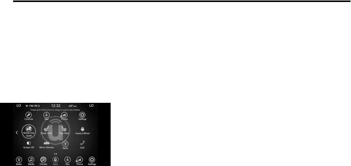
10
GETTING TO KNOW YOUR VEHICLE
VEHICLEUSERGUIDE—IFEQUIPPED
Access your Owner’s Information right through your Uconnect 4C or 4C NAV touchscreen system (if equipped).
To access the Vehicle User Guide on your Uconnect Touchscreen: Press the Uconnect Apps button.From there, pressthe Vehicle User Guide icon on your touchscreen. No Uconnect registration is required.
Uconnect 4C NAV With8.4–inch Display VehicleUser
Guide TouchscreenIcon
NOTE:
Vehicle User Guide features are not available while the vehicle is moving. If you try to access
while the vehicle is in motion, the system will display the message “Feature not available while the vehicle is in motion”.
Pre-Installed Features
Your User Guide — Updated in real-time
Touchscreen convenience
Maintenance schedules and information
Comprehensive icon and symbol glossary
Available when and where you need it
Customizable interface
Multilingual
Once you launch your Vehicle User Guide, you willbe abletoexplore your warrantyinformation and radio manual when and where you need them. Your Uconnect system displays the VehicleUser Guideonyourtouchscreenradioto assist in better understanding your vehicle. There’s no app to download, no phone to connectandno external device needed for playback. Plus, it’s updated throughout the year, in real-time, so it never goes out of date.
Features/Benefits
Pre-installed on your Uconnect touchscreen radio
Enhanced search and browsing capability
Robust NAV application (if equipped)
Add selected topics to a fast-access Favorites category
Icon and symbol glossary
Warranty information
Crucial driver information and assistance:
Operating Instructions
Warranty Information
Fluid Level Standards
Maintenance Schedules
Emergency Procedures
911 Contact and More
TIP:
When viewing a topic, tap the star icon to add it to your Favorites, for easy access in the future.
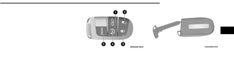
KEYS
Key Fob
The key fob allows you to lock or unlock the doors and trunk from distances up to approximately 66 ft (20 m). The key fob does not need to be pointed at the vehicle to activate the system.
NOTE:
SRT vehicles, equipped with the 6.2L Supercharged engine, come with three key fobs (two red and one black) that allow for different engine power levels.
KeyFob
1 — Trunk Open
2 — Unlock
3 — Lock
4 — Remote Start (If Equipped)
5 — PANIC Button
The key fob also contains an emergency key, which is stored in the rear of the key fob.
GETTING TO KNOW YOUR VEHICLE 11
11
2
EmergencyKey
The emergency key allows for entry into the vehicle should the battery in the vehicle or the key fob become depleted.Theemergencykey is also for locking/unlocking the glove compartment.Youcankeep theemergency key withyou when valet parking.
To remove the emergency key, slide the mechanical release button on the back of the key fob sideways with your thumb and then pull the key out with your other hand.
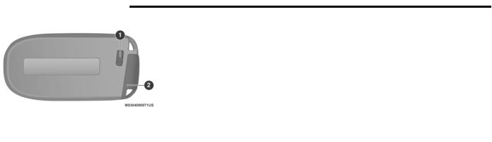
12 GETTING TO KNOW YOUR VEHICLE
EmergencyKey RemovalProcess
1 — Mechanical Release Button
2 — Emergency Key
NOTE:
In case theignitionswitchdoes notchange with thepushof abutton,thekeyfobmay havea low or fully depleted battery. A low key fob battery can be verified by referring to the instrument cluster, which will display directions to follow.
To Unlock The Doors
Push and release the unlock button on the key fob once to unlock the driver’s door or twice within five seconds to unlock all doors.
The turn signal lights will flash to acknowledge the unlock signal. The illuminated entry system will also be activated.
NOTE:
All door unlock settings can be programmed to your convenience through Uconnect Settings. Refer to “Uconnect Settings” in “Multimedia” for further information.
Unlock thedriver door on the first push of the key fob unlock button.
Unlock all doors on the first push of the key fob unlock button.
NOTE:
To unlock doors and trunk with passive entry, refer to “Keyless Enter-N-Go — Passive Entry” in “Doors” in this chapter for further information.
NOTE:
When you use the key fob to open any door, the courtesy lights, overhead lights, and approach lighting in the outside mirrors (if equipped) will turn on. Refer to “Interior Lights” in this chapter for further information.
1st Press Of Key Fob Unlocks
This feature lets you program the system to unlock either the driver’s door or all doors on the first push of the unlock button on the key fob.
To change the current setting, refer to “Uconnect Settings” in “Multimedia” for further information.
Flash Lights With Lock
This feature will cause the turn signal lights to flash when the doors are locked with the key fob. This feature can be turned on or turned off. To change the current setting, refer to “Uconnect Settings” in “Multimedia” for further information.
Headlight Illumination On Approach
This feature activates the headlights for up to 90 seconds when the doors are unlocked with the key fob. The time for this feature is programmable,onvehicles equipped,throughUconnect Settings. To change the current setting, refer to “Uconnect Settings” in “Multimedia” for further information.
To Unlatch The Trunk
Push the trunk button on the key fob two times within five seconds to unlatch the trunk.
If the vehicle is equipped with Passive Entry, refer to “Keyless Enter-N-Go — Passive Entry” in “Doors” in this chapter for further information.

To Lock The Doors And Trunk
Push andrelease the lock buttonon the key fob to lock all doors.
The turn signal lights will flash and the horn will chirp to acknowledge the signal if programmed. Refer to “Uconnect Settings” in “Multimedia” for further programmable information.
NOTE:
To lock the doors with passive entry, Refer to “KeylessEnter-N-Go—PassiveEntry”in“Doors” in this chapter for further information.
If one or more doors are open, or the trunk is open, the doors will lock. The doors will unlock automatically if the key fob is left inside the passenger compartment, otherwise the doors will stay locked.
Sound Horn With Lock
This feature will cause the horn to chirp when the doors are locked with the key fob. This feature can be turned on or turned off. To change the current setting, refer to “Uconnect Settings” in “Multimedia” for further information.
Using The Panic Alarm
To turn the Panic Alarm feature on or off, push the Panic buttononthe key fob.Whenthe Panic Alarmisactivated,theturnsignalswillflash,the horn will pulse on and off, and the interior lights will turn on.
The Panic Alarm will stay on for three minutes unless youturnitoffby either pushingthePanic button a second time or drive the vehicle at a speed of 15 mph (24 km/h) or greater.
NOTE:
The interior lights will turn off if you place the ignition in the ACC or ON/RUN position while the Panic Alarm is activated. However, the exterior lights and horn will remain on.
You may need to be less than 35 ft (11 m) from the vehicle when using the key fob to turn off the Panic Alarm due to the radio frequency noises emitted by the system.
GETTING TO KNOW YOUR VEHICLE 13
13
Key Fob Battery Replacement
The recommended replacement battery is one CR2032 battery.
NOTE:
Perchlorate Material — special handling may apply. See www.dtsc.ca.gov/hazardouswaste/perchlorate for further information.
2
Do not touch the battery terminals that are on the back housing or the printed circuit board.
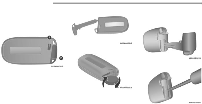
14 GETTING TO KNOW YOUR VEHICLE
1.Remove the emergency key by sliding the mechanical latch on the back of the key fobsidewayswithyour thumbandthenpull the emergency key out with your other hand.
EmergencyKeyRemoval
1 — Emergency Key Release Button
2 — Emergency Key
2.Separate the key fob halves using the tip of the emergency key, a #2 flat blade screwdriver, or a coin and gently pry the two halves of the key fob apart. Make sure not to damage the seal during removal.
NOTE:
Separating the case can also be done with the emergency key or a flat head screwdriver.
EmergencyKeyRemoval
Separating Case WithEmergencyKey
Separating Case With ACoin
Separating Case With AFlat BladeScrewdriver

KeyFob BatteryReplacement
3.Remove the battery by turning the back cover over (battery facing downward) and tapping it lightly on a solid surface such as a table or similar surface, and then replace the battery. When replacing the battery, match the (+) sign on the battery to the (+) signonthe insideof thebatteryclip,located on the back cover. Avoid touching the new battery with your fingers because skin oils may cause battery deterioration. If you touch a battery, clean it with rubbing alcohol.
4.To assemble the key fob case, snap the two halves together.
Programming Additional Key Fobs
Programming the key fob may be performed by an authorized dealer.
NOTE:
Once a key fob is programmed to a vehicle, it cannot be repurposed and reprogrammed to another vehicle.
Request For Additional Remote Controls
NOTE:
Only key fobs that are programmed to the vehicle electronics can be used to start and operate the vehicle. Once a key fob is programmed to a vehicle, it cannot be programmed to any other vehicle.
WARNING!
Always remove the key fobs from the vehicle and lock all doors when leaving the vehicle unattended.
For vehicles equipped with Keyless Enter-N-Go — Ignition, always remember to place the ignition in the OFF mode.
GETTING TO KNOW YOUR VEHICLE 15
15
|
Duplication of key fobs may be performed at an |
||
|
authorized dealer. This procedure consists of |
||
|
programming a blank key fob to the vehicle |
||
|
electronics. A blank key fob is one that has |
||
|
never been programmed. |
2 |
|
|
NOTE: |
||
|
WhenhavingtheSentryKeyImmobilizer system |
||
|
serviced, bring all vehicle keys with you to an |
||
|
authorized dealer. |
||
General Information |
||
|
Thefollowingregulatory statementappliesto all |
||
|
Radio Frequency (RF) devices equipped in this |
||
|
vehicle: |
||
|
This device complies with Part 15 of the FCC |
||
|
Rules and with Innovation, Science and |
||
|
EconomicDevelopmentCanadalicense-exempt |
||
|
RSS standard(s). Operation is subject to the |
||
|
following two conditions: |
1.This device maynot cause harmful interference, and
2.This device must accept any interference received, including interference that may cause undesired operation.

16 GETTING TO KNOW YOUR VEHICLE
Le présent appareil est conforme aux CNR d`Innovation, Science and Economic Development applicables aux appareils radio exempts de licence.L’exploitationestautoriséeauxdeux conditions suivantes:
1.l’appareil ne doit pas produire de brouillage, et
2.l’utilisateur de l’appareil doit accepter tout brouillage radioélectrique subi, même si le brouillage est susceptible d’en compromettre le fonctionnement.
La operación de este equipo está sujeta a las siguientes dos condiciones:
1.es posible que este equipo o dispositivo no cause interferencia perjudicial y
2.este equipo o dispositivo debe aceptar cualquier interferencia, incluyendo la que pueda causar su operación no deseada.
NOTE:
Changes or modifications not expressly approved by the party responsible for compliance could void the user’s authority to operate the equipment.
IGNITIONSWITCH
Keyless Push Button Ignition
This featureallows the driver to operate theignition withthe push of a button as long as the key fob is in the passenger compartment.
The Keyless Push Button Ignition has four operating positions, three of which are labeled and will illuminate when in position. The three positions are OFF, ACC, and ON/RUN. The fourth position is START. During START, RUN will illuminate.
NOTE:
If the ignition switch does not change with the push of a button, the key fob may have a low or depleted battery. In this situation, a back up method can be used to operate the ignition switch. Put the nose side (side opposite of the emergency key) of the key fob against the START/STOP ignition button and push to operate the ignition switch.
START/STOPIgnitionButton
1 — OFF
2 — ACC
3 — ON/RUN
The push button ignition can be placed in the following modes:
OFF
The engine is stopped.
Some electrical devices (e.g. central locking, alarm, etc.) are still available.
ACC
Engine is not started.
Some electrical devices are available.

ON/RUN
Driving position.
All the electrical devices are available.
START
The engine will start.
WARNING!
When exiting the vehicle, always remove the key fob from the vehicle and lock your vehicle.
Never leave children alone in a vehicle, or with access to an unlocked vehicle.
Allowing children to be in a vehicle unattended is dangerous for a number of reasons.Achildorotherscouldbeseriously or fatally injured. Children should be warned not to touch the parking brake, brake pedal or the gear selector.
Do not leave the key fob in or near the vehicle, or in a location accessible to children, and do not leave the ignition of a vehicle equipped with Keyless Enter-N-Go inthe ON/RUN mode.A child couldoperate power windows,other controls,ormove the vehicle.
WARNING! (Continued)
Do not leave children or animals inside parked vehicles in hot weather. Interior heat build-up may cause serious injury or death.
CAUTION!
An unlocked vehicle is an invitation for thieves. Always remove key fob from the vehicle and lock all doors when leaving the vehicle unattended.
NOTE:
Refer to «Starting The Engine» in «Starting And Operating» for further information.
Vehicle On Message
Whenopening thedriver’s door with the ignition in the ON/RUN position (engine not running), a chime will sound to remind you to place the ignition in the OFF position.
In addition to the chime, the Vehicle On message will display in the cluster (if equipped).
GETTING TO KNOW YOUR VEHICLE 17
17
NOTE:
The power window switches and power sunroof (if equipped) will remain active for three minutes after the ignition is placed in the OFF position. Opening either front door will cancel
this feature. The time for this feature is 2 programmable.
WARNING!
Before exiting a vehicle, always come to a complete stop, then shift the automatic transmission into PARK, apply the parking brake,place the engine intheOFFposition, remove the key fob from the vehicle and lock your vehicle. If equipped with Keyless Enter-N-Go, always make sure the keyless ignitionis in“OFF” position,remove the key fob from the vehicle and lock the vehicle.
Never leave children alone in a vehicle, or with access to an unlocked vehicle.
Allowing children to be in a vehicle unattended is dangerous for a number of reasons.Achildor otherscouldbeseriously or fatally injured. Children should be warned not to touch the parking brake, brake pedal or the gear selector.
(Continued)
(Continued)

18 GETTING TO KNOW YOUR VEHICLE
WARNING! (Continued)
Do not leave the key fob in or near the vehicle, or in a location accessible to children, and do not leave the ignition of a vehicle equipped with Keyless Enter-N-Go inthe ON/RUN mode.A child couldoperate power windows,other controls,ormove the vehicle.
Do not leave children or animals inside parked vehicles in hot weather. Interior heat build-up may cause serious injury or death.
CAUTION!
An unlocked vehicle is an invitation for thieves. Always remove key fob from the vehicle and lock all doors when leaving the vehicle unattended.
REMOTESTART—IFEQUIPPED
How To Use Remote Start — If Equipped
Push remote start button on the key fobtwicewithinfiveseconds.Pushing the remote start button a third time shuts the engine off.
To drive the vehicle, push the unlock button, and place the ignition in the ON/RUN position.
NOTE:
With remote start, the engine will only run for 15 minutes (timeout) unless the ignition is placed in the ON/RUN position.
Thevehiclemustbestartedwiththekey after two consecutive timeouts.
All of the following conditions must be met before the engine will remote start:
Gear selector in PARK
Doors closed
Hood closed
Trunk closed
Hazard switch off
Brake switch inactive (brake pedal not pushed)
Battery at an acceptable charge level
PANIC button not pushed
System not disabled from previous remote start event
Vehicle alarm system indicator flashing
Ignition in STOP/OFF position
Fuel level meets minimum requirement
Vehicle security alarm is not signaling an intrusion
Malfunction Indicator Light is not illuminated
WARNING!
Do not start or run an engine in a closed garage or confined area. Exhaust gas contains Carbon Monoxide (CO) which is odorlessandcolorless.CarbonMonoxideis poisonous and can cause serious injury or death when inhaled.
Keep key fobs away from children. Operation of the Remote Start System, windows, door locks or other controls could cause serious injury or death.
![]()
Remote Start Abort Message On The Instrument Cluster Display — If Equipped
The following messages will display in the instrument cluster display if the vehicle fails to remote start or exits remote start prematurely:
Remote Start Aborted — Door Open
Remote Start Aborted — Hood Open
Remote Start Aborted — Fuel Low
Remote Start Aborted — Trunk Open
Remote Start Disabled — Start Vehicle To Reset
The message will stay active until the ignition is placed in the ON/RUN position.
To Enter Remote Start Mode
Pushandreleasetheremotestartbuttononthe key fob twice within five seconds. The vehicle doors will lock, the parking lights will flash, and the horn will chirp twice (if programmed). Then, the engine will start,andthe vehicle will remain inthe Remote Start mode for a 15 minute cycle.
NOTE:
If an engine fault is present or fuel level is low, the vehicle will start and then shut down in 10 seconds.
The park lamps will turn on and remain on during Remote Start mode.
For security, power window and power sunroof operation (if equipped) are disabled when the vehicle is in the Remote Start mode.
The engine can be started two consecutive times with the key fob. However, the ignition must be cycled by pushing the START/STOP ignition button twice (or the ignition switch must be placed in the ON/RUN position) before you can repeat the start sequence for a third cycle.
To Exit Remote Start Mode Without Driving The Vehicle
Push and release the remote start button one time or allow the engine to run for the entire 15 minute cycle.
GETTING TO KNOW YOUR VEHICLE 19
19
NOTE:
To avoid unintentional shutdowns, the system will disable for two seconds after receiving a valid remote start request.
|
To Exit Remote Start Mode And Drive The |
2 |
Vehicle
Before the end of 15 minute cycle, push and release the unlock button on the key fob to unlock the doors and disarm the vehicle security alarm (if equipped). Then, prior to theend of the 15 minute cycle, push and release the START/STOP ignitionbutton.If the START/STOP ignition button is not present, insert the key fob into the ignition switch and place the switch in the ON/RUN position.
NOTE:
For vehicles not equipped with the Keyless Enter-N-Go — Passive Entry feature, the ignition switch must be in the ON/RUN position in order to drive the vehicle.
For vehicles not equipped with the Keyless Enter-N-Go — Passive Entry feature, the message “Remote Start Active — Insert Key

20 GETTING TO KNOW YOUR VEHICLE
and Turn To Run” will show in the instrument cluster display until you insert the key.
For vehicles equipped with the Keyless Enter-N-Go — Passive Entry feature, the message “Remote Start Active — Push Start Button” will show in the instrument cluster display until you push the START/STOP ignition button.
To Cancel Remote Start
Remote Starting will also cancel if any of the following occur:
The engine stalls or engine speed exceeds 2500 rpm.
Any engine warning lights come on.
Low Fuel Light turns on.
The hood is opened.
The hazard switch is pushed.
The gear selector is moved out of PARK.
The brake pedal is pushed.
Remote Start Comfort Systems — If Equipped
When remote start is activated, the heated steering wheel and driver heated seat features
will automatically turn on in cold weather. In warm weather, the driver vented seat feature willautomaticallyturn onwhentheremote start is activated. These features will stay onthrough the duration of remote start or until the ignition switch is placed in the ON/RUN position.
General Information
Thefollowingregulatory statementappliestoall Radio Frequency (RF) devices equipped in this vehicle:
This device complies with Part 15 of the FCC Rules and with Innovation, Science and EconomicDevelopmentCanadalicense-exempt RSS standard(s). Operation is subject to the following two conditions:
1.This device maynot cause harmful interference, and
2.This device must accept any interference received, including interference that may cause undesired operation.
Le présent appareil est conforme aux CNR d`Innovation, Science and Economic Development applicables aux appareils radio exempts de licence.L’exploitationestautoriséeauxdeux conditions suivantes:
1.l’appareil ne doit pas produire de brouillage, et
2.l’utilisateur de l’appareil doit accepter tout brouillage radioélectrique subi, même si le brouillage est susceptible d’en compromettre le fonctionnement.
La operación de este equipo está sujeta a las siguientes dos condiciones:
1.es posible que este equipo o dispositivo no cause interferencia perjudicial y
2.este equipo o dispositivo debe aceptar cualquier interferencia, incluyendo la que pueda causar su operación no deseada.
NOTE:
Changes or modifications not expressly approved by the party responsible for compliance could void the user’s authority to operate the equipment.
SENTRYKEY
The Sentry Key Immobilizer system prevents unauthorized vehicle operation by disabling the engine. The system does not need to be armed or activated. Operation is automatic,regardless of whether the vehicle is locked or unlocked.

The system uses a key fob, keyless push button ignition and a Radio Frequency (RF) receiver to prevent unauthorized vehicle operation. Therefore, only key fobs that are programmed to the vehicle can be used to start and operate the vehicle.The system cannotreprogram a key fob obtained from another vehicle.
After placing the ignition switch in the ON/RUN position,thevehiclesecuritylightwillturnonfor three seconds for a bulb check. If the light remains on after the bulb check, it indicates that there is a problem with the electronics. In addition, if the light begins to flash after the bulb check, it indicates that someone attemptedtostarttheenginewithaninvalidkey fob. In the event that a valid key fob is used to start the engine but there is an issue with the vehicle electronics, the engine will start and shut off after two seconds.
If the vehicle security light turns on during normal vehicle operation (vehicle running for longer than 10 seconds), it indicates that there is a fault in the electronics. Should this occur, havethevehicleservicedassoonaspossibleby an authorized dealer.
CAUTION!
The Sentry Key Immobilizer system is not compatible with some aftermarket remote starting systems. Use of these systems may result in vehicle starting problems and loss of security protection.
All of the key fobs provided with your new vehicle have been programmed to the vehicle electronics.
Key Programming
Programming key fobs may be performed at an authorized dealer.
Replacement Keys
NOTE:
Only key fobs that are programmed to the vehicle electronics can be used to start and operate the vehicle. Once a key fob is programmed to a vehicle, it cannot be programmed to any other vehicle.
GETTING TO KNOW YOUR VEHICLE 21
21
CAUTION!
Always remove the key fobs from the vehicle and lock all doors when leaving the
vehicle unattended.
2
For vehicles equipped with Keyless Enter-N-Go — Ignition, always remember to place the ignition in the OFF position.
NOTE:
Duplication of key fobs may be performed at an authorized dealer. This procedure consists of programming a blank key fob to the vehicle electronics. A blank key fob is one that has never been programmed.
WhenhavingtheSentryKeyImmobilizer system serviced, bring all vehicle keys with you to an authorized dealer.

22 GETTING TO KNOW YOUR VEHICLE
General Information
Thefollowing regulatory statementappliestoall Radio Frequency (RF) devices equipped in this vehicle:
This device complies with Part 15 of the FCC Rules and with Innovation, Science and EconomicDevelopmentCanadalicense-exempt RSS standard(s). Operation is subject to the following two conditions:
1.This device maynotcause harmful interference, and
2.This device must accept any interference received, including interference that may cause undesired operation.
Le présent appareil est conforme aux CNR d`Innovation, Science and Economic Development applicables aux appareils radio exempts de licence.L’exploitationestautoriséeauxdeux conditions suivantes:
1.l’appareil ne doit pas produire de brouillage, et
2.l’utilisateur de l’appareil doit accepter tout brouillage radioélectrique subi, même si le brouillage est susceptible d’en compromettre le fonctionnement.
La operación de este equipo está sujeta a las siguientes dos condiciones:
1.es posible que este equipo o dispositivo no cause interferencia perjudicial y
2.este equipo o dispositivo debe aceptar cualquier interferencia, incluyendo la que pueda causar su operación no deseada.
NOTE:
Changes or modifications not expressly approved by the party responsible for compliance could void the user’s authority to operate the equipment.
VEHICLESECURITYALARM—IFEQUIPPED
The vehicle security alarm monitors the vehicle doors for unauthorized entry and the keyless pushbuttonignitionforunauthorizedoperation. While the vehicle security alarm is armed, interior switches for door locks and trunk release are disabled. If something triggers the alarm, the vehicle security alarm will provide the following audible and visible signals: the horn will pulse, the park lamps and/or turn signals will flash, and the vehicle security light in the instrument cluster will flash.
To Arm The System
Follow these steps to arm the vehicle security alarm:
1.Make sure the vehicle’s ignition is placed in the OFF position. Refer to «Ignition Switch» in this chapter for further information.
2.Perform one of the following methods to lock the vehicle:
Push lock on the interior power door lock switch with the driver and/or passenger door open.
Push the lock button on the exterior Passive Entry Door Handle with a valid key fob available in the same exterior zone (refer to «Keyless Enter-N-Go — Passive Entry» in “Doors” in this chapter for further information).
Push the lock button on the key fob.
3.If any doors are open, close them.
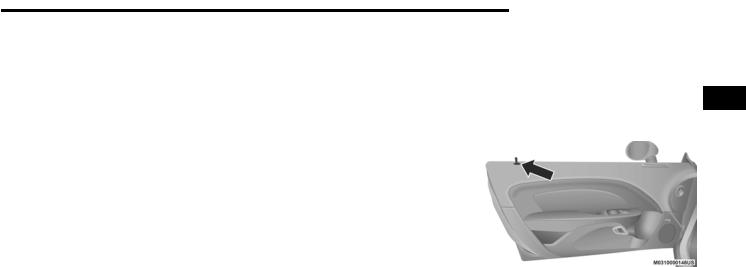
Security System Manual Override
The vehicle security alarm will not arm if you lock the doors using the manual door lock.
To Disarm The System
The vehicle security alarm can be disarmed using any of the following methods:
Push the unlock button on the key fob.
Grasp the Passive Entry Door Handle, if equipped. Refer to “Keyless Enter-N-Go — Passive Entry,” in “Doors” in this chapter for further information.
Push the Keyless Enter-N-Go ignition button (requires at least one valid key fob in the vehicle).
NOTE:
The driver’s door key cylinder and the trunk button on the key fob cannot arm or disarm the vehicle security alarm.
When the vehicle security alarm is armed, the interior power door lock switches will not unlock the doors.
Thevehiclesecurityalarmisdesignedtoprotect your vehicle. However, you can create conditions where the system will give you a false
alarm.If one of thepreviously describedarming sequences has occurred, the vehicle security alarm will arm regardless of whether you are in the vehicle or not. If you remain in the vehicle and open a door, the alarm will sound. If this occurs, disarm the vehicle security alarm.
If the vehicle security alarm is armed and the battery becomes disconnected, the vehicle security alarm will remain armed when the battery is reconnected; the exterior lights will flash, the horn will sound. If this occurs, disarm the vehicle security alarm.
Rearming Of The System
If something triggers the alarm, andno actionis takentodisarm it,thevehiclesecurity alarmwill turnthe horn off after 29 seconds,five seconds between cycles, up to eight cycles if the trigger remains active and the vehicle security alarm will rearm itself.
Tamper Alert
If something has triggered the vehicle security alarminyourabsence,thehornwillsoundthree times and the exterior lights will blink three times when you disarm the vehicle security alarm. Check the vehicle for tampering.
GETTING TO KNOW YOUR VEHICLE 23
23
DOORS
Manual Door Locks
To lock each door, push the door lock knob on eachdoor trimpaneldownward.Tounlockeach 2 door, pull the door lock knob on each door trim panel upward.
Door Lock Knob
If the door lock knob is down when you shut the door, the door will lock. Therefore, make sure the key fob is not inside the vehicle before closing the door.
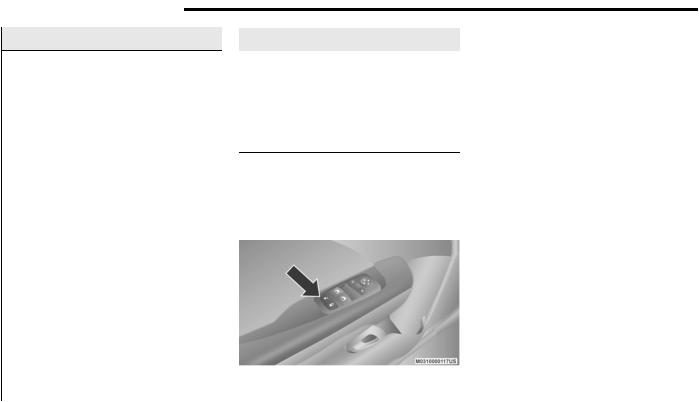
24 GETTING TO KNOW YOUR VEHICLE
WARNING!
For personal security and safety in the event of a collision, lock the vehicle doors before you drive as well as when you park and leave the vehicle.
Before exiting a vehicle, always shift the automatic transmission into PARK or the manual transmission into FIRST gear or REVERSE,apply the parking brake,turnthe vehicle OFF, remove the key fobs from the vehicle and lock all doors, and lock your vehicle.
When leaving the vehicle, always remove the key from the ignition and lock your vehicle. Unsupervised use of vehicle equipment may cause severe personal injuries and death.
Never leave children alone in a vehicle, or with access to an unlocked vehicle. Allowing children to be in a vehicle unattended is dangerous for a number of reasons.Achildorotherscouldbeseriously or fatally injured. Children should be warned not to touch the parking brake, brake pedal or gear selector.
(Continued)
WARNING! (Continued)
Do not leave the key fob in or near the vehicle, or in a location accessible to children, and do not leave the ignition of a vehicle equipped with Keyless Enter-N-Go in the ACC or ON/RUN mode. A child could operate power windows, other controls, or move the vehicle.
Power Door Locks
The power door lock switch is located on each doortrimpanel.Usethisswitchtolock orunlock the doors.
Power DoorLock Switch
The doorscanalsobelockedandunlockedwith the Keyless Enter-N-Go — Passive Entry system.
Referto“KeylessEnter-N-Go—PassiveEntry”in this section for further information.
If you push the power door lock switch while the ignitionis on,andeither door isopen,the power locks will not operate. This prevents you from accidentally locking the key fob in the vehicle. Turning off the ignition or closing the door will allow the locks to operate.If a door is open with the ignition either placedin the ACC or ON/RUN (engine not running) position, a chime will sound as a reminder.
Keyless Enter-N-Go — Passive Entry
The PassiveEntry system is anenhancementto the vehicle’s Remote Keyless Entry system and a feature of Keyless Enter-N-Go. This feature allows you to lock and unlock the vehicle’s door(s) without having to push the key fob lock or unlock buttons.
NOTE:
Passive Entry may be programmed on or off; refer to “Uconnect Settings” in “Multimedia” for further information.
If wearing gloves on your hands, or if it has been raining/snowing on the Passive Entry door handle, the unlock sensitivity can be affected, resulting in a slower response time.

If the vehicle is unlocked by Passive Entry andnodoor isopenedwithin60seconds,the vehicle will re-lock and if equipped will arm the security alarm.
Thekey fobmaynotbeable tobedetectedby the vehicle Passive Entry system if it is located next to a mobile phone, laptop or other electronic device; these devices may block the key fob’s wireless signal and prevent the Passive Entry handle from locking/unlocking the vehicle.
To Unlock From The Driver’s Side:
With a Passive Entry key fob within 5 ft (1.5 m) of the driver door handle, grab the front driver door handle to unlock thedriver’sdoor automatically. The interior door panel lock knob will raise when the door is unlocked.
Upon unlocking the door with Passive Entry,the turn signals will flashtwice, and the low beams, license plate lamp, and position lamps can be set to illuminate for 0, 30 (default), 60, or
90 seconds.
GrabThe DoorHandle To Unlock
NOTE:
If “Unlock All Doors 1st Press” is programmed, all doors will unlock when you grab hold of the front driver’s door handle. To select between “Unlock Driver Door 1st Press” and “Unlock All Doors 1st Press,” refer to “Uconnect Settings” in “Multimedia” for further information.
To Unlock From The Passenger Side:
With a Passive Entry key fob within 5 ft (1.5 m) of the passenger door handle, grab the front passenger door handle to unlock both doors automatically.The interior door panellock knob will raise when the door is unlocked.
GETTING TO KNOW YOUR VEHICLE 25
25
NOTE:
All doors will unlock when the front passenger door handle is grabbed regardless of the driver’sdoor unlockpreferencesetting(“Unlock Driver Door 1st Press” or “Unlock All Doors 1st
Press”). 2
PreventingInadvertentLockingOfPassiveEntry Key Fob In Vehicle (FOBIK-Safe)
To minimize the possibility of unintentionally locking a Passive Entry key fob inside your vehicle, the Passive Entry system is equipped with an automatic door unlock feature which will function if the ignition is in the OFF position.
FOBIK-Safe only executes in vehicles with Passive Entry. There are three situations that triggera FOBIK-SafesearchinanyPassive Entry vehicle.
1.A lock request is made by a valid Passive Entry key fob while a door is open.
2.A lock request is made by the Passive Entry door handle while a door is open.
3.A lock request is made by the door panel switch while the door is open.
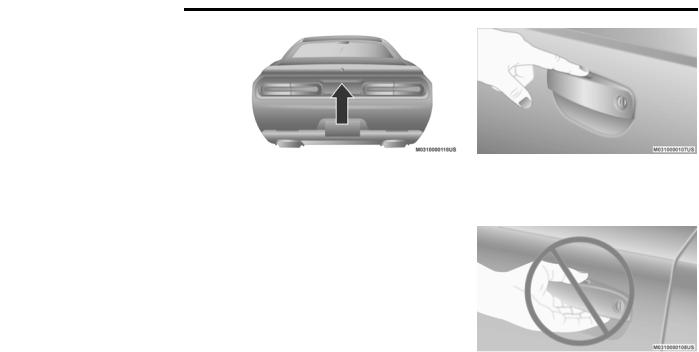
26 GETTING TO KNOW YOUR VEHICLE
When any of these situations occur, after all open doors areshut,the FOBIK-Safe searchwill be executed. If it finds a Passive Entry key fob inside the car, and it does not find any Passive Entry key fobs outside the car, the car will unlock and alert the customer.
NOTE:
The vehicle will only unlock the doors when a valid Passive Entry key fob is detected inside thevehicle,andnovalidPassive Entry keyfobis detected outside the vehicle. The vehicle will not unlock the doors when any of the following conditions are true:
Thedoorsaremanuallylockedusingthedoor lock knobs.
There is a valid Passive Entry key fob outside the vehicle and within 5 ft (1.5 m) of either Passive Entry door handle.
Three attempts are made to lock the doors using the door panel switch and then close the doors.
To Enter The Trunk:
With a Passive Entry key fob within 5 ft (1.5 m) of the deck lid, push the button located on the center of the light bar which is located on the deck lid above the license plate.
Trunk Passive EntryButton
NOTE:
If you inadvertently leave your vehicle’s Passive Entry key fob in the trunk and try to close the deck lid, the deck lid will automatically unlatch, unless another one of the vehicle’s Passive Entry key fobs is outside the vehicle and within 5 ft (1.5 m) of the deck lid.
To Lock The Vehicle’s Doors:
With one of the vehicle’s Passive Entry key fobs within 5 ft (1.5 m) of the driver or passenger front door handles, push the door handle lock button to lock both doors.
PushTheDoor Handle Button ToLock
Do NOTgrab thedoorhandle,whenpushingthe door handle button. This could unlock the door(s).
Do NOTGrabTheHandle When Locking

NOTE:
After pushing the door handle button, you mustwaittwoseconds beforeyoucanlock or unlock the doors, using either Passive Entry door handle. This is done to allow you to check if the vehicle is locked by pulling the door handle,withoutthevehiclereacting and unlocking.
The Passive Entry system will not operate if the key fob battery is depleted.
The vehicle doors can also be locked by using the key fob lock button or the lock button located on the vehicle’s interior door panel.
General Information
Thefollowing regulatory statementappliestoall Radio Frequency (RF) devices equipped in this vehicle:
This device complies with Part 15 of the FCC Rules and with Innovation, Science and EconomicDevelopmentCanadalicense-exempt RSS standard(s). Operation is subject to the following two conditions:
1.This device maynot cause harmful interference, and
2.This device must accept any interference received, including interference that may cause undesired operation.
Le présent appareil est conforme aux CNR d`Innovation, Science and Economic Development applicables aux appareils radio exempts de licence.L’exploitationestautoriséeauxdeux conditions suivantes:
1.l’appareil ne doit pas produire de brouillage, et
2.l’utilisateur de l’appareil doit accepter tout brouillage radioélectrique subi, même si le brouillage est susceptible d’en compromettre le fonctionnement.
La operación de este equipo está sujeta a las siguientes dos condiciones:
1.es posible que este equipo o dispositivo no cause interferencia perjudicial y
2.este equipo o dispositivo debe aceptar cualquier interferencia, incluyendo la que pueda causar su operación no deseada.
|
GETTING TO KNOW YOUR VEHICLE 27 |
|
|
NOTE: |
|
|
Changes or modifications not expressly |
|
|
approved by the party responsible for compli- |
|
|
ance could void the user’s authority to operate |
|
|
the equipment. |
2 |
Automatic Unlock Doors On Exit
The doors will unlock automatically on vehicles with power door locks if:
1.The Automatic Unlock Doors On Exit feature is enabled.
2.The vehicle was in motion, then speed returned to 0 mph (0 km/h) and the transmission is placed in PARK.
3.The driver door is opened.
4.The doors were not previously unlocked.
Automatic Unlock Doors On Exit Programming
To change the current setting, refer to “Uconnect Settings” in “Multimedia” for further information.
NOTE:
Use the Automatic Unlock DoorsOn Exitfeature in accordance with local laws.
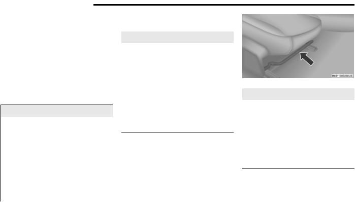
28 GETTING TO KNOW YOUR VEHICLE
Automatic Door Locks — If Equipped
The auto door lock feature default condition is enabled. When enabled, the door locks will lock automaticallywhenthevehicle’sspeedexceeds 15 mph (24 km/h). The auto door lock feature can be enabled or disabled by an authorized dealer per written request of the customer. Please see an authorized dealer for service.
SEATS
Seats are a part of the Occupant Restraint System of the vehicle.
WARNING!
It is dangerous to ride in a cargo area, inside or outside of a vehicle. In a collision, people riding in these areas are more likely to be seriously injured or killed.
Do not allow people to ride in any area of your vehicle that is notequipped withseats and seat belts. In a collision, people riding in these areas are more likely to be seriously injured or killed.
Besureeveryone in your vehicleis ina seat and using a seat belt properly.
Manual Adjustment (Front Seats) — If
Equipped
WARNING!
Adjusting a seat while the vehicle is moving isdangerous.Thesuddenmovementofthe seat could cause you to lose control. The seat belt might not be adjusted properly and you could be injured. Adjust the seat only while the vehicle is parked.
Do not ride with the seatback reclined so that the shoulder belt is no longer resting against your chest. In a collision you could slide under theseatbeltandbeseriously or even fatally injured. Use the recliner only when the vehicle is parked.
Manual Front Seats Forward/Rearward Adjustment
The adjusting bar is located at the front of the seat,nearthefloor.Pullthe bar upwardtomove the seat forward or rearward. Release the bar once the seat is in the desired position. Using body pressure, move forward and rearward on the seat to be sure that the seat adjusters have latched.
Adjusting BarLocation
WARNING!
Adjusting a seat while driving may be dangerous. Moving a seat while driving could result in loss of control which could cause a collision and serious injury or death.
Seats should be adjusted before fastening the seat belts and while the vehicle is parked. Serious injury or death could result from a poorly adjusted seat belt.
![]()
Manual Front Seat Recline
To adjust the seatback, lift the lever located on the outboard side of the seat, lean back to the desiredpositionandreleasethe lever.Toreturn the seatback, lift the lever, lean forward and release the lever.
Recline Lever
WARNING!
Do not ride with the seatback reclined so that the shoulder belt is no longer resting against your chest.In a collision you could slide under the seat belt, which could result in serious injury or death.
Manual Adjustment (Rear Seats)
Folding Rear Seat
The rear seatbacks can be folded forward to provide additional storage area. Pull on the loops located on the upper part of the rear seatback to fold down either or both seatbacks. These loops can be tucked away when not in use.
NOTE:
You may experience deformation in the seat cushion from the seat belt buckles if the seats are left folded for an extended period of time. This is normal and, by simply opening the seats to the open position,over time theseatcushion will return to its normal shape.
GETTING TO KNOW YOUR VEHICLE 29
29
2
Folded RearSeat
When the seatback is folded to the upright position, make sure it is latched by strongly pulling on the top of the seatback above the seat strap.
WARNING!
Be certain that the seatback is securely locked into position. If the seatback is not securely locked into position, the seat will not provide the proper stability for child seats and/or passengers. An improperly latched seat could cause serious injury.
(Continued)
Folding Rear Seatback Loop

30 GETTING TO KNOW YOUR VEHICLE
WARNING! (Continued)
The cargo area in the rear of the vehicle (withthe rear seatbacks in the locked-up or folded down position) should not be used as a play area by children when the vehicle isinmotion.They couldbeseriouslyinjured in a collision. Children should be seated and using the proper restraint system.
Power Seats — If Equipped
The power seat switches are located on the outboard side of the front seat cushions. The power seat switches are used to control the position of the seat.
Power Seat Switch
Adjusting The Seat Forward Or Rearward
The seatcanbe adjustedbothforwardand rearward.Pushthe seatswitchforwardor rearward. The seat willmove inthedirection of the switch. Release the switch when the desired position has been reached.
Adjusting The Seat Up Or Down
The height of the seats can be adjusted up or down. Pull upward or push downward on the seat switch; the seat will move in the direction of the switch. Release the switch when the desired position has been reached.
Tilting The Seat Up Or Down
The angle of the seat cushion can be adjusted up or down. Pull upward or push downward on the frontof the seatswitch.Thefrontoftheseat cushion will move in the direction of the switch. Release the switch when the desired position has been reached.
Power Lumbar — If Equipped
Vehicles equipped with power driver or passenger seats may also be equipped with power lumbar. The power lumbar switch is located on the outboard side of the power seat. Pushtheswitchforwardorrearward to increase or decrease the lumbar support. Push the
switchupwardordownwardtoraiseorlower the lumbar support.
PowerLumbar Switch
Heated Seats — If Equipped
On some models, the front seats may be equipped with heaters located in the seat cushions and seat backs.
WARNING!
Persons who are unable to feel pain to the skin because of advanced age, chronic illness,diabetes,spinalcord injury,medication, alcohol use, exhaustion or other physical condition must exercise care when using the seat heater. It may cause burns even at low temperatures, especially if used for long periods of time.
(Continued)

WARNING! (Continued)
Do not place anything on the seat or seatback that insulates against heat, such as a blanketorcushion.Thismaycausetheseat heatertooverheat.Sittinginaseatthathas been overheated could cause serious burns due to the increased surface temperature of the seat.
Front Heated Seats
The front heated seat control buttons are located within the climate or controls screen of the touchscreen.
You can choose from HI, LO, or OFF heat settings. The indicator arrows in touchscreen buttons indicate the level of heat in use. Two indicator arrows will illuminate for HI, and one for LO. Turning the heating elements off will return the user to the radio screen.
Press the heated seatbutton  once to turn the HI setting on.
Press the heated seat button  a second time to turn the LO setting on.
Press the heated seat button  a third time to turn the heating elements off.
If the HI-level setting is selected,the system will automatically switch to LO-level after approximately 60 minutes of continuous operation. At that time, the display will change from HI to LO, indicating the change. The LO-level setting will turn off automatically after approximately
45 minutes.
NOTE:
Once a heat setting is selected, heat will be felt within two to five minutes.
The engine must be running for the heated seats to operate.
Vehicles Equipped With Remote Start
On models thatare equipped with remote start, the heated seats can be programmed to come on during a remote start.
This feature can be programmed through the Uconnect system. Refer to “Uconnect Settings” in “Multimedia” for further information.
GETTING TO KNOW YOUR VEHICLE 31
31
WARNING!
|
Persons who are unable to feel pain to the |
|
|
skin because of advanced age, chronic |
|
|
illness,diabetes,spinalcord injury,medica- |
2 |
|
tion, alcohol use, exhaustion or other phys- |
ical condition must exercise care when using the seat heater. It may cause burns even at low temperatures, especially if used for long periods of time.
Do not place anything on the seat or seatback that insulates against heat, such as a blanketorcushion.Thismaycausetheseat heatertooverheat.Sittinginaseatthathas been overheated could cause serious burns due to the increased surface temperature of the seat.
Front Ventilated Seats — If Equipped
If your vehicleisequippedwith ventilatedseats, the seat cushion and seat back will have fans that draw the air from the passenger compartment and move air through fine perforations in the seat cover to help keep the driver and front passenger cooler in higher ambient temperatures. The fans operate at two speeds, HI and LO.

32 GETTING TO KNOW YOUR VEHICLE
The front ventilated seats control buttons are located within the Uconnect system. You can gain access to the control buttons through the climate screen or the controls screen.
Press the ventilated seat button  once to choose HI.
Press the ventilatedseatbutton  a second time to choose LO.
Press the ventilated seat button  a third time to turn the ventilated seat off.
NOTE:
The engine must be running for the ventilated seats to operate.
Vehicles Equipped With Remote Start
On models that are equipped with remote start, the ventilated seats can be programmed to come on during a remote start.
This feature can be programmed through the Uconnect system. Refer to “Uconnect Settings” in “Multimedia” for further information.
Vehicles Without Passenger Seating Installed
Allpassengeroccupantswithinthevehiclemust be in a seat equipped with a Seat Belt System and Head Restraint for the safety of the
passenger. If the passenger and/or rear seats have been removed, do not ride in those areas.
This vehicle has been designed to maximize total performance. In doing so, the deletion of passenger seats and/or rear seat may affect the NVH (Noise, Vibration, and Harshness) characteristics.Asa result,theinterior willbelouder overall.
WARNING!
If the passenger and/or rear seats have been removed, do not ride in those areas. In a collision, people riding in these areas are more likely to be seriously injured or killed.
If this vehiclewasnotfactoryequippedwith a passenger seat, NEVER attempt to install a passenger seat because the safety systems, including the air bags and seatbelt, may not properly protect you.
It is dangerous to ride in a cargo area, inside or outside of a vehicle. In a collision, people riding in this area are more likely to be seriously injured or killed.
(Continued)
WARNING! (Continued)
Only ride in available seating positions equipped with seat belt systems. Always properly wear your seat belt. Failure to do so could result in an increased risk of serious injury or death in the event of an accident.
Besure everyone inyour vehicleis in a seat and using a seat belt properly. Occupants, including the driver, should always wear their seat belts whether or not an air bag is also provided at their seating positions to minimize the risk of severe injury or death in the event of a crash.
All occupants, including the driver, should not operate a vehicle or sit in a vehicle’s seat if the head restraints are not in place of their proper positions in order to minimize the risk of neck injury in the event of a crash.
Head restraints should never be adjusted while the vehicle is in motion. Driving a vehicle with the head restraints improperly adjusted or removed could cause serious injury or death in the event of a collision.

Passenger Seat Easy Entry
Onthepassenger seat,pullforwardon thelever located on the side of the seatback in order to dump the seatback and slide the seat forward. You can also temporarily remove the seat belt from the guide loop on the seat and allow the seatbelttoretractoutof theway.Thisallowsfor easier access to the rear seat. To return the seat to a normal seating position, first return the seatback to its original recline location and then slide the entire seat back to the pre-set lock position.
EasyEntryLever
NOTE:
The front passenger seatneeds to slide back to a pre-set position for the fore-aft adjuster to be properly locked. For example, if the front passenger has the seat adjusted full rear and exits the vehicle to let a rear passenger enter usingtheeasy entry handle, the fore-aft adjuster needs to slide back about 2/3 of the way rearward to hit the lock position. If the adjuster is not returnedto this pre-set position, the seat will appear to be loose.
Also, if the front passenger uses the easy entry handle and then lifts up the recliner handle without moving the seat back to its original pre-set position, the recliner will not lock until it is moved to the full recline position.
HEADRESTRAINTS
Head restraints are designed to reduce the risk of injury by restricting head movement in the event of a rear impact. Head restraints should be adjusted sothatthetop of the headrestraint is located above the top of your ear.
GETTING TO KNOW YOUR VEHICLE 33
33
WARNING!
|
All occupants, including the driver, should |
|
|
not operate a vehicle or sit in a vehicle’s |
|
|
seat until the head restraints are placed in |
2 |
|
their proper positions in order to minimize |
the risk of neck injury in the event of a crash.
Head restraints should never be adjusted while the vehicle is in motion. Driving a vehicle with the head restraints improperly adjusted or removed could cause serious injury or death in the event of a collision.
NOTE:
Do not reverse the head restraints (making the rear of the head restraint face forward) in an attempttogainadditionalclearancetotheback of your head.
Reactive Head Restraints — Front Seats
The front driver and passenger seats are equipped with Reactive Head Restraints (RHR). In the event of a rear impact, the RHR will automatically extend forward minimizing the gap between the back of the occupants head and the RHR.

34 GETTING TO KNOW YOUR VEHICLE
The RHR will automatically return to their normal position following a rear impact. If the RHR do not return to their normal position, see an authorized dealer immediately.
Head Restraint
1 — Release Button
2 — Adjustment Button
3 — Seat Belt Loop
To raise the head restraint, pull upward on the head restraint. To lower the head restraint, pushtheadjustmentbuttonlocated atthebase oftheheadrestraintandpushdownwardonthe head restraint.
To remove the head restraint, remove the seat belt from the seat belt loop. Raise the head restraint as far as it can go. Then, push the adjustment button and the release button at
the base of each post while pulling the head restraint up. To reinstall the head restraint, put the head restraint posts into the holes while pushing the adjustment button and release button. Then, adjust it to the appropriate height.
NOTE:
It may be necessary to recline the front seat before removing the head restraint to provide enough clearance from the roof.
WARNING!
A loose head restraint thrown forward in a collision or hard stop could cause serious injury or death to occupants of the vehicle. Always securely stow removed head restraints in a location outside the occupant compartment.
ALL the head restraints MUST be reinstalledin the vehicle to properly protectthe occupants. Follow the re-installation instructions above prior to operating the vehicle or occupying a seat.
(Continued)
WARNING! (Continued)
Do not place items over the top of the Reactive Head Restraint, such as coats, seat covers or portable DVD players. These items may interfere with the operation of the Reactive Head Restraint in the event of a collision and could result in serious injury or death.
Rear Head Restraints
The rear outboard head restraints are non-adjustable and are designed to reduce the risk of injury by restricting head movement in the event of a rear impact.
Vehicles Without Passenger Seating Installed
Allpassengeroccupantswithinthevehiclemust be in a seat equipped with a Seat Belt System and Head Restraint for the safety of the passenger. If the passenger and/or rear seats have been removed, do not ride in those areas.
This vehicle has been designed to maximize total performance. In doing so, the deletion of passenger seats and/or rear seat may affect the NVH (Noise, Vibration, and Harshness) characteristics.As aresult,theinterior willbelouder overall.

WARNING!
If the passenger and/or rear seats have been removed, do not ride in those areas. In a collision, people riding in these areas are more likely to be seriously injured or killed.
If this vehiclewasnotfactoryequippedwith a passenger seat, NEVER attempt to install a passenger seat because the safety systems, including the air bags and seatbelt, may not properly protect you.
It is dangerous to ride in a cargo area, inside or outside of a vehicle. In a collision, people riding in this area are more likely to be seriously injured or killed.
Only ride in available seating positions equipped with seat belt systems. Always properly wear your seat belt. Failure to do so could result in an increased risk of serious injury or death in the event of an accident.
(Continued)
WARNING! (Continued)
Besureeveryone in your vehicleis ina seat and using a seat belt properly. Occupants, including the driver, should always wear their seat belts whether or not an air bag is also provided at their seating positions to minimize the risk of severe injury or death in the event of a crash.
All occupants, including the driver, should not operate a vehicle or sit in a vehicle’s seat if the head restraints are not in place of their proper positions in order to minimize the risk of neck injury in the eventof a crash.
Head restraints should never be adjusted while the vehicle is in motion. Driving a vehicle with the head restraints improperly adjusted or removed could cause serious injury or death in the event of a collision.
STEERINGWHEEL
Manual Tilt/Telescoping Steering Column —
If Equipped
GETTING TO KNOW YOUR VEHICLE 35
35
to lengthenor shortenthe steering column.The tilt/telescoping lever is located below the steering wheel at the end of the steering column.
2
ManualTilt/Telescoping ControlHandle
To unlock the steering column, pull the lever downward.Totiltthesteering column,movethe steeringwheel upwardor downwardas desired. Tolengthenor shortenthesteering column,pull the steering wheel outward or push it inward as desired.Tolock thesteering columnin position, push the lever upward until fully engaged.
This feature allows you to tilt the steering column upward or downward. It also allows you

36 GETTING TO KNOW YOUR VEHICLE
WARNING!
Do not adjust the steering column while driving. Adjusting the steering column while driving or driving with the steering column unlocked, could cause the driver to lose control of the vehicle. Failure to follow this warning may result in serious injury or death.
PowerTilt/TelescopingSteeringColumn—If Equipped
This feature allows you to tilt the steering column upward or downward. It also allows you to lengthenor shortenthe steering column.The power tilt/telescopingsteering columnswitchis located below the multifunction switch on the steering column.
Power Tilt/Telescoping Switch
To tilt the steering column, move the switch up or down as desired. To lengthen or shorten the steering column, pull the switch toward you or push the switch away from you as desired.
WARNING!
Do not adjust the steering column while driving. Adjusting the steering column while driving or driving with the steering column unlocked, could cause the driver to lose control of the vehicle. Failure to follow this warning may result in serious injury or death.
Heated Steering Wheel — If Equipped
The steering wheel contains a heating element that helps warm your hands in cold weather. The heated steering wheel has only one temperature setting. Once the heated steering wheel has been turned on, it will stay on for an average of 80 minutes before automatically shutting off. This time will vary based on environmental temperatures. The heated steering wheel can shut off early or may not turn on when the steering wheel is already warm.
The heated steering wheel control button is located within the Uconnect system. You can gain access to the control button through the climate screen or the controls screen.
Press the heated steering wheel button  once to turn the heating element on.
Press the heated steering wheel button  a second time to turn the heating element off.
NOTE:
The engine must be running for the heated steering wheel to operate.
Vehicles Equipped With Remote Start
On models thatare equipped with remote start, the heated steering wheel can be programmed to come on during a remote start through the Uconnect system. Refer to “Uconnect Settings” in “Multimedia” for further information.
WARNING!
Persons who are unable to feel pain to the skin because of advanced age, chronic illness,diabetes,spinalcord injury,medication, alcohol use, exhaustion, or other physical conditions must exercise care when using the steering wheel heater. It may cause burns even at low temperatures, especially if used for long periods.
(Continued)

WARNING! (Continued)
Donotplaceanythingonthesteeringwheel that insulates against heat, such as a blanketor steeringwheelcoversof anytype and material. This may cause the steering wheel heater to overheat.
MIRRORS
Automatic Dimming Mirror
The mirror head can be adjusted up, down, left, and right for various drivers. The mirror should be adjusted to center on the view through the rear window.
This mirror automatically adjusts for headlight glare from vehicles behind you.
NOTE:
The Automatic Dimming feature is disabled when the vehicle is in REVERSE to improve rear view viewing.
The Automatic Dimming feature can be turned on or off through the touchscreen.
Press the mirror dimmer button once to turn the feature on. The soft key button will illuminate when activated.
Press the mirror dimmer button a second time to turn the feature off, and the soft key button will no longer be illuminated.
Automatic DimmingMirror
CAUTION!
To avoid damage to the mirror during cleaning, never spray any cleaning solution directly onto the mirror. Apply the solution onto a clean cloth and wipe the mirror clean.
GETTING TO KNOW YOUR VEHICLE 37
37
Outside Mirrors
|
Toreceivemaximum benefit,adjust the outside |
|
|
mirror(s)tocenter ontheadjacentlaneoftraffic |
|
|
and a slight overlap of the view obtained from |
|
|
the inside mirror. |
2 |
NOTE:
The passenger side convex outside mirror will give a much wider view to the rear, and especially of the lane next to your vehicle.
WARNING!
Vehicles and other objects seen in an outside convex mirror will look smaller and farther away than they really are. Relying too much on side convex mirrors could cause you to collide with another vehicle or other object. Use your inside mirror when judging the size or distance of a vehicle seen in a side convex mirror.

38 GETTING TO KNOW YOUR VEHICLE
Power Mirrors
The power mirror controls are located on the driver’s door trim panel.
PowerMirrorControl
1 — Mirror Selection
2 — Mirror Adjustment
The power mirror controls consist of mirror select buttons and a four-way mirror control switch. To adjust a mirror, push either the L (left) or R (right) button to select the mirror that you want to adjust.
NOTE:
A light in the select button will illuminate indicating the mirror is activated and can be adjusted.
Using the mirror control switch, push on any of the four arrows for the direction that you want the mirror to move.
Heated Mirrors — If Equipped
Thesemirrors areheatedto meltfrost or ice. This feature will be activated whenever youturnontherearwindow
defroster (if equipped). Refer to “Climate Controls” in this chapter for further information.
Illuminated Vanity Mirrors
An illuminated vanity mirror is on the sun visor. To use the mirror, rotate the sun visor downward and swing the mirror cover upward. The light turns on automatically. Close the mirror cover to turn off the light.
“Slide-On-Rod” And Extender Features Of Sun Visor
To use the “Slide-On-Rod” feature of the sun visor, rotate the sun visor downward and swing the sun visor so itis parallel to the side window, pull the sun visor rearwards until it is in the desired position. To use the extender feature of thesunvisor,grabtheextenderwhichislocated at the rear of the visor and pull rearward.
Slide-On-RodExtender
Illuminated VanityMirror
![]()
EXTERIORLIGHTS
Headlight Switch
The headlight switch is located on the left side oftheinstrumentpanel.Thisswitchcontrolsthe operation of the headlights, parking lights, instrument panel lights, instrument panel light dimming, interior lights and fog lights (if equipped).
Headlight Switch
Rotate the headlight switch clockwise to the first detent for parking light and instrument panel light operation. Rotate the headlight switch to the second detent for headlight, parking light and instrument panel light operation. Push the switch to enable fog lights (if equipped).
Multifunction Lever
The multifunction lever controls the operation of the turn signals, headlight beam selection and passing lights. The multifunction lever is located on the left side of the steering column.
Multifunction Lever
Daytime Running Lights (DRLs) — If Equipped
The Daytime Running Lights will turn on when the engine is started and will remain on unless the headlamps are turned to the on position, the parking brake is applied, or the ignition is placed in the OFF position.
NOTE:
If allowed by law in the country in which the vehicle was purchased, the Daytime Running
GETTING TO KNOW YOUR VEHICLE 39
39
Lights can be turned on and off using the Uconnect System, refer to “Uconnect Settings” in “Multimedia” for further information.
High/Low Beam Switch
Push the multifunction lever away from you to 2 switch the headlights to high beam. Pull the multifunction lever toward you to switch the headlights back to low beam.
Automatic High Beam Headlamp Control — If Equipped
The Automatic High Beam Headlamp Control system provides increased forward lighting at night by automating high beam control through the use of a digital camera mounted on the windshield. This camera detects vehicle specific light and automatically switches from high beams to low beams until the approaching vehicle is out of view.
NOTE:
The Automatic High Beam Headlamp Control can be turned on or off using the Uconnect System. Refer to “Uconnect Settings” in “Multimedia” for further information.
Broken,muddy,or obstructedheadlightsand taillights of vehicles in the field of view will

40 GETTING TO KNOW YOUR VEHICLE
cause headlights to remain on longer (closer to the vehicle). Also, dirt, film, and other obstructions on the windshield or camera lens willcausethesystem tofunction improperly.
To opt out of the Advanced Auto High-Beam Sensitivity Control (default) and enter Reduced High-Beam Sensitivity Control (not recommended), toggle the high beam lever six full on/off cycles within 10 seconds of placing the ignition in the ON position. The system will return to the default setting upon placing the ignition in the OFF position.
If the windshield or Automatic High Beam Headlamp Control mirror is replaced,themirror must be re-aimedto ensure proper performance.See a local authorized dealer.
Flash-To-Pass
You can signal another vehicle with your headlights by lightly pulling the multifunction lever toward you. This will turn on the high beam headlights until the lever is released.
NOTE:
If the multifunction lever is held in the flash-to pass position for more than 20 seconds, the high beams will shut off.
Automatic Headlights
This system automatically turns the headlights on or off according to ambient light levels. To turn the system on, rotate the headlight switch counterclockwise to the AUTO position. When the system is on, the headlight time delay feature is also on. This means the headlights will stay on for up to 90 seconds after you place the ignition into the OFF position. The headlight time delay can be programmed 0/30/60/90 seconds.
Refer to “Uconnect Settings” in “Multimedia” for further information.
To turn the automatic system off, move the headlight switch out of the AUTO position.
NOTE:
The engine must be running before the headlights will come on in the automatic mode.
Parking Lights
Turn the headlight switch knob to the first detent to turn the parking lights on. This also turns on all instrument panel lighting.
Headlights On With Wipers
When this feature is active, the headlights will turn on after the wipers are turned on if the headlight switch is placed in the AUTO position
and the programmable feature is set to on. In addition, the headlights will turn off when the wipers are turned off if they were turned on by this feature.
NOTE:
The “HeadlightsOnWithWipers” featurecanbe turned on or off using the Uconnect System. Refer to “Uconnect Settings” in “Multimedia” for further information.
Headlight Time Delay
This feature provides the safety of headlight illumination for up to 90 seconds when leaving your vehicle in an unlit area with the headlight switch in the O (off) position.
To activate the delay feature, place the ignition in the OFF position while the headlights are still on. Then, turn off the headlights within 45 seconds. The delay interval begins when the headlight switch is turned off.
NOTE:
The lights mustbe turned off within 45 seconds of placing the ignition in the OFF position to activate this feature.
If you turn the headlights, park lights or ignition switch ON again, the system will cancel the delay.

If you turn the headlights off before the ignition, they will turn off in the normal manner.
NOTE:
The Headlight Time Delay is programmable using the Uconnect System, refer to “Uconnect Settings” in “Multimedia” for further information.
Lights-On Reminder
If the headlights or parking lights are on after the ignition is placed in the OFF position, a chime will sound to alert the driver when the driver’s door is opened.
Fog Lights — If Equipped
The front fog light switch is built into the headlight switch.
Fog Light Switch
To activate the front fog lights, turn on the parking lights or the low beam headlights and push the headlight switch. To turn off the front fog lights, either push the headlight switch a second time or turn off the headlight switch.
An indicator light in the instrument cluster display illuminates when the fog lights are turned on.
NOTE:
The fog lights will operate with the low beam headlights or parking lights on. However, selecting the high beam headlights will turn off the fog lights.
Turn Signals
Move the multifunction lever up or down and the arrows on each side of the instrument cluster display flashtoshowproper operationof the front and rear turn signal lights.
NOTE:
If either light remains on and does not flash, or there is a very fast flash rate, check for a defective outside light bulb. If an indicator fails to lightwhenthelever is moved,it would suggest that the indicator bulb is defective.
GETTING TO KNOW YOUR VEHICLE 41
41
A “TurnSignalOn”messagewillappearinthe instrument cluster display and a continuous chime will sound if the vehicle is driven more than 1 mile (1.6 km) with either turn signal
on.
2
Lane Change Assist — If Equipped
Tap the multifunction lever up or down once, without moving beyondthe detent,and the turn signal (right or left) will flash three times then automatically turn off.
INTERIORLIGHTS
The interior lights come on when a door is opened.
Toprotectthebattery,theinteriorlightswillturn offautomatically10 minutesaftertheignitionis placed in the OFF position. This will occur if the interior lights were switched on manually or are on because a door is open. The Battery Protection also includes the glove compartment light and the trunk light. To restore interior light operation after automatic battery protection is enabled (lights off), either place the ignition in the ON/RUN position or cycle the light switch.

42 GETTING TO KNOW YOUR VEHICLE
Map/Reading Lights
These lights are mounted between the sun visors on the overhead console. Each light is turned on by pushing the lens. Push the lens a second time to turn off the light. These lights also turn on when a door is opened, when the unlock button on the remote keyless entry key fob is pushed, or when the dimmer control is turned fully upward, past the second detent.
Map/Reading Lights
Ambient Light — If Equipped
The overhead console is equipped with an ambient light feature. This light casts illumination for improved visibility of the floor and center console area.
Rotate the right dimmer control upward or downward to increase or decrease the bright-
ness of the door handle lights, map pocket lights, and ambient light located in the overhead console.
Door Handle/AmbientLight Dimmer
Dimmer Controls
The dimmer control is part of the headlight switch and is located on the left side of the instrument panel.
DimmerControls
Withtheparkinglightsorheadlightson,rotating the left dimmer controlupward willincrease the brightness of the instrument panel lights and lighted cupholders (if equipped).
Instrument Panel Dimmer
Dome Light Position
Rotate the dimmer control completely upward to the second detent to turn on the interior lights.Theinteriorlightswillremainonwhenthe dimmer control is in this position.
Interior Light Defeat (Off)
Rotate the instrument panel dimmer control to the extreme bottom (O) off position.The interior lights will remain off when the doors are open.

Parade Mode (Daytime Brightness Feature)
Rotate the instrument panel dimmer control upward to the first detent. This feature brightens all text displays such as the odometer,instrumentcluster display,andradiowhen the parking lights or headlights are on.
WINDSHIELDWIPERSANDWASHERS
The multifunctionlever operates thewindshield wipers and washer when the ignition is placed in the ACC or ON/RUN position. The multifunction lever is located on the left side of the steering column.
WindshieldWiper/Washer Control
Wiper Operation
Rotate the end of the multifunction lever to the first detent, past the intermittent settings for low-speed wiper operation, or to the second detent past the intermittent settings for high-speed wiper operation.
CAUTION!
Turnthe windshieldwipers off whendriving through an automatic car wash. Damage to the windshield wipers may result if the wiper control is left in any position other than off.
In cold weather, always turn off the wiper switch and allow the wipers to return to the park position before turning off the engine. If the wiper switch is left on and the wipers freeze to the windshield, damage to the wiper motor may occur when the vehicle is restarted.
Always remove any buildup of snow that prevents the windshield wiper blades from returning to the off position. If the windshield wiper control is turned off and the blades cannot return to the off position, damage to the wiper motor may occur.
GETTING TO KNOW YOUR VEHICLE 43
43
Intermittent Wiper System
Use the intermittent wiper when weather conditions make a single wiping cycle with a variable pause between cycles desirable. Rotate the end of the multifunction lever to 2 the first detent position, and then turn the
end of the lever to select the desired delay interval. There are four delay settings, which allow you to regulate the wipe interval from a minimum of one cycle every second to a maximum of approximately 36 seconds between cycles. The delay intervals will double in duration when the vehicle speed is 10 mph (16 km/h) or less.
Windshield Washers
To use the washer,pushthe multifunction lever inward (toward the steering column) and hold it for as long as washer spray is desired.
If you activate the washer while the windshield wiper control is in the delay range, the wipers will operate for two wipe cycles after releasing the lever and then resume the intermittent interval previously selected.
If you activate the washer while the windshield wiper is turned off, the wipers will operate for three wipe cycles and then turn off.

44 GETTING TO KNOW YOUR VEHICLE
WARNING!
Sudden loss of visibility through the windshield couldleadtoa collision. You might not see other vehicles or other obstacles. To avoid sudden icing of the windshield during freezing weather, warm the windshield with the defroster before and during windshield washer use.
Mist Feature
Rotate the end of the lever downward to the MIST position to activate a single wipe cycle to clear off road mist or spray from a passing vehicle.Thewiperswillcontinuetooperateuntil you release the multifunction lever.
NOTE:
The mist feature does not activate the washer pump;therefore,nowasherfluidwillbesprayed on the windshield. The wash function must be used in order to spray the windshield with washer fluid.
Rain Sensing Wipers — If Equipped
This featuresenses rainor snowfallon the windshield and automatically activates the wipers for thedriver.Thefeatureisespeciallyusefulfor road splash or overspray from the windshield
washers of thevehicleahead.Rotatethe end of the multifunctionlever to one of four settings to activate this feature.
The sensitivity of the system can be adjusted with the multifunction lever. Wiper delay position 1 is the least sensitive, and wiper delay position 4 is the most sensitive. Setting 3 should be used for normal rain conditions. Settings 1 and 2 can be used if the driver desires less wiper sensitivity. Setting 4 can be usedif thedriver desires more sensitivity.Place the wiper switch in the off position when not using the system.
NOTE:
The Rain Sensing feature will not operate when the wiper switch is in the low or high-speed position.
The Rain Sensing feature may not function properly when ice, or dried salt water is present on the windshield.
Use of Rain-X or products containing wax or silicone may reduce Rain Sensing performance.
The Rain Sensing system has protection featuresfor the wiper blades and arms,and will not operate under the following conditions:
Low Ambient Temperature — When the ignitionisfirstplacedinthe ONposition,theRain Sensing system will not operate until the wiper switch is moved, vehicle speed is greater than 0 mph (0 km/h), or the outside temperature is greater than 32°F (0°C).
Transmission In NEUTRAL Position — When the ignition is ON, and the transmission is in the NEUTRAL position, the Rain Sensing system will not operate until the wiper switch is moved, vehicle speed is greater than
3 mph (5 km/h), or the gear selector is moved out of the NEUTRAL position.
NOTE:
RainSensingcan beturnedonandoffusingthe Uconnect System, refer to “Uconnect Settings” in “Multimedia” for further information.
CLIMATECONTROLS
The Climate Control system allows you to regulate the temperature, air flow, and direction of air circulating throughout the vehicle. The controls are located on the touchscreen (if equipped) and on the instrument panel below the radio.

GETTING TO KNOW YOUR VEHICLE 45
45
Automatic Climate Control Overview
2
Uconnect 4With 7–inch Display Automatic ClimateControls

46 GETTING TO KNOW YOUR VEHICLE
Uconnect 4C/4CNAV With 8.4–inch Display Automatic ClimateControls
NOTE:
Interior trims may vary. Depending on the engine equipped in the vehicle, there may be a “DRAG”, “Drive Mode”, or “SRT” button in place of a “Sport” button on the instrument panel.

GETTING TO KNOW YOUR VEHICLE 47
47
Automatic Climate Control Descriptions
Icon Description
|
MAX A/C Button |
||
|
Press and release the MAX A/C button on the touchscreen to change the current setting to the coldest output of air. The |
2 |
|
|
MAX A/C indicator illuminates when MAX A/C is on. Pressing and releasing the button again will cause the MAX A/C |
||
|
operation to exit. |
||
|
NOTE: |
||
|
The MAX A/C button is only available on the touchscreen. |
||
|
A/C Button |
||
|
Press and release this button on the touchscreen, or push the button on the faceplate to change the current setting. |
||
|
The A/C indicator illuminates when A/C is on. |
||
|
Recirculation Button |
||
|
Press and release this button on the touchscreen, or push the button on the faceplate, to change the system between |
||
|
recirculation mode and outside air mode. The Recirculation indicator illuminates when Recirculation is on. Recirculation |
||
|
can be used when outside conditions such as smoke, odors, dust, or high humidity are present. Recirculation can be used |
||
|
in all modes. Recirculation may be unavailable (button on the touchscreen greyed out) if conditions exist that could create |
||
|
fogging on the inside of the windshield. The A/C can be deselected manually without disturbing the mode control selection. |
||
|
Continuous use of the Recirculation mode may make the inside air stuffy and window fogging may occur. Extended use of |
||
|
this mode is not recommended. |

48 GETTING TO KNOW YOUR VEHICLE
|
Icon |
Description |
|
AUTO Button |
|
|
Set your desired temperature and press AUTO. AUTO will achieve and maintain your desired temperature by automatically |
|
|
adjusting the blower speed and air distribution. AUTO mode is highly recommended for efficiency. You can press and |
|
|
release this button on the touchscreen, or push the button on the faceplate, to turn AUTO on. The AUTO indicator |
|
|
illuminates when AUTO is on. Toggling this function will cause the system to switch between manual mode and automatic |
|
|
modes. |
|
|
Refer to “Automatic Operation” within this section for more information. |
|
|
Front Defrost Button |
|
|
Press and release the Front Defrost button on the touchscreen, or push and release the button on the faceplate, to change |
|
|
the current airflow setting to Defrost mode. The Front Defrost indicator illuminates when Front Defrost is on. Air comes from |
|
|
the windshield and side window demist outlets. When the defrost button is selected, the blower level may increase. Use |
|
|
Defrost mode with maximum temperature settings for best windshield and side window defrosting and defogging. When |
|
|
toggling the front defrost mode button, the climate system will return to the previous setting. |
|
|
Rear Defrost Button |
|
|
Press and release the Rear Defrost button on the touchscreen, or push and release the button on the faceplate, to turn on |
|
|
the rear window defroster and the heated outside mirrors (if equipped). The Rear Defrost indicator illuminates when the |
|
|
rear window defroster is on. The rear window defroster automatically turns off after 10 minutes. |
|
|
Driver And Passenger Temperature Up And Down Buttons |
|
|
Provides the driver and passenger with independent temperature control. Push the red button on the faceplate or |
|
|
touchscreen or press and slide the temperature bar towards the red arrow button on the touchscreen for warmer |
|
|
temperature settings.Push the blue button on the faceplate or touchscreen or press and slide the temperature bar towards |
|
|
the blue arrow on the touchscreen for cooler temperature settings. |
 Loading…