-
Contents
-
Table of Contents
-
Bookmarks
Quick Links
GE
Sensing
Druck TRX-II and TRX-II IS
Multi-function Calibrator
User manual — K319
[EN]
English
[FR]
French
[DE]
German
[IT]
Italian
[ES]
Spanish
[PT]
Portuguese
1 … 50
1 … 50
1 … 52
1 … 50
1 … 50
1 … 52
Related Manuals for GE Druck TRX-II
Summary of Contents for GE Druck TRX-II
-
Page 1
Sensing Druck TRX-II and TRX-II IS Multi-function Calibrator User manual — K319 [EN] English 1 … 50 [FR] French 1 … 50 [DE] German 1 … 52 [IT] Italian 1 … 50 [ES] Spanish 1 … 50 [PT] Portuguese 1 … 52… -
Page 3: Table Of Contents
Table of Contents INTRODUCTION …………….1 The TRX-II calibrator …………….1 Pressure Measurements and Calibrations……..1 Automatic Calibration…………….1 Standard Accessories……………1 Optional Accessories …………….1 FUNCTIONALITY…………….2 Parts Identification …………..2 Screens to work with …………3 Keys to work with …………….3 Functional Modes …………….4 Keystroking ………………5 POWER SOURCES ……………..6 SET-UP…………………8 Language Setting…………….8 Date and Time Settings …………..8…
-
Page 4
Menu Selections …………….23 Millivolts ………………24 Volts ………………..24 Milliamps/XMT …………….24 Ohms ………………… 25 Frequency ………………25 Counter ………………26 TO SIMULATE A THERMOCOUPLE ……….. 27 TO SIMULATE A RTD…………..27 SPECIAL SOURCE/SIMULATION FUNCTIONS……28 Step Mode………………28 Automatic Ramp Mode ………….. -
Page 5
IMPORTANT NOTE Unless otherwise indicated in the text, the operating instructions contained in this publication apply to both the TRXII Multi-Calibrator instruments and the TRXII IS Multi-Calibrator instruments. Only the intrinsically safe version of this Multi-Calibrator instrument (TRX II IS) may be used in hazardous areas and the following general warnings and conditions of use summarized below are applicable. -
Page 6
EN-iv K319 Issue 2… -
Page 7
K319 Issue 2 EN-v… -
Page 8
EN-vi K319 Issue 2… -
Page 9
K319 Issue 2 EN-vii… -
Page 10
Blank page EN-viii K319 Issue 2… -
Page 11: Introduction
INTRODUCTION The TRX-II Calibrator The Multi-Calibrator model TRX-II has been designed for testing and calibration of process instrumentation and portable test equipment. The unit provides data to comply with the ISO 9000 requirements for calibration. The TRX-II can be used to measure and source analogue and digital signals often used in an industrial environment.
-
Page 12: Functionality
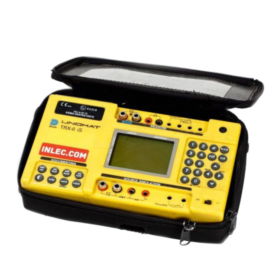
FUNCTIONALITY Parts Identification ( 1. POWER switch Switch the calibrator «ON» and «OFF». 2. EXT. POWER MEASURE Connector for external power source. Only suitable for optional line adaptor/charger #13603. 3.* Battery compartment cover Release screws to get access to batteries. 4.* Battery selector switch To select Alkaline or Rechargeable batteries.
-
Page 13: Screens To Work With
Screens to work with The TRX-II has four types of screen display to work with: • Menu Selection Screen ( Offers selection of choices. Move cursor with arrow keys to your choice. • Set-up Screen ( Move cursor with arrow keys to fill in the blanks. •…
-
Page 14: Functional Modes
# + EXE Opens set-up menu. Opens signal converter set-up screen. • The RCL key + Numerical key 1-9 Recalls stored key-pad operations (Keystroking). Press RCL first and hold, while pressing the next key. • The 0 key Changes the sign when display reads all zeros. •…
-
Page 15: Keystroking
Keystroking Keystroking is a solution to eliminate time consuming key-pad operations for frequently used functions. It can store 9 different sequences of key-pad operations. Recalling a sequence immediately returns to the function as stored. A sequence from any operational situation can be recalled. •…
-
Page 16: Power Sources
POWER SOURCES Power from internal batteries Internal power is obtained from 4x 1.5 V Alkaline batteries or four 1.2V, rechargeable batteries, Model R14, Baby or C size. Note: Not applicable for Model TRX-II IS. Installation of the batteries Switch the calibrator off before installing new batteries. Note: Not applicable for Model TRX-II IS.
-
Page 17
lowered. If the batteries do not reach their normal capacity after a 14 hour charging period, cycle complete discharging and charging at least twice. If the batteries remain weak they should be replaced. No particular brand of Ni-Cd is recommended although cells rated at 2.0 Ah have preference over the more generally available 1.8 Ah cells. -
Page 18: Set-Up
SET-UP Language Setting The TRX-II has multilingual software. The factory setting is ENGLISH. Setting the Language Leave the cursor at NONE at the measure and source menu and press # and EXE keys simultaneously to open the Set-up menu. Select LANGUAGE and press EXE. Select required language and press EXE.
-
Page 19: Pressure Units Setting
Changing the temperature scale Leave the cursor at NONE at the measure and source menu and press the # and EXE keys simultaneously to open the set-up menu. Select Temp. settings and press EXE. Select °C and press EXE to change from °C to °F or vice versa.
-
Page 20: Pressure Sensors
Changing the ACCESS CODE Leave the cursor at NONE at the measure and source menu and press # and EXE simultaneously to open the set-up menu. Select ACCESS CODE and press EXE. Type in the access code and press EXE to confirm. You are now in a mode where you can change the code.
-
Page 21: System Setting
System Setting Setting the backlight automatic mode Leave the cursor at NONE at the measure and source menu and press the # and EXE keys simultaneously to open the set-up menu. Select system and press EXE. Select BACKLIGHT and press EXE. Select required time or backlight timer MODE OFF and press EXE.
-
Page 22
Dec. Separate Leave the cursor at NONE at the measure and source menu and press the # and EXE keys simultaneously to open the set-up menu. Select DEC.SEPARATE and press EXE to change the settings from/ to, or vice versa. Press CE to leave the set-up menu. Key repeat Leave the cursor at NONE at the measure and source menu and press # and EXE keys simultaneously to open the set-up menu. -
Page 23: To Measure Electrical Signals
TO MEASURE ELECTRICAL SIGNALS Millivolts Select mV and DIRECT in the measure menu and press EXE to open the working screen. The upper window in the working screen indicates the measured millivolts reading. The range is 0-600 mV split into two (auto) ranges of 0 to 100 mV and 100 to 600 mV. Read the section “Scaled Readings”…
-
Page 24: Ohms
Ohms Select OHMS and DIRECT in the measure menu and press EXE to open the working screen. The upper window in the working screen indicates the measured ohms reading. The range is 0-2000 Ohms split into two (auto) ranges of 0 to 400 Ohms and 400 to 2000 Ohms. The excitation current is 0.9 mA.
-
Page 25: Counter
Pulse Counter Mode Two different pulse count modes are available: • Counts the pulses received in one minute. • Counts the pulses received in one hour. Select FREQ. in the measure menu and press EXE. Select P/MIN. of P/HOUR and press EXE. Enter a trigger level between 10 mV and 5.0 Volts and press EXE to open the working screen.
-
Page 26: Circuit Continuity Tester
Circuit Continuity Tester To check wiring continuity use the RTD measure terminals identified with Switch. If NONE has been selected in the source menu and SWITCH has been selected in the measure menu, press EXE to enter the continuity check mode. Closing the test loop will activate the built-in buzzer to prove that the wiring loop has a resistance of 2200 Ohms or less.
-
Page 27: Thermocouple Measurements
Remote temperature probe (not supplied by GE) With a Pt100 sensor you can measure cold junction temperatures from -200°C to 850°C (-328 … 1562 °F). Select EXTERNAL in the cold junction menu (CJ) and press EXE, to compensate the external cold junction microvolts automatically.
-
Page 28: To Measure A Rtd
Hand held thermometer (not supplied by GE) Read the thermometer while holding it close to the instrument terminals. Select MANUAL and open the screen to fill out the obtained reading. Press EXE to enter. Note that in this mode temperature changes at the instrument terminals can easily create calibration errors.
-
Page 29: To Measure Pressure
TO MEASURE PRESSURE The TRX-II Pressure Sensor Option The pressure sensor has been designed to calibrate pressure instruments in conjunction with the TRX-II multi- calibrator. The pressure sensor is powered from the TRX-II calibrator. It allows pressure instrument calibrations with ranges from: •-15 psi up to 10 000 psi •-1 bar up to 700 bar).
-
Page 30
Select the connected sensor from the available sensors with the key, and press EXE. Press CE to leave menu. The next menu gives you all the details of the selected sensor. This information should be checked with the sensor information on the connector. -
Page 31
Press # to unlock the switch reading. The switch reading will track the source reading again. Make sure that contacts are potential free. Calibration Hook-up for a Pressure Switch K319 Issue 2 EN-21… -
Page 32: Special Measurement Functions
SPECIAL MEASUREMENT FUNCTIONS Scaled Readings Except in temperature measure ranges all readings can be presented in a number of 5 digits and a sign. This number could represent an engineering unit like gallons/hour, revolutions/minute or any other relationship. This facility is available on both measurement and source functions.
-
Page 33: Sourcing Of Electrical Signals
SOURCING OF ELECTRICAL SIGNALS Menu Selections Select a source range and select DIRECT from the menu. It puts you right in the source mode. For other modes read section «Special Source Functions». The lower part of the screen shows the window for source functions.
-
Page 34: Millivolts
Millivolts Go to millivolts in the DIRECT mode to source any signal between — 10 mV and 100 mV. Adjustments are made with 1 microvolt resolution. If the adjusted source level can not be maintained the screen will prompt the warning CHECK LOOP. Note:‘Terminal to test lead’ junctions may create e.m.f.
-
Page 35: Ohms
Ohms Go through the OHM menu and select either the 0 to 400 or the 0 to 2000 Ohms range and enter the DIRECT mode. Resistance is simulated across the two terminals as shown. Connecting a third or fourth wire adapts the simulation to 3 or 4 wire input. Adjustment resolution is respectively 0.01 Ohms and 0.1 Ohms.
-
Page 36: Counter
as a voltage adjustable and regulated DC supply. Frequency source can take loads up to 32 mA at 24 Volts maximum. Frequency source range 0-100 Hz Go to frequency DIRECT mode to source any frequency signal between zero and 100 Hz. Adjustments are made with 0.01 Hz resolution.
-
Page 37: To Simulate A Thermocouple
TO SIMULATE A THERMOCOUPLE Work through the thermocouple menu and make the selections as required. Select the DIRECT mode to simulate any temperature within the range of the chosen thermocouple type. Adjustment resolution is 0.1 degree. For Cold Junction compensation considerations and different wiring methods read section «To simulate thermocouples»…
-
Page 38: Special Source/Simulation Functions
SPECIAL SOURCE/SIMULATION FUNCTIONS Step Mode In the step mode the TRX-II can generate preset source levels in four different ways; • Free programmable, Select PROGR Number of steps (2 to 10) and levels are free programmable. • 10% Divisions, Select 10% Free programmable span is automatically divided in 10 steps of 10% each.
-
Page 39: Automatic Ramp Mode
To source fixed steps manually Initially the TRX-II sources the preset value of step number 1 or 0%. Press the key to source the next step. Press the key to source the previous step. Press key to switch to the DIRECT mode to allow fine adjustments with the keys.
-
Page 40
Source in scaled readings Dial directly in scaled readings to SET a related source signal as set-up. Press EXE to actually source the signal. The functions are available for fine adjustment of the source. For details see the chapter “SPECIAL MEASUREMENT FUNCTIONS” section «Scaled Readings». -
Page 41: Transmitter Calibration
TRANSMITTER CALIBRATION In this function transmitter source and measure readings are both scaled in engineering units for quick comparison. Transmitter may be a linearized, non-linearized, 4-20 or 0-20 mA model for thermocouples or RTD. Setting-up a Calibration Leave the cursor at NONE in the measure menu and select the required source function.
-
Page 42: Pressure Transmitter Calibrations
Pressure Transmitter Calibrations 2-Wire transmitter; calibrator powered Make a calibration hook-up as indicated. Switch the TRX-II calibrator on to power the transmitter with 24 VDC. Select PRESSURE in the source menu and mA/XMT in the measure menu. Select the appropriate SENSOR in the source menu to read your calibration pressure.
-
Page 43: Transmitter Simulation
TRANSMITTER SIMULATION User can dial a temperature in degrees to source a 4-20 mA or 0-20 mA signal. This signal can be used to simulate transmitters at control system measure terminals. The simulated transmitter may be linearized or non-linearized. Function is available for all types of temperature sensors supplied as standard in the TRX-II.
-
Page 44: Programmable Signal Converter
PROGRAMMABLE SIGNAL CONVERTER With this unique feature any measure signal can be converted into any on the TRX-II available source signals with full galvanic isolation. Zero and span settings for both measure and source are fully programmable. Setting-up a signal converter Make all measure and source selections as you would do when you use measure and source functions separately in the DIRECT source mode.
-
Page 45: Ce Remarks
CE REMARKS The TRX-II prompts «ERROR» or «CHECK LOOP» whenever the functionality is influenced by electromagnetic disturbances. The results obtained during this state are unreliable. Error message The TRX-II is protected against failures by fast transient / burst. It restarts itself whenever this situation occurs and returns to the main screen.
-
Page 46: Supplement For Intrinsically Safe Calibrator Trx-Ii Is
SUPPLEMENT FOR INTRINSICALLY SAFE CALIBRATOR TRX-II iS Instructions for use Model TRX-II iS marked with label «Ex» has been built in accordance with European Norm II 2 (1) G EEx-ia IIC T5 and may be used in IEC defined zones 0,1 and 2. Special precautions for use in hazardous areas 1.
-
Page 47
Specifications For unit performances see TRX-II data sheet for the standard version. Deviations from the standard unit 0 … 21 mA Rmax. 600Ω Transmitter Supply: 12 VDC at the output terminals of the unit PCMCIA card: NOT supported, non removable COMPACTFLASH inside. Backlight: NOT supported. -
Page 48
Pressure sensor excitation output safety parameters: = 5.9 Volt Output safety parameters: = 8.0 mA max = 12.0 mW = 3.0 µF = 3.0 mH EN-38 K319 Issue 2… -
Page 49: Service, Repair And Parts
SERVICE, REPAIR AND PARTS Recalibration of the TRX-II Leave the cursor at NONE in the MEASURE and SOURCE menu and press the # and EXE keys simultaneously to open the set-up menu. Select CALIBRATION and press EXE. Fill out the access code and press EXE to open the calibration menu.
-
Page 50: Pressure Sensor
Pressure Sensor Installation of a new pressure sensor To add a new sensor specific data must be entered in the TRX-II memory. This is to correct the sensor linearity and hysteresis in the TRX-II calibrator. Each new sensor is delivered with the following data;…
-
Page 51: Fault Finding Procedures
range of the sensor. In general a dead weight tester is recommended. Calibration is performed at zero, 50% and full span only. Best straight line fit is established by the polynomial factors as entered during installation. Plug the sensor in the calibrator and switch the unit on. Wait 15 minutes to allow the unit to stabilize.
-
Page 52
2. When normally battery powered, check the contact springs for corrosion and spring tension. 3. Check total battery voltage with a voltmeter. Alkaline should read around 6 Volts and NiCd should read around 5 Volts when new or fully charged. 4. -
Page 53: Spare Parts List Trx-Ii
Spare Parts List TRX-II Part No. Power board Assy 201 Processor board Assy 200 Measure board Assy 202 Source board Assy 203 LCD display 22500/T Board spacers (3X) 25234 T/C terminal screws (4X) 25301 6x Test leads, 6x clips Assy 206 Operating Manual 25506 Line adaptor/charger 115 VAC…
-
Page 54: Specifications — Trx-Ii
EN-44 K319 Issue 2…
-
Page 55
K319 Issue 2 EN-45… -
Page 56
EN-46 K319 Issue 2… -
Page 57
Special functions Steps; 10 programmable, 10%, 20%, 25% div. step- ping by key or adj. timer Ramp; programmable travel time for up/down and dwell Scaling; in 5 digits and sign on all electrical ranges Temp. XMT cal.; both measure and source readings in temp. -
Page 58: Pressure Sensors (Optional)
Pressure Sensors (optional) Gauge: Part No: mbar #800 mbar #801 mbar #802 mbar #803 mbar #804 #805 #806 #807 #809 #810 #811 #813 #814 #815 #816 #817 1000 #818 1750 #819 2000 #820 2300 #821 3000 #822 5000 #823 6000 #824 7000 #825…
-
Page 59: Protocol For Rs232 System Integration
Pressure sensors Standard specification Reference Horizontal positioned sensor(s) 22 °C ±1°C(72 °F ±2°F), RH 45% ±15 (absolute sensors vertically positioned) Calibration Traceable to National Standards Temperature ±0.5% F.S. T.E.B. over 0-50 °C, typically 0.015% F.S./ °C effects Zero error Manual reset on TRX-II calibrator compensation Overpressure 2x pressure range up to 140 bar max.
-
Page 60: Return Goods Procedure
Returned Goods Procedure Should the unit become unserviceable and require repair it can be returned to the GE Druck Service Department. Please contact our Service Department, either by ‘phone or fax, to obtain a Returned Goods Authorization (RGA) number, providing the following information: •…
INTRODUCTION ……………………………………………………………………1
The TRX-II calibrator ………………………………………………………………1
Automatic Calibration………………………………………………………………1
Standard Accessories……………………………………………………………..1
Optional Accessories ………………………………………………………………1
FUNCTIONALITY…………………………………………………………………..2
…………………………………………………………….2
………………………………………………3
………………………………………………………………3
Functional Modes …………………………………………………………………..4
Keystroking ……………………………………………………………………………5
POWER SOURCES ……………………………………………………………….6
SET-UP…………………………………………………………………………………8
Language Setting……………………………………………………………………8
Date and Time Settings …………………………………………………………..8
Temperature Setting ……………………………………………………………….8
Pressure Units Setting …………………………………………………………….9
Access Code Settings……………………………………………………………..9
Pressure Sensors …………………………………………………………………10
Calibration……………………………………………………………………………10
System Setting……………………………………………………………………..11
Millivolts ………………………………………………………………………………13
Volts……………………………………………………………………………………13
Milliamps/XMT ……………………………………………………………………..13
Ohms ………………………………………………………………………………….14
Frequency……………………………………………………………………………14
Counter ……………………………………………………………………………….15
TO MEASURE A RTD…………………………………………………………..18
TO MEASURE PRESSURE …………………………………………………..19
Preparation ………………………………………………………………………….19
General ……………………………………………………………………………….19
Scaled Readings…………………………………………………………………..22
K319 Issue 2
EN-i
Note for Owners:
Guidesimo.com webproject is not a service center of GE trademark and does not carries out works for diagnosis and repair of faulty GE Druck TRX-II equipment. For quality services, please contact an official service center of GE company. On our website you can read and download documentation for your GE Druck TRX-II device for free and familiarize yourself with the technical specifications of device.
More Test Equipment Devices:
-
Aeroflex PSD60-1AF
OPERATION MANUAL PSD60-1AF FUEL QUANTITY SYSTEMS TEST SET MANUAL NUMBER:06-0605-0A (Hard Copy) E6-0605-0A (CD) REVISION:0 DATE:05/16/2007 WARNING: INFORMATION SUBJECT TO EXPORT CONTROL LAWS This manual may contain information subject to the International Traffic in Arms Regulation (ITAR) or the Export Administration Regulation (EAR) which may not be exported, released, or d …
PSD60-1AF Test Equipment, 16
-
Autel MaxiBAS BT609
i Trademarks Autel®, MaxiSys®, MaxiDAS®, MaxiScan®, MaxiCheck®, and MaxiRecorder® are trademarks of Autel Intelligent Technology Corp., Ltd., registered in China, the United States and other countries. All other marks are trademarks or registered trademarks of their respective holders. Copyright Information No part of this manual may be reproduced, stored in a retrieval system or tran …
MaxiBAS BT609 Test Equipment, 120
-
vinmetrica Dissolved Oxygen System
Dissolved Oxygen Manual 1 Version 1.7 Vinmetrica Dissolved Oxygen System User Manual The Vinmetrica Dissolved Oxygen system provides a simple, accurate and affordable way to determine oxygen concentrations in wine and other samples. Materials provided in the kit: 1. Electrolyte Solution (PN: SC-200- …
Dissolved Oxygen System Test Equipment, 7
-
Milwaukee MW10
SPECIFICATIONSRange 0.00 to 2.50 ppmResolution 0.01 ppmAccuracy±0.03 ppm ±3% of reading @ 25 °CTypical EMC Dev. ±0.01 ppmLight SourceLight Emitting Diode @525nmLight Detector Silicon PhotocellMethodAdaptation of USEPA method 330.5. The reaction between free chlorine and the DPD reagent causes a pink tint in the sample.Environment0 to 50°C (32 to 122 °F) max. 95% RH non-condensingBatter …
MW10 Measuring Instruments, 2
Recommended Documentation:
Table of Contents for GE Druck TRX-II:
-
K319 Issue 2 EN-vii English
-
EN-iv K319 Issue 2
-
EN-26 K319 Issue 2 as a voltage adjustable and regulated DC supply. Frequency source can take loads up to 32 mA at 24 Volts maximum. Frequency source range 0-100 Hz Go to frequency DIRECT mode to source any frequency signal between zero and 100 Hz. Adjustments are made with 0.01 Hz resolution. Frequency source range 0-20 kHz Go to frequency DIRECT mode to source any frequency signal between zero and 20.000 Hz. Adjustments are made with1 Hz resolution. Pulse source range 0-6000 P./Min. Sam
-
K319 Issue 2 EN-3 English Screens to work with The TRX-II has four types of screen display to work with: • Menu Selection Screen ( ) Offers selection of choices. Move cursor with arrow keys to your choice. • Set-up Screen ( ) Move cursor with arrow keys to fill in the blanks. • Working Screen ( ) Displays readings of measured and generated values. Source or simulated temperatures are set with the numerical key-pad or can be ramped up and down in different ways. •Help Screen Your
-
EN-30 K319 Issue 2 Source in scaled readings Dial directly in scaled readings to SET a related source signal as set-up. Press EXE to actually source the signal. The and key functions are available for fine adjustment of the source. For details see the chapter “SPECIAL MEASUREMENT FUNCTIONS” section «Scaled Readings». User Power Supplies Power supplies available for the user are designed to power transmitters, control and transducer Wheatstone br
-
K319 Issue 2 EN-49 English Pressure sensors Standard specification Specifications subject to change without notice. Protocol for RS232 System Integration Serial port settings Baud Rate: 9600 Parity: none Bits: 8 Stop: 1 Hardware handshake: none Reference Horizontal positioned sensor(s) 22 °C ±1°C(72 °F ±2°F), RH 45% ±15 (absolute sensors vertically positioned) Calibration Traceable to National Standards Temperature effects ±0.5% F.
-
K319 Issue 2 EN-17 English THERMOCOUPLE MEASUREMENTS Scroll through the thermocouple measure menu, making the required selections required. Press EXE to open the working screen; the measurement reading is shown in the upper window. Resolution is 0.1 degrees for most thermocouple types. Using compensation wires It is strongly recommended to use compensation wires for thermocouple simulations and measurements. Insert the compensation wire lead ends into the wire holes as indicated. Turn han
-
K319 Issue 2 EN-45 English Temperature Functions Range Resolution Accuracy Measure and Source RTD’s Pt50 (385) IEC 751 Pt100 (385) IEC 751 Pt200 (385) IEC 751 Pt500 (385) IEC 751 Pt1000 (385) IEC 751 D-100 (392) JIS 1604-1989 D-100 (392) JIS 1604-1981 Ni100 DIN 43760 Ni120 MINCO 7 — 120 Cu10 MINCO 16 — 9 (-200 … 850) °C (-328 … 1562) °F (-200 … 850) °C (-328 … 1562) °F (-200 … 850) °C (-328 … 1562)
-
EN-48 K319 Issue 2 Pressure Sensors (optional) Gauge: Part No: 0 — 1 psi / 70 mbar #800 0 — 2.5 psi / 175 mbar #801 0 — 3 psi / 200 mbar #802 0 — 5 psi / 350 mbar #803 0 — 10 psi / 700 mbar #804 0 — 15 psi / 1 bar #805 0 — 20 psi / 1.4 bar #806 0 — 30 psi / 2 bar #807 0 — 50 psi / 3.5 bar #809 0 — 75 psi / 5 bar #810 0 — 100 psi / 7 bar #811 0 — 150 psi / 10 bar #813 0 — 300 psi / 20 bar #814 0 — 450 psi / 30 bar #815 0 — 500 psi / 35 bar #816
-
GE Sensing Druck TRX-II and TRX-II IS Multi-function Calibrator User manual — K319 [EN] English 1 … 50 [FR] French 1 … 50 [DE] German 1 … 52 [IT] Italian 1 … 50 [ES] Spanish 1 … 50 [PT] Portuguese 1 … 52
-
K319 Issue 2 EN-25 English Ohms Go through the OHM menu and select either the 0 to 400 or the 0 to 2000 Ohms range and enter the DIRECT mode. Resistance is simulated across the two terminals as shown. Connecting a third or fourth wire adapts the simulation to 3 or 4 wire input. Adjustment resolution is respectively 0.01 Ohms and 0.1 Ohms. Frequency Frequencies are symmetrical square waves and -70 mV zero based. Frequency is set by the an
-
EN-8 K319 Issue 2 SET-UP Language Setting The TRX-II has multilingual software. The factory setting is ENGLISH. Setting the Language Leave the cursor at NONE at the measure and source menu and press # and EXE keys simultaneously to open the Set-up menu. Select LANGUAGE and press EXE. Select required language and press EXE. Press CE to leave the set-up menu. Date and Time Settings The TRX-II is equipped with a real time clock. At calibration, the c
-
EN-32 K319 Issue 2 Pressure Transmitter Calibrations 2-Wire transmitter; calibrator powered Make a calibration hook-up as indicated. Switch the TRX-II calibrator on to power the transmitter with 24 VDC. Select PRESSURE in the source menu and mA/XMT in the measure menu. Select the appropriate SENSOR in the source menu to read your calibration pressure.
Questions, Opinions and Exploitation Impressions:
You can ask a question, express your opinion or share our experience of GE Druck TRX-II device using right now.
Download or browse on-line these Operation & User’s Manual for GE Druck TRX-II Test Equipment.
Summary of Contents:
 |
[Page 1] GE Druck TRX-II GE Sensing Druck TRX-II and TRX-II IS Multi-function Calibrator User manual — K319 [EN] English 1 … 50 [FR] French 1 … 50 [DE] German 1 … 52 [IT] Italian 1 … 50 [ES] Spanish 1 … 50 [PT] Portuguese 1 … 52 |
 |
[Page 2] GE Druck TRX-II … |
 |
[Page 3] GE Druck TRX-II K319 Issue 2 EN-i English Table of Contents INTRODUCTION ……………………………………………………………………1 The TRX-II calibrator ………………………………………………………………1 Pressure Measurem… |
 |
[Page 4] GE Druck TRX-II EN-ii K319 Issue 2 Menu Selections …………………………………………………………………. 23 Millivolts …………………………………………………………………………….. 24 Volts ………………………. |
 |
[Page 5] GE Druck TRX-II K319 Issue 2 EN-iii English IMPORTANT NOTE Unless otherwise indicated in the text, the operating instructions contained in this publication apply to both the TRXII Multi-Calibrator instruments and the TRXII IS Multi-Calibrator instruments. Only the… |
 |
[Page 6] GE Druck TRX-II EN-iv K319 Issue 2 |
 |
[Page 7] GE Druck TRX-II K319 Issue 2 EN-v English |
 |
[Page 8] GE Druck TRX-II EN-vi K319 Issue 2 |
 |
[Page 9] GE Druck TRX-II K319 Issue 2 EN-vii English |
 |
[Page 10] GE Druck TRX-II EN-viii K319 Issue 2 Blank page |
 |
[Page 11] GE Druck TRX-II K319 Issue 2 EN-1 English INTRODUCTION The TRX-II Calibrator The Multi-Calibrator model TRX-II has been designed for testing and calibration of process instrumentation and portable test equipment. The unit provides data to comply with the ISO 9000 … |
 |
[Page 12] GE Druck TRX-II EN-2 K319 Issue 2 FUNCTIONALITY Parts Identification ( ) 1. POWER switch Switch the calibrator «ON» and «OFF». 2. EXT. POWER MEASURE Connector for external power source. Only suitable for optional line adaptor/charger #13603. 3.* … |
 |
[Page 13] GE Druck TRX-II K319 Issue 2 EN-3 English Screens to work with The TRX-II has four types of screen display to work with: • Menu Selection Screen ( ) Offers selection of choices. Move cursor with arrow keys to your choice. • Set-up Screen ( ) Move cursor with ar… |
 |
[Page 14] GE Druck TRX-II EN-4 K319 Issue 2 # + EXE Opens set-up menu. Opens signal converter set-up screen. • The RCL key + Numerical key 1-9 Recalls stored key-pad operations (Keystroking). Press RCL first and hold, while pressing the next key. • The 0 key Changes the… |
 |
[Page 15] GE Druck TRX-II K319 Issue 2 EN-5 English Keystroking Keystroking is a solution to eliminate time consuming key-pad operations for frequently used functions. It can store 9 different sequences of key-pad operations. Recalling a sequence immediately returns to t… |
 |
[Page 16] GE Druck TRX-II EN-6 K319 Issue 2 POWER SOURCES Power from internal batteries Internal power is obtained from 4x 1.5 V Alkaline batteries or four 1.2V, rechargeable batteries, Model R14, Baby or C size. Note: Not applicable for Model TRX-II IS. Installation of the … |
 |
[Page 17] GE Druck TRX-II K319 Issue 2 EN-7 English lowered. If the batteries do not reach their normal capacity after a 14 hour charging period, cycle complete discharging and charging at least twice. If the batteries remain weak they should be replaced. No particular … |
 |
[Page 18] GE Druck TRX-II EN-8 K319 Issue 2 SET-UP Language Setting The TRX-II has multilingual software. The factory setting is ENGLISH. Setting the Language Leave the cursor at NONE at the measure and source menu and press # and EXE keys simultaneously to open the Set-up… |
 |
[Page 19] GE Druck TRX-II K319 Issue 2 EN-9 English Changing the temperature scale Leave the cursor at NONE at the measure and source menu and press the # and EXE keys simultaneously to open the set-up menu. Select Temp. settings and press EXE. Select °C and press EXE to … |
 |
[Page 20] GE Druck TRX-II EN-10 K319 Issue 2 Changing the ACCESS CODE Leave the cursor at NONE at the measure and source menu and press # and EXE simultaneously to open the set-up menu. Select ACCESS CODE and press EXE. Type in the access code and press EXE to confirm. Yo… |
 |
[Page 21] GE Druck TRX-II K319 Issue 2 EN-11 English System Setting Setting the backlight automatic mode Leave the cursor at NONE at the measure and source menu and press the # and EXE keys simultaneously to open the set-up menu. Select system and press EXE. Select BACKLIG… |
 |
[Page 22] GE Druck TRX-II EN-12 K319 Issue 2 Dec. Separate Leave the cursor at NONE at the measure and source menu and press the # and EXE keys simultaneously to open the set-up menu. Select DEC.SEPARATE and press EXE to change the settings from/ to, or vice versa. Press CE… |
 |
[Page 23] GE Druck TRX-II K319 Issue 2 EN-13 English TO MEASURE ELECTRICAL SIGNALS Millivolts Select mV and DIRECT in the measure menu and press EXE to open the working screen. The upper window in the working screen indicates the measured millivolts reading. The range is … |
 |
[Page 24] GE Druck TRX-II EN-14 K319 Issue 2 Ohms Select OHMS and DIRECT in the measure menu and press EXE to open the working screen. The upper window in the working screen indicates the measured ohms reading. The range is 0-2000 Ohms split into two (auto) ranges of 0 t… |
 |
[Page 25] GE Druck TRX-II K319 Issue 2 EN-15 English Pulse Counter Mode Two different pulse count modes are available: • Counts the pulses received in one minute. • Counts the pulses received in one hour. Select FREQ. in the measure menu and press EXE. Select P/MIN. of … |
 |
[Page 26] GE Druck TRX-II EN-16 K319 Issue 2 Circuit Continuity Tester To check wiring continuity use the RTD measure terminals identified with Switch. If NONE has been selected in the source menu and SWITCH has been selected in the measure menu, press EXE to enter the co… |
 |
[Page 27] GE Druck TRX-II K319 Issue 2 EN-17 English THERMOCOUPLE MEASUREMENTS Scroll through the thermocouple measure menu, making the required selections required. Press EXE to open the working screen; the measurement reading is shown in the upper window. Resolution is … |
 |
[Page 28] GE Druck TRX-II EN-18 K319 Issue 2 Hand held thermometer (not supplied by GE) Read the thermometer while holding it close to the instrument terminals. Select MANUAL and open the screen to fill out the obtained reading. Press EXE to enter. Note that in this mode… |
 |
[Page 29] GE Druck TRX-II K319 Issue 2 EN-19 English TO MEASURE PRESSURE The TRX-II Pressure Sensor Option The pressure sensor has been designed to calibrate pressure instruments in conjunction with the TRX-II multi- calibrator. The pressure sensor is powered from the TRX… |
 |
[Page 30] GE Druck TRX-II EN-20 K319 Issue 2 Select the connected sensor from the available sensors with the and key, and press EXE. Press CE to leave menu. The next menu gives you all the details of the selected sensor. This information should be checked with the sen… |
 |
[Page 31] GE Druck TRX-II K319 Issue 2 EN-21 English Press # to unlock the switch reading. The switch reading will track the source reading again. Make sure that contacts are potential free. Calibration Hook-up for a Pressure Switch |
 |
[Page 32] GE Druck TRX-II EN-22 K319 Issue 2 SPECIAL MEASUREMENT FUNCTIONS Scaled Readings Except in temperature measure ranges all readings can be presented in a number of 5 digits and a sign. This number could represent an engineering unit like gallons/hour, revolutions/… |
 |
[Page 33] GE Druck TRX-II K319 Issue 2 EN-23 English SOURCING OF ELECTRICAL SIGNALS Menu Selections Select a source range and select DIRECT from the menu. It puts you right in the source mode. For other modes read section «Special Source Functions». The lower p… |
 |
[Page 34] GE Druck TRX-II EN-24 K319 Issue 2 Millivolts Go to millivolts in the DIRECT mode to source any signal between — 10 mV and 100 mV. Adjustments are made with 1 microvolt resolution. If the adjusted source level can not be maintained the screen will prompt the war… |
 |
[Page 35] GE Druck TRX-II K319 Issue 2 EN-25 English Ohms Go through the OHM menu and select either the 0 to 400 or the 0 to 2000 Ohms range and enter the DIRECT mode. Resistance is simulated across the two terminals as shown. Connecting a third or fourth wire adapts t… |
 |
[Page 36] GE Druck TRX-II EN-26 K319 Issue 2 as a voltage adjustable and regulated DC supply. Frequency source can take loads up to 32 mA at 24 Volts maximum. Frequency source range 0-100 Hz Go to frequency DIRECT mode to source any frequency signal between zero and 100 H… |
 |
[Page 37] GE Druck TRX-II K319 Issue 2 EN-27 English TO SIMULATE A THERMOCOUPLE Work through the thermocouple menu and make the selections as required. Select the DIRECT mode to simulate any temperature within the range of the chosen thermocouple type. Adjustment reso… |
 |
[Page 38] GE Druck TRX-II EN-28 K319 Issue 2 SPECIAL SOURCE/SIMULATION FUNCTIONS Step Mode In the step mode the TRX-II can generate preset source levels in four different ways; • Free programmable, Select PROGR Number of steps (2 to 10) and levels are free programmable. �… |
 |
[Page 39] GE Druck TRX-II K319 Issue 2 EN-29 English To source fixed steps manually Initially the TRX-II sources the preset value of step number 1 or 0%. Press the key to source the next step. Press the key to source the previous step. Press key to switch to the DIR… |
 |
[Page 40] GE Druck TRX-II EN-30 K319 Issue 2 Source in scaled readings Dial directly in scaled readings to SET a related source signal as set-up. Press EXE to actually source the signal. The and key functions are available for fine adjustment of the source. For detai… |
 |
[Page 41] GE Druck TRX-II K319 Issue 2 EN-31 English TRANSMITTER CALIBRATION In this function transmitter source and measure readings are both scaled in engineering units for quick comparison. Transmitter may be a linearized, non-linearized, 4-20 or 0-20 mA model for ther… |
 |
[Page 42] GE Druck TRX-II EN-32 K319 Issue 2 Pressure Transmitter Calibrations 2-Wire transmitter; calibrator powered Make a calibration hook-up as indicated. Switch the TRX-II calibrator on to power the transmitter with 24 VDC. Select PRESSURE in the source menu and mA/X… |
 |
[Page 43] GE Druck TRX-II K319 Issue 2 EN-33 English TRANSMITTER SIMULATION User can dial a temperature in degrees to source a 4-20 mA or 0-20 mA signal. This signal can be used to simulate transmitters at control system measure terminals. The simulated transmitter may be … |
 |
[Page 44] GE Druck TRX-II EN-34 K319 Issue 2 PROGRAMMABLE SIGNAL CONVERTER With this unique feature any measure signal can be converted into any on the TRX-II available source signals with full galvanic isolation. Zero and span settings for both measure and source are fully… |
 |
[Page 45] GE Druck TRX-II K319 Issue 2 EN-35 English CE REMARKS The TRX-II prompts «ERROR» or «CHECK LOOP» whenever the functionality is influenced by electromagnetic disturbances. The results obtained during this state are unreliable. Error message The… |
 |
[Page 46] GE Druck TRX-II EN-36 K319 Issue 2 SUPPLEMENT FOR INTRINSICALLY SAFE CALIBRATOR TRX-II iS Instructions for use Model TRX-II iS marked with label «Ex» has been built in accordance with European Norm II 2 (1) G EEx-ia IIC T5 and may be used in IEC defined… |
 |
[Page 47] GE Druck TRX-II K319 Issue 2 EN-37 English Specifications For unit performances see TRX-II data sheet for the standard version. Deviations from the standard unit 0 … 21 mA Rmax. 600Ω Transmitter Supply: 12 VDC at the output terminals of the unit PCMCIA card: NO… |
 |
[Page 48] GE Druck TRX-II EN-38 K319 Issue 2 Pressure sensor excitation output safety parameters: U o = 5.9 Volt Output safety parameters: I o = 8.0 mA max P o = 12.0 mW C o =3.0 µF L o =3.0 mH |
 |
[Page 49] GE Druck TRX-II K319 Issue 2 EN-39 English SERVICE, REPAIR AND PARTS Recalibration of the TRX-II Leave the cursor at NONE in the MEASURE and SOURCE menu and press the # and EXE keys simultaneously to open the set-up menu. Select CALIBRATION and press EXE. Fill o… |
 |
[Page 50] GE Druck TRX-II EN-40 K319 Issue 2 Pressure Sensor Installation of a new pressure sensor To add a new sensor specific data must be entered in the TRX-II memory. This is to correct the sensor linearity and hysteresis in the TRX-II calibrator. Each new sensor is d… |
 |
[Page 51] GE Druck TRX-II K319 Issue 2 EN-41 English range of the sensor. In general a dead weight tester is recommended. Calibration is performed at zero, 50% and full span only. Best straight line fit is established by the polynomial factors as entered during installat… |
 |
[Page 52] GE Druck TRX-II EN-42 K319 Issue 2 2. When normally battery powered, check the contact springs for corrosion and spring tension. 3. Check total battery voltage with a voltmeter. Alkaline should read around 6 Volts and NiCd should read around 5 Volts when new or … |
 |
[Page 53] GE Druck TRX-II K319 Issue 2 EN-43 English Spare Parts List TRX-II Part No. Power board Assy 201 Processor board Assy 200 Measure board Assy 202 Source board Assy 203 LCD display 22500/T Board spacers (3X) 25234 T/C terminal screws (4X) 25301 6x Test leads, 6x clips… |
 |
[Page 54] GE Druck TRX-II EN-44 K319 Issue 2 SPECIFICATIONS — TRX-II Standard Specification Electrical Functions Range Resolution Accuracy Remarks Measure DC voltage Measure DC voltage auto.ranging Measure DC voltage Measure DC voltage auto.ranging Source DC voltage Source … |
 |
[Page 55] GE Druck TRX-II K319 Issue 2 EN-45 English Temperature Functions Range Resolution Accuracy Measure and Source RTD’s Pt50 (385) IEC 751 Pt100 (385) IEC 751 Pt200 (385) IEC 751 Pt500 (385) IEC 751 Pt1000 (385) IEC 751 D-100 (392) JIS 1604-1989 D-100 (392… |
 |
[Page 56] GE Druck TRX-II EN-46 K319 Issue 2 Temperature Functions Range Resolution Accuracy Remarks Thermocouples K IEC 584 K IEC 584 J IEC 584 T IEC 584 T IEC 584 T IEC 584 B IEC 584 B IEC 584 B IEC 584 R IEC 584 R IEC 584 R IEC 584 S IEC 584 S IEC 584 S IEC… |
 |
[Page 57] GE Druck TRX-II K319 Issue 2 EN-47 English Special functions 1. Steps; 10 programmable, 10%, 20%, 25% div. step- ping by key or adj. timer 2. Ramp; programmable travel time for up/down and dwell 3. Scaling; in 5 digits and sign on all electrical ranges 4. Temp. XMT… |
 |
[Page 58] GE Druck TRX-II EN-48 K319 Issue 2 Pressure Sensors (optional) Gauge: Part No: 0 — 1 psi / 70 mbar #800 0 — 2.5 psi / 175 mbar #801 0 — 3 psi / 200 mbar #802 0 — 5 psi / 350 mbar #803 0 — 10 psi / 700 mbar #804 0 — 15 psi / 1 bar #805 0… |
 |
[Page 59] GE Druck TRX-II K319 Issue 2 EN-49 English Pressure sensors Standard specification Specifications subject to change without notice. Protocol for RS232 System Integration Serial port settings Baud Rate: 9600 Parity: none Bits: 8 Stop: 1 Hardware handshake: none Refe… |
 |
[Page 60] GE Druck TRX-II EN-50 K319 Issue 2 Returned Goods Procedure Should the unit become unserviceable and require repair it can be returned to the GE Druck Service Department. Please contact our Service Department, either by ‘phone or fax, to obtain a Returned Goods … |