
MOTO-DUCATI.ru
все модели Ducati: обзоры, тесты
20.10.2014
SHTRLZ
Мануалы
0
Workshop Ducati Multistrada 1000DS на английском и итальянском языках.
Картинки цветные. Объем 113Мб. Формат PDF.

- MTS1000
-

Техдиректор MotoGP: Я понимаю, почему заводы не согласны со мной
На ГП Аргентины настала очередь Дэнни Олдриджа комментировать “дело Ducati“. Технического директора MotoGP критиковали Aprilia, Suzuki, KTM и Honda за то, что он разрешил Ducati использовать в […]
-
Даллинья: Ducati потратила на суд 50% аэробюджета 2018 года
Все производители MotoGP, кроме Yamaha, приехали в Аргентину после битвы в швейцарском суде FIM по “делу Ducati”. Итальянцы выиграли его согласно решению 26 марта за […]
-
Слушание по “делу Ducati” длилось почти 6 часов
За неделю до начала ГП Аргентины в MotoGP еще не разобрались с результатами ГП Катара. 22 марта в штаб-квартире FIM (находится в Ми рядом с […]
-
Второй этап WSBK: Продолжение победного шествия Баутисты на Ducati
Пилот заводской команды Ducati Альваро Баутиста вместе с инженерами команды, видимо, смогли найти суперправильное решение и для мотоцикла, и для стиля пилотирования – как бы […]
-
Даллинья разбирает аргументы протеста против Ducati
Директор Ducati Corse Луиджи Даллинья удивлён протестом, который Aprilia, Honda, Suzuki и KTM подали на Ducati по завершении гонки ГП Катара. Удивлён не столь фактом […]


© 2010-2023 moto-ducati.ru
- Manuals
- Brands
- Ducati Manuals
- Motorcycle
- Multistrada 1000DS 2004
- Owner’s manual
-
Contents
-
Table of Contents
-
Bookmarks
Quick Links
Owner’s manual
E
DUCATIMULTISTRADA
1000DS
https://www.motorcycle-manual.com/
1
Related Manuals for Ducati Multistrada 1000DS 2004
Summary of Contents for Ducati Multistrada 1000DS 2004
-
Page 1
Owner’s manual DUCATIMULTISTRADA 1000DS https://www.motorcycle-manual.com/… -
Page 2
https://www.motorcycle-manual.com/… -
Page 3
Ducati motorcycle. We Ducati Motor Holding S.p.A. declines any liability think you will ride your Ducati motorcycle for long journeys whatsoever for any mistakes incurred in drawing up this as well as short daily trips. Ducati Motor Holding S.p.A. -
Page 4: Table Of Contents
TABLE OF CONTENTS Left switch Clutch lever Right switch Throttle twistgrip Front brake lever Rear brake pedal Gear change pedal Setting the gear change and rear brake pedals 32 General Warranty 6 Main components and devices Symbols 6 Location Useful information for safe riding 7 Tank filler plug Carrying the maximum load allowed 8 Passenger seat catch and helmet hook 36…
-
Page 5
Main maintenance operations Brakes 85 Removing the fairing 53 Frame 86 Checking brake and clutch fluid level 58 Wheels 86 Checking brake pads for wear Tyres 86 Lubricating joints 61 Suspensions 87 Throttle cable free play adjustment 62 Available in the following colors: 87 Charging the battery Electric system 88 Checking the drive chain tension… -
Page 6: General
Ducati Motor Holding S.p.A. advises you to read this booklet carefully so as to become familiar with your motorcycle. In case of any doubts, please call a Ducati Dealer or Authorised Workshop. The information contained herein will prove useful on your trips — and Ducati Motor Holding S.p.A.
-
Page 7: Useful Information For Safe Riding
Useful information for safe riding Always signal your intention to turn or pull to the next lane in good time using the suitable turn indicators. Warning Be sure you are clearly visible and do not ride within the Read this section before riding your motorcycle. blind spot of vehicles ahead.
-
Page 8: Carrying The Maximum Load Allowed
Carrying the maximum load allowed Arrange your luggage or heavy accessories in the lowest Your motorcycle is designed for long-distance riding, possible position and close to motorcycle centre. carrying the maximum load allowed in full safety. Be sure to secure the luggage to the supports provided on Even weight distribution is critical to preserving these the motorcycle as firmly as possible.
-
Page 9: Identification Data
Identification data All Ducati motorcycles have two identification numbers, for frame (fig. 1) and engine (fig. 2). Frame number Engine number Note These numbers identify the motorcycle model and should always be indicated when ordering spare parts. fig. 1 fig. 2…
-
Page 10: Controls
CONTROLS Warning This section details the position and function of all the controls you need to drive your motorcycle. Be sure to read this information carefully before you use the controls. Position of motorcycle controls (fig. 3) Instrument panel. Key-operated ignition switch and steering lock. Left switch.
-
Page 11: Instrument Panel
Should you accidentally enter Buttons used to display and set instrument panel this function, turn the key to OFF and contact an parameters. authorised Ducati Service Center for the necessary inspections. 3) Immobilizer IMMO indicator (amber).
-
Page 12: Lcd Unit Functions
LCD unit functions 4) Auxiliary display. This function indicates odometer, trip meter, average Warning speed, instant fuel consumption, average fuel Stop the motorcycle before using the instrument consumption, fuel used, range and residual fuel quantity, panel controls. Never operate the instrument panel in this sequence.
-
Page 13
50 km after hitting the service interval. Then it stays on permanently. The system shall be reset by the 11) Fuel Display. DUCATI Authorised Service Center that has serviced the This function indicates the quantity of fuel in the fuel tank. vehicle. -
Page 14: Lcd — Parameter Setting/Display
LCD — Parameter setting/display When turning the key from OFF to ON (Key-ON) the instrument panel carries out a Check of the whole instruments: indexes, displays and pilot lights (see fig. 6). Oil temperature (fig. 7) This function indicates engine oil temperature. When temperature is below 40 °C/104 °F a flashing «LO»…
-
Page 15
Note If the sensor measuring the temperature is disconnected, a string of dashes «- — -» is displayed. ODOMETER Clock setting function Hold down button (A, see page 11) for 2 seconds, the wording AM begins to flash. If button (B) is pressed again, TRIP METER PM begins to flash;… -
Page 16
«Odometer» indication (fig. 9) Indicates total distance covered by the vehicle. «TRIP meter» indication This function indicates the distance covered since the meter was last reset. It is possible to reset this indication by entering the relevant function and holding down button (A, see page 11), for at least 2 seconds. -
Page 17
«Average consumption» indication (fig. 10) This function indicates the vehicle average consumption when in motion. The calculation is based on the distance travelled since the «TRIP meter» was last reset. When the vehicle is stopped, either with the engine off or running, the last value stored is displayed until indication is refreshed. -
Page 18
«Range» indication This function indicates how far the vehicle can travel using the fuel left in the tank. When this display function is not selected, the display automatically switches to «Range» indication as soon as the LOW FUEL LIGHT (10, fig. 5) comes on and the display shows a string of dashes «- — . -
Page 19
Beam vertical adjustment (fig. 11) This function allows headlight beam height setting. To enter this function, hold down button (B, see page 11) and turn the key to ON; the display shows a value (fig. 11a) corresponding to beam position and the pilot light on the display (12, fig. -
Page 20
Special selection function: vehicle model and unit of measurement (fig. 12) The control unit automatically informs the instrument panel about the vehicle model and unit of measurement to be displayed; hold down buttons (A) and (B) and turn ignition switch from OFF to ON to force the system and change these parameters. -
Page 21: Backlighting Function
Backlighting function The immobilizer system Instrument panel backlighting is active only if the parking For improved anti-theft protection, the motorcycle is light or the low/high beam is on. equipped with an IMMOBILIZER, an electronic system In this case the instrument panel automatically turns on or that inhibits engine operation whenever the ignition switch off the backlighting, thanks to some sensors measuring is turned off.
-
Page 22: Keys
Keys (fig. 13) The Owner receives a set of keys comprising: — 1 RED key (A) — 2 BLACK keys (B) Warning Red key has a rubber cover for preserving it in perfect conditions and avoiding contact with other keys. Never remove this protection unless really needed.
-
Page 23: Code Card
Code card A CODE CARD (fig. 14) is supplied together with the keys, it indicates the electronic code (A, fig. 15) to be used in case the engine is disabled and will not start up after the key-ON. Warning Keep the CODE CARD in a safe place. However, it is advisable to keep the electronic code printed on the CODE CARD handy when you ride your motorcycle, in case it is necessary to remove engine block through the procedure…
-
Page 24: Procedure To Disable Immobilizer Engine Block Through Throttle Twistgrip
Procedure to disable immobilizer engine block 5) Release the throttle twistgrip, if the code is correct the through throttle twistgrip following two conditions may occur: A) the EOBD warning light shall flash signalling that 1) Turn the key to ON and fully open throttle. Keep it engine block has been disabled.
-
Page 25: Duplicate Keys
Operation Duplicate keys When the ignition key is turned to OFF, the immobilizer If you need any additional key, contact the DUCATI Service inhibits engine operation. network with all the keys you have left and your CODE When the ignition key is turned back to ON to start the CARD.
-
Page 26: Ignition Switch And Steering Lock
Ignition switch and steering lock (fig. 16) It is located in front of the steering head and has four positions: A) ON: lights and engine on; B) OFF: lights and engine off; C) LOCK: steering is locked; D) P: parking light is ON and steering is locked. Note To move the key to the last two positions, press it down before turning it.
-
Page 27: Left Switch
Left switch (fig. 17) 1) Dip switch, light dip switch, two positions: — position = low beam on; — position = high beam on. 2) Switch = 3-position turn indicator: — centre position = OFF; — position = left turn; — position = right turn.
-
Page 28: Clutch Lever
Clutch lever (fig. 18) Lever (1) disengages the clutch. It features a dial adjuster (2) for lever distance from the twistgrip on handlebar. To set lever distance from twistgrip, push lever (1) fully forward and turn the dial adjuster (2) to one of its four positions.
-
Page 29: Right Switch
Right switch (fig. 19) Throttle twistgrip (fig. 19) The twistgrip (4) on the right handlebar opens the throttles. 1) Switch, light switch, three positions: When released, it will spring back to the initial position — right position = lights off; (idling speed).
-
Page 30: Front Brake Lever
Front brake lever (fig. 20) Pull in the lever (1) towards the twistgrip to operate the front brake. The system is hydraulically operated and you just need to pull the lever gently. The control lever features a dial adjuster (2) for lever distance from the twistgrip on handlebar.
-
Page 31: Rear Brake Pedal
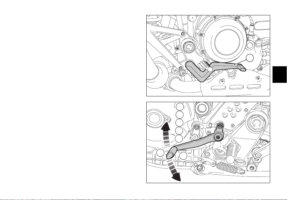
Rear brake pedal (fig. 21) Push down on the pedal (1) to apply the rear brake. The system is hydraulically operated and therfore only a minium pressure is required. fig. 21 Gear change pedal (fig. 22) Gearchange pedal features a center rest position N, with automatic return;…
-
Page 32: Setting The Gear Change And Rear Brake Pedals
Setting the gear change and rear brake pedals The gear change and rear brake pedals can be adjusted to suit the preferred riding position of each rider with respect of the pertinent footpeg. To make these adjustments, follow the procedure described.
-
Page 33
Rear brake pedal (fig. 23a) Loosen check nut (5). Turn pedal travel adjusting screw (6) until pedal is in the desired position. Tighten check nut (5). Work pedal by hand to make sure it has 1.5 — 2 mm free play before brake begins to bite. -
Page 34: Main Components And Devices
MAIN COMPONENTS AND DEVICES Location (fig. 24) 1) Tank filler plug. 2) Pillion seat catch and helmet hooks. 3) Glove compartment catch. 4) Side stand. 5) Front fork adjusters. 6) Rear shock absorber adjusters. 7) Rear-view mirrors.
 Silencer and exhaust pipes. 9) Catalyser (not on USA version).
 -
Page 35: Tank Filler Plug
Tank filler plug (fig. 25) Opening Lift the protection lid (1) and fit the ignition key into the lock. Turn the key clockwise 1/4 turn to unlock. Lift the plug (2, fig. 25a). Closing Refit the plug (2) with the key in it and push it down into its seat.
-
Page 36: Passenger Seat Catch And Helmet Hook
Passenger seat catch and helmet hook Opening (fig. 26) Insert the key in lock (1) and turn it clockwise until you hear the seat catch click in place. OPEN Lift the seat rear end (2) and pull it backward to slide it out from the front supports.
-
Page 37: Glove Compartment Lock
Glove compartment lock To open glove compartment door, insert the key into lock (1) and rotate it counterclockwise until hearing the catch OPEN unlock (fig. 28). Open the door (fig. 28a) to gain access to the glove compartment where the Owner’s manual and the tool kit are (see page 52).
-
Page 38: Side Stand
Side stand (fig. 29) Note It is possible to start the engine with the side stand Important down, if the gearbox is in neutral position. Before lowering the side stand, make sure that the bearing surface is hard and flat. Do not park on soft or pebbled ground or on asphalt melt by the sun heat and similar or the motorcycle may fall over.
-
Page 39: Front Fork Adjusters
Front fork adjusters The front fork used has rebound and compression damping adjuster as well as a spring preload adjuster. This adjustment is done using the outer adjusters: 1) to adjust rebound damping (fig.30); 2) to adjust inner springs preload (fig. 30); 3) to adjust compression damping (fig.
-
Page 40
STANDARD factory setting is as follows: compression: 1 turn; rebound: 11 clicks. To change the preload of the spring inside each fork leg turn the hex. adjusting nut (2) with a 22-mm hexagon wrench. Height (A, fig. 31a) determines preload and may vary from 25 to 10 mm. -
Page 41: Rear Shock Absorber Adjusters
Rear shock absorber adjusters (fig. 32 and 32a) The rear shock absorber features outer adjusters to set the vehicle according to load conditions. The rebound adjuster (1) is on the right-hand side at the bottom shock absorber-to-swingarm fitting. The compression adjuster (2) is on the shock absorber expansion reservoir.
-
Page 42: Rear-View Mirrors Adjustment
Rear-view mirrors adjustment Adjustment is made by simply pushing the mirror in the direction wanted (fig. 33). To lock the mirror in position, tighten the screw at the bottom of the support (fig. 33a). fig. 33 fig. 33a https://www.motorcycle-manual.com/…
-
Page 43: Motorcycle Trim Adjustment
Motorcycle trim adjustment fig. 34 Motorcycle trim is the result of many tests carried out by our engineers in the most different conditions. Changing this parameter is a very delicate operation that might prove dangerous if improperly carried out. Before changing standard setting, it is advisable to measure the reference value (H, fig.
-
Page 44: Directions For Use
Have the service inspections 3) after 2500 km. performed as recommended in the Warranty Card. Failure to comply with these rules will release Ducati Up to 1000 km Motor Holding S.p.A. from any liability whatsoever for During the first 1000 km, keep an eye on the revolution resulting engine damage or shorter engine life.
-
Page 45
After 2500 km After running-in, never exceed the following values during the motorcycle standard use: 10,000 rpm. Strict observance of running-in recommendations will ensure longer engine life and reduce the likelihood of overhauls and tune-ups. 2.500 ÷ +Km 1.000 ÷ 2.500 Km km/h miles km/L… -
Page 46: Pre-Ride Checks
Warning passenger. In case of malfunctioning, do not start the motorcycle and call a DUCATI Dealer or Authorised Workshop. Before riding, perform a thorough check-up on your bike as follows: Fuel level in the tank Check fuel level in the tank.
-
Page 47: Starting The Engine
Starting the engine Warning Before starting the engine, become familiar with the controls you will need to use when riding (see page 10). 1) Move ignition switch to ON (fig. 36). Check that the green pilot light N (8, fig. 5) and the red one fig.
-
Page 48
2) Check that the stop switch (1, fig. 37) is positioned to (RUN), then press the starter button (2). This model is equipped with a servoignition system. To achieve assisted engine starting, press the button (2) and release it immediately. Pressing the button (2) operates automatic engine starting for a maximum period of time that varies depending on engine temperature. -
Page 49: Moving Off
Moving off Braking Slow down in time, shift down to engine-brake first and 1) Disengage the clutch squeezing the control lever. then brake applying both brakes. Pull the clutch lever 2) Push down on gear change lever sharply with the tip before stopping the motorcycle, to avoid sudden engine of your foot to engage the first gear.
-
Page 50: Stopping The Motorcycle
Stopping the motorcycle Important If you let go of the throttle twistgrip, the motorcycle will Do not leave the key turned to P for long periods or slow down gradually and smoothly. Then, shift down the battery will run down. releasing the clutch, and finally change from first to Never leave the ignition key in the switch when you are neutral.
-
Page 51: Refuelling
Refuelling (fig. 38) Max level Never overfill the tank when refuelling. Fuel should never be touching the rim of filler recess. Warning Use low-lead fuel having at least 95 fuel octane rating (see table «Refuelling» page 81). Be sure there is no fuel trapped in the filler recess.
-
Page 52: Tool Kit And Accessories
Tool kit and accessories (fig. 39) In the right-hand fairing there is a compartment that can be accessed after opening the door (see page 37), in this compartment there are: an Owner’s manual; a helmet fastening cable; The tool bag (fig. 40) holds: — box wrench for spark plugs;…
-
Page 53: Main Maintenance Operations
MAIN MAINTENANCE OPERATIONS Removing the fairing Some servicing operations need the motorcycle fairing to be removed. Warning Firmly secure all removed parts properly when refitting them, otherwise some of them might suddenly come off when riding and you may loose control of your motorcycle.
-
Page 54
Mobile headlight fairing Loosen the four screws (1) that secure the mobile headlight fairing to the supports with seal (2). Remove the mobile headlight fairing together with windshield ( fig. 41). To change the windshield, with the suitable torx wrench loosen the screws (3) with nylon washer (4), lock rubber- coated nuts (5) from the inside (fig. -
Page 55
Fixed headlight fairing Undo the six screws (1) securing the inner flange, on either side of the headlight fairing, then pull the inner flange upward and remove it (fig. 42). Note Be careful while removing the flange not to damage the paint of the headlight fairing. -
Page 56
Left side fairing Working on the left side, from inside the fairing, turn counter clockwise by ¼ of a turn the quick-release fitting (1) to release the left side fairing front end (fig. 43). Slide out tab (2) at the frame support to release the left side fairing rear end: it will be easier if you push from the outside on the fairing at the tab (fig. -
Page 57
Before reassembling, make sure that rubber elements (3) and seal (4) are correctly in place on pin (5) on the inside of the fairing (fig. 45). Fit the left side fairing, start from the rear end and fit rubber elements in fuel tank pins (fig. 45a). Push the fairing at pin (5) to be able to engage tab (2) to the pin end. -
Page 58: Checking Brake And Clutch Fluid Level
Brake system If you find exceeding play on brake lever or pedal and brake pads are still in good condition, contact your Ducati Dealer or Authorised Workshop to have the system inspected and any air drained out of the circuit.
-
Page 59
(MAX) 3 mm 3 mm it is possible that there is air in the circuit. Contact your Ducati Dealer or Authorised Workshop to have the system inspected and air drained out. Warning Clutch fluid level will increase as clutch plate friction material wears down. -
Page 60: Checking Brake Pads For Wear
Rear brake pads are to be replaced when friction material is worn down to about 1 mm (fig. 47a). This can be seen through the opening in the caliper halves. Important Have the brake pads replaced at a Ducati Dealer or Authorised Workshop. fig. 47 1 mm fig.
-
Page 61: Lubricating Joints
Ducati Dealer or Authorised Workshop. To prevent these failures it is best to remove the cover by unscrewing the two fastening screws (1, fig.
-
Page 62: Throttle Cable Free Play Adjustment
Throttle cable free play adjustment 1,5 2 mm The throttle twistgrip must have a free play of 1.5 — 2.0 mm (fig. 49) measured at the edge of the twistgrip, at all 1,5 ÷ 2 mm positions of the handlebars. If not so, it is necessary to adjust control travel through the relevant adjusters (1) of the throttle body (fig.
-
Page 63: Charging The Battery
Charging the battery (fig. 51) Before charging the battery, it is best to remove it from the motorcycle. Remove the LH half-fairing (see page 56). Always disconnect the black negative terminal (-) first, and then the red positive terminal (+). Undo the two screws (1) on battery brackets and remove the battery.
-
Page 64: Checking The Drive Chain Tension
If it is not so, it is necessary to change the chain tension. Important 38 ÷ 42 mm Contact an Ducati Dealer or Authorised Workshop to have the drive chain tensioned. fig. 52 Warning Proper tightening of screws (1, fig.
-
Page 65: Chain Lubrication
Chain lubrication The chain fitted on your motorcycle has O-rings that keep dirt out of and lubricant inside the sliding parts. The seals might be irreparably damaged if the chain is cleaned using any solvent other than those specific for O-ring chains or washed using steam or water jets.
-
Page 66: Replacing Headlamp Bulbs
Replacing headlamp bulbs Before replacing a burnt-out bulb, make sure that the new bulb complies with voltage and wattage as specified on page 88, «Electric System», for that lighting device. Always test the new lamp before refitting the parts you have removed.
-
Page 67
Low beam (upper) Disconnect connectors (4) from the clamps on the bulb. Release clip (5) from bulb socket by pushing down and then squeezing its ends (fig. 55). Pull the clip up (5). Remove the burnt-out bulb (6) and replace it with a new one, do not touch the transparent body of the bulb (fig. -
Page 68
Note for the USA version: To remove the low beam bulb (7) disconnect connector (A) from the wiring then turn the bulb counter LOCK LOCK clockwise and extract the burnt-out bulb (fig. 57). Replace it with a new one with the same rating. When refitting, turn the bulb clockwise to lock it on the bulb body. -
Page 69
Remove the burnt-out bulb (10) and replace it with a new one, do not touch the transparent quartz (fig. 59). Parking light Disconnect the connections (11) from terminals (fig. 60). Remove the parking light (12) from its seat and replace it with a new one with the same rating. -
Page 70: Changing The Front Direction Indicators Bulbs
Changing the front direction indicators bulbs Front direction indicators are integrated in the rear-view mirrors. To change the bulb, undo the screw (1) and remove the indicator lens (2) from mirror body (fig. 61). Bulb (3) has a bayonet-type fitting, push it and turn counter clockwise to remove it.
-
Page 71: Changing The Rear Direction Indicators Bulbs
Changing the rear direction indicators bulbs To change rear direction indicator bulbs it is necessary to turn the indicator body (1) by one quarter of a turn, setting it with the lens up, and then remove it from tail light support (fig.
-
Page 72: Changing The Number Plate And Stop Light Bulbs
Changing the number plate and stop light bulbs Loosen the two screws (1) securing tail light support to number plate holder, on the inboard side. Loosen screw (2) and slightly slide out tail light support (fig. 64). Disconnect connector (A) of the rear wiring and remove tail light support (fig.
-
Page 73
Loosen the two self-tapping screws (3) securing body (4) with transparent cover for number plate light. Slide out the body and transparent cover and change bulb (5) for number plate light (fig. 66). To change stop light bulb it is necessary to carry out the procedure described and remove transparent element (6) for stop light from the support. -
Page 74: Beam Setting
Beam setting (fig. 68) When checking beam setting, put the motorcycle upright. Tyres should be inflated at the correct pressure and one person should be sitting astride the motorcycle, keeping it at right angles to its longitudinal axis. Place the motorcycle opposite a wall or a screen, 10 meters apart from it, then draw a horizontal line dictated by headlamp centre and a vertical one in line with the longitudinal axis of motorcycle.
-
Page 75: Tubeless Tyre Pressure
0.2 — 0.3 bar. Important Do not remove or shift the wheel balancing weights. Note If tyres need replacing, contact a Ducati Dealer or Authorised Workshop to make sure wheels are removed and refitted correctly. https://www.motorcycle-manual.com/…
-
Page 76
Minimum tread depth Measure tread depth (S, fig. 70) at the point where tread is most worn. It should not be less than 2 mm and anyway not below the legal limit. Important Visually inspect the tyres at regular intervals for cracks and cuts, especially on the side walls, bulges or large spots that are indicative of internal damage. -
Page 77: Checking Engine Oil Level
Undo the filler plug (2) and top up to correct level. Refit the plug. Important Engine oil and oil filters must be changed by a Ducati dealer or authorized workshop at regular intervals, as fig. 71 specified in the routine maintenance chart (see Warranty Card).
-
Page 78: Cleaning And Replacing The Spark Plugs
This provides a 0,6÷0,7 mm good measure of engine condition. Contact an Ducati Dealer or Authorised Workshop to have the spark plug checked and changed, if needed. Their staff shall check the color of the ceramic insulator on the central electrode: a light brown, even colour is a sign of good engine condition.
-
Page 79: Cleaning The Motorcycle
Ducati Performance. This will protect paintwork and exhaust silencers and adversely affect the operation of let condensate breathe out.
-
Page 80: Technical Data
TECHNICAL DATA Weights Dry weight: 200 Kg Carrying full load: 410 Kg Warning Failure to observe weight limits could result in poor Overall dimensions (mm) (fig. 74) handling and impair the performance of your motorcycle, and you may lose control of the motorcycle. 1462 2130 fig.
-
Page 81
Top-ups Type of fluid cu dm (litres) Fuel tank, including a reserve of 6.5 cu dm (liters) Unleaded fuel 95 fuel octane rating (at least) Lubrication circuit SHELL Advance Ultra 4 Front/Rear brake and clutch circuits Special fluid for hydraulic systems SHELL-Advance Brake DOT 4 Protectant for electric contacts Spray for electric systems… -
Page 82: Engine
Engine Desmodromic timing system (fig. 75) Twin-cylinder 4-stroke «L» 1000cc engine with 1) Opening (or upper) rocker arm. Desmodromic system, with electronic fuel injection, air- 2) Opening rocker arm shim. cooled. 3) Split rings. 4) Closing (or lower) rocker arm shim. Bore: 5) Return spring for lower rocker arm.
-
Page 83: Performance Data
Performance data Spark plugs Maximum speed in any gear should be reached only after Ignition in every cylinder is performed with two spark a correct running-in period with the motorcycle properly plugs. This solution offers smoother combustion and more serviced at the recommended intervals. power, mainly at mid-range.
-
Page 84: Transmission
1st gear 15/37 If you wish to tune up your motorcycle for competitive 2nd gear 17/30 trials, you may refer to Ducati Motor Holding S.p.A. who 3rd gear 20/27 will be glad to provide information about the special ratios 4th gear 22/24 available.
-
Page 85: Brakes
Brakes Rear brake With steel drilled disc in stainless steel. Front brake Disc diameter: Double drilled disc, half-floating 245 mm. Material: Hydraulically operated by a pedal on RH side. steel. Braking surface: Disc diameter: 32 sq cm. 320 mm Make: Hydraulically operated by a control lever on right BREMBO handlebar.
-
Page 86: Frame
Frame Tyres High-strength tubular treillis frame. Steering angle (on each side): Front tyre 35° Tubeless, radial tyre. Size: Steering geometry: 120/70-ZR17. Headstock angle 24° Rear tyre Trail: Tubeless, radial tyre. 109 mm. Size: 180/55-ZR17. Wheels Front wheel Six-spoke light alloy front wheel rim. Dimensions: 3.50×17″…
-
Page 87: Suspensions
Suspensions Available in the following colors: Ducati anniversary red; Front frame: red, black; Hydraulic upside-down fork featuring outer adjusters for rims: metal blue gray. rebound and compression damping and for the preload of the springs inside fork legs. Ducati two-color gray: Stanchion diameter: frame: red, black;…
-
Page 88: Electric System
Electric system Basic electric items are: Twin, stacked halogen headlight made of: Low beam unit — HB3 12V-60W; high beam unit — HB3 12V-60W; parking light unit — 12V-5W. Electrical controls on handlebar. Turn indicators, 12V-10W bulbs. Horn. Stop light switches. Tight-type battery 12V-10 Ah.
-
Page 89
Fuses The main fuse carrier (1, fig. 76) is under left side fairing (see page 56). The fuses can be accessed by removing the safety gaiter. Other than the main fuse carrier, there are other fuses that are positioned at the sides of the battery. Two fuses (2, fig. -
Page 90
Remove the fuse cap (A, fig. 78) to expose the fuse. A blown fuse is identified by the interrupted inner filament (5, fig. 79). Importante Switch the ignition key to OFF before replacing a fuse to avoid possible short circuits. Warning Never use a fuse with a rating other than specified. -
Page 91
Legend of the wiring diagram of electric system/ 29)Speed sensor ignition 30)Side stand switch 31)Neutral switch 1) RH switch 32)Oil pressure switch 2) Key-operated switch 33)Rear stop switch 3) Fuse box 34)Stepper motor 4) Fuses 35)Ignition/injection unit 5) Starter motor 36)Clutch switch 6) Starter contactor 37)Front stop switch… -
Page 92
Wiring Colour Coding Legend of fuse box B Blue W White Pos. El.items Rat. V Violet Key-on 7.5A Bk Black Y Yellow Lights R Red Lb Light Blue Horn,stop,solenoid Gr Gray starter,passing G Green Bn Brown O Orange Grip Heating P Pink Injection ECU power supply… -
Page 93: For United States Of America Version Only
Noise emission warranty Reporting of safety defects Ducati Motor S.p.A. warrants that this exhaust system, at If you believe that your vehicle has a defect which could the time of sale, meets all applicable U.S. EPA Federal cause a crash or could cause injury or death, you should noise standards.
-
Page 94
Tampering warning If you are aware of any of the following symptoms, have Tampering with Noise Control System Prohibited. Federal the vehicle inspected and repaired by your local Ducati Law prohibits the following acts or causing thereof: dealer. (1) the removal or rendering inoperative by any person,… -
Page 95
Riding safety When the roadway is wet, rely more on the throttle to The points given below are applicable for every day control vehicle speed and less on the front and rear brakes. motorcycle use and shoud be carefully observed for safe The throttle should also be used judiciously to avoid and effective vehicle operation. -
Page 96
Vehicle identification number (VIN); Ducati does not manufacture sidecars or trailers and Every Ducati motorcycle is identified by two identification cannot predict the effects of such accessories on handling numbers (see page 9). -
Page 97
Label location (fig. B) fig. B https://www.motorcycle-manual.com/… -
Page 98
ENGINE DISPLACEMENT :992 cc. ENGINE FAMILY : THIS VEHICLE CONFORMS TO U.S. EPA AND CALIFORNIA REGULATIONS APPLICABLE TO MODEL YEAR NEW MOTORCYCLES. EVAP FAMILY : DUCATI Via A. C. Ducati, 3 40132 BOLOGNA HOT AIR INLET ITALY TO HORIZONTAL MANIFOLD TO VERTICAL MANIFOLD… -
Page 99
California evaporation emission system Ducati limited warranty on emission control This system consists of (fig. C): system Ducati North America, Inc., 237 West Parkway, Pompton Plains, New Jersey 07444-1028 warrants that each new Important 1998 and later Ducati motorcycle, that includes as… -
Page 100
30 days. Any replacement part can defects in material or workmanship by an authorized be used in an emergency repair. Ducati will reimburse the Ducati motorcycle dealer at its place of business during owner for the expenses, including diagnosis, not to customary business hours. -
Page 101
Ducati motorcycle for any purpose. The warranty period begins on the date the motorcycle is Some states do not allow the exclusion or limitation of any delivered to an ultimate purchaser. -
Page 102: Routine Maintenance Record
ROUTINE MAINTENANCE RECORD Ducati Mileage Date Service Name 1,000 10,000 20,000 30,000 40,000 50,000 https://www.motorcycle-manual.com/…
|
Detail Specifications: 1253/1253739-multistrada_1000ds.pdf file (10 Nov 2022) |
Accompanying Data:
Ducati Multistrada 1000ds Motorcycle PDF Workshop Manual (Updated: Thursday 10th of November 2022 10:12:27 AM)
Rating: 4.4 (rated by 39 users)
Compatible devices: SPORT TOURING, MONSTER S4, SUPERSPORT CR-SP 900 desmodue, MONSTER 1100 S, 860 GT, 750 Sport Bevel Heaven, Multistrada 950S 2019, Superbike 1199 panigale S.
Recommended Documentation:
Text Version of Workshop Manual
(Ocr-Read Summary of Contents, UPD: 10 November 2022)
-
420, Ducati Multistrada 1000ds A B C D E F G H L M N P Motore Engine sezione / section N 4.4 68 edizione/edition 08-03 Reassembling the heads Replace the head gasket (12) before fitting the complete heads; also check that the locating pins (A) and the bush (B) are in position (Sect. N 5). Slide the complete head on the stud bolts and push it down onto the cylinder. Insert the special washers (20) on …
-
58, Caratteristiche tecniche Technical specification sezione / section C 3 30 A B C D E F G H L M N P edizione/edition 08-03 Filler plug retaining screws 5×0.8 5 Fuel sensor 6×1 10 Front bracket retaining screw (RH/LH) 6×1 10 LOCK 2 Side fairing mounting peg 6×1 1.5 LOCK 2 Breather and drain hose inserts 7×1 2 Roll-over valve retaining screws 5×0.8 2.5 Mudguard retaining screw …
-
164, A B C D E F G H L M N P Comandi — Dispositivi Controls — Devices sezione / section F 2 8 edizione/edition 08-03 Attenzione La casa costruttrice del gruppo rinvio frizione, considerando l’importanza in termini di sicurezza che riveste questo componente, suggerisce di non intervenire in nessun modo all’interno del gruppo rinvio (16). Una revisione non eseguita correttament…
-
499, A B C D E F G H L M N P Motore Engine sezione / section N 9.2 147 edizione/edition 08-03 Chiusura semicarter Installare l’albero rinvio distribuzione (30) nel cuscinetto a rulli (4) sul semicarter lato frizione. Per non danneggiare l’anello di tenuta (14) in corrispondenza dell’albero rinvio distribuzione, è consigliabile proteggere l’estremità filettat…
-
256, Ducati Multistrada 1000ds Mototelaio Frame sezione / section H 5 18 AA B C D E F G H L M N P edizione/edition 08-03 5 — CAVALLETTI 1 Cavalletto laterale 2Vite 3 Piastra supporto 4Vite 5 Interruttore 6Molla 7 Piastrina 8 Perno rotazione 9Dado 10 Perno piastra 5 9 7 6 4 8 3 2 1 5 — STANDS 1 Side stand 2 Screw 3 Support plate 4 Screw 5 Switch 6Spring 7Plate 8Pivot 9Nut 10 Plate pivot Importante I riferimenti in grassett…
-
25, Ducati Multistrada 1000ds A B C D E F G H L M N P Informazioni sul modello 0 Model-specific information 0 DUCmo_MTS#######04_Bb01.book Page 1 Tuesday, August 26, 2003 2:18 PM
… -
292, Impianto di alimentazione / Scarico Fuel system / Exhaust system sezione / section L 7 20 AA B C D E F G H L M N P edizione/edition 08-03 7 — ASPIRAZIONE ARIA 1 Tubo filtro/uscita serbatoio 2 Elemento filtrante 3 Coperchio scatola filtro 4 Colonnetta 5 Scatola filtro aria 6 Presa di pressione 7Vite 8 Gommino 9 Gancio 10 Spina elastica 11 Tubo drenaggio 12 7 3 2 5 8 10 11 4 8 Ve…
-
450, A B C D E F G H L M N P Motore Engine sezione / section N 6.3 98 edizione/edition 08-03 Dopo questa prova, procedere al serraggio definitivo del dado (1), precedentemente montato. Montare sull’ingranaggio (D) l’attrezzo cod. 88713.0137 e bloccarne la rotazione inserendo un perno in uno dei fori di fissaggio blocco motore al telaio. Con chiave dinamometrica bloccare il dado alla …
-
246, A B C D E F G H L M N P Mototelaio Frame sezione / section H 2 8 edizione/edition 08-03 Smontaggio componenti cannotto di sterzo Note Tutti i componenti che sono fissati sulla testa e sulla base di sterzo, compreso i cavi elettrici e le trasmissioni flessibili, possono rimanere montati a condizione che non vadano a interferire con le operazioni da eseguire…
-
120, A B C D E F G H L M N P Uso e manutenzione Use and Maintenance operations sezione / section D 5 44 edizione/edition 08-03 Checking and adjusting timing belt tension Both timing belts can be checked and adjusted using the MATHESIS tester leaving the engine onto the frame. Connect an optical reader to the MATHESIS tester. The green led onto the reader shows correct positioning …
Recommended Instructions:
COBY CS-P34, RCR311BN, RS30, Bi-O Tec


-
0-1dummyheaddummyheadHOW TO USE THIS MANUALHOW TO USE THIS MANUALA Few Words About SafetyService InformationThe service and repair information contained in this manual is intended for use by qualified, professional technicians. Attemptingservice or repairs without the proper training, tools, and equipment could cause injury to you or others. It could also damage thevehicle or create an unsa …
NC700XA 773
-
» » i » i’ ‘l Ji . I . ! i I ;ll .-(.~··.·· :).~ . . ‘y· 1 I ‘I .. ! .1 ,j 1 I ‘; :/ I I I I ~ ·1 : .. ~ «‘ ,, ‘ i ., I : I <:_;/ [ j ! I I …
LB2 1978 128
-
181-1269-14 (English) 7/01/08TMOperator’s ManualTable of ContentsIMPORTANT NOTICE! Safety Definitions…………………………………. iiI. General Safety Precautions …………………………………………………….1II. How to Get Service ………………………………………………………………..4III. Oil and Fuel Specification …
LH195EA 40
-
T6197www.fi sher-price.comPlease keep this instruction sheet for future reference, as it contains important information.Adult assembly is required. Tools required for assembly: Phillips Screwdriver, Hammer and Scrap Block of Wood (not included). Requires three «AA» batteries (included).Age: 2-6 years.Weight limit: 60 lbs (27 kg). …
DORA THE EXPLORER T6197 8
Additional Information:
Popular Right Now:
Operating Impressions, Questions and Answers:

Owner’s manual
DUCATIMULTISTRADA
1000DS
E
1

E
2
Hearty welcome among Ducati fans! Please accept our
best compliments for choosing a Ducati motorcycle. We
think you will ride your Ducati motorcycle for long journeys
as well as short daily trips. Ducati Motor Holding S.p.A.
wishes you smooth and enjoyable riding.
We are steadily doing our best to improve our «Technical
Assistance» service. For this reason, we recommend you
to strictly follow the indications given in this manual,
especially for motorcycle running-in. In this way, your
Ducati motorbike will surely give you unforgettable
emotions. Please contact our authorised service centres
to have your motorcycle repaired or if you simply need
advice.
Enjoy your ride!
Note
Ducati Motor Holding S.p.A. declines any liability
whatsoever for any mistakes incurred in drawing up this
manual. The information contained herein is valid at the
time of going to print. Ducati Motor Holding S.p.A.
reserves the right to make any changes required by the
future development of the above-mentioned products.
E
For your safety, as well as to preserve the warranty,
reliability and worth of your motorcycle, use original Ducati
spare parts only.
Warning
This manual forms an integral part of the motorcycle
and — in the event the motorcycle is resold — must always
be handed over to the new owner.
3

TABLE OF CONTENTS
General 6
Warranty 6
Symbols 6
E
Useful information for safe riding 7
Carrying the maximum load allowed 8
Identification data 9
Controls 10
Position of motorcycle controls 10
Instrument panel 11
LCD unit functions 12
LCD — Parameter setting/display 14
Backlighting function 21
Pilot lights brightness function 21
Auto-off headlight function 21
The immobilizer system 21
Keys 22
Code card 23
Procedure to disable immobilizer engine block through
throttle twistgrip 24
Duplicate keys 25
Ignition switch and steering lock 26
4
Left switch 27
Clutch lever 28
Right switch 29
Throttle twistgrip 29
Front brake lever 30
Rear brake pedal 31
Gear change pedal 31
Setting the gear change and rear brake pedals 32
Main components and devices 34
Location 34
Tank filler plug 35
Passenger seat catch and helmet hook 36
Glove compartment lock 37
Side stand 38
Front fork adjusters 39
Rear shock absorber adjusters 41
Rear-view mirrors adjustment 42
Motorcycle trim adjustment 43
Directions for use 44
Running-in recommendations 44
Pre-ride checks 46
Starting the engine 47
Moving off 49
Braking 49
Stopping the motorcycle 50
Parking 50
Refuelling 51
Tool kit and accessories 52

Main maintenance operations 53
Removing the fairing 53
Checking brake and clutch fluid level 58
Checking brake pads for wear 60
Lubricating joints 61
Throttle cable free play adjustment 62
Charging the battery 63
Checking the drive chain tension 64
Chain lubrication 65
Replacing headlamp bulbs 66
Changing the front direction indicators bulbs 70
Changing the rear direction indicators bulbs 71
Changing the number plate and stop light bulbs 72
Beam setting 74
Tubeless tyre pressure 75
Checking engine oil level 77
Cleaning and replacing the spark plugs 78
Cleaning the motorcycle 79
Storing the bike away 79
Important notes 79
Technical data 80
Overall dimensions 80
Weights 80
Engine 82
Timing system 82
Performance data 83
Spark plugs 83
Exhaust system 83
Transmission 84
Brakes 85
Frame 86
Wheels 86
Tyres 86
Suspensions 87
Available in the following colors: 87
Electric system 88
For United States of America version Only 93
Routine maintenance record 102
E
5

GENERAL
Warranty
In your own interest, and in order to guarantee product
reliability, you are strongly advised to refer to a Ducati
E
Dealer or Authorised Workshop for any servicing requiring
particular technical expertise. Our highly skilled staff have
access to the implements required to perform any
servicing job at best, and use Ducati original spare parts
only as the best guarantee for full interchangeability,
smooth running and long life.
All Ducati motorcycles come with a «Warranty Card». The
warranty does not apply to the motorcycles used in
competitions. No motorcycle part may be tampered with,
altered, or replaced with parts other than original Ducati
spare parts during the warranty period, or the warranty will
be automatically invalidated.
6
Symbols
Ducati Motor Holding S.p.A. advises you to read this
booklet carefully so as to become familiar with your
motorcycle. In case of any doubts, please call a Ducati
Dealer or Authorised Workshop. The information
contained herein will prove useful on your trips — and
Ducati Motor Holding S.p.A. wishes you smooth,
enjoyable riding — and will help you keep the performance
of your motorcycle unchanged for a long time.
Warning
Failure to comply with these instructions may put you
at risk and lead to severe injury or death.
Important
Possibility of damaging the motorcycle and/or its
components.
Note
Additional information on the job being carried out.
The terms right and left are referred to the motorcycle
viewed with respect to the direction of travel.
Useful information for safe riding
Warning
Read this section before riding your motorcycle.
Accidents are frequently due to inexperience. Always
make sure you have your licence with you when riding;
you need a valid licence to be entitled to ride your
motorcycle.
Do not lend your motorcycle to inexperienced riders or
who do not hold a valid licence.
Both rider and pillion passenger must always wear a
safety helmet.
Wear proper clothing, with no loose items or accessories
that may become tangled in the controls or limit your zone
of vision.
Never start or run the engine indoors. Exhaust gases are
poisonous and may lead to loss of consciousness or even
death within a short time.
Both rider and pillion passenger should keep their feet on
the footpegs when the motorcycle is in motion.
Always hold handlebar firmly with both hands so you will
be ready for sudden changes of direction or in the road
surface. The pillion passenger should always hold on to
the suitable grab handle at the rear seat with both hands.
Ride within the law and observe national and local rules.
Always respect speed limits where these are posted.
However, always adjust your speed to the visibility, road
and traffic conditions you are riding in.
Always signal your intention to turn or pull to the next lane
in good time using the suitable turn indicators.
Be sure you are clearly visible and do not ride within the
blind spot of vehicles ahead.
Be very careful when tackling road junctions, or when
riding in the areas near exits from private grounds, car
parks or on slip roads to access motorways.
Always turn off the engine when refuelling.
Be extremely careful not to spill fuel on the engine or on
the exhaust pipe when refuelling.
Do not smoke when refuelling.
While refuelling, you may inhale noxious fuel vapours.
Should any fuel drops be spilled on your skin or clothing,
immediately wash with soap and water and change your
clothing.
Always remove the key when you leave your motorcycle
unattended.
The engine, exhaust pipes, and mufflers stay hot for a long
time.
Warning
The exhaust system might be hot, even after engine
is switched off; pay particular attention not to touch
exhaust system with any body part and do not park the
vehicle next to inflammable material (wood, leaves etc.).
Park your motorcycle where no one is likely to hit it and
use the side stand.
Never park on uneven or soft ground or your motorcycle
may fall over.
E
7

Carrying the maximum load allowed
Your motorcycle is designed for long-distance riding,
carrying the maximum load allowed in full safety.
Even weight distribution is critical to preserving these
safety features and avoiding trouble when performing
sudden manoeuvres or riding on bumpy roads.
Information about carrying capacity
The total weight of the motorcycle in running order
including rider, pillion passenger, luggage and additional
accessories should not exceed 410 Kg.
E
8
Arrange your luggage or heavy accessories in the lowest
possible position and close to motorcycle centre.
Be sure to secure the luggage to the supports provided on
the motorcycle as firmly as possible. Improperly secured
luggage may affect stability.
Never fix bulky or heavy objects to the handlebar or to the
front mudguard as this would affect stability and cause
danger.
Do not insert any objects you may need to carry into the
gaps of the frame as these may foul moving parts.
Make sure the tyres are inflated to the proper pressure
indicated at page 75 and that they are in good condition.
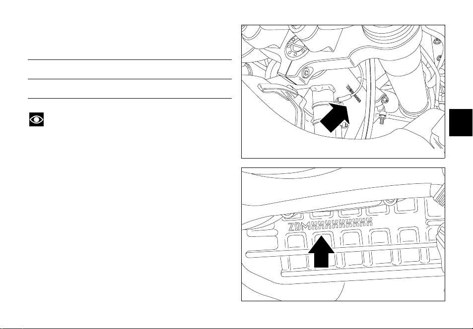
Identification data
All Ducati motorcycles have two identification numbers,
for frame (fig. 1) and engine (fig. 2).
Frame number
Engine number
Note
These numbers identify the motorcycle model and
should always be indicated when ordering spare parts.
E
fig. 1
fig. 2
9
CONTROLS
Warning
This section details the position and function of all the
controls you need to drive your motorcycle. Be sure to
E
read this information carefully before you use the controls.
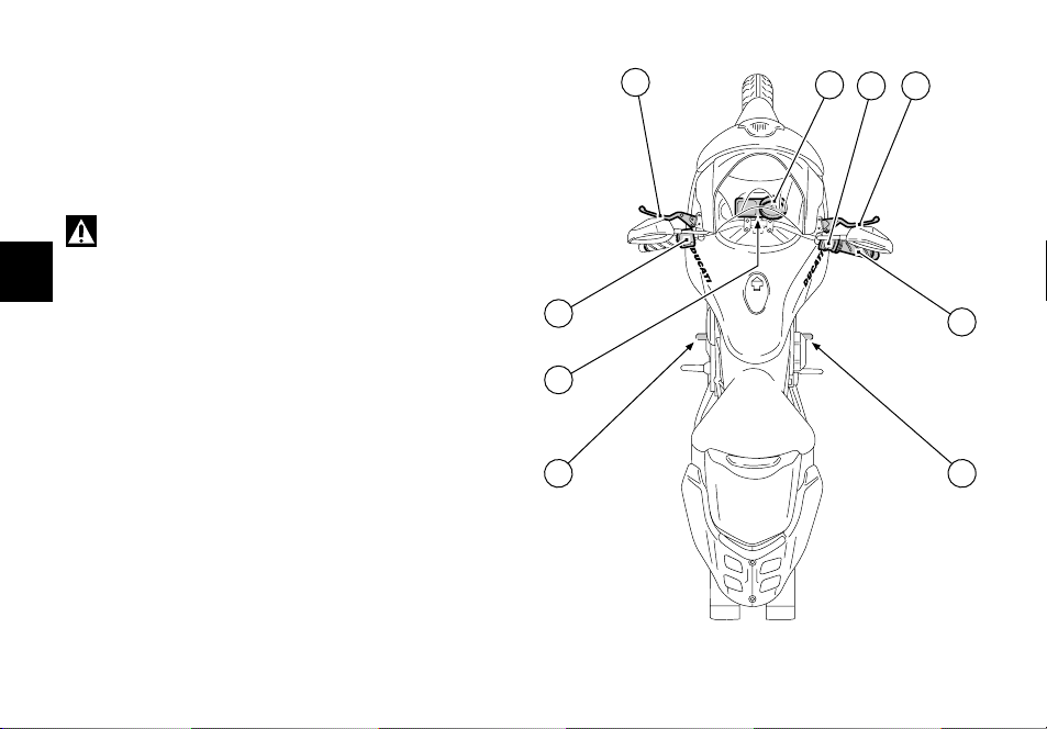
Position of motorcycle controls (fig. 3)
1) Instrument panel.
2) Key-operated ignition switch and steering lock.
3) Left switch.
4) Right switch.
5) Throttle twistgrip.
6) Clutch lever.
7) Front brake lever.
 Rear brake pedal.
9) Gear change pedal.
10
6
3
1
74
5
2
8 9
fig. 3
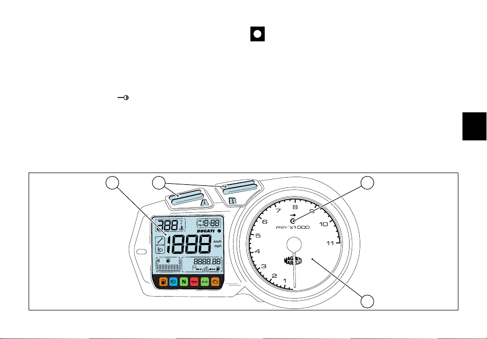
Instrument panel
1) LCD, (see page 12).
2) Control buttons A and B.
Buttons used to display and set instrument panel
parameters.
3) Immobilizer IMMO indicator (amber).
The indicator stays on in case of wrong key code or key
code not recognised; it flashes in case an immobilizer
system warning was reset with the procedure to override
the immobilizer with the throttle twistgrip (see page 24).
Important
The instrument panel allows to making diagnosis on
the electronic injection/ignition system.
These menus are for the trained personnel only; do not
use them for any reason. Should you accidentally enter
this function, turn the key to OFF and contact an
authorised Ducati Service Center for the necessary
inspections.
4) Revolution counter (rpm).
Shows the engine rotation speed/minute.
E
21
km/h
miles
mph
km/L
mpgal
3
4
fig. 4
11

LCD unit functions
Warning
Stop the motorcycle before using the instrument
panel controls. Never operate the instrument panel
controls while riding.
1) Oil temperature warning light.
This function indicates engine oil temperature.
E
Important
Never use the vehicle when the temperature reaches
max. value or the engine might damage.
2) Clock.
3) Tachometer.
This function indicates vehicle speed.
12
4) Auxiliary display.
This function indicates odometer, trip meter, average
speed, instant fuel consumption, average fuel
consumption, fuel used, range and residual fuel quantity,
in this sequence.
5) EOBD light (amber).
When on, this light is used by the control unit to signal the
presence of errors and the consequent engine disabling.
It is also used as a reference light during the immobilizer
overriding procedure with the throttle twistgrip.
If there are no errors, the light should turn on when the
ignition switch is turned ON and should go off after a few
seconds (usually 1.8 — 2 seconds).
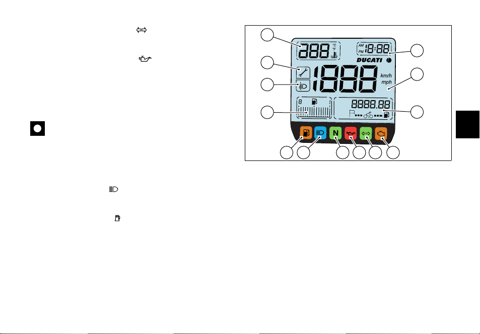
6) Indicators repeater light (green).
Comes on and flashes when a turn indicator is on.
7) Engine oil pressure light (red).
Comes on when engine oil pressure is too low. It briefly
comes on when the ignition is switched to ON and
normally goes out a few seconds after engine starts.
It may shortly come on when the engine is very hot,
however, it should go out as the engine revs up.
Important
If this light (7) stays on, stop the engine or it may
suffer severe damage.
Neutral light N (green).
Comes on when in neutral position.
9) High beam light (blue).
Comes on when high beam is on.
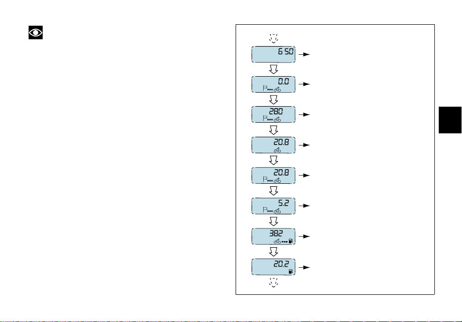
10)Fuel warning light (yellow).
Comes on when there are about 6.5 liters fuel left in the
tank.
11) Fuel Display.
This function indicates the quantity of fuel in the fuel tank.
When the last bar stays on (flashing), the low fuel light (10)
comes on.
1
2
13
3
12
km/h
miles
mph
11
km/L
mpgal
9
67810
4
5
fig. 5
12)Beam vertical adjustment indicator.
The pilot light comes on to signal that the user has entered
the beam vertical setting mode.
13)Service warning.
The light comes on to signal that the vehicle has covered
the distance corresponding to a Scheduled Maintenance
interval. The light keeps flashing until the vehicle has
travelled 50 km after hitting the service interval. Then it
stays on permanently. The system shall be reset by the
DUCATI Authorised Service Center that has serviced the
vehicle.
13
E
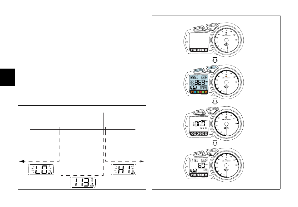
LCD — Parameter setting/display
When turning the key from OFF to ON (Key-ON) the
instrument panel carries out a Check of the whole
instruments: indexes, displays and pilot lights (see fig. 6).
Oil temperature (fig. 7)
This function indicates engine oil temperature.
When temperature is below 40 °C/104 °F a flashing «LO»
message is displayed.
When oil temperature is between 40 °C/104 °F and 170
°C/338 °F temperature measurement is displayed.
E
When oil temperature goes over 170 °C/338 °F a flashing
«HI» message is displayed.
40 ˚C/104 ˚F 170 ˚C/338 ˚F
OFF
km/h
miles
mph
km/L
mpgal
CHECK 1
14
39 ˚C/102 ˚F
171 ˚C/340 ˚F
fig. 7
CHECK 2
km/h
ON
fig. 6
Note
If the sensor measuring the temperature is
disconnected, a string of dashes «- — -» is displayed.
Clock setting function
Hold down button (A, see page 11) for 2 seconds, the
wording AM begins to flash. If button (B) is pressed again,
PM begins to flash; press button (B) to go back to previous
step. Press button (A) to confirm and start setting hours
that shall begin to flash.
Use button (B) to change hour value. If button (B) is
pressed for more than 5 seconds, fast scroll is activated.
Press button (A) to confirm and start setting minutes. Use
button (B) to set minutes. Press button (A) to confirm and
exit clock setting mode and go back to normal operation.
km
miles
km
miles
km/h
mph
km/L
mpgal
ODOMETER
TRIP METER
AVERAGE SPEED
INSTANT FUEL CONSUMPTION
E
Auxiliary display functions (fig.
Press button (B) with the key on ON to scroll down the
following functions, in sequence:
— Odometer
-TRIP meter
— Average speed
— Instant fuel consumption
— Average consumption
— Fuel used
-Range
-Digital fuel level indication
km/L
mpgal
L
gal
km
miles
L
gal
AVERAGE CONSUMPTION
FUEL USED
RANGE
DIGITAL FUEL LEVEL INDICATION
fig. 8
15
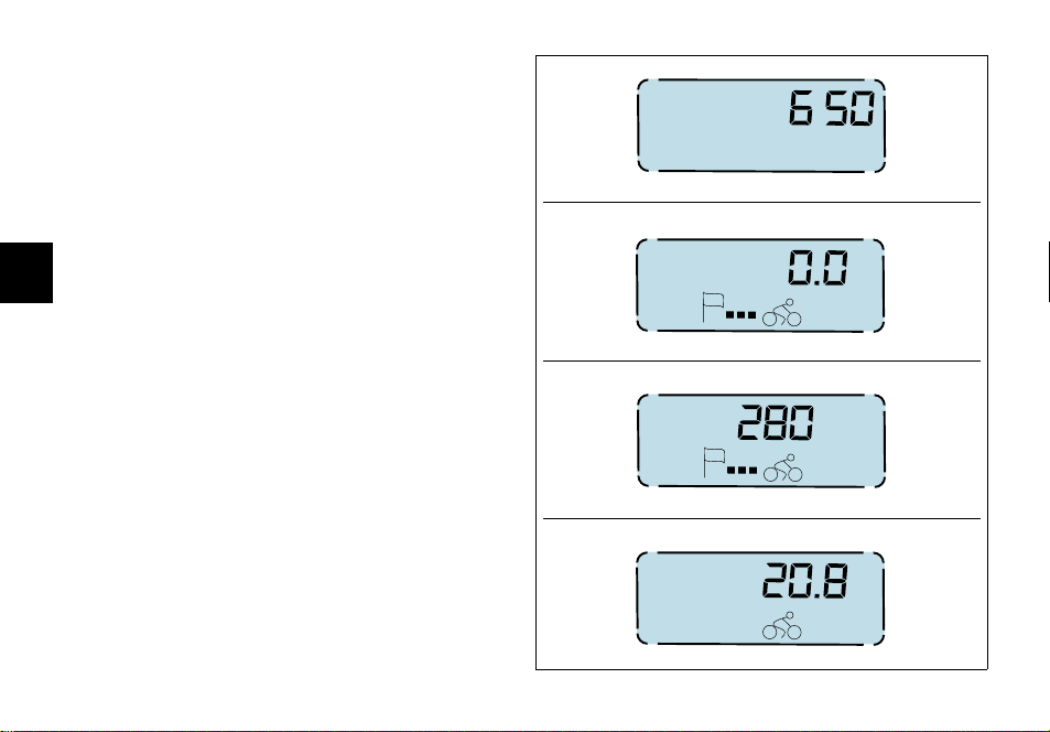
«Odometer» indication (fig. 9)
Indicates total distance covered by the vehicle.
«TRIP meter» indication
This function indicates the distance covered since the
meter was last reset. It is possible to reset this indication
by entering the relevant function and holding down button
(A, see page 11), for at least 2 seconds. When a value of
9999.9 km (or miles) is reached, the display will
E
automatically reset.
«Average speed» indication
This function indicates vehicle average road speed.
Average speed calculation is based on the distance
travelled since the «TRIP meter» was last reset.
«Instant fuel consumption» indication
This function indicates the instant consumption of the
vehicle when in motion. When the vehicle is stopped with
engine running, a string of dashes is displayed «- — . -«. With
vehicle stopped and engine off «0.0» is displayed.
16
km
miles
km
miles
km/h
mph
km/L
mpgal
fig. 9
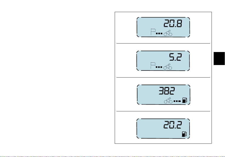
«Average consumption» indication (fig. 10)
This function indicates the vehicle average consumption
when in motion. The calculation is based on the distance
travelled since the «TRIP meter» was last reset. When the
vehicle is stopped, either with the engine off or running,
the last value stored is displayed until indication is
refreshed.
«Fuel used» indication
This function indicates the fuel used by the vehicle to travel
the distance. The calculation is based on the distance
travelled since the «TRIP meter» was last reset. When
indication exceeds 9999.9 liters (2201.9 Imp. gal. — 2641.9
US gal.), the display shows a string of dashes «- — . -«.
km/L
mpgal
L
gal
km
miles
L
gal
E
fig. 10
17

«Range» indication
This function indicates how far the vehicle can travel using
the fuel left in the tank. When this display function is not
selected, the display automatically switches to «Range»
indication as soon as the LOW FUEL LIGHT (10, fig. 5)
comes on and the display shows a string of dashes «- — . -»
and the indication for 10 seconds. Range indication is then
turned on automatically every 60 seconds while the low
fuel light stays on.
When the vehicle is stopped, either with the engine off or
running, the last value stored is displayed until indication is
E
refreshed.
Note
The value is refreshed every10 seconds, the
tolerance is 0.5 km.
«Digital fuel level» indication
This function indicates how much fuel is left in the fuel
tank.
When the LOW FUEL LIGHT (10, fig. 5) comes on, the
display shows a string of dashes «- — . -» and the fuel pump
symbol begins to flash.
Note
This vehicle is equipped with a long fuel tank, fuel
level indication might be slightly altered when riding up- or
downhill for a certain period.
18
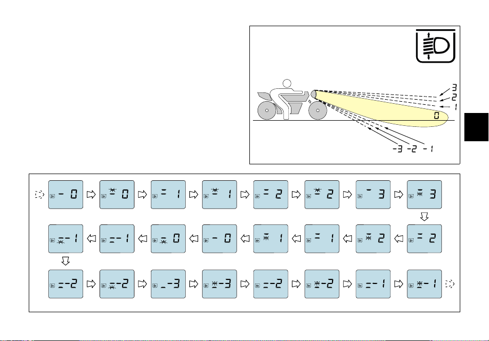
Beam vertical adjustment (fig. 11)
This function allows headlight beam height setting.
To enter this function, hold down button (B, see page 11)
and turn the key to ON; the display shows a value (fig. 11a)
corresponding to beam position and the pilot light on the
display (12, fig. 5) comes on.
Use buttons (A) and (B), respectively, to lower or raise the
beam. Range available is from position «3» (max. beam
height) to position «-3» (min. beam height).
Turn the key to OFF to exit the function. While exiting
setting mode, the selected beam position is stored.
BBBA
AB B B
E
fig. 11
AAAA
fig. 11a
19
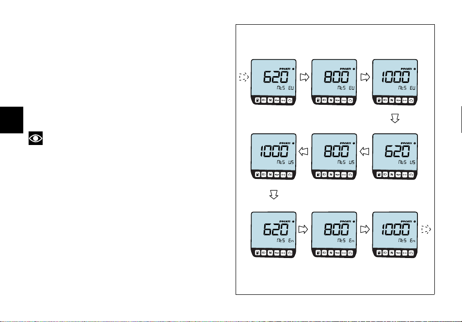
Special selection function: vehicle model and unit of
measurement (fig. 12)
The control unit automatically informs the instrument
panel about the vehicle model and unit of measurement to
be displayed; hold down buttons (A) and (B) and turn
ignition switch from OFF to ON to force the system and
change these parameters. The display shows vehicle
model and version in flashing mode. Press button (B) to
display in sequence all possible settings. To save the
setting chosen hold down button (A) for at least 5
seconds, until OFF is displayed, then turn the key to OFF.
E
Note
When this function is activated, vehicle ignition is
inhibited.
20
fig. 12

Backlighting function
Instrument panel backlighting is active only if the parking
light or the low/high beam is on.
In this case the instrument panel automatically turns on or
off the backlighting, thanks to some sensors measuring
light condition and ambient temperature.
Pilot lights brightness function
This function is active only if the parking light or the low/
high beam is on.
Pilot lights brightness is automatically adjusted by the
instrument panel according to the outer light measured.
Auto-off headlight function
This function allows you to reduce current consumption from
the battery, by automatically managing headlight switching-off.
The device is enabled in two instances:
— If the key is turned from OFF to ON and no attempt is
made to start the engine. After 60 seconds, the
headlight is switched off and will be turned on only
upon the following Key-ON.
— After having used the bike, with headlight on, if the
engine is stopped via the ENGINE KILL switch (2, fig.
19), after 60 seconds from engine stop, the headlight is
turned off and will be turned on upon the following
engine start-up.
Note
While starting the engine, the system switches off
the headlight and turns it back on again after engine has
started, or anyway when the button (3, fig. 19) is released.
The immobilizer system
For improved anti-theft protection, the motorcycle is
equipped with an IMMOBILIZER, an electronic system
that inhibits engine operation whenever the ignition switch
is turned off.
Accommodated in the handgrip of each ignition key is an
electronic device that modulates an output signal. This
signal is generated by a special antenna incorporated in the
switch when the ignition is turned on and changes every
time. The modulated signal acts as a «password» and tells
the CPU that an «authorised» ignition key is being used to
start up the engine. When the CPU recognises the signal,
it enables engine start-up.
21
E
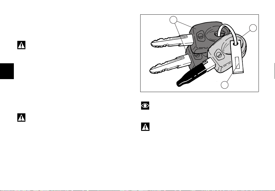
Keys (fig. 13)
The Owner receives a set of keys comprising:
— 1 RED key (A)
— 2 BLACK keys (B)
Warning
Red key has a rubber cover for preserving it in perfect
conditions and avoiding contact with other keys. Never
remove this protection unless really needed.
The black keys are regular ignition keys and are used to:
E
— start up the engine
— open the fuel tank filler plug
— open the seat lock
— release the pillion seat lock.
The red key performs the same functions as the black
keys, and is also used to wipe off and re-program other
black keys, if needed.
Warning
Any important shock might damage the electronic
components fitted into the key.
22
B
A
1
Note
The three keys have a small plate (1) attached that
reports their identification number.
Warning
Keep the keys in different places. Store the plate (1)
and the red key in a safe place.
It is also recommended to use always the same black key
to start the bike.
fig. 13
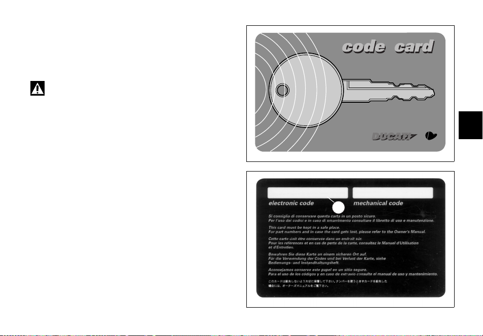
Code card
A CODE CARD (fig. 14) is supplied together with the keys,
it indicates the electronic code (A, fig. 15) to be used in
case the engine is disabled and will not start up after the
key-ON.
Warning
Keep the CODE CARD in a safe place. However, it is
advisable to keep the electronic code printed on the CODE
CARD handy when you ride your motorcycle, in case it is
necessary to remove engine block through the procedure
that uses the throttle twistgrip (see page 24).
In case of faulty immobilizer system, this procedure gives
the chance to disable «engine block» function -signalled by
the orange EOBD warning light (5, fig. 5).
E
fig. 14
A
fig. 15
23

Procedure to disable immobilizer engine block
through throttle twistgrip
1) Turn the key to ON and fully open throttle. Keep it
open. The EOBD warning light turns off after 8
seconds.
2) Release the throttle as soon as the EOBD warning
light turns off.
3) EOBD pilot light will flash. Count a number of flashes
corresponding to the first figure of the code printed on
the CODE CARD, open full throttle and keep the
position for 2 seconds, then release. In this way the
E
input of one figure is acknowledged, EOBD pilot light
comes on and stays on for 4 seconds. Carry out the
same procedure for the following figures of the code.
Failure to do so will cause the EOBD pilot light to flash
20 times, then it will stay on. This means that the
procedure has been aborted. It will be necessary to
turn the key to OFF and restart from point 1.
4) Repeat operations described in point 3 up to the last
figure of the code.
24
5) Release the throttle twistgrip, if the code is correct the
following two conditions may occur:
A) the EOBD warning light shall flash signalling that
engine block has been disabled. The warning light turns
off after 4 seconds or if engine revolutions go over the
limit value of 1000 rpm.
B) the IMMO light (3, fig. 4) flashes until engine rpm
get above 1000 rpm, or until engine is re-started.
6) If the code is NOT correct, the EOBD warning light
and the IMMO light stay on and it is then possible to
repeat the procedure, starting from point 2, as many
times as necessary (infinite).
Note
Should the throttle twistgrip be released before the
set time, the warning light turns on again. It is then
necessary to bring the key to OFF and restart the
procedure from point 1.
Operation
When the ignition key is turned to OFF, the immobilizer
inhibits engine operation.
When the ignition key is turned back to ON to start the
engine (Key-ON), the following happens:
1) if the CPU recognised the code, the IMMO light on the
instrument panel will flash briefly. This means that the
immobilizer system has recognised the key code and
enabled engine ignition. When you press the start
button, the engine will start up.
2) If the IMMO light stays on, it means that the code has
not been recognised. When this is the case, turn the
ignition key back to OFF and then to ON again. If the
engine still does not start, try with another black key.
If the other key does not work out either, contact the
DUCATI Service network.
3) Should the IMMO pilot light still be flashing, it means
that an immobilizer system fault was reset (e.g. with
the overriding procedure through throttle grip).
Important
Use only one key during the procedure. Failure to do
so might prevent the system from recognizing the code of
the key in use.
Duplicate keys
If you need any additional key, contact the DUCATI Service
network with all the keys you have left and your CODE
CARD.
DUCATI Service will program new keys and re-program
your original keys, up to 8 keys in total.
You may be asked to identify yourself as the legitimate
owner of the motorcycle. Be sure you have any
documents you might need to this end ready.
The codes of any keys not submitted will be wiped off
from the memory to make those keys unserviceable in
case they have been lost.
Note
If you sell your motorcycle, do not forget to give all
keys and the CODE CARD to the new owner.
25
E
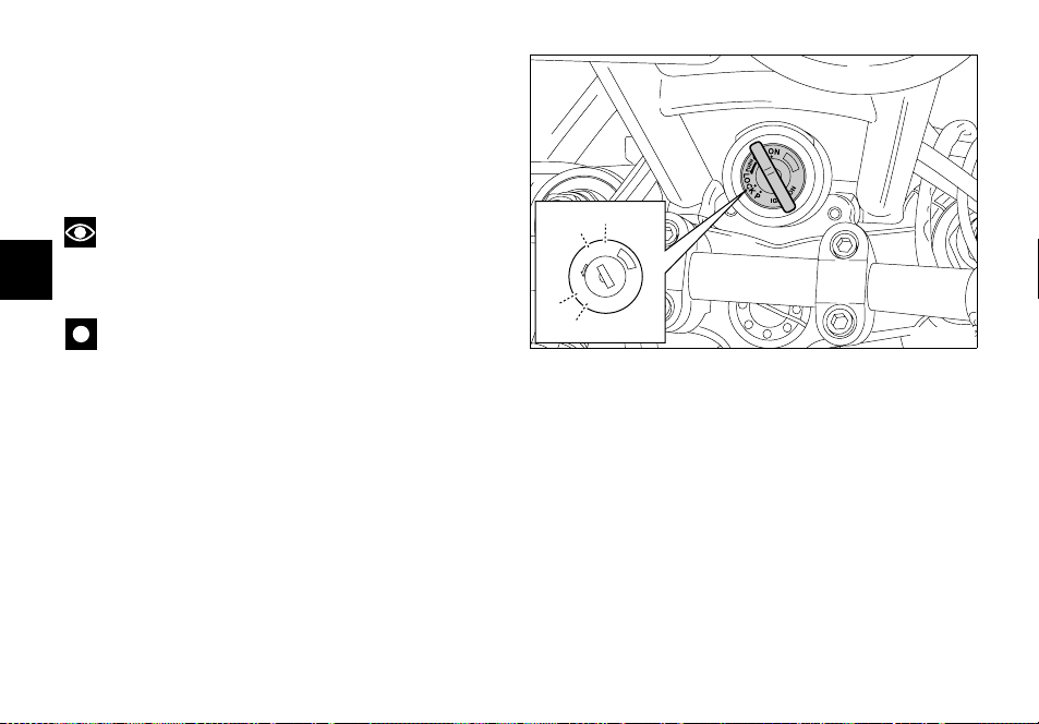
Ignition switch and steering lock (fig. 16)
It is located in front of the steering head and has four
positions:
A) ON: lights and engine on;
B) OFF: lights and engine off;
C) LOCK: steering is locked;
D) P: parking light is ON and steering is locked.
Note
To move the key to the last two positions, press it
down before turning it. Switching to (B), (C) and (D), you
E
will be able to take the key out.
Important
The motorcycle is equipped with an energy-saving
CPU. If the key stays ON for a long period but the ignition
button is not pressed within 15 seconds, the CPU will stop
operating to avoid current absorption. To restore the
system move the key to OFF and then to ON again.
26
A
B
N
O
F
F
O
H
S
U
P
LOCK
P
C
IGNITION
D
fig. 16
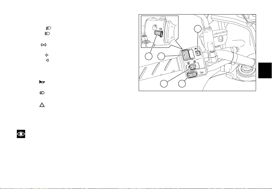
Left switch (fig. 17)
1) Dip switch, light dip switch, two positions:
— position = low beam on;
— position = high beam on.
2) Switch = 3-position turn indicator:
— centre position = OFF;
— position = left turn;
— position = right turn.
To reset turn indicators, push in when switch is back to
central position .
5
4
1
E
3) Button = warning horn.
4) Button = high-beam flasher.
5) Button = Emergency stop flashers
Press this button to turn on all direction indicators at
the same time.
Press it again to turn them off.
Note
When devices (1), (2), (4) and (5) are activated, the
relevant pilot lights on the instrument panel turn on (see
page 13).
32
fig. 17
27
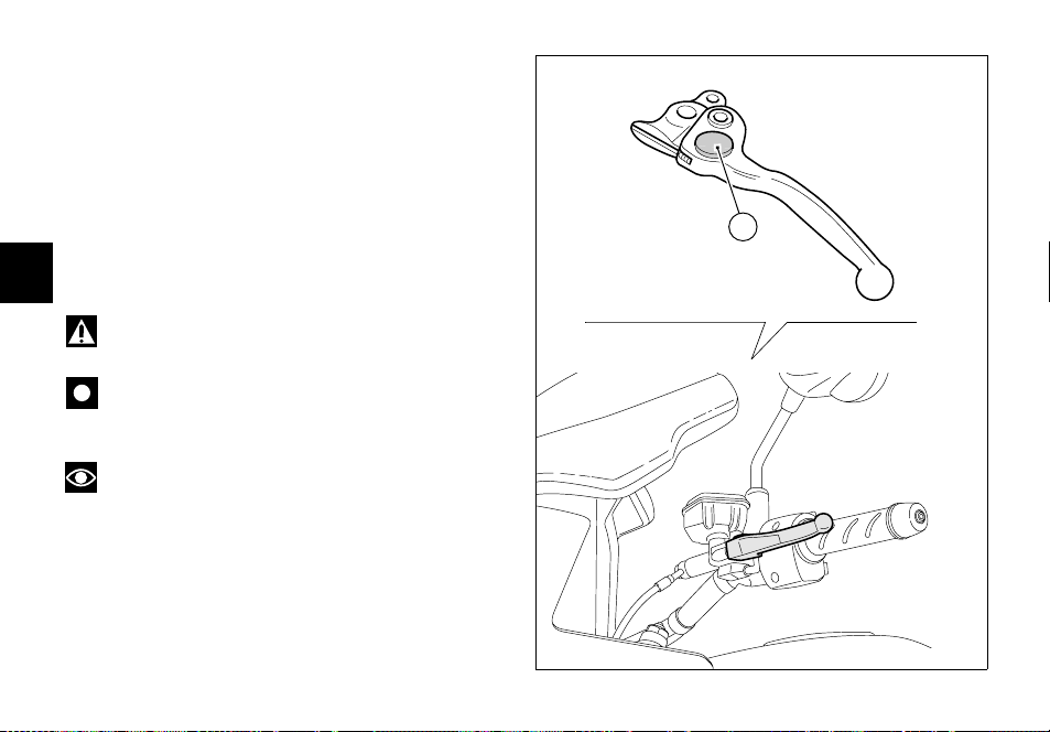
Clutch lever (fig. 18)
Lever (1) disengages the clutch. It features a dial adjuster
(2) for lever distance from the twistgrip on handlebar.
To set lever distance from twistgrip, push lever (1) fully
forward and turn the dial adjuster (2) to one of its four
positions. Remember that position no. 1 gives maximum
distance between lever and twistgrip, whereas lever and
twistgrip are closest when adjuster is set to position no. 4.
When you pull in the lever (1), you will disengage the
engine from the gearbox and therefore from the driving
wheel. Using the clutch properly is essential to smooth
E
riding, especially when moving off.
Warning
Set clutch lever when motorcycle is stopped.
Important
Using the clutch properly will avoid damage to
transmission parts and spare the engine.
Note
It is possible to start the engine with side stand fully
down and the gearbox in neutral. When starting the bike
with a gear engaged, pull the clutch lever (in this case the
side stand must be up).
28
4
3
1
2
2
fig. 18
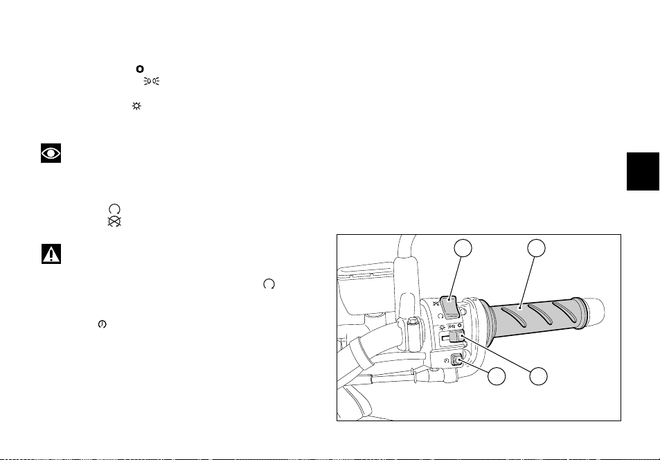
Right switch (fig. 19)
1) Switch, light switch, three positions:
— right position = lights off;
— centre position = front and rear parking lights,
— number plate and instrument panel lights on;
— left position = headlight, front and rear parking
lights, number plate and instrument panel lights on.
Note
This device is not fitted on the Australia and Japan
versions.
2) Switch for engine stop, two positions:
— position (RUN) = run.
— position (OFF) = stop.
Throttle twistgrip (fig. 19)
The twistgrip (4) on the right handlebar opens the throttles.
When released, it will spring back to the initial position
(idling speed).
E
Warning
This switch is mainly intended for use in emergency
cases when you need to stop the engine quickly. After
stopping the engine, return the switch to the position
to enable starting.
3) Button = engine start.
2 4
3
1
fig. 19
29
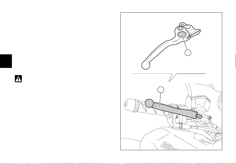
Front brake lever (fig. 20)
Pull in the lever (1) towards the twistgrip to operate the
front brake. The system is hydraulically operated and you
just need to pull the lever gently.
The control lever features a dial adjuster (2) for lever
distance from the twistgrip on handlebar.
To adjust, keep lever (1) completely extended, turn knob
(2) and set it to one of the four available positions.
Consider that:
position no. 1 corresponds to the maximum distance
E
between lever and twistgrip, while position no. 4
corresponds to the minimum distance.
Warning
Front brake lever adjustment is to be carried out
when the bike is stopped.
30
4
3
1
2
2
1
fig. 20
Rear brake pedal (fig. 21)
Push down on the pedal (1) to apply the rear brake. The
system is hydraulically operated and therfore only a
minium pressure is required.
1
E
fig. 21
Gear change pedal (fig. 22)
Gearchange pedal features a center rest position N, with
automatic return; this condition is signalled by the pilot
light N (8, fig. 5) on the instrument panel turning on.
The pedal can be moved:
down = push down on the pedal to engage 1st gear and to
shift down. The N light will go out.
up = lift the pedal to engage the 2nd gear and then the 3rd,
4th, 5th and 6th gear.
Each time you move the pedal you will engage the next
gear.
6
5
4
3
2
N
1
fig. 22
31
 Loading…