Introduction
3
How to Use this Manual
4
Repair Procedures
4
Identification Information Engine Serial Number
6
General Repair Instructions
6
Precautions for Vehicles Equipped with a Catalytic Converter
8
Abbreviations Used in this Manual
9
Engine Mechanical
10
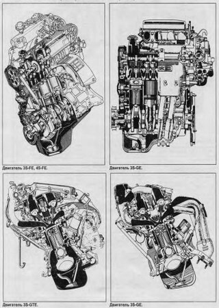
Description (5S-FE)
11
Description (3S-GE and 3S-GTE)
13
Troubleshooting
16
Engine Overheating
16
Hard Starting
16
Rough Idling
16
Engine Hesitates/Poor Acceleration
17
Engine Dieseling
18
After Fire, Backfire
18
Excessive Oil Consumption
18
Excessive Fuel Consumption
19
Unpleasant Odor
19
Engine Tune-Up
20
Inspection of Air Filter
20
Inspection of High-Tension Cords
20
Inspection and Adjustment of Spark Plugs (Conventional Type Only)
20
Inspection and Adjustment of Alternator Drive Belt (5S-FE)
21
Inspection and Adjustment of Alternator Drive Belt (3S-GE and 3S-GTE)
21
Inspection and Adjustment of Valve Clearance (5S-FE)
22
Adjusting Shim Selection Using Chart
24
Intake
24
Exhaust
25
Inspection and Adjustment of Valve Clearance (3S-GE and 3S-GTE)
26
Adjust Valve Clearance
27
Inspection and Adjustment of Ignition Timing (5S-FE)
31
Warm up Engine
31
Connect Tachometer
31
Further Check Ignition Timing
31
Inspection and Adjustment of Ignition Timing (3S-GE and 3S-GTE)
32
Inspection and Adjustment of Idle Speed (5S-FE)
33
Initial Conditions
33
Adjust Idle Speed
33
Further Check Idle Speed
34
Inspection of Idle Speed (3S-GE and 3S-GTE)
34
Inspection of Acoustic Control Induction System (ACIS) (3S-GE)
34
Inspection of TOYOTA-Variable Induction System (T-VIS) (3S-GTE)
35
Connect Vacuum Gauge
35
Inspect T-VIS Operation
35
Idle HC/CO Concentration Check Method (W/Twc)
36
Check Oxygen Sensor Operation
36
Check HC/CO Concentration at Idle
37
Idle Co Concentration Check and Adjustment Method (W/O TWC)
38
Compression Check
40
Check Cylinder Compression Pressure
40
Timing Belt (5S-FE)
42
Components
42
Removal of Timing Belt
42
Remote No.2 Timing Belt Cover
43
Set No.1 Cylinder to Tdc/Compression
43
Remove Timing Belt from Camshaft Timing Pulley
43
Remove Camshaft Timing Pulley
44
Remove Crankshaft Pulley
44
Remove No.1 Timing Belt Cover
45
Remove Timing Belt Guide
46
Remove No.1 Idler Pulley and Tension Spring
46
Remove No.2 Idler Pulley
46
Remove Crankshaft Timing Pulley
46
Remote Oil Pump Pulley
47
Inspection of Timing Belt Components
47
Inspect Idler Pulleys
48
Inspect Tension Spring
48
Install Oil Pump Pulley
49
Install Crankshaft Timing Pulley
49
Temporarily Install No.1 Idler Pulley and Tension Spring
49
Temporarily Install Timing Belt
49
Install Timing Belt Guide
50
Install No.1 Timing Belt Cover
50
Install Crankshaft Pulley
50
Install Camshaft Timing Pulley
50
Install Timing Belt
51
Check Valve Timing
52
Install No.2 Timing Belt Cover
52
Install Engine Wire to Alternator Bracket and Adjusting Bar
53
Install Spark Plugs
53
Install RH Engine Mounting Bracket
53
Timing Belt (3S-GE and 3S-GTE) Components
55
Remove Timing Belt from Camshaft Timing Pulleys
56
Remove Camshaft Timing Pulleys
56
Remove No.1 Timing Belt Covers
58
Remove Timing Belt
58
Remove No.1 Idler Pulley
59
Remove Oil Pump Pulley
59
Inspect Timing Belt
60
Inspect Timing Belt Tensioner
61
Installation of Timing Belt
62
Install Camshaft Timing Pulleys
63
Install Timing Belt Tensioner
65
Adjustment of Valve Timing
68
Check Camshaft Timing Pulley Marks
68
Adjust Camshaft Timing Pulley Timing Marks
69
Adjust Valve Timing
71
Reinstall Spark Plugs
72
Cylinder Head (5S-FE) Components
73
Removal of Cylinder Head
74
Remove Alternator
74
Remove Distributor
74
Remove Exhaust Manifold and Catalytic Converter Assembly
74
Separate Exhaust Manifold and Catalytic Converter
75
Remove Water Outlet
75
Remove Water By-Pass Pipe
76
Remove EGR Valve and Vacuum Modulator
76
Remove Air Tube
77
Disconnect Engine Wire Ground Strap from Intake Manifold
77
Remove EGR VSV
77
Remove Intake Manifold
77
Remove No.3 Timing Belt Cover
78
Remove Engine Hangers
78
Remove Alternator Bracket
78
Remove Oil Pressure Switch
78
Remove Cylinder Head Cover
79
Remove Exhaust Camshaft
79
Remove Intake Camshaft
80
Disassemble Exhaust Camshaft
81
Remove Cylinder Head
82
Disassembly of Cylinder Head
83
Remove Valve Lifters and Shims
83
Remove Valves
83
Inspection, Cleaning and Repair of Cylinder Head Components
84
Clean Top Surfaces of Pistons and Cylinder Block
84
Remove Gasket Material
84
Inspect Cylinder Head
85
Clean Valves
85
Inspect Valve Stems and Guide Bushings
86
If Necessary, Replace Valve Guide Bushings
86
Inspect and Grind Valves
88
Inspect and Clean Valve Seats
89
Inspect Valve Springs
90
Inspect Camshaft for Runout
90
Inspect Cam Lobes
91
Inspect Camshaft Bearings
91
Inspect Camshaft Gear Spring
91
Inspect Camshaft Journal Oil Clearance
91
Inspect Camshaft Thrust Clearance
92
Inspect Camshaft Gear Backlash
93
Inspect Valve Lifters and Lifter Bores
93
Inspect Intake and Exhaust Manifolds
93
Assembly of Cylinder Head
94
Install Valves
94
Install Valve Lifters and Shims
95
Installation of Cylinder Head
96
Place Cylinder Head on Cylinder Block
96
Install Cylinder Head Bolts
96
Install Spark Plug Tubes
97
Assemble Exhaust Camshaft
97
Install Intake Camshaft
98
Install Exhaust Camshaft
99
Install Semi-Circular Plugs
100
Install Cylinder Head Cover
101
Install Oil Pressure Switch
101
Install Alternator Bracket
101
Install No.3 Timing Belt Cover
101
Install Intake Manifold
102
Install EGR VSV
102
Install Engine Wire Ground Strap to Intake Manifold
102
Install Air Tube
102
Install EGR Valve and Vacuum Modulator
103
Install Water Outlet
104
Assemble Exhaust Manifold and Catalytic Converter
104
Install Exhaust Manifold and Catalytic Converter Assembly
105
Install Alternator
105
Cylinder Head (3S-GE and 3S-GTE) Components (3S-GE)
107
Components (3S-GTE)
108
Cylinder Head (3S-GTE) Components
110
Removal of Cylinder Head (3S-GE)
112
Drain Engine Coolant
112
Remove RH Front Engine Hanger and No.1 Alternator Bracket
112
Remove Exhaust Manifold
113
Remove Intake Manifold Stay
115
Remove ACIS Vacuum Tank, ACIS VSV, Fuel Pressure VSV and Bracket
115
Remove Cold Start Injector
116
Remove Air Intake Chamber
116
Remove LH Engine Hanger
116
Remove ACIS Valve
117
Remove RH Rear Engine Hanger
117
Disconnect Engine Wire from Cylinder Head Cover
117
Remove Catalytic Converter
120
Remove No.2 Air Tube
121
Remove EGR Vacuum Modulator and VSV
122
Remove EGR Valve and Pipe
122
Remove Vacuum Pipe
122
Remove Intake Manifold Stays
123
Remove No.1 Air Tube
124
Remove T-VIS Vacuum Tank, T-VIS VSV, Turbocharging Pressure VSV and Bracket
124
Remove Intake Manifold and T-VIS Valve
124
Remove Camshafts
125
Clean Combustion Chambers
128
Clean Valve Guide Bushings
128
Clean Cylinder Head
129
Inspect for Flatness
129
Inspect for Cracks
129
Inspect Camshafts and Bearings
134
Inspect Camshaft Journals
135
Intake Manifold (3S-GE)
137
Intake Manifold (3S-GTE)
137
Exhaust Manifold
137
Inspect Air Intake Chamber (3S-GE)
138
Inspection of Acoustic Control Induction System (ACIS) (3S-GE)
138
Inspect ACIS Valve
138
Inspect Vacuum Tank
138
Inspection of TOYOTA-Variable
139
Induction System (T-VIS) (3S-GTE)
139
Inspect T-VIS Valve
139
Installation of Cylinder Head (3S-GE)
142
Install Cylinder Head Covers
142
Install Engine Wire to Cylinder Head Cover
142
Install RH Rear Engine Hanger
143
Install ACIS Valve
143
Install LH Engine Hanger
143
Install Air Intake Chamber
143
Install ACIS Vacuum Tank, ACIS VSV, Fuel Pressure VSV and Bracket
144
Install Intake Manifold Stay
145
Install Water By-Pass Pipe
146
Install Exhaust Manifold
146
Install No.1 Alternator Bracket and RH Front Engine Hanger
147
Installation of Cylinder Head (3S-GTE)
148
Install Camshafts
150
Install T-VIS Valve and Intake Manifold
152
Install T-VIS Vacuum Tank, T-VIS VSV, Turbocharging Pressure VSV and Bracket
152
Install No.1 Air Tube
152
Install Intake Manifold Stays
153
Install Vacuum Pipe
154
Install EGR Valve and Pipe
154
Install EGR Vacuum Modulator and VSV
154
Install No.2 Air Tube
155
Install Catalytic Converter
156
Cylinder Block (5S-FE)
159
Preparation for Disassembly
160
Disassembly of Cylinder Block
161
Remove Rear Oil Seal Retainer
161
Check Connecting Rod Thrust Clearance
161
Remove Connecting Rod Caps and Check Oil Clearance
161
Remove Piston and Connecting Rod Assemblies
163
Check Crankshaft Thrust Clearance
163
Remove Main Bearing Caps and Check Oil Clearance
164
Cylinder Block Main Journal Bore Diameter
166
Crankshaft Journal Diameter
166
Standard Sized Bearing Center Wall Thickness
166
Remove Crankshaft
166
Inspection of Cylinder Block
167
Inspect Top Surface of Cylinder Block for Flatness
167
Inspect Cylinder for Vertical Scratches
167
Inspect Cylinder Bore Diameter
167
Remove Cylinder Ridge
168
Disassembly of Piston and Connecting Rod Assemblies
168
Remove Piston Rings
168
Disconnect Connecting Rod from Piston
169
Inspection of Piston and Connecting Rod Assemblies
170
Clean Piston
170
Inspect Piston Oil Clearance
170
Inspect Piston Ring Groove Clearance
171
Inspect Piston Ring End Gap
171
Inspect Piston Pin Fit
172
Inspect Connecting Rod Alignment
172
Inspect Piston Pin Oil Clearance
173
If Necessary, Replace Connecting Rod Bushing
173
Inspect Connecting Rod Bolts
174
Inspection and Repair of Crankshaft
175
Inspect Crankshaft for Runout
175
Inspect Main Journals and Crank Pins
175
If Necessary, Grind and Hone Main Journals And/Or Crank Pins
175
Replacement of Crankshaft Oil Seals
176
Replace Crankshaft Front Oil Seal
176
Replace Crankshaft Rear Oil Seal
177
Assembly of Piston and Connecting Rod Assemblies
178
Install Piston Rings
178
Install Bearings
179
Assembly of Cylinder Block
180
Install Main Bearings
180
Install Upper Thrust Washers
180
Place Crankshaft on Cylinder Block
181
Install Main Bearing Caps and Lower Thrust Washers
181
Install Piston and Connecting Rod Assemblies
181
Install Connecting Rod Caps
182
Install Rear Oil Seal Retainer
183
Post Assembly
183
Install PS Pump Bracket
183
Install Rear End Plate
184
Install Flywheel (M/T)
184
Install Clutch Disc and Cover (M/T)
184
Cylinder Block (3S-GE and 3S-GTE)
185
Remove Rear End Plate
186
Remove RH Engine Mounting Bracket
186
Remove PS Pump Bracket
186
Remove Knock Sensor
186
Clean Cylinder Block
193
Check Fit between Piston and Piston Pin
194
Standard Oil Clearance
197
Maximum Oil Clearance
197
Ring Groove Clearance
197
Standard End Gap
198
Maximum End Gap
198
Assemble Piston and Connecting Rod
202
Install Knock Sensor
207
Turbocharger
209
Discription
210
Operation of Turbocharger
211
Waste Gate Valve
211
Intercooler
211
Precautions
214
Insufficient Acceleration, Lack of Power or Excessive Fuel Consumption
215
Abnormal Noise
216
Excessive Oil Consumption or White Exhaust
216
Inspect Intake Air System
217
Inspect Exhaust System
217
Inspect Actuator Operation
217
Check Turbocharging Pressure
217
Remove Intercooler Cool Air Inlet
219
Remove Intercooler Cool Cover
219
Remove Intercooler
219
Remove Turbocharger Heat Insulator
219
Remove Oxygen Sensor
220
Remove Heat Insulators of Turbine Outlet Elbow
220
Disconnect Hoses
220
Remove Turbocharger Stay
220
Remove Turbocharger
221
Remove Turbo Oil Pipe
221
Remove Turbo Water Pipe
221
Remove Side Bearing Housing Plate
221
Remove Turbine Outlet Elbow
222
Inspect Impeller Wheel Rotation
222
Inspect Axial Play of Impeller Wheel
222
Inspect Radial Play of Impeller Wheel
222
Install Turbine Outlet Elbow
223
Install Side Bearing Housing Plate
223
Install Turbo Water Pipe
223
Install Turbo Oil Pipe
223
Install Turbocharger
224
Install Turbocharger Stay
225
Connect Hoses
225
Install Heat Insulator of Turbine Outlet Elbow
225
Install Oxygen Sensor
225
Install Turbocharger Heat Insulator
226
Install Intercooler
226
Install Intercooler Cover
226
Install Intercooler Cool Air Inlet
226
EFI System
227
System Description
228
Air Induction System
231
Maintenance Precautions
232
Precautions When Connecting Gauge
232
In the Event of Engine Misfire the Following Precautions Should be Taken
232
(W/Twc) Precautions When Handling Oxygen Sensor
232
If Vehicle VIS Equipped with Mobile Radio System (HAM, CB, ETC.)
233
Electronic Control System
234
Fuel System
235
Troubleshooting Hints
238
Troubleshooting Procedures
239
Symptom — Difficult to Start or no Start (Engine will Not Crank or Cranks Slowly)
239
Symptom — Difficult to Start or no Start (Cranks Ok)
240
Symptom — Engine Often Stalls
242
Symptom — Engine Sometimes Stalls
244
Symptom — Rough Idling And/Missing
245
Symptom — High Engine Speed (no Drop)
247
Symptom — Engine Backfires-Lean Fuel Mixture
248
Symptom — Muffler Explosion (after Fire)-Rich Fuel Mixture-Misfire
250
Symptom — Engine Hesitates And/Or Poor Acceleration
252
Diagnosis System
254
«Check» Engine Warning Light Check
254
Output of Diagnostic Codes
254
Cancelling Diagnostic Code
256
Diagnosis Indication
256
Diagnostic Codes (5S-FE)
258
Diagnostic Codes (3S-GE)
260
Diagnostic Codes (3S-GTE)
262
Inspection of Diagnosis Circuit
264
Troubleshooting with Volt/Ohmmeter
265
Location of Fuses and Fusible Links
265
EFI System Check Procedure (5S-FE W/O ECT)
267
Terminals of Engine ECU
267
Voltage at Engine ECU Wiring Connectors (5S-FE W/O ECT)
268
Engine ECU Terminals
268
EFI System Check Procedure (5S-FE W/Ect)
282
Terminals of Engine and ECT ECU (5S-FE W/Ect)
282
Voltage at Engine and ECT ECU Wiring Connectors (5S-FE W/Ect)
283
Engine and ECT ECU Terminals
283
EFI System Check Procedure (3S-GE)
298
Terminals of Engine (and ECT) ECU (3S-GE)
298
Voltage at Engine (and ECT) ECU Wiring Connectors (3S-GE)
299
Engine (and ECT) ECU Terminals
299
W/Twc Only
313
EFI System Check Procedure (3S-GTE)
314
Terminals of Engine ECU (3S-GTE)
314
Voltage at Engine ECU Wiring Connectors (3S-GTE)
315
Fuel Pump
331
5S-FE and 3S-GE
331
On-Vehicle Inspection (5S-FE)
333
Check Fuel Pump Operation
333
Check Fuel Pressure
333
On-Vehicle Inspection (3S-GE and 3S-GTE)
336
Removal of Fuel Pump (2WD)
339
Remove Floor Service Hole Cover
339
Disconnect Fuel Pipe and Hose from Fuel Pump Bracket
340
Remove Fuel Pump Bracket Assembly from Fuel Tank
340
Disassembly of Fuel Pump
341
Assembly of Fuel Pump
341
Installation of Fuel Pump
342
Removal of Fuel Pump (4WD)
343
Remove Fuel Evaporation Bent Tube
343
Remove Fuel Pump from Fuel Pump Bracket
344
Remove Fuel Pump Filter from Fuel Pump
344
Install Fuel Pump Filter to Fuel Pump
344
Install Fuel Pump to Fuel Pump Bracket
344
Install Fuel Pump Bracket Assembly to Fuel Tank
345
Install Fuel Evaporation Bent Tube
345
Install Fuel Tank
345
Removal of Fuel Pump
346
Disconnect Cable from Negative Terminal of Battery
347
Disconnect Fuel Pump Connector and Fuel Sender Gauge Connector
347
Remove Parking Brake Intermediate Lever and No.1 Center Floor Crossmember
348
Disconnect A/C Hoses from Body
348
Disconnect Radiator Pipes from Body
348
Remove Fuel Tank Heat Insulators
348
Disconnect Fuel Hoses and Tube
349
Remove Fuel Tank
349
Remove Fuel Pump from Fuel Tank
349
Install Fuel Pump to Fuel Tank
351
Install Radiator Pipes to Body
351
Install A/C Hoses to Body
352
Install Parking Brake Intermediate Lever and No.1 Center Floor Crossmember
352
Connect Fuel Pump Connector and Fuel Sender Gauge Connector
352
Install Fuel Tank Heat Insulators
352
Cold Start Injector (5S-FE)
353
On-Vehicle Inspection
353
Inspect Resistance of Cold Start Injector
353
Remove Cold Start Injector Pipe
353
Inspection of Cold Start Injector
354
Inspect Injection of Cold Start Injector
354
Inspect Leakage
355
Installation of Cold Start Injector
355
Cold Start Injector (3S-GE)
356
Connect Cold Start Injector Pipe
358
Cold Start Injector (3S-GTE)
359
Fuel Pressure Regulator (5S-FE)
362
Removal of Fuel Pressure Regulator
362
Disconnect Vacuum Sensing Hose from Fuel Pressure Regulator
362
Disconnect Fuel Return Pipe from Fuel Pressure Regulator
362
Remove Fuel Pressure Regulator
363
Installation of Fuel Pressure Regulator
363
Connect Fuel Return Pipe to Fuel Pressure Regulator
363
Connect Vacuum Sensing Hose to Fuel Pressure Regulator
363
Fuel Pressure Regulator (3S-GE)
364
Fuel Pressure Regulator (3S-GTE)
366
Disconnect Fuel Inlet Hose from Delivery Pipe
366
Remove Injector Cover
367
Install Injector Cover
368
Connect Fuel Return Hose to Fuel Pressure Regulator
368
Connect Fuel Inlet Hose to Delivery Pipe
368
Injectors (5S-FE)
369
Inspect Injector Operation
369
Inspect Injector Resistance
369
Removal of Injectors
370
Remove Accelerator Brackets
370
Disconnect Engine Wire
370
Disconnect Fuel Return Hose from Return Pipe
370
Remove Delivery Pipe and Injectors
371
Inspect Injector Injection
372
Installation of Injectors
373
Install Injectors and Delivery Pipe
373
Connect Fuel Return Hose to Return Pipe
375
Connect Engine Wire
375
Connect Injector Connectors
375
Install Accelerator Brackets
375
Injectors (3S-GE)
376
Disconnect Hoses from Throttle Body and Air Intake Chamber
376
Disconnect Hoses from Air Pipe
377
Disconnect Connectors and Grand Strap
377
Remove Air Control Valve Assembly
378
Remove Cold Start Injector Pipe from Delivery Pipe
378
Inspection of Injectors
379
Connect Wire Harness Protector
381
Connect Four Injector Connectors
381
Install Cold Start Injector Pipe
382
Install Air Control Valve Assembly
382
Connect Connectors and Grand Strap
382
Connect Hoses to Air Pipe
382
Connect Hoses to Throttle Body and Air Intake Chamber
383
Injectors (3S-GTE)
385
Disconnect Injector Connectors
385
If Necessary, Replace Injectors
387
Air Flow Meter (3S-GTE Only)
390
Inspect Resistance of Air Flow Meter
390
Removal of Air Flow Meter
390
Remove Air Flow Meter from Air Cleaner Cap
391
Install Air Flow Meter to Air Cleaner Cap
391
Throttle Body (5S-FE W/O ECT)
392
Inspect Throttle Body
392
Inspect Throttle Position Sensor
392
Inspect Throttle Opener
393
Removal of Throttle Body
394
Disconnect Hoses from Throttle Body
394
Remove Throttle Body
395
Inspection of Throttle Body
395
Clean Throttle Body
395
Inspect Throttle Valve
395
If Necessary, Adjust Throttle Position Sensor
396
Installation of Throttle Body
397
Install Throttle Body
397
Connect Hoses to Throttle Body
397
Throttle Body (5S-FE W/Ect)
398
Throttle Body (3S-GE)
400
Throttle Body (3S-GTE)
404
Remove Air Connector
405
Remove Air Connector Stay
405
Install Air Connector Stay
407
Install Air Connector
408
Idle Speed Control (ISC) Valve (5S-FE)
409
Inspect ISC Valve Operation
409
Inspect ISC Valve Resistance
410
Removal of ISC Valve
410
Installation of ISC Valve
410
Idle Speed Control (ISC) Valve (3S-GE)
411
Remove ISC Valve
412
Install ISC Valve
412
Idle Speed Control (ISC) Valve (3S-GTE)
413
Location of Electronic Control Parts
415
ECU and Circuit Opening Relay
415
Other Control Parts (5S-FE)
415
Other Control Parts (3S-GE)
416
Other Control Parts (3S-GTE)
416
5S-Fe
417
3S-Gte
418
EFI Main Relay
419
Inspect Relay Continuity
419
Inspect Relay Operation
419
Circuit Opening Relay
420
Inspection of Circuit Opening Relay
420
Solenoid Resistor (3S-GTE Only)
421
Inspection of Solenoid Resistor
421
Cold Start Injector Time Switch
422
Inspection of Cold Start Injector Time Switch
422
Water Temperature Sensor
423
Inspection of Water Temperature Sensor
423
Fuel Pump Relay and Resistor (3S-GTE Only)
424
Inspection of Fuel Pump Relay and Resistor
424
Intake Air Temperature Sensor (5S-FE and 3S-GE Only)
425
Inspect Resistance of Intake Air Temperature Sensor
425
Vacuum Sensor (5S-FE and 3S-GE Only) (Manifold Absolute Pressure Sensor)
426
Inspect Power Source Voltage of Vacuum Sensor
426
Inspect Power Output of Vacuum Sensor
426
Variable Resistor (3S-GE (W/O TWC) Only)
427
Inspect Power Source Voltage of Variable Resistor
427
Inspect Power Output of Variable Resistor
427
Inspect Resistance of Variable Resistor
428
ACIS VSV (3S-GE Only)
429
Inspection of ACIS VSV
429
T-VIS VSV (3S-GTE Only)
431
Inspection of T-VIS VSV
431
EGR VSV (5S-FE and 3S-GTE Only)
433
Inspection of EGR VSV (5S-FE)
433
Inspection of EGR VSV (3S-GTE)
434
Turbocharging Pressure Sensor (3S-GTE Only)
435
Inspection of Turbocharging Pressure Sensor
435
Turbocharging Pressure VSV (3S-GTE Only)
436
Inspection of Turbocharging Pressure VSV
436
Oxygen Sensor (W/Twc Only)
438
Inspection of Oxygen Sensor
438
Inspect Feedback Voltage
438
Inspect Heater Resistance of Oxygen Sensor (3S-GE and 3S-GTE Only)
440
Engine (and ЕСТ) Electronic Controlled Unit (ECU)
441
Inspection of Engine (and ECT) ECU
441
Voltage at Engine ECU Wiring Connectors (5S-FE (W/O ECT))
442
Voltage at Engine (and ECT) ECU
443
Wiring Connectors (5S-FE (W/Ect))
443
Voltage at Engine ECU Wiring Connectors (3S-GE)
444
Resistance of Engine ECU Wiring Connectors (5S-FE W/O ECT)
446
Resistance of Engine ECU Wiring Connectors (5S-FE W/Ect)
447
Resistance of Engine ECU Wiring Connectors (3S-GE)
447
Resistance of Engine ECU Wiring Connectors (3S-GTE)
448
Fuel Cut RPM
449
Inspection of Fuel Cut RPM
449
Fuel Pressure Control System (3S-GE Only)
450
Inspection of Fuel Pressure Control System
450
Cooling System
452
Radiator
455
Radiator Cap
455
Reservoir Tank
455
Thermostat
455
Check and Replacement of Engine Coolant
457
Water Pump
458
Removal of Water Pump
458
Remove Alternator Belt Adjusting Bar (5S-FE)
459
Remove Idler Pulley Bracket (3S-FE, 3S-GTE)
459
Disconnect Oil Cooler Water By-Pass Hose (3S-GTE)
459
Remove Water Pump and Water Pump Cover Assembly
459
Separate Water Pump and Water Pump Cover
460
Inspection of Water Pump
460
Assemble Water Pump and Water Pump Cover
460
Connect Oil Cooler Water By-Pass Hose (3S-GTE)
462
Install Alternator Belt Adjusting Bar (5S-FE)
462
Install Idler Pulley Bracket (3S-GE, 3S-GTE)
462
Removal of Thermostat
463
Remove Alternator Bracket (3S-GE, 3S-GTE)
463
Remove Water Inlet and Thermostat
463
Inspection of Thermostat
463
Installation of Thermostat
464
Cleaning of Radiator
465
Inspection of Radiator
465
Electric Cooling Fans
466
System Circuit
466
Turn Ignition Switch «On»
467
Disconnect Water Temp. Switch Connector
467
Connect Water Temp. Switch Connector
467
Start Engine
467
Inspect No.1 Water Temp. Switch
468
Inspect No.2 Water Temp. Switch (3S-GE EUROPE)
468
Inspect No.1 Cooling Fan Relay
468
Inspect No.2 Cooling Fan Relay (3S-GE EUROPE)
468
Inspect Engine Main Relay
469
Inspect Cooling Fan
469
Check Engine Coolant Level at Reserve Tank
472
Check Engine Coolant Quality
472
Replacement of Engine Coolant
473
Engine Coolant Circuit
473
Drainage of Engine Coolant
474
Refill of Engine Coolant
475
Set Service Hoses
475
Fill with Engine Coolant
475
Water Pump Components
478
Install Water Pump and Water Pump Cover Assembly
480
Inspect Thermostat
482
Place Thermostat in Water Pump
483
Install Water Inlet
483
Inspect Radiator (Water Filler) Cap
484
Inspect Cooling System for Leaks
484
Removal of Radiator
485
Remove Upper Radiator Support Seal
485
Disconnect Radiator Hoses
486
Remove Front Hood Lock
486
Remove Radiator and Cooling Fans
486
Remove No.1 and No.2 Cooling Fans from Radiator
486
Install No.1 and No.2 Cooling Fans to Radiator
487
Install Radiator and Cooling Fans
487
Install Front Hood Lock
488
Connect Radiator Hoses
488
Install Upper Radiator Support Seal
488
Install Front Luggage under Covers
488
Radiator Cooling Fans (W/A/C)
489
Location of Radiator Cooling Fan Components
489
Disconnect Radiator Water Temperature Sensor Connector
490
Inspect A/C Amplifier for Circuit
490
Inspect No.1 Cooling Fan Relay («Fan No.1»)
491
Inspect No.2 Cooling Fan Relay («Fan No.2»)
491
Inspect No.3 Cooling Fan Relay («Fan No.3»)
492
Inspect Radiator Water Temperature Sensor
492
Inspect No.1 and No.2 Radiator Cooling Fans
492
Removal of Radiator Cooling Fans
493
Disconnect Radiator Cooling Fan Connectors
493
Remove Radiator Cooling Fans
493
Remove Fan
494
Remove Fan Motor
494
Assembly of Radiator Cooling Fans
494
Install Radiator Cooling Fans
495
Radiator Cooling Fan (W/O A/C)
496
Disconnect Water Temperature Switch Connector
497
Inspection of Radiator Cooling Fan Components
497
Inspect Radiator Water Temperature Switch
497
Inspect No.1 Radiator Cooling Fan
498
Engine Compartment Cooling Fan (3S-GTE)
499
Location of Engine Compartment Cooling Fan Components
499
Disconnect Engine Compartment Temperature Sensor Connector
500
Connect Engine Compartment Temperature Sensor Connector
500
Inspection of Engine Compartment Cooling Fan Components
501
Inspect Cooling Fan ECU for Circuit
501
Inspect Engine Compartment Temperature Sensor
501
Inspect Engine Compartment Cooling Fan
501
Removal of Engine Comparment Cooling Fan
502
Disassembly of Engine Compartment Cooling Fan
503
Installation of Engine Compartment Cooling Fan
504
Lubrication System
505
Oil Pump
508
Oil Pressure Regulator
508
Oil Filter
508
Oil Pressure Check
509
Check Oil Quality
509
Check Engine Oil Level
509
Check Oil Pressure
510
Install Oil Pressure Gauge
510
Replacement of Engine Oil and Oil Filter
511
Drain Engine Oil
511
Replace Oil Filter
511
Fill with Engine Oil
512
Removal of Oil Pump
513
Remove Stiffener Plate
513
Disconnect Turbocharger Oil Outlet Hose from Oil Pan (3S-GTE)
513
Remove Oil Pan
514
Remove Oil Strainer and Baffle Plate
514
Remove Oil Pump
514
Disassembly of Oil Pump
515
Remove Relief Valve
515
Remove Drive and Driven Rotors
515
Inspection of Oil Pump
516
Inspect Relief Valve
516
Inspect Drive and Driven Rotors
516
Replacement of Oil Pump Oil Seal
517
Install Drive and Driven Rotors
517
Install Relief Valve
517
Install Oil Pump
518
Install Baffle Plate and Oil Strainer
518
Install Oil Pan
518
Connect Turbocharger Oil Outlet Hose to Oil Pan (3S-GTE)
519
Install Stiffener Plate
519
Oil Cooler (5S-FE, 3S-GE) Components
520
Removal of Oil Cooler
520
Remove Water By-Pass Hose Heat Protector (5S-FE)
520
Disconnect Water By-Pass Hoses from Oil Cooler
521
Remove Oil Cooler
521
Inspect Oil Cooler
521
Install Oil Cooler
522
Connect Water By-Pass Hoses
522
Install Water By-Pass Hose Heat Protector (5S-FE)
522
Oil Cooler (3S-GTE) Components
523
Disconnect Water By-Pass Hose from Oil Cooler
523
Remove Oil Cooler Bracket
524
Inspection of Oil Cooler
524
Installation of Oil Cooler
525
Install Oil Cooler Bracket
525
Connect Water By-Pass Hose to Oil Cooler
526
Disconnect Oil Dipstick Guide from Water Inlet
528
Install Oil Dipstick Guide to Water Inlet
531
Oil Nozzles (3S-GTE) Components
532
Removal of Oil Nozzles
532
Inspection of Oil Nozzles
532
Installation of Oil Nozzles
532
Ignition System
533
Ignition System Circuit
536
Electronic Spark Advance (ESA)
536
Spark Test
537
Check that Spark Occurs
537
Disconnect High-Tension Cords from Spark Plugs
538
Inspect High-Tension Cord Resistance
538
Inspection of Spark Plugs (Conventional Type)
539
Inspection of Spark Plugs (Platinum Tipped Type)
540
Inspect Electrode Gap
541
Clean Spark Plugs
541
Inspection of Ignition Coil
542
Inspect Primary Coil Resistance
542
Inspect Secondary Coil Resistance
542
Inspection of Distributor
543
Inspect Air Gap
543
Inspect Signal Generator (Pickup Coil) Resistance
544
Distributor Components
545
Install Distributor
546
Starting System
547
Starting System Circuit
548
Starter Components
549
Disassembly of Starter
550
Remove Field Frame and Armature
550
Remove Starter Housing, Clutch Assembly and Gears
550
Remove Steel Ball
550
Remove Brush Holder
551
Remove Armature from Field Frame
551
Inspection and Repair of Starter
551
Inspect Commutator for Dirty and Burnt Surface
551
Inspect Commutator for Runout
552
Inspect Undercut Depth
552
Inspect Field Coil for Open Circuit
552
Inspect Field Coil for Ground
552
Inspect Brush Length
553
Inspect Brush Spring Load
553
Inspect Gear Teeth
553
Inspect Clutch Pinion Gear
553
If Necessary, Replace Clutch Assembly
554
Inspect Bearings
556
If Necessary, Replace Bearings
556
Perform Pull-In Coil Open Circuit Test
556
Perform Hold-In Coil Open Circuit Test
556
Assembly of Starter
557
Place Armature into Field Frame
557
Install Brush Holder
557
Insert Steel Ball into Clutch Shaft Hole
557
Install Clutch Assembly and Gears
558
Install Field Frame and Armature Assembly
558
Perform Pull-In Test
560
Perform Hold-In Test
560
Inspect Plunger Return
560
Perform No-Load Performance Test
560
Charging System
561
Charging System Circuit
562
Inspect Battery Specific Gravity and Electrolyte Level
563
Check Battery Terminals, Fusible Links and Fuses
563
Inspect Drive Belt
563
Visually Check Alternator Wiring and Listen for Abnormal Noises
564
Inspect Charge Warning Light Circuit
564
Inspect Charging Circuit Without Load
565
Inspect Charging Circuit with Load
565
Alternator Components
566
Disassembly of Alternator
567
Remove Air Duct (3S-GTE)
567
Remove Rear End Cover
567
Remove Brush Holder and IC Regulator
567
Remove Rectifier Holder
568
Remove Pulley
568
Remove Rectifier End Frame
569
Remove Rotor from Drive End Frame
569
Inspection and Repair of Alternator
570
Rotor
570
Stator (Drive End Frame)
570
Inspect Exposed Brush Length
571
If Necessary, Replace Brushes (5S-FE M/T)
571
Inspect Positive Rectifier
571
Inspect Negative Rectifier
572
Inspect Front Bearing
572
If Necessary, Replace Front Bearing
572

Всем доброго времени суток! ٩(●●)۶
Спасибо, что зашли на мою страницу и обратили внимание на мой автомобиль!
Я бы Вас попросил нажать «Нравится» и поделиться моими записями с Вашими подписчиками но это строго противоречит правилам сайта drive2.ru так, что сделать я этого не могу но буду очень благодарен))! (⊙_⊙)
Знаю, что в интернете полно мануалов по автомобилям:
Toyota Caldina c 1997-2002
Toyota Celica c 1993-1999
Toyota Celica с 1999
Но они все на английском языке или же просто напросто платные от 400рублей и выше!
Не справедливо это всё)
Выкладываю ссылки на книги и буду очень благодарен если Вам понравится данная запись!
Репост так же приветствуется всё таки проделан не малый труд по поиску)))
ССЫЛКИ НА СКАЧИВАНИЕ ПОД КАРТИНКАМИ!
Toyota Celica c 1993-1999
TOYOTA CELICA (1993-1999) Руководство по ремонту, эксплуатации и техническому обслуживанию

vk.com/doc38663475_406261853
Toyota Celica с 1999
TOYOTA CELICA Руководство по ремонту, эксплуатации и техническому обслуживанию

vk.com/doc38663475_407106739
Toyota Caldina c 1997-2002
TOYOTA CALDINA (1997-2002) Руководство по эксплуатации, техническому обслуживанию и ремонту

vk.com/doc38663475_407104996
Всем мир!

33 Мб
-
Год:
2013
-
Страниц:
185
-
Формат:
pdf
-
Язык:
русский
-
Размер:
33 Мб
Руководство по ремонту двигателей Toyota 3S-FE, 3S-GE, 3S-GTE, 4S-Fi, 4S-FE и 5S-FE Скачать Бесплатно
Скачать33 Мб
ПОКАЗАТЬ ВСЕСВЕРНУТЬ
Toyota 3S-GTE: List of Available Documents
Note for Owners:
Guidesimo.com webproject is not a service center of Toyota trademark and does not carries out works for diagnosis and repair of faulty Toyota 3S-GTE equipment. For quality services, please contact an official service center of Toyota company. On our website you can read and download documentation for your Toyota 3S-GTE device for free and familiarize yourself with the technical specifications of device.
More Engine Devices:
-
Saito FG-21
Φ32.0mm 26.0mm 20.9cc15”x8“~16”x6”・Filterwithweight[G36-154] ・DurabletubeforGasoline(1m)[G36-155] ・Aluminumspinnernut[100-30]・Tappetadjustingkit[30-161] ・Digitaltachometer[G17-167]Bore Body:690g/Muffler:83g/Ignitionsystem:100g/Enginemount:156gStroke Disp. Weight(Approx.)RPMRan …
FG-21 Engine, 2
-
Zenoah G230PU
OWNER’S MANUALMODEL : G230PU — for AirplaneG230PUH — for HelicopterG230PUM — for BoatG230PUG230PUHG230PUMApril 20021155-93110(204)• Do not modify any parts of the engine.• This engine is designed to be used to Radiocontrolled products.• In case any modification by customer, KOMATSUZENOAH shall not bear any responsibility fromthe damage caused by such modification.• Keep ignition syst …
G230PU Engine, 4
-
Siemens MASTERDRIVES MC 1FK7
VLPRGULYHPDVWHUGULYHV&RQILJXUDWLRQ0DQXDO(GLWLRQ).6QFKURQRXV0RWRUV6,02’5,9(0$67(5’5,9(60& …
MASTERDRIVES MC 1FK7 Engine, 166
-
Parker 3Z Series
WARNINGThis product can expose you to chemicals including lead and DEHP, which are known to the State of California to cause cancer, and birth defects or other reproductive harm. For more information go to www.p65warnings.ca.govHY13-1597-01/US3Z Motor Series Service ProcedureEective: September20203ZGLowSpeed,HighTorqueHydraulicMotors …
3Z Series Engine, 24
Recommended Documentation:
Toyota Manuals and Guides:
The main types of Toyota 3S-GTE instructions: user guide — rules of useing and characteristics, service manual — repair, diagnostics, maintenance, operation manual — description of the main functions of Toyota 3S-GTE equipment, etc.
Most of the instructions, that you can see on the site are uploaded by our users. If you have available a manual or document for Toyota 3S-GTE, which is currently not on the site or present in a different language version, we ask you to upload your document on website, using the «uploading form» available to all registered users.