- Manuals
- Brands
- Yanmar Manuals
- Engine
- 4TNE98
Manuals and User Guides for Yanmar 4TNE98. We have 1 Yanmar 4TNE98 manual available for free PDF download: Service Manual
Yanmar 4TNE98 Service Manual (246 pages)
(4TNV98 : EM0Q3, EM0Q4, EM0Q5); (4TNE98 : EM0QC, EM0QD, EM0QE)
Brand: Yanmar
|
Category: Engine
|
Size: 9.51 MB
Table of Contents
-
Section 1. General Service Section 2. Periodic Maintenance Information
5
-
Important Safety Information
3
-
Table of Contents
5
-
Component Identification
9
-
Emission Control Regulations
10
-
Epa / Arb Regulations — Usa Only
10
-
-
Location of Labels
10
-
Engine Nameplate (Typical)
10
-
-
Emission Control Labels
11
-
Engine Family
11
-
Function of Major Engine Components
12
-
Function of Cooling System Components
13
-
Diesel Fuel
14
-
Diesel Fuel Specifications
14
-
Filling the Fuel Tank
15
-
Priming the Fuel System
17
-
-
Engine Oil
18
-
Engine Oil Specifications
18
-
Engine Oil Viscosity
18
-
Checking Engine Oil
19
-
Adding Engine Oil
19
-
Engine Oil Capacity (Typical)
19
-
-
Engine Coolant
20
-
Engine Coolant Specifications
21
-
Filling Radiator with Engine Coolant
21
-
Engine Coolant Capacity (Typical)
22
-
Description of Model Number
22
-
Engine General Specifications
23
-
-
Principal Engine Specifications
24
-
Tnv98 Epa Tier
24
-
TNE98 EPA Tier 3
25
-
-
Engine Service Standards
26
-
Tightening Torques for Standard Bolts and Nuts
27
-
Abbreviations and Symbols
29
-
Unit Conversions
30
-
Units of Torque
30
-
Unit Prefixes
30
-
Units of Length
30
-
Units of Pressure
30
-
Units of Volume
30
-
Units of Power
30
-
Units of Mass
30
-
Units of Force
30
-
Units of Temperature
30
-
-
Section 2. Periodic Maintenance
31
-
Introduction
42
-
Performing Periodic Maintenance
42
-
Yanmar Replacement Parts
42
-
Periodic Maintenance Schedule
43
-
Periodic Maintenance Procedures
45
-
Daily
47
-
After Initial 50 Hours of Operation
47
-
Every 50 Hours of Operation
50
-
Every 250 Hours of Operation
53
-
Every 500 Hours of Operation
56
-
Every 1000 Hours of Operation
61
-
Every 1500 Hours of Operation
63
-
Every 2000 Hours of Operation
64
-
Before You Begin Servicing
65
-
Introduction
68
-
-
-
Cylinder Head Specifications
68
-
Adjustment Specifications
68
-
Intake / Exhaust Valve and Guide Cont
69
-
Push Rod
70
-
Rocker Arm and Shaft
70
-
Valve Spring
70
-
-
Camshaft and Timing Gear Train Specifications
70
-
Idler Gear Shaft and Bushing
71
-
Timing Gear Backlash
71
-
-
Crankshaft and Piston Specifications
72
-
Thrust Bearing
72
-
Piston
73
-
Connecting Rod
74
-
-
Cylinder Block Specifications
75
-
Special Torque Chart
75
-
Torque for Bolts and Nuts
75
-
Special Service Tools
77
-
-
Measuring Instruments
79
-
Cylinder Head
82
-
Cylinder Head Components
82
-
Disassembly of 4-Valve Cylinder Head
84
-
TNE98 Engine
89
-
Disassembly of Cylinder Head
91
-
Cleaning of Cylinder Head Components
94
-
Reassembly of Cylinder Head
100
-
-
Measuring and Adjusting Valve Clearance
106
-
TNE98 Engine
107
-
TNV98 Engine
108
-
Crankshaft and Camshaft Components
111
-
Disassembly of Engine
113
-
Disassembly of Camshaft and Timing
113
-
-
-
-
Table of Contents
116
-
Figure
117
-
Components
118
-
Disassembly of Crankshaft and Piston
118
-
Figure
118
-
Figure
121
-
Components
122
-
Inspection of Crankshaft and Camshaft
122
-
Honing and Boring
128
-
Components
129
-
Reassembly of Crankshaft and Piston
129
-
Components
138
-
Reassembly of Camshaft and Timing
138
-
Final Reassembly of Engine
140
-
-
Before You Begin Servicing
141
-
-
Section 4. Fuel System
141
-
Method B : Use a Feeler Gauge to Measure the
121
-
See Thrust Bearing on Page 70 for the Service
121
-
Tnv98 Engine
143
-
Cold Start Device
144
-
Stop Solenoid
144
-
Trochoid Fuel Pump
144
-
Fuel System Specifications
145
-
Test and Adjustment Specifications
146
-
-
Special Service Tools
147
-
Fuel System Diagram
148
-
Fuel System Components
149
-
Valve Cylinder Head
149
-
Fuel Injection Pump
150
-
-
Removal of Fuel Injection Pump
150
-
Installation of Fuel Injection Pump
154
-
-
Checking and Adjusting Fuel Injection Timing
159
-
Determining Fuel Injection Timing Specification
159
-
Checking Fuel Injection Timing
160
-
Adjusting Fuel Injection Timing
163
-
-
Fuel Injectors
165
-
Removal of Fuel Injectors
165
-
Testing of Fuel Injectors
166
-
Injectors
167
-
Adjusting Fuel Injector Pressure
168
-
Reassembly of Fuel Injectors
169
-
Installation of the Fuel Injectors
169
-
Tne98 Engine
170
-
Fuel System Special Torque Chart
170
-
Fuel System Components
171
-
Fuel System Components
172
-
Pump
173
-
Overview
174
-
Plunger Operation
177
-
Process
178
-
Fuel Injection Volume Adjustment Mechanism
180
-
Delivery Valve Assembly
181
-
-
All — Speed Governor
182
-
At Start of Engine
184
-
During Idling
185
-
At Full-Load Maximum Speed Control
186
-
At No-Load Maximum Speed Control
187
-
Standard Type Automatic Timer
189
-
-
Structure and Operation of Timer
189
-
Magnetic Valve (Stop Solenoid)
190
-
Removal of Fuel Injection Pump
191
-
-
-
-
Table of Contents
192
-
Figure
194
-
Installation of the Fuel Injection Pump
194
-
Checking / Adjustment of Fuel Injection Timing
196
-
Caution
198
-
Servicing the Fuel Injectors
198
-
Removal of the Fuel Injectors
198
-
Judgement Criteria on Atomization Condition
201
-
Installation of Fuel Injectors
202
-
-
Section 5. Cooling System
203
-
Before You Begin Servicing
203
-
Carefully Rotate the Alternator Toward the Cylinder Block While Loosening the V-Belt
204
-
Failure to Comply May Result in Minor or
204
-
Moderate Injury
204
-
Pinch Hazard
204
-
Figure
205
-
Introduction
205
-
Cooling System Diagram
205
-
Figure
206
-
Engine Coolant Pump Components
206
-
Engine Coolant System Check
207
-
Engine Coolant Pump
207
-
Removal of Engine Coolant Pump
207
-
Disassembly of Engine Coolant Pump
209
-
Reassembly of Engine Coolant Pump
210
-
Installation of Engine Coolant Pump
210
-
-
Before You Begin Servicing
212
-
-
-
Section 6. Lubrication System
212
-
Introduction
214
-
Oil Pump Service Information
214
-
Lubrication System Diagram
216
-
Checking Engine Oil Pressure
217
-
Trochoid Oil Pump
217
-
Oil Pump Components
217
-
Disassembly of Oil Pump
218
-
Reassembly of Oil Pump
219
-
Before You Begin Servicing
221
-
-
-
Section 7. Starter Motor
221
-
Introduction
223
-
Starter Motor Information
223
-
Starter Motor Specifications
224
-
Starter Motor Troubleshooting
225
-
Starter Motor Components
226
-
Starter Motor
227
-
Disassembly of Starter Motor
227
-
Removal of Starter Motor
227
-
Cleaning and Inspection
229
-
Reassembly of Starter Motor
234
-
Check Pinion Projection Length
235
-
No-Load Test
236
-
Installation of Starter Motor
236
-
Special Service Tools
237
-
-
-
Section 8. Troubleshooting
237
-
Compression Pressure Measurement
238
-
Troubleshooting by Measuring Compression Pressure
238
-
Quick Reference Table for Troubleshooting
241
-
Troubleshooting Charts
242
-
Wiring Diagram
245
-
-
Advertisement
Advertisement
Related Products
-
Yanmar 4TNE106T-GE
-
Yanmar 4TNE106-GE
-
Yanmar 4TNV84T-Z
-
Yanmar 4TNV98-Z
-
Yanmar 4TNV84
-
Yanmar 4TNV84T
-
Yanmar 4TNV94L
-
Yanmar 4TNV98
-
Yanmar 4TNV98T
-
Yanmar 4TNV88-Z
Yanmar Categories
Engine
Tractor
Outboard Motor
Portable Generator
Excavators
More Yanmar Manuals
-
Contents
-
Table of Contents
-
Troubleshooting
-
Bookmarks
Quick Links
Service Manual
4TNV98 & 4TNE98 Diesel Engine
D20S-5, D25S-5, D30S-5, D33S-5, D35C-5
(4TNV98 : EM0Q3, EM0Q4, EM0Q5)
D20S-5, D25S-5, D30S-5, D33S-5, D35C-5
(4TNE98 : EM0QC, EM0QD, EM0QE)
D20G, D25G, D30G
(4TNE98)
SB4319E00
Jan. 2008
Chapters
-
Section 1. General Service Section 2. Periodic Maintenance Information
5 -
Table of Contents
116 -
Table of Contents
192
Troubleshooting
-
Starter Motor Troubleshooting
225 -
Special Service Tools
237 -
Troubleshooting By Measuring Compression Pressure
238 -
Quick Reference Table For Troubleshooting
241 -
Troubleshooting Charts
242
Related Manuals for Yanmar 4TNV98
Summary of Contents for Yanmar 4TNV98
-
Page 1
SB4319E00 Jan. 2008 Service Manual 4TNV98 & 4TNE98 Diesel Engine D20S-5, D25S-5, D30S-5, D33S-5, D35C-5 (4TNV98 : EM0Q3, EM0Q4, EM0Q5) D20S-5, D25S-5, D30S-5, D33S-5, D35C-5 (4TNE98 : EM0QC, EM0QD, EM0QE) D20G, D25G, D30G (4TNE98) -
Page 3: Important Safety Information
If a tool, procedure, work method or operating technique not specifically recommended by DOOSAN is used, you must satisfy yourself that it is safe for you and others. You should also ensure that the product will not be damaged or made unsafe by the operation, lubrication, maintenance or repair procedures you choose.
-
Page 5: Table Of Contents
Engine General Specifications ….21 Cylinder Head ……..66 Principal Engine Specifications……22 Intake / Exhaust Valve and Guide Cont… 67 4TNV98 EPA Tier 2 ……22 Push Rod……….68 4TNE98 EPA Tier 3 ……23 Rocker Arm and Shaft ……68 Engine Service Standards……..
-
Page 6
Removal of Fuel Injection Pump … 148 Judgement Criteria on Atomization Installation of Fuel Injection Pump ..152 Condition ……….199 Checking and Adjusting Fuel Injection Timing..157 Installation of Fuel Injectors….200 Determining the Fuel Injection Timing 4TNV98 & 4TNE98 Diesel Engine Index… -
Page 7
Reassembly of Starter Motor ….232 Check Pinion Projection Length…. 233 No-Load Test ……..234 Installation of Starter Motor….234 Section 8. TROUBLESHOOTING Special Service Tools ……..235 Troubleshooting By Measuring Compression Pressure …………236 Compression Pressure Measurement 4TNV98 & 4TNE98 Diesel Engine Index… -
Page 9: Component Identification
(7) Drain Plug (Engine Oil) (8) Engine Oil Filter Figure 4-1a (9) Dipstick (EngineOil) (10) Engine Coolant Pump (11) Alternator (12) Glow Plug (13) V-Belt (14) Crankshaft V-Pulley (15) Starter Motor 4TNV98 & 4TNE98 Diesel Engine Section 1. General Service Information…
-
Page 10: Location Of Labels
Maintenance Schedule section of this manual. Figure 4-2 The typical location of the emission control information label shown (Figure 4-2 (2), (3)). The typical location of the engine nameplate is shown (Figure 4-2 (1), (4)). 4TNV98 & 4TNE98 Diesel Engine Section 1. General Service Information…
-
Page 11: Emission Control Labels
Engine Family The EPA / ARB labels and the 97/68/EC label all have an Engine Family field. The following is an explanation of the Engine Family designation: (EPA and ARB) 4TNV98 & 4TNE98 Diesel Engine Section 1. General Service Information…
-
Page 12: Function Of Major Engine Components
The starter motor is powered by the battery. When you turn the key switch in the operator’s console to the START position, the starter motor Starter Motor engages with the ring gear installed on the flywheel and starts the flywheel in motion. 4TNV98 & 4TNE98 Diesel Engine Section 1. General Service Information…
-
Page 13: Function Of Cooling System Components
By letting the engine warm up as quickly as possible, the thermostat reduces engine wear, deposits and emissions. 4TNV98 & 4TNE98 Diesel Engine Section 1. General Service Information…
-
Page 14: Diesel Fuel
Diesel Fuel • The total aromatics content should not exceed 35% by volume. Less than 30% is preferred. Diesel Fuel Specifications • The PAH (polycyclic aromatic hydrocarbons) content should be below 10% by volume. Diesel fuel should comply with the following •…
-
Page 15: Filling The Fuel Tank
NEVER place diesel fuel or other flammable material such as oil, hay or dried grass close to the engine during engine operation or shortly after shutdown. Failure to comply will result in death or serious injury. 4TNV98 & 4TNE98 Diesel Engine Section 1. General Service Information…
-
Page 16
(3)) and stop fueling when the gauge shows the fuel tank is full. NEVER overfill the fuel tank. 4. Replace the fuel cap (Figure 4-3, (1)) and hand tighten. Over-tightening the fuel cap will damage 4TNV98 & 4TNE98 Diesel Engine Section 1. General Service Information… -
Page 17: Priming The Fuel System
6. NEVER use the starter motor to crank the engine in order to prime the fuel system. This may cause the starter motor to overheat and damage the coils, pinion and/or ring gear. Figure 4-4 4TNV98 & 4TNE98 Diesel Engine Section 1. General Service Information…
-
Page 18: Engine Oil
• ACEA Service Categories E-3, E-4, and E-5 • JASO Service Category DH-1 Definitions • API Classification (American Petroleum Institute) • ACEA Classification (Association des Constructeurs Européens d’Automobilies) • JASO (Japanese Automobile Standards Organization) Figure 4-4a 4TNV98 & 4TNE98 Diesel Engine Section 1. General Service Information…
-
Page 19: Checking Engine Oil
Yanmar engines. Dipstick Upper Engine Model Limit / Lower Limit 11.1 / 6.3 qt 4TNV98 (10.5 / 6.0 L) 9.7 / 7.6 qt 4TNE98 (9.2 / 7.2 L) Figure 4-5 4TNV98 & 4TNE98 Diesel Engine Section 1. General Service Information…
-
Page 20: Engine Coolant
BURN HAZARD! Wait until the engine cools before you drain the engine coolant. Hot engine coolant may splash and burn you. Failure to comply could result in death or serious injury. 4TNV98 & 4TNE98 Diesel Engine Section 1. General Service Information…
-
Page 21: Engine Coolant Specifications
• NEVER mix extended or long life coolants and conventional (green) coolants. • NEVER mix different types and / or colors of extended life coolants. • Replace the coolant every 1000 engine hours or once a year. Figure 4-7 4TNV98 & 4TNE98 Diesel Engine Section 1. General Service Information…
-
Page 22: Engine Coolant Capacity (Typical)
(Figure 4-6, (6)). If the engine coolant is not at the FULL (HOT) mark (Figure 4-6, (6)), add additional engine coolant to the reserve tank to bring the level to the FULL (HOT) mark. 4TNV98 & 4TNE98 Diesel Engine Section 1. General Service Information…
-
Page 23: Engine General Specifications
• With Cooling Fan, Air Cleaner, Muffler: Yanmar Standard • After Engine Break-In Period; Output Allowable Deviation: ± 3% • 1 PS = 0.7355 kW • 1 hp SAE (Society of Automotive Engineers) = 0.7457 kW 4TNV98 & 4TNE98 Diesel Engine Section 1. General Service Information…
-
Page 24: Principal Engine Specifications
*** Engine oil capacity for a “Deep Standard” oil pan. Refer to the operation manual provided by the driven machine manufacturer for the actual engine oil capacity of your machine. 4TNV98 & 4TNE98 Diesel Engine Section 1. General Service Information…
-
Page 25: Tne98 Epa Tier 3
** The Intake and Exhaust condition of Max. Rated output are Air Intake Restriction : 250mmAq Exhaust Gas Restriction : 1000mmAq ***The detail specifications are refer to the Specification document which is agreed between both engineering. 4TNV98 & 4TNE98 Diesel Engine Section 1. General Service Information…
-
Page 26: Engine Service Standards
157°F — 163°F Option Above See Thermostat (70°C — 73°C) Thermostat 185°F (85°C) on page 207 0.39 in (10 mm) 176°F — 183°F Standard (80°C — 84°C) above 203°F (95°C) 4TNV98 & 4TNE98 Diesel Engine Section 1. General Service Information…
-
Page 27: Tightening Torques For Standard Bolts And Nuts
“7” head. (JIS strength classification: 7T) Apply 60% torque to bolts that are not listed. Apply 80% torque when tightened to aluminum alloy. 4TNV98 & 4TNE98 Diesel Engine Section 1. General Service Information…
-
Page 28
4.0 5.0 kgf·m) 36 — 43 ft·lb (49.0 — 58.8 N·m, 5.0 — 6.0 kgf·m) NOTE: Torque values shown in this manual are for clean, non-lubricated fasteners unless otherwise specified. 4TNV98 & 4TNE98 Diesel Engine Section 1. General Service Information… -
Page 29: Abbreviations And Symbols
I.D. inside diameter ° degree identification indirect injection plus inch in.Aq minus inches Aqueous (water) in.Hg inches Mercury ± plus or minus in.-lb inch pound Ω joule μ micro percent 4TNV98 & 4TNE98 Diesel Engine Section 1. General Service Information…
-
Page 30: Unit Conversions
1.3410221 = hp 0.2248 = lbf 0.1020 = kgf 2.2050 = lbf 9.8070 Units of Temperature °F = (1.8 x °C) + 32 °C = 0.556 x (°F — 32) 4TNV98 & 4TNE98 Diesel Engine Section 1. General Service Information…
-
Page 31: Section 2. Periodic Maintenance
NEVER overfill the fuel tank. Fill fuel tank. Store containers containing fuel in a well-ventilated area, away from any combustibles or sources of ignition. Failure to comply will result in death or serious injury. 4TNV98 & 4TNE98 Diesel Engine Section 2. Periodic Maintenance…
-
Page 32
Diesel fuel is flammable and explosive under certain conditions. Failure to comply will result in death or serious injury. NEVER use diesel fuel as a cleaning agent. Failure to comply will result in death or serious injury. 4TNV98 & 4TNE98 Diesel Engine Section 2. Periodic Maintenance… -
Page 33
Wear eye protection. The fuel system is under pressure and fuel could spray out when you remove any fuel system component. Failure to comply will result in death or serious injury. 4TNV98 & 4TNE98 Diesel Engine Section 2. Periodic Maintenance… -
Page 34
Check before starting the engine that any tools or shop rags used during maintenance have been removed from the area. Failure to comply could result in death or serious injury. 4TNV98 & 4TNE98 Diesel Engine Section 2. Periodic Maintenance… -
Page 35
These surfaces are extremely hot while the engine is operating and could seriously burn you. Failure to comply could result in death or serious injury. 4TNV98 & 4TNE98 Diesel Engine Section 2. Periodic Maintenance… -
Page 36
NEVER check for a fuel leak with your hands. ALWAYS use a piece of wood or cardboard. Have your authorized Yanmar industrial engine dealer or distributor repair the damage. Failure to comply could result in death or serious injury. 4TNV98 & 4TNE98 Diesel Engine Section 2. Periodic Maintenance… -
Page 37
Failure to comply could result in death or serious injury. 4TNV98 & 4TNE98 Diesel Engine Section 2. Periodic Maintenance… -
Page 38
Be sure to use Yanmar NEVER remove primary strainer genuine replacement parts. equipped) from the fuel tank filler port. If removed, dirt and debris could get into the fuel system causing it to clog. 4TNV98 & 4TNE98 Diesel Engine Section 2. Periodic Maintenance… -
Page 39
CAUTION NEVER hold the key in the START position for longer than 15 seconds or the starter motor will overheat. 4TNV98 & 4TNE98 Diesel Engine Section 2. Periodic Maintenance… -
Page 40
ALWAYS keep the oil level between the upper and lower lines on the oil cap/dipstick. Periodic maintenance prevents unexpected downtime, reduces the number of accidents due to poor machine performance and helps extend the life of the engine. 4TNV98 & 4TNE98 Diesel Engine Section 2. Periodic Maintenance… -
Page 41
Section. restriction exceeds the above mentioned value. Consult your authorized Yanmar dealer or distributor for assistance when checking items marked with a. 4TNV98 & 4TNE98 Diesel Engine Section 2. Periodic Maintenance… -
Page 42: Introduction
EPA and ARB. Maximum Exhaust Gas Restriction shall be: EXHAUST HAZARD! NEVER operate the engine in an enclosed area • 4TNV98 : 2.22 psi (15.3 kPa; 1560mm Aq) or such as a garage, tunnel, underground room, Iess manhole ship’s…
-
Page 43: Periodic Maintenance Schedule
See Yanmar Limited Warranty in Warranty Section. Consult your authorized Yanmar dealer or distributor for assistance when checking items marked with a. 4TNV98 & 4TNE98 Diesel Engine Section 2. Periodic Maintenance…
-
Page 44
Intake and Clean or Replace Air Cleaner Element ○ ◇ Exhaust Complete Overall Visual Check Daily ○ Engine NOTE: These procedures are considered normal maintenance and are performed at the owner’s expense. 4TNV98 & 4TNE98 Diesel Engine Section 2. Periodic Maintenance… -
Page 45: Periodic Maintenance Procedures
After draining the fuel filter/water separator, be sure to tighten • Failure to comply will result in death or serious the air vent screw. injury. 0000025en 0000009en. 4TNV98 & 4TNE98 Diesel Engine Section 2. Periodic Maintenance…
-
Page 46
The fuel filter / water separator contains a sensor to detect the amount of water and contaminants. This sensor sends a signal to an indicator to alert the operator. Drain the fuel filter / water separator as follows: Figure 5-1 4TNV98 & 4TNE98 Diesel Engine Section 2. Periodic Maintenance… -
Page 47: Daily
Failure to comply could result in death or the ground, or into ground water or waterways. serious injury. Failure follow these procedures seriously harm the environment. 4TNV98 & 4TNE98 Diesel Engine Section 2. Periodic Maintenance…
-
Page 48
Applicable Engine Oil Filter Part No. 4TNV98 A408065 4TNE98 A408065 Figure 5-1 6. Remove the oil drain plug (Figure 5-2, (1)) from the engine oil pan. Allow oil to drain. 4TNV98 & 4TNE98 Diesel Engine Section 2. Periodic Maintenance… -
Page 49
Figure 5-4 Figure 5-3 9. Reinstall the oil filler cap (Figure 5-3, (4)). If any engine oil is spilled, wipe it away with a clean cloth. 4TNV98 & 4TNE98 Diesel Engine Section 2. Periodic Maintenance… -
Page 50: Every 50 Hours Of Operation
3. Tighten the V-belt to the proper tension. There must be clearance (Figure 5-6, (1)) between the 4TNV98 & 4TNE98 (For China) Engine V-belt and the bottom of the pulley groove. If there is no clearance (Figure 5-6, (2)) between…
-
Page 51
/ water separators are page 15. equipped with a sensor to detect the amount of contaminants. This sensor sends a signal to an 7. Check for leaks. indicator to alert the operator. 4TNV98 & 4TNE98 Diesel Engine Section 2. Periodic Maintenance… -
Page 52
If the engine still will not start after charging, have your authorized Yanmar industrial engine dealer or distributor check the battery and the engine’s starting system. 4TNV98 & 4TNE98 Diesel Engine Section 2. Periodic Maintenance… -
Page 53: Every 250 Hours Of Operation
4. Drain the tank until clean diesel fuel with no water and dirt flows out. Reinstall and tighten the drain plug firmly. 5. Reinstall the fuel cap. 6. Check for leaks. 4TNV98 & 4TNE98 Diesel Engine Section 2. Periodic Maintenance…
-
Page 54
NEVER use high-pressure water or compressed air at greater than 28 psi (193 kPa; 19 686 mmAq) or a wire brush to clean the radiator fins. Radiator fins damage easily. 4TNV98 & 4TNE98 Diesel Engine Section 2. Periodic Maintenance… -
Page 55
(4)) and adjust the cable so the governor lever Failure to comply may result in minor or makes proper contact with the high / low idle moderate injury. speed limit screw. 4TNV98 & 4TNE98 Diesel Engine Section 2. Periodic Maintenance… -
Page 56: Every 500 Hours Of Operation
Failure follow these procedures seriously harm the environment. NEVER operate the engine with the air cleaner element(s) removed. This may allow foreign material to enter the engine and damage it. 4TNV98 & 4TNE98 Diesel Engine Section 2. Periodic Maintenance…
-
Page 57
DANGER seriously harm the environment. 4TNV98 & 4TNE98 (for D25G) Only FIRE AND EXPLOSION HAZARD! Replace the fuel filter at specified intervals to Diesel fuel is flammable and explosive under prevent contaminants from adversely affecting the certain conditions. -
Page 58
1. Stop the engine and allow it to cool. 2. Close all fuel cocks in fuel line. 3. Disconnect the fuel filter sensor connector (Figure 5-14a, (1)). Figure 5-15 9. Set the drain plug aside for reinstallation. 4TNV98 & 4TNE98 Diesel Engine Section 2. Periodic Maintenance… -
Page 59
Failure to comply will result in death or serious 20. Prime the fuel system. See Priming the Fuel injury. System on page 15. 21. Check for fuel leaks. Applicable Fuel Filter Part No. (Figure 5-14, (2)) 4TNE98 A409559 4TNV98 & 4TNE98 Diesel Engine Section 2. Periodic Maintenance… -
Page 60
12. Close the drain cock. Reconnect the sensor wire if equipped. 13. Open the fuel cock (Figure 5-15, (3)). 14. Prime the fuel system. See Priming the Fuel System on page 15. 15. Check for leaks. Figure 5-15 4TNV98 & 4TNE98 Diesel Engine Section 2. Periodic Maintenance… -
Page 61: Every 1000 Hours Of Operation
2. Remove the radiator cap (Figure 5-16, (1)). 3. Remove the drain plug or open the drain cock (Figure 5-16, (2)) at the lower portion of the radiator and drain the engine coolant. 4TNV98 & 4TNE98 Diesel Engine Section 2. Periodic Maintenance…
-
Page 62
4. Drain the coolant from the engine block. • On models not equipped with an oil cooler, remove the coolant drain plug (Figure 5-17, (1)) from the engine block. Figure 5-17 4TNV98 & 4TNE98 Diesel Engine Section 2. Periodic Maintenance… -
Page 63: Every 1500 Hours Of Operation
3. Inspect the diaphragm for tears. Inspect the spring for distortion. Replace components if necessary. 4. Reinstall the diaphragm, diaphragm plate, spring and diaphragm cover. Tighten the diaphragm bolts to specified torque. 4TNV98 & 4TNE98 Diesel Engine Section 2. Periodic Maintenance…
-
Page 64: Every 2000 Hours Of Operation
NEVER dispose hazardous materials irresponsibly by dumping them into a sewer, on the ground, or into ground water or waterways. Failure follow these procedures seriously harm the environment. 4TNV98 & 4TNE98 Diesel Engine Section 2. Periodic Maintenance…
-
Page 65: Before You Begin Servicing
Section 3. ENGINE Before You Begin Servicing WARNING WARNING FUME / BURN HAZARD! To prevent possible eye injury, always wear Always read follow safety related SAFETY GLASSES while servicing the engine. precautions found on containers of hazardous substances like parts cleaners, primers, sealants and sealant removers.
-
Page 66
Identify all parts and their location using an appropriate method. It is important that all parts are returned to the same position during the reassembly process. 4TNV98 & 4TNE98 Diesel Engine Section 3. Engine… -
Page 67
CAUTION Do not allow the honing tool to operate in one position for any length of time. Damage to the cylinder wall will occur. Keep the tool in constant up-and-down motion. 4TNV98 & 4TNE98 Diesel Engine Section 3. Engine… -
Page 68: Introduction
(1.0 mm) Inspection Valve Sink of Intake 0.024 — 0.032 in. 0.043 in. Exhaust (0.6 — 0.8 mm) (1.1 mm) Exhaust Valves on Intake 120° Valve Seat Angle page 95. Exhaust 90° 4TNV98 & 4TNE98 Diesel Engine Section 3. Engine…
-
Page 69: Intake / Exhaust Valve And Guide Cont
Valve Guide Projection From Cylinder Head Valve (14.7 – 15.0 mm) Guides on page 98. Assembly of 0.66 — 0.70 in. Valve Stem Seal Projection From Cylinder Head Valve (16.7 – 17.0 mm) Guides on page 98. 4TNV98 & 4TNE98 Diesel Engine Section 3. Engine…
-
Page 70: Push Rod
(43.400 — 43.600 mm) (43.150 mm) Camshaft on Cam Lobe Height page 125. 1.6707 — 1.6758 in. 1.6608 in. 4TNE98 (42.435– 42.565 mm) (42.185 mm) Shaft Outside Diameter / Bearing Inside Diameter 4TNV98 & 4TNE98 Diesel Engine Section 3. Engine…
-
Page 71: Idler Gear Shaft And Bushing
Pump Gear and PTO Gear (0.08 — 0.14 mm) (0.16 mm) Timing Gear Backlash on 0.0035 — 0.0059 in. 0.0067 in. Lubricating Oil Pump Gear page 112. (0.09 — 0.15 mm) (0.17 mm) 4TNV98 & 4TNE98 Diesel Engine Section 3. Engine…
-
Page 72: Crankshaft And Piston Specifications
0.0051 — 0.0091 in. 0.0110 in. 4TNV98 Removal of (0.13 — 0.23 mm) (0.28 mm) Crankshaft End Play Crankshaft 0.0043 — 0.0083 in. 0.0110 in. on Page 4TNE98 (0.11 — 0.21 mm) (0.28 mm) 118. 4TNV98 & 4TNE98 Diesel Engine Section 3. Engine…
-
Page 73: Piston
(2.950 mm) Oil Ring 0.0010 — 0.0024 in. 0.0071 in. Side Clearance (0.025 — 0.060 mm) (0.180 mm) 0.0098 — 0.0177 in. 0.0217 in. End Gap (0.250 — 0.450 mm) (0.550 mm) 4TNV98 & 4TNE98 Diesel Engine Section 3. Engine…
-
Page 74: Connecting Rod
0.4715 — 0.4720 in. 0.4707 in. Tappet Stem Outside Diameter Tappets on page (11.975 — 11.990 mm) (11.955 mm) 124. 0.0004 — 0.0017 in. 0.0033 in. Oil Clearance (0.010 — 0.043 mm) (0.083 mm) 4TNV98 & 4TNE98 Diesel Engine Section 3. Engine…
-
Page 75: Cylinder Block Specifications
M10 x 1.0 mm (53.9 — 58.8 N·m; Applied 5.5 — 6.0 kgf·m) 137 — 152 ft·lb Flywheel Bolt M14 x 1.5 mm (186.2 — 205.8 N·m; Applied 19 — 21 kgf·m) 4TNV98 & 4TNE98 Diesel Engine Section 3. Engine…
-
Page 76
M6 x 1.0 mm (7.8 — 9.8 N·m; Not Applied Line Joint Bolt 0.8 — 1.0 kgf·m) See Tightening Torques for Standard Bolts and Nuts on page 23 for standard hardware torque values. 4TNV98 & 4TNE98 Diesel Engine Section 3. Engine… -
Page 77: Special Service Tools
Valve Spring) Model 0.598 0.827 0.472 0.465 2.559 0.157 4TNV98 (15.2 (11.8 Stem Seal Installer (for Installing Valve Stem Seal) 0.638 0.866 0.531 0.669 2.560 0.157 4TNE98 (16.2 (13.5 (17.0 Locally Manufactured 4TNV98 & 4TNE98 Diesel Engine Section 3. Engine…
-
Page 78
The Piston Insertion Tool is Applicable for 2.362 — 4.921 in. (For Installing (60 — 125 mm) Diameter Pistons Piston) Piston Ring Expander (For Removal Available Locally / Installation of Piston Ring) Crankshaft Pulley Locally Manufactured Installing Tool 4TNV98 & 4TNE98 Diesel Engine Section 3. Engine… -
Page 79: Measuring Instruments
For measuring outside diameters, depth, Calipers Locally Available thickness and width Depth Locally Available For measuring of valve recession Micrometer For measuring valve spring inclination Square Locally Available and straightness of parts 4TNV98 & 4TNE98 Diesel Engine Section 3. Engine…
-
Page 80
Type periphery of the revolving shaft Fuel High This measures the revolution Pressure Pipe regardless of the center or periphery Clamp Type of the revolving object 4TNV98 & 4TNE98 Diesel Engine Section 3. Engine… -
Page 81
Circuit Tester continuity of electrical circuits For measuring compression Compression Gauge Kit pressureGauge Set Part No. TOL- 97190080 Adapter for direct injection 2-valve New Comperssion Test cylinder headAdapter Part No. 119802- Adaptor 92950 4TNV98 & 4TNE98 Diesel Engine Section 3. Engine… -
Page 82: Cylinder Head
Cylinder Head Cylinder Head Components 4TNV98 Engine Figure 6-36 4TNV98 & 4TNE98 Diesel Engine Section 3. Engine…
-
Page 83
29) Valve Bridge. 30) Valve Bridge Seat. 31) Valve Adjusting Screw Lock Nut (Secondary). 32) Valve Adjusting Screw (Secondary). 33) Push Rod. 34) Rocker Arm Shaft. 35) Crankcase Breather Components. 36) Valve Cover. 4TNV98 & 4TNE98 Diesel Engine Section 3. Engine… -
Page 84: Disassembly Of 4-Valve Cylinder Head
6-38, (9)). 8. Remove the exhaust manifold bolts (Figure 6-38, (7)). Remove the exhaust manifold (Figure 6-38, (6)) with the turbocharger attached. Discard the exhaust manifold gasket. (Figure 6-38, (5)). Figure 6-37 4TNV98 & 4TNE98 Diesel Engine Section 3. Engine…
-
Page 85
3 o’clock position in the valve cover opening to insert the screwdriver. Figure 6-39 3. Remove the valve cover nuts (Figure 6-40, (4)). 4. Remove the O-ring (Figure 6-40, (5)) on each valve cover nut. 4TNV98 & 4TNE98 Diesel Engine Section 3. Engine… -
Page 86
Components for all remaining cylinders are assembled in the same order. 3. Remove the valve adjusting screw (Figure 6-42, (2)) and the lock nut (Figure 6-42, (3)) from the rocker arms. Figure 6-41 4TNV98 & 4TNE98 Diesel Engine Section 3. Engine… -
Page 87
1. Place the cylinder head on the work bench with prevent damage to the combustion surface. the combustion side down. 2. Using the valve spring compressor tool, compress one of the valve springs (Figure 6-45). Figure 6-45 4TNV98 & 4TNE98 Diesel Engine Section 3. Engine… -
Page 88
8. Turn the cylinder head so the exhaust port side faces down. Remove the intake and exhaust valves (Figure 6-46, (5)) from the cylinder head. 9. Remove the valve stem seals (Figure 6-46, (4)). 4TNV98 & 4TNE98 Diesel Engine Section 3. Engine… -
Page 89: Tne98 Engine
4TNE98 Engine Figure 6-1 4TNV98 & 4TNE98 Diesel Engine Section 3. Engine…
-
Page 90
23) Rocker Arm Shaft Spring 24) Support Bracket Stud 25) Support Bracket 26) Rocker Arm 27) Rocker Arm Shaft Retaining Ring 28) Valve Adjusting Screw Lock Nut 29) Valve Adjusting Screw 30) Support Bracket Nut 4TNV98 & 4TNE98 Diesel Engine Section 3. Engine… -
Page 91: Disassembly Of Cylinder Head
3. Remove the water pump from the engine. See Disassembly of Engine Coolant Pump on 205. 4. Remove the fuel injectors from the cylinder head. See Removal of the Fuel Injectors on page 196. 4TNV98 & 4TNE98 Diesel Engine Section 3. Engine…
-
Page 92
Reverse this process when you reinstall the rocker arm shaft into the support brackets. NOTE : Mark the rocker arms so they can be reinstalled with the original matching valve and pushrod. 4TNV98 & 4TNE98 Diesel Engine Section 3. Engine… -
Page 93
Position the cylinder head on the work bench to prevent damage to the combustion surface. Figure 6-10 3. Remove the valve keepers (Figure 6-11, (2)) and valve cap (Figure 6-10, (1)) from the end of the valve. 4TNV98 & 4TNE98 Diesel Engine Section 3. Engine… -
Page 94: Cleaning Of Cylinder Head Components
Remove the intake and exhaust valves (Figure 6-11, (6)) from the cylinder head. Removal of Valve Guides 1. Using a drift pin and hammer, drive the valve guides (Figure 6-12, (1)) out of the cylinder head. 4TNV98 & 4TNE98 Diesel Engine Section 3. Engine…
-
Page 95
(Figure 6-49) are within the specified limits. See Rocker Arm and Shaft on page 68 for the service limit. 2. Inspect the contact areas (Figure 6-49, (1)) for excessive wear or damage. 4TNV98 & 4TNE98 Diesel Engine Section 3. Engine… -
Page 96
(combustion side up) on the bench. Use a straight edge and feeler gauge to measure cylinder head distortion (Figure 6-52). Measure diagonally and along each side. See Cylinder Head on page 66 for the service limit. Figure 6-50 Figure 6-52 4TNV98 & 4TNE98 Diesel Engine Section 3. Engine… -
Page 97
(Figure 6-56). See Cylinder Head on page 66 for the service limit. Figure 6-55 NOTE : 2-Valve cylinder head is shown. 4-Valve cylinder head is similar. 4TNV98 & 4TNE98 Diesel Engine Section 3. Engine… -
Page 98
40° stone to make the seat diameter larger. Once the seat location has been corrected, grind and lap the seat angle (Figure 6-58, (1)) to specification. See Cylinder Head on page 66 for specifications. 4TNV98 & 4TNE98 Diesel Engine Section 3. Engine… -
Page 99
(Figure 6-61, Spring on page 68 for the service limit. (3)). See Rocker Arm and Shaft on page 68 for the service limit. Figure 6-59 Figure 6-61 4TNV98 & 4TNE98 Diesel Engine Section 3. Engine… -
Page 100: Reassembly Of Cylinder Head
1. Oil the lip of the valve stem seal (Figure 6-64, (2)). Using the valve stem seal installation tool (Figure 6-64, (1)), install a new valve stem seal on each of the valve guides (Figure 6-64, (3)). 4TNE98 Engine Figure 6-64 Figure 6-62 4TNV98 & 4TNE98 Diesel Engine Section 3. Engine…
-
Page 101
6. Using the valve spring compressor tool, compress the valve spring. 7. Insert the valve keepers (Figure 6-66, (1)) and slowly release the tension in the valve spring. Repeat the steps on all the remaining valves. 4TNV98 & 4TNE98 Diesel Engine Section 3. Engine… -
Page 102
Tighten in the sequence shown in (Figure 6-68). See Special Torque Chart on page 73 for specification. First Step 1/2 of final torque Second Step Final torque 4TNV98 & 4TNE98 Diesel Engine Section 3. Engine… -
Page 103
3. Lubricate the rocker arm shaft. Slide the rocker arm supports (Figure 6-72, (6)), wave washers (Figure 6-72, (7)), rocker arms Figure 6-69 (Figure 6-72, (8)), and fuel injector retainers (Figure 6-72, (4)) onto the shaft. 4TNV98 & 4TNE98 Diesel Engine Section 3. Engine… -
Page 104
Tighten the rocker arm shaft alignment screw. 6. Align the push rods with their respective rocker arms and adjust the valve lash. (See Measuring and Adjusting Valve Clearanceon page 104.) 4TNV98 & 4TNE98 Diesel Engine Section 3. Engine… -
Page 105
6. Reinstall the intake manifold using a new gasket. Tighten the bolts to specification. 7. Reconnect the fuel injector return hose and fuel Figure 6-33 injection pump coolant hoses. 8. Reinstall the high-pressure fuel line grommets into the valve cover. 4TNV98 & 4TNE98 Diesel Engine Section 3. Engine… -
Page 106: Measuring And Adjusting Valve Clearance
4-Cylinder Engines Cylinder No. Valve Intake Exhaust Intake Exhaust Intake Exhaust Intake Exhaust No. 1 Cylinder at • • • • TDC Compression No. 4 Cylinder at • • • • TDC Compression 4TNV98 & 4TNE98 Diesel Engine Section 3. Engine…
-
Page 107: Tne98 Engine
No. 1 cylinder. Select and adjust the cylinder where the piston is nearest to the top dead center after turning, and make adjustment for other cylinders in the order of firing by turning the crankshaft. 4TNV98 & 4TNE98 Diesel Engine Section 3. Engine…
-
Page 108: Tnv98 Engine
(Position where both the intake and exhaust valves are closed.) 3. Make sure there is clearance (Figure 6-77, (5)) between the valve bridge (Figure 6-77, (1)) and the rocker arm (Figure 6-77, (3)). Figure 6-79 4TNV98 & 4TNE98 Diesel Engine Section 3. Engine…
-
Page 109
(Figure 6-82, (1)) of the correct thickness (See Adjustment Specifications on page6-6) between the rocker arm (Figure 6-82, (2)) and valve bridge (Figure 6-82, (3)). Record the results and use this value as an indication of wear. 4TNV98 & 4TNE98 Diesel Engine Section 3. Engine… -
Page 110
13. Apply oil to the contact surface between the adjusting screw and push rod. 14. Rotate the crankshaft to measure and adjust the set of valves. Continue until all valves are measured and adjusted. 4TNV98 & 4TNE98 Diesel Engine Section 3. Engine… -
Page 111: Crankshaft And Camshaft Components
Crankshaft and Camshaft Components Figure 6-84 4TNV98 & 4TNE98 Diesel Engine Section 3. Engine…
-
Page 112
(33) Wrist Pin Bushing. (34) Circlip . (35) Wrist Pin. (36) Piston. (37) Oil Ring. (38) Second Compression Ring. (39) Top Compression Ring. (40) Crankshaft Rear Seal. (41) Crankshaft Rear Seal Housing. 4TNV98 & 4TNE98 Diesel Engine Section 3. Engine… -
Page 113: Disassembly Of Engine
7. Drain the engine oil into a suitable container. Remove the oil filter. 8. Remove the cylinder head. See 4-Valve Cylinder 4TNV98 & 4TNE98 Diesel Engine Section 3. Engine…
-
Page 114
Figure 6-87 2. Rotate the idler gear back and forth to check the idler gear-to-crankshaft gear backlash. The total indicator reading is the backlash. Record the measurement. 4TNV98 & 4TNE98 Diesel Engine Section 3. Engine… -
Page 115
1. Invert the engine (oil pan up) on the engine stand. not remove the camshaft gear unless it or the camshaft is damaged and requires replacement. 2. Remove the oil pan (Figure 116, (1)). See Removal of Camshaft on page 114. 4TNV98 & 4TNE98 Diesel Engine Section 3. Engine… -
Page 116
• Method B : Use a feeler gauge to measure the clearance between the thrust plate (Figure 6-93, (1)) and front camshaft bearing (Figure 6-93, (2)). See Thrust Bearing on page 70 for the service limit. Figure 6-91 Figure 6-93 4TNV98 & 4TNE98 Diesel Engine Section 3. Engine… -
Page 117: Figure
Use a knife-edge puller and a press Figure 6-95 to remove the gear. The gear is a shrink-fit and will need to be heated to 356° — 392°F (180° — 200°C) to remove. 4TNV98 & 4TNE98 Diesel Engine Section 3. Engine…
-
Page 118: Figure
2. Measure bearing oil clearance prior to removing engine is inverted. Rotate the engine so the the pistons and connecting rods to determine connecting rods are horizontal before removing the extent of wear. Record the measurements. connecting rod caps. 4TNV98 & 4TNE98 Diesel Engine Section 3. Engine…
-
Page 119
(f) Compare the width of the flattened PLASTIGAGE to the graduation marks on the package (Figure 6-99, (1)). The mark that most closely matches the width of the flattened PLASTIGAGE will indicate the bearing oil clearance. 4TNV98 & 4TNE98 Diesel Engine Section 3. Engine… -
Page 120
• Method A : Install a dial gauge (Figure 6-102, (1)) on the cylinder block. Move the crankshaft (Figure 6-102, (2)) in and out to measure the end play. Record the measurement. Figure 6-102 4TNV98 & 4TNE98 Diesel Engine Section 3. Engine… -
Page 121: Method B : Use A Feeler Gauge To Measure The
Record the measurements. (a) Wipe oil from the bearing insert and crankshaft journal surfaces. (b) Place a piece of PLASTIGAGE (Figure 6-105, (1)) along the full width of each bearing insert. 4TNV98 & 4TNE98 Diesel Engine Section 3. Engine…
-
Page 122: Components
Replacement of Crankshaft Oil Seals 7. Remove the bearing inserts (Figure 6-104, (1)) 1. Remove the seal (Figure 6-108, (2)) from the and thrust bearings (Figure 6-104, (2)). cover (Figure 6-108, (1)). 4TNV98 & 4TNE98 Diesel Engine Section 3. Engine…
-
Page 123
Gasket No. 1212 to the outside diameter of a new oil seal (Figure 6-109, (2)), and install in the housing. Apply lithium grease to the lip of the seal. Figure 6-110 Figure 6-109 4TNV98 & 4TNE98 Diesel Engine Section 3. Engine… -
Page 124
See Piston on page 71 for specifications. Figure 6-113 8. Using a micrometer, measure the thickness of each piston ring. See Piston on page 71 for specifications. Record the measurements. Figure 6-111 4TNV98 & 4TNE98 Diesel Engine Section 3. Engine… -
Page 125
(Figure 6-115, (2)) from the bottom of the bore. Remove the piston. Measure the end gap (Figure 6-115, (3)) of each piston ring. Record the measurements. See Piston Ring on page 71 for specifications. 4TNV98 & 4TNE98 Diesel Engine Section 3. Engine… -
Page 126
(Figure 6-117, (2)). Slight surface defects can be corrected using an oilstone. Figure 6-119 3. Rotate the crankshaft and observe runout. See Crankshaft on page 70 for specifications. Figure 6-117 4TNV98 & 4TNE98 Diesel Engine Section 3. Engine… -
Page 127
Figure 6-122 4. Measure the diameter of the gear end (Figure 6- 123, (1)), intermediate (Figure 6-123, (2)), and flywheel end (Figure 6-123, (3)) bearing journals. See Camshaft on page 68 for specifications. 4TNV98 & 4TNE98 Diesel Engine Section 3. Engine… -
Page 128: Honing And Boring
30° to 40° crosshatch pattern (Figure 6-125). This will provide the ideal surface for the proper seating of new piston rings. Figure 6-124 4TNV98 & 4TNE98 Diesel Engine Section 3. Engine…
-
Page 129: Components
Be sure to align the oil holes. IMPORTANT Solvents will not adequately remove honing residue, resulting in premature piston and ring wear. Always wash cylinders using hot, soapy water. 4TNV98 & 4TNE98 Diesel Engine Section 3. Engine…
-
Page 130
Piston to Connecting Rod Orientation — By Model Orient the piston identification mark stamped on top of the piston on the same side as the rod and cap match marks stamped on the connecting rod. 4TNV98 & 4TNE98 Diesel Engine Section 3. Engine… -
Page 131
1. Lubricate and reinstall the wrist pin (Figure 6-131, (3)) through the piston and connecting rod. 2. Reinstall the second circlip (Figure 6-131, (4)) and ensure it is securely seated in the groove. Figure 6-132 4TNV98 & 4TNE98 Diesel Engine Section 3. Engine… -
Page 132
Figure 6-133 6. Stagger the piston ring end gaps at 120° intervals (Figure 6-134, (1, 2, 3)). Do not position the top piston ring end gap in line with the wrist pin. 4TNV98 & 4TNE98 Diesel Engine Section 3. Engine… -
Page 133
• Stagger the piston ring joints at 120 intervals. Do not position the top piston ring joint inline with the piston wrist pin. The coil expander joint must be opposite the oil ring joint. Figure 6-71 4TNV98 & 4TNE98 Diesel Engine Section 3. Engine… -
Page 134
The No. 1 cap is at the flywheel end. The arrows point toward the flywheel end of the engine. Figure 6-74 4. Reinstall the main bearing caps (Figure 6-135, • Repeat these steps for the remaining pistons. (3)). 4TNV98 & 4TNE98 Diesel Engine Section 3. Engine… -
Page 135
3. Using a piston ring compressor, compress the piston rings. IMPORTANT The piston and connecting rod must be installed in the correct orientation. The orientation of the piston to the cylinder is different depending on engine model. Figure 6-136 4TNV98 & 4TNE98 Diesel Engine Section 3. Engine… -
Page 136
(1) Fuel Injection Pump Side of Engine. (2) Piston Identification Mark. (3) Embossed Mark on Connecting Rod. (4) Rod and Cap Match Marks. (5) Flywheel End of Engine. (6) Camshaft Side of Engine. 4TNV98 & 4TNE98 Diesel Engine Section 3. Engine… -
Page 137
4. Install the connecting rod bearing halves (Figure6-79,(1)) and connecting rod cap (Figure6-79,(2)). Tighten the connecting rod bolts to the specified torque. Figure 6-79 5. Install the remaining pistons in their respective cylinders. 4TNV98 & 4TNE98 Diesel Engine Section 3. Engine… -
Page 138: Components
1. Set the No. 1 piston to top dead center. and press onto the end of the camshaft. 2. Rotate the camshaft until the mark (Figure 6-144, (C)) is approximately at the 9 o’clock position. 4TNV98 & 4TNE98 Diesel Engine Section 3. Engine…
-
Page 139
See Special Torque Chart on 7. When all gears are properly aligned, tighten the page 73 for specifications. idler gear retaining bolts to specified torque. See Special Torque Chart on page 73 for specifications. 4TNV98 & 4TNE98 Diesel Engine Section 3. Engine… -
Page 140: Final Reassembly Of Engine
5. Reinstall the alternator. 6. Reconnect and adjust the throttle cable. 7. Reconnect all electrical connections. 8. Fill the engine with oil and coolant. 9. Reconnect the battery cables, negative (-) cable ast. 4TNV98 & 4TNE98 Diesel Engine Section 3. Engine…
-
Page 141: Before You Begin Servicing
PINCH HAZARD! Carefully rotate the alternator toward the cylinder block while loosening the V-belt. Failure to comply may result in minor or moderate injury. 4TNV98 & 4TNE98 Diesel Engine Section 4. Fuel System…
-
Page 142
Disassembling the high-pressure fuel injection lines from the retainers or bending any of the fuel lines will make it difficult to reinstall the fuel lines. 4TNV98 & 4TNE98 Diesel Engine Section 4. Fuel System… -
Page 143: Tnv98 Engine
MP2 pump, is used on the 3TNV82A — 4TNV88 model engines. The larger pump, the MP4 pump, which has a larger single plunger and a more aggressive cam profile, is used on the 4TNV94L- 4TNV106T model engines. 4TNV98 & 4TNE98 Diesel Engine Section 4. Fuel System…
-
Page 144: Stop Solenoid
12V at the stop solenoid connector in the by the MP fuel injection pump. correct sequence. The use of an electric fuel supply pump is required on all TNV model engines with the MP fuel injection pump. 4TNV98 & 4TNE98 Diesel Engine Section 4. Fuel System…
-
Page 145: Fuel System Specifications
Not Applied 2.3-2.9 kgf·m) 30-33 ft·lb Fuel Injector Nozzle Case Nut (39.2-44.1 N·m; Not Applied 4-4.5 kgf·m) 30-33 ft·lb Fuel Injection Pump 4TNV98 (40-45 N·m; Not Applied Plunger Plug 4.1-4.6 kgf·m) 4TNV98 & 4TNE98 Diesel Engine Section 4. Fuel System…
-
Page 146: Test And Adjustment Specifications
** Fuel injector identification is critical as each engine has a unique fuel injection pressure. The fuel nozzle is specifically matched to the fuel injector by engine model and / or engine speed. 4TNV98 & 4TNE98 Diesel Engine Section 4. Fuel System…
-
Page 147: Special Service Tools
* These special service tools may also be available as an “MP Fuel Injection Pump Special Tool Set”, under a different part number, in territories serviced by Yanmar America and Yanmar Europe. Contact your authorized Yanmar dealer or distributor for details. 4TNV98 & 4TNE98 Diesel Engine Section 4. Fuel System…
-
Page 148: Fuel System Diagram
(12) Engine Crankcase. (13) Tappet. (14) High Pressure Gallery. (15) Overflow Orifice. (16) Accumulator. (17) Timer Piston. (18) Mono-Plunger. (19) Distributor Shaft. (20) Fuel Return Line. (21) High-Pressure Fuel Injection Lines. (22) Fuel Injector. 4TNV98 & 4TNE98 Diesel Engine Section 4. Fuel System…
-
Page 149: Fuel System Components
(13) Diesel Fuel Injection Pump. (14) Rear Fuel Injection Pump Support. (15) Fuel Filter / Water Separator. (16) Electric Fuel Supply Pump. (17) Fuel Filter. (18) Fuel Filter Housing. (19) Stop Solenoid. (20) Cold Start Device (CSD). (21) Trochoid Fuel Pump 4TNV98 & 4TNE98 Diesel Engine Section 4. Fuel System…
-
Page 150: Fuel Injection Pump
10. Remove the fuel supply line (Figure 7-7, (4)). and then at the fuel injection pump. Plug the open end of the line to minimize leakage and prevent contamination. 11. Remove the throttle cable from the fuel injection pump. 4TNV98 & 4TNE98 Diesel Engine Section 4. Fuel System…
-
Page 151
Take care to not damage or bend the oil line. In some applications, it may be preferable to remove the complete oil line assembly from the engine before proceeding. NOTE: On models 4TNV98, the cover is larger and retained by 7 bolts. Figure 7-10 NOTE: TNV82-88 shown. -
Page 152
Rotating the crankshaft will cause the fuel injection pump to become misaligned. • On 4TNV98 model engines, the idler gear is visible. Make a reference mark (Figure 7-12, (1)) across both the fuel injection pump drive gear and the idler gear. -
Page 153
(Figure 7-15, (1)) and lock washer (Figure 7-15, (2)). Figure 7-17 23. If required, remove the intake manifold and fuel pump insulator to access the fuel injection pump mounting nuts. Figure 7-15 4TNV98 & 4TNE98 Diesel Engine Section 4. Fuel System… -
Page 154: Installation Of Fuel Injection Pump
NOTE: The MP4 fuel injection pumps (4TNV98 model engines) are fastened to the gear case with CAUTION four (4) studs and nuts. NEVER remove or attempt to remove the 24. Remove the fuel injection pump (Figure 7-17, tamper-proof devices from the full-load fuel (1)).
-
Page 155
3. Install a new O-ring on the pump mounting flange. using the reference marks made earlier. Apply grease to the O-ring to hold it in place 4TNV98 model engines (Figure 7-21, (1)). during installation of the injection pump. NOTE: Ensure the tapered surface of the fuel injection pump shaft is clean and dry. -
Page 156
If reinstalling the original fuel injection pump: • Align the reference marks (Figure 7-24, (1)) previously made on both the fuel injection pump mounting flange and gear case or front plate. Figure 7-25 Figure 7-24 4TNV98 & 4TNE98 Diesel Engine Section 4. Fuel System… -
Page 157
• Each mark on the timing sticker represents 0.5° timing change. Figure 7-28 Tighten the fuel injection pump mounting nuts to specification. See Special Torque Chart on page 143. 4TNV98 & 4TNE98 Diesel Engine Section 4. Fuel System… -
Page 158
12. If equipped, verify the fuel injection pump insulator (Figure 7-31, (2)) is not damaged. Reinstall the insulator and intake manifold if previously removed. 4TNV98 & 4TNE98 Diesel Engine Section 4. Fuel System… -
Page 159: Checking And Adjusting Fuel Injection Timing
15. Reinstall the cooling fan guard (if equipped). 16. Prime the fuel system. See Priming the Fuel System on page 15. 17. Operate the engine and check for fuel and coolant leaks. 4TNV98 & 4TNE98 Diesel Engine Section 4. Fuel System…
-
Page 160: Checking Fuel Injection Timing
NOTE: Use the Yanmar part no. 158090-51841 for the M16 adapter used on the MP4 fuel injection pumps (TNV94-106 model engines) and Yanmar part no. 23000-013000 plunger adapter clamp (Figure 7-37, (1)). 4TNV98 & 4TNE98 Diesel Engine Section 4. Fuel System…
-
Page 161
(1) 10° BTDC (Before Top Dead Center) (2) 15° BTDC. (3) 20° BTDC (4) Direction of Rotation. (5) TDC (Top Dead Center) 4TNV98 & 4TNE98 Diesel Engine Section 4. Fuel System… -
Page 162
Center) mark (Figure 7-41, (1)) on the flywheel. 9. Highlight the target timing mark (Figure 7-42, (1)) on the flywheel as calculated in Determining the Fuel Injection Timing Specification on page 141. Figure 7-42 4TNV98 & 4TNE98 Diesel Engine Section 4. Fuel System… -
Page 163: Adjusting Fuel Injection Timing
Open the fuel supply valve and remove the clamp from the fuel supply hose and the fuel return hose. 14. Prime the fuel system. Operate the engine and check for leaks. Figure 7-43 4TNV98 & 4TNE98 Diesel Engine Section 4. Fuel System…
-
Page 164
8. When the dial indicator reads 2.5 mm (0.098in.) of pump plunger lift and the target timing mark on the flywheel aligns with the reference mark on the flywheel housing or engine back plate, the injection timing is correct. 4TNV98 & 4TNE98 Diesel Engine Section 4. Fuel System… -
Page 165: Fuel Injectors
(Figure7-48, (3)) away from injector. 5. Remove the fuel injector (Figure7-48, (4)) from the cylinder head. Figure 7-48 NOTE: The fuel injectors can be removed by manually pulling them out of the fuel injector wells. 4TNV98 & 4TNE98 Diesel Engine Section 4. Fuel System…
-
Page 166: Testing Of Fuel Injectors
“dripping”. If fuel leaks from the return line fitting, check that the nozzle case nut is tight. Service or replace the injector if fuel continues to leak from either the return line fitting or nozzle. 4TNV98 & 4TNE98 Diesel Engine Section 4. Fuel System…
-
Page 167: Injectors
(9) Nozzle Body. (10) Nozzle Case Nut 2. Place the fuel injector in a soft-jawed vise with the nozzle pointing up. 3. Remove the nozzle case nut. 4. Carefully remove the injector from the vise. 4TNV98 & 4TNE98 Diesel Engine Section 4. Fuel System…
-
Page 168: Adjusting Fuel Injector Pressure
The injection pressure will change by approximately 275 psi (1.9 MPa; 19 kgf/cm²) for every 0.1 mm (0.004 in.) in shim thickness. Figure 7-54 8. Replace the fuel injector assembly if it fails any inspection. 4TNV98 & 4TNE98 Diesel Engine Section 4. Fuel System…
-
Page 169: Reassembly Of Fuel Injectors
See Special Torque Chart on page 143. Figure 7-57 7. Prime the fuel system. See Priming the Fuel System on page 15. 8. Operate the engine and check for fuel and coolant leaks. 4TNV98 & 4TNE98 Diesel Engine Section 4. Fuel System…
-
Page 170: Tne98 Engine
Gear Nut Injection Pumpon page 192 6.0 — 7.0 kgf·m) Measuring Instruments Tool Name Application Illustration For measuring injection spray Fuel Injector Tester pattern of fuel injection nozzle and injection pressure 4TNV98 & 4TNE98 Diesel Engine Section 4. Fuel System…
-
Page 171: Fuel System Components
Fuel System Components Figure 7-1 4TNV98 & 4TNE98 Diesel Engine Section 4. Fuel System…
-
Page 172: Fuel System Components
The overflow valve above the injection pump pump chamber. functions to maintain constant fuel temperature in the pump chamber and return excessive fuel to the fuel tank. 4TNV98 & 4TNE98 Diesel Engine Section 4. Fuel System…
-
Page 173: Pump
Structure And Operation Of Fuel Injection Pump Figure 7-3 4TNV98 & 4TNE98 Diesel Engine Section 4. Fuel System…
-
Page 174: Overview
The difference between the governor spring set force and the flyweight centrifugal force determines the moving distance of the control sleeve, thereby increasing or decreasing the fuel injection volume. 4TNV98 & 4TNE98 Diesel Engine Section 4. Fuel System…
-
Page 175
Thus, the timer controls the fuel injection When the capacity decreases, it feeds fuel into the timing according to the fuel pressure in the pump chamber. pump chamber. 4TNV98 & 4TNE98 Diesel Engine Section 4. Fuel System… -
Page 176
It is therefore possible to regulate the pump chamber pressure by changing the set force of the regulating valve spring. Figure 7-9 4TNV98 & 4TNE98 Diesel Engine Section 4. Fuel System… -
Page 177: Plunger Operation
When the cutoff port reaches the control sleeve, pressure feeding from the plunger is terminated. 4TNV98 & 4TNE98 Diesel Engine Section 4. Fuel System…
-
Page 178: Process
The fuel is then injected into the engine combustion chamber via the nozzle and nozzle holder. 4TNV98 & 4TNE98 Diesel Engine Section 4. Fuel System…
-
Page 179
The suction process through the uniform pressure process are carried out for each cylinder during every injection cycle. 4TNV98 & 4TNE98 Diesel Engine Section 4. Fuel System… -
Page 180: Fuel Injection Volume Adjustment Mechanism
(I state. increases to increase the fuel injection volume. The control sleeve position is determined according to the governor control. 4TNV98 & 4TNE98 Diesel Engine Section 4. Fuel System…
-
Page 181: Delivery Valve Assembly
4TNV98 & 4TNE98 Diesel Engine Section 4. Fuel System…
-
Page 182: All — Speed Governor
The tension and start turns counterclockwise around fulcrum M to move levers move around shaft M as the fulcrum fixed the control sleeve to the start offset position. on the corrector lever. 4TNV98 & 4TNE98 Diesel Engine Section 4. Fuel System…
-
Page 183
The governor is controlled at all speeds by means of the start, governor and idle springs. Figure 7-24 Figure7-24 shows the typical injection volume control characteristics of the all-speed governor. 4TNV98 & 4TNE98 Diesel Engine Section 4. Fuel System… -
Page 184: At Start Of Engine
(to the right) with M being the fulcrum. Thus, the engine can be started easily by lightly pressing down on the accelerator pedal. 4TNV98 & 4TNE98 Diesel Engine Section 4. Fuel System…
-
Page 185: During Idling
The governor sleeve stops at a point where the flyweight centrifugal and idle spring force are balanced to ensure stable idling. 4TNV98 & 4TNE98 Diesel Engine Section 4. Fuel System…
-
Page 186: At Full-Load Maximum Speed Control
A, thereby holding the control sleeve at the full-load position. At this time, the flyweight is pressed by the governor sleeve and is in the completely closed state. 4TNV98 & 4TNE98 Diesel Engine Section 4. Fuel System…
-
Page 187: At No-Load Maximum Speed Control
When the accelerator pedal is not pressed down fully, the set force of the governor spring changes accordingly in order to achieve governor control based on the governor spring set force during partial load operation. 4TNV98 & 4TNE98 Diesel Engine Section 4. Fuel System…
-
Page 188
M being the fulcrum to move the control sleeve to the fuel increase direction. When the screw is loosened, the control sleeve moves to the fuel decrease direction. 4TNV98 & 4TNE98 Diesel Engine Section 4. Fuel System… -
Page 189: Standard Type Automatic Timer
4TNV98 & 4TNE98 Diesel Engine Section 4. Fuel System…
-
Page 190: Magnetic Valve (Stop Solenoid)
As a result, no fuel is fed to the plunger, stopping the engine immediately. 4TNV98 & 4TNE98 Diesel Engine Section 4. Fuel System…
-
Page 191: Removal Of Fuel Injection Pump
• Then loosen the high pressure fuel line nuts (Figure7-32, (3)) on the fuel injection pump. 4TNV98 & 4TNE98 Diesel Engine Section 4. Fuel System…
-
Page 192
Figure 7-36 11. To aid in reassembly, mark one tooth on the idle gear and two teeth on the pump drive gear with a dot of white paint. See (Figure 7-37). 4TNV98 & 4TNE98 Diesel Engine Section 4. Fuel System… -
Page 193
Figure 7-38 12. While holding the engine from turning with a wrench on the crankshaft pulley bolt, remove the pump drive gear retaining nut (Figure7-39, (1)) and lock washer (Figure7-39, (2)). 4TNV98 & 4TNE98 Diesel Engine Section 4. Fuel System… -
Page 194: Figure
Install the fuel injection mark you made on the idle gear. See (Figure7- pump cover on the front gear case with seven 37). bolts. Tighten the bolts to the specified torque. Figure 7-41 4TNV98 & 4TNE98 Diesel Engine Section 4. Fuel System…
-
Page 195
8. Pivot the bracket that fastens the fuel injection pump to the cylinder back up and toward the fuel injection pump. Retighten the bolt (Figure 7-45, (2)) that fastens it to the cylinder block. 4TNV98 & 4TNE98 Diesel Engine Section 4. Fuel System… -
Page 196: Checking / Adjustment Of Fuel Injection Timing
(Figure7-48, (1)). Install a dial indicator into the 15. Reinstall fuel supply line to the fuel injection timing tool. pump. 16. Prime the fuel system and check for leaks. Figure 7-48 4TNV98 & 4TNE98 Diesel Engine Section 4. Fuel System…
-
Page 197
Injection pump mounting nuts and the bolts retaining the bottom / rear L-shaped injection pump mounting brackets. Rotate the injection pump to bring the dial indicator reading into the correct range. 4TNV98 & 4TNE98 Diesel Engine Section 4. Fuel System… -
Page 198: Caution
(Figure7-50, (3)) on the fuel injection pump. • Finish loosening all the high pressure fuel line nuts and remove the fuel lines as an assembly. Be careful not to bend any of the fuel lines. 4TNV98 & 4TNE98 Diesel Engine Section 4. Fuel System…
-
Page 199
“pop off” pressure point. Observe the injector to MPa). The opening pressure may be adjusted by see that it is sealing properly and is not adding or subtracting internal fuel injector shims. “dripping”. Figure 7-52 4TNV98 & 4TNE98 Diesel Engine Section 4. Fuel System… -
Page 200
Figure 7-54 8. If the fuel injector fails any of these tests, it should be repaired or replaced as necessary. 4TNV98 & 4TNE98 Diesel Engine Section 4. Fuel System… -
Page 201: Judgement Criteria On Atomization Condition
Possible caused by caused by worn seat. foreign matter. Cause contamination 4. Damaged or flaws in or damage to the broken needle tip. internal parts od nozzle holder. 4TNV98 & 4TNE98 Diesel Engine Section 4. Fuel System…
-
Page 202: Installation Of Fuel Injectors
• Start all the high pressure fuel line nuts by hand, leaving those nuts on the fuel injection pump and fuel injectors untightened. • Tighten the high pressure fuel line nuts 4TNV98 & 4TNE98 Diesel Engine Section 4. Fuel System…
-
Page 203: Before You Begin Servicing
Hot engine coolant may splash sealants and sealant removers. and burn you. Failure to comply could result in death or Failure to comply could result in death or serious injury. serious injury. 4TNV98 & 4TNE98 Diesel Engine Section 5. Cooling System…
-
Page 204: Pinch Hazard
O-ring, the material is different. CAUTION PINCH HAZARD! Carefully rotate the alternator toward the cylinder block while loosening the V-belt. Failure to comply may result in minor or moderate injury. 4TNV98 & 4TNE98 Diesel Engine Section 5. Cooling System…
-
Page 205: Figure
Cooling System Diagram Figure 8-1 (1) Cylinder Head. (2) Thermostat. (3) Engine Coolant Pump. (4) Radiator. (5) Coolant Recovery Tank. (6) Engine Oil Cooler* (7) Cylinder Block * Not standard on all models. 4TNV98 & 4TNE98 Diesel Engine Section 5. Cooling System…
-
Page 206: Figure
(1) Thermostat Cover. (2) Thermostat Cover Gasket. (3) Thermostat. (4)Thermostat O-Ring. (5) Special O-Ring. (6) Engine Coolant Pump. (7) Temperature Switch. (8) Gasket. (9) Engine Coolant Pump Gasket. (10) V-Belt. (11) Engine Coolant Pump V-Pulley. (12) Spacer. (13) Engine Coolant Fan 4TNV98 & 4TNE98 Diesel Engine Section 5. Cooling System…
-
Page 207: Engine Coolant System Check
Do not attempt to repair the engine coolant pump or replace individual components. IMPORTANT Figure 8-5 Make sure the engine and engine coolant are not hot. 4TNV98 & 4TNE98 Diesel Engine Section 5. Cooling System…
-
Page 208
Failure to comply may result in minor or moderate injury. 6. Remove the engine coolant fan guard (if equipped), engine coolant fan (Figure 8-7, (1)), spacer (Figure 8-7, (2)) and engine coolant pump V-pulley (Figure 8-7, (3)). 4TNV98 & 4TNE98 Diesel Engine Section 5. Cooling System… -
Page 209: Disassembly Of Engine Coolant Pump
Figure 8-11 2. Apply 10.8 — 14.8 psi (75 — 105 kPa; 0.75 — 1.05 kgf/cm²) to the radiator cap. The radiator cap relief valve must open within the specified range. 4TNV98 & 4TNE98 Diesel Engine Section 5. Cooling System…
-
Page 210: Reassembly Of Engine Coolant Pump
2. Reinstall the thermostat cover (Figure 8-12, (2)) and a new gasket. Tighten the thermostat cover bolts. 3. Reinstall the temperature switch (Figure 8-12, (3)) and a new gasket (Figure 8-12, (4)). Figure 8-13 4TNV98 & 4TNE98 Diesel Engine Section 5. Cooling System…
-
Page 211
Carefully clean the radiator cap and the surrounding area before you remove the cap. NEVER mix different types of engine coolants. This may adversely affect the properties of the engine coolant. 4TNV98 & 4TNE98 Diesel Engine Section 5. Cooling System… -
Page 212: Before You Begin Servicing
FUME / BURN HAZARD! Always read follow safety related precautions found on containers of hazardous substances like parts cleaners, primers, sealants and sealant removers. Failure to comply could result in death or serious injury. 4TNV98 & 4TNE98 Diesel Engine Section 6. Lubrication System…
-
Page 213
If the oil pump must be replaced, replace it as an If any oil pump component clearance exceeds its assembly only. not replace individual limit, the oil pump must be replaced as an components. assembly. 4TNV98 & 4TNE98 Diesel Engine Section 6. Lubrication System… -
Page 214: Introduction
Introduction This section of the Service Manual describes the procedures necessary to service the 4TNV98 Trochoid oil pump. See Replace Engine Oil and Engine Oil Filter on page 51 for engine oil and engine oil filter replacement procedures. Oil Pump Service Information…
-
Page 215
0.5089 to 0.5106 in. 0.5085 in. 4TNE98 Clearance Rotor Shaft O.D. (12.925 — 12.970 mm) (12.915 mm) 0.0004 to 0.0026 in. 0.0041 in. page 216 Rotor Clearance (0.010 to 0.065 mm) (0.105 mm) 4TNV98 & 4TNE98 Diesel Engine Section 6. Lubrication System… -
Page 216: Lubrication System Diagram
Lubrication System Diagram Figure 9-1 4TNV98 & 4TNE98 Diesel Engine Section 6. Lubrication System…
-
Page 217: Checking Engine Oil Pressure
• If the mechanical oil pressure test gauge indicates low oil pressure, troubleshoot the lubrication system to locate the cause of the low oil pressure. See Troubleshooting Charts on page 190. Repair as necessary. 4TNV98 & 4TNE98 Diesel Engine Section 6. Lubrication System…
-
Page 218: Disassembly Of Oil Pump
(Figure 9-16, (1)) from the gear case housing (Figure 9-16, (2)). Figure 9-17 Record the measurement(s) and see Check Outer Rotor Outside Clearance on page 236 for the service limits. 4TNV98 & 4TNE98 Diesel Engine Section 6. Lubrication System…
-
Page 219: Reassembly Of Oil Pump
(Figure 9-21, (2)). Figure 9-19 Record the measurement(s) and see Check Outer Figure 9-21 Rotor Side Clearance on page 217 for the service limits. 4TNV98 & 4TNE98 Diesel Engine Section 6. Lubrication System…
-
Page 220
(Figure 9-23, (3)) and engine cooling fan guard (if equipped). Figure 9-23 6. Reinstall the V-belt. Tighten the V-belt to the proper tension as described in Check and Adjust Cooling Fan V-Belt on page 47. 4TNV98 & 4TNE98 Diesel Engine Section 6. Lubrication System… -
Page 221: Before You Begin Servicing
FUME / BURN HAZARD! Always read follow safety related precautions found on containers of hazardous substances like parts cleaners, primers, sealants and sealant removers. Failure to comply could result in death or serious injury. 4TNV98 & 4TNE98 Diesel Engine Section 7. Starter Motor…
-
Page 222
The starter motor will malfunction or break down if the resistance is higher than the specified value. 4TNV98 & 4TNE98 Diesel Engine Section 7. Starter Motor… -
Page 223: Introduction
Part Mfg. Part Specification Terminal Terminal erage erage Torque Number Number Voltage Voltage Draw Draw 97 in.-lb DC12V-3.1 hp 140A A408417 Hitachi S13-204 4100 (11.0 N·m; 1400 (2.3 kW) 1.1 kgf·m) 4TNV98 & 4TNE98 Diesel Engine Section 7. Starter Motor…
-
Page 224: Starter Motor Specifications
0.008 in. (0.02 mm) Limit 6903DDU Armature Front 608DDU Armature Rear Bearing Type Nominal Number Pinion Front 60004DDU 6904DDU Pinion Rear 0.012 — 0.059 in. (0.3 — 1.5 mm) Pinion Projection Length (Length L) 4TNV98 & 4TNE98 Diesel Engine Section 7. Starter Motor…
-
Page 225: Starter Motor Troubleshooting
Starter Motor Troubleshooting 4TNV98 & 4TNE98 Diesel Engine Section 7. Starter Motor…
-
Page 226: Starter Motor Components
(13) Magnetic Switch Assembly (Solenoid). (14) Cover. (15) M6 Bolts (2 used). (16) Armature Assembly. (17) Field Coil Assembly. (18) Positive (+) Brushes. (19) Negative (-) Brushes. (20) Brush Holder Assembly. (21) Rear Cover. (22) M5 Through Bolts. (2 used). (23) M4 Bolts (2 used) 4TNV98 & 4TNE98 Diesel Engine Section 7. Starter Motor…
-
Page 227: Starter Motor
Remove the starter motor from the flywheel housing. Figure 11-3 2. Remove the two M4 bolts (Figure 11-4, (1)) securing the rear cover (Figure 11-4, (2)) to the brush holder assembly (Figure 11-4, (3)). 4TNV98 & 4TNE98 Diesel Engine Section 7. Starter Motor…
-
Page 228
8. Disassemble the dust cover (Figure11-8, (3)) and shift the lever (Figure11-8, (4)) from the gear housing. Figure 11-5 5. Remove the brush holder assembly (Figure 11-6, (1)) from the armature assembly (Figure 11-6, (3)). Figure 11-8 4TNV98 & 4TNE98 Diesel Engine Section 7. Starter Motor… -
Page 229: Cleaning And Inspection
12. Disassemble the pinion stop (Figure 11-11, (3)), return spring (Figure 11-11, (4)), pinion clutch assembly (Figure 11-11, (1)), and pinion shaft (Figure 11-11, (5)). 4TNV98 & 4TNE98 Diesel Engine Section 7. Starter Motor…
-
Page 230
(Figure11-16). The multimeter should not indicate continuity. Figure 11-16 If the multimeter indicates continuity, replace the Figure 11-14 armature. See Starter Motor Specifications on page 222 for the service limit. 4TNV98 & 4TNE98 Diesel Engine Section 7. Starter Motor… -
Page 231
(Figure11-18). The multimeter should indicate continuity. If the multimeter does not indicate continuity, replace the field coil assembly. Figure 11-20 See Starter Motor Specifications on page 222 for the service limit. Figure 11-18 4TNV98 & 4TNE98 Diesel Engine Section 7. Starter Motor… -
Page 232
The multimeter should indicate continuity. If the multimeter does not indicate continuity, replace the magnetic switch. Figure 11-22 Coil Resistance Test See Starter Motor Specifications on page 222 for the service limit. Figure 11-21 4TNV98 & 4TNE98 Diesel Engine Section 7. Starter Motor… -
Page 233
(Figure11-24). It should rotate freely in the drive direction and is locked by turning it in the opposite direction. Replace the pinion clutch assembly if the results are different. Figure 11-26 Figure 11-24 4TNV98 & 4TNE98 Diesel Engine Section 7. Starter Motor… -
Page 234: Reassembly Of Starter Motor
(Figure 11-28, (1)). Reassemble the torsion spring (Figure 11-28, (2)), shift lever and dust cover(s) (Figure 11-28, (3)), plunger (Figure 11-28, 4) and magnetic switch assembly Figure 11-30 (Figure 11-28, (5)). Figure 11-28 4TNV98 & 4TNE98 Diesel Engine Section 7. Starter Motor…
-
Page 235: Check Pinion Projection Length
Reinstall the the standard range. Dust covers (Figure 11-34, cover over the connection. (1)) are available in 0.020 in (0.5 mm) and 0.031 in (0.8 mm) thicknesses. Figure 11-32 Figure 11-34 4TNV98 & 4TNE98 Diesel Engine Section 7. Starter Motor…
-
Page 236: No-Load Test
5. Install a switch (Figure 11-35, (6)) in a circuit between the battery positive (+) terminal (Figure 11-35, (2)) and the starter magnetic switch (solenoid) terminal (Figure 11-35, (8)) on the starter motor. 4TNV98 & 4TNE98 Diesel Engine Section 7. Starter Motor…
-
Page 237: Special Service Tools
Compression Gauge Kit Adapter for direct injection 4-valve cylinder head for 4TNV94L/98/98T Yanmar Adapter Part No. 129906- 92950 Adapter for direct injection 4-valve cylinder head for 4TNV106(T) Yanmar Adapter Part No. 123907- 92950 4TNV98 & 4TNE98 Diesel Engine Section 8. Troubleshooting…
-
Page 238: Troubleshooting By Measuring Compression Pressure
3. Turn off the fuel supply valve in the fuel supply line. Disconnect the fuel injection pump stop solenoid at the connector. This prevents the fuel injection pump from injecting fuel during 4TNV98 & 4TNE98 Diesel Engine Section 8. Troubleshooting…
-
Page 239
(3.33 — 3.53 MPa; (2.65 — 2.85 MPa; (0.2 — 0.3 MPa; 34 — 36 kgf/cm²) 27 — 29 kgf/cm²) 2 – 3 kgf/cm²) Engine Speed and Compression Pressure (Use for Reference) Figure 14-2 4TNV98 & 4TNE98 Diesel Engine Section 8. Troubleshooting… -
Page 240
(2.94 ± 0.1 MPa, (2.35 ± 0.1 MPa, (0.2 to 0.3 MPa; 30 ± 1 kgf/cm²) 24 ± 1 kgf/cm²) 2 to 3 kgf/cm²) Engine Speed and Compression Pressure (Use for Reference) Figure 13-2 4TNV98 & 4TNE98 Diesel Engine Section 8. Troubleshooting… -
Page 241: Quick Reference Table For Troubleshooting
The following table summarizes the general trouble symptoms and their causes. If any trouble symptom occurs, take corrective action before it becomes a serious problem so as not to shorten the engine service life. 4TNV98 & 4TNE98 Diesel Engine Section 8. Troubleshooting…
-
Page 242: Troubleshooting Charts
Troubleshooting Charts 4TNV98 & 4TNE98 Diesel Engine Section 8. Troubleshooting…
-
Page 243
4TNV98 & 4TNE98 Diesel Engine Section 8. Troubleshooting… -
Page 244
4TNV98 & 4TNE98 Diesel Engine Section 8. Troubleshooting… -
Page 245: Wiring Diagram
Note: The following wiring diagram is “representative” of a common installation using a Yanmar engine. The actual installation may be equipped with a variety of electrical components and wiring harnesses. Contact the machine manufacturer for specific information. 4TNV98 Engine 4TNV98 & 4TNE98 Diesel Engine Section 8. Troubleshooting…
-
Page 246
4TNE98 Engine 4TNV98 & 4TNE98 Diesel Engine Section 8. Troubleshooting…

TNE
series
SERVICE MANUAL
4TNE92-NMH • 4TNE92-NMHA
4TNE98-NMH
TNE Service Manual
P/N: 0B2991-U0001
INDUSTRIAL
ENGINES

ii TNE Service Manual
English Language Manual Available
If you would like a copy of this manual in the English language, please contact your local authorized Yanmar
industrial engine dealer or distributor. A list of authorized Yanmar industrial engine dealers and distributors
can be found at http://www.yanmar.co.jp/english/index-network.htm. Note that authorized Yanmar
industrial engine dealers and distributors are indicated as “Land” under the “Sales Network” menu.
Disclaimers:
We reserve the right to change specifications and to improve our products without notice or obligation.
Yanmar and are registered trademarks of Yanmar Co., Ltd. in Japan, the United States and / or
other countries.
All Rights Reserved:
No part of this publication may be reproduced or used in any form by any means — graphic, electronic, or
mechanical, including photocopying, recording, taping, or information storage and retrieval systems — without
the written permission of Yanmar Co., Ltd.
© 2005 Yanmar Co. Ltd.

TNE Service Manual
iii
TABLE OF
CONTENTS
TNE Service Manual
Introduction ……………………………………………………………………………….. 1-1
Yanmar Warranties …………………………..……………………………………….. 2-1
Safety ………………………………………………………………………………………. 3-1
General Service Information ………………………………………………………… 4-1
Periodic Maintenance …………………………………………………………………. 5-1
Engine ……………………………………………………………………………………… 6-1
Fuel System ………………….………………………………………………………….. 7-1
Cooling System …………………………………………………………………………. 8-1
Lubrication System …………………………………………………………………….. 9-1
Starter Motor …………………………………………………………………………… 10-1
Alternator ………………………………………………………………………………… 11-1
Electric Wiring ……..………………………………………………………………….. 12-1
Troubleshooting ……………………………………………………………………….. 13-1

iv TNE Service Manual
This Page Intentionally Left Blank

TNE Service Manual
1-1
Section 1
INTRODUCTION
TNE Service Manual
This manual describes the service procedures for
the TNE series indirect injection engines. These
engines are certified by the U.S. EPA, California
ARB and/or the 97/68/EC Directive for industrial
use.
Please use this manual for accurate, quick and safe
servicing of the engine. Since the directions in this
manual are for a typical engine, some
specifications and components may be different
from your engine. Refer to the documentation
supplied by the optional equipment manufacturer
for specific service instructions.
Yanmar products are continuously undergoing
improvement. This Service Manual might not
address possible field modifications to the
equipment. Contact an authorized Yanmar
industrial engine dealer or distributor for answers to
any questions relating to field modifications.

INTRODUCTION
1-2 TNE Service Manual
This Page Intentionally Left Blank

TNE Service Manual
2-1
Section 2
YANMAR
WARRANTIES
TNE Service Manual
Table of Contents
Page
Yanmar Limited Warranty………………………………………………………. 2-3
What is Covered by this Warranty?……………………………………. 2-3
How Long is the Warranty Period?…………………………………….. 2-3
What the Engine Owner Must Do:……………………………………… 2-3
To Locate an Authorized Yanmar Industrial Engine
Dealer or Distributor: ……..………………………………………………… 2-3
What Yanmar Will Do: ……………………………………………………… 2-3
What is Not Covered by this Warranty? ………..……………………. 2-4
Warranty Limitations:……………………………………………………….. 2-4
Warranty Modifications:……………………………………………………. 2-4
Questions: …………..…………………………………………………………. 2-4
Customer Registration……………………………………………………… 2-4
Yanmar Co., Ltd. Limited Emission Control
System Warranty — USA Only…………………………………………………. 2-5
Your Warranty Rights and Obligations: ………………………………. 2-5
Manufacturer’s Warranty Period:……………………………………….. 2-5
Warranty Coverage: ………………………………………………………… 2-6
Warranted Parts: ….…………………………………………………………. 2-6
Exclusions: ………….…………………………………………………………. 2-7
Owner’s Warranty Responsibilities:……………………………………. 2-7

YANMAR WARRANTIES
2-2 TNE Service Manual
This Page Intentionally Left Blank

YANMAR WARRANTIES
TNE Service Manual
2-3
YANMAR LIMITED WARRANTY
What is Covered by this Warranty?
Yanmar warrants to the original retail purchaser that your new Yanmar TNE Series Industrial Engine will be
free from defects in material and / or workmanship for the duration of the warranty period.
How Long is the Warranty Period?
The Yanmar standard limited warranty period begins on the date of the delivery of the new Yanmar TNE
Series Industrial Engine to the first retail purchaser and extends for a period of twenty-four (24) months or
two-thousand (2000) engine operation hours, whichever occurs first.
What the Engine Owner Must Do:
If you believe your Yanmar engine has experienced a failure due to a defect in material and / or
workmanship, you must contact an authorized Yanmar industrial engine dealer or distributor within thirty (30)
days of discovering the failure. You must provide proof of ownership of the engine, proof of the date of the
engine purchase and delivery, and documentation of the engine operation hours. You are responsible for the
transportation of the engine to and from the repair location as designated by Yanmar.
Yanmar strongly recommends you register your engine as soon as possible after purchase in order to
facilitate any future warranty matters.
To Locate an Authorized Yanmar Industrial Engine Dealer or Distributor:
You can locate your nearest authorized Yanmar industrial engine dealer or distributor by visiting the Yanmar
Corp., Ltd. web site at:
http://www.yanmar.co.jp
• The Japanese language page will be displayed. For English language “click” on “English Page.”
• “Click” on “Network” in the web site heading to view the “Yanmar Worldwide Network.”
• Choose and “Click” on the desired product group.
• “Click” on the Icon closest to your region.
• “Click” on the disired country or Associate company to locate your nearest authorized Yanmar industrial
engine dealer or distributor.
• You may also contact Yanmar by clicking on “Inquiry” in the web site heading.
What Yanmar Will Do:
Yanmar warrants to the original retail purchaser of a new Yanmar engine that Yanmar will make such repairs
and / or replacements necessary to correct any defects in materials and / or workmanship discovered during
the warranty period. Such repairs and / or replacements will be made at a location designated by Yanmar.

YANMAR WARRANTIES
2-4 TNE Service Manual
Yanmar Limited Warranty — Continued
What is Not Covered by this Warranty?
This Warranty does not cover parts affected by or damaged by, but not limited to, accident, misuse, abuse,
“Acts of God,” neglect, improper installation, improper maintenance, improper storage, the use of unsuitable
attachments or parts, the use of contaminated fuels, the use of fuels, oils, lubricants, or fluids other than
those recommended in your Yanmar Operation Manual, unauthorized alterations or modifications, ordinary
wear and tear, and rust or corrosion. This Warranty does not cover the cost of parts and / or labor required to
perform normal / scheduled maintenance on your Yanmar engine. This Warranty does not cover consumable
parts such as, but not limited to filters, belts, hoses, fuel injector nozzles, lubricants and cleaning fluids.
Warranty Limitations:
The foregoing is Yanmar’s only obligation to you and your exclusive remedy for breach of warranty.
Failure to follow the requirements for submitting a claim under this Warranty may result in a waiver of all
claims for damages and other relief. In no event shall Yanmar or any authorized industrial engine dealer
or distributor be liable for incidental, special or consequential damages. Such consequential damages
may include, but not be limited to, loss of revenue, loan payments, cost of rental of substitute equipment,
insurance coverage, storage, lodging, transportation, fuel, mileage and telephone costs. The limitations in
this Warranty apply regardless of whether your claims are based on breach of contract, tort (including
negligence and strict liability) or any other theory. Any action arising hereunder must be brought within one
(1) year after the cause of action accrues or it shall be barred. Some states and countries do not allow
certain limitations on warranties or for breach of warranties. This Warranty gives you specific legal rights,
and you may also have other rights which vary from state to state and country to country. Limitations
set forth in this paragraph shall not apply to the extent that they are prohibited by law.
Warranty Modifications:
Except as modified in writing and signed by the parties, this Warranty is and shall remain the complete and
exclusive agreement between the parties with respect to warranties, superseding all prior agreements,
written and oral, and all other communications between the parties relating to warranties. No person or
entity is authorized to give any other warranty or to assume any other obligation on behalf of
Yanmar, either orally or in writing.
Questions:
If you have any questions or concerns regarding this Warranty, please call or write to the nearest authorized
Yanmar industrial engine dealer or distributor or other authorized facility.
Customer registration is very important for the original retail purchaser to enable Yanmar to provide
the best support for your engine.
At the time of purchase, Yanmar highly recommends registering the customer’s information through website
http://www.yanmar.co.jp
as soon as possible.
If it is not possible to access the website, please contact the nearest authorized Yanmar industrial engine
dealer or distributor.
Customer Registration
YANMAR WARRANTIES
TNE Service Manual
2-5
YANMAR CO., LTD. LIMITED EMISSION CONTROL SYSTEM
WARRANTY — USA ONLY
Your Warranty Rights and Obligations:
California
The California Air Resources Board (CARB) then Environmental Protection Agency (EPA) and Yanmar Co.,
Ltd. hereafter referred to as Yanmar, are pleased to explain the emission control system warranty on your
industrial compression-ignition engine. In California, model year 2000 or later off-road compression-ignition
engines must be designed, built and equipped to meet the State’s stringent anti-smog standards. In all
states, 1998 and later non-road compression-ignition engines must be designed, built and equipped to meet
the United States EPA emissions standards. Yanmar warrants the emission control system on your engine
for the periods of time listed below provided there has been no abuse, neglect or improper maintenance of
your engine.
Your emission control system may include parts such as the fuel injection system and the air induction
system. Also included may be hoses, belts, connectors and other emission-related assemblies.
Where a warrantable condition exists, Yanmar will repair your non-road compression-ignition engine at no
charge to you including diagnosis, parts and labor.
Manufacturer’s Warranty Period:
The model year 1998 or later certified and labeled non-road compression-ignition engines are warranted for
the periods listed below. If any emission-related part on your engine is found to be defective during the
applicable warranty period, the part will be replaced by Yanmar.
Engine Type Warranty Period by Number of Years or Hours of Operation
Constant speed engines rated at or above
50 hp (37 kW)
Warranty period is five (5) years or 3,000 hours of use, whichever occurs first. In
the absence of a device to measure hours of use, the engine has a warranty
period of five (5) years.
Constant speed engines rated under 50 hp
SAE (37 kW) with rated speeds greater than
or equal to 3,000 rpm
Warranty period is two (2) years or 3,000 hours of use, whichever occurs first. In
the absence of a device to measure hours of use, the engine has a warranty
period of two (2) years.
Engines rated at or above 26 hp (19 kW) Warranty period is five (5) years or 3,000 hours of use, whichever occurs first. In
the absence of a device to measure hours of use, the engine has a warranty
period of five (5) years.
Engines rated under 26 hp (19 kW) Warranty period is two (2) years or 3,000 hours of use, whichever occurs first. In
the absence of a device to measure hours of use, the engine has a warranty
period of two (2) years.

YANMAR WARRANTIES
2-6 TNE Service Manual
Limited Emission Control System Warranty — USA Only — Continued
Warranty Coverage:
This warranty is transferable to each subsequent purchaser for the duration of the warranty period. Repair or
replacement of any warranted part will be performed at an authorized Yanmar dealer.
Warranted parts not scheduled for replacement as required maintenance in the Operation Manual shall be
warranted for the warranty period. Warranted parts scheduled for replacement as required maintenance in
the owner’s manual are warranted for the period of time prior to the first scheduled replacement. Any part
repaired or replaced under warranty shall be warranted for the remaining warranty period.
During the warranty period, Yanmar is liable for damages to other engine components caused by the failure
of any warranted part during the warranty period.
Any replacement part which is functionally identical to the original equipment part in all respects may be
used in the maintenance or repair of your engine, and shall not reduce Yanmar’s warranty obligations.
Add-on or modified parts that are not exempted may not be used. The use of any non-exempted add-on or
modified parts shall be grounds for disallowing a warranty.
Warranted Parts:
This warranty covers engine components that are a part of the emission control system of the engine as
delivered by Yanmar to the original retail purchaser. Such components may include the following:
• Fuel Injection System
• Cold Start Enrichment System
• Intake Manifold
• Turbocharger Systems
• Exhaust Manifold
• Positive Crankcase Ventilation System
• Hoses, belts, connectors and assemblies associated with emission control systems
Since emissions related parts may vary slightly between models, certain models may not contain all of these
parts and other models may contain the functional equivalents.

YANMAR WARRANTIES
TNE Service Manual
2-7
Limited Emission Control System Warranty — USA Only — Continued
Exclusions:
Failures other than those arising from defects in
material and / or workmanship are not covered by
this warranty. The warranty does not extend to the
following: malfunctions caused by abuse, misuse,
improper adjustment, modification, alteration,
tampering, disconnection, improper or inadequate
maintenance or use of non-recommended fuels
and lubricating oils; accident-caused damage, and
replacement of expendable items made in
connection with scheduled maintenance. Yanmar
disclaims any responsibility for incidental or
consequential damages such as loss of time,
inconvenience, loss of use of equipment / engine or
commercial loss.
Owner’s Warranty Responsibilities:
As the engine owner, you are responsible for
the performance of the required maintenance
listed in your owner’s manual. Yanmar
recommends that you retain all documentation,
including receipts, covering maintenance on your
non-road compression-ignition engine, but Yanmar
cannot deny warranty solely for the lack of receipts,
or for your failure to ensure the performance of all
scheduled maintenance.
Yanmar may deny your warranty coverage of your
non-road compression-ignition engine or a part has
failed due to abuse, neglect, improper maintenance
or unapproved modifications.
Your engine is designed to operate on diesel fuel
only. Use of any other fuel may result in your engine
no longer operating in compliance with applicable
emissions requirements.
You are responsible for initiating the warranty
process. You must present your engine to a Yanmar
dealer as soon as a problem exists. The warranty
repairs should be completed by the dealer as
expeditiously as possible. If you have any questions
regarding your warranty rights and responsibilities,
or would like information on the nearest Yanmar
dealer or authorized service center, you should
contact Yanmar America Corporation at
1-800-872-2867.

YANMAR WARRANTIES
2-8 TNE Service Manual
This Page Intentionally Left Blank

TNE Service Manual
3-1
Section 3
SAFETY
TNE Service Manual
SAFETY STATEMENTS
Yanmar is concerned for your safety and your
machine’s condition. Safety statements are one of
the primary ways to call your attention to the
potential hazards associated with Yanmar TNE
engine operation. Follow the precautions listed
throughout the manual before operation, during
operation and during periodic maintenance
procedures for your safety, the safety of others and
to protect the performance of your engine. Keep the
labels from becoming dirty or torn and replace
them if they are lost or damaged. Also, if you need
to replace a part that has a label attached to it,
make sure you order the new part and label at the
same time.
This safety alert symbol appears with
most safety statements. It means
attention, become alert, your safety is
involved! Please read and abide by the
message that follows the safety alert
symbol.
A DANGER
Danger (the word “DANGER” is in white
letters with a red rectangle behind it) –
indicates an imminently hazardous
situation which, if not avoided, will
result in death or serious injury. Danger
is limited to the most extreme
situations.
0000001en
A
A WARNING
Warning (the word “WARNING” is in
black letters with an orange rectangle
behind it) – indicates a potentially
hazardous situation which, if not
avoided, could result in death or serious
injury.
0000001en
A CAUTION
Caution (the word “CAUTION” is in black
letters with a yellow rectangle behind it)
– indicates a potentially hazardous
situation which, if not avoided, may
result in minor or moderate injury.
0000001en
CAUTION
Caution without the safety alert symbol
indicates a potentially hazardous
situation that can cause damage to the
machine, personal property and / or the
environment or cause the machine to
operate improperly.
0000001en
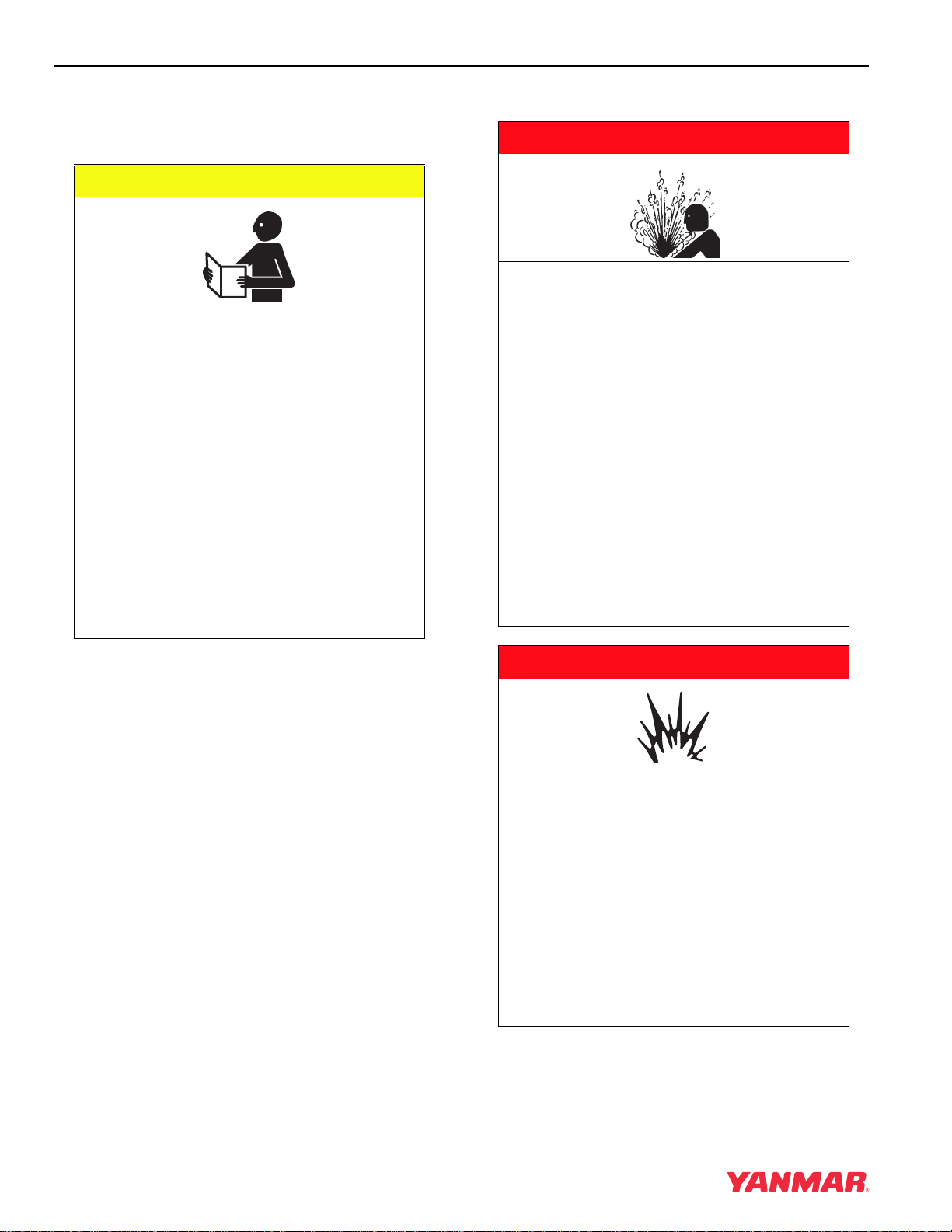
SAFETY
3-2 TNE Service Manual
SAFETY PRECAUTIONS
Before You Operate
During Operation and Maintenance
CAUTION
NEVER permit anyone to operate the
engine or driven machine without proper
training.
• Read and understand this Operation
Manual before you operate the
machine to ensure that you follow safe
operating practices and maintenance
procedures.
• Machine safety signs and labels are
additional reminders for safe operating
and maintenance techniques.
• See your authorized Yanmar industrial
engine dealer or distributor for
additional training.
0000002en
A DANGER
SCALD HAZARD!
• NEVER remove the radiator cap if the
engine is hot. Steam and hot engine
coolant will spurt out and seriously
burn you. Allow the engine to cool
down before you attempt to remove
the radiator cap.
• Securely tighten the radiator cap after
you check the radiator. Steam can
spurt out during engine operation if
the cap is loose.
• ALWAYS check the level of engine
coolant by observing the reserve tank.
• Failure to comply will result in death or
serious injury.
0000002en
A DANGER
EXPLOSION HAZARD!
• Keep the area around the battery well
ventilated. While the engine is running
or the battery is charging, hydrogen
gas is produced which can be easily
ignited.
• Keep sparks, open flame and any other
form of ignition away.
• Failure to comply will result in death or
serious injury.
0000003en
SAFETY
TNE Service Manual
3-3
A DANGER
FIRE AND EXPLOSION HAZARD!
• Diesel fuel is extremely flammable and
explosive under certain conditions.
• When you remove any fuel system
component to perform maintenance
(such as changing the fuel filter) place
an approved container under the
opening to catch the fuel.
• NEVER use a shop rag to catch the
fuel. Vapors from the rag are extremely
flammable and explosive.
• Wipe up any spills immediately.
• Wear eye protection. The fuel system
is under pressure and fuel could spray
out when you remove any fuel system
component.
• Failure to comply will result in death or
serious injury.
0000009en
A DANGER
FIRE AND EXPLOSION HAZARD!
• Diesel fuel is extremely flammable and
explosive under certain conditions.
• NEVER use diesel fuel as a cleaning
agent.
• Failure to comply will result in death or
serious injury.
0000012en
A DANGER
FIRE AND EXPLOSION HAZARD!
• Diesel fuel is extremely flammable and
explosive under certain conditions.
• NEVER remove the fuel cap with
engine running.
• Failure to comply will result in death or
serious injury.
0000011en
SAFETY
3-4 TNE Service Manual
0
A DANGER
FIRE AND EXPLOSION HAZARD!
• Diesel fuel is extremely flammable and
explosive under certain conditions.
• Place an approved container under the
air bleed port when you prime the fuel
system. Never use a shop rag to catch
the fuel. Wipe up any spills
immediately. ALWAYS close the air
bleed port after you complete priming
the system.
• Wear eye protection. The fuel system
is under pressure and fuel could spray
out when you open the air bleed port.
• If the unit has an electric fuel pump,
turn the key switch to the ON position
for 10 to 15 seconds, or until the fuel
coming out of the air bleed port is free
of bubbles, to allow the electric fuel
pump to prime the system.
• If the unit has a mechanical fuel pump,
operate the fuel priming pump several
times until the fuel coming out of the
air bleed port is free of bubbles.
• Failure to comply will result in death or
serious injury.
0000006en
A DANGER
FIRE AND EXPLOSION HAZARD!
• Only use the key switch to start the
engine.
• NEVER jump start the engine. Sparks
caused by jumping the battery to the
starter terminals may cause a fire or
explosion.
• Failure to comply will result in death or
serious injury.
0000004en
A DANGER
FIRE AND EXPLOSION HAZARD!
• Diesel fuel is extremely flammable and
explosive under certain conditions.
• Only fill fuel tank with diesel fuel.
Filling fuel tank with gasoline may
result in a fire.
• NEVER refuel with engine running.
• Wipe up all spills immediately.
• Keep sparks, open flames or any other
form of ignition (match, cigarette,
static electric source) away when
fueling / refueling.
• NEVER overfill the fuel tank.
• Fill fuel tank and store fuel in a
well-ventilated area only.
• Failure to comply will result in death or
serious injury.
0000005en
SAFETY
TNE Service Manual
3-5
0
A DANGER
FIRE AND EXPLOSION HAZARD!
• Diesel fuel is extremely flammable and
explosive under certain conditions.
• Before you operate the engine, check
for fuel leaks. Replace rubberized fuel
hoses every two years or every 2000
hours of engine operation, whichever
comes first, even if the engine has
been out of service. Rubberized fuel
lines tend to dry out and become
brittle after two years or 2000 hours of
engine operation, whichever comes
first.
• Failure to comply will result in death or
serious injury.
0000015en
A DANGER
EXPLOSION HAZARD!
• NEVER check the remaining battery
charge by shorting out the terminals.
This will result in a spark and may
cause an explosion or fire. Use a
hydrometer to check the remaining
battery charge.
• If the electrolyte is frozen, slowly warm
the battery before you recharge it.
• Failure to comply will result in death or
serious injury.
0000007en
A DANGER
CRUSH HAZARD!
• When you need to transport an engine
for repair have a helper assist you
attach it to a hoist and load it on a
truck.
• NEVER stand under hoisted engine. If
the hoist mechanism fails, the engine
will fall on you, causing serious injury
or death.
• Failure to comply will result in death or
serious injury.
0000008en
SAFETY
3-6 TNE Service Manual
A WARNING
SEVER HAZARD!
• Keep hands and other body parts
away from moving / rotating parts
such as the cooling fan, flywheel or
PTO shaft.
• Wear tight fitting clothing and keep
your hair short or tie it back while the
engine is running.
• Remove all jewelry before you operate
or service the machine.
• NEVER start the engine in gear.
Sudden movement of the engine
and / or machine could cause death or
serious personal injury.
• NEVER operate the engine without the
guards in place.
• Before you start the engine make sure
that all bystanders are clear of the
area.
• Keep children and pets away while the
engine is operating.
• Check before starting the engine that
any tools or shop rags used during
maintenance have been removed from
the area.
• Failure to comply could result in death
or serious injury.
0000002en
A WARNING
EXHAUST HAZARD!
• NEVER operate the engine in an
enclosed area such as a garage,
tunnel, underground room, manhole or
ship’s hold without proper ventilation.
• NEVER block windows, vents, or other
means of ventilation if the engine is
operating in an enclosed area. All
internal combustion engines create
carbon monoxide gas during
operation. Accumulation of this gas
within an enclosure could cause
illness or even death.
• Make sure that all connections are
tightened to specifications after repair
is made to the exhaust system.
• Failure to comply could result in death
or serious injury.
0000003en
A WARNING
ALCOHOL AND DRUG HAZARD!
• NEVER operate the engine while you
are
under the influence of
alcohol or
drugs.
• NEVER operate the engine when you
are feeling ill.
• Failure to comply could result in death
or serious injury.
0000004en
SAFETY
TNE Service Manual
3-7
A WARNING
EXPOSURE HAZARD!
• Wear personal protective equipment
such as gloves, work shoes, eye and
hearing protection as required by the
task at hand.
• NEVER wear jewelry, unbuttoned
cuffs, ties or loose fitting clothing
when you are working near
moving / rotating parts such as the
cooling fan, flywheel or PTO shaft.
• ALWAYS tie long hair back when you
are working near moving / rotating
parts such as a cooling fan, flywheel,
or PTO shaft.
• NEVER operate the engine while
wearing a headset to listen to music or
radio because it will be difficult to hear
warning signals.
• Failure to comply could result in death
or serious injury.
0000005en
A WARNING
BURN HAZARD!
• Batteries contain sulfuric acid. NEVER
allow battery fluid to come in contact
with clothing, skin or eyes. Severe
burns could result. ALWAYS wear
safety goggles and protective clothing
when servicing the battery. If contact
with the skin and / or eyes should
occur, flush with a large amount of
water and obtain prompt medical
treatment.
• Failure to comply could result in death
or serious injury.
0000007en
A WARNING
HIGH PRESSURE HAZARD!
• Avoid skin contact with high pressure
diesel fuel spray caused by a fuel
system leak such as a broken fuel
injection line. High pressure fuel can
penetrate your skin and result in
serious injury. If you are exposed to
high pressure fuel spray obtain
prompt medical treatment.
• NEVER check for a fuel leak with your
hands. ALWAYS use a piece of wood
or cardboard. Have your authorized
Yanmar industrial engine dealer or
distributor repair the damage.
• Failure to comply could result in death
or serious injury.
0000008en
SAFETY
3-8 TNE Service Manual
A WARNING
SHOCK HAZARD!
• Turn off the battery switch (if
equipped) or disconnect the negative
battery cable before servicing the
electrical system.
• Check the electrical harnesses for
cracks, abrasions, and damaged or
corroded connectors. ALWAYS keep
the connectors and terminals clean.
• Failure to comply could result in death
or serious injury.
0000009en
A WARNING
SEVER HAZARD!
• Stop the engine before you begin to
service it.
• NEVER leave the key in the key switch
when you are servicing the engine.
Someone may accidentally start the
engine and not realize you are
servicing it. This could result in a
serious injury.
• If you must service the engine while it
is operating, remove all jewelry, tie
back long hair, and keep your hands,
other body parts and clothing away
from moving / rotating parts.
• Failure to comply could result in death
or serious injury.
0000010en
A WARNING
BURN HAZARD!
• If you must drain the engine oil while it
is still hot, stay clear of the hot engine
oil to avoid being scalded. Make sure
you wear eye protection.
• Failure to comply could result in death
or serious injury.
0000011en
A WARNING
BURN HAZARD!
• Wait until the engine cools before you
drain the engine coolant. Hot engine
coolant may splash and burn you.
• Failure to comply could result in death
or serious injury.
0000016en
SAFETY
TNE Service Manual
3-9
A WARNING
BURN HAZARD!
• Keep your hands, and other body
parts, away from hot engine surfaces
such as the muffler, exhaust pipe,
turbocharger (if equipped) and engine
block during operation and shortly
after you shut the engine down. These
surfaces are extremely hot while the
engine is operating and could
seriously burn you.
• Failure to comply could result in death
or serious injury.
0000015en
A CAUTION
COOLANT HAZARD!
• Wear eye protection and rubber gloves
when you handle Long Life or
Extended Life engine coolant. If
contact with the eyes or skin should
occur, wash immediately with clean
water.
• Failure to comply may result in minor
or moderate injury.
0000005en
A CAUTION
FLYING OBJECT HAZARD!
• ALWAYS wear eye protection when
servicing engine and when using
compressed air or high-pressure
water. Dust, flying debris, compressed
air, pressurized water or steam may
injure your eyes.
• Failure to comply may result in minor
or moderate injury.
0000003en
CAUTION
• Only use diesel fuels recommended by
Yanmar for the best engine
performance, to prevent engine
damage and to comply with EPA / ARB
warranty requirements.
• Only use clean diesel fuel.
• NEVER remove primary strainer from
the fuel tank filler port (if equipped). If
removed, dirt and debris could get into
the fuel system causing it to clog.
0000004en
CAUTION
NEVER attempt to adjust the low or high
idle speed limit screw. This may impair
the safety and performance of the
machine and shorten its life. If
adjustment is ever required, contact
your authorized Yanmar industrial
engine dealer or distributor.
0000045en

SAFETY
3-10 TNE Service Manual
CAUTION
If any problem is noted during the visual
check, the necessary corrective action
should be taken before you operate the
engine.
0000021en
CAUTION
NEVER hold the key in the START
position for longer than 15 seconds or
the starter motor will overheat.
0000007en
CAUTION
The illustrations and descriptions of
optional equipment in this manual, such
as the operator’s console, are for a
typical engine installation. Refer to the
documentation supplied by the optional
equipment manufacturer for specific
operation and maintenance instructions.
0000018en
CAUTION
If any indicator illuminates during
engine operation stop the engine
immediately. Determine the cause and
repair the problem before you continue
to operate the engine.
0000029en
CAUTION
Observe the following environmental
operating conditions to maintain engine
performance and avoid premature
engine wear:
• Avoid operating in extremely dusty
conditions.
• Avoid operating in the presence of
chemical gases or fumes.
• Avoid operating in a corrosive
atmosphere such as salt water spray.
• NEVER install the engine in a
floodplain unless proper precautions
are taken to avoid being subject to a
flood.
• NEVER expose the engine to the rain.
0000003enTNE

SAFETY
TNE Service Manual
3-11
CAUTION
Observe the following environmental
operating conditions to maintain engine
performance and avoid premature
engine wear:
• NEVER run the engine if the ambient
temperature is above +104°F (+40°C)
or below +5°F (-15°C).
◆ If the ambient temperature exceeds
+104°F (+40°C) the engine may
overheat and cause the engine oil to
break down.
◆ If the ambient temperature falls
below +5°F (-15°C) rubber
components such as gaskets and
seals will harden causing premature
engine wear and damage.
◆ Contact your authorized Yanmar
industrial engine dealer or
distributor if the engine will be
operated in either temperature
extreme.
• Contact your authorized Yanmar
industrial engine dealer or distributor
if you need to operate the engine at
high altitudes. At high altitudes the
engine will lose power, run rough, and
produce exhaust gases that exceed
the design specifications.
0000065enTNE
CAUTION
• Only use the engine oil specified.
Other engine oils may affect warranty
coverage, cause internal engine
components to seize, or shorten
engine life.
• Prevent dirt and debris from
contaminating engine oil. Carefully
clean the oil cap / dipstick and the
surrounding area before you remove
the cap.
• NEVER mix different types of engine
oil. This may adversely affect the
lubricating properties of the engine oil.
• NEVER overfill. Overfilling may result
in white exhaust smoke, engine
overspeed or internal damage.
0000005en
CAUTION
• Only use the engine coolant specified.
Other engine coolants may affect
warranty coverage, cause an internal
build up of rust and scale and / or
shorten engine life.
• Prevent dirt and debris from
contaminating engine coolant.
Carefully clean the radiator cap and
the surrounding area before you
remove the cap.
• NEVER mix different types of engine
coolants. This may adversely affect the
properties of the engine coolant.
0000006en
CAUTION
• NEVER overfill the engine with engine
oil.
• ALWAYS keep the oil level between
upper and lower lines on the dipstick.
0000015en

SAFETY
3-12 TNE Service Manual
CAUTION
For maximum engine life, Yanmar
recommends that when shutting the
engine down, you allow the engine to
idle, without load, for 5 minutes. This
will allow the engine components that
operate at high temperatures, such as
the turbocharger (if equipped) and
exhaust system, to cool slightly before
the engine itself is shut down.
0000008en
CAUTION
NEVER use an engine starting aid such
as ether. Engine damage will result.
0000009en
CAUTION
Make sure the engine is installed on a
level surface. If a continuously running
engine is installed at an angle greater
than 20° (in any direction) or if an engine
runs for short periods of time (less than
3 minutes) at an angle greater than 25°
in any direction, engine oil may enter the
combustion chamber causing exessive
engine speed and generate white
smoke. This may cause serious engine
damage.
0000010enTNE
CAUTION
New Engine Break In:
• On the initial engine start-up, allow the
engine to idle for approximately 15
minutes while you check for proper
engine oil pressure, diesel fuel leaks,
engine oil leaks, coolant leaks, and for
proper operation of the indicators
and / or gauges.
• During the first hour of operation, vary
the engine speed and load on the
engine. Short periods of maximum
engine speed and load are desirable.
Avoid prolonged operation at
minimum or maximum engine speeds
and loads for the next 4 to 5 hours.
• During the break-in period, carefully
observe the engine oil pressure and
engine temperature.
• During the break-in period, check the
engine oil and coolant levels
frequently.
0000011en
CAUTION
NEVER engage the starter motor while
the engine is running. This may damage
the starter motor pinion and / or ring
gear.
0000012en
SAFETY
TNE Service Manual
3-13
CAUTION
• NEVER attempt to modify the engine’s
design or safety features such as
defeating the engine speed limit
control or the fuel injection quantity
control.
• Failure to comply may impair the
engine’s safety and performance
characteristics and shorten the
engine’s life. Any alterations to this
engine may affect the warranty
coverage of your engine. See Yanmar
Limited Warranty on page 2-3.
0000044enTNESM
CAUTION
Be environmentally responsible. Follow
these procedures for hazardous waste
disposal. Failure to follow these
procedures may seriously harm the
environment.
• Follow the guidelines of the EPA or
other governmental agency for the
proper disposal of hazardous
materials such as engine oil, diesel
fuel and engine coolant. Consult the
local authorities or reclamation facility.
• NEVER dispose of hazardous
materials irresponsibly by dumping
them into a sewer, on the ground or
into ground water or waterways.
0000013en
CAUTION
Protect the air cleaner, turbocharger (if
equipped) and electric components
from damage when you use steam or
use high-pressure water to clean the
engine.
0000014en
CAUTION
NEVER use high pressure water or
compressed air at greater than 28 psi or
a wire brush to clean the radiator fins.
Radiator fins damage easily.
0000016en
CAUTION
NEVER attempt to adjust the low or high
idle speed limit screw. This may impair
the safety and performance of the
machine and shorten its life. If the idle
speed limit screws require adjustment,
see your authorized Yanmar industrial
engine dealer or distributor.
0000017en
CAUTION
The tightening torque in the Standard
Torque Chart (page 5-17) should be
applied only to the bolts with a “7” head.
(JIS strength classification: 7T)
• Apply 60% torque to
bolts that are not listed.
• Apply 80% torque when
tightened to aluminum alloy.
0000023enTNESM

SAFETY
3-14 TNE Service Manual
CAUTION
If any indicator fails to illuminate when
the key switch is in the ON position, see
your authorized Yanmar industrial
engine dealer or distributor for service
before operating the engine.
0000028en
CAUTION
Establish a periodic maintenance plan
according to the engine application and
make sure you perform the required
periodic maintenance at intervals
indicated. Failure to follow these
guidelines will impair the engine’s safety
and performance characteristics,
shorten the engine’s life and may affect
the warranty coverage on your engine.
See Yanmar Limited Warranty on
page 2-3.
Consult your authorized Yanmar
industrial engine dealer or distributor for
assistance when checking items marked
with a
z.
0000024enTNESM
CAUTION
It is important to perform daily checks
See Daily on page 5-19.
Periodic maintenance prevents
unexpected downtime, reduces the
number of accidents due to poor
machine performance and helps extend
the life of the engine.
0000060enTNESM
CAUTION
If the fuel filter / water separator is
positioned higher than the fuel level in
the fuel tank, water may not drip out
when the fuel filter / water separator
drain cock is opened. If this happens,
turn the air vent screw on the top of the
fuel filter / water separator 2-3 turns
counterclockwise.
Be sure to tighten the air vent screw
after the water has drained out.
0000025en
CAUTION
• When the engine is operated in dusty
conditions, clean the air cleaner
element more frequently.
• NEVER operate the engine with the air
cleaner or element(s) removed. This
may cause foreign material to enter the
engine and damage it.
0000026en
CAUTION
The maximum air intake restriction shall
be 0.90 psi (6.23 kPa; 635 mm Aq) or
less. Clean or replace the air cleaner
element if the air intake restriction
exceeds the above mentioned value.
0000046en
CAUTION
NEVER turn off the battery switch (if
equipped) or short the battery cables
during operation. Damage to the electric
system will result.
0000061en

TNE Service Manual
4-1
Section 4
GENERAL SERVICE
INFORMATION
TNE Service Manual
Table of Contents
Page
Component Identification……………………………………………………….. 4-3
Location of Labels ………………………………………………………………… 4-3
EPA / ARB Emission Control Regulations — USA Only……………….. 4-4
Emission Control Labels………………………………………………………… 4-4
EPA / ARB Labels ..…………………………………………………………. 4-4
The 97/68/EC Directive Certified Engines………………………………… 4-4
Engine Family………………………………………………………………………. 4-5
Function of Major Engine Components ……………………………………. 4-6
Function of Cooling System Components ………………………………… 4-8
Diesel Fuel ……………………………………………………………………….…. 4-9
Diesel Fuel Specifications …………………………..……………………. 4-9
Filling The Fuel Tank……………………………………………………… 4-10
Priming the Fuel System ..………………………………………………. 4-12
Engine Oil………………………………………………………………………….. 4-14
Engine Oil Specifications………………………………………………… 4-14
Engine Oil Viscosity……………………………………………………….. 4-14
Checking Engine Oil………………………………………………………. 4-15
Adding Engine Oil………………………………………………………….. 4-15
Engine Oil Capacity (Typical) ………………………………………….. 4-15
Engine Coolant…………………………………………………………………… 4-16
Engine Coolant Specifications…………………………………………. 4-16
Filling Radiator With Engine Coolant………………………………… 4-17
Engine Coolant Capacity (Typical) …………………………………… 4-18
Specifications …………………………………………………………………….. 4-19
Description of Model Number………………………………………….. 4-19

GENERAL SERVICE INFORMATION
4-2 TNE Service Manual
Engine Speed Specifications…………………………………………… 4-19
Engine General Specifications ………………………………………… 4-19
Principal Engine Specifications …………………………………………….. 4-20
4TNE92-NMH……………………………………………………………….. 4-20
4TNE92-NMHA …………………………………………………………….. 4-21
4TNE98-NMH……………………………………………………………….. 4-22
Engine Service Information ………………………………………………….. 4-23
Engine Tuning ………………………………………………………………. 4-23
Tightening Torques for Standard Bolts and Nuts …………………….. 4-24
Standard Torque Chart………………………………………………………… 4-25
Abbreviations and Symbols………………………………………………….. 4-26
Abbreviations………………………………………………………………… 4-26
Symbols……………………………………………………………………….. 4-26
Unit Conversions………………………………………………………………… 4-27
Unit Prefixes …………………………………………………………………. 4-27
Units of Length ……………………………………………………………… 4-27
Units of Volume …………………………………………………………….. 4-27
Units of Mass………………………………………………………………… 4-27
Units of Force ……………………………………………………………….. 4-27
Units of Torque……………………………………………………………… 4-27
Units of Pressure…………………………………………………………… 4-27
Units of Power ………………………………………………………………. 4-27
Units of Temperature……………………………………………………… 4-27
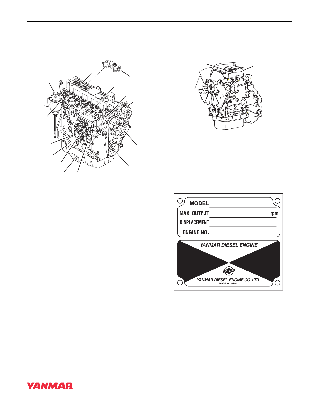
GENERAL SERVICE INFORMATION
TNE Service Manual
4-3
COMPONENT IDENTIFICATION
Figure 4-1 shows where major engine components
are located.
LOCATION OF LABELS
Figure 4-2 shows the location of regulatory and
safety labels on Yanmar TNE series engines.
Figure 4-2
The typical location of the emission control
information label is shown (Figure 4-2, (1)).
Typical location of the engine nameplate is shown
(Figure 4-2, (2)).
Engine Nameplate (Typical)
0001102A
(12)
(2)
(6)
(1)
(9)
(4)
(8)
(7)
(3)
(5)
(10)
(11)
(15)
(13)
(14)
Figure 4-1
1. Fuel Filter / Water
Separator
2. Top Filler Port
(Engine Oil)
3. Governor Lever
4. Fuel Injection
Pump
5. Side Filler Port
(Engine Oil)
6. Fuel Priming
Pump
7. Drain Plug
(Engine Oil)
8. Engine Oil Filter
9. Dipstick
(Engine Oil)
10. Engine Coolant
Pump
11. Alternator
12. Glow Plug
13. V-Belt
14. Crankshaft
V-Pulley
15. Starter Motor
(1)
0000585A
(2)
0000287
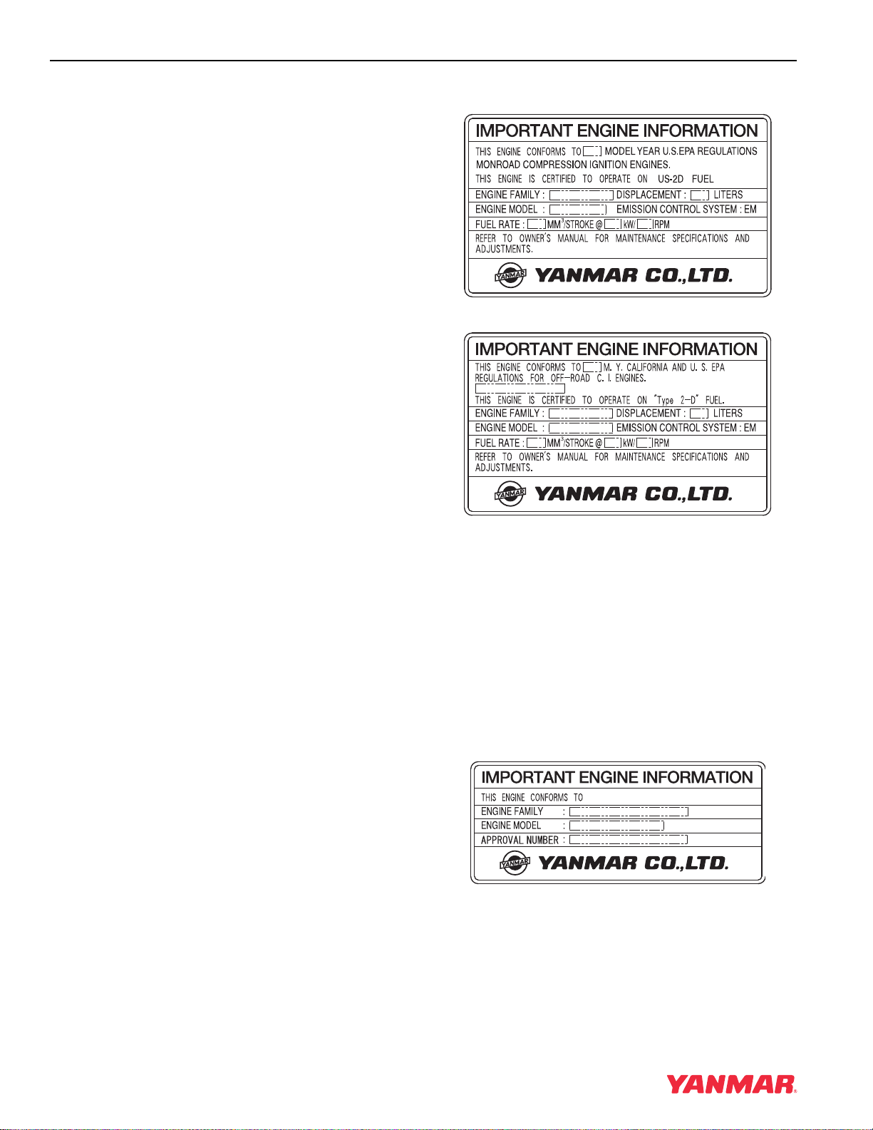
GENERAL SERVICE INFORMATION
4-4 TNE Service Manual
EPA / ARB EMISSION CONTROL
REGULATIONS — USA ONLY
Yanmar TNE engines meet Environmental
Protection Agency (EPA) (U. S. Federal) emission
control standards as well as the California Air
Resources Board (ARB, California) regulations.
Only engines that conform to ARB regulations can
be sold in the State of California.
Refer to the specific EPA / ARB installation (page
5-16) and maintenance (page 5-16) in the
Periodic Maintenance section of this manual. Also
refer to the Yanmar Co., Ltd. Limited Emission
Control System Warranty — USA Only on page 2-5.
EMISSION CONTROL LABELS
Since emission control regulations are being issued
on a global basis, it is necessary to identify which
regulations a particular engine complies with. We
have listed several different types of labels you
might find on your engine.
EPA / ARB Labels
THE 97/68/EC DIRECTIVE
CERTIFIED ENGINES
The engines described in this manual have been
certified by the 97/68/EC Directive.
To identify the engines that meet this certification,
the 97/68/EC emission control label is affixed on
the engines.
« «
(EPA & ARB)
(EPA) Less Than 50 HP SAE (37kW)
(97/68/EC)
97/68/EC DIRECTIVE

GENERAL SERVICE INFORMATION
TNE Service Manual
4-5
ENGINE FAMILY
The EPA / ARB labels and the 97/68/EC label all
have an Engine Family field. The following is an
explanation of the Engine Family designation:
3YDXL1.33M 3 N
Method of air aspiration
Number of cylinders
Engine speed specifications
Displacement (liter)
Non-road / Off-road engine
Yanmar Diesel
*2003 Model Year
3*: 2003
4 : 2004
5 : 2005
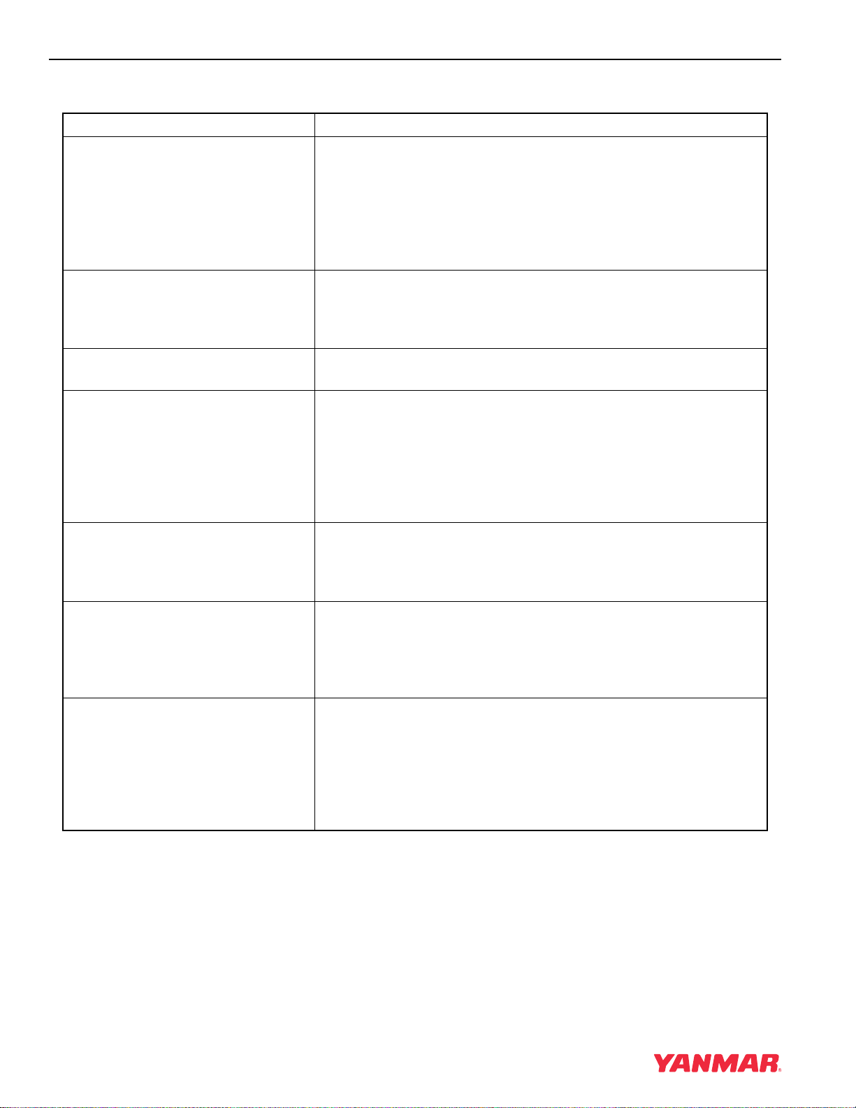
GENERAL SERVICE INFORMATION
4-6 TNE Service Manual
FUNCTION OF MAJOR ENGINE COMPONENTS
Components Functions
Air Cleaner The air cleaner prevents airborne contaminants from entering the
engine. Since the air cleaner is application specific, it must be
carefully selected by an application engineer. It is not part of the
basic engine package as shipped from the Yanmar factory.
Periodic replacement of the air cleaner filter element is necessary.
See the Periodic Maintenance Schedule on page 5-17 for the
replacement frequency.
Alternator The alternator is driven by a V-belt which is powered by the
crankshaft V-pulley. The alternator supplies electricity to the
engine systems and charges the battery while the engine is
running.
Dipstick (Engine Oil) The engine oil dipstick is used to determine the amount of engine
oil in the crankcase.
Electric Fuel Pump The electric fuel pump makes sure there is a constant supply of
diesel fuel to the fuel injection pump. The electric fuel pump is
electro-magnetic and runs on 12 VDC. An electric fuel pump may
be installed as an option or as standard equipment. Standard
equipment may vary based on engine model and specification. If
an electric fuel pump is installed, turn the key switch to the ON
position for 10 to 15 seconds to prime the fuel system.
Engine Oil Filter The engine oil filter removes contaminants and sediments from
the engine oil. Periodic replacement of the engine oil filter is
necessary. See the Periodic Maintenance Schedule on page 5-17
for the replacement frequency.
Fuel Filter The fuel filter removes contaminants and sediments from the
diesel fuel. Periodic replacement of the fuel filter is necessary. See
the Periodic Maintenance Schedule on page 5-17 for the
replacement frequency. Please note that the word “diesel” is
implied throughout this manual when the word “fuel” is used.
Fuel Filter / Water Separator The fuel filter / water separator removes contaminants, sediments
and water from diesel fuel going to the fuel filter. This is a required
component of the fuel system. This is standard equipment with
every engine. The separator is installed between the fuel tank and
the fuel pump. Periodically drain the water from the fuel filter /
water separator using the drain cock at the bottom of the
separator.

GENERAL SERVICE INFORMATION
TNE Service Manual
4-7
Fuel Priming Lever If the unit has a mechanical fuel pump, a fuel priming lever on the
mechanical fuel pump primes the fuel system. The fuel system
needs to be primed before you start the engine for the first time, if
you run out of fuel, or if fuel system service is performed. To prime
the fuel system, operate the fuel priming lever until the cup in the
fuel filter is full of fuel.
Fuel Tank The fuel tank is a reservoir that holds diesel fuel. When fuel leaves
the fuel tank it goes to the fuel filter / water separator. Next, fuel is
pumped to the fuel filter by the fuel pump. Next the fuel goes to the
fuel injection pump. Since fuel is used to keep the fuel injection
pump cool and lubricated, more fuel than necessary enters the
injection pump. When the injection pump pressure reaches a
preset value, a relief valve allows excess fuel to be returned back
to the fuel tank. The fuel tank is a required engine component.
Mechanical Fuel Pump The mechanical fuel pump is a diaphragm type of pump and is
installed on the fuel injection pump body. The mechanical fuel
pump is driven by a cam on the camshaft of the fuel injection
pump. An electric fuel pump is available as an option. The
mechanical fuel pump is not installed on the fuel injection pump if
the electric fuel pump option is installed.
Side and Top Filler Port (Engine Oil) You can fill the crankcase with engine oil from either the side or
top filler port depending upon which one is most convenient.
Starter Motor The starter motor is powered by the battery. When you turn the
key switch in the operator’s console to the START position, the
starter motor engages with the ring gear installed on the flywheel
and starts the flywheel in motion.
Components Functions

GENERAL SERVICE INFORMATION
4-8 TNE Service Manual
FUNCTION OF COOLING SYSTEM COMPONENTS
Components Functions
Cooling System
The TNE engine is liquid-cooled by means of a cooling system.
The cooling system consists of a radiator, radiator cap, engine
cooling fan, engine coolant pump, thermostat, and reserve tank.
Note that all cooling system components are required for
proper engine operation. Since some of the components are
application specific, they must be carefully selected by an
application engineer. The application specific items are not
part of the basic engine package as shipped from the Yanmar
factory.
• Engine Cooling Fan The engine cooling fan is driven by a V-belt which is powered by
the crankshaft V-pulley. The purpose of the engine cooling fan is
to circulate air through the radiator.
• Engine Coolant Pump The engine coolant pump circulates the engine coolant through
the cylinder block and cylinder head and returns the engine
coolant to the radiator.
• Radiator The radiator acts as a heat exchanger. As the engine coolant
circulates through the cylinder block it absorbs heat. The heat in
the engine coolant is dissipated in the radiator. As the engine
cooling fan circulates air through the radiator, the heat is
transferred to the air.
• Radiator Cap The radiator cap controls the cooling system pressure. The
cooling system is pressurized to raise the boiling point of the
engine coolant. As the engine coolant temperature rises, the
system pressure and the coolant volume increases. When the
pressure reaches a preset value, the release valve in the radiator
cap opens and the excess engine coolant flows into the reserve
tank. As the engine coolant temperature is reduced, the system
pressure and volume is reduced and the vacuum valve in the
radiator cap opens allowing engine coolant to flow from the
reserve tank back into the radiator.
• Reserve Tank The reserve tank contains the overflow of engine coolant from the
radiator. If you need to add engine coolant to the system, add it to
the reserve tank, not the radiator.
• Thermostat A thermostat is placed in the cooling system to prevent engine
coolant from circulating into the radiator until the engine coolant
temperature reaches a preset temperature. When the engine is
cold, no engine coolant flows through the radiator. Once the
engine reaches its operating temperature the thermostat opens.
By letting the engine warm up as quickly as possible, the
thermostat reduces engine wear, deposits and emissions.
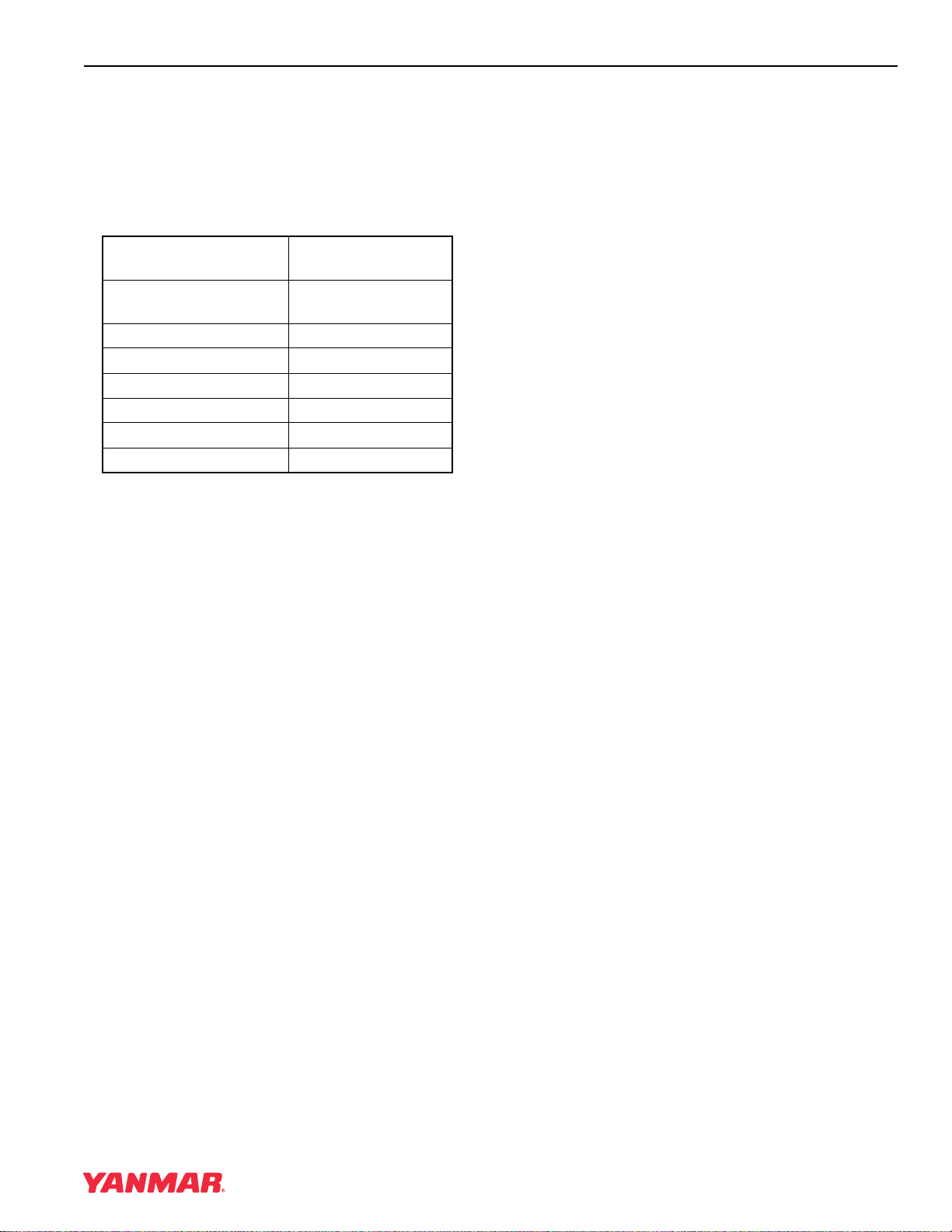
GENERAL SERVICE INFORMATION
TNE Service Manual
4-9
DIESEL FUEL
Diesel Fuel Specifications
Diesel fuel should comply with the following
specifications. The table lists several worldwide
specifications for diesel fuels.
Additional Technical Fuel Requirements
• The fuel cetane number should be equal to 45 or
higher.
• The sulfur content must not exceed 0.5% by
volume. Less than 0.05% is preferred.
• Bio-Diesel fuels. See Bio-Diesel Fuels on
page 4-9.
• NEVER mix kerosene, used engine oil, or
residual fuels with the diesel fuel.
• Water and sediment in the fuel should not exceed
0.05% by volume.
• Keep the fuel tank and fuel-handling equipment
clean at all times.
• Poor quality fuel can reduce engine performance
and / or cause engine damage.
• Fuel additives are not recommended. Some fuel
additives may cause poor engine performance.
Consult your Yanmar representative for more
information.
• Ash content not to exceed 0.01% by volume.
• Carbon residue content not to exceed 0.35% by
volume. Less than 0.1% is preferred.
• Total aromatics content should not exceed 35%
by volume. Less than 30% is preferred.
• PAH (polycyclic aromatic hydrocarbons) content
should be below 10% by volume.
• Metal content of Na, Mg, Si, and Al should be
equal to or lower than 1 mass ppm. (Test analysis
method JPI-5S-44-95)
• Lubricity: Wear mark of WS1.4 should be Max.
0.018 in (460
µm) at HFRR test.
Bio-Diesel Fuels
In Europe and in the United States, as well as some
other countries, non-mineral oil based fuel
resources such as RME (Rapeseed Methyl Ester)
and SOME (Soybean Methyl Ester), collectively
known as FAME (Fatty Acid Methyl Esters), are
being used as extenders for mineral oil derived
diesel fuels.
Yanmar approves the use of bio-diesel fuels that do
not exceed a blend of 5% (by volume) of FAME with
95% (by volume) of approved mineral oil derived
diesel fuel. Such bio-diesel fuels are known in the
marketplace as B5 diesel fuels.
These B5 diesel fuels must meet certain
requirements.
1. The bio-fuels must meet the minimum
specifications for the country in which they are
used.
• In Europe, bio-diesel fuels must comply with
the European Standard EN14214.
• In the United States, bio-diesel fuels must
comply with the American Standard ASTM
D-6751.
2. Bio-fuels should be purchased only from
recognized and authorized diesel fuel suppliers.
Precautions and concerns regarding the use of
bio-fuels:
1. Free methanol in FAME may result in corrosion
of aluminum and zinc FIE components.
Diesel Fuel
Specification
Location
No. 2-D, No. 1-D, ASTM
D975-94
USA
EN590:96 European Union
ISO 8217 DMX International
BS 2869-A1 or A2 United Kingdom
JIS K2204 Grade No.2 Japan
KSM-2610 Korea
GB252 China
GENERAL SERVICE INFORMATION
4-10 TNE Service Manual
2. Free water in FAME may result in plugging of
fuel filters and increased bacterial growth.
3. High viscosity at low temperatures may result in
fuel delivery problems, injection pump seizures,
and poor injection nozzle spray atomization.
4. FAME may have adverse effects on some
elastomers (seal materials) and may result in
fuel leakage and dilution of the engine
lubricating oil.
5. Even bio-diesel fuels that comply with a suitable
standard as delivered, will require additional
care and attention to maintain the quality of the
fuel in the equipment or other fuel tanks. It is
important to maintain a supply of clean, fresh
fuel. Regular flushing of the fuel system, and /
or fuel storage containers, may be necessary.
6. The use of bio-diesel fuels that do not comply
with the standards as agreed to by the diesel
engine manufacturers and the diesel fuel
injection equipment manufacturers, or
bio-diesel fuels that have degraded as per the
precautions and concerns above, may affect
the warranty coverage of your engine. See
Yanmar Co., Ltd. Limited Emission
Control System Warranty — USA Only on
page 2-5.
Filling The Fuel Tank
A DANGER
FIRE AND EXPLOSION HAZARD!
• Diesel fuel is extremely flammable and
explosive under certain conditions.
• Only fill fuel tank with diesel fuel.
Filling fuel tank with gasoline may
result in a fire.
• NEVER refuel with engine running.
• Wipe up all spills immediately.
• Keep sparks, open flames or any other
form of ignition (match, cigarette,
static electric source) away when
fueling / refueling.
• NEVER overfill the fuel tank.
• Fill fuel tank and store fuel in a
well-ventilated area only.
• Failure to comply will result in death or
serious injury.
0000005en
GENERAL SERVICE INFORMATION
TNE Service Manual
4-11
Note that a typical fuel tank is shown. The fuel tank
on your equipment may be different.
1. Clean the area around the fuel cap
(Figure 4-2, (1)).
2. Remove the fuel cap (Figure 4-2, (1)) from the
fuel tank (Figure 4-2, (2)).
A DANGER
FIRE AND EXPLOSION HAZARD!
• Diesel fuel is extremely flammable and
explosive under certain conditions.
• Be sure to place the diesel fuel
container on the ground when
transferring diesel fuel from the pump
to the container. Hold the hose nozzle
firmly against the side of the container
while filling it. This prevents static
electricity build-up which could cause
sparks and ignite fuel vapors.
• NEVER place diesel fuel or other
flammable material such as oil, hay or
dried grass close to the engine during
engine operation or shortly after shut
down.
• Failure to comply will result in death or
serious injury.
0000014en
A DANGER
FIRE AND EXPLOSION HAZARD!
• Diesel fuel is extremely flammable and
explosive under certain conditions.
• Before you operate the engine, check
for fuel leaks. Replace rubberized fuel
hoses every two years or every 2000
hours of engine operation, whichever
comes first, even if the engine has
been out of service. Rubberized fuel
lines tend to dry out and become
brittle after two years or 2000 hours of
engine operation, whichever comes
first.
• Failure to comply will result in death or
serious injury.
0000015en
CAUTION
• Only use diesel fuels recommended by
Yanmar for the best engine
performance, to prevent engine
damage and to comply with EPA / ARB
warranty requirements.
• Only use clean diesel fuel.
• NEVER remove primary strainer from
the fuel tank filler port (if equipped). If
removed, dirt and debris could get into
the fuel system causing it to clog.
0000004en
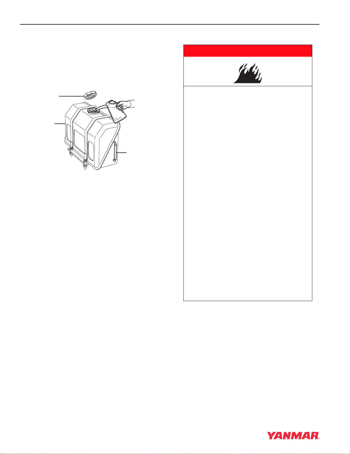
GENERAL SERVICE INFORMATION
4-12 TNE Service Manual
3. Observe the fuel level sight gauge
(Figure 4-2, (3)) and stop fueling when gauge
shows fuel tank is full. NEVER overfill the fuel
tank.
4. Replace the fuel cap (Figure 4-2, (1)) and hand
tighten. Over-tightening the fuel cap will
damage it.
Figure 4-3
Priming the Fuel System
0000002A
(1)
(2)
(3)
A DANGER
FIRE AND EXPLOSION HAZARD!
• Diesel fuel is extremely flammable and
explosive under certain conditions.
• Place an approved container under the
air bleed port when you prime the fuel
system. Never use a shop rag to catch
the fuel. Wipe up any spills
immediately. ALWAYS close the air
bleed port after you complete priming
the system.
• Wear eye protection. The fuel system
is under pressure and fuel could spray
out when you open the air bleed port.
• If the unit has an electric fuel pump,
turn the key switch to the ON position
for 10 to 15 seconds, or until the fuel
coming out of the air bleed port is free
of bubbles, to allow the electric fuel
pump to prime the system.
• If the unit has a mechanical fuel pump,
operate the fuel priming pump several
times until the fuel coming out of the
air bleed port is free of bubbles.
• Failure to comply will result in death or
serious injury.
0000006en
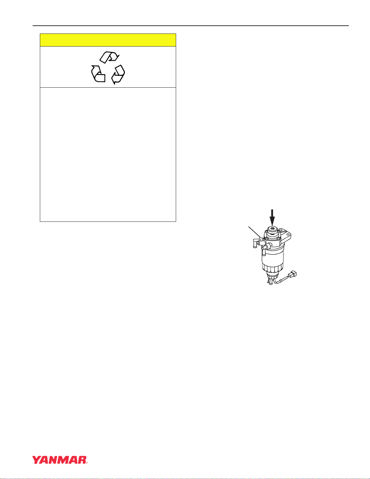
GENERAL SERVICE INFORMATION
TNE Service Manual
4-13
The fuel system needs to be primed under certain
conditions.
• Before starting the engine for the first time.
• After running out of fuel and fuel has been added
to the fuel tank.
• After fuel system maintenance such as changing
the fuel filter and draining the fuel filter / water
separator, or replacing a fuel system component.
To prime the fuel system on engines equipped with
an electric fuel pump:
1. Place an approved container under the air
bleed port.
2. Loosen the air bleed port 2 or 3 turns.
3. Turn the key to the ON position for 10 to 15
seconds or until the fuel coming out of the air
bleed port is free of bubbles.
4. Tighten the air bleed port.
5. Wipe up any spills and properly dispose of fuel.
6. NEVER use the starter motor to crank the
engine in order to prime the fuel system. This
may cause the starter motor to overheat and
damage the coils, pinion and / or ring gear.
To prime the fuel system on engines not equipped
with an electric fuel system:
1. Place an approved container under the air
bleed port.
2. Loosen the air bleed port (Figure 4-4, (1)) 2 or
3 turns.
3. Operate the fuel priming pump (Figure 4-4, (2))
until the fuel coming out of the air bleed port is
free of bubbles.
4. Tighten the air bleed port.
5. Wipe up any spills and properly dispose of fuel.
6. NEVER use the starter motor to crank the
engine in order to prime the fuel system. This
may cause the starter motor to overheat and
damage the coils, pinion and / or ring gear.
Figure 4-4
CAUTION
Be environmentally responsible. Follow
these procedures for hazardous waste
disposal. Failure to follow these
procedures may seriously harm the
environment.
• Follow the guidelines of the EPA or
other governmental agency for the
proper disposal of hazardous
materials such as engine oil, diesel
fuel and engine coolant. Consult the
local authorities or reclamation facility.
• NEVER dispose of hazardous
materials irresponsibly by dumping
them into a sewer, on the ground or
into ground water or waterways.
0000013en
0000862B
(2)
(1)
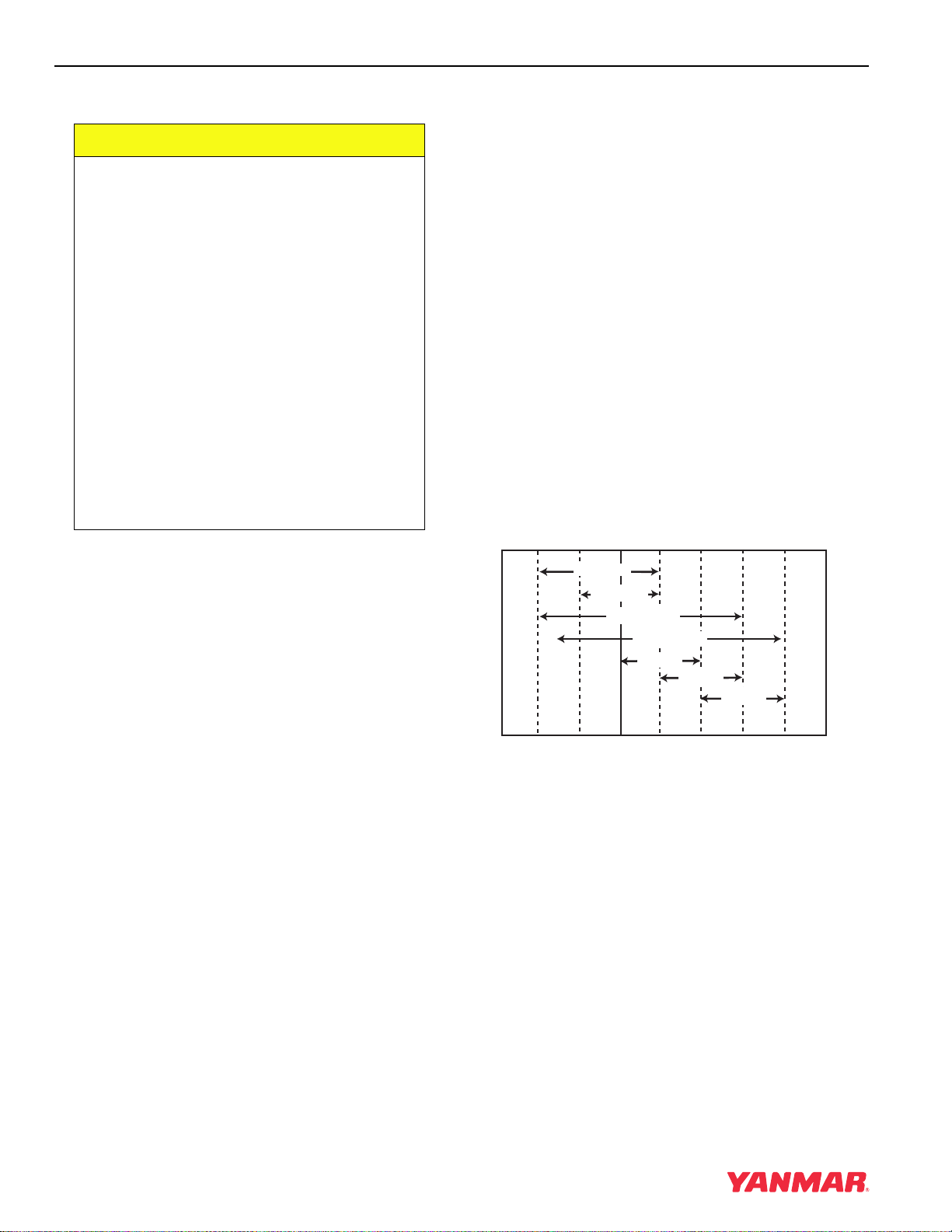
GENERAL SERVICE INFORMATION
4-14 TNE Service Manual
ENGINE OIL
Engine Oil Specifications
Use an engine oil that meets or exceeds the
following guidelines and classifications:
Service Categories
• API Service Categories CD or higher
• ACEA Service Categories E-3, E-4, and E-5
• JASO Service Category DH-1
Definitions
• API Classification (American Petroleum Institute)
• ACEA Classification (Association des
Constructeurs Européens d’Automobilies)
• JASO (Japanese Automobile Standards
Organization)
Note:
1. Be sure the engine oil, engine oil storage
containers, and engine oil filling equipment
are free of sediments and water.
2. Change the engine oil after the first 50 hours
of operation and then at every 250 hours
thereafter.
3. Select the oil viscosity based on the ambient
temperature where the engine is being
operated. See the SAE Service Grade
Viscosity Chart (Figure 4-5).
4. Yanmar does not recommend the use of
engine oil “additives.”
Additional Technical Engine oil
Requirements:
The engine oil must be changed when the Total
Base Number (TBN) has been reduced to 2.0. TBN
(mgKOH/g) test method; JIS K-201-5.2-2 (HCI),
ASTM D4739 (HCI).
Engine Oil Viscosity
Select the appropriate engine oil viscosity based on
the ambient temperature and use the SAE Service
Grade Viscosity Chart in Figure 4-5.
Figure 4-5
CAUTION
• Only use the engine oil specified.
Other engine oils may affect warranty
coverage, cause internal engine
components to seize, or shorten
engine life.
• Prevent dirt and debris from
contaminating engine oil. Carefully
clean the oil cap / dipstick and the
surrounding area before you remove
the cap.
• NEVER mix different types of engine
oil. This may adversely affect the
lubricating properties of the engine oil.
• NEVER overfill. Overfilling may result
in white exhaust smoke, engine
overspeed or internal damage.
0000005en
-4˚F 14˚F 32˚F 50˚F 68˚F 86˚F 104˚F
(-20˚C) (-10˚C) (0˚C) (10˚C) (20˚C) (30˚C) (40˚C)
SAE 10W
SAE 20W
SAE 10W-30
SAE 15W-40
SAE 20
SAE 30
SAE 40
0000005
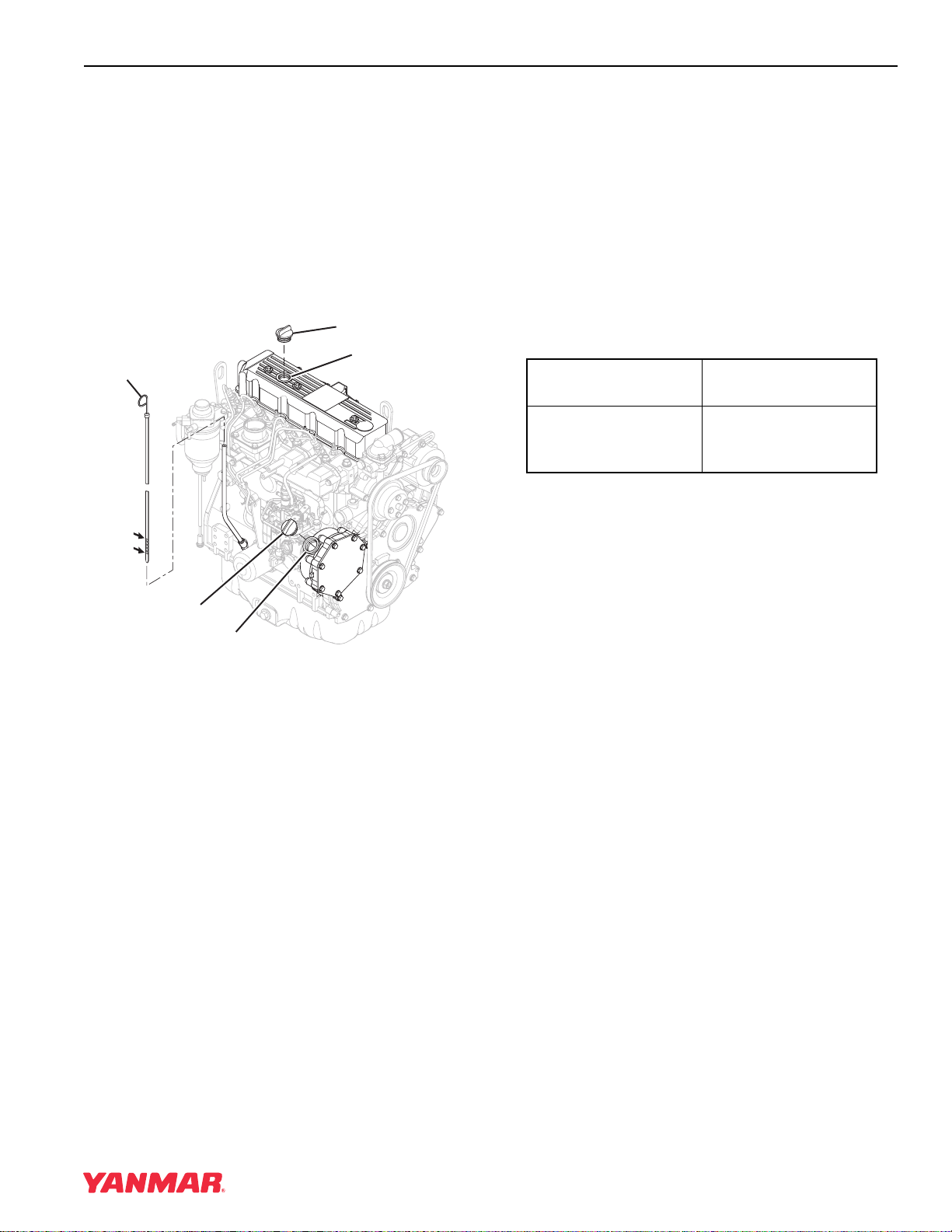
GENERAL SERVICE INFORMATION
TNE Service Manual
4-15
Checking Engine Oil
1. Make sure engine is level.
2. Remove dipstick (Figure 4-6, (1)) and wipe with
clean cloth.
3. Fully reinsert dipstick.
4. Remove dipstick. The oil level should be
between upper (Figure 4-6, (2)) and lower
(Figure 4-6, (3)) lines on the dipstick.
5. Fully reinsert dipstick.
Figure 4-6
Adding Engine Oil
1. Make sure engine is level.
2. Remove oil cap (Figure 4-6, (4)).
3. Add indicated amount of engine oil at the top or
side engine oil filler port (Figure 4-6, (5)).
4. Wait three minutes and check oil level.
5. Add more oil if necessary.
6. Replace oil cap (Figure 4-6, (4)) and hand
tighten. Over-tightening may damage the cap.
Engine Oil Capacity (Typical)
Note: These are the engine oil capacities
associated with a “Deep Standard” oil
pan. Oil capacity will vary dependant
upon which optional oil pan is used.
Refer to the operation manual provided
by the driven machine manufacturer for
the actual engine oil capacity of your
machine.
The following are typical engine oil capacities for
4TNE92-NMH, 4TNE92-NMHA, and 4TNE98-NMH
engines.
(2)
(1)
(4)
(5)
(3)
(4)
(5)
0001108A
Engine Model
Dipstick Upper
Limit / Lower Limit
4TNE92-NMH
4TNE92-NMHA
4TNE98-NMH
9.7 / 7.6 qt
(9.2 / 7.2 L)
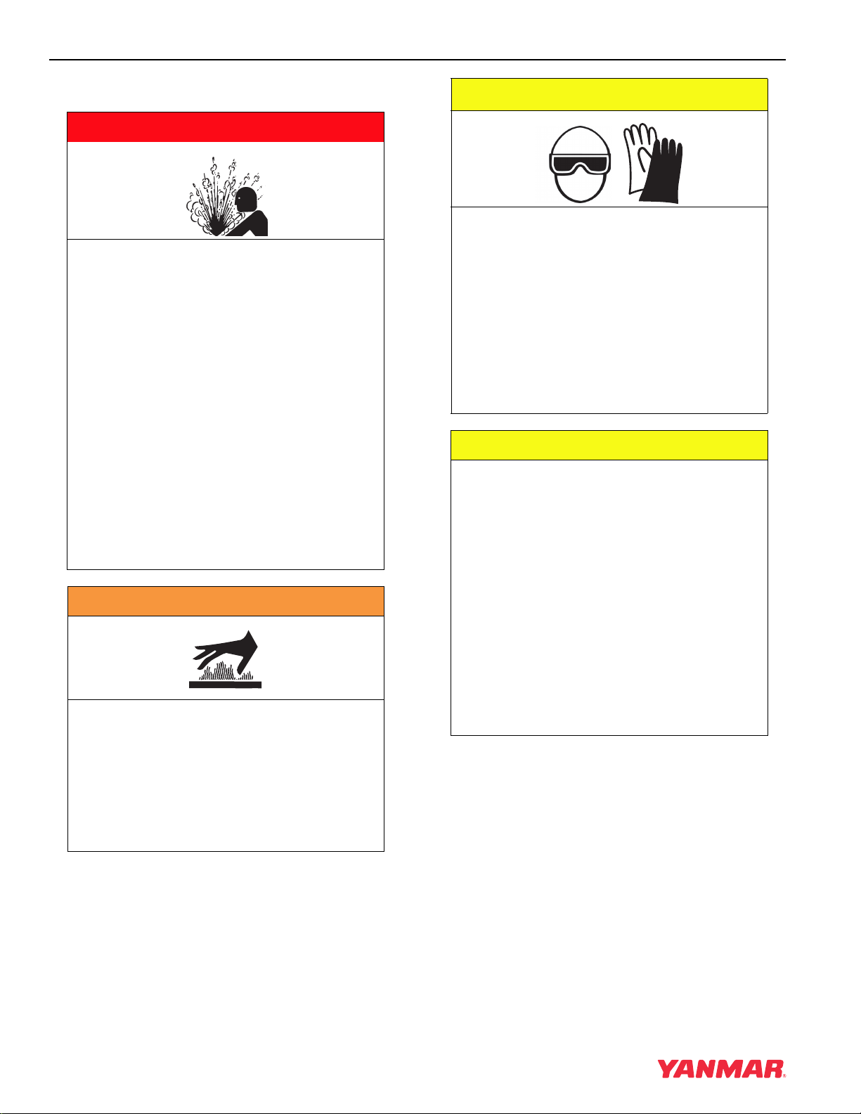
GENERAL SERVICE INFORMATION
4-16 TNE Service Manual
ENGINE COOLANT
Engine Coolant Specifications
Use a Long Life Coolant (LLC) or an Extended Life
Coolant (ELC) that meets or exceeds the following
guidelines and specifications.
Alternative Engine Coolant
If an Extended or Long Life Coolant is not available,
alternatively, you may use an ethylene glycol or
propylene glycol based conventional coolant
(green).
A DANGER
SCALD HAZARD!
• NEVER remove the radiator cap if the
engine is hot. Steam and hot engine
coolant will spurt out and seriously
burn you. Allow the engine to cool
down before you attempt to remove
the radiator cap.
• Securely tighten the radiator cap after
you check the radiator. Steam can
spurt out during engine operation if
the cap is loose.
• ALWAYS check the level of engine
coolant by observing the reserve tank.
• Failure to comply will result in death or
serious injury.
0000002en
A WARNING
BURN HAZARD!
• Wait until the engine cools before you
drain the engine coolant. Hot engine
coolant may splash and burn you.
• Failure to comply could result in death
or serious injury.
0000016en
A CAUTION
COOLANT HAZARD!
• Wear eye protection and rubber gloves
when you handle Long Life or
Extended Life engine coolant. If
contact with the eyes or skin should
occur, wash immediately with clean
water.
• Failure to comply may result in minor
or moderate injury.
0000005en
CAUTION
• Only use the engine coolant specified.
Other engine coolants may affect
warranty coverage, cause an internal
build up of rust and scale and / or
shorten engine life.
• Prevent dirt and debris from
contaminating engine coolant.
Carefully clean the radiator cap and
the surrounding area before you
remove the cap.
• NEVER mix different types of engine
coolants. This may adversely affect the
properties of the engine coolant.
0000006en
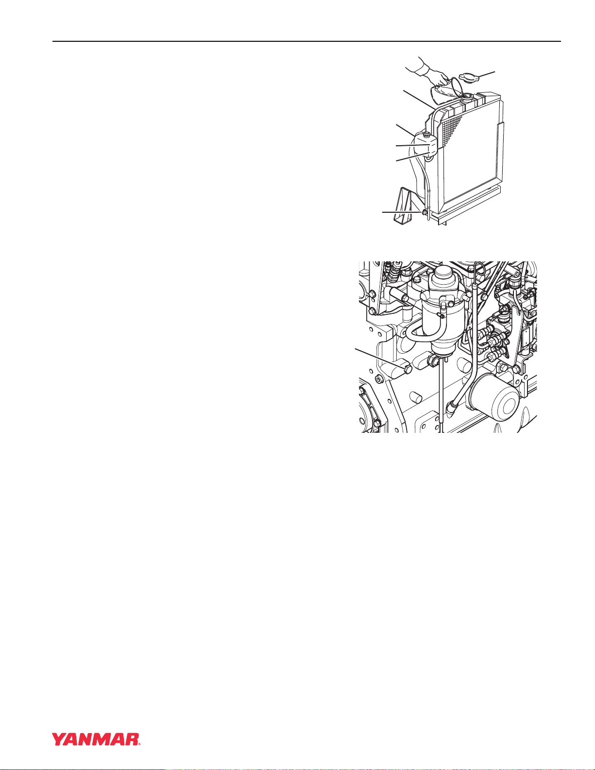
GENERAL SERVICE INFORMATION
TNE Service Manual
4-17
Notes:
1. ALWAYS use a mix of coolant and water.
NEVER use water only.
2. Mix coolant and water per the mixing
instructions on the coolant container.
3. Water quality is important to coolant
performance. Yanmar recommends that soft,
distilled, or demineralized water be used to
mix with coolants.
4. NEVER mix extended or long life coolants
and conventional (green) coolants.
5. NEVER mix different types and / or colors of
extended life coolants.
6. Replace the coolant every 1000 engine hours
or once a year.
Additional Technical Coolant
Specifications:
• ASTM D6210, D4985 (US)
• JIS K-2234 (Japan)
• SAE J814C, J1941, J1034 or J2036
(International)
Filling Radiator With Engine Coolant
Fill the radiator and reserve tank as follows. This
procedure is for filling the radiator for the first time
or refilling it after it is flushed. Note that a typical
radiator is illustrated.
1. Check to be sure the radiator drain plug is
installed and tightened or the drain cock
(Figure 4-7, (1)) is closed. Also make sure the
cylinder block drain plug (Figure 4-8, (1)) is
installed and tightened.
Figure 4-7
Figure 4-8
2. Remove the radiator cap (Figure 4-7, (2)) by
turning it counter-clockwise about 1/3 of a turn.
FULL
LOW
0000029A
(5)
(3)
(6)
(4)
(2)
(1)
(1)
0001578A

GENERAL SERVICE INFORMATION
4-18 TNE Service Manual
3. Pour the engine coolant slowly into the radiator
until it is even with the lip of the engine coolant
filler port. Make sure that air bubbles do not
develop as you fill the radiator.
4. Reinstall the radiator cap (Figure 4-7, (2)).
Align the tabs on the back side of the radiator
cap with the notches on the engine coolant filler
port. Press down and turn the cap clockwise
about 1/3 of a turn.
5. Remove the cap of the reserve tank
(Figure 4-7, (3)), and fill it to the LOW (COLD)
mark (Figure 4-7, (4)) with engine coolant.
Reinstall the cap.
6. Check the hose (Figure 4-7, (5)) that connects
the reserve tank (Figure 4-7, (3)) to the
radiator. Be sure it is securely connected and
there are no cracks or damage. If the hose is
damaged, engine coolant will leak out instead
of going into the reserve tank.
7. Run the engine until it is at operating
temperature. Check the level of engine coolant
in the reserve tank. When the engine is running
and the engine coolant is at normal
temperature, the coolant level in the tank should
be at the FULL (HOT) mark (Figure 4-7, (6)). If
the engine coolant is not at the FULL (HOT)
mark, add additional engine coolant to the
reserve tank to bring the level to the FULL
(HOT) mark.
Engine Coolant Capacity (Typical)
Note: Capacities listed are for the engine only
without a radiator. Refer to the operation
manual provided by the driven machine
manufacturer for the total cooling system
capacity of your specific machine.
The following are typical engine coolant capacities
for 4TNE92-NMH, 4TNE92-NMHA, and
4TNE98-NMH engines.
Engine Model
Engine Coolant
Capacity
4TNE92-NMH
4TNE92-NMHA
4TNE98-NMH
1.11 gal. (4.2 L)
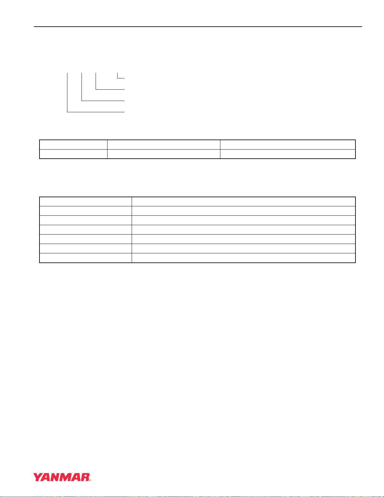
GENERAL SERVICE INFORMATION
TNE Service Manual
4-19
SPECIFICATIONS
Description of Model Number
Engine Speed Specifications
VM: Variable Medium Speed
Engine General Specifications
Notes:
1. The information described in Principal Engine Specifications is for a “standard” engine. To obtain the
information for the engine installed in your driven machine, please refer to the manual provided by the
driven machine manufacturer.
2. Engine rating conditions are as follows (SAE J1349, ISO 3046/1):
• Atmospheric Condition: Room temperature 77°F (25°C), Atmospheric pressure 29.53 in Hg (100 kPa,
750 mm Hg), Relative humidity 30%
• Fuel Temperature at Fuel Injector Pump Inlet: 104°F (40°C)
• With Cooling Fan, Air Cleaner, Muffler: Yanmar Standard
• After Engine Break-In Period. Output Allowable Deviation: ± 3%
• 1 PS = 0.7355 kW
• 1 hp SAE (Society of Automotive Engineers)= 0.7457 kW
4TNE92-OO
Customer / Machine Code
Cylinder Bore (in terms of mm)
Yanmar Diesel Engine Series
Number of Cylinders (4)
NOTATION AVAILABLE ENGINE SPEED INTENDED USES
VM 2000 ~ 2500 rpm (min
-1
) Agricultural, Constructive, Industrial Machines
Type Vertical Inline, Water Cooled, 4-Cycle Diesel Engine
Combustion System Indirect Injection
Starting System Electric Starting
Cooling System Radiator
Lubricating System Forced Lubrication With Trochoid Pump
PTO Position Flywheel End
Direction of Rotation Counterclockwise Viewed from Flywheel Side
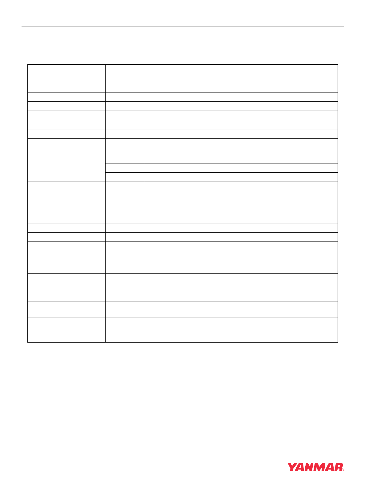
GENERAL SERVICE INFORMATION
4-20 TNE Service Manual
PRINCIPAL ENGINE SPECIFICATIONS
4TNE92-NMH
* Engine specifications do not include height of
lifting eyes nor dimensions or specifications for the
Cooling Fan, Radiator, Muffler, and Air Cleaner.
Engine Model 4TNE92-NMH
Version VM
Type Vertical Inline Diesel Engine
Combustion System Indirect Injection
Aspiration Natural
No. of Cylinders 4
Bore × Stroke 3.62 x 3.94 in (92
× 100 mm)
Displacement 162.3 cu in (2.659 L)
Max. Rated Output (Net) rpm
(min
-1
)
2450
hp SAE 45.1
kW 33.6
PS 45.7
High Idle Speed
(Bare Engine)
2725 ± 25 rpm
Low Idle Speed
(Bare Engine)
850 ± 25 rpm
Engine Weight (Dry)* 491.6 lb (194 kg)
PTO Position Flywheel Side
Direction of Rotation Counterclockwise Viewed From Flywheel Side
Cooling System Liquid-Cooled With Radiator
Lubricating System Forced Lubrication With Trochoid Pump
At normal operating speeds, oil pressure is: 42 — 57 psi (0.29 — 0.39 MPa; 3.0 — 4.0 kgf/cm
2
)
At idle, oil pressure is: No less than 8.5 psi (0.06 MPa; 0.6 kgf/cm
2
)
Starting System Electric Starting — Starter Motor: DC12V, 3.1 hp (2.3 kW)
Alternator: DC12V, 60A
Recommended Battery Capacity: 12V, 622 CCA (Cold Cranking Amps)
Dimensions (L × W × H)* 24.9 x 19.6 x 28.0 in
(632 x 498 x 711 mm)
Engine Oil Pan Capacity 9.7 / 7.6 qt (9.2 / 7.2 L)
(Dipstick Upper Limit / Lower Limit)
Engine Coolant Capacity 1.11 gal (4.2 L) Engine Only
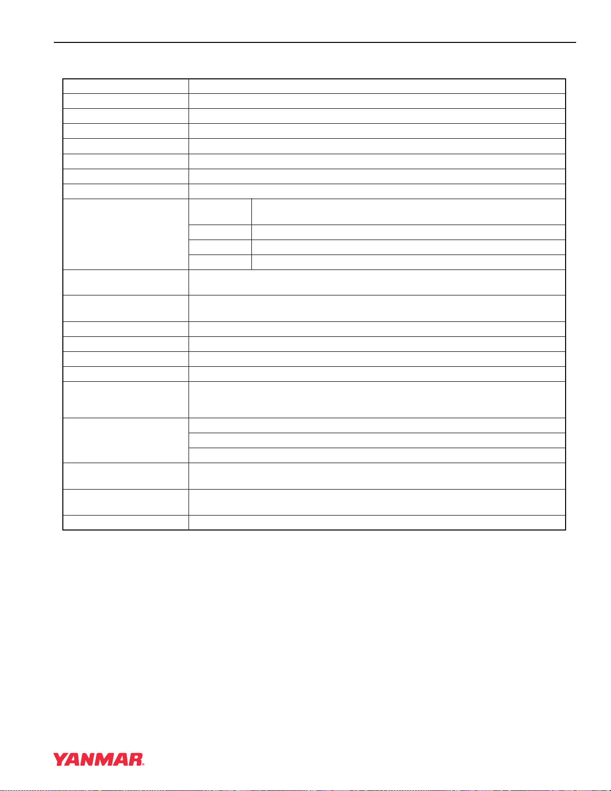
GENERAL SERVICE INFORMATION
TNE Service Manual
4-21
4TNE92-NMHA
* Engine Specifications Without Cooling Fan,
Radiator, Muffler, and Air Cleaner.
Engine Model 4TNE92-NMHA
Version VM
Type Vertical Inline Diesel Engine
Combustion System Indirect Injection
Aspiration Natural
No. of Cylinders 4
Bore × Stroke 3.62 x 3.94 in (92
× 100 mm)
Displacement 162.3 cu in (2.659 L)
Max. Rated Output (Net) rpm
(min
-1
)
2050
hp SAE 39.0
kW 29.1
PS 39.6
High Idle Speed
(Bare Engine)
2450 ± 25 rpm
Low Idle Speed
(Bare Engine)
850 ± 25 rpm
Engine Weight (Dry)* 491.6 lb (194 kg)
PTO Position Flywheel Side
Direction of Rotation Counterclockwise Viewed From Flywheel Side
Cooling System Liquid-Cooled With Radiator
Lubricating System Forced Lubrication With Trochoid Pump
At normal operating speeds, oil pressure is: 42 — 57 psi (0.29 — 0.39 MPa; 3.0 — 4.0 kgf/cm
2
)
At idle, oil pressure is: No less than 8.5 psi (0.06 MPa; 0.6 kgf/cm
2
)
Starting System Electric Starting — Starter Motor: DC12V, 3.1 hp (2.3 kW)
Alternator: DC12V, 60A
Recommended Battery Capacity: 12V, 622 CCA (Cold Cranking Amps)
Dimensions (L × W × H)* 24.9 x 19.6 x 26.6 in
(632 x 498 x 676 mm)
Engine Oil Pan Capacity 9.7 / 7.6 qt (9.2 / 7.2 L)
(Dipstick Upper Limit / Lower Limit)
Engine Coolant Capacity 1.11 gal (4.2 L) Engine Only
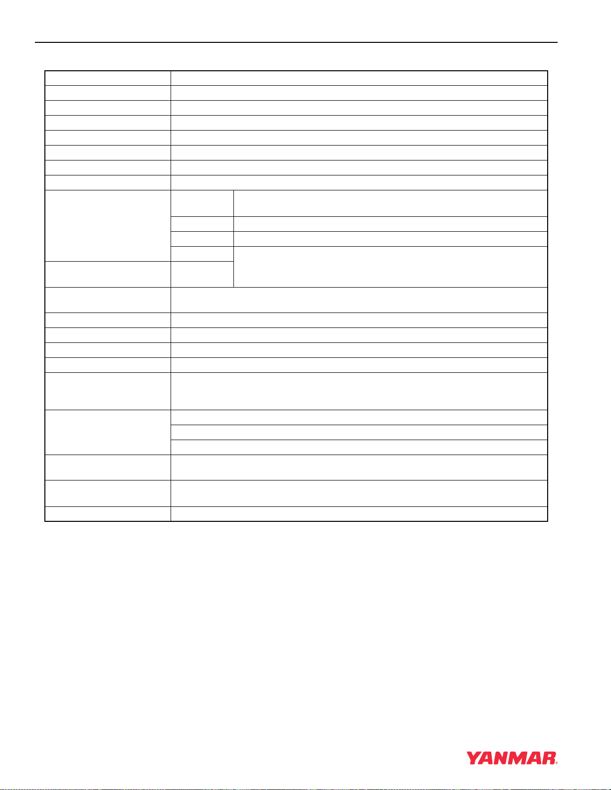
GENERAL SERVICE INFORMATION
4-22 TNE Service Manual
4TNE98-NMH
* Engine Specifications Without Cooling Fan,
Radiator, Muffler, and Air Cleaner.
Engine Model 4TNE98-NMH
Version VM
Type Vertical Inline Diesel Engine
Combustion System Indirect Injection
Aspiration Natural
No. of Cylinders 4
Bore × Stroke 3.86 x 4.33 in (98
× 110 mm)
Displacement 202.5 cu in (3.319 L)
Max. Rated Output (Net) rpm
(min
-1
)
2400
hp SAE 63.6
kW 47.4
PS
64.4
High Idle Speed
(Bare Engine)
2725 ± 25
rpm
Low Idle Speed
(Bare Engine)
850 ± 25 rpm
Engine Weight (Dry)* 491.6 lb (194 kg)
PTO Position Flywheel Side
Direction of Rotation Counterclockwise Viewed From Flywheel Side
Cooling System Liquid-Cooled With Radiator
Lubricating System Forced Lubrication With Trochoid Pump
At normal operating speeds, oil pressure is: 42 — 57 psi (0.29 — 0.39 MPa; 3.0 — 4.0 kgf/cm
2
)
At idle, oil pressure is: No less than 8.5 psi (0.06 MPa; 0.6 kgf/cm
2
)
Starting System Electric Starting — Starter Motor: DC12V, 3.1 hp (2.3 kW)
Alternator: DC12V, 60A
Recommended Battery Capacity: 12V, 622 CCA (Cold Cranking Amps)
Dimensions (L × W × H)* 24.9 x 19.6 x 28.0 in
(632 x 498 x 711 mm)
Engine Oil Pan Capacity 9.7 / 7.6 qt (9.2 / 7.2 L)
(Dipstick Upper Limit / Lower Limit)
Engine Coolant Capacity 1.11 gal (4.2 L) Engine Only
 Loading…
Поиск товаров
Группа компании “RICHTONE” всегда готова предложить Вам запасные части для техники YANMAR в нашем каталоге.
Для того что бы СКАЧАТЬ данную инструкцию напишите нам на электронную почту rceshopmanuals@gmail.com
подождите загрузки книги
Часть 1
Download Service manual of Doosan 4TNE98 Engine for Free or View it Online on All-Guides.com.

1

2

3

4

5

6

7

8

9

10

11

12

13

14

15

16

17

18

19

20

21

22

23

24

25

26

27

28

29

30

31

32

33

34

35

36

37

38

39

40

41

42

43

44

45

46

47

48

49

50

51

52

53

54

55

56

57

58

59

60

61

62

63

64

65

66

67

68

69

70

71

72

73

74

75

76

77

78

79

80

81

82

83

84

85

86

87

88

89

90

91

92

93

94

95

96

97

98

99

100

101

102

103

104

105

106

107

108

109

110

111

112

113

114

115

116

117

118

119

120

121

122

123

124

125

126

127

128

129

130

131

132

133

134

135

136

137

138

139

140

141

142

143

144

145

146

147

148

149

150

151

152

153

154

155

156

157

158

159

160

161

162

163

164

165

166

167

168

169

170

171

172

173

174

175

176

177

178

179

180

181

182

183

184

185

186

187

188

189

190

191

192

193

194

195

196

197

198

199

200

201

202

203

204

205

206

207

208

209

210

211

212

213

214

215

216

217

218

219

220

221

222

223

224

225

226

227

228

229

230

231

232

233

234

235

236

237

238

239

240

241

242

243

244

245

246

Service Manual
4TNV98 & 4TNE98 Diesel Engine
D20S-5, D25S-5, D30S-5, D33S-5, D35C-5
(4TNV98 : EM0Q3, EM0Q4, EM0Q5)
D20S-5, D25S-5, D30S-5, D33S-5, D35C-5
(4TNE98 : EM0QC, EM0QD, EM0QE)
D20G, D25G, D30G
(4TNE98)
SB4319E00
Jan. 2008