![]()
SEBM006410
DIESEL ENGINE
|
© 2003 1 |
|
|
All Rights Reserved |
00-1 |
|
Printed in Japan 05-03(01) |
(10)
CONTENTS
|
01 GENERAL |
No. of page |
|
………………………………………………………………. 01-1 |
|
11 STRUCTURE AND FUNCTION ………………………………… |
11-1 |
|
12 TESTING AND ADJUSTING ……………………………………. |
12-1 |
|
13 DISASSEMBLY AND ASSEMBLY ……………………………. |
13-1 |
|
14 MAINTENANCE STANDARD …………………………………… |
14-1 |
|
15 REPAIR AND REPLACEMENT OF PARTS ………………… |
15-1 |
00-2
615002
2

LIST OF REVISED PAGES
The affected pages are indicated by the use of the following marks. It is requested that necessary actions be taken to these pages according to the table below.
|
Mark |
Indication |
Action required |
|
|
○ |
Page to be newly added |
Add |
|
|
‡ |
Page to be replaced |
Replace |
|
|
( |
) |
Page to be deleted |
Discard |
Pages having no marks are those previously revised or made additions.
615002
LIST OF REVISED PAGE
|
Mark |
Page |
Time of |
Mark |
Page |
Time of |
Mark |
Page |
Time of |
Mark |
Page |
Time of |
Mark |
Page |
Time of |
|
revision |
revision |
revision |
revision |
revision |
||||||||||
|
o |
00-1 |
(10) |
01-2 |
(9) |
01-9-15 |
(9) |
11-8 |
11-34 |
||||||
|
00-2 |
(2) |
01-3 |
(9) |
01-10 |
(9) |
11-10 |
(7) |
11-35 |
(9) |
|||||
|
o |
00-2-1 (10) |
01-3-1 |
(9) |
01-11 |
(9) |
11-11 |
11-36 |
|||||||
|
o |
00-2-2 (10) |
01-3-2 |
(9) |
01-11-1 (9) |
11-12 |
11-37 |
||||||||
|
o |
00-2-3 (10) |
01-4 |
(9) |
01-11-2 (9) |
11-14 |
11-38 |
||||||||
|
o |
00-3 |
01-4-1 |
(8) |
01-11-3 (9) |
11-15 |
11-39 |
(8) |
|||||||
|
o |
00-4 |
01-4-2 |
(9) |
01-11-4 (9) |
11-16 |
11-40 |
||||||||
|
o |
00-5 |
01-4-3 |
(9) |
01-11-5 (9) |
11-17 |
11-41 |
(8) |
|||||||
|
o |
00-6 |
01-4-4 |
(9) |
01-11-6 (9) |
11-17-1 (9) |
11-42 |
||||||||
|
o |
00-7 |
01-5 |
(3) |
01-11-7 (9) |
11-17-2 (8) |
11-43 |
||||||||
|
o |
00-8 |
01-6 |
(2) |
01-11-8 (9) |
11-17-3 (8) |
11-44 |
(8) |
|||||||
|
o |
00-9 |
01-7 |
(2) |
01-11-9 |
(9) |
11-17-4 (8) |
11-45 |
(9) |
||||||
|
o |
00-10 |
01-8 |
(2) |
01-11-10 (9) |
11-18 |
(8) |
11-47 |
|||||||
|
o |
00-11 |
01-9 |
(2) |
01-12 |
(9) |
11-20 |
11-48 |
(9) |
||||||
|
o |
00-12 |
01-9-1 |
(8) |
01-12-1 (9) |
11-21 |
11-49 |
||||||||
|
o |
00-13 |
01-9-2 |
(8) |
01-12-2 (9) |
11-22 |
11-50 |
(9) |
|||||||
|
o |
00-14 |
01-9-3 |
(8) |
01-12-3 (9) |
11-22-1 (8) |
11-51 |
||||||||
|
o |
00-15 |
01-9-4 |
(8) |
01-12-4 (8) |
11-22-2 (9) |
11-52 |
(9) |
|||||||
|
o |
00-16 |
01-9-5 |
(8) |
01-13 |
(9) |
11-24 |
11-53 |
|||||||
|
o |
00-17 |
01-9-6 |
(8) |
01-14 |
(9) |
11-25 |
11-54 |
(9) |
||||||
|
o |
00-18 |
01-9-7 |
(8) |
11-26 |
(8) |
11-55 |
(9) |
|||||||
|
o |
00-19 |
01-9-8 |
(8) |
11-1 |
(9) |
11-27 |
(8) |
11-56 |
(9) |
|||||
|
o |
00-20 |
01-9-9 |
(8) |
11-2 |
11-28 |
(8) |
11-57 |
(9) |
||||||
|
o |
00-21 |
01-9-10 |
(8) |
11-3 |
(9) |
11-29 |
(8) |
11-58 |
(9) |
|||||
|
o |
00-22 |
01-9-11 |
(9) |
11-4 |
11-30 |
11-59 |
(9) |
|||||||
|
01-9-12 |
(9) |
11-5 |
11-31 |
11-60 |
(9) |
|||||||||
|
01-1 |
(8) |
01-9-13 |
(9) |
11-6 |
(9) |
11-32 |
11-61 |
(9) |
||||||
|
01-1-1 |
(9) |
01-9-14 |
(9) |
11-7 |
11-33 |
11-62 |
(9) |
|||||||
00-2-1
(10)

LIST OF REVISED PAGES
|
Mark |
Page |
Time of |
Mark |
Page |
Time of |
Mark |
Page |
Time of |
Mark |
Page |
Time of |
Mark |
Page |
Time of |
|
revision |
revision |
revision |
revision |
revision |
||||||||||
|
11-63 |
(9) |
o |
12-11-1 |
(10) |
12-101 |
13-1 |
(1) |
13-42 |
(1) |
|||||
|
11-64 |
(9) |
12-12 |
(5) |
12-102 |
13-2 |
(1) |
13-43 |
(1) |
||||||
|
11-65 |
(9) |
12-12-1 (5) |
12-103 |
13-3 |
(1) |
13-44 |
(1) |
|||||||
|
11-67 |
12-12-2 (4) |
12-104 |
13-4 |
(1) |
13-45 |
(4) |
||||||||
|
11-68 |
o |
12-12-3 |
(10) |
12-105 |
13-5 |
(1) |
13-46 |
(4) |
||||||
|
11-69 |
12-12-4 (9) |
12-106 |
13-6 |
(1) |
13-47 |
(1) |
||||||||
|
11-70 |
o |
12-12-5 |
(10) |
12-107 |
13-7 |
(1) |
13-48 |
(1) |
||||||
|
11-71 |
o |
12-12-6 |
(10) |
o |
12-108 |
(10) |
13-8 |
(1) |
13-49 |
(1) |
||||
|
11-72 |
(9) |
12-12-8 (9) |
o |
12-109 |
(10) |
13-9 |
(1) |
13-50 |
(1) |
|||||
|
11-73 |
(3) |
12-12-9 |
(4) |
12-110 |
(8) |
13-10 |
(1) |
13-51 |
(4) |
|||||
|
11-74 |
(3) |
12-12-10 (4) |
o |
12-111 |
(10) |
13-11 |
(1) |
13-52 |
(1) |
|||||
|
11-75 |
(7) |
12-12-11 (8) |
o |
12-112 |
(10) |
13-12 |
(1) |
13-53 |
(1) |
|||||
|
11-76 |
(9) |
12-12-12 (8) |
12-113 |
(8) |
13-13 |
(1) |
13-54 |
(1) |
||||||
|
11-77 |
(9) |
12-12-13 (9) |
o |
12-114 |
(10) |
13-14 |
(1) |
13-55 |
(1) |
|||||
|
11-78 |
(9) |
12-12-14 (9) |
o |
12-115 |
(10) |
13-15 |
(1) |
|||||||
|
11-79 |
(9) |
12-12-15 (9) |
12-116 |
(8) |
13-16 |
(1) |
||||||||
|
11-80 |
(9) |
o |
12-12-16 (10) |
12-117 |
13-17 |
(1) |
14-1 |
|||||||
|
o |
11-81 |
(10) |
o |
12-12-17 (10) |
12-118 |
(8) |
13-18 |
(1) |
14-2 |
(4) |
||||
|
9 |
11-81-1 |
(10) |
12-12-18 (8) |
12-119 |
13-19 |
(1) |
14-3 |
|||||||
|
o |
11-82 |
(10) |
12-12-19 (6) |
12-120 |
(8) |
13-21 |
(1) |
14-4 |
(8) |
|||||
|
o |
11-83 |
(10) |
12-12-20 (7) |
12-121 |
13-22 |
(4) |
14-6 |
(2) |
||||||
|
11-86 |
o |
12-12-21 (10) |
12-122 |
(8) |
13-23 |
(1) |
14-7 |
|||||||
|
11-87 |
9 |
12-12-22 (10) |
12-123 |
(8) |
13-24 |
(1) |
14-8 |
(3) |
||||||
|
12-13 |
(4) |
12-124 |
(8) |
13-25 |
(1) |
14-9 |
||||||||
|
12-13-1 (8) |
12-125 |
(5) |
13-26 |
(4) |
14-10 |
|||||||||
|
12-1 |
12-13-2 (9) |
12-126 |
(1) |
13-27 |
(4) |
14-11 |
||||||||
|
12-2 |
12-13-3 (9) |
12-128 |
(9) |
13-28 |
(4) |
14-12 |
||||||||
|
12-3 |
12-14 |
(9) |
12-129 |
(9) |
13-29 |
(1) |
14-13 |
|||||||
|
12-4 |
(4) |
12-15 |
(9) |
12-130 |
(9) |
13-30 |
(1) |
14-14 |
||||||
|
12-5 |
(4) |
12-15-1 (9) |
12-131 |
(9) |
13-31 |
(4) |
14-15 |
|||||||
|
12-6 |
(1) |
12-15-2 (9) |
12-132 |
(9) |
13-32 |
(4) |
14-16 |
|||||||
|
12-7 |
(9) |
12-16 |
(9) |
12-133 |
(9) |
13-33 |
(4) |
14-18 |
(2) |
|||||
|
12-7-1 |
(1) |
12-17 |
(9) |
12-134 |
(9) |
13-34 |
(4) |
14-19 |
||||||
|
12-7-2 |
(1) |
12-18 |
(9) |
12-135 |
(9) |
13-35 |
(1) |
14-20 |
||||||
|
12-7-3 |
(9) |
12-19 |
(9) |
12-136 |
(9) |
13-36 |
(1) |
14-21 |
||||||
|
12-7-4 |
(1) |
12-20 |
(9) |
12-137 |
(9) |
13-37 |
(5) |
14-22 |
||||||
|
12-8 |
(1) |
12-21 |
(9) |
12-138 |
(9) |
13-38 |
(1) |
14-23 |
(4) |
|||||
|
12-9 |
12-22 |
(9) |
12-139 |
(9) |
13-39 |
(1) |
14-24 |
(4) |
||||||
|
12-10 |
12-23 |
(9) |
13-40 |
(1) |
14-25 |
|||||||||
|
o |
12-11 |
(10) |
13-41 |
(1) |
14-26 |
(8) |
||||||||
00-2-2
615002
(10)

LIST OF REVISED PAGES
615002
|
Mark Page |
Time of |
Mark Page |
Time of |
Mark Page |
Time of |
Mark Page |
Time of |
Mark Page |
Time of |
|
revision |
revision |
revision |
revision |
revision |
14-27
14-28
14-29
14-30
|
o |
15-1 |
(10) |
|
15-2 |
||
|
15-3 |
||
|
15-4 |
(3) |
|
|
15-5 |
(8) |
|
|
15-6 |
||
|
15-7 |
(4) |
|
|
15-8 |
||
|
15-9 |
(4) |
|
|
15-10 |
||
|
15-11 |
||
|
15-12 |
(8) |
|
|
15-13 |
||
|
15-14 |
||
|
15-15 |
||
|
15-16 |
||
|
15-17 |
||
|
15-18 |
(9) |
|
|
15-18-1 |
(8) |
915-18-2 (10)
915-18-3 (10)
15-19 (9)
15-20
15-21
15-22
15-23
15-24 (9)
15-25 (9)
15-26
15-27
15-28
00-2-3
(10)

SAFETY
SAFETY NOTICE
IMPORTANT SAFETY NOTICE
Proper service and repair is extremely important for safe machine operation. The service and repair techniques recommended by Komatsu and described in this manual are both effective and safe. Some of these techniques require the use of tools specially designed by Komatsu for the specific purpose.
To prevent injury to workers, the symbol ¤is used to mark safety precautions in this manual. The cautions accompanying these symbols should always be followed carefully. If any dangerous situation arises or may possibly arise, first consider safety, and take the necessary actions to deal with the situation.
GENERAL PRECAUTIONS
Mistakes in operation are extremely dangerous. Read the Operation and Maintenance Manual carefully BEFORE operating the machine.
1.Before carrying out any greasing or repairs, read all the precautions given on the decals which are fixed to the machine.
2.When carrying out any operation, always wear safety shoes and helmet. Do not wear loose work clothes, or clothes with buttons missing.
•Always wear safety glasses when hitting parts with a hammer.
•Always wear safety glasses when grinding parts with a grinder, etc.
3.If welding repairs are needed, always have a trained, experienced welder carry out the work. When carrying out welding work, always wear welding gloves, apron, hand shield, cap and other clothes suited for welding work.
4.When carrying out any operation with two or more workers, always agree on the operating procedure before starting. Always inform your fellow workers before starting any step of the operation. Before starting work, hang UNDER REPAIR signs on the controls in the operator’s compartment.
5.Keep all tools in good condition and learn the correct way to use them.
6.Decide a place in the repair workshop to keep tools and removed parts. Always keep the tools and parts in their correct places. Always keep the work area clean and make sure that there is no dirt or oil on the floor. Smoke only in the areas provided for smoking. Never smoke while working.
PREPARATIONS FOR WORK
7.Before adding oil or making any repairs, park the machine on hard, level ground, and block the wheels or tracks to prevent the machine from moving.
8.Before starting work, lower blade, ripper, bucket or any other work equipment to the ground. If this is not possible, insert the safety pin or use blocks to prevent the work equipment from falling. In addition, be sure to lock all the control levers and hang warning signs on them.
9.When disassembling or assembling, support the machine with blocks, jacks or stands before starting work.
10.Remove all mud and oil from the steps or other places used to get on and off the machine. Always use the handrails, ladders or steps when getting on or off the machine. Never jump on or off the machine. If it is impossible to use the handrails, ladders or steps, use a stand to provide safe footing.
00-3
PRECAUTIONS DURING WORK
11.When removing the oil filler cap, drain plug or hydraulic pressure measuring plugs, loosen them slowly to prevent the oil from spurting out.
Before disconnecting or removing components of the oil, water or air circuits, first remove the pressure completely from the circuit.
12.The water and oil in the circuits are hot when the engine is stopped, so be careful not to get burned.
Wait for the oil and water to cool before carrying out any work on the oil or water circuits.
13.Before starting work, remove the leads from the battery. Always remove the lead from the negative (–) terminal first.
14.When raising heavy components, use a hoist or crane.
Check that the wire rope, chains and hooks are free from damage.
Always use lifting equipment which has ample capacity.
Install the lifting equipment at the correct places. Use a hoist or crane and operate slowly to prevent the component from hitting any other part. Do not work with any part still raised by the hoist or crane.
15.When removing covers which are under internal pressure or under pressure from a spring, always leave two bolts in position on opposite sides. Slowly release the pressure, then slowly loosen the bolts to remove.
16.When removing components, be careful not to break or damage the wiring. Damaged wiring may cause electrical fires.
17.When removing piping, stop the fuel or oil from spilling out. If any fuel or oil drips onto the floor, wipe it up immediately. Fuel or oil on the floor can cause you to slip, or can even start fires.
18.As a general rule, do not use gasoline to wash parts. In particular, use only the minimum of gasoline when washing electrical parts.
19.Be sure to assemble all parts again in their original places.
Replace any damaged parts with new parts.
•When installing hoses and wires, be sure that they will not be damaged by contact with other parts when the machine is being operated.
20.When installing high pressure hoses, make sure that they are not twisted. Damaged tubes are dangerous, so be extremely careful when installing tubes for high pressure circuits. Also, check that connecting parts are correctly installed.
21.When assembling or installing parts, always use the specified tightening torques. When installing protective parts such as guards, or parts which vibrate violently or rotate at high speed, be particularly careful to check that they are installed correctly.
22.When aligning two holes, never insert your fingers or hand. Be careful not to get your fingers caught in a hole.
23.When measuring hydraulic pressure, check that the measuring tool is correctly assembled before taking any measurements.
24.Take care when removing or installing the tracks of track-type machines.
When removing the track, the track separates suddenly, so never let anyone stand at either end of the track.
00-4

FOREWORD
GENERAL
This shop manual has been prepared as an aid to improve the quality of repairs by giving the serviceman an accurate understanding of the product and by showing him the correct way to perform repairs and make judgements. Make sure you understand the contents of this manual and use it to full effect at every opportunity.
This shop manual mainly contains the necessary technical information for operations performed in a service workshop. For ease of understanding, the manual is divided into the following chapters; these chapters are further divided into the each main group of components.
STRUCTURE AND FUNCTION
This section explains the structure and function of each component. It serves not only to give an understanding of the structure, but also serves as reference material for troubleshooting.
In addition, this section may contain hydraulic circuit diagrams, electric circuit diagrams, and maintenance standards.
TESTING AND ADJUSTING
This section explains checks to be made before and after performing repairs, as well as adjustments to be made at completion of the checks and repairs.
Troubleshooting charts correlating «Problems» with «Causes» are also included in this section.
DISASSEMBLY AND ASSEMBLY
This section explains the procedures for removing, installing, disassembling and assembling each component, as well as precautions for them.
MAINTENANCE STANDARD
This section gives the judgment standards for inspection of disassembled parts. The contents of this section may be described in STRUCTURE AND FUNCTION.
OTHERS
This section mainly gives hydraulic circuit diagrams and electric circuit diagrams.
In addition, this section may give the specifications of attachments and options together.
NOTICE
The specifications contained in this shop manual are subject to change at any time and without any advance notice. Use the specifications given in the book with the latest date.
00-5
|
FOREWORD |
HOW TO READ THE SHOP MANUAL |
HOW TO READ THE SHOP MANUAL
VOLUMES
Shop manuals are issued as a guide to carrying out repairs. They are divided as follows:
Chassis volume: Issued for every machine model Engine volume: Issued for each engine series
|
Electrical volume: |
Each issued as one |
|
|
}· modelsvolume to cover all |
||
|
Attachments volume: |
These various volumes are designed to avoid duplicating the same information. Therefore, to deal with all repairs for any model , it is necessary that chassis, engine, electrical and attachment volumes be available.
DISTRIBUTION AND UPDATING
Any additions, amendments or other changes will be sent to KOMATSU distributors. Get the most up-to- date information before you start any work.
FILING METHOD
1.See the page number on the bottom of the page. File the pages in correct order.
2.Following examples show how to read the page number.
Example 1 (Chassis volume):
10 — 3
Item number (10. Structure and Function)
Consecutive page number for each item.
Example 2 (Engine volume):
12 — 5
Unit number (1. Engine)
Item number (2. Testing and Adjusting)
Consecutive page number for each item.
3.Additional pages: Additional pages are indicated by a hyphen (-) and number after the page number. File as in the example.
Example:
|
10-4 |
12-203 |
|||||
|
10-4-1 |
Added pages |
12-203-1 |
||||
|
10-4-2 |
12-203-2 |
|||||
|
10-5 |
12-204 |
REVISED EDITION MARK
When a m anual is revis ed, an edition mark (123….) is recorded on the bottom of the pages.
REVISIONS
Revised pages are shown in the LIST OF REVISED PAGES next to the CONTENTS page.
SYMBOLS
So that the shop manual can be of ample practical use, important safety and quality portions are marked with the following symbols.
|
Symbol |
Item |
Remarks |
|
|
Special safety precautions |
|||
|
¤ |
Safety |
are necessary when per- |
|
|
forming the work. |
|||
|
Special technical precau- |
|||
|
tions or other precautions |
|||
|
s |
Caution |
for preserving standards |
|
|
are necessary when per- |
|||
|
forming the work. |
|||
|
Weight of parts of sys- |
|||
|
tems. Caution necessary |
|||
|
4 |
Weight |
when selecting hoisting |
|
|
wire, or when working pos- |
|||
|
ture is important, etc. |
|||
|
3 |
Tightening |
Places that require special |
|
|
attention for the tightening |
|||
|
torque |
|||
|
torque during assembly. |
|||
|
Places to be coated with |
|||
|
2 |
Coat |
adhesives and lubricants, |
|
|
etc. |
|||
|
Places where oil, water or |
|||
|
5 |
Oil, water |
fuel must be added, and |
|
|
the capacity. |
|||
|
Places where oil or water |
|||
|
6 |
Drain |
m u s t b e d r a in e d , a nd |
|
|
quantity to be drained. |
|||
00-6
|
FOREWORD |
HOISTING INSTRUCTIONS |
HOISTING INSTRUCTIONS
HOISTING
¤Heavy parts (25 kg or more) must be lifted with a hoist, etc. In the DISASSEMBLY AND ASSEMBLY section, every part weighing 25 kg or more is indicated clearly with the symbol 4
•If a part cannot be smoothly removed from the machine by hoisting, the following checks should be made:
1)Check for removal of all bolts fastening the part to the relative parts.
2)Check for existence of another part causing interference with the part to be removed.
WIRE ROPES
1)Use adequate ropes depending on the weight of parts to be hoisted, referring to the table below:
Wire ropes (Standard «Z» or «S» twist ropes
without galvanizing)
|
Rope diameter |
Allowable load |
|
|
mm |
kN |
tons |
|
10 |
9.8 |
1.0 |
|
11.5 |
13.7 |
1.4 |
|
12.5 |
15.7 |
1.6 |
|
14 |
21.6 |
2.2 |
|
16 |
27.5 |
2.8 |
|
18 |
35.3 |
3.6 |
|
20 |
43.1 |
4.4 |
|
22.4 |
54.9 |
5.6 |
|
30 |
98.1 |
10.0 |
|
40 |
176.5 |
18.0 |
|
50 |
274.6 |
28.0 |
|
60 |
392.2 |
40.0 |
The allowable load value is estimated to be onesixth or one-seventh of the breaking strength of the rope used.
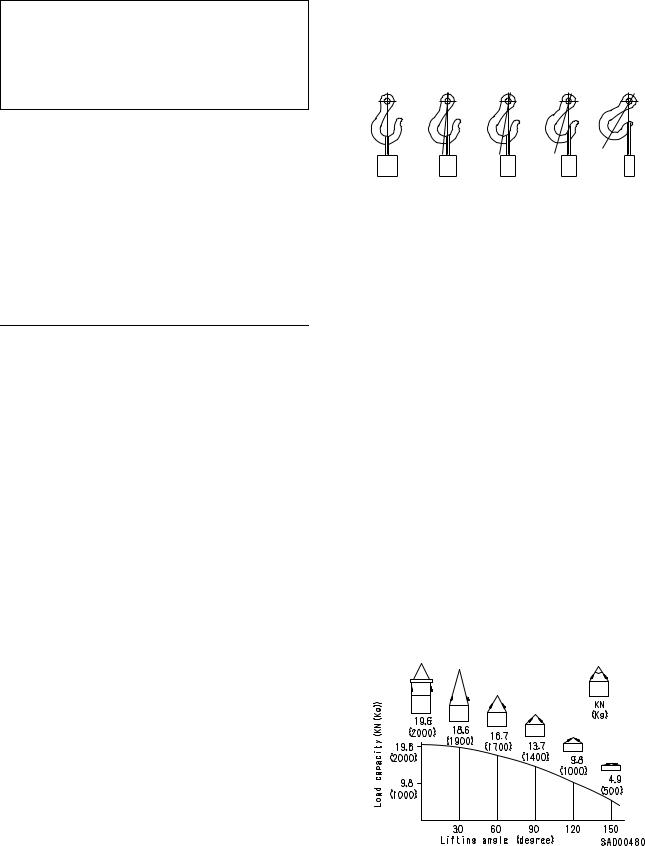
2)Sling wire ropes from the middle portion of the hook.
Slinging near the edge of the hook may cause the rope to slip off the hook during hoisting, and a serious accident can result. Hooks have maximum strength at the middle portion.
|
100% |
88% |
79% |
71% |
41% |
SAD00479
3)Do not sling a heavy load with one rope alone, but sling with two or more ropes symmetrically wound onto the load.
¤Slinging with one rope may cause turning of the load during hoisting, untwisting of the rope, or slipping of the rope from its original winding position on the load, which can result in a dangerous accident.
4)Do not sling a heavy load with ropes forming a wide hanging angle from the hook.
When hoisting a load with two or more ropes, the force subjected to each rope will increase with the hanging angles. The table below shows the variation of allowable load kN {kg} when hoisting is made with two ropes, each of which is allowed to sling up to 9.8 kN {1000 kg} vertically, at various hanging angles.
When two ropes sling a load vertically, up to 19.6 kN {2000 kg} of total weight can be suspended. This weight becomes 9.8 kN {1000 kg} when two ropes make a 120° hanging angle. On the other hand, two ropes are subjected to an excessive force as large as 39.2 kN {4000 kg} if they sling a 19.6 kN {2000 kg} load at a lifting angle of 150°.
00-7
![]()
FOREWORD METHOD OF DISASSEMBLING, CONNECTING PUSH-PULL TYPE COUPLER
METHOD OF DISASSEMBLING, CONNECTING PUSH-PULL TYPE COUPLER
|
¤Before carrying out the following work, release |
Type 1 |
|
the residual pressure from the hydraulic tank. |
|
|
For details, see TESTING AND ADJUSTING, |
|
|
Releasing residual pressure from hydraulic |
|
|
tank. |
|
|
¤Even if the residual pressure is released from |
|
|
the hydraulic tank, some hydraulic oil flows out |
|
|
when the hose is disconnected. Accordingly, |
|
|
prepare an oil receiving container. |
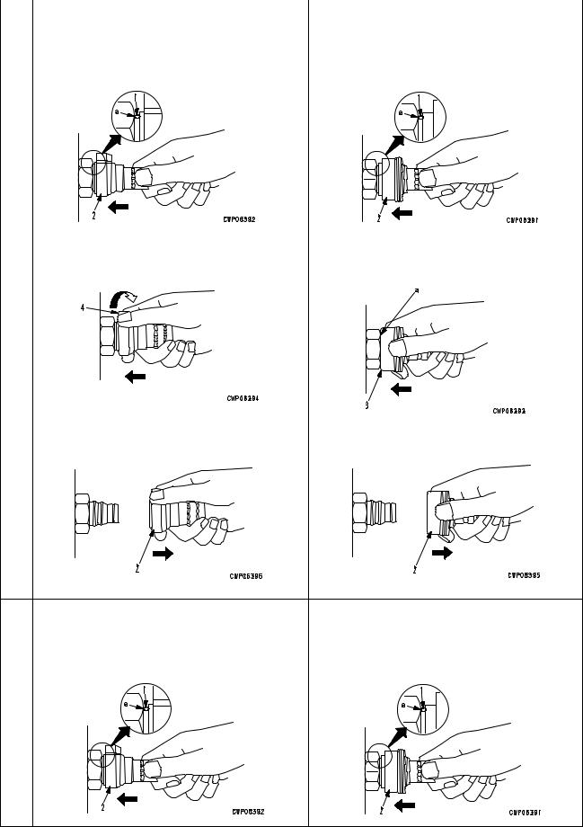
Disconnection
1)Release the residual pressure from the hydraulic tank. For details , see TES TIN G AN D ADJUSTING, Releasing residual pressure from hydraulic tank.
2)Hold adapter (1) and push hose joint (2) into mating adapter (3). (See Fig. 1)
The adapter can be pushed in about 3.5 mm.
Do not hold rubber cap portion (4).
3)After hose joint (2) is pushed into adapter (3), press rubber cap portion (4) against (3) until it clicks. (See Fig. 2)
4)Hold hose adapter (1) or hose (5) and pull it out. (See Fig. 3)
Since some hydraulic oil flows out, prepare an oil receiving container.
Connection
1)Hold hose adapter (1) or hose (5) and insert it in mating adapter (3), aligning them with each other. (See Fig. 4)
Do not hold rubber cap portion (4).
2)After inserting the hose in the mating adapter
perfectly, pull it back to check its connecting condition. (See Fig. 5)
When the hose is pulled back, the rubber cap portion moves toward the hose about 3.5 mm. This does not indicate abnormality, however.
00-8
|
FOREWORD |
METHOD OF DISASSEMBLING, CONNECTING PUSH-PULL TYPE COUPLER |
|
|
Type 2 |
Type 3 |
|
|
1) Hold the mouthpiece of the tightening portion |
1) Hold the mouthpiece of the tightening portion |
|
|
and push body (2) in straight until sliding pre- |
and push body (2) in straight until sliding pre- |
|
|
vention ring (1) contacts contact surface a of |
vention ring (1) contacts contact surface a of |
|
|
the hexagonal portion at the male end. |
the hexagonal portion at the male end. |
|
2) Hold in the condition in Step 1), and turn |
2) Hold in the condition in Step 1), and push |
|
lever (4) to the right (clockwise). |
until cover (3) contacts contact surface a of |
|
the hexagonal portion at the male end. |
Disassembly
|
3) Hold in the condition in Steps 1) and 2), and |
3) Hold in the condition in Steps 1) and 2), and |
|
pull out whole body (2) to disconnect it. |
pull out whole body (2) to disconnect it. |
|
• Hold the mouthpiece of the tightening portion • |
Hold the mouthpiece of the tightening portion |
|
and push body (2) in straight until sliding pre- |
and push body (2) in straight until sliding pre- |
|
vention ring (1) contacts contact surface a of |
vention ring (1) contacts contact surface a of |
|
the hexagonal portion at the male end to con- |
the hexagonal portion at the male end to con- |
|
nect it. |
nect it. |
Connection
00-9
|
FOREWORD |
COATING MATERIALS |
COATING MATERIALS
The recommended coating materials such as adhesives, gasket sealants and greases used for disassembly and assembly are listed below.
For coating materials not listed below, use the equivalent of products shown in this list.
|
Category |
Komatsu code |
Part No. |
Q’ty |
Container |
Main applications, featuresr |
||||
|
• Used to prevent rubber gaskets, |
|||||||||
|
LT-1A |
790-129-9030 |
150 g |
Tube |
rubber cushions, and cock plug |
|||||
|
from coming out. |
|||||||||
|
• Used in places requiring an imme- |
|||||||||
|
diately effective, strong adhesive. |
|||||||||
|
LT-1B |
790-129-9050 |
20 g |
Polyethylene |
Used for plastics (except polyeth- |
|||||
|
(2 pcs.) |
container |
ylene, polyprophylene, tetrafluor- |
|||||||
|
oethlene and vinyl chloride), |
|||||||||
|
rubber, metal and non-metal. |
|||||||||
|
• Features: Resistance to heat and |
|||||||||
|
LT-2 |
09940-00030 |
50 g |
Polyethylene |
chemicals |
|||||
|
container |
• |
Used for anti-loosening and seal- |
|||||||
|
ant purpose for bolts and plugs. |
|||||||||
|
790-129-9060 |
Adhesive: |
• Used as adhesive or sealant for |
|||||||
|
1 kg |
metal, glass and plastic. |
||||||||
|
(Set of |
Hardenin |
Can |
|||||||
|
LT-3 |
adhesive and |
||||||||
|
g |
|||||||||
|
hardening |
|||||||||
|
agent: |
|||||||||
|
agent) |
|||||||||
|
Adhesives |
500 g |
||||||||
|
LT-4 |
790-129-9040 |
250 g |
Polyethylene |
• |
Used |
as |
sealant |
for machined |
|
|
container |
holes. |
||||||||
|
Holtz |
790-126-9120 |
75 g |
Tube |
• |
Used as heat-resisting sealant for |
||||
|
MH 705 |
repairing engine. |
||||||||
|
• Quick hardening type adhesive |
|||||||||
|
Three bond |
790-129-9140 |
50 g |
Polyethylene |
• |
Cure time: within 5 sec. to 3 min. |
||||
|
1735 |
container |
• |
Used mainly for adhesion of met- |
||||||
|
als, rubbers, plastics and woods. |
|||||||||
|
• Quick hardening type adhesive |
|||||||||
|
Aron-alpha |
Polyethylene |
• Quick cure type (max. strength af- |
|||||||
|
790-129-9130 |
2 g |
ter 30 minutes) |
|||||||
|
201 |
container |
||||||||
|
• Used mainly for adhesion of rub- |
|||||||||
|
bers, plastics and metals. |
|||||||||
|
Loctite |
Polyethylene |
• Resistance to heat, chemicals |
|||||||
|
79A-129-9110 |
50 cc |
• Used at joint portions subject to |
|||||||
|
648-50 |
container |
||||||||
|
high temperatures. |
|||||||||
|
• Used as adhesive or sealant for |
|||||||||
|
LG-1 |
790-129-9010 |
200 g |
Tube |
gaskets and packing of power |
|||||
|
train case, etc. |
|||||||||
|
• Used |
as |
sealant |
for various |
||||||
|
threads, pipe joints, flanges. |
|||||||||
|
LG-5 |
790-129-9070 |
1 kg |
Can |
• |
Used as sealant for tapered |
||||
|
Gasket |
plugs, elbows, nipples of hydrau- |
||||||||
|
sealant |
lic piping. |
||||||||
|
• |
Features: Silicon based, resist- |
||||||||
|
ance to heat, cold |
|||||||||
|
LG-6 |
790-129-9020 |
200 g |
Tube |
• Used as sealant for flange sur- |
|||||
|
face, tread. |
|||||||||
|
• mab Used as sealant for oil pan, |
|||||||||
|
final drive case, etc. |
|||||||||
00-10
|
FOREWORD |
COATING MATERIALS |
|
Category |
Komatsu code |
Part No. |
Q’ty |
Container |
Main applications, featuresr |
|
|
• Ftures: Silicon based, quick hard- |
||||||
|
ening type |
||||||
|
LG-7 |
790-129-9070 |
1 g |
Tube |
• |
Used as sealant for flywheel |
|
|
Adhesives |
housing, intake manifold, oil an, |
|||||
|
thermostat housing, etc. |
||||||
|
Three bond |
790-129-9090 |
100 g |
Tube |
• Used as heat-resisting sealant for |
||
|
1211 |
repairing engine. |
|||||
|
LM-G |
09940-00051 |
60 g |
Can |
• Used as lubricant for sliding por- |
||
|
tion (to prevent from squeaking). |
||||||
|
Molybdenum |
||||||
|
• Used to prevent seizure or scuf- |
||||||
|
disulphide |
||||||
|
fling of the thread when press fit- |
||||||
|
lubricant |
||||||
|
LM-P |
09940-00040 |
200 g |
Tube |
ting or shrink fitting. |
||
|
• Used as lubricant for linkage, |
||||||
|
bearings, etc. |
||||||
|
SYG2-400LI |
• |
General purpose type |
||||
|
SYG2-350LI |
||||||
|
G2-LI |
SYG2-400LI-A |
Various |
Various |
|||
|
SYG2-160LI |
||||||
|
SYGA-160CNLI |
||||||
|
SYG2-400CA |
• |
Used for normal temperature, |
||||
|
Grease |
SYG2-350CA |
light load bearing at places in con- |
||||
|
G2-CA |
SYG2-400CA-A |
Various |
Various |
tact with water or steam. |
||
|
SYG2-160CA |
||||||
|
SYGA-160CNCA |
||||||
|
Molybdenum |
400 g |
• Used for places with heavy load |
||||
|
disulphide |
SYG2-400M |
(10 per |
Belows type |
|||
|
lubricant |
case) |
|||||
00-11
|
FOREWORD |
STANDARD TIGHTENING TORQUE |
STANDARD TIGHTENING TORQUE
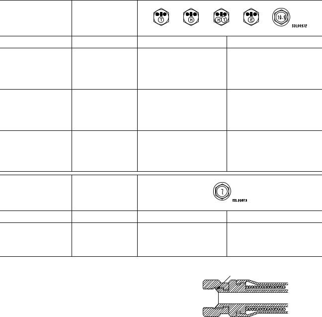
STANDARD TIGHTENING TORQUE TABLE (WHEN USING TORQUE WRENCH)
In the case of metric nuts and bolts for which there is no special instruction, tighten to the torque given in the table below.
|
Thread diameter |
Width across |
||||||
|
of bolt |
flats |
||||||
|
mm |
mm |
Nm |
kgm |
||||
|
6 |
10 |
13.2 |
0 |
1.4 |
1.35 |
0 |
0.15 |
|
8 |
13 |
31 0 3 |
3.2 |
0 |
0.3 |
||
|
10 |
17 |
66 0 7 |
6.7 |
0 |
0.7 |
||
|
12 |
19 |
113 0 10 |
11.5 0 1 |
||||
|
14 |
22 |
177 0 19 |
18 0 2 |
||||
|
16 |
24 |
279 0 30 |
28.5 0 3 |
||||
|
18 |
27 |
382 0 39 |
39 0 4 |
||||
|
20 |
30 |
549 0 59 |
56 0 6 |
||||
|
22 |
32 |
745 0 83 |
76 0 8.5 |
||||
|
24 |
36 |
927 0 103 |
94.5 |
0 |
10.5 |
||
|
27 |
41 |
1320 0 140 |
135 0 15 |
||||
|
30 |
46 |
1720 0 190 |
175 0 20 |
||||
|
33 |
50 |
2210 0 240 |
225 0 25 |
||||
|
36 |
55 |
2750 0 290 |
280 0 30 |
||||
|
39 |
60 |
3290 0 340 |
335 0 35 |
||||
|
Thread diameter |
Width across |
||||||
|
of bolt |
flats |
||||||
|
mm |
mm |
Nm |
kgm |
||||
|
6 |
10 |
7.85 0 1.95 |
0.8 |
0 |
0.2 |
||
|
8 |
13 |
18.6 0 4.9 |
1.9 |
0 |
0.5 |
||
|
10 |
14 |
40.2 0 5.9 |
4.1 |
0 |
0.6 |
||
|
12 |
27 |
82.35 0 7.85 |
8.4 |
0 |
0.8 |
Sealing surface
TABLE OF TIGHTENING TORQUES FOR FLARED NUTS
In the case of flared nuts for which there is no special instruction, tighten to the torque given in
|
the table below. |
SAD00483 |
|||||
|
Thread diameter |
Width across flat |
Tightening torque |
||||
|
mm |
mm |
Nm |
kgm |
|||
|
14 |
19 |
24.5 |
0 |
4.9 |
2.5 0 0.5 |
|
|
18 |
24 |
49 0 19.6 |
5 0 2 |
|||
|
22 |
27 |
78.5 0 19.6 |
8 0 2 |
|||
|
24 |
32 |
137.3 |
0 |
29.4 |
14 0 3 |
|
|
30 |
36 |
176.5 |
0 |
29.4 |
18 0 3 |
|
|
33 |
41 |
196.1 0 49 |
20 0 5 |
|||
|
36 |
46 |
245.2 0 49 |
25 0 5 |
|||
|
42 |
55 |
294.2 0 49 |
30 0 5 |
|||
00-12
|
FOREWORD |
STANDARD TIGHTENING TORQUE |
TABLE OF TIGHTENING TORQUES FOR SPLIT FLANGE BOLTS
In the case of split flange bolts for which there is no special instruction, tighten to the torque given in the table below.
|
Thread diameter |
Width across flat |
Tightening torque |
||||
|
mm |
mm |
Nm |
kgm |
|||
|
10 |
14 |
65.7 |
0 |
6.8 |
6.7 0 0.7 |
|
|
12 |
17 |
112 0 9.8 |
11.5 0 1 |
|||
|
16 |
22 |
279 |
0 |
29 |
28.5 0 3 |
|
TABLE OF TIGHTENING TORQUES FOR O-RING BOSS PIPING JOINTS
Unless there are special instructions, tighten the O-ring boss piping joints to the torque below.
|
Thread diameter |
Width across flat |
Tightening torque |
||||||
|
Norminal No. |
||||||||
|
mm |
mm |
Nm |
kgm |
|||||
|
02 |
14 |
34.3 |
0 |
4.9 |
3.5 |
0 |
0.5 |
|
|
03, 04 |
20 |
Varies depending |
93.1 |
0 |
9.8 |
9.5 0 1 |
||
|
05, 06 |
24 |
on type of |
142.1 |
0 |
19.6 |
14.5 0 2 |
||
|
10, 12 |
33 |
connector. |
421.4 |
0 |
58.8 |
43 0 6 |
||
|
14 |
42 |
877.1 0 132.3 |
89.5 |
0 |
13.5 |
|||
TABLE OF TIGHTENING TORQUES FOR O-RING BOSS PLUGS
Unless there are special instructions, tighten the O-ring boss plugs to the torque below.
|
Thread diameter |
Width across flat |
Tightening torque |
|||||
|
Norminal No. |
|||||||
|
mm |
mm |
Nm |
kgm |
||||
|
08 |
08 |
14 |
7.35 0 1.47 |
0.75 |
0 0.15 |
||
|
10 |
10 |
17 |
11.27 0 |
1.47 |
1.15 |
0 0.15 |
|
|
12 |
12 |
19 |
17.64 |
0 |
1.96 |
1.8 |
0 0.2 |
|
14 |
14 |
22 |
22.54 |
0 |
1.96 |
2.3 |
0 0.2 |
|
16 |
16 |
24 |
29.4 |
0 |
4.9 |
3 0 0.5 |
|
|
18 |
18 |
27 |
39.2 |
0 |
4.9 |
4 0 0.5 |
|
|
20 |
20 |
30 |
49 0 4.9 |
5 0 0.5 |
|||
|
24 |
24 |
32 |
68.6 |
0 |
9.8 |
7 |
0 1 |
|
30 |
30 |
32 |
107.8 |
0 |
14.7 |
11 0 1.5 |
|
|
33 |
33 |
n |
127.4 |
0 |
19.6 |
13 0 2 |
|
|
36 |
36 |
36 |
151.9 |
0 |
24.5 |
15.5 0 2.5 |
|
|
42 |
42 |
n |
210.7 |
0 |
29.4 |
21.5 0 3 |
|
|
52 |
52 |
n |
323.4 |
0 |
44.1 |
33 0 4.5 |
|
00-13
|
FOREWORD |
STANDARD TIGHTENING TORQUE |
TIGHTENING TORQUE FOR 102 ENGINE SERIES
1)BOLT AND NUTS
Use these torques for bolts and nuts (unit: mm) of Cummins Engine.
|
Thread diameter |
Tightening torque |
||
|
mm |
Nm |
kgm |
|
|
6 |
10 0 2 |
1.02 0 0.20 |
|
|
8 |
24 0 4 |
2.45 0 0.41 |
|
|
10 |
43 0 6 |
4.38 0 0.61 |
|
|
12 |
77 0 12 |
7.85 0 1.22 |
|
2)EYE JOINTS
Use these torques for eye joints (unit: mm) of Cummins Engine.
|
Thread diameter |
Tightening torque |
||
|
mm |
Nm |
kgm |
|
|
6 |
8 0 2 |
0.81 0 0.20 |
|
|
8 |
10 0 2 |
1.02 0 0.20 |
|
|
10 |
12 0 2 |
1.22 0 0.20 |
|
|
12 |
24 0 4 |
2.45 0 0.41 |
|
|
14 |
36 0 5 |
3.67 0 0.51 |
|
3)TAPERED SCREWS
Use these torques for tapered screws (unit: inch) of Cummins Engine.
|
Thread diameter |
Tightening torque |
||
|
inch |
Nm |
kgm |
|
|
1 / 16 |
3 0 1 |
0.31 0 0.10 |
|
|
1 / 8 |
8 0 2 |
0.81 0 0.20 |
|
|
1 / 4 |
12 0 2 |
1.22 0 0.20 |
|
|
3 / 8 |
15 0 2 |
1.53 0 0.41 |
|
|
1 / 2 |
24 0 4 |
2.45 0 0.41 |
|
|
3 / 4 |
36 0 5 |
3.67 0 0.51 |
|
|
1 |
60 0 9 |
6.12 0 0.92 |
|
TIGHTENING TORQUE TABLE FOR HOSES (TAPER SEAL TYPE AND FACE SEAL TYPE)
Tighten the hoses (taper seal type and face seal type) to the following torque, unless otherwise specified.
Apply the following torque when the threads are coated (wet) with engine oil.
|
Tightening torque (Nm {kgm}) |
Taper seal |
Face seal type |
||||||
|
type |
||||||||
|
Nominal size |
Width across |
|||||||
|
of hose |
flats |
Range |
Target |
Thread size |
Nominal thread |
Root diameter |
||
|
size — Threads per |
||||||||
|
(mm) |
inch, Thread series |
(mm) (Reference) |
||||||
|
02 |
19 |
35 — 63 {3.5 — 6.5} |
44 {4.5} |
14 |
9 |
— 18UNF |
14.3 |
|
|
– |
||||||||
|
16 |
||||||||
|
22 |
54 — 93 {5.5 — 9.5} |
74 {4.5} |
– |
11 |
— 16UN |
17.5 |
||
|
03 |
– |
|||||||
|
16 |
||||||||
|
24 |
59 — 98 {6.0 — 10.0} |
78 {8.0} |
18 |
– |
– |
|||
|
04 |
27 |
84 |
— 132 {8.5 — 13.5} |
103 {10.5} |
22 |
13 |
— 16UN |
20.7 |
|
– |
||||||||
|
16 |
||||||||
|
05 |
32 |
128 |
— 186 {13.0 — 19.0} |
157 {16.0} |
24 |
1 — 14UNS |
25.4 |
|
|
06 |
36 |
177 |
— 245 {18.0 — 25.0} |
216 {22.0} |
30 |
3 |
— 12UNF |
30.3 |
|
1 – |
||||||||
|
16 |
||||||||
|
(10) |
41 |
177 |
— 245 {18.0 — 25.0} |
216 {22.0} |
33 |
– |
– |
|
|
(12) |
46 |
197 |
— 294 {20.0 — 30.0} |
245 {25.0} |
36 |
– |
– |
|
|
(14) |
55 |
246 |
— 343 {25.0 — 35.0} |
294 {30.0} |
42 |
– |
– |
|
00-14

|
FOREWORD |
ELECTRIC WIRE CODE |
ELECTRIC WIRE CODE
In the wiring diagrams, various colors and symbols are employed to indicate the thickness of wires. This wire code table will help you understand WIRING DIAGRAMS.
Example: 5WB indicates a cable having a nominal number 5 and white coating with black stripe.
CLASSIFICATION BY THICKNESS
|
Copper wire |
|||||||
|
Norminal |
Cable O.D. |
Current |
|||||
|
Dia. of |
Cross |
rating |
Applicable circuit |
||||
|
number |
Number of |
(mm) |
|||||
|
(A) |
|||||||
|
strands |
section |
||||||
|
strands |
(mm2) |
(mm2) |
|||||
|
0.85 |
11 |
0.32 |
0.88 |
2.4 |
12 |
Starting, lighting, signal |
|
|
etc. |
|||||||
|
2 |
26 |
0.32 |
2.09 |
3.1 |
20 |
Lighting, signal etc. |
|
|
5 |
65 |
0.32 |
5.23 |
4.6 |
37 |
Charging and signal |
|
|
15 |
84 |
0.45 |
13.36 |
7.0 |
59 |
Starting (Glow plug) |
|
|
40 |
85 |
0.80 |
42.73 |
11.4 |
135 |
Starting |
|
|
60 |
127 |
0.80 |
63.84 |
13.6 |
178 |
Starting |
|
|
100 |
217 |
0.80 |
109.1 |
17.6 |
230 |
Starting |
|
CLASSIFICATION BY COLOR AND CODE
|
Priori- |
Circuits |
|||||||||
|
Charging |
Ground |
Starting |
Lighting |
Instrument |
Signal |
Other |
||||
|
ty |
Classi- |
|||||||||
|
fication |
||||||||||
|
Pri- |
Code |
W |
B |
B |
R |
Y |
G |
L |
||
|
1 |
||||||||||
|
mary |
Color |
White |
Black |
Black |
Red |
Yellow |
Green |
Blue |
||
|
Code |
WR |
BW |
RW |
YR |
GW |
LW |
||||
|
2 |
||||||||||
|
Color |
White & Red |
White & Black |
Red & White |
Rellow & Red |
Green & White |
Blue & White |
||||
|
Code |
WB |
BY |
RB |
YB |
GR |
LR |
||||
|
3 |
||||||||||
|
Color |
White & Black |
Black & Yellow |
Red & Black |
Yellow & Black |
Green & Red |
Blue & Yellow |
||||
|
Code |
WL |
BR |
RY |
YG |
GY |
LY |
||||
|
4 |
Auxi- |
|||||||||
|
liary |
Yellow & |
Green & |
||||||||
|
Color |
White & Blue |
Black & Red |
Red & Yellow |
Blue & Yellow |
||||||
|
Green |
Yellow |
|||||||||
|
Code |
WG |
RG |
YL |
GB |
LB |
|||||
|
5 |
||||||||||
|
Color |
White & Green |
Red & Green |
Yellow & Blue |
Green & Black |
Blue & Black |
|||||
|
Code |
RL |
YW |
GL |
|||||||
|
6 |
||||||||||
|
Color |
Red & Blue |
Yellow & White |
Green & Blue |
|||||||
00-15

|
FOREWORD |
CONVERSION TABLE |
CONVERSION TABLE
METHOD OF USING THE CONVERSION TABLE
The Conversion Table in this section is provided to enable simple conversion of figures. For details of the method of using the Conversion Table, see the example given below.
EXAMPLE
•Method of using the Conversion Table to convert from millimeters to inches
1.Convert 55 mm into inches.
(1)Locate the number 50 in the vertical column at the left side, take this as A, then draw a horizontal line from A.
(2)Locate the number 5 in the row across the top, take this as B, then draw a perpendicular line down from B.
(3)Take the point where the two lines cross as C. This point C gives the value when converting from millimeters to inches. Therefore, 55 mm = 2.165 inches.
2.Convert 550 mm into inches.
(1)The number 550 does not appear in the table, so divide by 10 (move the decimal point one place to the left) to convert it to 55 mm.
(2)Carry out the same procedure as above to convert 55 mm to 2.165 inches.
(3)The original value (550 mm) was divided by 10, so multiply 2.165 inches by 10 (move the decimal point one place to the right) to return to the original value. This gives 550 mm = 21.65 inches.
B
Millimeters to inches
|
1 mm = 0.03937 in |
|||||||||||||
|
0 |
1 |
2 |
3 |
4 |
5 |
6 |
7 |
8 |
9 |
||||
|
0 |
0 |
0.039 |
0.079 |
0.118 |
0.157 |
0.197 |
0.236 |
0.276 |
0.315 |
0.354 |
|||
|
10 |
0.394 |
0.433 |
0.472 |
0.512 |
0.551 |
0.591 |
0.630 |
0.669 |
0.709 |
0.748 |
|||
|
20 |
0.787 |
0.827 |
0.866 |
0.906 |
0.945 |
0.984 |
1.024 |
1.063 |
1.102 |
1.142 |
|||
|
30 |
1.181 |
1.220 |
1.260 |
1.299 |
1.339 |
1.378 |
1.417 |
1.457 |
1.496 |
1.536 |
|||
|
40 |
1.575 |
1.614 |
1.654 |
1.693 |
1.732 |
1.772 |
1.811 |
1.850 |
1.890 |
1.929 |
|||
|
C |
|||||||||||||
|
2.205 |
2.244 |
2.283 |
2.323 |
||||||||||
|
A |
50 |
1.969 |
2.008 |
2.047 |
2.087 |
2.126 |
2.165 |
||||||
|
60 |
2.362 |
2.402 |
2.441 |
2.480 |
2.520 |
2.559 |
2.598 |
2.638 |
2.677 |
2.717 |
|||
|
70 |
2.756 |
2.795 |
2.835 |
2.874 |
2.913 |
2.953 |
2.992 |
3.032 |
3.071 |
3.110 |
|||
|
80 |
3.150 |
3.189 |
3.228 |
3.268 |
3.307 |
3.346 |
3.386 |
3.425 |
3.465 |
3.504 |
|||
|
90 |
3.543 |
3.583 |
3.622 |
3.661 |
3.701 |
3.740 |
3.780 |
3.819 |
3.858 |
3.898 |
|||
00-16

|
FOREWORD |
CONVERSION TABLE |
|||||||||
|
Millimeters to Inches |
||||||||||
|
1 mm = 0.03937 in |
||||||||||
|
0 |
1 |
2 |
3 |
4 |
5 |
6 |
7 |
8 |
9 |
|
|
0 |
0 |
0.039 |
0.079 |
0.118 |
0.157 |
0.197 |
0.236 |
0.276 |
0.315 |
0.354 |
|
10 |
0.394 |
0.433 |
0.472 |
0.512 |
0.551 |
0.591 |
0.630 |
0.669 |
0.709 |
0.748 |
|
20 |
0.787 |
0.827 |
0.866 |
0.906 |
0.945 |
0.984 |
1.024 |
1.063 |
1.102 |
1.142 |
|
30 |
1.181 |
1.220 |
1.260 |
1.299 |
1.339 |
1.378 |
1.417 |
1.457 |
1.496 |
1.536 |
|
40 |
1.575 |
1.614 |
1.654 |
1.693 |
1.732 |
1.772 |
1.811 |
1.850 |
1.890 |
1.929 |
|
50 |
1.969 |
2.008 |
2.047 |
2.087 |
2.126 |
2.165 |
2.205 |
2.244 |
2.283 |
2.323 |
|
60 |
2.362 |
2.402 |
2.441 |
2.480 |
2.520 |
2.559 |
2.598 |
2.638 |
2.677 |
2.717 |
|
70 |
2.756 |
2.795 |
2.835 |
2.874 |
2.913 |
2.953 |
2.992 |
3.032 |
3.071 |
3.110 |
|
80 |
3.150 |
3.189 |
3.228 |
3.268 |
3.307 |
3.346 |
3.386 |
3.425 |
3.465 |
3.504 |
|
90 |
3.543 |
3.583 |
3.622 |
3.661 |
3.701 |
3.740 |
3.780 |
3.819 |
3.858 |
3.898 |
Kilogram to Pound
1 kg = 2.2046 lb
|
0 |
1 |
2 |
3 |
4 |
5 |
6 |
7 |
8 |
9 |
|
|
0 |
0 |
2.20 |
4.41 |
6.61 |
8.82 |
11.02 |
13.23 |
15.43 |
17.64 |
19.84 |
|
10 |
22.05 |
24.25 |
26.46 |
28.66 |
30.86 |
33.07 |
35.27 |
37.48 |
39.68 |
41.89 |
|
20 |
44.09 |
46.30 |
48.50 |
50.71 |
51.91 |
55.12 |
57.32 |
59.53 |
61.73 |
63.93 |
|
30 |
66.14 |
68.34 |
70.55 |
72.75 |
74.96 |
77.16 |
79.37 |
81.57 |
83.78 |
85.98 |
|
40 |
88.18 |
90.39 |
92.59 |
94.80 |
97.00 |
99.21 |
101.41 |
103.62 |
105.82 |
108.03 |
|
50 |
110.23 |
112.44 |
114.64 |
116.85 |
119.05 |
121.25 |
123.46 |
125.66 |
127.87 |
130.07 |
|
60 |
132.28 |
134.48 |
136.69 |
138.89 |
141.10 |
143.30 |
145.51 |
147.71 |
149.91 |
152.12 |
|
70 |
154.32 |
156.53 |
158.73 |
160.94 |
163.14 |
165.35 |
167.55 |
169.76 |
171.96 |
174.17 |
|
80 |
176.37 |
178.57 |
180.78 |
182.98 |
185.19 |
187.39 |
189.60 |
191.80 |
194.01 |
196.21 |
|
90 |
198.42 |
200.62 |
202.83 |
205.03 |
207.24 |
209.44 |
211.64 |
213.85 |
216.05 |
218.26 |
00-17
![]()
|
FOREWORD |
CONVERSION TABLE |
|||||||||
|
Liter to U.S. Gallon |
||||||||||
|
1l = 0.2642 U.S. Gal |
||||||||||
|
0 |
1 |
2 |
3 |
4 |
5 |
6 |
7 |
8 |
9 |
|
|
0 |
0 |
0.264 |
0.528 |
0.793 |
1.057 |
1.321 |
1.585 |
1.849 |
2.113 |
2.378 |
|
10 |
2.642 |
2.906 |
3.170 |
3.434 |
3.698 |
3.963 |
4.227 |
4.491 |
4.755 |
5.019 |
|
20 |
5.283 |
5.548 |
5.812 |
6.076 |
6.340 |
6.604 |
6.869 |
7.133 |
7.397 |
7.661 |
|
30 |
7.925 |
8.189 |
8.454 |
8.718 |
8.982 |
9.246 |
9.510 |
9.774 |
10.039 |
10.303 |
|
40 |
10.567 |
10.831 |
11.095 |
11.359 |
11.624 |
11.888 |
12.152 |
12.416 |
12.680 |
12.944 |
|
50 |
13.209 |
13.473 |
13.737 |
14.001 |
14.265 |
14.529 |
14.795 |
15.058 |
15.322 |
15.586 |
|
60 |
15.850 |
16.115 |
16.379 |
16.643 |
16.907 |
17.171 |
17.435 |
17.700 |
17.964 |
18.228 |
|
70 |
18.492 |
18.756 |
19.020 |
19.285 |
19.549 |
19.813 |
20.077 |
20.341 |
20.605 |
20.870 |
|
80 |
21.134 |
21.398 |
21.662 |
21.926 |
22.190 |
22.455 |
22.719 |
22.983 |
23.247 |
23.511 |
|
90 |
23.775 |
24.040 |
24.304 |
24.568 |
24.832 |
25.096 |
25.361 |
25.625 |
25.889 |
26.153 |
Liter to U.K. Gallon
1l = 0.21997 U.K. Gal
|
0 |
1 |
2 |
3 |
4 |
5 |
6 |
7 |
8 |
9 |
|
|
0 |
0 |
0.220 |
0.440 |
0.660 |
0.880 |
1.100 |
1.320 |
1.540 |
1.760 |
1.980 |
|
10 |
2.200 |
2.420 |
2.640 |
2.860 |
3.080 |
3.300 |
3.520 |
3.740 |
3.950 |
4.179 |
|
20 |
4.399 |
4.619 |
4.839 |
5.059 |
5.279 |
5.499 |
5.719 |
5.939 |
6.159 |
6.379 |
|
30 |
6.599 |
6.819 |
7.039 |
7.259 |
7.479 |
7.969 |
7.919 |
8.139 |
8.359 |
8.579 |
|
40 |
8.799 |
9.019 |
9.239 |
9.459 |
9.679 |
9.899 |
10.119 |
10.339 |
10.559 |
10.778 |
|
50 |
10.998 |
11.281 |
11.438 |
11.658 |
11.878 |
12.098 |
12.318 |
12.528 |
12.758 |
12.978 |
|
60 |
13.198 |
13.418 |
13.638 |
13.858 |
14.078 |
14.298 |
14.518 |
14.738 |
14.958 |
15.178 |
|
70 |
15.398 |
15.618 |
15.838 |
16.058 |
16.278 |
16.498 |
16.718 |
16.938 |
17.158 |
17.378 |
|
80 |
17.598 |
17.818 |
18.037 |
18.257 |
18.477 |
18.697 |
18.917 |
19.137 |
19.357 |
19.577 |
|
90 |
19.797 |
20.017 |
20.237 |
20.457 |
20.677 |
20.897 |
21.117 |
21.337 |
21.557 |
21.777 |
00-18

|
FOREWORD |
CONVERSION TABLE |
|||||||||
|
kgm to ft. lb |
||||||||||
|
1 kgm = 7.233 ft. lb |
||||||||||
|
0 |
1 |
2 |
3 |
4 |
5 |
6 |
7 |
8 |
9 |
|
|
0 |
0 |
7.2 |
14.5 |
21.7 |
28.9 |
36.2 |
43.4 |
50.6 |
57.9 |
65.1 |
|
10 |
72.3 |
79.6 |
86.8 |
94.0 |
101.3 |
108.5 |
115.7 |
123.0 |
130.2 |
137.4 |
|
20 |
144.7 |
151.9 |
159.1 |
166.4 |
173.6 |
180.8 |
188.1 |
195.3 |
202.5 |
209.8 |
|
30 |
217.0 |
224.2 |
231.5 |
238.7 |
245.9 |
253.2 |
260.4 |
267.6 |
274.9 |
282.1 |
|
40 |
289.3 |
296.6 |
303.8 |
311.0 |
318.3 |
325.5 |
332.7 |
340.0 |
347.2 |
354.4 |
|
50 |
361.7 |
368.9 |
376.1 |
383.4 |
390.6 |
397.8 |
405.1 |
412.3 |
419.5 |
426.8 |
|
60 |
434.0 |
441.2 |
448.5 |
455.7 |
462.9 |
470.2 |
477.4 |
484.6 |
491.8 |
499.1 |
|
70 |
506.3 |
513.5 |
520.8 |
528.0 |
535.2 |
542.5 |
549.7 |
556.9 |
564.2 |
571.4 |
|
80 |
578.6 |
585.9 |
593.1 |
600.3 |
607.6 |
614.8 |
622.0 |
629.3 |
636.5 |
643.7 |
|
90 |
651.0 |
658.2 |
665.4 |
672.7 |
679.9 |
687.1 |
694.4 |
701.6 |
708.8 |
716.1 |
|
100 |
723.3 |
730.5 |
737.8 |
745.0 |
752.2 |
759.5 |
766.7 |
773.9 |
781.2 |
788.4 |
|
110 |
795.6 |
802.9 |
810.1 |
817.3 |
824.6 |
831.8 |
839.0 |
846.3 |
853.5 |
860.7 |
|
120 |
868.0 |
875.2 |
882.4 |
889.7 |
896.9 |
904.1 |
911.4 |
918.6 |
925.8 |
933.1 |
|
130 |
940.3 |
947.5 |
954.8 |
962.0 |
969.2 |
976.5 |
983.7 |
990.9 |
998.2 |
1005.4 |
|
140 |
1012.6 |
1019.9 |
1027.1 |
1034.3 |
1041.5 |
1048.8 |
1056.0 |
1063.2 |
1070.5 |
1077.7 |
|
150 |
1084.9 |
1092.2 |
1099.4 |
1106.6 |
1113.9 |
1121.1 |
1128.3 |
1135.6 |
1142.8 |
1150.0 |
|
160 |
1157.3 |
1164.5 |
1171.7 |
1179.0 |
1186.2 |
1193.4 |
1200.7 |
1207.9 |
1215.1 |
1222.4 |
|
170 |
1129.6 |
1236.8 |
1244.1 |
1251.3 |
1258.5 |
1265.8 |
1273.0 |
1280.1 |
1287.5 |
1294.7 |
|
180 |
1301.9 |
1309.2 |
1316.4 |
1323.6 |
1330.9 |
1338.1 |
1345.3 |
1352.6 |
1359.8 |
1367.0 |
|
190 |
1374.3 |
1381.5 |
1388.7 |
1396.0 |
1403.2 |
1410.4 |
1417.7 |
1424.9 |
1432.1 |
1439.4 |
00-19

|
FOREWORD |
CONVERSION TABLE |
||||||||||
|
kg/cm2 to lb/in2 |
|||||||||||
|
1kg/cm2 = 14.2233 lb/in2 |
|||||||||||
|
0 |
1 |
2 |
3 |
4 |
5 |
6 |
7 |
8 |
9 |
||
|
0 |
0 |
14.2 |
28.4 |
42.7 |
56.9 |
71.1 |
85.3 |
99.6 |
113.8 |
128.0 |
|
|
10 |
142.2 |
156.5 |
170.7 |
184.9 |
199.1 |
213.4 |
227.6 |
241.8 |
256.0 |
270.2 |
|
|
20 |
284.5 |
298.7 |
312.9 |
327.1 |
341.4 |
355.6 |
369.8 |
384.0 |
398.3 |
412.5 |
|
|
30 |
426.7 |
440.9 |
455.1 |
469.4 |
483.6 |
497.8 |
512.0 |
526.3 |
540.5 |
554.7 |
|
|
40 |
568.9 |
583.2 |
597.4 |
611.6 |
625.8 |
640.1 |
654.3 |
668.5 |
682.7 |
696.9 |
|
|
50 |
711.2 |
725.4 |
739.6 |
753.8 |
768.1 |
782.3 |
796.5 |
810.7 |
825.0 |
839.2 |
|
|
60 |
853.4 |
867.6 |
881.8 |
896.1 |
910.3 |
924.5 |
938.7 |
953.0 |
967.2 |
981.4 |
|
|
70 |
995.6 |
1010 |
1024 |
1038 |
1053 |
1067 |
1081 |
1095 |
1109 |
1124 |
|
|
80 |
1138 |
1152 |
1166 |
1181 |
1195 |
1209 |
1223 |
1237 |
1252 |
1266 |
|
|
90 |
1280 |
1294 |
1309 |
1323 |
1337 |
1351 |
1365 |
1380 |
1394 |
1408 |
|
|
100 |
1422 |
1437 |
1451 |
1465 |
1479 |
1493 |
1508 |
1522 |
1536 |
1550 |
|
|
110 |
1565 |
1579 |
1593 |
1607 |
1621 |
1636 |
1650 |
1664 |
1678 |
1693 |
|
|
120 |
1707 |
1721 |
1735 |
1749 |
1764 |
1778 |
1792 |
1806 |
1821 |
1835 |
|
|
130 |
1849 |
1863 |
1877 |
1892 |
1906 |
1920 |
1934 |
1949 |
1963 |
1977 |
|
|
140 |
1991 |
2005 |
2020 |
2034 |
2048 |
2062 |
2077 |
2091 |
2105 |
2119 |
|
|
150 |
2134 |
2148 |
2162 |
2176 |
2190 |
2205 |
2219 |
2233 |
2247 |
2262 |
|
|
160 |
2276 |
2290 |
2304 |
2318 |
2333 |
2347 |
2361 |
2375 |
2389 |
2404 |
|
|
170 |
2418 |
2432 |
2446 |
2460 |
2475 |
2489 |
2503 |
2518 |
2532 |
2546 |
|
|
180 |
2560 |
2574 |
2589 |
2603 |
2617 |
2631 |
2646 |
2660 |
2674 |
2688 |
|
|
190 |
2702 |
2717 |
2731 |
2745 |
2759 |
2773 |
2788 |
2802 |
2816 |
2830 |
|
|
200 |
2845 |
2859 |
2873 |
2887 |
2901 |
2916 |
2930 |
2944 |
2958 |
2973 |
|
|
210 |
2987 |
3001 |
3015 |
3030 |
3044 |
3058 |
3072 |
3086 |
3101 |
3115 |
|
|
220 |
3129 |
3143 |
3158 |
3172 |
3186 |
3200 |
3214 |
3229 |
3243 |
3257 |
|
|
230 |
3271 |
3286 |
3300 |
3314 |
3328 |
3343 |
3357 |
3371 |
3385 |
3399 |
|
|
240 |
3414 |
3428 |
3442 |
3456 |
3470 |
3485 |
3499 |
3513 |
3527 |
3542 |
|
00-20
|
FOREWORD |
CONVERSION TABLE |
Temperature
Fahrenheit-Centigrade Conversion ; a simple way to convert a Fahrenheit temperature reading into a Centigrade temperature reading or vice versa is to enter the accompanying table in the center or boldface column of figures.
These figures refer to the temperature in either Fahrenheit or Centigrade degrees.
If it is desired to convert from Fahrenheit to Centigrade degrees, consider the center column as a table of Fahrenheit temperatures and read the corresponding Centigrade temperature in the column at the left.
If it is desired to convert from Centigrade to Fahrenheit degrees, consider the center column as a table of Centigrade values, and read the corresponding Fahrenheit temperature on the right.
|
1°C = 33.8°F |
||||||||||||
|
°C |
°F |
°C |
°F |
°C |
°F |
°C |
°F |
|||||
|
–40.4 |
–40 |
–40.0 |
–11.7 |
11 |
51.8 |
7.8 |
46 |
114.8 |
27.2 |
81 |
117.8 |
|
|
–37.2 |
–35 |
–31.0 |
–11.1 |
12 |
53.6 |
8.3 |
47 |
116.6 |
27.8 |
82 |
179.6 |
|
|
–34.4 |
–30 |
–22.0 |
–10.6 |
13 |
55.4 |
8.9 |
48 |
118.4 |
28.3 |
83 |
181.4 |
|
|
–31.7 |
–25 |
–13.0 |
–10.0 |
14 |
57.2 |
9.4 |
49 |
120.2 |
28.9 |
84 |
183.2 |
|
|
–28.9 |
–20 |
–4.0 |
–9.4 |
15 |
59.0 |
10.0 |
50 |
122.0 |
29.4 |
85 |
185.0 |
|
|
–28.3 |
–19 |
–2.2 |
–8.9 |
16 |
60.8 |
10.6 |
51 |
123.8 |
30.0 |
86 |
186.8 |
|
|
–27.8 |
–18 |
–0.4 |
–8.3 |
17 |
62.6 |
11.1 |
52 |
125.6 |
30.6 |
87 |
188.6 |
|
|
–27.2 |
–17 |
1.4 |
–7.8 |
18 |
64.4 |
11.7 |
53 |
127.4 |
31.1 |
88 |
190.4 |
|
|
–26.7 |
–16 |
3.2 |
–7.2 |
19 |
66.2 |
12.2 |
54 |
129.2 |
31.7 |
89 |
192.2 |
|
|
–26.1 |
–15 |
5.0 |
–6.7 |
20 |
68.0 |
12.8 |
55 |
131.0 |
32.2 |
90 |
194.0 |
|
|
–25.6 |
–14 |
6.8 |
–6.1 |
21 |
69.8 |
13.3 |
56 |
132.8 |
32.8 |
91 |
195.8 |
|
|
–25.0 |
–13 |
8.6 |
–5.6 |
22 |
71.6 |
13.9 |
57 |
134.6 |
33.3 |
92 |
197.6 |
|
|
–24.4 |
–12 |
10.4 |
–5.0 |
23 |
73.4 |
14.4 |
58 |
136.4 |
33.9 |
93 |
199.4 |
|
|
–23.9 |
–11 |
12.2 |
–4.4 |
24 |
75.2 |
15.0 |
59 |
138.2 |
34.4 |
94 |
201.2 |
|
|
–23.3 |
–10 |
14.0 |
–3.9 |
25 |
77.0 |
15.6 |
0 |
140.0 |
35.0 |
95 |
203.0 |
|
|
–22.8 |
–9 |
15.8 |
–3.3 |
26 |
78.8 |
16.1 |
61 |
141.8 |
35.6 |
96 |
204.8 |
|
|
–22.2 |
–8 |
17.6 |
–2.8 |
27 |
80.6 |
16.7 |
62 |
143.6 |
36.1 |
97 |
206.6 |
|
|
–21.7 |
–7 |
19.4 |
–2.2 |
28 |
82.4 |
17.2 |
63 |
145.4 |
36.7 |
98 |
208.4 |
|
|
–21.1 |
–6 |
21.2 |
–1.7 |
29 |
84.2 |
17.8 |
64 |
147.2 |
37.2 |
99 |
210.2 |
|
|
–20.6 |
–5 |
23.0 |
–1.1 |
30 |
86.0 |
18.3 |
65 |
149.0 |
37.8 |
100 |
212.0 |
|
|
–20.0 |
–4 |
24.8 |
–0.6 |
31 |
87.8 |
18.9 |
66 |
150.8 |
40.6 |
105 |
221.0 |
|
|
–19.4 |
–3 |
26.6 |
0 |
32 |
89.6 |
19.4 |
67 |
152.6 |
43.3 |
110 |
230.0 |
|
|
–18.9 |
–2 |
28.4 |
0.6 |
33 |
91.4 |
20.0 |
68 |
154.4 |
46.1 |
115 |
239.0 |
|
|
–18.3 |
–1 |
30.2 |
1.1 |
34 |
93.2 |
20.6 |
69 |
156.2 |
48.9 |
120 |
248.0 |
|
|
–17.8 |
0 |
32.0 |
1.7 |
35 |
95.0 |
21.1 |
70 |
158.0 |
51.7 |
125 |
257.0 |
|
|
–17.2 |
1 |
33.8 |
2.2 |
36 |
96.8 |
21.7 |
71 |
159.8 |
54.4 |
130 |
266.0 |
|
|
–16.7 |
2 |
35.6 |
2.8 |
37 |
98.6 |
22.2 |
72 |
161.6 |
57.2 |
135 |
275.0 |
|
|
–16.1 |
3 |
37.4 |
3.3 |
38 |
100.4 |
22.8 |
73 |
163.4 |
60.0 |
140 |
284.0 |
|
|
–15.6 |
4 |
39.2 |
3.9 |
39 |
102.2 |
23.3 |
74 |
165.2 |
62.7 |
145 |
293.0 |
|
|
–15.0 |
5 |
41.0 |
4.4 |
40 |
104.0 |
23.9 |
75 |
167.0 |
65.6 |
150 |
302.0 |
|
|
–14.4 |
6 |
42.8 |
5.0 |
41 |
105.8 |
24.4 |
76 |
168.8 |
68.3 |
155 |
311.0 |
|
|
–13.9 |
7 |
44.6 |
5.6 |
42 |
107.6 |
25.0 |
77 |
170.6 |
71.1 |
160 |
320.0 |
|
|
–13.3 |
8 |
46.4 |
6.1 |
43 |
109.4 |
25.6 |
78 |
172.4 |
73.9 |
165 |
329.0 |
|
|
–12.8 |
9 |
48.2 |
6.7 |
44 |
111.2 |
26.1 |
79 |
174.2 |
76.7 |
170 |
338.0 |
|
|
–12.2 |
10 |
50.0 |
7.2 |
45 |
113.0 |
26.7 |
80 |
176.0 |
79.4 |
175 |
347.0 |
|
00-21
UNITS
In this manual, the measuring units are indicated with Internatinal System of units (SI).
As for reference, conventionally used Gravitational System of units are indicated in parentheses { }.
Example:
N {kg} Nm {kgm}
MPa {kg/cm2} kPa {mmH2O} kPa {mmHg} kW/rpm {HP/rpm} g/kWh {g/HPh}
00-22

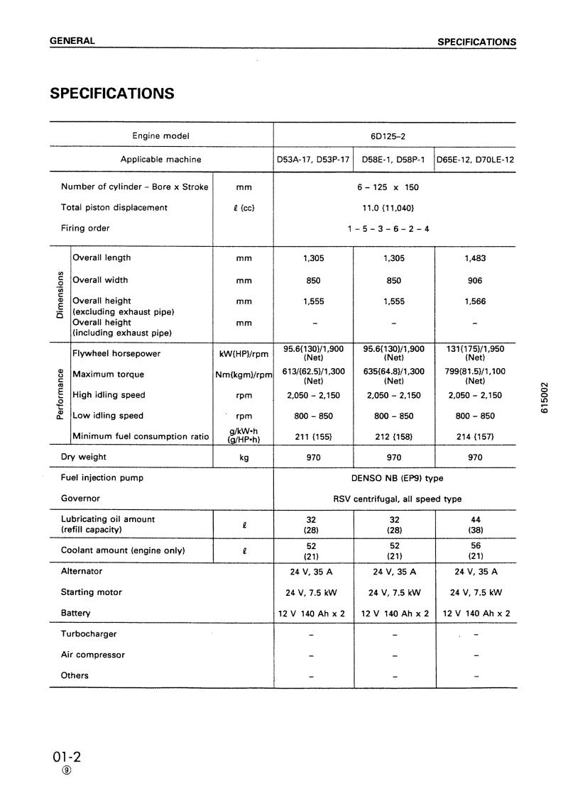
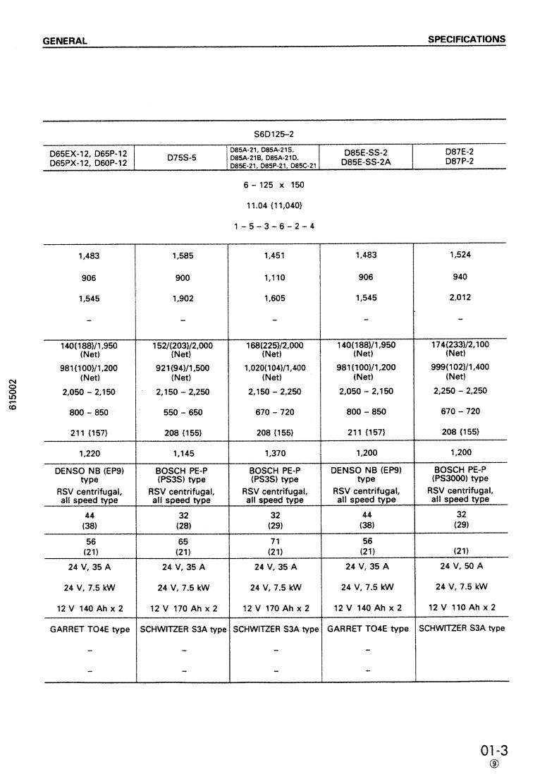
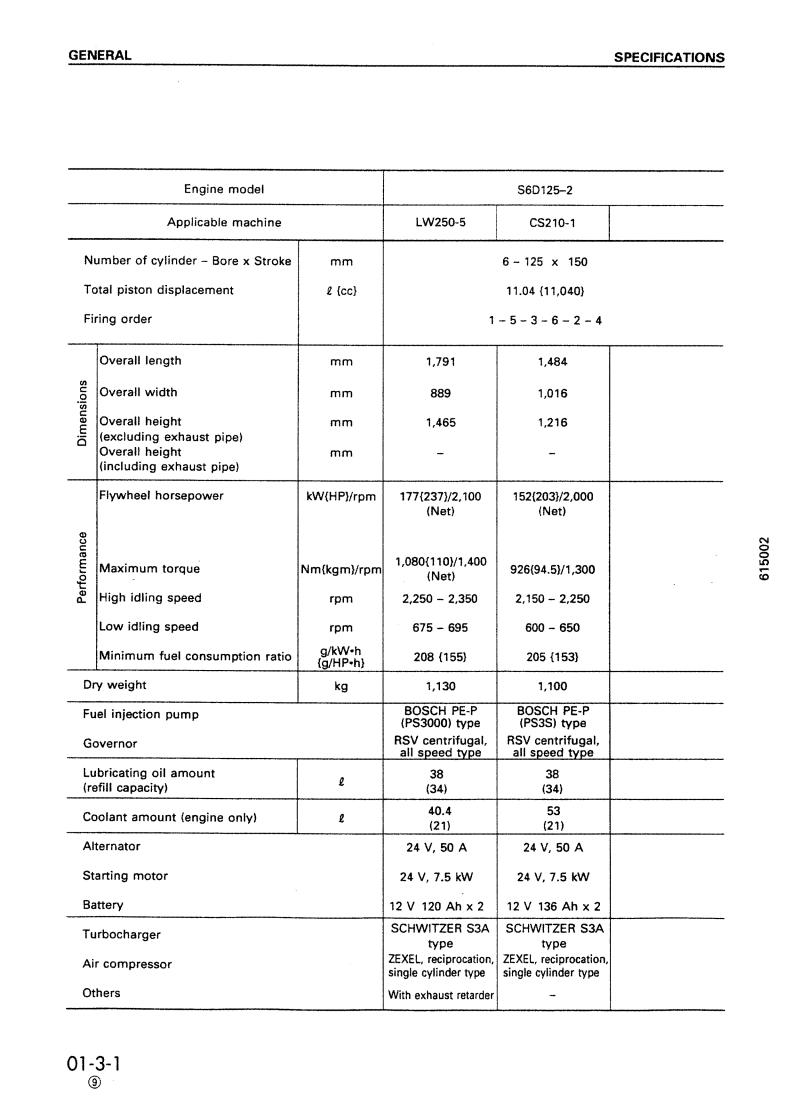
![]()


![]()


 Loading…
ЗАВОДСКАЯ ИНСТРУКЦИЯ ДВС S6D125-1

Для скачивания нажмите на кнопку перевести
После нажатия кнопки “перевести” Вы будете перенаправлены на платежный сервис ЮКassa для выбора способа оплаты.
После осуществления платежа нажмите на ссылку “вернуться на сайт” после этого начнется скачивание файла. Пожалуйста при оплате указывайте реальный свой mail что бы при возникновении какой либо ситуации мы могли быстрее вам помочь. Если у вас возникли вопросы обращайтесь ak.zxzxzx@ro.ru
- CATERPILLAR CAT 320-345
- KOMATSU PC 200-300-400 7-8
- РЕМОНТ HITACHI 330-370MTH
- РЕМОНТ БУЛЬДОЗЕРА KOMATSU D-275A-5
- Ремонт бульдозера komatsu D65
- Ремонт бульдозера komatsu D65Е-12
- Руководство по работе с монитором экскаватора PC200-8
Поиск товаров
Группа компании “RICHTONE” всегда готова предложить Вам запасные части для техники Komatsu в нашем каталоге.
Для того что бы СКАЧАТЬ данную инструкцию напишите нам на электронную почту rceshopmanuals@gmail.com
подождите загрузки книги
Часть 1
|
Производитель |
||||||||||||||||||||||||||||||||||||||||||||||||||||||||||||||||||||||||||||||||||||||||||||||||||||||||||||||||||||||||||||||||||||||||||||||||||||||||||||||||||||||||||||||||||||||||||||||||||||||||||||||||||||||||||||||||||||||||||||||||||||||||||||||||||||||||||||||||||||||||||||||||||||||||||||||||||||||||||||||||||||||||||||||||||||||||||||||||||||||||||||||||||||||||||||||||||||||||||||||||||||||||||||||||||||||||||||||||||||||||||||||||||||||||||||||||||||||||||||||||||||||||||||||||||||||||||||||||||||||||||||||||||||||||||||||||||||||||||||||||||||||||||||||||||||||||||||||||||||||||||||||||||||||||||||||||||||||||||||||||||||||||||||||||||||||||||||||||||||||||||||
|


-
Page 1
SEBM023407 © 2004 All Rights Reserved 00-1 Printed in Japan 05-04(02) -
Page 2: Table Of Contents
CONTENTS No. of page GENERAL ……………………… 01-1 STRUCTURE AND FUNCTION ……………. 11-1 TESTING AND ADJUSTING …………….12-1 DISASSEMBLY AND ASSEMBLY …………..13-1 MAINTENANCE STANDARD …………….14-1 REPAIR AND REPLACEMENT OF PARTS ……..15-1 00-2 170-3 SERIES…
-
Page 3
12-5-1 12-228 01-7 11-27 12-6 12-112-2 12-229 01-8 11-28 12-6-1 12-113 12-230 01-9 11-29 12-7 12-114 12-231 01-10 11-30 12-8 12-114-1 12-232 01-11 11-31 12-9 12-115 12-233 01-12 11-32 12-10 12-116 12-234 01-13 11-33 12-11 12-117 12-235 00-2-1 170-3 SERIES… -
Page 4
12-367 12-316 13-50 Q 15-15 12-317 13-51 Q 15-16 13-1 12-318 13-52 Q 15-17 13-2 12-319 13-53 Q 15-18 13-3 12-320 13-54 Q 15-19 13-4 12-321 13-55 Q 15-20 13-5 12-322 13-56 Q 15-21 13-6 12-323 13-57 00-2-2 170-3 SERIES… -
Page 5
Proper service and repair is extremely important for safe machine operation. The service and repair techniques recommended by Komatsu and described in this manual are both effective and safe. Some of these techniques require the use of tools specially designed by Komatsu for the specific purpose. -
Page 6
SAFETY SAFETY NOTICE PRECAUTIONS DURING WORK 19.Be sure to assemble all parts again in their origi- nal places. 11. When removing the oil filler cap, drain plug or Replace any damaged parts with new parts. hydraulic pressure measuring plugs, loosen •… -
Page 7: General
FOREWORD GENERAL FOREWORD GENERAL This shop manual has been prepared as an aid to improve the quality of repairs by giving the serviceman an accurate understanding of the product and by showing him the correct way to perform repairs and make judge- ments.
-
Page 8
DISTRIBUTION AND UPDATING Any additions, amendments or other changes will be Symbol Item Remarks sent to KOMATSU distributors. Get the most up-to- date information before you start any work. Special safety precautions ¤ Safety are necessary when per- forming the work. -
Page 9
FOREWORD HOISTING INSTRUCTIONS HOISTING INSTRUCTIONS HOISTING Slinging near the edge of the hook may cause ¤ the rope to slip off the hook during hoisting, and H eavy parts (25 kg or more) must be lifted a serious accident can result. Hooks have max- with a hoist, etc. -
Page 10
FOREWORD METHOD OF DISASSEMBLING, CONNECTING PUSH-PULL TYPE COUPLER METHOD OF DISASSEMBLING, CONNECTING PUSH-PULL TYPE COUPLER ¤ B efore carrying out the following work, release Type 1 the residual pressure from the hydraulic tank. For details, see TESTING AND ADJUSTING, Releasing residual pressure from hydraulic tank. -
Page 11
FOREWORD METHOD OF DISASSEMBLING, CONNECTING PUSH-PULL TYPE COUPLER Type 2 Type 3 1) Hold the mouthpiece of the tightening portion 1) Hold the mouthpiece of the tightening portion and push body (2) in straight until sliding pre- and push body (2) in straight until sliding pre- vention ring (1) contacts contact surface a of vention ring (1) contacts contact surface a of the hexagonal portion at the male end. -
Page 12
# The recommended coating materials such as adhesives, gasket sealants and greases used for disassembly and assembly are listed below. # For coating materials not listed below, use the equivalent of products shown in this list. Category Komatsu code Part No. Q’ty Container Main applications, featuresr •… -
Page 13
FOREWORD COATING MATERIALS Category Komatsu code Part No. Q’ty Container Main applications, featuresr • Ftures: Silicon based, quick hard- ening type LG-7 790-129-9070 Tube • Used as sealant for flywheel housing, intake manifold, oil an, Adhesives thermostat housing, etc. •… -
Page 14
FOREWORD STANDARD TIGHTENING TORQUE STANDARD TIGHTENING TORQUE STANDARD TIGHTENING TORQUE TABLE (WHEN USING TORQUE WRENCH) # In the case of metric nuts and bolts for which there is no special instruction, tighten to the torque given in the table below. Thread diameter Width across of bolt… -
Page 15
FOREWORD STANDARD TIGHTENING TORQUE TABLE OF TIGHTENING TORQUES FOR SPLIT FLANGE BOLTS # In the case of split flange bolts for which there is no special instruction, tighten to the torque given in the table below. Thread diameter Width across flat Tightening torque 65.7 11.5… -
Page 16
FOREWORD STANDARD TIGHTENING TORQUE TIGHTENING TORQUE FOR 102 ENGINE SERIES 1) BOLT AND NUTS Use these torques for bolts and nuts (unit: mm) of Cummins Engine. Thread diameter Tightening torque 1.02 0.20 2.45 0.41 4.38 0.61 7.85 1.22 2) EYE JOINTS Use these torques for eye joints (unit: mm) of Cummins Engine. -
Page 17
FOREWORD ELECTRIC WIRE CODE ELECTRIC WIRE CODE In the wiring diagrams, various colors and symbols are employed to indicate the thickness of wires. This wire code table will help you understand WIRING DIAGRAMS. Example: 5WB indicates a cable having a nominal number 5 and white coating with black stripe. CLASSIFICATION BY THICKNESS Copper wire Current… -
Page 18
FOREWORD CONVERSION TABLE CONVERSION TABLE METHOD OF USING THE CONVERSION TABLE The Conversion Table in this section is provided to enable simple conversion of figures. For details of the method of using the Conversion Table, see the example given below. EXAMPLE •… -
Page 19
FOREWORD CONVERSION TABLE Millimeters to Inches 1 mm = 0.03937 in 0.039 0.079 0.118 0.157 0.197 0.236 0.276 0.315 0.354 0.394 0.433 0.472 0.512 0.551 0.591 0.630 0.669 0.709 0.748 0.787 0.827 0.866 0.906 0.945 0.984 1.024 1.063 1.102 1.142 1.181 1.220 1.260… -
Page 20
FOREWORD CONVERSION TABLE Liter to U.S. Gallon 1 l = 0.2642 U.S. Gal 0.264 0.528 0.793 1.057 1.321 1.585 1.849 2.113 2.378 2.642 2.906 3.170 3.434 3.698 3.963 4.227 4.491 4.755 5.019 5.283 5.548 5.812 6.076 6.340 6.604 6.869 7.133 7.397 7.661 7.925… -
Page 21
FOREWORD CONVERSION TABLE kgm to ft. lb 1 kgm = 7.233 ft. lb 14.5 21.7 28.9 36.2 43.4 50.6 57.9 65.1 72.3 79.6 86.8 94.0 101.3 108.5 115.7 123.0 130.2 137.4 144.7 151.9 159.1 166.4 173.6 180.8 188.1 195.3 202.5 209.8 217.0 224.2… -
Page 22
FOREWORD CONVERSION TABLE kg/cm to lb/in 1kg/cm = 14.2233 lb/in 14.2 28.4 42.7 56.9 71.1 85.3 99.6 113.8 128.0 142.2 156.5 170.7 184.9 199.1 213.4 227.6 241.8 256.0 270.2 384.0 398.3 412.5 284.5 298.7 312.9 327.1 341.4 355.6 369.8 426.7 440.9 455.1 469.4… -
Page 23
FOREWORD CONVERSION TABLE Temperature Fahrenheit-Centigrade Conversion ; a simple way to convert a Fahrenheit temperature reading into a Cen- tigrade temperature reading or vice versa is to enter the accompanying table in the center or boldface col- umn of figures. These figures refer to the temperature in either Fahrenheit or Centigrade degrees. -
Page 24
FOREWORD UNITS UNITS In this manual, the measuring units are indicated with Internatinal System of units (SI). As for reference, conventionally used Gravitational System of units are indicated in parentheses { Example: N {kg} Nm {kgm} MPa {kg/cm kPa {mmH kPa {mmHg} kW/rpm {HP/rpm} g/kWh {g/HPh}… -
Page 26
APPLICABLE MACHINE GENERAL APPPLICABLE MACHINE Engine Engine Serial No. Applicable machine SA6D170E-3 D375A-5 Bulldozer PC1250-7 Hydraulic excavator WA600-3 Wheel loader WD600-3 Wheel dozer SAA6D170E-3 HD465-7 Dump truck HD605-7 Dump truck Generator Generator 01-2 170-3 SERIES ➅… -
Page 29
218 {160} 211 {155} 212 {158} (60Hz) 2,900 2,870 2,740 2,565 Trochoid gear pump (KOMATSU HPI system) Electronic control type 64 (60) 67 (56) 67 (56) 196 (190) 137 (Engine side: 47) 137 (Engine side: 47) 137 (Engine side: 47) —… -
Page 35
GENERAL OVERALL DRAWING SAA6D170E-3 VIEW FROM RIGHT SIDE The illustration shows the engine for the WA600-3. The actual engine may be different because of modifications. a. Center of crankshaft b. Rear face of flywheel housing 01-7 170-3 SERIES… -
Page 36
GENERAL OVERALL DRAWING SAA6D170E-3 VIEW FROM FRONT The illustration shows the engine for the WA600-3. The actual engine may be different because of modifications. a. Center of crankshaft b. Center of cylinder liner 01-8 170-3 SERIES… -
Page 37
GENERAL OVERALL DRAWING SAA6D170E-3 VIEW FROM REAR The illustration shows the engine for the WA600-3. The actual engine may be different because of modifications. a. Center of crankshaft b. Center of cylinder liner 01-9 170-3 SERIES… -
Page 38
GENERAL OVERALL DRAWING SAA6D170E-3 VIEW FROM TOP The illustration shows the engine for the WA600-3. The actual engine may be different because of modifications. a. Center of cylinder liner 01-10 170-3 SERIES… -
Page 39
GENERAL OVERALL DRAWING SAA6D170E-3 VIEW FROM LEFT SIDE The illustration shows the engine for the normal generator. The actual engine may be different because of modifications. a. Center of crankshaft b. Rear face of flywheel housing 01-11 170-3 SERIES… -
Page 40
GENERAL OVERALL DRAWING SAA6D170E-3 VIEW FROM RIGHT SIDE The illustration shows the engine for the normal generator. The actual engine may be different because of modifications. a. Center of crankshaft b. Rear face of flywheel housing 01-12 170-3 SERIES… -
Page 41
GENERAL OVERALL DRAWING SAA6D170E-3 VIEW FROM FRONT The illustration shows the engine for the normal generator. The actual engine may be different because of modifications. a. Center of crankshaft b. Center of cylinder liner 01-13 170-3 SERIES… -
Page 42
GENERAL OVERALL DRAWING SAA6D170E-3 VIEW FROM REAR The illustration shows the engine for the normal generator. The actual engine may be different because of modifications. a. Center of crankshaft b. Center of cylinder liner 01-14 170-3 SERIES… -
Page 43
GENERAL OVERALL DRAWING SAA6D170E-3 VIEW FROM TOP The illustration shows the engine for the normal generator. The actual engine may be different because of modifications. a. Center of cylinder liner 01-15 170-3 SERIES… -
Page 45
ENGINE PERFORMANCE CURVE ENGINE PERFORMANCE CURVE Engine Engine serial No. Applicable machine Page SA6D170E-3 D375A-5 01 – 18 WA600-3 01 – 19 WD600-3 01 – 22 SAA6D170E-3 PC1250-7 01 – 20 HD465-7 01 – 21 HD605-7 01-17 170-3 SERIES ➅… -
Page 47
GENERAL ENGINE PERFORMANCE CURVE SAA6D170E-3 (WA600-3) Flywheel horsepower: 337 kW {452 HP} /2,000 rpm (Net) Maximum torque : 2,120 Nm {216 kgm} /1,400 rpm (Net) 01-19 170-3 SERIES… -
Page 50
GENERAL ENGINE PERFORMANCE CURVE SAA6D170E-3 (WD600-3) Flywheel horsepower: 370 kW {497 HP} /2,000 rpm (Net) Maximum torque : 2,391 Nm {244 kgm} /1,400 rpm (Net) 01-22 170-3 SERIES ➅… -
Page 53
1. Inner element 2. Outer element 3. Check valve 4. Tube (34 pcs.) 5. Precleaner 6. Body of air cleaner A. Air inlet B. To turbocharger (sucked air) C. To muffler (dust) 11-3 170-3 SERIES ➅… -
Page 54
KTR110L (oil cooled type) 1. Blower housing A. Air intake SPECIFICATIONS 2. Center housing B. Air output Type: Komatsu KTR110L 3. Thrust nozzle C. Exhaust (inlet port) (oil cooled type) 4. Turbine housing D. Exhaust (outlet port) Overall length: 308 mm 5. -
Page 55
• Engine oil is supplied from hole E at the top of center housing, lubricates the bearings and the lubricating portion, then returns to the engine oil pan from the hole F at the bottom of the center housing. 11-5 170-3 SERIES… -
Page 56
KTR110L (water cooled type) 1. Blower housing 11. Seal ring SPECIFICATIONS 2. V-band 12. Blower impeller Type: Komatsu KTR110L 3. Defuser plate (water cooled type) 4. Center housing A. Intake inlet Overall length: 308 mm (water-cooled center housing is option) B. -
Page 57
AFTERCOOLER STRUCTURE AND FUNCTION AFTERCOOLER AIR-COOLED TYPE The specifications are subject to change according to modification etc. SAA6D170E-3 (WA600-3) A. Intake air port 1. Tank (Turbocharger Intake manifold) 2. Side support 3. Tube 4. Fin 11-7 170-3 SERIES… -
Page 58
AFTERCOOLER STRUCTURE AND FUNCTION AIR-COOLED TYPE The specifications are subject to change according to modification etc. SAA6D170E-3 (Generator) a. Intake air port 1. Tank (Turbocharger Intake manifold) 2. Side support 3. Tube 4. Fin 11-8 170-3 SERIES… -
Page 59
1. Cylinder head a. Fuel inlet (for fuel timing) 2. Rocker arm housing b. Fuel returrn 3. Cylinder head cover C. Fuel inlet (for fuel supply) 4. Valve guide 5. Injector 6. Air vent tube (for cooling water) 11-10 170-3 SERIES… -
Page 60
STRUCTURE AND FUNCTION CYLINDER HEAD SPECIFICATIONS Cylinder head • Direct fuel injection type, 4 valves • Split type (1 cylinder, 1 head) Valve seat insert • Intake valve insert Both press fitted to seat • Exhaust valve insert 11-11 170-3 SERIES… -
Page 61
9. Main metal cap 2. Cylinder block 10. Main metal cap bolt 3. Cylinder liner 11. Front oil seal 4. Crevice seal 12. Piston cooling nozzle 5. Liner O-ring 13. Oil level gauge 6. Liner O-ring 7. Thrust metal 11-12 170-3 SERIES… -
Page 62
Front oil seal • Middle : O-ring (Ethylene propylene rubber) • Single lip with dust seal (Lay-down seal) • Bottom: O-ring (Silicon rubber) Piston cooling • With cooling nozzle (2 for each cylinder, with sub nozzle at rear) 11-13 170-3 SERIES… -
Page 63
13. Connecting rod cap mounting bolt 5. Top ring 14. Connecting rod metal 15. Crankshaft gear (No.of teeth: 36) 6. Second ring 16. Vibration damper 7. Oil ring 8. Camshaft drive gear (No. of teeth: 63) 17. Crankshaft pulley 9. Main metal 11-14 170-3 SERIES… -
Page 64
(2 nozzles per cylinder) Piston ring TOP ring Engine 2nd ring Oil ring (with inner cut) SA6D170E-3 Barrel face, inner cut, Inner cut, taper face, Bevel cutter, surface SAA6D170E-3 hard chrome plating hard chrome plating nitriding 11-15 170-3 SERIES… -
Page 65
The specifications may be different from the following figure, depending on the type of machine. 1. Rear seal 2. Ring gear (No. of teeth: 118) 3. Flywheel 4. Flywheel housing 5. Engine rotating sensor 6. Barring device (service tool) 11-16 170-3 SERIES… -
Page 66
1. Crankshaft pulley 2. Pin (crankshaft – crankshaft pulley) 3. Pin (crankshaft – vibration damper) 4. Vibration damper 5. Pointer 6. Bolt (crankshaft – vibration damper) 7. Bolt (crankshaft – crankshaft pulley) 11-17 170-3 SERIES… -
Page 67
2. Water pump drive gear (No. of teeth: 31) 3. Idler gear (No. of teeth: 84) 4. Crankshaft gear (No. of teeth: 55) 5. Idler gear (No. of teeth: 67) 6. Alternator, fuel pump drive gear (No. of teeth: 55) 11-18 170-3 SERIES… -
Page 68
2. Idler gear (No. of teeth: 72) 3. Idler gear (No. of teeth: 40) 4. Camshaft gear (No. of teeth: 70) A. Timing mark (between crankshaft gear and idler gear) B. Timing mark (between idler gear and camshaft gear) 11-19 170-3 SERIES… -
Page 69
23. Cam follower shaft 14. Adjustment screw 7. Camshaft gear 24. Oil seal 15. Locknut (No. of teeth: 70) 16. Push rod (for intake) (for intake and exhaust) 8. Lower spring seat UI is the affreviation for Unit Injector. 11-20 170-3 SERIES… -
Page 71
16. Oil pressure gauge 3. Oil pump 10. Crankshaft 4. Regulator valve 11. Camshaft 17. Turbocharger 5. Oil cooler 12. Rocker arm 13. Piston cooling nozzle W. Cooling water 6. Thermo valve 7. Oil filter 14. Timing gear (rear side) 11-22 170-3 SERIES… -
Page 72
3. Oil pump body • Rotating speed: Engine speed x 1.45 4. Drive shaft 5. Bushing 6. Pump cover 7. Oil pump drive gear (No. of teeth: 38) 8. Bushing 9. Driven gear (No. of teeth: 10) 10. Driven shaft 11-24 170-3 SERIES… -
Page 73
OIL PUMP STRUCTURE AND FUNCTION OIL PUMP RELIEF VALVE 1. Valve 2. Spring 11-25 170-3 SERIES… -
Page 74
. Actuating pressure (differential pressure): 4. Oil pressure switch (for filter clogging) 245 ± 19.6 kPa {2.5 ± 0.2 kg/cm 5. Safety valve cap 6. Valve spring 7. Safety valve a. From oil pump b. To all parts of engine 11-26 170-3 SERIES… -
Page 75
• Oil cooler: 2 units installed d. Water inlet • Heat exchange: Min. 60,000 kcal/h • Oil flow: 280 /min • Water flow: 890 /min • No. of stages of cooler element: 9 • Heat transfer area : 0.65 m 11-27 170-3 SERIES… -
Page 76
FUEL SYSTEM DIAGRAM STRUCTURE AND FUNCTION FUEL SYSTEM DIAGRAM HPI is the abbreviation for High-Pressure HPI SYSTEM Injection. 11-28 170-3 SERIES… -
Page 77
5F. Plunger adjusting the opening angle of fuel pump actuator (3D). 5G. Gravity check valve 6. Fuel cooler 7. ECM controller 8. Engine speed sensor 9. Atmospheric pressure sensor 10. Boost pressure sensor 11. Boost temperature sensor 11-29 170-3 SERIES… -
Page 78
ENGINE CONTROLLER CONTROL SYSTEM STRUCTURE AND FUNCTION ENGINE CONTROLLER CONTROL SYSTEM FUNCTION 11-30 170-3 SERIES… -
Page 79
It receives the output signal from the controller. controller and controls the opening (operation) There is one engine speed sensor. It holds the or shutting off (stop) of the fuel supply circuit signal circuit for two systems. from the fuel pump. 11-31 170-3 SERIES… -
Page 80
The devices installed to the machine differ according to the machine mounting the engine, so see the Operation and Mainte- nance Manual for the machine model. 11-32 170-3 SERIES… -
Page 81
12. Discharge check valve 4. Relief valve 13. Pressure sensor 5. Regulator housing 14. Actuator 6. Screen (36 micron) 15. Screen (105 micron) 7. Regulator valve 16. ECM controller 8. Bypass valve 9. Control orifice A. To injector 11-33 170-3 SERIES… -
Page 82
2. Fuel pipe (from pump to ECVA) 8. Fuel pipe (for fuel timing) 3. Fuel pipe (from filter to pump) 9. Fuel pipe (for fuel rail) 4. Fuel filter 10. Fuel pipe (return) 5. Fuel inlet 11. ECVA (ECM controller) 6. Fuel timing 11-34 170-3 SERIES… -
Page 83
FUEL PUMP STRUCTURE AND FUNCTION a. To fuel filter SPECIFICATIONS b. To fuel pump Type : HPI method c. To fuel inlet Lubricating method : Lubrication by fuel 11-35 170-3 SERIES… -
Page 84
9. Gasket 2. Bearing 10. Regulator valve housing 3. Mechanical fuel seal 11. Mounting bolt 4. Gear (outer) 5. Gear (inner) a. Breather (for fuel, oil drain) 6. Check valve (for adjusting fuel pressure) 7. Drive shaft 11-36 170-3 SERIES… -
Page 85
STRUCTURE AND FUNCTION FUEL PUMP FUEL PUMP DRIVE 1. Drive gear (No. of teeth: 55) 2. Coupling 3. Fuel pump 4. Fuel pump drive shaft 5. Bearing housing 11-37 170-3 SERIES… -
Page 86
7. O-ring 20. Bias spring 8. Pin 21. Ring valve (for spill pressure control) 9. Spring housing 22. Screen (for timing) 10. O-ring 23. Timing orifice 11. Lower plunger 24. Oil seal 12. Check ball 25. Return spring 11-38 170-3 SERIES… -
Page 87
A. To timing chamber B. To metering chamber C. Return (to fuel cooler) Fuel injection stroke Start of metering Completion of timing chamber metering Completion of injection metering Start of injection Completion of injection Completion of timing chamber spill 11-39 170-3 SERIES… -
Page 88
Core type: CF40, (4.5/2P) Heat dissipation surface: 6.45 m a. From injector Heat dissipation amount: 11.63 kW {10,000 kcal}/h b. To fuel tank Fuel pressure: Max. 5.88 kPa {0.06 kg/cm (When fuel temperature at cooler inlet ° port is 100 11-40 170-3 SERIES… -
Page 89
FUEL FILTER STRUCTURE AND FUNCTION FUEL FILTER 1. Filter bracket SPECIFICATIONS 2. Filter element Filtering area: 1 m Cartridge 3. Filter case 4. Drain plug a. From fuel tank b. To fuel pump 11-41 170-3 SERIES… -
Page 90
9. Fan 2. Oil cooler 10. Air compressor 3. Corrosion resistor 4. Cylinder liner A. From oil pump (oil) 5. Cylinder block B. To all parts of engine (oil) 6. Water manifold (inside cylinder block) 7. Thermostat 11-43 170-3 SERIES… -
Page 91
/min (at 3,730 rpm) 4. Water seal 5. Oil seal 6. Pump shaft 7. Water pump drive gear (No. of teeth: 31) 8. Inlet housing a. From radiator b. To oil cooler c. From thermostat d. Breather (for water drain) 11-44 170-3 SERIES… -
Page 95
2. Fan belt Direction 3. Tension pulley Crankshaft Tension Model of wind pulley pulley pulley 4. Adjustment bolt from fan 5. Tension pulley bracket 6. Fan pulley WA600-3 Blows out 7. Fan WD600-3 a. Direction of wind 11-48 170-3 SERIES ➅… -
Page 96
1. Tension shaft 7. Ball bearing 2. Spring 8. Oil seal 3. Roller bearing 9. Grease nipple 4. Tension bracket 10. Grease nipple 5. Spacer 11. Adjustment bolt 6. Tension pulley (outside diameter: 150 mm) 11-49 170-3 SERIES ➅… -
Page 98
1. Drive pulley (pulley outside diameter: 182 mm) 2. Alternator pulley (pulley outside diameter: 85 mm) 3. Alternator 4. Alternator mounting bolt 5. Adjustment bolt 6. Locknut 7. V-belt 11-51 170-3 SERIES… -
Page 99
2. Alternator pulley 6B. Primary energized resistance 3. Terminal B 6C. Regulator 4. Terminal R 5. Terminal E Pulley diameter Weight Engine Machine model Type Specification (mm) (kg) D375A-5 SA6D170E-3 Sawafuji Denki, open type 24V, 60A (If equipped) 11-52 170-3 SERIES… -
Page 100
5. Terminal R Unit: mm Pulley diameter Weight Engine Machine model Type Specification (mm) (kg) D375A-5 SA6D170E-3 Sawafuji Denki, open type 24V, 75A 12.5 (If equipped) WA600-3 SAA6D170E-3 Sawafuji Denki, open type 24V, 75A 12.5 WD600-3 11-53 170-3 SERIES ➅… -
Page 101
5. Terminal E Weight Machine Pulley diameter Engine Type Specification model (mm) (kg) Nikko Denki PC1250-7 24V, 50A Open type (brushless) Nikko Denki SAA6D170E-3 HD465-7 24V, 50A Open type (brushless) Nikko Denki HD605-7 24V, 50A Open type (brushless) 11-53-1 170-3 SERIES… -
Page 102
Weight Machine Specifi- relay Engine Type pinion nector model cation mount- (kg) teeth type ing type 27V, Nikko Denki SA6D170E-3 D375A-5 (water-proof, oil-proof type) 7.5kW WA600-3 27V, WD600-3 Nikko Denki SAA6D170E-3 HD465-7 (water-proof, oil-proof type) 7.5kW HD605-7 11-54 170-3 SERIES… -
Page 107
ELECTRICAL HEATER (SAA6D170E-3) ★ The actual engine may be different because of modifications. SPECIFICATIONS 1. Terminal 2. Body Heater type: Electrical intake air heater 3. Heater coil Rated voltage: 22V (DC) 4. Connection diagram Rated current: 111 A 11-58 170-3 SERIES ➅… -
Page 108: 12 Testing And Adjusting
Testing and adjusting alternator belt tension ….. 12-20 Precautions when operating engine as an individual part …………12-21 Arrangement of control devices and electric circuit diagram for HPI …………12-22 Run-in standard …………12-25 Performance test standards ……..12-26 Troubleshooting…………12-101 12-1 170-3 SERIES…
-
Page 111: Standard Value Table For Troubleshooting
10 – 15 98 N {10 kg} This STANDARD VALUE TABLE does not give the standard values for adjusting the engine output. Do not use the values in this table to change the adjusting the ECVA or injector. 12-3-1 170-3 SERIES…
-
Page 112: Standard Value Table For Electrical Parts
2) Turn starting switch Oil pressure Voltage Between (A) – (B) — 4.75 – 5.25 V Oil pressure 0 kPa sensor 0.5 ± 0.08 V {0 mmHg} Between (C) – (B) 689 kPa 4.5 ± 0.08 V {7.03 mmHg} 12-4 170-3 SERIES…
-
Page 113
2) Turn starting switch Fuel pressure Voltage Between (A) – (B) — 4.75 – 5.25 V Fuel rail pressure 103 kPa sensor 0.5 ± 0.04 V {10.5 kg/cm Between (C) – (B) 1,722 kPa 4.5 ± 0.06 V {17.56 kg/cm 12-5 170-3 SERIES… -
Page 114
If the condition is within the range shown in the table below, 1) Turn starting switch it is normal. OFF. 2) Disconnect connec- Resistance Timing rail tor. TIMG actuator 7 – 9 Ω Between (A) – (C) Between (A), (C) – ground Min. 1 MΩ 12-5-1 170-3 SERIES… -
Page 115: Tools For Testing, Adjusting, And Troubleshooting
Coolant freezing 799-202-9001 Specific gravity: 1,100 – 1,300 temperature Pressure valve function Radiator cap tester 799-202-9001 0 – 0.2 MPa{0 – 2 kg/cm Leakage from cooling system Quality of coolant Water tester 799-202-7002 PH, nitrous acid ion density 12-6 170-3 SERIES…
-
Page 116
Fuel rail pressure sensor 3824774) Timing rail pressure sensor 795-799-5470 Fuel pump actuator Cable (cummins No. Fuel rail actuator 3824775) Timing rail actuator Engine oil pressure sensor 795-799-5480 Boost pressure sensor Cable (cummins No. Fuel pump pressure sensor 3824776) 12-6-1 170-3 SERIES… -
Page 118: Troubleshooting For Injector
Unit:°C points. Cylinder No. 1 No. 2 No. 3 No. 4 No. 5 No. 6 Measured value Compensated value Average value 12-8 170-3 SERIES…
-
Page 120: Adjusting Injector Set Load
1st time : 29.4 – 34.3 Nm {3.0 – 3.5 kgm} 2nd time : Loosen fully 3rd time : 29.4 – 34.3 Nm {3.0 – 3.5 kgm} 4th time : Loosen fully 5th time : 29.4 – 34.3 Nm {3.0 – 3.5 kgm} 12-10 170-3 SERIES…
-
Page 121: Measuring Compression Pressure
Install each adapter assembly with the hole for taking out the injector on the opposite side of the holder. Hold the adapter in position with an injector holder. Mounting bolt: 24.5 – 34.3 Nm {2.5 – 3.5 kgm} 12-11 170-3 SERIES…
-
Page 122: Measuring Blow-By Pressure
ING AND ADJUSTING INJECTOR LIFT. machine. Cylinder head cover mounting bolt: 9.8 ± 1.0 Nm {1.0 ± 0.1 kgm} 3. After completing the measurement, remove the measuring equipment and set to the original con- dition. 12-12 170-3 SERIES…
-
Page 123: Measuring Oil Pressure
Precautions when replacing fuel filter cartridge Always use a genuine Komatsu part for the fuel 2. Install the nipple and hose of pressure test kit filter cartridge.
-
Page 124: Measuring Fuel Circuit Pressure
{11.60 ± 1.41} {Max. –203} condition 1.25 ± 0.14 MPa 1,000 2.42 ± 0.21 {12.70 ± 1.41} 1.34 ± 0.14 MPa 1,100 2.59 ± 0.21 {13.70 ± 1.41} 1.46 ± 0.14 MPa 1,200 2.76 ± 0.21 {14.90 ± 1.41} 12-14 170-3 SERIES…
-
Page 125: Visual Inspection Of Return Fuel
(C) and (B)): Engine Signal Fuel pump outlet port speed voltage pressure (reference) (rpm) (MPa{kg/cm 0.83±0.14 1.78±0.21 {8.45±1.41} 0.93±0.1 1.94±0.21 {9.50±1.41} 1.03±0.14 2.10±0.21 {10.53±1.41} 1.14±0.14 2.26±0.21 {11.60±1.41} 1.25±0.14 1,000 2.42±0.21 {12.70±1.41} 1.34±0.14 1,100 2.59±0.21 {13.70±1.41} 1.46±0.14 1,200 2.76±0.21 {14.90±1.41} 12-15 170-3 SERIES…
-
Page 127: Bleeding Air From Fuel Circuit
(3). amount of variation in the engine speed until Locknut: the air is completely removed, so continue to 33.9 – 47.5 Nm {3.5 – 4.8 kgm} run the engine at low idling until the speed becomes stable. 12-17 170-3 SERIES…
-
Page 128: Replacing And Adjusting Fan Belt
RIGID TYPE 1. Replacing 1) Loosen 3 mounting bolts (2) of tension pulley (1). 2) Loosen locknut (3), then loosen adjustment screw (4). 3) Remove the old belt and replace it with a new belt. 12-18 170-3 SERIES…
-
Page 129
3 mm 2) Hold adjustment screw (4) in position, then tighten locknut (3). 3) Tighten 3 mounting bolts (2) to hold tension pulley (1) in position. Mounting bolt : 58.8 – 73.5 Nm {6.0 – 7.5 kgm} 12-19 170-3 SERIES… -
Page 130: Testing And Adjusting Alternator Belt Tension
4) Tighten 2 mounting bolts of alternator (1) and the lock bolt of the bar. Top mounting bolt : 65 – 85 Nm {6.7 – 8.7 kgm} Bottom mounting bolt : 108 – 132 Nm {11 – 13.5 kgm} 12-20 170-3 SERIES…
-
Page 131: Precautions When Operating Engine As An Individual Part
When installing the engine to the machine, replace the oil seal with the double-lip type shown in the diagram below. Seal Part No.: 6240-21-4250 Install the engine, taking care not to damage For details, see DISASSEMBLY AND ASSEM- BLY. 12-21 170-3 SERIES…
-
Page 132: Arrangement Of Control Devices And Electric Circuit Diagram For Hpi
ARRANGEMENT OF CONTROL DEVICES AND TESTING AND ADJUSTING ELECTRIC CIRCUIT DIAGRAM FOR HPI ARRANGEMENT OF CONTROL DEVICES AND ELECTRIC CIRCUIT DIAGRAM FOR HPI Arrangement of control devices (for troubleshooting) 12-22 170-3 SERIES…
-
Page 133
11. Fuel pump pressure sensor (PMPR) 12. Fuel rail pressure sensor (RPR) 13. Timing rail pressure sensor (TPR) Actuator 14. Fuel pump actuator (FLTP) 15. Fuel shut-off valve (FSO+, FSO–) 16. Fuel rail actuator (RAIL) 17. Timing rail actuator (TIMG) 12-23 170-3 SERIES… -
Page 134
ARRANGEMENT OF CONTROL DEVICES AND TESTING AND ADJUSTING ELECTRIC CIRCUIT DIAGRAM FOR HPI Electric circuit diagram (For troubles shooting) 12-24 170-3 SERIES… -
Page 135: Run-In Standard
Dynamometer 1,080 2,160 3,240 4,310 load {kg} {55} {110} {220} {330} {440} Output {HP} {54} {130} {260} {488} {781} Operating time Engine speed Dynamometer load {kg} Output {HP} Operating time Engine speed Dynamometer load {kg} Output {HP} 12-25 170-3 SERIES…
-
Page 136: Performance Test Standards
The table shows the standard values with an air cleaner installed, muffler installed, alternator under no load, and air compressor open (when installed). The dynamometer load shows the value for an arm length of 716 mm. 12-26 170-3 SERIES…
-
Page 137
90 – 110 — {3.5 – 5.5} Min. 118 — — — 70 – 90 80 – 110 — {Min. 1.2} Use JIS No. 2 diesel oil as the fuel. Use SAE15W-40 or SAE30 as the lubricating oil. 12-27 170-3 SERIES… -
Page 139
Oil pressure caution lamp lights up (drop in oil pressure)…………..12-119 S-13 Oil level rises ……………………..12-120 S-14 Water temperature becomes too high (overheating) …………..12-121 S-15 Abnormal noise is made ……………………. 12-122 S-16 Vibration is excessive ……………………12-123 12-101 170-3 SERIES… -
Page 140: Troubleshooting
Even if the failure is repaired, if the root cause of the failure is not repaired, the same failure will occur again. To prevent this, always investigate why the prob- lem occurred. Then, remove the root cause. 12-102 170-3 SERIES…
-
Page 141
Use the in the Cause column as reference for [Degree of use (Operated for long period)] in the [Questions] section as reference. 12-103 170-3 SERIES… -
Page 142: Method Of Using Troubleshooting Chart
When temperature of injector of each cylinder is measured, there are some cylinders that are low Abnormality in timing rail pressure sensor system is indicated ( 1) Inspect sensor directly (Output voltage) Inspect actuator directly (Resistance and filter for clogging) Remedy 12-104 170-3 SERIES…
-
Page 143
[Worn piston ring, cylinder liner]. Follow this column down to the troubleshooting area and carry out the troubleshooting item marked The Remedy is given as [Clean], so carry out cleaning, and the exhaust gas color should return to normal. 12-105 170-3 SERIES… -
Page 144: Starting Performance Is Poor (Starting Always Takes Time)
When starting switch is turned to HEAT, heater mount does not become warm Is voltage 26 — 30V between alternator terminal B and terminal E with engine at low idling? Inspect sensor directly (Output voltage and resistance) Inspect actuator directly (Resistance and filter for clogging) Remedy 12-106 170-3 SERIES…
-
Page 145
In this case, inspect the other devices for the cause.) [514][E-73]: Abnormality in fuel rail actuator [112] [E-83]: Abnormality in timing rail actuator [318][E-93]: Abnormality in fuel pump actuator 12-106-1 170-3 SERIES… -
Page 146: Engine Does Not Start
When terminal B and terminal C of safety relay are connected, engine starts When terminal of safety switch and terminal B of starting motor are connected, engine starts Remedy 1. Carry out troubleshooting of machine 12-107 170-3 SERIES…
-
Page 147: B) Engine Turns But No Exhaust Smoke Comes Out (Fuel Is Not Being Injected)
When starting switch is turned to START, voltage [24V] is not generated between fuel shut-off valve connector pins Inspect timing rail actuator screen directly Inspect sensor directly (Output voltage and resistance) Inspect actuator directly (Resistance and filter for clogging) Remedy 12-108 170-3 SERIES…
-
Page 148
In this case, inspect the other devices for the cause.) [514][E-73]: Abnormality in fuel rail actuator [112] [E-83]: Abnormality in timing rail actuator [318][E-93]: Abnormality in fuel pump actuator 12-108-1 170-3 SERIES… -
Page 149: C) Exhaust Smoke Comes Out But Engine Does Not Start (Fuel Is Being Injected)
When specific gravity of electrolyte and voltage of battery are measured, one of them is low When starting switch is at HEAT, heater mount does not become warm Inspect sensor directly (Output voltage and resistance) Inspect actuator directly (Resistance and filter for clogging) Inspect fuel rail actuator directly Remedy 12-108-2 170-3 SERIES…
-
Page 150
In this case, inspect the other devices for the cause.) [514][E-73]: Abnormality in fuel rail actuator [112] [E-83]: Abnormality in timing rail actuator [318][E-93]: Abnormality in fuel pump actuator 12-109 170-3 SERIES… -
Page 151: Engine Does Not Pick Up Smoothly (Follow-Up Is Poor)
When temperature of injector of each cylinder is measured, there are some cylinders that are low When intake air pressure (boost pressure) is measured, it is found to be normal Inspect actuator directly (Resistance and filter for clogging) Inspect sensor directly (Output voltage and resistance) Inspect for air leakage Remedy 12-110 170-3 SERIES…
-
Page 152
In this case, inspect the other devices for the cause.) [514][E-73]: Abnormality in fuel rail actuator [112] [E-83]: Abnormality in timing rail actuator [318][E-93]: Abnormality in fuel pump actuator 12-110-1 170-3 SERIES… -
Page 153: Engine Stops During Operations
When temperature of injector of each cylinder is measured, there are some cylinders that are low Engine rotates when pump auxiliary equipment (pump, compressor, etc.) is removed Inspect sensor directly (Output voltage and resistance) Inspect actuator directly (Resistance and filter for clogging) Remedy 12-110-2 170-3 SERIES…
-
Page 154
In this case, inspect the other devices for the cause.) [514][E-73]: Abnormality in fuel rail actuator [112] [E-83]: Abnormality in timing rail actuator [318][E-93]: Abnormality in fuel pump actuator 12-111 170-3 SERIES… -
Page 155: Engine Does Not Rotate Smoothly (Hunting)
When flow of spill fuel is checked visually, it is found to be low Inspect sensor directly (Output voltage and resistance) Inspect actuator directly (Resistance and filter for clogging) Inspect fuel rail actuator screen directly Inspect timing rail actuator screen directly Remedy 12-112 170-3 SERIES…
-
Page 156
«EA mode» or «EB mode». (If it is not displayed, it is not probably the cause of the trou- ble. In this case, inspect the other devices for the cause.) [318][E-93]: Abnormality in fuel pump actuator 12-112-1 170-3 SERIES… -
Page 157: Engine Lacks Output (Or Lacks Power)
When temperature of injector of each cylinder is measured, there are some cylinders that are low Inspect sensor directly (Output voltage and resistance) Inspect actuator directly (Resistance and filter for clogging) Check part No. of controller calibration data Remedy 12-112-2 170-3 SERIES…
-
Page 158
In this case, inspect the other devices for the cause.) [514][E-73]: Abnormality in fuel rail actuator [112] [E-83]: Abnormality in timing rail actuator [318][E-93]: Abnormality in fuel pump actuator 12-113 170-3 SERIES… -
Page 159: Exhaust Smoke Is Black (Incomplete Combustion)
When temperature of injector of each cylinder is measured, there are some cylinders that are low Abnormality in timing rail pressure sensor system is indicated ( 2) Inspect sensor directly (Output voltage) Inspect actuator directly (Resistance and filter for clogging) Remedy 12-114 170-3 SERIES…
-
Page 160
[112] [E-83]: Abnormality in timing rail actuator 2.If an error code of the timing rail pressure sensor system is displayed, carry out the troubleshooting in «EA mode» or «EB mode». 12-114-1 170-3 SERIES… -
Page 163: S-10 Fuel Consumption Is Excessive
When flow of return fuel is checked visually, it is found to be low Inspect sensor directly (Output voltage) 1. If an error code of the fuel rail pressure sensor system or timing rail pressure sensor system is displayed, carry out the troubleshooting in «EA mode» or «EB mode». Remedy 12-117 170-3 SERIES…
-
Page 164: S-11 Oil Is In Cooling Water, Or Water Spurts Back, Or Water Level Goes Down
When hydraulic oil, transmission oil on machine side is drained, water is found Carry out pressure-tightness test of cylinder head Inspect cylinder block, liner directly Inspect cylinder liner directly Carry out pressure-tightness test of oil cooler Inspect water pump directly Remedy 12-118 170-3 SERIES…
-
Page 165: Oil Pressure Caution Lamp Lights Up (Drop In Oil Pressure)
Inspect relief valve, regulator valve directly Inspect oil filter directly When engine oil level sensor is replaced, oil pressure lamp goes out (machines equipped with oil level sensor) When oil pressure is measured, it is found to be normal Remedy 12-119 170-3 SERIES…
-
Page 166: S-13 Oil Level Rises
Inspect cylinder block, liner directly Inspect rear oil seal directly Carry out pressure-tightness test of oil cooler Inspect water pump directly Inspect thermostat directly Inspect fuel pump directly Inspect injector directly Inspect pump auxiliary equipment (pump, compressor) directly Remedy 12-120 170-3 SERIES…
-
Page 167: Water Temperature Becomes Too High (Overheating)
When temperature difference between top and bottom radiator tanks is measured, it is found to be excessive Carry out function test on thermostat (cracking temperature) When water temperature is measured, it is found to be normal Remedy 12-121 170-3 SERIES…
-
Page 168: S-15 Abnormal Noise Is Made
Inspect front gear and rear gear directly Inspect cooling fan, belt directly When temperature of exhaust gas of each cylinder is measured, there are some cylinders that are low Inspect piping of pump auxiliary equipment (pump, compressor, etc.) directly Remedy 12-122 170-3 SERIES…
-
Page 172
This section gives an outline of the troubleshooting procedures for the electrical systems related to the engine proper and the engine controller (for construction equipment). When carrying out troubleshooting of the electrical system with the engine mounted on the machine, use this section and the shop manual for the machine. 12-202 170-3 SERIES… -
Page 173
4) Other maintenance items can be checked externally, so check any item that is consid- ered to be necessary. 5) Check if there is any error code display for the controller. 12-203 170-3 SERIES… -
Page 174
Even if the failure is repaired, if the root cause of the failure is not repaired, the same failure will occur again. To prevent this, always investigate why the prob- lem occurred. Then, remove the root cause. 12-204 170-3 SERIES… -
Page 175
Defective engine controller Replace It has probably been reset, so operate Has error code [111] already been — for a short time and watch for any generated 3 or more times? change in symptoms Defective engine controller Replace 12-205 170-3 SERIES… -
Page 178
Abnormality in fuel rail actuator control Abnormality in fuel rail actuator Abnormality in dual output solenoid A system Abnormality in dual output solenoid B system Abnormality 2 in idling validation switch system Abnormality in fuel rail pressure sensor in range 12-208 170-3 SERIES… -
Page 179
Always connect any disconnected con- nectors before going on the next step and when finishing the troubleshooting operation. 12-209 170-3 SERIES… -
Page 180
Between ECMA (6) and (17) (power source): Abnormality in boost ECMA (35): 0.30 V or less detected 4.75 – 5.25 V pressure sensor system Between ECMA (35) and (17) (signal): low level 0.42 – 0.58 V (engine stopped) 12-210 170-3 SERIES… -
Page 181
• Defective engine controller • No lamps light up • Engine output goes down • Defective boost pressure sensor • Defective wiring harness and connector of boost pressure sensor circuit • Defective engine controller 12-211 170-3 SERIES… -
Page 183
— of intake air temperature sensor circuit • Defective engine controller • Yellow lamp lights up • Defective atmospheric pressure sensor • Defective wiring harness and connector of atmospheric pressure sensor circuit — • Defective engine controller 12-213 170-3 SERIES… -
Page 184
600 rpm Max. 0.04 MPa {0.4 kg/cm — At 1,000 rpm Max. 0.08 MPa {0.8 kg/cm pressure (level 2) At 1,500 rpm Max. 0.13 MPa {1.3 kg/cm At 1,800 rpm Max. 0.16 MPa {1.6 kg/cm At 2,000 rpm Max. 0.18 MPa {1.8 kg/cm 12-214 170-3 SERIES… -
Page 186
• Abnormality has occurred in dual output • Resistance of dual output solenoid A Between solenoid pins: 28 – 32 Ω Abnormality in dual output solenoid A circuit ECMB (1): solenoid A system Circuit open or short circuit detected 12-216 170-3 SERIES… -
Page 187
• Broken injector O-ring • Defective engine controller • Yellow lamp lights up • Defective dual output solenoid A • Defective wiring harness and connector — of dual output solenoid A circuit • Defective engine controller 12-217 170-3 SERIES… -
Page 188
ECMB (13): Idling ON signal • Fuel rail pressure sensor detected abnor- mal pressure Abnormality in fuel rail Judgment value (reference): — pressure sensor in range When starting switch is ON: 0.17 MPa {1.76 kg/cm } or more 12-218 170-3 SERIES… -
Page 189
• Defective fuel rail pressure sensor • Limits maximum injection amount to 270 • Defective wiring harness and connector — of fuel rail pressure sensor circuit • Defective engine controller • Excessive suction resistance of fuel filter 12-219 170-3 SERIES… -
Page 190
Is screen of timing rail actuator clogged with dirt? Clean or Clogged timing rail actuator screen replace Defective timing rail actuator or defec- Replace Is engine oil diluted with fuel? tive engine controller Broken injector O-ring Replace 12-220 170-3 SERIES… -
Page 191
Between ECMA (20) and TIMG (C) Max. 10 Ω Ω Between ECMA (1) and Between ECMA (20) and Min. 1 M Min. 1 M Ω surrounding wiring harnesses Ω surrounding wiring harnesses EA-3 Related electrical circuit diagram 12-221 170-3 SERIES… -
Page 193
Between ECMA (28) and SP2 (B) Max. 10 Ω Ω Between ECMA (27) and Between ECMA (28) and Min. 1 M Min. 1 M surrounding wiring harnesses Ω surrounding wiring harnesses Ω EA-4 Related electrical circuit diagram 12-223 170-3 SERIES… -
Page 194
Ω Table 3 ECMA (female), TPR (female) Resistance value Between ECMA (33) and TPR (C) Max. 10 Ω Between ECMA (33) and Min. 1 M surrounding wiring harnesses Ω EA-5 Related electrical circuit diagram 12-224 170-3 SERIES… -
Page 195
Between ECMA (33) and TPR (C) Max. 10 Ω Ω Between ECMA (18) and Between ECMA (33) and Min. 1 M Min. 1 M surrounding wiring harnesses Ω surrounding wiring harnesses Ω EA-6 Related electrical circuit diagram 12-225 170-3 SERIES… -
Page 196
Ω Table 3 ECMA (female), PMPR (female) Resistance value Between ECMA (32) and PMPR (C) Max. 10 Ω Between ECMA (32) and Min. 1 M surrounding wiring harnesses Ω EA-7 Related electrical circuit diagram 12-226 170-3 SERIES… -
Page 197
Between ECMA (32) and PMPR (C) Max. 10 Ω Ω Between ECMA (18) and Between ECMA (32) and Min. 1 M Min. 1 M surrounding wiring harnesses Ω surrounding wiring harnesses Ω EA-8 Related electrical circuit diagram 12-227 170-3 SERIES… -
Page 198
TROUBLESHOOTING EA-9 EA-9 Error code [121] (Abnormality in engine speed sensor 1 system) Carry out troubleshooting for error code [115]. 12-228 170-3 SERIES… -
Page 199
Ω Table 3 ECMA (female), IMPR (female) Resistance value Between ECMA (35) and IMPR (C) Max. 10 Ω Between ECMA (35) and Min. 1 M Ω surrounding wiring harnesses EA-10 Related electrical circuit diagram 12-229 170-3 SERIES… -
Page 200
Between ECMA (35) and IMPR (C) Max. 10 Ω Ω Between ECMA (17) and Between ECMA (35) and Min. 1 M Min. 1 M surrounding wiring harnesses Ω surrounding wiring harnesses Ω EA-11 Related electrical circuit diagram 12-230 170-3 SERIES… -
Page 201
Between ECMB (26) and TPS (C) Max. 10 Ω Ω Between ECMB (29) and Between ECMB (26) and Min. 1 M Min. 1 M surrounding wiring harnesses Ω surrounding wiring harnesses Ω EA-12 Related electrical circuit diagram 12-231 170-3 SERIES… -
Page 202
Between ECMB (30) and RTPS (B) Max. 10 Between ECMB (16) and RTPS (C) Max. 10 Ω Ω Between ECMB (30) and Between ECMB (16) and Min. 1 M Min. 1 M surrounding wiring harnesses Ω surrounding wiring harnesses Ω 12-232 170-3 SERIES… -
Page 203
TROUBLESHOOTING EA-14, EA-15 EA-14 Related electrical circuit diagram EA-15 Error code [134] (Abnormality in remote throttle sensor system low level) Carry out troubleshooting for error code [133]. 12-233 170-3 SERIES… -
Page 204
Ω Table 3 ECMA (female), OPS (female) Resistance value Between ECMA (24) and OPS (C) Max. 10 Ω Between ECMA (24) and Min. 1 M surrounding wiring harnesses Ω EA-16 Related electrical circuit diagram 12-234 170-3 SERIES… -
Page 205
Between ECMA (24) and OPS (C) Max. 10 Ω Ω Between ECMA (17) and Between ECMA (24) and Min. 1 M Min. 1 M surrounding wiring harnesses Ω surrounding wiring harnesses Ω EA-17 Related electrical circuit diagram 12-235 170-3 SERIES… -
Page 206
When troubleshooting for error cause and codes [135] and [141] is carried Defective engine repair damage out, does any problem occur in electrical system? to engine Defective electrical system for oil Repair or pressure sensorDefective electrical replace 12-236 170-3 SERIES… -
Page 207
Between ECMA (17) and CTS (B) Max. 10 Ω Ω Between ECMA (22) and Between ECMA (17) and surround- Min. 1 M Min. 1 M surrounding wiring harnesses Ω ing wiring harnesses Ω EA-19 Related electrical circuit diagram 12-237 170-3 SERIES… -
Page 208
When troubleshooting for error cause and re- codes [144] and [145] is carried Defective engine pair damage out, does any problem occur in to engine electrical system? Defective electrical system for oil pres- Repair or sure sensor replace 12-238 170-3 SERIES… -
Page 209
Min. 1 M Min. 1 M surrounding wiring harnesses Ω surrounding wiring harnesses Ω EA-22 Related electrical circuit diagram EA-23 Error code [154] (Abnormality in intake air temperature sensor system low level) Carry out troubleshooting for error code [153]. 12-239 170-3 SERIES… -
Page 210
Ω Table 3 ECMA (female), AAPS (female) Resistance value Between ECMA (34) and AAPS (C) Max. 10 Ω Between ECMA (34) and Min. 1 M Ω surrounding wiring harnesses EA-24 Related electrical circuit diagram 12-240 170-3 SERIES… -
Page 211
Between ECMA (34) and AAPS (C) Max. 10 Ω Ω Between ECMA (17) and Between ECMA (34) and Min. 1 M Min. 1 M surrounding wiring harnesses Ω surrounding wiring harnesses Ω EA-25 Related electrical circuit diagram 12-241 170-3 SERIES… -
Page 212
Defective engine repair damage to engine Investigate cause and Can engine speed be read • Turn starting switch ON. Defective engine repair damage correctly? to engine Investigate cause and Defective engine repair damage to engine 12-242 170-3 SERIES… -
Page 213
Max. 10 Between ECMA (18) and FSO- Max. 10 Ω Ω Between ECMA (30) and Between ECMA (18) and Min. 1 M Min. 1 M surrounding wiring harnesses Ω surrounding wiring harnesses Ω EA-27 Related electrical circuit diagram 12-243 170-3 SERIES… -
Page 214
Investigate When troubleshooting for error cause and codes [263] and [264] is carried Defective engine repair damage out, does any problem occur in to engine electrical system? Defective electrical system for fuel Repair or temperature sensor replace 12-244 170-3 SERIES… -
Page 215
Min. 1 M Min. 1 M surrounding wiring harnesses Ω surrounding wiring harnesses Ω EA-30 Related electrical circuit diagram EA-31 Error code [265] (Abnormality in fuel temperature sensor system low level) Carry out troubleshooting for error code [263]. 12-245 170-3 SERIES… -
Page 216
Between ECMA (11) and PUMP (A) Max. 10 Ω Ω Between ECMA (40) and Between ECMA (11) and Min. 1 M Min. 1 M surrounding wiring harnesses Ω surrounding wiring harnesses Ω EA-32 Related electrical circuit diagram 12-246 170-3 SERIES… -
Page 220
Max. 10 Ω Between ECMA (2) and surrounding wiring harnesses Min. 1 M Ω EA-36 Related electrical circuit diagram EA-37 Error code [415] (Abnormal drop in oil pressure (level 2)) Carry out troubleshooting for error code [143]. 12-249 170-3 SERIES… -
Page 221
Ω Ω Table 3 Between ECMA (33) and TPR (C) Resistance value Between ECMA (33) and TPR (C) Max. 10 Ω Between ECMA (33) and Min. 1 M Ω surrounding wiring harnesses 12-250 170-3 SERIES… -
Page 222
TROUBLESHOOTING EA-38 EA-38 Related electrical circuit diagram 12-251 170-3 SERIES… -
Page 223
Between ECMB (13) and IVS (B) Max. 10 Ω Ω Between ECMB (13) and Between ECMB (12) and Min. 1 M Min. 1 M surrounding wiring harnesses surrounding wiring harnesses Ω Ω EA-39 Related electrical circuit diagram 12-252 170-3 SERIES… -
Page 224
Between ECMB (13) and IVS (B) Max. 10 Ω Ω Between ECMB (12) and Between ECMB (13) and Min. 1 M Min. 1 M surrounding wiring harnesses surrounding wiring harnesses Ω Ω EA-40 Related electrical circuit diagram 12-253 170-3 SERIES… -
Page 225
TROUBLESHOOTING EA-41, EA-42 EA-41 Error code [441] (Abnormality in battery voltage low level) Carry out troubleshooting for error code [346]. EA-42 Error code [442] (Abnormality in battery voltage high level) Carry out troubleshooting for error code [346]. 12-254 170-3 SERIES… -
Page 226: Error Code [451] (Abnormality In Fuel Rail Pressure Sensor System High Level)
Ω Table 3 ECMA (female), RPR (female) Resistance value Between ECMA (31) and RPR (C) Max. 10 Ω Between ECMA (31) and Min. 1 M Ω surrounding wiring harnesses EA-43 Related electrical circuit diagram 12-255 170-3 SERIES…
-
Page 227: Error Code [452] (Abnormality In Fuel Rail Pressure Sensor System Low Level)
Between ECMA (18) and RPR (B) Max. 10 Ω Ω Between ECMA (18) and Between ECMA (31) and Min. 1 M Min. 1 M surrounding wiring harnesses Ω surrounding wiring harnesses Ω EA-44 Related electrical circuit diagram 12-256 170-3 SERIES…
-
Page 228: Error Code [455] (Abnormality In Fuel Rail Actuator System Current)
Max. 10 Between ECMA (10) and RAIL Max. 10 Ω Ω Between ECMA (3) and Between ECMA (10) and Min. 1 M Min. 1 M surrounding wiring harnesses Ω surrounding wiring harnesses Ω EA-45 Related electrical circuit diagram 12-257 170-3 SERIES…
-
Page 229: Error Code [467] (Abnormality In Timing Rail Actuator Control)
Clogged fuel rail actuator screen replace Replace Defective fuel rail actuator or defective Is engine oil diluted with fuel? engine controller Broken injector O-ring Replace EA-48 Error code [514] (Abnormality in fuel rail actuator) Carry out troubleshooting for error code [468]. 12-258 170-3 SERIES…
-
Page 230: Error Code [527] (Abnormality In Dual Output Solenoid A System)
(female) (1) and surrounding Short circuit in wiring harness between • Disconnect ECMB and wiring harnesses more than 100 ECMB (female) (1) and solenoid replace solenoid connector. Ω Defective engine controller Replace EA-49 Related electrical circuit diagram 12-259 170-3 SERIES…
-
Page 231: Error Code [529] (Abnormality In Dual Output Solenoid B System)
100 replace ECMB (female) (9) and solenoid solenoid connector. Ω Defective engine controller Replace EA-50 Related electrical circuit diagram EA-51 Error code [551] (Abnormality 2 in idling validation switch system) Carry out troubleshooting for error code [431]. 12-260 170-3 SERIES…
-
Page 232: Error Code [554] (Abnormality In Fuel Rail Pressure Sensor In Range)
Min. 1 M surrounding wiring harnesses surrounding wiring harnesses Ω Ω Table 3 ECMA (female), RPR (female) Resistance value Between ECMA (31) and RPR (C) Max. 10 Ω Between ECMA (33) and Min. 1 M surrounding wiring harnesses Ω 12-261 170-3 SERIES…
-
Page 233
TROUBLESHOOTING EA-52 EA-52 Related electrical circuit diagram 12-262 170-3 SERIES… -
Page 234
This section gives an outline of the troubleshooting procedures for the electrical systems related to the engine proper and the engine controller (for construction equipment). When carrying out troubleshooting of the electrical system with the engine mounted on the machine, use this section and the shop manual for the machine. 12-301 170-3 SERIES… -
Page 235: Points To Remember When Troubleshooting
4) Other maintenance items can be checked externally, so check any item that is consid- ered to be necessary. 5) Check if there is any error code display for the controller. 12-302 170-3 SERIES…
-
Page 236
Even if the failure is repaired, if the root cause of the failure is not repaired, the same failure will occur again. To prevent this, always investigate why the prob- lem occurred. Then, remove the root cause. 12-303 170-3 SERIES… -
Page 237: Method Of Using Troubleshooting Charts
[E-58] Is error code [E-59] displayed? • Turn starting switch ON Replace Defective engine controller Turn starting switch ON. Carry out trou- bleshooting for Abnormality in switch power source error code system [E-59] 12-304 170-3 SERIES…
-
Page 238: Error Code Display And Points To Remember When Troubleshooting
Alphabet: A • b • C • d • E • When re-enacting an abnormality or after comple- tion of repair of an abnormality, keep the starting switch at the ON position and the error codes are deleted from memory. 12-305 170-3 SERIES…
-
Page 239
E-bA Abnormality in P constant adjustment volume system E-bb Abnormality in I constant adjustment volume system E-bC Abnormality in D constant adjustment volume system E-bd Abnormality in fuel temperature sensor system E-bE Abnormal rise in fuel temperature 12-306 170-3 SERIES… -
Page 240
3) Handling connectors: Before carrying out troubleshooting, check that all the connectors related to the error code are properly inserted. Always connect any disconnected connectors before going on the next step and when finishing the trouble- shooting operation. 12-307 170-3 SERIES… -
Page 241: Action Taken By Controller And Condition Of Machine When Error Code Is Displayed
Between CN3-1 (6) and (14) (power source): Abnormality in fuel rail CN3-1 (10): 4.78 V or more detected 4.75 — 5.25 V E-70 pressure sensor system Between CM3-1 (10) and (14) (signal): high level 0.42 — 0.58 V (engine stopped) 12-308 170-3 SERIES…
-
Page 242
• Defective engine controller • Controls injection rate open • Defective fuel rail pressure sensor • Defective wiring harness and connector of fuel rail pressure sensor circuit — • Defective engine controller 12-309 170-3 SERIES… -
Page 243
Between CN3-1 (6) and (14) (power source): Abnormality in fuel pump CN3-1 (9): 0.15 V or less detected 4.75 – 5.25 V E-91 pressure sensor system Between CN3-1 (9) and (14) (signal): low level 0.42 – 0.58 V (engine stopped) 12-310 170-3 SERIES… -
Page 244
— • Defective engine controller • Carries out open control of fuel pump • Defective fuel pump pressure sensor • Defective wiring harness and connector of fuel pump pressure sensor circuit — • Defective engine controller 12-311 170-3 SERIES… -
Page 245
• Abnormality has occurred in droop adjust- • Resistance of droop adjustment volume Abnormality in droop ment volume circuit Between CN3-2 (1) and CN3-1 (14): E-b6 adjustment volume Fully closed: Max. 1.1 kW system Fully open: 1.8 – 2.0 kΩ 12-312 170-3 SERIES… -
Page 246
• Defective boost air pressure sensor • Defective wiring harness and connector — — of boost air pressure sensor circuit • Defective engine controller • Defective panel • Defective wiring harness of droop — — adjustment volume circuit • Defective engine controller 12-313 170-3 SERIES… -
Page 247
CN3-2 (8): system 0.3 V or less or 4.7 V or more detected • Fuel temperature sensor has detected Abnormal rise in fuel temperature higher than set temperature — E-bE Judgment value (reference): 76°C or more temperature 12-314 170-3 SERIES… -
Page 248
• Defective wiring harness and connector — — of fuel temperature sensor circuit • Defective engine controller • Leakage of fuel, clogging • Defective fuel cooler at machine end — — • Defective fuel temperature sensor • Defective engine controller 12-315 170-3 SERIES… -
Page 249: Error Code [E-10] (Abnormality In Power Source Voltage System)
[E-58] Is error code [E-59] displayed? • Turn starting switch ON Replace Defective engine controller Turn starting switch ON. Carry out trou- bleshooting for Abnormality in switch power source error code system [E-59] 12-316 170-3 SERIES…
-
Page 250
Max. 10 Between CN1 (13) and FSO- Max. 10 Ω Ω Between CN1 (1) and surrounding Between ECMA (30) and Min. 1 M Min. 1 M wiring harnesses Ω surrounding wiring harnesses Ω EB-2 Related electrical circuit diagram 12-317 170-3 SERIES… -
Page 251: Error Code [E-1B] (Abnormality In Engine Speed Sensor A System)
(B), and between CN3-1 (fe- short circuit in wiring harness between • Disconnect CN3-1 and SP2. replace male) (16) and surrounding wir- CN3-1 (female) (16) and SP2 (female) ing harnesses as shown in Ta- ble 4? Defective engine controller Replace 12-318 170-3 SERIES…
-
Page 252: Error Code [E-1C] (Abnormality In Engine Speed Sensor B System)
Min. 1 M Min. 1 M surrounding wiring harnesses Ω surrounding wiring harnesses Ω EB-3 Related electrical circuit diagram EB-4 Error code [E-1C] (Abnormality in engine speed sensor B system) Carry out troubleshooting for error code [E-1b]. 12-319 170-3 SERIES…
-
Page 253: Error Code [E-21] (Mistaken Of Connection Of Wiring Harness Connector)
• Disconnect CN3-1 and CN5- (female) (1) and CN3-1 (female) wiring harness between CN5-1 Ω replace (14) less than 10 (female) (1) and CN3-1 (female) (14) Repair or Defective engine controller replace EB-5 Related electrical circuit diagram 12-320 170-3 SERIES…
-
Page 254: Error Code [E-22] (Overrun)
Investigate When troubleshooting for error code cause and re- [E-34] is carried out, does any prob- Defective engine pair damage to lem occur in electrical system? engine Repair or Defective electrical system of coolant replace temperature sensor 12-321 170-3 SERIES…
-
Page 255: Error Code [E-24] (Abnormal Drop In Oil Pressure)
Is another error code displayed at • Turn starting switch ON. same time? Go to trouble- shooting for — error code dis- played Replace Has engine oil pressure dropped? Defective engine controller Investigate cause and Defective engine repair damage 12-322 170-3 SERIES…
-
Page 256: Error Code [E-34] (Abnormality In Coolant Temperature Sensor System)
Between CN3-1 (14) and CLTP (B) Max. 10 Ω Ω Between CN3-2 (9) and Between CN3-1 (14) and Min. 1 M Min. 1 M surrounding wiring harnesses Ω surrounding wiring harnesses Ω EB-9 Related electrical circuit diagram 12-323 170-3 SERIES…
-
Page 257: Error Code [E-56] (Abnormality In Solenoid Power Source 1 System)
Repair or (female) (21) and terminal box wiring harness between CN2 (female) • Disconnect CN2. replace Ω GND less than 10 (21) and terminal box GND Repair or Defective engine controller replace EB-10 Related electrical circuit diagram 12-324 170-3 SERIES…
-
Page 258: Error Code [E-57] (Abnormality In Solenoid Power Source 2 System)
Repair or (female) (21) and terminal box wiring harness between CN2 (female) • Disconnect CN2. replace Ω GND less than 10 (21) and terminal box GND Repair or Defective engine controller replace EB-11 Related electrical circuit diagram 12-325 170-3 SERIES…
-
Page 259: Error Code [E-58] (Abnormality In Backup Power Source System)
Repair or (female) (8)(16) and terminal box wiring harness between CN1 (female) • Disconnect CN1. replace Ω GND less than 10 (8)(16) and terminal box GND Repair or Defective engine controller replace EB-12 Related electrical circuit diagram 12-326 170-3 SERIES…
-
Page 260: Error Code [E-59] (Abnormality In Switch Power Source System)
• Turn starting switch OFF. (female) (16)(17) and terminal wiring harness between CN1 (female) • Disconnect CN1. replace Ω box GND less than 10 (16)(17) and terminal box GND Repair or Defective engine controller replace EB-13 Related electrical circuit diagram 12-327 170-3 SERIES…
-
Page 261: Error Code [E-70] (Abnormality In Fuel Rail Pressure Sensor System High Level)
Ω Table 3 CN3-1 (female), RPR (female) Resistance value Between CN3-1 (10) and RPR (C) Max. 10 Ω Between CN3-1 (10) and Min. 1 M surrounding wiring harnesses Ω EB-14 Related electrical circuit diagram 12-328 170-3 SERIES…
-
Page 262: Error Code [E-71] (Abnormality In Fuel Rail Pressure Sensor System Low Level)
Between CN3-1 (10) and RPR (C) Max. 10 Ω Ω Between CN3-1 (14) and Between CN3-1 (10) and Min. 1 M Min. 1 M surrounding wiring harnesses Ω surrounding wiring harnesses Ω EB-15 Related electrical circuit diagram 12-329 170-3 SERIES…
-
Page 263: Error Code [E-72] (Abnormality In Fuel Rail Pressure Sensor System In Range)
Ω surrounding wiring harnesses Table 3 CN3-1 (female), RPR (female) Resistance value Between CN3-1 (10) and RPR (C) Max. 10 Ω Between CN3-1 (10) and Min. 1 M surrounding wiring harnesses Ω EB-16 Related electrical circuit diagram 12-330 170-3 SERIES…
-
Page 264: Error Code [E-73] (Abnormality In Fuel Rail Actuator)
» Is fuel rail actuator screen clogged with dirt? Clean or Clogged fuel rail actuator screen replace Defective fuel rail actuator or defective Is engine oil diluted with fuel? Replace engine controller Replace Broken injector O-ring 12-331 170-3 SERIES…
-
Page 265: Error Code [E-75] (Abnormality With Electric Current In Fuel Rail Actuator System)
Between CN2 (15) and RAIL (C) Max. 10 Between CN2 (17) and RAIL (C) Max. 10 Ω Ω Between CN2 (15) and surrounding Between CM2 (17) and Min. 1 M Min. 1 M wiring harnesses Ω surrounding wiring harnesses Ω 12-332 170-3 SERIES…
-
Page 266
TROUBLESHOOTING EB-18 EB-18 Related electrical circuit diagram 12-333 170-3 SERIES… -
Page 267: Error Code [E-80] (Abnormality In Timing Rail Pressure Sensor System High Level)
Ω Table 3 CN3-2 (female), TPR (female) Resistance value Between CN3-2 (14) and TPR (C) Max. 10 Ω Between CN3-2 (14) and Min. 1 M surrounding wiring harnesses Ω EB-19 Related electrical circuit diagram 12-334 170-3 SERIES…
-
Page 268: Error Code [E-81] (Abnormality In Timing Rail Pressure Sensor System Low Level)
Between CN3-2 (14) and TPR (C) Max. 10 Ω Ω Between CN3-1 (14) and Between CN3-2 (14) and Min. 1 M Min. 1 M surrounding wiring harnesses Ω surrounding wiring harnesses Ω EB-20 Related electrical circuit diagram 12-335 170-3 SERIES…
-
Page 269: Error Code [E-82] (Abnormality In Timing Rail Pressure Sensor System In Range)
Min. 1 M surrounding wiring harnesses Ω surrounding wiring harnesses Ω Table 3 CN3-2 (female), TPR (female) Resistance value Between CN3-2 (14) and TPR (C) Max. 10 Ω Between CN3-2 (14) and Min. 1 M surrounding wiring harnesses Ω 12-336 170-3 SERIES…
-
Page 270
TROUBLESHOOTING EB-21 EB-21 Related electrical circuit diagram 12-337 170-3 SERIES… -
Page 271: Error Code [E-83] (Abnormality In Timing Rail Actuator)
» Is screen of timing rail actuator clogged with dirt? Clean or Clogged timing rail actuator screen replace Defective timing rail actuator or Is engine oil diluted with fuel? Replace defective engine controller Broken injector O-ring Replace 12-338 170-3 SERIES…
-
Page 272: Error Code [E-85] (Abnormality With Electric Current In Timing Rail Actuator System)
Between CN2 (19) and TIMG (C) Max. 10 Ω Ω Between CN2 (9) and surrounding Between CN2 (19) and surrounding Min. 1 M Min. 1 M wiring harnesses wiring harnesses Ω Ω EB-23 Related electrical circuit diagram 12-339 170-3 SERIES…
-
Page 273: Error Code [E-90] (Abnormality In Fuel Pump Pressure Sensor System High Level)
Ω Table 3 CN3-1 (female), PMPR (female) Resistance value Between CN3-1 (9) and PMPR (C) Max. 10 Ω Between CN3-1 (9) and Min. 1 M surrounding wiring harnesses Ω EB-24 Related electrical circuit diagram 12-340 170-3 SERIES…
-
Page 274: Error Code [E-91] (Abnormality In Fuel Pump Pressure Sensor System Low Level)
Between CN3-1 (9) and PMPR (C) Max. 10 Ω Ω Between CN3-1 (14) and Between CN3-1 (9) and Min. 1 M Min. 1 M surrounding wiring harnesses Ω surrounding wiring harnesses Ω EB-25 Related electrical circuit diagram 12-341 170-3 SERIES…
-
Page 275: Error Code [E-93] (Abnormality In Fuel Pump Actuator)
[E-90] and [E-91] is carried out, does any problem occur in electrical system Repair or Defective electrical system for fuel pump pressure sensor replace Is there problem with internal Replace Defective engine controller parts of injector? Defective injector Replace 12-342 170-3 SERIES…
-
Page 276: Error Code [E-95] (Abnormality With Electric Current In Fuel Pump Actuator System)
Between CN2 (18) and PUMP (B) Max. 10 Ω Ω Between CN2 (8) and surrounding Between CN2 (18) and surrounding Min. 1 M Min. 1 M wiring harnesses Ω wiring harnesses Ω EB-27 Related electrical circuit diagram 12-343 170-3 SERIES…
-
Page 277: Error Code [E-A0]
Is there clogging, looseness, breakage, or leakage from fuel filter, piping? Clogging, looseness, breakage, or Repair or leakage from fuel filter, piping replace » Is there problem with internal Defective engine controller Replace parts of injector? Defective injector Replace 12-344 170-3 SERIES…
-
Page 278: Error Code [E-A1] (Abnormality In Starting Switch On Signal System)
Repair or • Disconnect CN5-2 and (female) (10) and ground more wiring harness between CN5-2 Ω replace terminal box 116. than 100k (female) (10) and terminal box 116 Defective engine controller Replace EB-29 Related electrical circuit diagram 12-345 170-3 SERIES…
-
Page 279: Error Code [E-A2] (Abnormality In Power Source Retention Relay System)
CN1 (female) • Disconnect CN1 and power (female) (12) and ground more replace (12) and power source retention relay Ω source retention relay than 100k (female) (1) Defective engine controller Replace EB-30 Related electrical circuit diagram 12-346 170-3 SERIES…
-
Page 280: Error Code [E-A3] (Abnormality In Emergency Stop Signal Input)
(female) (3), terminal box 109 — Repair or harnesses between CN5-2 (female) (3) surrounding wiring harnesses • Disconnect all connectors. replace Ω and terminal box 109 more than 100 k Replace Defective engine controller EB-31 Related electrical circuit diagram 12-347 170-3 SERIES…
-
Page 281: Error Code [E-B0] (Abnormality In Atmospheric Pressure Sensor System High Level)
Ω Table 3 CN3-1 (female), AAPR (female) Resistance value Between CN3-1 (20) and AAPR (C) Max. 10 Ω Between CN3-1 (20) and Min. 1 M surrounding wiring harnesses Ω EB-32 Related electrical circuit diagram 12-348 170-3 SERIES…
-
Page 282: Error Code [E-B1] (Abnormality In Atmospheric Pressure Sensor System Low Level)
Between CN3-1 (20) and AAPR (C) Max. 10 Ω Ω Between CN3-1 (14) and Between CN3-1 (20) and Min. 1 M Min. 1 M Ω surrounding wiring harnesses Ω surrounding wiring harnesses EB-33 Related electrical circuit diagram 12-349 170-3 SERIES…
-
Page 283: Error Code [E-B2] (Abnormality In Boost Air Pressure Sensor System High Level)
Ω Table 3 CN3-2 (female), IMPR (female) Resistance value Between CN3-2 (13) and IMPR (B) Max. 10 Ω Between CN3-2 (13) and Min. 1 M surrounding wiring harnesses Ω EB-34 Related electrical circuit diagram 12-350 170-3 SERIES…
-
Page 284: Error Code [E-B3] (Abnormality In Boost Air Pressure Sensor System Low Level)
Between CN3-1 (14) and IMPR (B) Max. 10 Ω Ω Between CN3-1 (14) and Between CN3-2 (13) and Min. 1 M Min. 1 M surrounding wiring harnesses surrounding wiring harnesses Ω Ω EB-35 Related electrical circuit diagram 12-351 170-3 SERIES…
-
Page 285: Error Code [E-B4] (Abnormality In Boost Air Pressure Sensor System In Range)
(Except portions of related circuit diagram) Defective engine controller Replace Table 1 CN3-2 (female), CN3-1 (female) Volume Resistance value Fully closed (full left) Max. 1.1 k Ω Between CN3-2 (1) and CN3-1 (14) Depressed (idling OFF) 1.8 – 2.0 k Ω 12-352 170-3 SERIES…
-
Page 286
TROUBLESHOOTING EB-37 EB-37 Related electrical circuit diagram 12-353 170-3 SERIES… -
Page 287: Error Code [E-B7] (Abnormality In Rated Speed Adjustment Volume System)
Defective engine controller Replace Table 1 CN3-2 (female), CN3-1 (female) Volume Resistance value Fully closed (full left) Max. 1.1 k Ω Between CN3-2 (1) and CN3-1 (14) Full open (full right) 1.8 – 2.0 k Ω 12-354 170-3 SERIES…
-
Page 288
TROUBLESHOOTING EB-38 EB-38 Related electrical circuit diagram 12-355 170-3 SERIES… -
Page 289: Error Code [E-B8] (Abnormality In Li Speed Adjustment Volume System)
Replace Defective engine controller Table 1 CN3-2 (female), CN3-1 (female) Volume Resistance value Fully closed (full left) Max. 1.1 k Ω Between CN3-2 (10) and CN3-1 (14) Fully open (full right) 1.8 – 2.0 k Ω 12-356 170-3 SERIES…
-
Page 290
TROUBLESHOOTING EB-39 EB-39 Related electrical circuit diagram 12-357 170-3 SERIES… -
Page 291: Error Code [E-B9] (Abnormality In Lamp Time Adjustment Volume System)
Is resistance between CN3-2 (female) (16) and surrounding • Turn starting switch OFF. wiring harnesses more than 100 Defective panel Replace Ω • Disconnect all connectors. ? (Except portions of related circuit diagram) Defective engine controller Replace 12-358 170-3 SERIES…
-
Page 292
TROUBLESHOOTING EB-40 EB-40 Related electrical circuit diagram 12-359 170-3 SERIES… -
Page 293: Error Code [E-Ba] (Abnormality In P Constant Adjustment Volume System)
Replace Defective engine controller Table 1 CN3-2 (female), CN3-1 (female) Volume Resistance value Fully closed (full left) Max. 1.1 k Ω Between CN3-2 (5) and CN3-1 (14) Fully open (full right) 1.8 – 2.0 k Ω 12-360 170-3 SERIES…
-
Page 294
TROUBLESHOOTING EB-41 EB-41 Related electrical circuit diagram 12-361 170-3 SERIES… -
Page 295: Error Code [E-Bb] (Abnormality I Constant Adjustment Volume System)
(Except portions of related circuit Remedy Defective engine controller Table 1 CN3-2 (female), CN3-1 (female) Volume Resistance value Fully closed (full left) Max. 1.1 k Ω Between CN3-2 (6) and CN3-1 (14) Fully open (full right) 1.8 – 2.0 k Ω 12-362 170-3 SERIES…
-
Page 296
TROUBLESHOOTING EB-42 EB-42 Related electrical circuit diagram 12-363 170-3 SERIES… -
Page 297: Error Code [E-Bc] (Abnormality In D Constant Adjustment Volume System)
Replace Defective engine controller Table 1 CN3-2 (female), CN3-1 (female) Volume Resistance value Fully closed (full left) Max. 1.1 k Ω Between CN3-2 (7) and CN3-1 (14) Fully open (full right) 1.8 – 2.0 k Ω 12-364 170-3 SERIES…
-
Page 298
TROUBLESHOOTING EB-43 EB-43 Related electrical circuit diagram 12-365 170-3 SERIES… -
Page 299: Error Code [E-Bd] (Abnormality In Fuel Temperature Sensor System)
Between CN3-1 (14) and FLTP (B) Max. 10 Ω Ω Between CN3-2 (8) and Between CN3-1 (14) and Min. 1 M Min. 1 M surrounding wiring harnesses Ω surrounding wiring harnesses Ω EB-44 Related electrical circuit diagram 12-366 170-3 SERIES…
-
Page 300: Error Code [E-Be] (Abnormal Rise In Fuel Temperature)
Investigate When troubleshooting for error cause and code [E-bd] is carried out, does Defective engine any problem occur in electrical repair damage system? to engine Repair or Defective electrical system for fuel replace 12-367 170-3 SERIES…
-
Page 301: 13 Disassembly And Assembly
Method of using manual……..13- 2 Precautions when carrying out operation..13- 3 Special tool list ……….13- 5 Disassembly of engine ……..13 -7 Assembly of engine………. 13-23 Washing parts ……….13-53 Measuring parts ……….13-54 13-1 170-3 SERIES…
-
Page 302
3. Listing of special tools For details of the description, part number, and quantity of any tools (A1, etc.) that appear in the opera- tion procedure, see the SPECIAL TOOLS LIST given in this manual. 13-2 170-3 SERIES… -
Page 303
07379-00500 07378-10500 07371-30500 3)If the part is not under hydraulic pressure, the following corks can be used. Dimensions Nominal Part Number number 07049-00608 07049-00811 07049-01012 07049-01215 07049-01418 11.5 07049-01620 13.5 07049-01822 07049-02025 07049-02228 18.5 07049-02430 07049-02734 22.5 13-3 170-3 SERIES… -
Page 304
If the piping or hydraulic equipment have been removed, always bleed the air from the system after reas- sembling the parts. For details, see TESTING AND ADJUSTING, Bleeding air. • Add the specified amount of grease (molybdenum disulphide grease) to the work equipment parts. 13-4 170-3 SERIES… -
Page 305
Piston ring tool of piston ring Pulling out cylinder » 795-102-1301 Liner puller liner » 795-225-1512 Liner driver Press fitting of cylin- » 790-101-5221 Grip der liner » 01010-81250 Bolt Insertion of piston » 795-225-1700 Piston holder assembly 13-5 170-3 SERIES… -
Page 306
79A-212-4201 Socket kit For 12-sided bolt of bolt Measurement of pis- » 795-901-1120 Wear gauge For measuring parts ton ring groove wear Press fitting of valve » 795-611-1170 Screwdriver stem seal » Cranking engine 6162-23-4500 Barring device 13-6 170-3 SERIES… -
Page 307
The position for connecting the wiring dif- fer s according to the machine it is mounted on. 3. Starting motor assembly Remove starting motor assembly (2). The number of starting motors differs accord- ing to the machine they are mounted on. 13-7 170-3 SERIES… -
Page 308
3) Move bypass tube (14) up, and disconnect portion connecting water pump. 5. Exhaust manifold assembly 1) Lift off exhaust manifold assembly (10). Exhaust manifold assembly: 40 kg 4) Remove thermostat housing (15). 2) Remove air bleed tube (11). 13-8 170-3 SERIES… -
Page 309
2) Remove water pump assembly (18). iv) Remove plug (24) from cooler body (25). 8. Oil cooler assembly 1) Remove 2 oil cooler assemblies (19). 2) Disassemble oil cooler assembly as follows. Remove cooler core (20). ii) Remove cover (21). 13-9 170-3 SERIES… -
Page 310
2) Remove bracket (38). 1) Remove fuel tube (30). 2) Remove fuel filter assembly (31). 11. Intake manifold assembly 1) Remove fuel inlet tube (32). 2) Remove timing rail tube (33). 3) Remove fuel rail tube (34). 13-10 170-3 SERIES… -
Page 311
The shape of the dipstick differs accord- ing to the machine it is mounted on. 2) Remove oil filler tube (44). The shape of the oil filler tube differs according to the machine it is mounted 3) Remove oil pressure sensor (45). 13-11 170-3 SERIES… -
Page 312
3) Disassemble rocker arm assembly as fol- lows. Remove exhaust valve arm assembly (52), injector arm assembly (53), and intake valve arm assembly (54) from shaft (55). 16. Cylinder head cover Remove 6 cylinder head covers (50). 13-12 170-3 SERIES… -
Page 313
1) Remove holder mounting bolts. 2) Using tool A, remove 6 injector assemblies (60). Fit the pin at the tip of the tool into the fuel hole in the injector, then move the weight up and down to pull it out. 13-13 170-3 SERIES… -
Page 314
8 valve cotters (65). 24. Cam follower cover Remove 6 cam follower covers (71). The position of the breather differs according to the machine it is mounted on. ii) Remove 4 spring seats (66). iii) Remove 4 valve springs (67). 13-14 170-3 SERIES… -
Page 315
The shape of the hanger differs accord- ing to the machine it is mounted on. 3) Disassemble cam follower assembly as fol- lows. Remove 2 snap rings (73). ii) Remove 2 valve cam followers (74) and injector cam follower (75) from shaft (76). 13-15 170-3 SERIES… -
Page 316
1) Sling cylinder block, turn it over, set oil pan at There is danger of damaging the top, then lower it. thread, so never use an impact wrench 2) Remove underplate (85). to loosen the mounting bolts. Flywheel housing: 150 kg 13-16 170-3 SERIES… -
Page 317
2) Remove oil seal and dust seal from front For details of the procedure for replacing the cover. bushing, see REBUILDING AND REPLAC- The dust seal is installed only on the ING. engine for wheeled type machines. 13-17 170-3 SERIES… -
Page 318
E2 to middle of camshaft. Do not tighten tool E1 fully. Leave some play. Install tool E2 to the front and rear of No. 2 and No. 4 injector cams and at the front of No. 6 injector cam. 13-18 170-3 SERIES… -
Page 319
Tap the head of the connecting rod bolt lightly and disconnect the connecting rod cap and connecting rod. 3) Rotate crankshaft and set piston to top posi- tion. 4) Remove connecting rod cap (103). 13-19 170-3 SERIES… -
Page 320
Pull out horizontally to prevent the con- necting rod from damaging the cylinder liner. Fit tags and keep in sets for each cylin- der No. 13-20 170-3 SERIES… -
Page 321
(115) from main cap (113). The thrust washer is installed only to the No. 6 main cap. Fit tags and keep in sets for each main cap No. vi) Remove oil ring (111) from piston (112). 13-21 170-3 SERIES… -
Page 322
Fit tags and keep in sets for each main bearing No. 40. Cylinder liner 1) Sling cylinder block, turn it over, set cylinder head at top, then lower it. 2) Using tool G, remove cylinder liner (119). 13-22 170-3 SERIES… -
Page 323
80 mm or more 1. Cylinder block 1) Set cylinder block (120) to block 2) Before inserting cylinder liner, repair cylinder block as follows. Use sandpaper to remove rust and scale from surface a at O-ring guide portion 13-23 170-3 SERIES… -
Page 324
50 minutes of coating the cylinder liner with gasket sealant. Cylinder block O-ring guide, bore: Rubber lubricant (RF-1) Coat the cylinder block O-ring guide por- tion and O-ring bore uniformly with rub- ber lubricant. 13-24 170-3 SERIES… -
Page 325
This work can also be done with the cyl- inder head assembled as an individual part. Use the only the seven main mounting bolts and tighten in the specified order. Cylinder head bolt: 245 – 265 Nm {25 – 27 kgm} 13-25 170-3 SERIES… -
Page 332
Camshaft assembly: 80 kg Align the [B] marks on the camshaft gear and small idler gear, and install. Mounting bolt: 4) Fit gasket and install cover (95). 98 – 122.5 Nm {10 – 12.5 kgm} 13-32 170-3 SERIES… -
Page 333
Insert the end of the shaft where the pro- trusion of the gear bearing is smaller. Install the spacer so that the chamfered surface of the inside diameter is facing the gear. Both the large and small idler gears con- sist of the same parts. 13-33 170-3 SERIES… -
Page 334
Standard value of backlash: Measurement Backlash (mm) position 0.144 – 0.320 13. Front cover 0.134 – 0.362 1) Fit O-ring and install bracket (88). 0.114 – 0.320 0.121 – 0.333 0.121 – 0.333 13-34 170-3 SERIES… -
Page 335
The dust seal is installed only to the Front cover: 45 kg engine for wheeled type machines. 3) Using tool K, press fit oil seal (124) to front case. (When there is no dust seal) Press-fitting dimension a of oil seal: 15.7 mm 13-35 170-3 SERIES… -
Page 336
Coat the gasket sealant as shown in the diagram with a line of width 2 – 3 mm. Temporarily tighten 4 bolts on the inside and several bolts on the outside until finally installing the suction tube and oil pan. 13-36 170-3 SERIES… -
Page 338
2) Install front mount (78). The shape of the mount differs according to the machine it is mounted on. 3) Install hanger (79). The shape of the hanger differs accord- ing to the machine it is mounted on. 13-38 170-3 SERIES… -
Page 339
Install injector cam follower (75) and 2 valve cam followers (74) to shaft (76). Insert the cam follower so that the side of the shaft with the ball knocked in faces the front of the engine. ii) Install snap ring (76). 13-39 170-3 SERIES… -
Page 340
If there are already 3 punch marks, do not reuse the bolt; replace it with a new part. Tighten the mounting bolts in the speci- fied order. Mounting bolt: Molybdenum disulphide grease (LM-P) 13-40 170-3 SERIES… -
Page 344
Insert tool M, turn the adjustment screw, and adjust the adjustment screw so that tool M is a sliding fit. 3) Secure adjustment screw and tighten lock- nut. Locknut: 57.8 – 77.4 Nm {5.9 – 7.9 kgm} 13-44 170-3 SERIES… -
Page 345
2 4 1 5 3 6 205.8 – 245 Nm {21 – 25 kgm} 7) Set dial gauge to the head of the plunger of the injector to be checked. Use a dial gauge with a stroke of at least 30 mm. 13-45 170-3 SERIES… -
Page 346
32. Cylinder head covers After installing the suction tube, remove Fit O-rings and install 6 cylinder head covers all the temporary mounting bolts (inside, (50). outside) of the underplate. Mounting bolt: 9.8 ± 1.0 Nm {1 ± 0.1 kgm} 13-46 170-3 SERIES… -
Page 347
5) Push oil pan (46) from under with jack, and install mounting bolts. Oil pan: 70 kg 34. Oil filter assembly Fit O-ring and install 2 oil filter assemblies (42). 35. ECVA & ECM Install ECVA and ECM (41). 13-47 170-3 SERIES… -
Page 348
34.3 – 44.1 Nm {3.5 – 4.5 kgm} Sleeve nut: 43 – 47 Nm {4.4 – 4.8 kgm} 5) Fit O-ring and install fuel inlet tube (32). Sleeve nut: 60 – 68 Nm {6.1 – 6.9 kgm} 13-48 170-3 SERIES… -
Page 349
Adjustment bolt locknut: 147 – 245 Nm {15 – 25 kgm} Alternator top mounting bolt: 65 – 85 Nm {6.7 – 8.7 kgm} Alternator bottom mounting bolt: 108 – 132 Nm {11 – 13.5 kgm} 13-49 170-3 SERIES… -
Page 350
1) Fit O-ring and install bypass tube (14) to thermostat housing (15). 2) Fit gasket and install 2 oil cooler assemblies Push in the water connector until it con- (19). tacts the inside of the thermostat hous- ing. 2) Install 2 thermostats (16). 13-50 170-3 SERIES… -
Page 351
43. Exhaust manifold assembly 1) Install air bleed tube (11). Eyebolt: 4) Push down bypass tube (14) until it contacts 9.8 – 12.7 Nm {1.0 – 1.3 kgm} inside of water pump, then secure in position with stopper (13). 13-51 170-3 SERIES… -
Page 352
The shape of the exhaust piping differs according to the machine it is mounted 44. Turbocharger assembly 1) Fit gasket, then raise turbocharger assembly (9) and install. Turbocharger assembly: 45 kg Mounting bolt: 58.8 – 73.5 Nm {6.0 – 7.5 kgm} 13-52 170-3 SERIES… -
Page 353
5. Dry off the cleaning fluid completely with com- pressed air. Be particularly careful not to leave any cleaning fluid in the bolt holes. 6. Press fit the plugs for the oil line and cooling line completely. Outer circumference of plug : Liquid adhesive (LT-4) 13-53 170-3 SERIES… -
Page 357
= (ID of big end 2) + (ID of small end end, and read the measurement of the gauge. 6) Calculate the value for the curvature as fol- lows. ÷ Curvature = (a b) x Actual measured value 13-57 170-3 SERIES… -
Page 358
2) Using the same procedure as when measur- ° ing the curvature, move the point 90 measure the big end. 3) Calculate the value for the twisting as fol- lows. ÷ Twisting = (a b) x Actual measured value 13-58 170-3 SERIES… -
Page 359: 14 Maintenance Standard
Gear train …………14-20 Timing gear …………14-22 Piston, Piston ring, Piston pin ……14-24 Connecting rod ……….14-25 LUBRICATION SYSTEM Oil pump …………14-26 Oil cooler …………14-28 COOLING SYSTEM Water pump…………14-29 Thermostat …………14-30 14-1 170-3 SERIES…
-
Page 360
TURBOCHARGER MAINTENANCE STANDARD TURBOCHARGER KTR110L 14-2 170-3 SERIES… -
Page 361
5.04 –0.11 –0.08 –0.03 Turbine end 2.15 2.35 –0.10 –0.04 Thickness of seal ring –0.08 –0.03 Blower end 1.85 2.05 –0.10 –0.04 Replace parts Clearance between blower Clearance limit: (Min.) 0.20 related to housing and impeller bearing 14-3 170-3 SERIES… -
Page 362
(LM-P) Tighten Target Nm{kgm} Range Nm{kgm} Tightening torque of rocker arm housing mounting bolt 86 {8.75} 78 – 93 {8.0 – 9.5} Tightening torque of cylinder 10 {1} 9 – 11 {0.9 – 1.1} head cover 14-4 170-3 SERIES… -
Page 363
Inside diameter of valve –0.001 12.10 guide –0.019 Protrusion of valve guide ±0.5 – Permissible load Free length Installed length Installed load N{kg} N{kg} Valve spring 99.6 87.4 647±65{66.0±6.6} 608{62.0} Perpendicularity of valve Repair limit: 2° spring 14-5 170-3 SERIES… -
Page 364
0.011 – 0.072 – Standard size Tolerance Protrusion of crosshead guide ±0.25 Replace Intake valve Exhaust valve Valve clearance (at cold) 0.32 0.62 Tightening torque of cross- 59 ± 6 Nm {6.0 ± 0.6 kgm} Tighten head lock nut 14-6 170-3 SERIES… -
Page 365
Outside diameter of cam fol- +0.075 25.0 lower roller pin +0.063 Outside diameter of cam fol- +0.025 49.75 lower roller Diameter of push rod tip ball 15.836 – –0.2 Inside diameter of push rod 16.676 – socket –0.2 14-8 170-3 SERIES… -
Page 366
Outside diameter of cam fol- +0.145 27.0 lower roller pin +0.135 Outside diameter of cam fol- +0.025 50.0 lower roller Diameter of push rod tip ball 22.22 – –0.2 Inside diameter of push rod 23.5 ±0.1 – socket 14-9 170-3 SERIES… -
Page 367
0.039 – 0.0127 0.16 Valve Standard Tolerance Valve clearance (at cold) Intake valve 0.32 Adjust ±0.02 Exhaust valve 0.62 Tightening torque of locknut Target (Nm{kgm}) Range (Nm{kgm}) for rocker arm adjustment Tighten 68{6.9} 58 – 77{5.9 – 7.9} screw 14-10 170-3 SERIES… -
Page 368
Clearance between rocker rocker arm arm shaft and rocker arm shaft or rocker 0.036 – 0.125 0.16 Tightening torque of locknut Target (Nm{kgm}) Range (Nm{kgm}) for rocker arm adjustment Tighten 226 {23} 206 – 245 {21 – 25} screw 14-11 170-3 SERIES… -
Page 369
MAINTENANCE STANDARD CYLINDER BLOCK CYLINDER BLOCK 14-12 170-3 SERIES… -
Page 370
270 – 299 {27.5 – 30.5} bearing cap mounting bolt Tighten Coat thread and washer with 2 nd Step 569 {58} 559 – 579 {57.0 – 59.0} engine oil +30° 3 rd Step Tightening 90° 90° 14-13 170-3 SERIES… -
Page 371
Outside diameter of cylinder Standard size Tolerance liner 190.40 190.24 – 190.29 (O-ring part) Clearance between cylinder liner and block Standard clearance: 0.05 – 0.16 (O-ring part) Tolerance Repair limit Unevenness of counter bore Repair by depth grinding – 0.05 14-14 170-3 SERIES… -
Page 372
CRANKSHAFT MAINTENANCE STANDARD CRANKSHAFT 14-16 170-3 SERIES… -
Page 373
Range Nm{kgm} 1st Step 74{7.5} 54 – 93 {5.5 – 9.5} Tightening torque of crank- Tighten shaft pulley mounting bolt 2nd Step 245{25} 226 – 265 {23 – 27} 3rd Step 637{65} 618 – 657 {63 – 67} 14-17 170-3 SERIES… -
Page 374
–0.0312 –0.042 Outside diameter of journal 104.88 –0.072 Replace Thrust plate thickness 3.20 –0.05 Standard size Clearance limit Replace Camshaft end play thrust plate 0.05 – 0.20 0.40 Bend of camshaft Repair limit: 0.20 (by indicator) Replace 14-18 170-3 SERIES… -
Page 375
GEAR TRAIN MAINTENANCE STANDARD GEAR TRAIN FRONT SIDE 14-20 170-3 SERIES… -
Page 376
Backlash of each gears Replace Idler gear (medium) and fuel pump 0.114 – 0.320 drive gear Idler gear (large) and water pump 0.121 – 0.333 drive gear Idler gear (large) and oil pump drive 0.121 – 0.333 gear 14-21 170-3 SERIES… -
Page 377
MAINTENANCE STANDARD TIMING GEAR TIMING GEAR REAR SIDE 14-22 170-3 SERIES… -
Page 378
Clearance of idler gear in axial thrust direction 0.04 – 0.18 bearing Position Measurement place Standard Repair limit Crankshaft gear and idler gear 0.155 – 0.412 – Backlash of each gear (large) Replace Crankshaft gear and idler gear 0.145 – 0.380 (medium) 14-23 170-3 SERIES… -
Page 379
0.50 – 0.65 Gap in piston ring at end gap 2nd ring 0.70 – 0.85 Oil ring 0.50 – 0.70 Standard clearance Clearance limit Inside diameter of piston pin +0.044 hole +0.034 Outside diameter of piston pin –0.006 14-24 170-3 SERIES… -
Page 380
Order Target value (Nm{kgm}) Range (Nm{kgm}) Tightening torque of connect- ing rod cap bolt 1 st 196 {20} 186 – 206 {19 – 21} Tighten Coat bolt threads with engine +15° 2 nd 90° 90° 14-25 170-3 SERIES… -
Page 381
MAINTENANCE STANDARD OIL PUMP OIL PUMP OIL PUMP, RERIEF VALVE 14-26 170-3 SERIES… -
Page 382
Installed Installed load Installed load Main relief valve spring Free length Free length Replace length N{kg} N{kg} – – 179.5 {73.0} – Actuation pressure of main Correct or Standard: 883±49 kPa {9.0±0.5 kg/cm relief valve replace spring 14-27 170-3 SERIES… -
Page 383
Min. 8 mm [soak valve in oil bath at 100°C for 4 – 5 minutes to check] Replace Check that valve closes fully when oil temperature of 100°C at fully open is lowered Opening/closing of thermostat to 85°C. [Soak valve in oil bath for 4 – 5 minutes to check] 14-28 170-3 SERIES… -
Page 384
+0.011 0.002 – 0.021 shaft and bearing +0.002 –0.010 Replace Interference between rear +0.018 –0.025 19.9 0.002 – 0.0681 shaft and impeller +0.006 –0.050 Standard clearance Clearance limit Clearance between impeller and connection 0.26 – 0.68 – 14-29 170-3 SERIES… -
Page 385
Min. 9 mm [soak valve in water bath at 90°C for 4 – 5 minutes to check] Replace Check that valve closes fully when water temperature of 90°C at fully open is lowered Opening/closing of thermostat to 76.5°C. [Soak valve in water bath for 4 – 5 minutes to check] 14-30 170-3 SERIES… -
Page 386: Repair And Replacement Of Parts
CORRECTING SURFACE ROUGHNESS OF CRANKSHAFT JOURNAL PORTION ….15-31 REPAIRING CRANKSHAFT ……..15-36 TESTING AND INSPECTING OF CONNECTING ROD ……… 15-44 REPLACING CRANKSHAFT GEAR ……. 15-46 REPLACING CAMSHAFT GEAR ……15-47 REPLACING FLYWHEEL RING GEAR ….15-48 15-1 170-3 SERIES…
-
Page 387
Replacing valve guide 795-611-1620 Valve guide driver Replacing crosshead guide 795-611-1700 Crosshead guide pulle Commercially Grinding valve Valve refacer available 795-621-1600 Push tool set Replacing cam bushing 792-103-0400 Grip 790-101-2800 Bearing puller Replacing crankshaft gear 790-101-2300 Push puller 15-2 170-3 SERIES… -
Page 388
REPAIR AND REPLACEMENT OF PARTS TESTING AND INSPECTING CYLINDER HEAD TESTING AND INSPECTING CYLINDER HEAD 1. Valve guide 2. Closshead guide 3. Fuel injection nozzle sleeve 4. O-ring 5. Cylinder head 6. O-ring 7. Pushrod tube 8. Valve seat insert 15-3 170-3 SERIES… -
Page 389
0.21(protrusion) and exhaust) • Thickness of valve head Standard value Repair limit Intake valve 3.2 Exhaust valve 3.3 • Angle of seat surface «a» ° Intake valve: G. Thickness of valve Replace ° Exhaust valve: 45 head 15-4 170-3 SERIES… -
Page 390
Permissible range: 42.5 – 43.5 Replace (after press fitted to head) Standard size Standard value Repair limit L. Outside diameter of crosshead guide 13.028 – 13.039 13.00 a: Cylinder head Permissible range: 85.75 – 86.25 M. Protrution of crosshed Replace guide 15-5 170-3 SERIES… -
Page 391
• Check the sinking of the valves and protrution of the injector are within the standard values a Standard sinking of valves: (sinking) 0.39 – (protrution) 0.21 mm a Allowable protrusion of injector: 3.7 – 4.3 mm 15-6 170-3 SERIES… -
Page 392
When using the grinder, wear safety gog- gles. Install grindstone [5] to grinder [1]. ii) Install the sleeve and grinder after align- ing the groove of sleeve [3] with holder [2]. a Adjust the position of the grinder with set screw [4]. 15-7 170-3 SERIES… -
Page 393
Therefore, stop tightening the screw when the claws compretely contact the groove. iii) Place bridge [9] over the puller head, then place plates [10] and [11] on the bridge. tighten nut [12] to pull out the insert. 15-8 170-3 SERIES… -
Page 394
Mounting hole bottom roughness:Max. 12.5S a Concentricity of inside diameter of valve guide and inside diameter of insert hole: 0.07 mm (T.l.R) max. a Rectangularity of inside diameter of valve guide and bottom of insert hole: Max. 0.03 mm (T.l.R) 15-9 170-3 SERIES… -
Page 395
When the rubbing removes the rough- ness, wipe off the compound. Then coat with a fine compound and repeat the above process to give a good contact surface with no break in contact. 15-10 170-3 SERIES… -
Page 396
1.3 kPa {10 mmHg} in 3 seconds. If it drops more than 1.3 kPa {10 mmHg} in 3 seconds, check for any dirt on the seat sur- face, or rub the surface to correct it. 15-11 170-3 SERIES… -
Page 397
2) Place the head in a water bath, apply air – – pressure 343 392 kPa {3.0 3.5 kg/cm for approx. 30 seconds, and check for any air leakage in the water. a If the above test shows that there are cracks, replace the cylinder head. 15-12 170-3 SERIES… -
Page 398
G2 contacts the cylinder head. 2) Confirm that the protrusion of the valve guide is within specification. a Protrusion of valve guide: 43 ± 0.5 mm a Inside diameter of valve guide hole in cylin- + 0.021 der head: 15-13 170-3 SERIES… -
Page 399
Protrusion of cross head guide Toletance: ± 0.25 a Inside diameter of crosshead guide hole: + 0.008 — 0.010 15-14 170-3 SERIES… -
Page 400
° surface, and rotate 10 . Check that the pencil marks have been erased uniformly around the whole circumference. 15-15 170-3 SERIES… -
Page 401
REPAIR AND REPLACEMENT OF PARTS TESTING AND INSPECTING CYLINDER BLOCK TESTING AND INSPECTING CYLINDER BLOCK 1. Cylinder liner 2. Crevice seal 3. O-ring 4. Cylinder block 5. Main bearing cap 6. Main bearing cap bolt 7. Camshaft bushing 15-16 170-3 SERIES… -
Page 402
Permissible range: 0.07 – 0.15 cylinder block a: Cylinder block b: Cylinder liner F. Depth of counter-bore Repair by Standard size Standard value and corro-sion of bot- machining, add 14.00 – 14.05 tom surface shim • Check for corrosion 15-17 170-3 SERIES… -
Page 403
J. Inside diameter of 194.615 counterbore, outside diameter of cylinder liner flange Cylinder block Cylinder Standerd Standerd Repair block size valve limit Replace cylinder block 205.93 – 205.92 – 206.0 205.99 206.02 194.48 – 194.46 – Bottom 194.5 194.54 194.57 15-18 170-3 SERIES… -
Page 404
Speed of grindstkone: 1,650 – 1,950 m/min. a Speed of table: 15 – 30 m/min. a Grinding depth/time: 0.025 mm a Cross feed/time: 1 – 2 mm a Grindstone: A461V a Grinding lubricant: Water-soluble grind-ing lubricant 15-19 170-3 SERIES… -
Page 405
0.50 0.025 0.001 6162-29-2230 0.26 0.025 0.001 6162-29-2220 0.20 0.020 0.001 6162-29-2210 0.16 0.016 0.001 a Inside diameter j and outside diameter I of shims (1) ± • I: 205.5 0.15 mm + 0.030 • j: 194.6 15-20 170-3 SERIES… -
Page 406
The arrow in the figure indicates the flywheel side of the cylinder block. Talbe of letters to stamp Oversize Shim Stamp head gaske – – Not needed – – – (Size of letters: 5 10mm) 15-21 170-3 SERIES… -
Page 407
(SAE30) immediately before press fitting the liner. 15-22 170-3 SERIES… -
Page 408
Using the following procedure, squeeze out the gasket sealant coated on the counter- bore. Tighten the cylinder head temporarily with a used head gasket. 3 Mounting bolt: 255 ± 10 Nm {26 ± 1 kgm} • Tighten order of head bolt (3) 15-23 170-3 SERIES… -
Page 409
(2). To prevent this, wipe off the gasket sealant. a Be sure to perform i) and ii). 15-24 170-3 SERIES… -
Page 410
Cut until the cutting tool contacts the inside wall of cylinder block (2). a Inside diameter of main cap: + 0.025 Tolerance: 148 a Surface roughness: Max. 12.5S a Never cut the inside wall of the cylinder block. 15-25 170-3 SERIES… -
Page 411
175 ± 2 mm • Depth c of thrust bearing mounting part: 2.5 ± 0.2 mm • Radius R of thrust bearing mounting part: Max. 0.5 mm • Outside width d of main cap : 61 ± 0.5 mm 15-26 170-3 SERIES… -
Page 412
Insert the bushing with the 1-cut end in front (See the following page). a Match the oil hole of the bushing (Take this precaution for the following press-fitting work, too). 15-27 170-3 SERIES… -
Page 413
If the inside of the bushing has been cor- rected with a reamer, remove the all chips from the oil holes and oil grooves. a Inside diameter of cam bushing: + 0.101 + 0.017 a Clearance of camshaft journal: 0.059 – 0.173 mm 15-28 170-3 SERIES… -
Page 414
Seizure nal portion rect by lapping. B. Damage Discoloration Replace if there is seizure Damage to cap hole at front and rear end Correct C. Clogging of oil hole Check for clogging of oil hole Correct 15-29 170-3 SERIES… -
Page 415
K. Clearance of main Replace main 0.076 – 0.152 0.20 bearing journal Standard Repair limit L. Curvature of Total coaxiality of crankshaft Max. 0.150 0.150 main journal Replace (total runout of Coaxiality of neigh- indicator) Max. 0.070 0.070 boring journals 15-30 170-3 SERIES… -
Page 416
Move the paper smoothly and do not stop at any point. iii) Check the surface roughness, and if it is not within the standard, polish again once up and down the width of the journol with No. 500 paper. 15-31 170-3 SERIES… -
Page 417
3) Assembly of work clamp jig and method of Cramping jig for pin journal and main jou- nal is assembled as shown in the dia- gram on the right. For details of the component parts, see the drawings on sepatate pages. 15-32 170-3 SERIES… -
Page 418
4. Cleaning after correcting surface roughness After correcting the surface roughness, always brush the oil hole and blow with air. 5. Check that there are no scratches or dents at the journal portion and fillet R portion. 15-33 170-3 SERIES… -
Page 419
REPAIR AND REPLACEMENT OF PARTS JOURNAL PORTION Clamp jig parts drawing (for pin journal) 1) Plate (2 are used for each jig) (a : Width of slit) Unit: mm 2) Handle (2 are used for each jig) Unit: mm 15-34 170-3 SERIES… -
Page 420
REPAIR AND REPLACEMENT OF PARTS JOURNAL PORTION Clamp jig parts drawing (for main journal) 1) Plate (2 are used for each jig) (a : Width of slit) Unit: mm 2) Handle (2 are used for each jig) Unit: mm 15-35 170-3 SERIES… -
Page 421
Radius R of 2 round parts: 1 2 mm 2) Oil hole of pin journal (See figure at right) Pin journal portion Finish part d with sandpaper. ii) Check part e particularly, since it tends to have a quenching crack. 15-36 170-3 SERIES… -
Page 422
(Difference between 1st cylinder and last cyl- inder): 0.94 mm Dispersion of throw a of each cylinder: Max. 0.20 If any of the above item of a is out of the per- missible range, discard the crankshaft. • Dimension b is the stroke. 15-37 170-3 SERIES… -
Page 423
Tolerance of front end: 0.04 mm iv) Tolerance of rear end: 0.03 mm 3. Grinding main journals a Grind all the main journals to the same undersize. a When grinding, leave the polishing allow- – ance of 0.007 0.008 mm. 15-38 170-3 SERIES… -
Page 424
Rear thrust bearing surface S.T.D 0.25 O.S Basic + 0.050 + 0.050 64.25 dimension S.T.D Limit 64.060 64.310 Basic + 0.050 + 0.050 dimension 64.25 64.50 0.25 Limit 64.310 64.560 • Squareness of thrust bearing surface (T.I.R) Limit: 0.04 mm 15-39 170-3 SERIES… -
Page 425
Width of crank pin journal If cutting one side only: + 0.074 Standard: Repair limit: 72.32 mm Width of main journal (For No. 6 only): + 0.05 Standard: Repair limit: 64.30 mm Squareness of thrust bearing surface (T.I.R) Limit: 0.04 mm 15-40 170-3 SERIES… -
Page 426
Confirm that each dimension is within specifica- tion. • Carefully wash each section and apply oil to it. • When storing the crankshaft for a long time, sup- port it at three points or hang it vertically. 15-41 170-3 SERIES… -
Page 427
Drill holes direction: Radial direction Number of holes: Max. 6 Diameter of hole: 19 mm or 23 mm Depth of hole: Max. 50 mm Distance between hole and side face: Min. 3 mm Distance among holes: Min. 5 mm 15-42 170-3 SERIES… -
Page 428
– journal in the XY direction (No. 1 2) at 2 places, and the outside diameter of the pin – journal in the XY direction (No. 1 2) at 2 places with a micrometer or air micrometer. 15-43 170-3 SERIES… -
Page 429
(bearing, etc.) Item Standard size Tolerance Repair limit S.T.D 3.500 3.41 U.S 0.25 3.625 3.54 E. Thickness of bearing -0.029 U.S 0.50 3.725 3.66 -0.042 U.S 0.75 3.875 3.79 U.S 1.00 4.000 3.91 15-44 170-3 SERIES… -
Page 430
Replace washer K. Deformation of dowel Check for deformation of dowel pin Replace Check for deformation of dowel pin hole Check for cracks, damage to bolt thread L. Damage to bolt Replace bolt Check for curvature of bolt 15-45 170-3 SERIES… -
Page 431
Knock in quickly before the gear becomes cool. a There is not a timing mark on the front gear. 15-46 170-3 SERIES… -
Page 432
5) Put the timing mark of the gear on the out- side, then use a hitting tool to press fit until the side face of the gear is in close contact with the camshaft flange. a Knock in quickly before the gear becomes cool. 15-47 170-3 SERIES… -
Page 433
Gear shrink-fitting temperature: Max. 200 ° Heating time: Min. 20 minutes 3) Set the chamfered face of the gear facing the flywheel, and press fit until the side face of the gear is in close contact with the flywheel. 15-48 170-3 SERIES…

Complete service repair workshop manual for the:
Komatsu 125-3 Series Diesel Engine
- SA6D125E-3
- SAA6D125E-3
The same shop manual heavy machinery mechanics use which contains all the information needed to perform service and repairs on the complete engine. Step by step information testing, adjusting, dis-assembly, assembly, servicing and preventative maintenance.
Other Komatsu 125 series below:
- Komatsu 125-1 Series Engine Manual
- Komatsu 125-2 Series Engine Manual
- Komatsu 125E-5 Series Engine Manual
For machine details (manual available separately) see below:
| ENGINE | APPLICABLE MACHINE |
| SA6D125E-3 | D65EX-12, D65PX-12, D65EX-15, D65PX-15, D65WX-15 D85EX-15, DX85PX-15 |
| SAA6D125E-3 | WA430-5, WA450-5L, WA470-5, WA470-5H, WA480-5, WA480-5L, WA480-5H |
| HM300-1, HM300-1L | |
| PC400-7, PC400LC-7, PC400LC-7L, PC450-7, PC450LC-7 | |
| HD255-5 |
GD Star Rating
loading…
Tag: komatsu sa6d125e-3 • komatsu saa6d125e-3
Posted in HEAVY MACHINERY, Komatsu, Komatsu Engines