Руководство по обслуживанию двигателей Volvo D13, Detroit Diesel Series 60 Скачать Бесплатно
Скачать2 Мб
ПОКАЗАТЬ ВСЕСВЕРНУТЬ
В руководстве приведены подробная спецификация и этапы работы при ремонте двигателя Volvo D13F. Подойдет для знакомства с устройством и проведения самостоятельного ремонта силового агрегата автомобиля
Характеристики автомобиля
Продавец
Оплата
Загрузка
Возврат
![]()
Магазин автолитературы КрутилВертел
РФ, Белгородская обл, Белгородская р-н, пгт Разумное, ул. Королева 17а
Украина, г. Харьков, пер. Симферопольский, 6
Банковской картой (Visa, MasterCard, МИР и т.д.)
YooMoney (с кошельков YooMoney и QIWI Wallet, через терминалы оплаты)
Portmone (с аккаунта Portmone)
WebMoney (с кошелька WebMoney)
PayPal (с аккаунта PayPal)
После совершения платежа и возращения в магазин с сайта платежной системы Вы окажитесь на странице успешной оплаты.
На данной странице необходимо указать контактный e-mail, на который будет выслана ссылка для скачивания PDF мануала.
Возврат денежных средств возможен за любые покупки в магазине.
Продавец вернет деньги, если заявка на возврат была оформлена через форму не позднее 14 дней с момента совершения покупки и если в личном кабинете не была нажата кнопка «Скачать».
| Содержание мануала | |
|---|---|
| # | Главы |
| — | Общая спецификация |
| 1 | Впускное отверстие |
| 2 | Затяжка пластины привода распределительного механизма крутящего момента |
| 3 | Каркас лестницы |
| 4 | Корпус привода ГРМ |
| 5 | Крышка масляного радиатора |
| 6 | Масляный радиатор |
| 7 | Момент затяжки ГБЦ |
| 8 | Момент затяжки коробки передач двигателя |
| 9 | Момент затяжки масляного картера |
| 10 | Момент затяжки топливной системы |
| 11 | Моменты затяжки |
| 12 | Моменты затяжки блока цилиндров |
| 13 | Моменты затяжки вала коромысла |
| 14 | Моменты затяжки выпускного коллектора |
| 15 | Моменты затяжки клапанного механизма |
| 16 | Моменты затяжки клапанной крышки |
| 16 | Моменты затяжки коленчатого вала |
| 17 | Моменты затяжки корпуса маховика WLO / EXC |
| 18 | Моменты затяжки масляного радиатора |
| 19 | Моменты затяжки маховика |
| 20 | Моменты затяжки ременного шкива / гасителя колебаний |
| 21 | Моменты затяжки турбокомпрессора |
| 22 | Общие сведения |
| 23 | Подушка двигателя с кронштейном |
| 24 | Спецификация двигателя |
| 25 | Спецификация трансмиссии двигателя |
| 26 | Технические характеристики блока цилиндров |
| 27 | Технические характеристики клапанного механизма |
| 28 | Характеристики кривошипно-шатунного механизма |
| — | Двигатель |
| 1 | Демонтаж двигателя |
| 2 | Корпус маховика |
| 3 | Крепление двигателя на рабочем стенде |
| 4 | Общая информация |
| 5 | Передний сальник коленвала |
| 6 | Регулировка датчика скорости (об / мин) |
| 7 | Сальник коленвала задний |
| 8 | Сборка двигателя |
| 9 | Снятие гильз цилиндров |
| 10 | Снятие двигателя с рабочего стенда |
| 11 | Установка гильз цилиндров |
| 12 | Установка коленчатого вала |
| 13 | Установка пластины привода ГРМ |
| 14 | Установка поршней |
| — | Крышка цилиндра |
| 1 | Втулка для снятия насос-форсунки |
| 2 | Вытащите с помощью съемника |
| 3 | Замена направляющих клапана |
| 4 | Замена седла клапана |
| 5 | Очистка седла клапана от сажи и шлифовки |
| 6 | Постучите по направлению |
| 7 | Проверка головки блока цилиндров на герметичность |
| 8 | Проверка направляющей клапана |
| 9 | Проверка седла клапана |
| 10 | Ремонт ГБЦ |
| 11 | Сборка ГБЦ |
| 12 | Снятие головки цилиндров |
| 13 | Снятие клапанов |
| 14 | Установка гильзы форсунки |
| 15 | Установка на рабочий стенд |
| 16 | Фитинг головки цилиндров |
| 17 | Шлифовка клапанов |
| — | Блок цилиндров с картером |
| 1 | Гильзование блока цилиндров |
| 2 | Фрезеровка всех втулок |
| — | Механизм клапана |
| 1 | Клапаны регулирующие |
| 2 | Масляный радиатор |
| 3 | Проверка герметичности масляного радиатора |
| 4 | Проверка и регулировка впускных клапанов |
| — | Проверка и регулировка выпускных клапанов |
| 1 | Регулировка насос-форсунок |
| 2 | Система смазки |
| Магазин | Тип | Цена | Купить |
|---|---|---|---|
| KrutilVertel | Мануал | 5.50 $ | В магазин |
Книги по теме

-
Download this document, you need
300
Gallons
Download Now
Volvo D11 D13 D16 Service Manual
Size: 304mb
Language: English
Type: pdf
Models:
VOLVO D11
VOLVO D13
VOLVO D16
VOLVO Truck Operator’s Engine Maintenance

More the random threads same category:
- Volvo Truck Service Manual All
- Volvo Trucks MID Fault Codes
- Volvo FM12, D12D420 New engine variants -Sensor
- Volvo FM12, D12F500 Specifications- Sensor-EBR-VEB Valves and unit injectors, adjust. Valve cov
- Specifications Volvo Engine D12D
- Volvo NH Valves and unit injectors, adjust
- Volvo Service Manual Truck — Wiring Diagram FM9, FM12, FH12, FH16, NH12
- Volvo FM12, D12C 420 Engine
- Volvo Truck Service Manual Trucks Wiring Diagram FL7,FL10 LHD
- Volvo Engine Trucks D13 Service Manual
- Volvo Truck F10 F12 F16 1998 Service Manual
- Volvo Truck Service Manual & Electrical Schematic
- Volvo Bus B7,B9,B12 Wiring Diagram
- Volvo FM12, D12D460 Cylinder head, install EBR-EPG Valves and unit injectors, adjust. Valve cover
- Volvo Sensor overview, D7E — D9A — D16C
Thanks for the Manuals can i get the password to print please

Master
Administrator
- Joined
- Sep 3, 2012
- Messages
-
17,408
- Likes
- 708
Thanks for the Manuals can i get the password to print please
Dear friend you can use adobe or Foxit, no need pass my friend.

SECTION 01: ENGINE
PA1561 1
CONTENTS
1. VOLVO D13 ENGINE……………………………………………………………………………………………………………. 3
1.1 SYSTEM OVERVIEW……………………………………………………………………………………………………… 3
1.2 ENGINE OVERVIEW………………………………………………………………………………………………………. 6
1.3 ENGINE OIL ………………………………………………………………………………………………………………….. 7
1.3.1 General…………………………………………………………………………………………………………………… 7
1.3.2 Oil Quality ……………………………………………………………………………………………………………….. 7
1.3.3 Oil Change Intervals……………………………………………………………………………………………..….. 8
1.3.4 Oil Filters ……………………………………………………………………………………………………..…………. 9
1.3.5 Synthetic Lubrication …………………………………………………………………………………………….….. 9
1.3.6 Oil Viscosity …………………………………………………………………………………………………………….. 9
1.3.7 Oil Additives…………………………………………………………………………………………………………….. 9
1.3.8 Oil Consumption………………………………………………………………………………………………….…… 9
1.3.9 Oil Change…………………………………………………………………………………………………………….. 10
1.3.10 Oil Filters Change……………………………………………………………………………………………….….. 10
1.3.11 Checking The Oil Level ……………………………………………………………………………………………11
1.4 POWER PLANT ASSEMBLY REMOVAL …………………………………………………………………………. 11
1.5 POWER PLANT ASSY. INSTALLATION………………………………………………………………………….. 14
1.6 ENGINE MOUNTS ……………………………………………………………………………………………………….. 14
2. DETROIT DIESEL SERIES 60 ENGINE ………………………………………………………………………………… 16
2.1 DDEC VI SYSTEM………………………………………………………………………………………………………… 16
2.2 HARNESSES……………………………………………………………………………………………………….………. 16
2.3 ENGINE OVERVIEW…………………………………………………………………………………………………….. 17
2.4 DDEC VI SENSORS……………………………………………………………………………………………………… 18
2.5 PREVOST INSTALLED SENSORS ………………………………………………………………………………… 19
2.6 MOTOR CONTROL MODULE (MCM)……………………………………………………………………………… 19
2.7 COMMON POWERTRAIN CONTROLLER (CPC) …………………………………………………………….. 19
2.8 DDEC VI DIAGNOSTICS……………………………………………………………………………………………….. 19
2.8.1 Diagnostic system ………………………………………………………………………………………………..… 19
2.8.2 Check Engine Telltale Light (AWL) …………………………………………………………………………… 20
2.8.3 Stop Engine Warning Light (RSL) …………………………………………………………………………….. 20
2.8.4 Stop Engine Override Switch (SEO) …………………………………………………………………………. 20
2.8.5 Diagnostic Data Link (DDL) Connectors ……………………………………………………………………. 20
2.9 READING DIAGNOSTIC CODES – FLASHING LIGHT METHOD: ……………………………………… 20
2.10 DDEC VI CPC DIAGNOSTIC CODES LIST ……………………………………………………………………… 21
2.11 DDEC VI MCM DIAGNOSTIC CODES LIST …………………………………………………………………….. 28
2.12 ENGINE OIL LEVEL ……………………………………………………………………………………………………… 39
2.13 ENGINE OIL AND FILTER CHANGE ………………………………………………………………………………. 40
2.14 RECOMMENDED ENGINE OIL TYPE …………………………………………………………………………….. 41
2.15 POWER PLANT ASSEMBLY REMOVAL …………………………………………………………………………. 41
2.16 POWER PLANT ASSY. INSTALLATION………………………………………………………………………….. 45
2.17 JAKE BRAKE…………………………………………………………………………………………………………..…… 45
2.18 ENGINE MOUNTS ……………………………………………………………………………………………………….. 45
3. ELECTRONIC FOOT PEDAL ASSEMBLY (EFPA) & THROTTLE POSITION SENSOR ……………. 46
4. ENGINE TROUBLESHOOTING GUIDE………………………………………………………………………………… 47
5. SPECIFICATIONS…………………………………………………………………………………………………..………….. 49
5.1 SERIES 60 ENGINE ……………………………………………………………………………………………………… 49
5.2 VOLVO D13 ENGINE ……………………………………………………………………………………………………. 50

Section 01: ENGINE
PA1561 2
ILLUSTRATIONS
FIGURE 1: D13F ENGINE, ALTERNATOR SIDE (TYPICAL) …………………………………………………………………………… 6
FIGURE 2: D13F ENGINE, TURBO SIDE (TYPICAL) …………………………………………………………………………………… 7
FIGURE 3: D13F OIL FILTERS…………………………………………………………………………………………………………….. 9
FIGURE 4: OIL FILTER WRENCH………………………………………………………………………………………………………… 10
FIGURE 5: OIL FITER REPLACEMENT………………………………………………………………………………………………….. 11
FIGURE 6: ENGINE OIL FILLING TUBE …………………………………………………………………………………………………. 11
FIGURE 7: ENGINE OIL LEVEL DIPSTICK ……………………………………………………………………………………………… 11
FIGURE 8: BELT TENSIONER VALVE…………………………………………………………………………………………………… 12
FIGURE 9: ENGINE COMPARTMENT H3 COACHES (TYPICAL) ……………………………………………………………………. 14
FIGURE 10: VOLVO ENGINE POWER PLANT CRADLE INSTALLATION …………………………………………………………… 15
FIGURE 11: VEHICLE INTERFACE HARNESS (GENERAL APPLICATION SHOWN)……………………………………………… 16
FIGURE 12: DETROIT DIESEL 2007 SERIES 60 ENGINE (TYPICAL ……………………………………………………………… 18
FIGURE 13: MOTOR CONTROL MODULE (MCM) …………………………………………………………………………………….. 19
FIGURE 14: CPC……………………………………………………………………………………………………………….………….. 19
FIGURE 15: THE CPC COMMUNICATES OVER THE J1587 AND J1939 DATA LINKS TO THE VEHICLE …………………… 19
FIGURE 16: FLASHING FAULTS CODES ………………………………………………………………………………………………. 21
FIGURE 17: ENGINE OIL LEVEL DIPSTICK ……………………………………………………………………………………………. 39
FIGURE 18: OIL RESERVE TANK ……………………………………………………………………………………………………….. 39
FIGURE 19: UNDER VEHICLE VIEW ……………………………………………………………………………………………………. 40
FIGURE 20: ENGINE COMPARTMENT …………………………………………………………………………………………………. 42
FIGURE 21: ENGINE COMPARTMENT H3 COACHES (TYPICAL) ………………………………………………………………….. 44
FIGURE 22: ENGINE COMPARTMENT VIP (TYPICAL)……………………………………………………………………………….. 44
FIGURE 23: POWER PLANT CRADLE INSTALLATION……………………………………………………………………………….. 45
FIGURE 24: ELECTRONIC FOOT PEDAL ASSEMBLY………………………………………………………………………………… 46

Section 01: ENGINE
PA1561 3
1. VOLVO D13 ENGINE
1.1 SYSTEM OVERVIEW
NOTE
The “Premium Tech Tool” (PTT) is the
preferred tool for performing diagnostic work.
Contact your local dealer for more information.
The Engine Management System (EMS)
controls many engine functions such as: fuel
timing and delivery, engine protection functions,
engine brake operation, EGR valve function and
the turbocharger nozzle function. The Engine
Electronic Control Unit (EECU) along with other
supporting control units and sensors are
responsible for monitoring and controlling these
functions. These control units communicate
through the J1939 high speed serial data line to
share data.
In addition to their control functions, the modules
have on-board diagnostic capabilities. The on-
board diagnostics are designed to detect faults
or abnormal conditions that are not within their
operating parameters. When the system detects
a fault or abnormal condition, the fault will be
logged in one or both of the modules’ memory.
The vehicle operator will be advised that a fault
has occurred by the illumination of a malfunction
indicator lamp and a message in the driver
information display, if equipped. The module
may initiate the engine shutdown procedure if
the system determines that the abnormal
condition could damage the engine. In some
situations, the system will enter the «limp home»
mode. Limp home mode allows continued
vehicle operation but, the system may substitute
a sensor or signal value that may result in
reduced engine performance.
Fault codes logged in the system memory, can
later be read to aid in diagnosing the fault.
These faults can be read via a diagnostic
computer or through the instrument cluster
display, if equipped. The “Premium Tech Tool”
(PTT) is the preferred tool for performing
diagnostic work. Using a diagnostic computer
(or PTT) connected to the Serial
Communication Port, expands the technicians
diagnostic capabilities with additional data and
tests.
For diagnostic software, contact your local
dealer.
The following is a list of engine sensors that
provide input to the EMS:
• Ambient Air Temperature Sensor
• Ambient Pressure sensor
• Boost Air Pressure (BAP) Sensor
• Camshaft Position (Engine Position) Sensor
• Crankshaft Position (Engine Speed) Sensor
• Differential Pressure DPF Sensor
• EGR Differential Pressure Sensor
• EGR Temperature Sensor
• Engine Coolant Level (ECL) Sensor
• Engine Coolant Temperature (ECT) Sensor
• Engine Oil Pressure (EOP) Sensor
• Engine Oil Level (EOL) Sensor
• Engine Oil Temperature (EOT) Sensor
• Exhaust Temperature Sensor (DPF
Sensors)
• Fuel Pressure Sensor
• Intake Air Temperature And Humidity (IATH)
Sensor
• Intake Manifold (Boost) Temperature Sensor
• Throttle Position (TP) Sensor
• Turbo Speed Sensor
• Variable Geometry Turbocharger (VGT)
Position Sensor
Sensors
Ambient Air Temperature Sensor
The Ambient Air Temperature Sensor is used to
detect the outside air temperature. The sensor
modifies a voltage signal from the ECM. The
modified signal returns to the ECM as the
ambient air temperature. The sensor uses a
thermistor that is sensitive to the change in
temperature. The electrical resistance of the
thermistor decreases as temperature increases.
The Ambient Air Temperature Sensor is located
in the front of the vehicle.
Ambient (Atmospheric) Pressure Sensor
The Ambient (Atmospheric) Pressure Sensor
contains a pressure sensitive diaphragm and an
electrical amplifier. Mechanical pressure applied

Section 01: ENGINE
PA1561 4
to the diaphragm causes the diaphragm to
deflect and the amplifier to produce an electrical
signal proportional to the deflection.
The Ambient (Atmospheric) Pressure Sensor is
built into the Engine Management System
(EMS) Module.
Camshaft Position Sensor
The Camshaft Position (Engine Position) Sensor
is located in the rear face of the timing gear
cover at the rear of the engine, near the bottom
of the valve cover. It uses magnetic induction to
generate a pulsed electrical signal. It senses the
passage of seven (7) timing bumps on the edge
of the camshaft dampener. Six of the holes
correspond to the phasing of the electronic unit
injectors, while the seventh hole indicates the
top dead center position.
Crankshaft Position (Engine Speed) Sensor
The Crankshaft Position (Engine Speed) Sensor
uses magnetic induction to generate a pulsed
electrical signal. Notches are machined into the
edge of the flywheel. When one of the notches
passes close to the sensor, electric pulses
result.
The Crankshaft Position (Engine Speed) Sensor
also indicates when the crankshaft is at the top
dead center position.
Differential Pressure DP Sensor
The differential pressure sensor is used for flow
measurement of the Diesel Particulate Filter
(DPF). This sensor has two pressure ports and
senses the difference in pressure between the
two ports. Measurement of the pressure before
and after the DPF is used to calculate diesel
filter regeneration.
The Differential Pressure DPF Sensor is located
on the side of the Diesel Particulate Filter (DPF).
EGR Differential Pressure Sensor
The EGR differential pressure sensor is used for
flow measurement of the Exhaust Gas
Recirculation (EGR) valve. This sensor has two
pressure ports and senses the difference in
pressure between the two ports. Measurement
of the pressure before and after the EGR valve
is used to calculate EGR flow.
The EGR Differential Pressure Sensor is located
on the left or right side of the engine.
EGR Temperature Sensor
The EGR temperature sensor detects exhaust
gas temperature for EGR system. The sensor
modifies a voltage signal from the control unit.
The modified signal returns to the control unit as
the exhaust temperature of the EGR system to
confirm EGR operation. The sensor uses a
thermistor that is sensitive to the change in
temperature.
The EGR Temperature Sensor is located near
the EGR valve.
Engine Coolant Level (ECL) Sensor
The Engine Coolant Level (ECL) Sensor is a
switch. If engine coolant level falls below a
calibrated point the contacts open and the driver
will be notified of the low coolant level.
The Engine Coolant Level (ECL) Sensor is
located in the cooling system reservoir tank.
Engine Coolant Temperature (ECT) Sensor
The Engine Coolant Temperature Sensor is
located at the front of the engine. The sensor
will indicate a high coolant temperature caused
by problems like radiator blockage, thermostat
failure, heavy load, or high ambient
temperatures. This sensor is also used for cold
start enhancement and for fan clutch
engagement.
Engine Oil Pressure (EOP) Sensor
The Engine Oil Pressure Sensor contains a
pressure sensitive diaphragm and a electrical
amplifier. Mechanical pressure applied to the
diaphragm causes the diaphragm to deflect and
the amplifier to produce an electrical signal
proportional to the deflection.
The Engine Oil Pressure Sensor is located on
the oil filter assembly. The sensor monitors
engine oil pressure to warn of lubrication system
failure.
Engine Oil Level (EOL) Sensor
The Engine Oil Level Sensor is located in the oil
pan.
Engine Oil Temperature (EOT) Sensor
The Engine Oil Temperature Sensor is a
thermistor whose resistance varies inversely to
temperature. The sensor has a negative

Section 01: ENGINE
PA1561 5
temperature coefficient, which means the sensor
resistance will decrease as the engine oil
temperature increases.
The Engine Oil Temperature Sensor is located
in the oil pan.
Exhaust Temperature Sensor (DPF Sensors)
The exhaust gas temperature sensor detects
exhaust gas temperature for DPF protection as
well as DPF regeneration control. The sensor
modifies a voltage signal from the control unit.
The modified signal returns to the control unit as
the exhaust temperature at that specific location
of the exhaust. The sensor uses a thermistor
that is sensitive to the change in temperature.
The Exhaust Temperature Sensors are located in
the DPF assembly.
Fuel Pressure Sensor
The fuel pressure sensor contains a diaphragm
that senses fuel pressure. A pressure change
causes the diaphragm to flex, inducing a stress
or strain in the diaphragm. The resistor values in
the sensor change in proportion to the stress
applied to the diaphragm and produces an
electrical output.
The Fuel Pressure Sensor is located on top of
the fuel filter housing.
Intake Air Temperature and Humidity (IATH)
Sensor
The Intake Air Temperature and Humidity (IATH)
Sensor contains a thermistor and a capacitive
sensor. The resistance of the thermistor varies
inversely to temperature. The output of the
capacitive sensor increases as the humidity of
the surrounding air increases. By monitoring the
signals from both portions of the sensor, the
Engine Management System (EMS) Module
calculates the temperature and humidity of the
air passing through the air filter housing.
The Intake Air Temperature and Humidity (IATH)
Sensor is located in the air intake tube just
downstream from the air filter canister.
Intake Manifold (Boost) Temperature Sensor
The Intake Manifold (Boost) Temperature
Sensor is a thermistor whose resistance varies
inversely to temperature. The sensor has a
negative temperature coefficient, which means
the sensor resistance will decrease as the inlet
air temperature increases.
The Intake Manifold (Boost) Temperature
Sensor is located in the intake manifold.
Intake Manifold Pressure Sensor
The Intake Manifold Pressure Sensor contains a
pressure sensitive diaphragm and an electrical
amplifier. Mechanical pressure applied to the
diaphragm causes the diaphragm to deflect and
the amplifier to produce an electrical signal
proportional to the deflection.
The Intake Manifold Pressure Sensor is located
on the air inlet pipe before the intake manifold.
Throttle Position (TP) Sensor
The Throttle Position Sensor is a potentiometer
that is mechanically linked to the accelerator
pedal. A potentiometer is a variable resistor
whose resistance will change as the pedal is
pressed. As the resistance changes, the signal
voltage of the sensor changes indicating the
accelerator pedal position.
The Throttle Position Sensor is located above
the accelerator pedal. The sensor is designed to
improve the driver’s control by reducing
sensitivity to chassis motion. This sensor
provides the driver’s fuel request input to the
VECU.
Turbo Speed Sensor
The Turbo Speed Sensor informs the EMS of
the turbo shaft speed. The sensor does not read
from the vanes, but reads from the shaft. The
Engine Management System (EMS) Module
uses this signal in conjunction with the VGT
position sensor signal to control the speed of the
turbocharger and therefore optimize the intake
manifold pressure.
The Turbo Speed Sensor is mounted in the
center of the turbocharger.
Variable Geometry Turbocharger Smart
Remote Actuator (VGT SRA)
The Variable Geometry Turbocharger Smart
Remote Actuator (VGT SRA) takes the position
commands from the EMS, moves the nozzle of
the turbocharger to the desired position, and
performs all of the diagnostics and self checks
on the actuator.
Section 01: ENGINE
PA1561 6
1.2 ENGINE OVERVIEW
NOTE
For additional information concerning Volvo D13 engine components or engine-related components,
consult Volvo Trucks Canada or Volvo Trucks North America Web Site under: Parts & Service. On
Volvo web site, you will find detailed service procedures for parts replacement, repair and
maintenance.
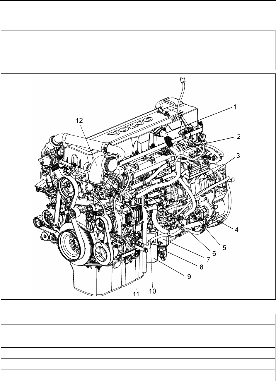
FIGURE 1: D13F ENGINE, ALTERNATOR SIDE (TYPICAL)
1. Breather Tube 7. Fuel Filter
2. Intake Manifold 8. Fuel/Water Separator
3. Air Compressor 9. Fuel Filter
4. Power Steering Pump 10. Hand-Priming Pump
5. Fuel Pump 11. Crankcase Ventilator
6. Engine Electronic Control Unit (EECU) 12. EGR Mixing Chamber

Section 01: ENGINE
PA1561 7
FIGURE 2: D13F ENGINE, TURBO SIDE (TYPICAL)
13. Exhaust Manifold 20. Oil Filters
14. Valve Cover 21. Oil Pan
15. Engine Pre-Heater Element (Optional) 22. EGR Cooler
16. DRV Valve 23. Turbocharger
17. Coolant Pump 24. Starter Motor
18. Coolant Filter 25. EGR Valve
19. Venturi Pipe
1.3 ENGINE OIL
1.3.1 General
Keep the engine oil at the proper level and change it at the recommended intervals. Always replace the
oil filters at the same time as when the oil is changed.
1.3.2 Oil Quality
Volvo North America recognizes engine oils that meet or exceed the standards given by American
Petroleum Institute (API) for the oil classifications listed in this manual. Only oils licensed to carry the API

Section 01: ENGINE
PA1561 8
symbol should be used. Lubricants meeting API standards have provided maximum engine life when
used together with the recommended oil and oil filter change intervals.
EO-O Premium Plus (or VDS-4) diesel engine oil is mandatory for use in all 2007 emission compliant
Volvo engines. Chassis equipped with a 2007 emission compliant engine, which can be identified by the
presence of a Diesel Particulate Filter (DPF), also require the use of Ultra Low Sulfur Diesel (ULSD) fuel.
EO-O Premium Plus oils exceed the new API service category CJ-4.
CAUTION
DO NOT add extra oil additives. Additives such as break-in oils, top oils, graphitizers, and friction-
reducing liquids are not necessary and can harm the engine.
1.3.3 Oil Change Intervals
The length of time an engine can operate before an oil change depends on the quality oil used, the type
of fuel used, fuel consumption, engine oil consumption, vehicle application, level of dust in the air, and
fuel consumption. The change intervals given in this manual are maximum intervals. If the vehicle is
operating in heavy-duty operation, dusty or off-road conditions, etc., reduce the intervals for more
frequent oil changes.
NOTE
Use the information in the table below to determine the operating condition and usage applicable to your
vehicle.
Engine Operating Condition Medium Heavy Severe
Total Fuel Consumption (mpg) More than 6 More than 4.7 More than 3.7
Total Fuel Consumption (L/100 KM) Less than 39 Less than 50 Less than 64
Engine Oil and Filter Change
Interval, miles (km) – 41 U.S. quarts (39L)
Oil capacity
35,000 (55 000) 25,000 (40 000) 15,000 (24 000)
NOTE: If idle time is greater than 25%, use the next lower drain interval.
Section 01: ENGINE
PA1561 9
NOTE
Oil filters should always be changed when
changing the oil.
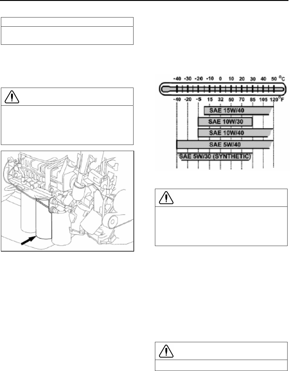
1.3.4 Oil Filters
There are three filters on the engine, one of
which is a bypass filter. This should be changed
at the same time as the full-flow filter(s).
CAUTION
Volvo branded oil filters are designed to
provide the proper level of filtration and
protection for Volvo engines. Filters that do
not meet the same stringent requirements
may void engine warranty.
FIGURE 3: D13F OIL FILTERS
1.3.5 Synthetic Lubrication
Synthetic oils are offered by some oil suppliers
as an alternative to the traditional, petroleum
based oils for engines. These oils may be used
in Volvo engines, provided they meet the quality
levels specified on the previous pages, that is:
both VDS-4 and EO-O Premium Plus.
The use of synthetic oils does not permit the
extension of the recommended oil change
intervals.
1.3.6 Oil Viscosity
The viscosity grade defines the thickness of the
oil. The oil must be thin enough at low
temperatures for easy cold starts and thick
enough to protect at high temperatures. An oil is
not fully defined until both the API quality
classification and the viscosity grade are
specified.
Choose the viscosity grade for the typical
ambient temperature for the application.
Multigrade oils have a broad range that suit
operation in changing temperature.
Volvo North America recommends the
viscosities shown in the viscosity/temperature
table for Volvo engines.
1.3.7 Oil Additives
CAUTION
Extra oil additives must never be added to
any engine oil used. Additives such as break-
in oils, top oils, graphitizers, and friction
reducing liquids are not necessary and may
even harm the engine.
Using oils to the quality standards
recommended in this manual makes the use of
extra oil additives unnecessary, as these oils
already contain a balanced treatment of
additives.
1.3.8 Oil Consumption
Once the engine is stopped, check the oil level
daily. If the engine has just been stopped and it
is warm, wait approximately five minutes to allow
the oil to drain back to the oil pan before
checking. Add oil as necessary.
CAUTION
DO NOT overfill engine with oil.
All diesel engines are designed to consume
some oil, so it is normal to add oil periodically.
An engine used in heavy-duty operation will
consume more oil than one in normal operation.
Section 01: ENGINE
PA1561 10
1.3.9 Oil Change
WARNING
A hot engine or engine oil can be dangerous.
Serious burns can result from contact with a
hot engine or oil. Take precautions when
draining the oil. Wear gloves or let the engine
cool down before draining.
WARNING
When draining the oil, use the proper tools
and keep away as far as possible. Raise the
elbow so the forearm is parallel to the ground
to prevent oil running down the arm, causing
burns.
CAUTION
Always dispose of all lubricants (motor oil,
coolant, gear box oils, etc) and filters
according to Federal or local regulations.
Used oil disposed of in nature or waterways
contaminates our drinking water and kills
wildlife.
WARNING
Prolonged contact with used engine oil may
be harmful. Use rubber gloves when handling
used oil. Wash skin thoroughly if it comes in
contact with used oil.
It is important to drain as much oil as possible.
Try to change oil immediately after driving, when
the oil is warm. Always replace the oil filters
when changing the oil.
Component Capacity (L)
Oil pan 24 min — 32 max
Engine block 4.5
Filters (3) 6
Total oil fill (empty) 42.5
NOTE
Since about 1 liter of oil remains in the engine
after draining, approximately 38 liters will be
needed for a complete oil change.
1.3.10 Oil Filters Change
WARNING
Hot oil can cause severe burns. DO NOT
allow hot oil to contact the skin. When
changing oil, wear protective gloves.
CAUTION
Volvo-branded oil filters are designed to
provide the proper level of filtration and
protection for Volvo engines. Filters that do
not meet the same stringent requirements
may cause unsatisfactory results.
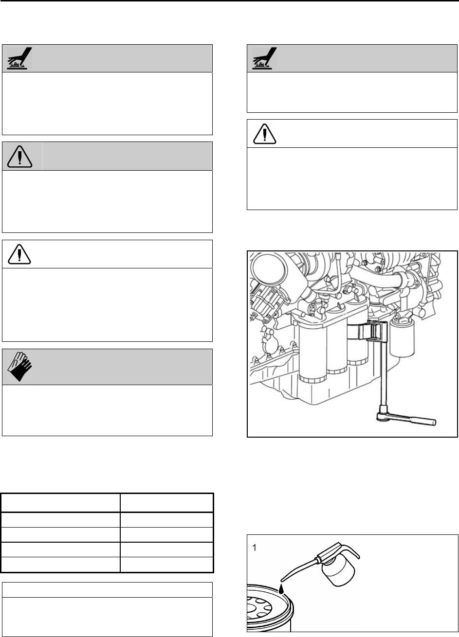
• Clean around the oil filter housing and
remove the filters using the oil filter
wrench or the oil filter socket.
FIGURE 4: OIL FILTER WRENCH
• Prefill the new oil filters with approved
engine oil. Also, lubricate the filter gaskets
with engine oil (1). Hand tighten the oil
filters until they contact the sealing surface
of the oil filter housing (2). Manually
tighten the oil filters an additional ¾ to 1
full turn (3).

Section 01: ENGINE
PA1561 11
FIGURE 5: OIL FITER REPLACEMENT
• Start the engine and check for leaks
around the oil filter housing and filters.
• Check the oil level. Add approved engine
oil to the recommended level, if
necessary. Do not overfill.
1.3.11 Checking the Oil Level
Ensure that the vehicle is parked on level
ground before checking the oil level. Wait five
minutes after shutting off the engine and then
proceed with checking the oil.
CAUTION
DO NOT let the oil level fall below the marking
on the dipstick. DO NOT overfill so the level is
above the upper marking on the dipstick. This
could lead to excessive oil temperature and/or
poor crankcase breather performance. Add oil
through the oil filler pipe as required in order
to maintain level within the safe range.
FIGURE 6: ENGINE OIL FILLING TUBE
FIGURE 7: ENGINE OIL LEVEL DIPSTICK
1.4 POWER PLANT ASSEMBLY REMOVAL
To access the engine or engine-related
components, the vehicle power plant assembly
must be removed as a whole unit by means of a
slide-out cradle. The power plant assembly
includes the engine, transmission (including
retarder if so equipped), air compressor,
alternator and transmission oil cooler.
Remove the power plant assembly as follows:
CAUTION
Tag hoses and cables for identification before
disconnecting in order to facilitate reinstallation.
Plug all openings to prevent dirt from entering
the system.
NOTE
No parts within the EECU are serviceable. If
found defective, replace the EECU as a unit.
• Preparation
1. Close the heater lines shut-off valves.
2. Disconnect the battery or batteries from the
starting system by removing one or both of
the battery cables from each battery system.
With the electrical circuit disrupted,
accidental contact with the starter button will
not produce an engine start.
Section 01: ENGINE
PA1561 12
WARNING
Due to the heavy load of the rear bumper
assembly, it must be adequately supported
before attempting to remove it.
3. Remove the rear bumper assembly from the
vehicle. Refer to Section 18 BODY, under
«Rear Bumper Removal».
4. If applicable, disconnect the block heater
connector located near the EGR mixing
chamber.
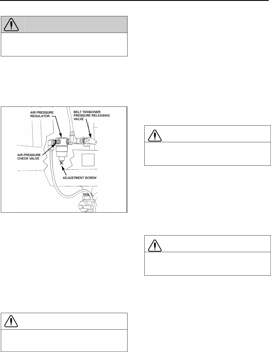
FIGURE 8: BELT TENSIONER VALVE 12200
5. Locate the A/C compressor belt tensioner
pressure releasing valve (Fig. 8). Turn
pressure releasing valve handle
counterclockwise in order to release pressure
in belt-tensioner air bellows and loosen belt.
Remove the A/C compressor belt.
6. To release all pressure from the air system.
Refer to Section 12, BRAKES & AIR
SYSTEM for instructions.
7. Disconnect and remove the engine-air intake
duct mounted between air cleaner housing
and turbocharger inlet.
CAUTION
To avoid damage to turbocharger, cover the
turbocharger inlet opening to prevent foreign
material from entering.
8. Disconnect and remove the air intake duct
mounted between the air cooler outlet and
the engine intake.
9. Disconnect and remove the air intake duct
mounted between the turbocharger outlet
and the air cooler inlet.
10. Disconnect and remove section of coolant
pipe assembly mounted between the radiator
outlet and the water pump inlet.
11. Disconnect and remove a section of coolant
pipe assembly mounted between the
thermostat housing and the radiator inlet, if
applicable.
12. Disconnect the electric fan-clutch connector
located near the cooling fan right angle
gearbox.
13. Disconnect the cooling fan drive shaft.
CAUTION
To avoid damage to cooling fan right angle
gearbox, make sure the power plant cradle
clears the gearbox when pulling the engine out.
14. Disconnect surge tank hoses connected to
the thermostat housing, the pump inlet and to
the transmission oil cooler.
15. Disconnect and remove the exhaust pipe
mounted between the flexible coupling and
the pipe going to the Aftertreatment Device
(ATD). If necessary, refer to Section 04
EXHAUST SYSTEM under “Muffler Removal
and Installation».
CAUTION
To avoid damage to turbocharger, cover the
turbocharger outlet opening to prevent foreign
material from entering.
16. Remove the power steering pump.
17. Close engine fuel supply shutoff valve on
primary fuel filter or Fuel Pro. Disconnect the
fuel line located above fuel filters and
connected to inlet port. On vehicles equipped
with the optional fuel filter/water separator,
disconnect the connector and remove cable
ties from cradle.
• With Vehicle Raised
18. Using the quick-connect drain hose, drain
the engine cooling system. Refer to Section
05 COOLING under «Draining Cooling System».

Section 01: ENGINE
PA1561 13
19. From under the vehicle, disconnect the
propeller shaft as detailed in Section 09,
under heading «Propeller Shaft Removal».
20. On vehicles equipped with an automatic
transmission provided with a hydraulic output
retarder, disconnect steel-braided airline from
pressure regulator output. The pressure
regulator is mounted in the upper section of
engine compartment backwall and is
accessible through the engine compartment
R.H. side door.
21. Remove the retaining bolts, washers and
nuts securing the power plant cradle to the
vehicle rear subframe.
22. Disconnect transmission harness from
transmission housing.
• With Vehicle Lowered
23. Disconnect the air compressor discharge,
governor steel-braided airlines and manual
filling airlines from compressor. Remove
retaining clips.
24. Disconnect the hose connecting the
compressor head to the sump tank, if
applicable.
25. Disconnect ground cables from rear
subframe ground-stud located close to the
starter motor.
26. Disconnect alternators cooling duct and put
aside.
27. Inside rear electrical compartment,
disconnect starter, alternators and heater
cables. Also disconnect AFSS cable if
applicable.
28. Disconnect Aftertreatment Device (ATD)
control cable.
29. Disconnect VIH (vehicle interface harness)
connector.
30. Disconnect fuel return line from bulkhead
fixed on engine cylinder head end.
31. Unfasten and put aside engine compartment
lighting fixture and turbocharger fire
suppression nozzle if applicable.
32. Disconnect turbo boost pressure gauge
airline from engine air intake, if applicable.
33. Disconnect the engine coolant hose near the
starter.
34. On partition wall, disconnect connector C397
located between engine compartment and
main power compartment.
35. Inspect the power plant assembly to ensure
that nothing will interfere when sliding out the
cradle. Check for connections or hoses not
mentioned in this list as some vehicles are
equipped with special or aftermarket
components.
NOTE
Check if any spacer(s) have been installed
between power plant cradle and vehicle rear
subframe, and if so, note position of each
washer for reinstallation purposes.
36. Using a forklift, with a minimum capacity of
4,000 lbs (1 800 kg), slightly raise the power
plant cradle.
37. Pull engine out slowly from the engine
compartment. Make sure all lines, wiring and
accessories are disconnected and are not
tangled.
CAUTION
Due to the minimum clearance between the
power plant equipment and the top of the
engine compartment, extreme care should be
used to raise the power plant cradle, just
enough to free the cradle. Clearance between
power plant cradle and mounting rail should
range between ¼» and ½» (6-12 mm).

Section 01: ENGINE
PA1561 14
FIGURE 9: ENGINE COMPARTMENT H3 COACHES (TYPICAL) 01193
1.5 POWER PLANT ASSY. INSTALLATION
To install a power plant assembly, follow the
same procedure as in «Power Plant Assembly
Removal» except in reverse order, then proceed
with the following:
1. Torque the power plant cradle mounting
bolts to 190 lbf-ft (255 Nm).
2. Refill cooling system with saved fluid (refer
to Section 05 COOLANT SYSTEM).
3. Once engine fuel system has been drained,
it will aid restarting if fuel filters are filled with
fuel oil (refer to Section 03 FUEL SYSTEM).
4. Start engine for a visual check. Check fuel,
oil, cooling, pneumatic and hydraulic system
connections for leakage. Test operation of
engine controls and accessories.
1.6 ENGINE MOUNTS
The power plant assembly is mounted to the
cradle by means of rubber mounts and supports.
Two engine support brackets are used at the
front of the engine while two rubber mounts are
mounted underneath the engine & radiator fan
drive mechanism support and the engine &
alternator support (Fig. 10).
It is recommended that new rubber mounts be
installed at each major overhaul.
NOTE
Refer to the table on the following page for
engine cradle tightening torques.

Section 01: ENGINE
PA1561 15
FIGURE 10: VOLVO ENGINE POWER PLANT CRADLE INSTALLATION
DRY TORQUES
REFERENCE DESCRIPTION Lbf-ft Nm
A SCREW, CAP HEXAGONAL HEAD M8 – 1.25 G8.8 16 22
B SCREW, CAP HEXAGONAL HEAD M8 – 1.25 G10.9 22 30
C SCREW, CAP HEXAGONAL HEAD M10 – 1.5 G10.9 43 58
D SCREW, CAP HEXAGONAL HEAD M12 – 1.75 G8.8 60 81
E SCREW, CAP HEXAGONAL HEAD M14 – 2.0 G8.8 90 122
F SCREW, CAP HEXAGONAL HEAD M16 – 2.0 G8.8 140 190
G SCREW, CAP HEXAGONAL HEAD M16 – 2.0 G10.9 190 258
H SCREW, CAP HEXAGONAL HEAD M20 – 2.5 G10.9 450 610
Section 01: ENGINE
PA1561 16
2. DETROIT DIESEL SERIES 60 ENGINE
The DDC series 60 engine is a 6-cylinder, four-
cycle, 14.0 liters Detroit Diesel series 60 engine,
equipped with an electronic control system
(DDEC VI).
Complete maintenance and repair information
on the engine will be found in the current
DETROIT DIESEL SERIES 60 2007 ON-
HIGHWAY SERVICE MANUAL 6SE2007. This
essential manual contains complete instructions
on operation, adjustment (tune-up), preventive
maintenance and lubrication, parts verification,
repair or replacement. This manual’s sections
cover complete systems such as:
• Engine main assembly;
• Fuel system;
• Lubrication system;
• Cooling system;
• Fuel, lubricating oil and coolant;
• Air intake system;
• Exhaust system;
• Exhaust gas recirculation components;
• Electrical equipment;
• Operation and verification;
• Engine tune-up;
• Preventive maintenance;
• Storage;
Refer to Series 60 DDEC VI Troubleshooting
Guide published by Detroit Diesel for more
complete information on diagnosis of
components and system problems.
Procedures for engine removal and installation
are given at the end of this section. The DDEC
system is self-diagnostic. It can identify faulty
components and other engine-related problems
by providing the technician with diagnostic
codes.
2.1 DDEC VI SYSTEM
DDEC VI (Detroit Diesel Electronic Control) is a
system that monitors and determines all values
required for the operation of the engine. A
diagnostic interface is provided to connect to an
external diagnosis tester. Besides the engine
related sensors and the engine-resident control
unit, the Motor Control Module (MCM), this
system has a chassis-mounted control unit for
vehicle engine management, the Common
Powertrain Controller (CPC). The connection to
the vehicle is made via a CAN interface which
digitally transmits the nominal values (e.g.
torque, engine speed specification, etc.) and the
actual values (e.g. engine speed, oil pressure,
etc.).
DDEC VI controls the timing and amount of fuel
injected by the electronic unit injectors (EUI).
The system also monitors several engine
functions using electrical sensors, which send
electrical signals to the Motor Control Module
(MCM). The MCM computes the electrical
signals and determines the correct fuel output
and timing for optimum power, fuel economy
and emissions. The MCM also has the ability to
display warnings or shut down the engine
completely (depending on option selection) in
the event of damaging engine conditions, such
as low oil pressure or high engine temperature.
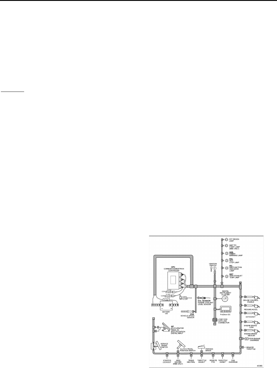
2.2 HARNESSES
There are two major harnesses: the Engine
Harness (EH) and the Vehicle Interface Harness
(VIH). The Engine Harness is installed at the
Detroit Diesel factory and is delivered connected
to all engine sensors, the fuel injection system,
and the MCM.
The OEM supplied Vehicle Interface Harness
connects the CPC to other vehicle systems.
FIGURE 11: VEHICLE INTERFACE HARNESS (GENERAL
APPLICATION SHOWN)
Section 01: ENGINE
PA1561 17
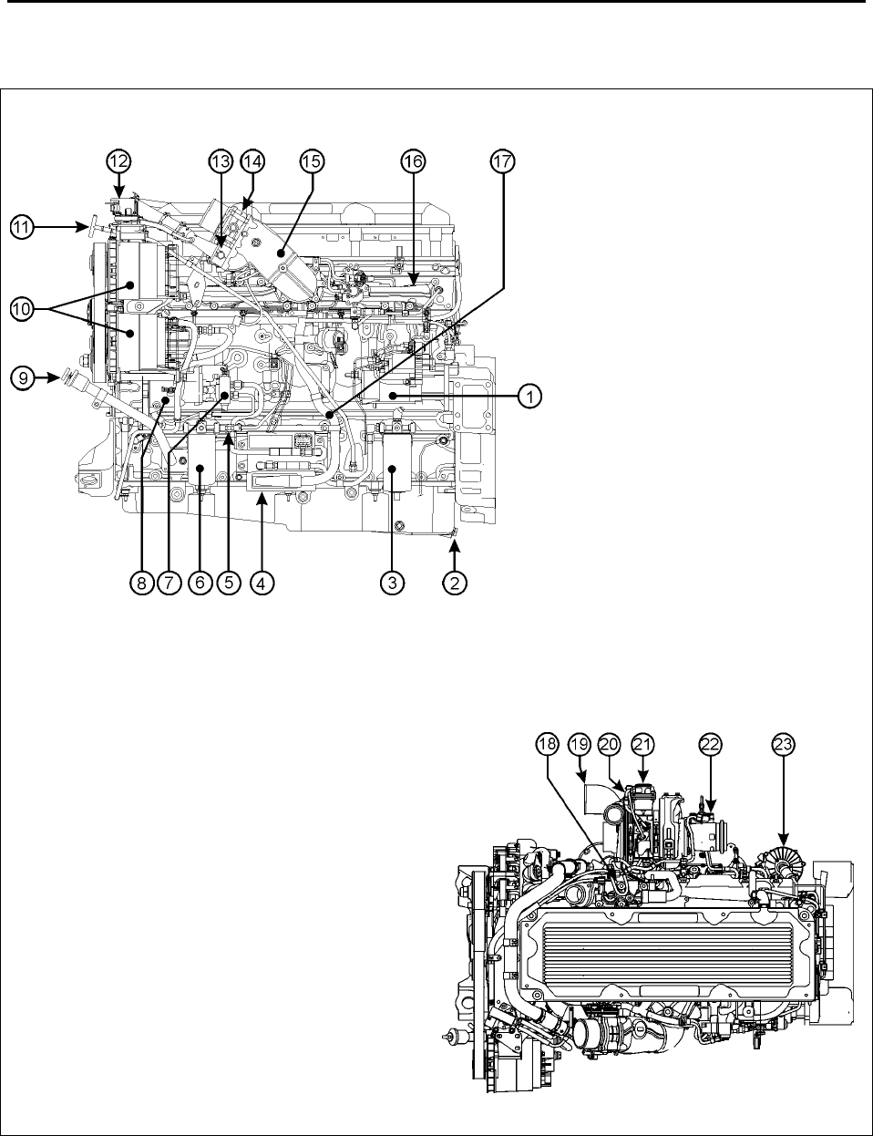
2.3 ENGINE OVERVIEW
1- Starter motor
2- Oil pan drain plug
3- Primary fuel-filter/water-
separator
4- MCM (DDEC VI Electronics)
5- Secondary fuel filter shutoff
valve
6- Secondary fuel filter
7- Fuel pump
8- Air compressor
9- Engine oil filling tube
10- Bosch alternators (2)
11- Engine oil dipstick
12- EGR delta pressure sensor
13- EGR valve
14- Intake throttle
15- EGR mixer
16- Intake manifold
17- Engine Harness
18- Thermostat housing
19- Turbo compressor outlet
20- Actuator coolant return line
21- Electrically controlled actuator
22- HC doser
23- Closed-crankcase breather/oil separator

Section 01: ENGINE
PA1561 18
24- Water pump
25- EGR cooler
26- Oil filter (2)
27- Crankcase breather tube
28- EGR tube
FIGURE 12: DETROIT DIESEL 2007 SERIES 60 ENGINE (TYPICAL) 01179
2.4 DDEC VI SENSORS
• Camshaft Position Sensor (CMP Sensor):
Indicates a specific cylinder in the firing
order.
• Crankshaft Position Sensor (CKP Sensor):
Senses crankshaft position and engine
speed for functions such as fuel control
strategy.
• DPF Inlet Pressure Sensor Measures
pressure between the Diesel Oxidation
Catalyst (DOC) and the Diesel Particulate
Filter (DPF) in the aftertreatment assembly.
• DPF Outlet Pressure Sensor: Measures
pressure on the outlet of the aftertreatment
device in the exhaust system of the vehicle.
• DPF Outlet Temperature Sensor:
Temperature measured at the outlet of the
after-treatment system that is installed within
the exhaust system of the vehicle.
• DOC Inlet Temperature Sensor:
Temperature measured at the outlet of the
after-treatment.
• DOC Outlet Temperature Sensor:
Temperature measured between the DOC
and the DPF in the aftertreatment assembly.
• EGR Delta Pressure Sensor: Senses EGR
pressure for EGR control.
• EGR Temperature Sensor: Senses EGR
exhaust temperature after EGR cooler. Used
for EGR system diagnosis.
• Engine Coolant Temperature Sensor (ECT
Sensor): Senses coolant temperature for
functions such as engine protection, fan
control and engine fueling.
• Engine Oil Pressure Sensor (EOP
Sensor): Senses gallery oil pressure for
functions such as engine protection.
• Engine Oil Temperature Sensor (EOT
Sensor): Senses oil temperature for
functions such as reducing variation in fuel
injection and fan control.
• Fuel Line Pressure Sensor: Senses fuel
line pressure.
• Fuel Compensation Pressure Sensor:
Compensates fuel line pressure.
• Intake Manifold Pressure Sensor (IMP
Sensor): Senses turbo boost for functions
such as smoke control and engine protection.
• Intake Manifold Air Temperature Sensor
(IMT Sensor): Senses pressure. The MCM
uses this information to compute the amount
of air entering the engine.
• Supply Fuel Temperature Sensor (SFT
Sensor): Senses fuel temperature for
functions such as engine fueling.
• Turbo Compressor Temperature Out
Sensor: Senses turbo out air temperature.
• Turbo Speed Sensor (TSS): Monitors turbo
speed for overspeed conditions.
• VGT Position Sensor/EGR Valve Position
Sensor.
• Intake Air Throttle Valve Sensor.
• Exhaust Valve Recirculation Valve (EGR)
Sensor.

Section 01: ENGINE
PA1561 19
2.5 PREVOST INSTALLED SENSORS
• Engine Coolant Level Sensor (ECL
Sensor): Senses coolant level for engine
protection (mounted on coolant surge tank).
• Turbo Compressor In Temperature
Sensor: Senses the air temperature at the
turbo compressor inlet.
• Vehicle Speed Sensor (VSS): Provides a
vehicle speed signal (connected to
transmission).
2.6 MOTOR CONTROL MODULE (MCM)
The Motor Control Module is mounted, on the
starter side of the engine (Fig. 13). Considered
the «Brain» of the DDEC VI system, it provides
overall monitoring and control of the engine. It
does so by comparing input data from the
various sensors to a set of calibration data
stored in the EEPROM (Electrically Erasable,
Programmable, Read-Only Memory) within the
Motor Control Module. After comparing the
input data with the calibration data, the MCM
sends high-current command pulses to the
Electronic Unit Injectors (EUI) to initiate fuel
injection. The MCM also receives feedback
regarding the start and end of injection for a
given cylinder. The EEPROM within the Motor
Control Module is factory programmed by
Detroit Diesel. Reprogramming must be done at
a Detroit Diesel authorized service center.
However, some changes may be performed to
the cruise control and road speed limiter using a
diagnostic data reader (see paragraph «DDEC
VI Diagnostic Codes» in this section).
FIGURE 13: MOTOR CONTROL MODULE (MCM) 01145
2.7 COMMON POWERTRAIN CONTROLLER
(CPC)
The CPC is the interface between the MCM and
the vehicle/equipment for engine control and
manages other vehicle/equipment functions.
Within the CPC, sets of data for specific
applications are stored. These include idle
speed, maximum running speed, and speed
limitation. Customer programmable parameters
are also stored here. The CPC receives data
from the operator (accelerator pedal position,
switches and various sensors) and other
electronic control units. From this data,
instructions are computed for controlling the
engine and transmitted to the MCM via the
proprietary data link.
FIGURE 14: CPC
FIGURE 15: THE CPC COMMUNICATES OVER THE
J1587 AND J1939 DATA LINKS TO THE VEHICLE
2.8 DDEC VI DIAGNOSTICS
2.8.1 Diagnostic system
Diagnostics is a standard feature of DDEC VI.
The purpose of this feature is to provide
information for problem identification and
Section 01: ENGINE
PA1561 20
problem solving in the form of a code. The MCM
and CPC continuously perform self diagnostic
checks and monitor the other system
components. Information for problem
identification and problem solving is enhanced
by the detection of faults, retention of fault codes
and separation of active from inactive codes.
The engine-mounted MCM includes control logic
to provide overall engine management. System
diagnostic checks are made at ignition on and
continue throughout all engine operating modes.
Sensors provide information to the MCM and
CPC regarding various engine and vehicle
performance characteristics. The information is
used to regulate engine and vehicle
performance, provide diagnostic information,
and activate the engine protection system.
The DDEC VI on-board diagnostic system
accessories include the following:
• Check Engine telltale light (AWL);
• Stop Engine telltale light (RSL);
• Stop Engine Override switch (SEO);
• Diagnostic Data Link (DDL) connectors.
The AWL is illuminated and a code is stored if
an electronic system fault occurs. This indicates
the problem should be diagnosed as soon as
possible. The CPC illuminates the AWL and
RSL and stores a malfunction code if a
potentially engine damaging fault is detected.
These codes can be accessed in one of four
ways:
• Commercially available J1587/J1939
diagnostic tools.
• Detroit Diesel Diagnostic Link® (DDDL 7.0).
• Flashing the AWL and RSL with the
SEO/Diagnostic Request Switch.
• Dashboard’s Message Center Display
(MCD).
2.8.2 Check Engine Telltale Light (AWL)
The CPC illuminates the Check Engine telltale,
mounted on the telltale light panel to indicate
that a problem has been detected and that a
code has been stored in the MCM memory.
This light also has a 5-second bulb check when
the ignition is first turned on.
2.8.3 Stop Engine Warning Light (RSL)
This light, also mounted on the telltale light
panel, illuminates to indicate that a major engine
problem is occurring (with the exception of a 5-
second bulb check when the ignition is first
turned on).
2.8.4 Stop Engine Override Switch (SEO)
This switch, mounted on the dashboard, may be
used to extend the 30-second delay period
before engine shutdown when the Stop engine
telltale light is illuminated. This switch can be
repeatedly depressed in order to move the
vehicle out of traffic.
NOTE
The stop engine override switch will be
operative only if it has been depressed before
the end of the 30 second delay period.
CAUTION
The OVERRIDE switch must be used only in
emergency cases, such as to move the
vehicle out of traffic. Excessive use of this
switch can cause serious damage to the
engine.
This switch is also used for DDEC diagnostic
code requests. Press this switch with the engine
at idle or off but with the ignition in the «ON»
position and active codes will be flashed on the
CHECK ENGINE and STOP ENGINE telltale
lights alternately.
2.8.5 Diagnostic Data Link (DDL) Connectors
A connector is mounted on the L.H. footwell
wall. Another connector is located in the rear
electric compartment. They allow the connection
of the Diagnostic Data Reader (DDR) to read
the codes or to access pertinent data on the
condition of the engine. This enables a more
complete analysis of any defect found in the
DDEC system operation. For more information,
see Detroit Diesel Troubleshooting Guide
#6SE492.
2.9 READING DIAGNOSTIC CODES –
FLASHING LIGHT METHOD:
DDEC VI makes use of two types of codes:
Active and inactive. The difference between the
two types of codes is as follows:

Section 01: ENGINE
PA1561 21
Active Codes: Codes that are currently
keeping the Check Engine or Stop Engine
telltale light illuminated. Active codes are flashed
via the Stop Engine Light when checked with the
stop-engine-override switch.
Inactive Codes: These are all the codes
logged in the CPC, which have previously
occurred, (whether or not they are currently
turning on the Stop or Check Engine Light).
Inactive codes are flashed via the Check Engine
telltale light when checked with the stop-engine-
override switch.
In most instances, only the DDR can provide the
information necessary for a quick diagnosis of
the problem. If you just need to read out codes,
however, and do not have a DDR available, the
following procedure will let you read out codes.
Make sure the rear-starting switch (located in
the engine compartment) is in the normal
position. With the ignition ON, the engine idling
or engine shut-off, momentarily depress the
Stop Engine Override (SEO) switch. Active
codes will be flashed on the stop engine telltale,
followed by the inactive codes being flashed on
the check-engine telltale panel. The cycle
repeats itself until the operator depresses the
stop engine override switch again.
Flashing codes provide a four digit number.
Each fault code is flashed twice in order to help
with counting the flashes. If there are no active
faults or if there are no inactive faults the
number “3” is flashed once followed by an ~3s
delay.
FIGURE 16: FLASHING FAULTS CODES
Refer to DDEC Troubleshooting Manual 6SE567
for more information and SAE codes.
NOTE
Active codes are flashed in ascending
numerical flash code order. Inactive codes are
flashed in most recent to least recent order.
NOTE
Fault codes can only be cleared using the
DDR.
NOTE
The listed codes may not be used in all
applications. A default value in the normal
operating range is used by the MCM to
provide for engine operation if a sensor failure
is present.
2.10 DDEC VI CPC DIAGNOSTIC CODES LIST
SPN FMI PID/SID PID/SID
ID
FLASH
CODES FAULT DESCRIPTION
70 2 PID 70 2111 Park Brake Status Not Plausible (Vehicle Moving)
70 19 SID 234 2112 J1939 Park Brake Switch Signal from Source #1 is
erratic
70 13 SID 234 2112 J1939 Park Brake Switch Signal from Source #1 is
missing
70 19 SID 234 2112 J1939 Park Brake Switch Signal from Source #2 is
erratic
70 13 SID 234 2112 J1939 Park Brake Switch Signal from Source #2 is
missing
70 19 SID 234 2112 J1939 Park Brake Switch Signal from Source #3 is
erratic
70 13 SID 234 2112 J1939 Park Brake Switch Signal from Source #3 is
missing
84 21 PID 84 2113 Vehicle Speed Failure

Section 01: ENGINE
PA1561 22
SPN FMI PID/SID PID/SID
ID
FLASH
CODES FAULT DESCRIPTION
84 3 PID 84 2113 Vehicle Speed Sensor Circuit Failed High
84 4 PID 84 2113 Vehicle Speed Sensor Circuit Failed Low
84 2 PID 84 2113 VSS Anti Tamper Detection via Virtual Gear Ratio
84 8 PID 84 2113 VSS Anti Tamper Detection via Fixed Frequency
Device
84 6 PID 84 2113 VSS Anti-Tamper Detection via ABS Vehicle Speed
Comparison
84 19 PID 84 2113 J1939 Wheel-Based Vehicle Speed Signal from
Source#1 is erratic
84 13 PID 84 2113 J1939 Wheel-Based Vehicle Speed Signal from
Source#1 is missing
84 19 SID 84 2113 J1939 Wheel-Based Vehicle Speed Signal from
Source#2 is erratic
84 13 PID 84 2113 J1939 Wheel-Based Vehicle Speed Signal from
Source#2 is missing
84 19 PID 84 2113 J1939 Wheel-Based Vehicle Speed Signal from
Source#3 is erratic
84 13 PID 84 2113 J1939 Wheel-Based Vehicle Speed Signal from
Source#3 is missing
84 20 PID 84 2113 Vehicle Speed Sensor Drifted High Error (VSS
signal not plausible)
91 13 PID 91 2114 Accelerator Pedal Learn Error
91 3 PID 91 2114 Accelerator Pedal Circuit Failed High
91 4 PID 91 2114 Accelerator Pedal Circuit Failed Low
91 8 PID 91 2114 Pwm Accelerator Pedal Signal 1 Frequency Out Of
Range
91 14 PID 91 2114 Pwm Accelerator Pedal Not Learned
91 7 PID 91 2114 Pwm Accelerator Pedal Idle Not Recognized
91 31 PID 91 2114 Pwm Accelerator Pedal Learned Range to Large
91 3 PID 91 2114 Accelerator Pedal Signal Circuit Failed High
91 9 SID 231 2615 J1939 EEC2 Message is missing
98 0 PID 98 2115 Oil Level High
98 18 PID 98 2115 Oil Level Low
98 1 PID 98 2115 Oil Level Very Low
100 18 PID 100 2121 Oil Pressure Low
100 1 PID 100 2121 Oil Pressure Very Low
107 0 PID 107 2122 Air Filter Restriction High
107 4 PID 107 2122 Air Filter Signal Circuit Failed Low
107 3 PID 107 2122 Air Filter Signal Circuit Failed High
110 16 PID 110 2123 Coolant Temperature High

Section 01: ENGINE
PA1561 23
SPN FMI PID/SID PID/SID
ID
FLASH
CODES FAULT DESCRIPTION
110 0 PID 110 2123 Coolant Temperature Very High
111 18 PID 111 2124 Coolant Level Low
111 3 PID 111 2124 Coolant Level Circuit Failed High
111 4 PID 111 2124 Coolant Level Circuit Failed Low
111 1 PID 111 2124 Coolant Level Very Low
168 0 PID 168 2125 Battery Voltage Very Low
168 0 PID 168 2125 Battery Voltage High
168 18 PID 168 2125 Battery Voltage Low
168 14 PID 168 2125 Opt Idle Detected Charging System or Battery
Failure
168 14 PID 168 2125 ECU powerdown not completed (Main Battery
Terminal Possibly Floating)
171 2 PID 171 2131 Ambient Temperature Sensor Data Erratic
171 14 PID 171 2131 J1587 Ambient Air Temp Sensor Data Not
Received This Ign Cycle
171 9 PID 171 2131 J1587 Ambient Air Temp Sensor Data Message
Stopped Arriving
191 9 SID 231 2615 J1939 ETC1 Message is missing
191 19 SID 231 2132 J1939 Transmission Output Shaft Speed Signal is
erratic
191 13 SID 231 2132 J1939 Transmission Output Shaft Speed Signal is
missing
247 9 PID 247 2615 MCM Engine Hours Data not received or stopped
arriving
247 10 PID 247 2615 MCM Engine Hours Data increasing at an
implausible rate
247 0 PID 247 2615 MCM Engine Hours Data higher than expected
247 1 PID 247 2615 MCM Engine Hours Data lower than expected
523 19 PID 163 2133 J1939 Transmission Current Gear Signal is erratic
523 13 PID 163 2133 J1939 Transmission Current Gear Signal is missing
524 9 SID 231 2615 J1939 ETC2 Message is missing
527 9 SID 231 2615 J1939 CCVS Message from Source #1 is missing
527 9 SID 231 2615 J1939 CCVS Message from Source #2 is missing
527 9 SID 231 2615 J1939 CCVS Message from Source #3 is missing
558 2 SID 230 2134 Idle Validation Switch Inputs Reversed
558 5 SID 230 2134 Idle Validation Switch 2 Circuit Failed Low
558 6 SID 230 2134 Idle Validation Switch 2 Circuit Failed High
558 4 SID 230 2134 Idle Validation Switch 1 Circuit Failed Low
558 3 SID 230 2134 Idle Validation Switch 1 Circuit Failed High

Section 01: ENGINE
PA1561 24
SPN FMI PID/SID PID/SID
ID
FLASH
CODES FAULT DESCRIPTION
596 19 SID 244 2135 J1939 Cruise Control Enable Switch Signal from
Source #1 is erratic
596 13 SID 244 2135 J1939 Cruise Control Enable Switch Signal from
Source #1 is missing
596 19 SID 244 2135 J1939 Cruise Control Enable Switch Signal from
Source #2 is erratic
596 13 SID 244 2135 J1939 Cruise Control Enable Switch Signal from
Source #2 is missing
596 19 SID 244 2135 J1939 Cruise Control Enable Switch Signal from
Source #3 is erratic
596 13 SID 244 2135 J1939 Cruise Control Enable Switch Signal from
Source #3 is missing
597 2 SID 246 2141 Service Brake Status Not Plausible
597 19 SID 246 2141 J1939 Service Brake Switch Signal from Source #1
is erratic
597 13 SID 246 2141 J1939 Service Brake Switch Signal from Source #1
is missing
597 19 SID 246 2141 J1939 Service Brake Switch Signal from Source #2
is erratic
597 13 SID 246 2141 J1939 Service Brake Switch Signal from Source #2
is missing
597 19 SID 246 2141 J1939 Service Brake Switch Signal from Source #3
is erratic
597 13 SID 246 2141 J1939 Service Brake Switch Signal from Source #3
is missing
599 4 SID 243 2142 Cruise Control SET and RESUME Circuits Failed
Low
600 19 SID 243 2143 J1939 Cruise Control Coast Switch Signal from
Source #1 is erratic
600 13 SID 243 2143 J1939 Cruise Control Coast Switch Signal from
Source #1 is missing
600 19 SID 243 2143 J1939 Cruise Control Coast Switch Signal from
Source #2 is erratic
600 13 SID 243 2143 J1939 Cruise Control Coast Switch Signal from
Source #2 is missing
600 19 SID 243 2143 J1939 Cruise Control Coast Switch Signal from
Source #3 is erratic
600 13 SID 243 2143 J1939 Cruise Control Coast Switch Signal from
Source #3 is missing
602 19 SID 242 2144 J1939 Cruise Control Accelerate Switch Signal
from Source #1 is erratic
602 13 SID 242 2144 J1939 Cruise Control Accelerate Switch Signal
from Source #1 is missing
602 19 SID 242 2144 J1939 Cruise Control Accelerate Switch Signal
from Source #2 is erratic
602 13 SID 242 2144 J1939 Cruise Control Accelerate Switch Signal
from Source #2 is missing

Section 01: ENGINE
PA1561 25
SPN FMI PID/SID PID/SID
ID
FLASH
CODES FAULT DESCRIPTION
602 19 SID 242 2144 J1939 Cruise Control Accelerate Switch Signal
from Source #3 is erratic
602 13 SID 242 2144 J1939 Cruise Control Accelerate Switch Signal
from Source #3 is missing
608 14 SID 250 2145 J1708 Data Link Failure
609 12 SID 233 2145 CPC2 Hardware Failure
615 9 SID 231 2615 J1939 DM1 Message from Transmission is missing
625 13 SID 248 2151 ECAN ID_1629 Diagnostic Message Not Received
This Ignition Cycle
625 9 SID 248 2151 ECAN ID_1629 Diagnostic Message No Longer
Being Received
625 10 SID 248 2151 ECAN ID_1629 Reporting Inconsistent Number of
Frames
625 2 SID 248 2151 ECAN ID_1629 Diagnostic Message Reporting
Data Not Available
625 14 SID 248 2151 ECAN ID_1629 Diagnostic Message Reporting an
Unknown MUID
625 9 SID 248 2151 Incorrect MCM System ID Received
625 9 SID 248 2151 MCM System ID Not Received or Stopped Arriving
625 4 SID 248 2151 ECAN Link Circuit Failure
628 14 SID 254 2151 XFLASH Static Fault Code Memory Page Read
Write Failure
628 13 SID 155 2615 20ms ECU OS Task Locked in an Endless Loop
628 13 SID 155 2615 20ms ECU OS Task Timed out Prior to Completion
628 13 SID 155 2615 1000ms ECU OS Task Locked in an Endless Loop
628 13 SID 155 2615 1000ms ECU OS Task Timed out Prior to
Completion
629 2 SID 254 2151 CPC Hardware/Software Mismatch
629 12 SID 254 2151 DDEC Data Xflash Write Error. Replace CPC2.
630 2 SID 253 2152 EEPROM Checksum Failure
630 2 SID 253 2152 EEPROM Checksum Failure for the SCR Block
630 13 SID 253 2152 SCR Number Out of Range
630 14 SID 155 2615 MCM Fault Codes Unavailable via J1939 and
J1587
630 14 SID 155 2615 MCM Fault Code Table Inconsistant — Upgrade
MCM Software
630 14 SID 155 2615 Insufficient Static Fault Code Storrage Memory —
Upgrade CPC Software

Section 01: ENGINE
PA1561 26
SPN FMI PID/SID PID/SID
ID
FLASH
CODES FAULT DESCRIPTION
630 14 SID 155 2615 MCM Fault Code Table Inconsistant — Upgrade
MCM Software
639 14 SID 231 2153 J1939 Data Link Failure
701 3 SID 26 2211 Digital Output 4 09 Circuit Failed High
701 4 SID 26 2211 Digital Output 4 09 Circuit Failed Low
702 3 SID 40 2212 Digital Output 3 17 Circuit Failed High
702 4 SID 40 2212 Digital Output 3 17 Circuit Failed Low
703 3 SID 51 2213 Digital Output 3 09 Circuit Failed High
703 4 SID 51 2213 Digital Output 3 09 Circuit Failed Low
704 3 SID 52 2214 Digital Output 4 07 Circuit Failed High
704 4 SID 52 2214 Digital Output 4 07 Circuit Failed Low
705 3 SID 53 2215 Digital Output 1 13 Circuit Failed High
705 4 SID 53 2215 Digital Output 1 13 Circuit Failed Low
706 3 SID 54 2221 Digital Output 3 10 Circuit Failed High
706 4 SID 54 2221 Digital Output 3 10 Circuit Failed Low
707 3 SID 55 2222 Digital Output 2 10 Circuit Failed High (CEL / AWL
Lamp)
707 4 SID 55 2222 Digital Output 2 10 Circuit Failed Low (CEL / AWL
Lamp)
708 3 SID 56 2223 Digital Output 3 12 Circuit Failed High
708 4 SID 56 2223 Digital Output 3 12 Circuit Failed Low
709 3 SID 257 2224 Digital Output 3 16 Circuit Failed High
709 4 SID 257 2224 Digital Output 3 16 Circuit Failed Low
710 3 SID 258 2225 Digital Output 4 06 Circuit Failed High
710 4 SID 258 2225 Digital Output 4 06 Circuit Failed Low
711 3 SID 259 2231 Digital Output 1 05 Circuit Failed High
711 4 SID 259 2231 Digital Output 1 05 Circuit Failed Low
712 3 SID 260 2232 Digital Output 1 04 Circuit Failed High
712 4 SID 260 2232 Digital Output 1 04 Circuit Failed Low
713 3 SID 261 2234 Digital Output 3 07 Circuit Failed High
713 4 SID 261 2234 Digital Output 3 07 Circuit Failed Low
713 5 SID 261 2234 Digital Output 3 07 Open Circuit
713 7 SID 261 2234 TOP2 Shift Failure
714 3 SID 262 2235 Digital Output 3 08 Circuit Failed High
714 4 SID 262 2235 Digital Output 3 08 Circuit Failed Low
714 5 SID 262 2235 Digital Output 3 08 Open Circuit
715 3 SID 263 2241 Digital Output 4 10 Circuit Failed High
904 9 SID 231 2615 J1939 EBC2 Message from ABS is missing
904 19 SID 231 2242 J1939 Front Axle Speed Signal is erratic
904 13 SID 231 2242 J1939 Front Axle Speed Signal is missing
972 2 SID 203 2243 Throttle inhibit switch signal not plausible due to
excess vehicle speed
973 9 SID 231 2615 J1939 EBC1 Message is missing
973 13 SID 231 2244 J1939 Engine Retarder Selection Signal Missing

Section 01: ENGINE
PA1561 27
SPN FMI PID/SID PID/SID
ID
FLASH
CODES FAULT DESCRIPTION
973 19 SID 231 2244 J1939 Engine Retarder Selection Signal Erratic
974 2 PID 372 2245 Remote Accelerator Pedal Supply Voltage Out of
Range
974 3 PID 372 2245 Remote Accelerator Pedal Circuit Failed High
974 4 PID 372 2245 Remote Accelerator Pedal Circuit Failed Low
981 0 SID 155 2311 PTO CC+ and CC- Switches Pressed
Simultaneously
986 9 SID 231 2615 J1939 CM1 Message is missing
1267 4 SID 123 2312 Digital Output 4 10 Circuit Failed Low
1267 3 SID 123 2312 Digital Output 4 10 Circuit Failed Open
1321 4 SID 128 2314 Starter Lockout Output Shorted to Ground
1321 3 SID 128 2314 Starter Lockout Output Open Circuit
1590 19 SID 155 2615 Adaptive Cruise Control Message Not Received
1590 9 SID 231 2615 Adaptive Cruise Control Device Reporting Error
1624 9 SID 231 2615 J1939 TCO1 Message is missing
1624 19 SID 231 2315 J1939 Tachograph Vehicle Speed Signal is erratic
1624 13 SID 231 2315 J1939 Tachograph Vehicle Speed Signal is missing
1663 7 SID 123 2321 Optimized Idle Safety Loop Faulted
1716 9 SID 231 2615 J1939 ERC1 Message is missing
1845 9 SID 231 2615 J1939 TCFG2 Message is missing
2623 14 PID 91 2322 Pwm Accelerator Pedal GAS1 and GAS2 Signal
Missing
2623 8 PID 91 2322 Pwm Accelerator Pedal Signal 2 Frequency Out Of
Range
2900 9 SID 231 2615 J1939 ETC7 Message is missing
3510 3 SID 211 2333 Accelerator Pedal Supply Voltage Circuit Failed
High
3510 4 SID 211 2333 Accelerator Pedal Supply Voltage Circuit Failed
Low
3510 4 SID 211 2333 Pwm Accelerator Pedal Supply Voltage Missing
3510 3 SID 211 2333 Accelerator Pedal Supply Voltage Circuit Failed
High
3606 9 SID 231 2615 J1939 ESS Message is missing
3695 2 SID 155 2334 Manual DPF Regen and DPF Inhibit Switch
Rationality Fault
3695 19 SID 155 2334 DPF Regen Inhibit MUX Switch Message Contains
Data Error Indicator
3695 13 SID 155 2334 DPF Regen Inhibit MUX Switch Message Contains
SNV Indicator
3695 9 SID 155 2334 DPF Regen Inhibit MUX Switch Message Stopped
Arriving

Section 01: ENGINE
PA1561 28
SPN FMI PID/SID PID/SID
ID
FLASH
CODES FAULT DESCRIPTION
3695 14 SID 155 2334 DPF Regen Inhibit MUX Switch Message Not
Received this Ign Cycle
3696 19 SID 155 2335 DPF Regen Force MUX Switch Message Contains
Data Error Indicator
3696 13 SID 155 2335 DPF Regen Force MUX Switch Message Contains
SNV Indicator
3696 9 SID 155 2335 DPF Regen Force MUX Switch Message Stopped
Arriving
3696 14 SID 155 2335 DPF Regen Force MUX Switch Message Not
Received this Ign Cycle
2.11 DDEC VI MCM DIAGNOSTIC CODES LIST
SPN FMI PID/SID
PID/SID
ID
FLASH
CODE FAULT DESCRIPTION
27 4 PID 27 1111 EGR Valve Position Circuit Failed Low
27 3 PID 27 1111 EGR Valve Position Circuit Failed High
27 2 PID 27 1111 EGR Valve Position Feedback Failed
27 0 PID 27 1111 EGR Valve Position Feedback Failed (High Box)
27 1 PID 27 1111 EGR Valve Position Feedback Failed (Low Box)
27 14 PID 27 1111 EGR Valve Position Positive Torque Error
27 7 PID 27 1111 EGR Valve Stuck Open
27 19 PID 27 1521 Smart Actuator Indicates EGR Position Error
51 4 SID 51 1112 Intake Air Throttle Circuit Failed Low
51 3 SID 51 1112 Intake Air Throttle Circuit Failed High
51 2 PID 51 1112 Intake Throttle Position Deviation Error
51 0 PID 51 1112 Intake Air Throttle Position High
51 1 PID 51 1112 Intake Air Throttle Position Low
51 7 PID 51 1112 Intake Throttle Auto Calibration Error
94 4 PID 94 1112 Fuel Compensation Pressure Sensor Circuit Failed Low
94 3 PID 94 1112 Fuel Compensation Pressure Sensor Circuit Failed High
94 1 PID 94 1112 Fuel Pressure Too High/Too Low
97 4 PID 97 1615 Water in Fuel Circuit Failed Low
97 3 PID 97 1615 Water in Fuel Circuit Failed High
98 1 PID 98 1114 Oil Level Circuit Failed Low
98 0 PID 98 1114 Oil Level Circuit Failed High
98 13 PID 98 1634 Oil Level Mesaurement, Configuration Error
98 14 PID 98 1634 Oil Level Mesaurement, Oil Level Too Low or Too High
100 4 PID 100 1114 Engine Oil Pressure Circuit Failed Low
100 3 PID 100 1114 Engine Oil Pressure Circuit Failed High
100 1 PID 100 1114 Engine Oil Pressure Low
100 2 PID 100 1114 Oil Pressure Plausibility — Engine Running
100 2 PID 100 1114 Oil Pressure Plausibility — Stop
103 2 PID 103 1115 Turbocharger Speed Not Plausible
103 1 PID 103 1115 Turbo Charger Speed Below Threshold (High Box)
103 0 PID 103 1115 Turbo Charger Speed Above Threshold (Low Box)
103 4 PID 103 1115 Turbo Charger Speed Sensor Circuit Failed Low
103 3 PID 103 1115 Turbo Charger Speed Sensor Circuit Failed High
108 4 PID 108 1211 Barometric Pressure Circuit Failed Low
108 3 PID 108 1211 Barometric Pressure Circuit Failed High
108 2 PID 108 1211 Ambient Pressure Plausibility Fault (Low Box)
108 20 PID 108 1211 Ambient Pressure Plausibility Fault (High Box)

Section 01: ENGINE
PA1561 29
SPN FMI PID/SID
PID/SID
ID
FLASH
CODE FAULT DESCRIPTION
110 4 PID 110 1212 Engine Coolant Outlet Temperature Circuit Failed Low
110 3 PID 110 1212 Engine Coolant Outlet Temperature Circuit Failed High
110 0 PID 110 1212 Coolant Temperature High
110 14 PID 110 1212 Coolant Temperature / Engine Oil Temperature Plausibility Fault
110 2 PID 110 1212 Engine Coolant Sensor (OUT), General Temp. Plausibility Error
132 7 PID 132 1213 Intake Air Throttle Valve Closure Detection- Positive Torque
132 14 PID 132 1213 Intake Air Throttle Valve Closure Detection -Braking Condition
132 14 PID 322 1635 HC-Doser Fuel Pressure Not Plausible
132 1 PID 322 1213 Air Mass Flow Too Low
132 13 PID 132 1213 Air Mass Auto Calibration Failed
158 2 PID 43 1214 Ignition Switch Not Plausible
164 4 PID 164 1215 Rail Pressure Governor Sensor Circuit Failed Low
164 3 PID 164 1215 Rail Pressure Governor Sensor Circuit Failed High
164 0 PID 164 1215 Rail Pressure Governor (High Side) Error
164 0 PID 164 1215 Rail Pressure Governor (Low Side) Error
168 1 PID 168 1221 Battery Voltage Low
168 0 PID 168 1221 Battery Voltage High
171 4 PID 171 1222 Ambient Temperature Circuit Failed Low
171 3 PID 171 1222 Ambient Temperature Circuit Failed High
174 4 PID 174 1223 Fuel Temperature Circuit Failed Low
174 3 PID 174 1223 Fuel Temperature Circuit Failed High
174 2 PID 174 1223 Fuel Temperature Sensor, General Temp. Plausibility
174 0 PID 174 1223 Fuel Temperature Too High
175 4 PID 175 1224 Engine Oil Temperature Circuit Failed Low
175 3 PID 175 1224 Engine Oil Temperature Circuit Failed High
175 14 PID 175 1224 Engine Oil Temperature Sensor Plausibility Fault
175 2 PID 175 1224 Engine Oil Temperature Sensor, General Temp. Plausibility
190 2 PID 190 1225 Engine Speed High
354 4 PID 354 1231 Relative Humidity Circuit Failed Low
354 3 PID 354 1231 Relative Humidity Circuit Failed High
411 4 PID 411 1232 EGR Delta Pressure Sensor Circuit Low
411 3 PID 411 1232 EGR Delta Pressure Sensor Circuit High
411 0 PID 411 1232 EGR Differential Pressure Failed (High Box)
411 1 PID 411 1232 EGR Differential Pressure Failed (Low Box)
411 5 PID 411 1232 EGR Sampling Range Failed
411 13 PID 411 1232 EGR Delta Pressure Sensor Out Of Calibration
411 13 PID 411 1232 EGR Delta Pressure Sensor Out Of Calibration
412 3 PID 412 1233 EGR Temperature Sensor Circuit Failed High
412 4 PID 412 1233 EGR Temperature Sensor Circuit Failed Low
412 20 PID 412 1233 EGR Temperature Drift (High Box)
412 21 PID 412 1233 EGR Temperature Drift (Low Box)
412 2 PID 412 1233 EGR Temperature Sensor, General Temp. Plausibility Error
412 0 PID 412 1512 EGR Temperature Very High
412 16 PID 412 1233 EGR Temperature Sensor / Temperature Too High
615 4 SID 155 1615
Reserved Monitoring Unit For Temperature Diagnostics, Circuit Failed Low
MU_ISP_T_TBD4_SRL
615 3 SID 155 1615
Reserved Monitoring Unit For Temperature Diagnostics, Circuit Failed High
MU_ISP_T_TBD4_SRH
615 4 SID 155 1615
Reserved Monitoring Unit For Temperature Diagnostics, Circuit Failed Low
MU_ISP_T_TBD1_SRL
615 3 SID 155 1615
Reserved Monitoring Unit For Temperature Diagnostics, Circuit Failed High
MU_ISP_T_TBD1_SRH
615 4 SID 155 1615
Reserved Monitoring Unit For Temperature Diagnostics, Circuit Failed Low
MU_ISP_T_TBD2_SRL

Section 01: ENGINE
PA1561 30
SPN FMI PID/SID
PID/SID
ID
FLASH
CODE FAULT DESCRIPTION
615 3 SID 155 1615
Reserved Monitoring Unit For Temperature Diagnostics, Circuit Failed High
MU_ISP_T_TBD2_SRH
615 4 SID 155 1615
Reserved Monitoring Unit For Temperature Diagnostics, Circuit Failed Low
MU_ISP_T_TBD3_SRL
615 3 SID 155 1615
Reserved Monitoring Unit For Temperature Diagnostics, Circuit Failed High
MU_ISP_T_TBD3_SRH
615 4 SID 155 1615 Catalyst Temperature Sensor Circuit High Input (Bank 1 Sensor 1)
615 3 SID 155 1615 Catalyst Temperature Sensor Circuit Low Input (Bank 1 Sensor 1)
615 4 SID 155 1615 Catalyst Temperature Sensor Circuit High (Bank 1 Sensor 2)
615 3 SID 155 1615 Catalyst Temperature Sensor Circuit Low (Bank 1 Sensor 2)
615 4 SID 51 1322 Water Pump 1 Circuit Failed Low
615 3 SID 51 1322 Water Pump 1 Circuit Failed High
615 5 SID 51 1322 Water Pump 1 Circuit Failed Open
615 4 SID 55 1331 Turbo Compound Valve Circuit Failed Low
615 3 SID 55 1331 Turbo Compound Valve Circuit Failed High
615 5 SID 55 1331 Turbo Compound Valve Circuit Failed Open
615 4 SID 259 1335 Turbo Brake Sleeve Circuit Failed Low
615 3 SID 259 1335 Turbo Brake Sleeve Circuit Failed High
615 5 SID 259 1335 Turbo Brake Sleeve Circuit Failed Open
615 4 SID 261 1355 Function 20 Circuit Failed Low
615 3 SID 261 1355 Function 20 Circuit Failed High
615 5 SID 261 1355 Function 20 Circuit Failed Open
615 3 SID 155 1451 Service Push Button Circuit Failed High
615 14 SID 155 1615 Turbocharger/Supercharger Boost System Performance
615 14 SID 155 1615 Starter Electronic Fault / ECU internal (Res)
615 14 SID 155 1615 Starter Jammed (Tooth to Tooth Jam)
615 14 SID 155 1615 Rail Pressure Governor, Valve Stays Open
615 14 SID 155 1615 MU_RPG_INT_MON_SRH, I Term Value Too High
615 14 SID 155 1615 Rail Pressure Governor, Leakage in High Pressure Too High
615 14 SID 155 1615 Rail Pressure Governor Sensor, Signal Drift
615 14 SID 155 1615 Rail Pressure Governor Sensor, Sensor Supply Line Broken
615 4 SID 155 1615 Compressor Differential Pressure Outlet Failed Low
615 3 SID 155 1615 Compressor Differential Pressure Outlet Failed High
615 14 SID 155 1615 Doser Metering and Safety Unit Valve Seals Check
615 14 SID 155 1615 High Pressure Pump, Leakage or TDC Position Wrong
615 4 SID 155 1615 Flap In Front of EGR Cooler Circuit Failed Low
615 3 SID 155 1615 Flap In Front of EGR Cooler Circuit Failed High
615 5 SID 155 1615 Flap In Front of EGR Cooler Circuit Failed Open
615 4 SID 155 1615 Water Pump 2 Circuit Failed Low
615 3 SID 155 1615 Water Pump 2 Circuit Failed High
615 5 SID 156 1615 Water Pump 2 Circuit Failed Open
615 4 SID 157 1615 RCP Test Function 1 Circuit Failed Low
615 3 SID 158 1615 RCP Test Function 1 Circuit Failed High
615 5 SID 159 1615 RCP Test Function 1 Circuit Failed Open
615 4 SID 160 1615 RCP Test Function 2 Circuit Failed Low
615 3 SID 161 1615 RCP Test Function 2 Circuit Failed High
615 5 SID 162 1615 RCP Test Function 2 Circuit Failed Open
615 4 SID 163 1615 Volute Control Valve, Shorted to Ground
615 3 SID 164 1615 Volute Control Valve, Shorted to Battery
615 5 SID 165 1615 Volute Control Valve, Open Load
615 4 SID 166 1615 Volute Shut Off Valve, Shorted to Ground

Section 01: ENGINE
PA1561 31
SPN FMI PID/SID
PID/SID
ID
FLASH
CODE FAULT DESCRIPTION
615 3 SID 167 1615 Volute Shut Off Valve, Shorted to Battery
615 5 SID 168 1615 Volute Shut Off Valve, Open Load
615 4 SID 169 1615 Function 30 Circuit Failed Low
615 3 SID 170 1615 Function 30 Circuit Failed High
615 5 SID 171 1615 Function 30 Circuit Failed Open
615 4 SID 172 1615 Function 31 Circuit Failed Low
615 3 SID 173 1615 Function 31 Circuit Failed High
615 5 SID 174 1615 Function 31 Circuit Failed Open
615 14 SID 155 1453 Smart Remote Actuator 2, No Failsafe Mode, Motor Off
615 9 SID 155 1453 Smart Remote Actuator 2, Failsafe Mode, Motor Off
615 16 SID 155 1453 Smart Remote Actuator 2, Temperature Fault
615 7 SID 155 1453 Smart Remote Actuator 2, Failsafe Mode, Motor On
615 11 SID 155 1453 Smart Remote Actuator 2, Restricted Operability
615 15 SID 155 1453 Smart Remote Actuator 2, Temperature Warning
615 8 SID 155 1453 Smart Remote Actuator 2, Internal Test Running
615 31 SID 155 1453 Smart Remote Actuator 2, Unknown Error Code
615 13 SID 155
1454 Turbocharger Compressor Outlet Differential Pressure Sensor Out Of
Calibration
615 13 SID 155
1454 Turbocharger Compressor Outlet Differential Pressure Sensor Out Of
Calibration
615 19 SID 155 1637 Smart Actuator Indicates Actuator Position Error
625 2 SID 248 1234 Invalid Data on Engine CAN Link
625 9 SID 248 1234 No Data Received from Engine CAN Link
625 9 SID 248 1234 Engine CAN Low Wire Defect — (wire 1)
625 9 SID 248 1234 Engine CAN High Wire Defect — (wire 2)
630 12 SID 253 1452 EEPROM Read / Write Operation Failed
630 13 SID 253 1455 Calibration Data Not Plausible
630 13 SID 253 1455 Calibration Data Not Plausible (CPLD)
634 4 SID 40 1321 Constant Throttle Valve Circuit Failed Low
634 3 SID 40 1321 Constant Throttle Valve Circuit Failed High
634 5 SID 40 1321 Constant Throttle Valve Circuit Failed Open
636 1 SID 21 1235 Crankshaft Position Sensor Signal Voltage Too Low
636 3 SID 21 1235 Crankshaft Position Sensor Open Circuit
636 4 SID 21 1235 Crankshaft Position Sensor Short to Ground
636 8 SID 21 1235 Crankshaft Position Sensor Time Out
636 14 SID 21 1235 Crankshaft Position Sensor Pins Swapped
636 2 SID 21 1235 No Match of Camshaft and Crankshaft Signals
641 4 SID 27 1542 Turbo Control Circuit Failed Low
641 3 SID 27 1542 Turbo Control Circuit Failed High
641 5 SID 27 1542 Turbo Control Circuit Open
641 14 SID 147 1241 Smart Remote Actuator 5 (VGT), No Failsafe Mode, Motor Off
641 9 SID 147 1241 Smart Remote Actuator 5 (VGT), Failsafe Mode, Motor Off
641 7 SID 147 1241 Smart Remote Actuator 5 (VGT), Failsafe Mode, Motor On
641 11 SID 147 1241 Smart Remote Actuator 5 (VGT), Restricted Operability
641 8 SID 147 1241 Smart Remote Actuator 5 (VGT), Internal Test Running
641 31 SID 147 1241 Smart Remote Actuator 5 (VGT), Unknown Error Code
647 4 SID 33 1334 Fan Stage 1 Circuit Failed Low
647 3 SID 33 1334 Fan Stage 1 Circuit Failed High

Section 01: ENGINE
PA1561 32
SPN FMI PID/SID
PID/SID
ID
FLASH
CODE FAULT DESCRIPTION
647 5 SID 33 1334 Fan Stage 1 Circuit Failed Open
651 14 SID 1 1242 Injector Cylinder #1 Needle Control Valve Abnormal Operation
651 10 SID 1 1242 Injector Cylinder #1 Needle Control Valve Abnormal Rate of Change
651 5 SID 1 1242
Injector Cylinder 1, Nozzle Control Valve or Spill Control Valve, Jammed
Closed
651 7 SID 1 1242
Injector Cylinder 1, Nozzle Control Valve or Spill Control Valve, Jammed
Open or Leakage
651 6 SID 1 1242 Injector Cylinder #1 Needle Control Valve, Valve Shorted Circuit
651 31 SID 1 1242 Engine Smoothness Control / Cylinder #1 Value Out of Range
652 14 SID 2 1243 Injector Cylinder #2 Needle Control Valve Abnormal Operation
652 10 SID 2 1243 Injector Cylinder #2 Needle Control Valve Abnormal Rate of Change
652 5 SID 2 1243
Injector Cylinder 2, Nozzle Control Valve or Spill Control Valve, Jammed
Closed
652 7 SID 2 1243
Injector Cylinder 2, Nozzle Control Valve or Spill Control Valve, Jammed
Open or Leakage
652 6 SID 2 1243 Injector Cylinder #2 Needle Control Valve, Valve Shorted Circuit
652 31 SID 2 1243 Engine Smoothness Control / Cylinder #2 Value Out of Range
653 14 SID 3 1244 Injector Cylinder #3 Needle Control Valve Abnormal Operation
653 10 SID 3 1244 Injector Cylinder #3 Needle Control Valve Abnormal Rate of Change
653 5 SID 3 1244
Injector Cylinder 3, Nozzle Control Valve or Spill Control Valve, Jammed
Closed
653 7 SID 3 1244
Injector Cylinder 3, Nozzle Control Valve or Spill Control Valve, Jammed
Open or Leakage
653 6 SID 3 1244 Injector Cylinder #3 Needle Control Valve, Valve Shorted Circuit
653 31 SID 3 1244 Engine Smoothness Control / Cylinder #3 Value Out of Range
654 14 SID 4 1245 Injector Cylinder #4 Needle Control Valve Abnormal Operation
654 10 SID 4 1245 Injector Cylinder #4 Needle Control Valve Abnormal Rate of Change
654 5 SID 4 1245
Injector Cylinder 4, Nozzle Control Valve or Spill Control Valve, Jammed
Closed
654 7 SID 4 1245
Injector Cylinder 4, Nozzle Control Valve or Spill Control Valve, Jammed
Open or Leakage
654 6 SID 4 1245 Injector Cylinder #4 Needle Control Valve, Valve Shorted Circuit
654 31 SID 4 1245 Engine Smoothness Control / Cylinder #4 Value Out of Range
655 14 SID 5 1251 Injector Cylinder #5 Needle Control Valve Abnormal Operation
655 10 SID 5 1251 Injector Cylinder #5 Needle Control Valve Abnormal Rate of Change
655 5 SID 5 1251
Injector Cylinder 5, Nozzle Control Valve or Spill Control Valve, Jammed
Closed
655 7 SID 5 1251
Injector Cylinder 5, Nozzle Control Valve or Spill Control Valve, Jammed
Open or Leakage
655 6 SID 5 1251 Injector Cylinder #5 Needle Control Valve, Valve Shorted Circuit
655 31 SID 5 1251 Engine Smoothness Control / Cylinder #5 Value Out of Range
656 14 SID 6 1252 Injector Cylinder #6 Needle Control Valve Abnormal Operation
656 10 SID 6 1252 Injector Cylinder #6 Needle Control Valve Abnormal Rate of Change
656 5 SID 6 1252
Injector Cylinder 6, Nozzle Control Valve or Spill Control Valve, Jammed
Closed
656 7 SID 6 1252
Injector Cylinder 6, Nozzle Control Valve or Spill Control Valve, Jammed
Open or Leakage
656 6 SID 6 1252 Injector Cylinder #6 Needle Control Valve, Valve Shorted Circuit
656 31 SID 6 1252 Engine Smoothness Control / Cylinder #6 Value Out of Range
657 14 SID 7 1253 Injector Cylinder #7 Needle Control Valve Abnormal Operation

Section 01: ENGINE
PA1561 33
SPN FMI PID/SID
PID/SID
ID
FLASH
CODE FAULT DESCRIPTION
657 10 SID 7 1253 Injector Cylinder #7 Needle Control Valve Abnormal Rate of Change
657 6 SID 7 1253 Injector Cylinder #7 Needle Control Valve, Valve Shorted Circuit
657 31 SID 7 1253 Engine Smoothness Control / Cylinder #7 Value Out of Range
658 14 SID 8 1254 Injector Cylinder #8 Needle Control Valve Abnormal Operation
658 10 SID 8 1254 Injector Cylinder #8 Needle Control Valve Abnormal Rate of Change
658 6 SID 8 1254 Injector Cylinder #8 Needle Control Valve, Valve Shorted Circuit
658 31 SID 8 1254 Engine Smoothness Control / Cylinder #8 Value Out of Range
677 2 SID 39 1255 Starter Switch Inconsistent
677 5 SID 39 1255 Engine Starter Relay Circuit Failed Low
677 4 SID 39 1255 Engine Starter Relay Open Circuit
677 14 SID 39 1255 Starter Electronic Fault / ECU internal (Main)
677 7 SID 39 1255 Engine Starter Relay — Starter Does Not Engage
677 3 SID 39 1255 Engine Starter Relay Shorted to High Source
677 7 SID 39 1255 Engine Starter Relay Jammed
698 4 SID 58 1312 Gridheater Circuit Failed Low
698 3 SID 58 1312 Gridheater Circuit Failed High
698 5 SID 58 1312 Gridheater Circuit Failed Open
715 4 SID 263 1412 High Side Digital Output # 1 Circuit Failed Low
715 3 SID 263 1412 High Side Digital Output # 1 Circuit Failed High
715 5 SID 263 1412 High Side Digital Output # 2 Circuit Failed Open
716 4 SID 264 1413 High Side Digital Output # 2 Circuit Failed Low
723 1 SID 64 1415 Camshaft Position Sensor Signal Voltage Too Low
723 3 SID 64 1415 Camshaft Position Sensor Open Circuit
723 4 SID 64 1415 Camshaft Position Sensor Short to Ground
723 8 SID 64 1415 Camshaft Position Sensor Time Out
723 14 SID 64 1415 Camshaft Position Sensor Pins Swapped
729 4 PID 45 1421 Grid Heater Circuit Failed Low
729 14 PID 45 1421 Grid Heater Special Instructions
729 3 PID 45 1421 Grid Heater Circuit Failed High
729 7 PID 45 1421 Grid Heater Defect
729 0 PID 45 1421 Grid Heater Permanently On
1071 4 SID 60 1314 Fan Stage 2 Circuit Failed Low
1071 3 SID 60 1314 Fan Stage 2 Circuit Failed High
1071 5 SID 60 1314 Fan Stage 2 Circuit Failed Open
1072 4 SID 79 1422 Jake Brake Stage 1 Circuit Failed Low
1072 3 SID 79 1422 Jake Brake Stage 1 Circuit Failed High
1072 5 SID 79 1422 Jake Brake Stage 1 Circuit Failed Open
1073 4 SID 80 1315 Jake Brake Stage 2 Circuit Failed Low
1073 3 SID 80 1315 Jake Brake Stage 2 Circuit Failed High
1073 5 SID 80 1315 Jake Brake Stage 2 Circuit Failed Open
1074 4 SID 81 1345 Exhaust Brake Circuit Failed Low
1074 3 SID 81 1345 Exhaust Brake Circuit Failed High
1074 5 SID 81 1345 Exhaust Brake Circuit Failed Open
1077 14 PID 164 1241 Rail Pressure Governor Error, Open Loop Error
1077 5 PID 164 1423 Rail Pressure Governor Error, Current Governor, Current Too Low
1077 7 PID 164 1423 Rail Pressure Governor Error, Pressure Governor, Pressure Not Plausible
1077 6 SID 155 1423 Rail Pressure Governor Error, Current Too High
1127 4 SID 273 1424 Turbocharger Compressor Outlet Pressure Circuit Failed Low
1127 3 SID 273 1424 Turbocharger Compressor Outlet Pressure Circuit Failed High
1172 4 PID 351 1425 Turbocharger Compressor Inlet Temperature Circuit Failed Low

Section 01: ENGINE
PA1561 34
SPN FMI PID/SID
PID/SID
ID
FLASH
CODE FAULT DESCRIPTION
1172 3 PID 351 1425 Turbocharger Compressor Inlet Temperature Circuit Failed High
1172 2 PID 351 1425 Coolant Temp/Compressor Inlet Temp Plausibility Error
1172 2 PID 351 1425
Turbocharger Compressor Inlet Temp. Sensor, General Temp. Plausibility
Error
1176 4 SID 314 1431 Turbocharger Compressor Inlet Pressure Circuit Failed Low
1176 3 SID 314 1431 Turbocharger Compressor Inlet Pressure Circuit Failed High
1176 2 PID 314 1431 Compressor Pressure Plausibility Fault (High Box)
1176 5 PID 314 1431 Compressor Inlet Pressure Plausibility Fault (Delta)
1176 20 SID 314 1431 Compressor Inlet Pressure Plausibility Error, Pressure Too High (High Box)
1188 4 SID 32 1325 Waste Gate Circuit Failed Low
1188 3 SID 32 1325 Waste Gate Circuit Failed High
1188 5 SID 32 1325 Waste Gate Circuit Failed Open
1188 14 SID 32 1432 Smart Remote Actuator 1 (Wastegate), No Failsafe Mode, Motor Off
1188 9 SID 32 1432 Smart Remote Actuator 1 (Wastegate), Failsafe Mode, Motor Off
1188 16 SID 32 1432 Smart Remote Actuator 1 (Wastegate), Temperature Fault
1188 7 SID 32 1432 Smart Remote Actuator 1 (Wastegate), Failsafe Mode, Motor On
1188 11 SID 32 1432 Smart Remote Actuator 1 (Wastegate), Restricted Operability
1188 15 SID 32 1432 Smart Remote Actuator 1 (Wastegate), Temperature Warning
1188 8 SID 32 1432 Smart Remote Actuator 1 (Wastegate), Internal Test Running
1188 31 SID 32 1432 Smart Remote Actuator 1 (Wastegate), Unknown Error Code
1188 19 SID 32 1432 Smart Actuator Indicates Turbocharger Wastegate Position Error
1213 4 SID 257 1333 MIL Lamp Circuit Failed Low
1213 3 SID 257 1333 MIL Lamp Circuit Failed High
1213 5 SID 257 1333 MIL Lamp Circuit Failed Open
1323 31 SID 155 1433 Cylinder 1 Misfire detected
1323 14 SID 156 1434 Misfire Detected
1324 31 SID 155 1435 Cylinder 2 Misfire detected
1325 31 SID 155 1441 Cylinder 3 Misfire detected
1326 31 SID 155 1442 Cylinder 4 Misfire detected
1327 31 SID 155 1443 Cylinder 5 Misfire detected
1328 31 SID 155 1444 Cylinder 6 Misfire Detected
1329 31 SID 155 1445 Cylinder 7 Misfire Detected
1330 31 SID 155 1446 Cylinder 8 Misfire Detected
1351 4 SID 155 1615 Switchable Air Compressor Circuit Failed Low
1351 3 SID 155 1615 Switchable Air Compressor Circuit Failed High
1351 5 SID 155 1615 Switchable Air Compressor Circuit Failed Open
1636 4 PID 105 1511 Intake Manifold Temperature Circuit Failed Low
1636 3 PID 105 1511 Intake Manifold Temperature Circuit Failed High
1636 2 PID 105 1511 Intake Manifold Temperature Plausibility Error
1636 21 PID 105 1511
Difference Intake Manifold Temperature and EGR Temp. Less Than
Threshold (Low Box)
1636 2 PID 105 1511
Difference Intake Manifold and I Cooler Temperature Out Less Than
Threshold (Low Box)
1636 2 PID 105 1511
Difference Intake Manifold and I Cooler Temperature Out Less Than
Threshold (High Box)
1636 20 PID 105 1511 Intake Manifold Temperature Drift (Low Box)
1636 21 PID 105 1511 Intake Manifold Temperature Drift (High Box)
2629 4 PID 404 1513 Turbocharger Compressor Outlet Temperature Circuit Failed Low
2629 3 PID 404 1513 Turbocharger Compressor Outlet Temperature Circuit Failed High
2629 20 PID 404 1513 Turbocharger Out Temperature, Temperature Too High (Low Box)

Section 01: ENGINE
PA1561 35
SPN FMI PID/SID
PID/SID
ID
FLASH
CODE FAULT DESCRIPTION
2629 21 PID 404 1513 Turbocharger Out Temperature, Temperature Too Low (High Box)
2629 2 PID 404 1513
Turbocharger Compressor Outlet Temp. Sensor, General Temp. Plausibility
Error
2630 4 SID 272 1514 Charge Air Cooler Outlet Temperature Circuit Failed Low
2630 3 SID 272 1514 Charge Air Cooler Outlet Temperature Circuit Failed High
2630 2 SID 272 1514 Charge Air Cooler Outlet Temperature Sensor Plausibility Error
2630 20 SID 272 1514 Charge Air Outlet Temperature Drift (Low box)
2630 21 SID 272 1514 Charge Air Outlet Temperature Drift (High box)
2631 4 SID 273 1515 Charge Air Cooler Outlet Pressure Circuit Failed Low
2631 3 SID 273 1515 Charge Air Cooler Outlet Pressure Circuit Failed High
2659 1 SID 277 1515 EGR Flow Target Error Diagnostic — Low Flow
2659 0 SID 277 1515 EGR Flow Target Error Diagnostic — High Flow
2791 4 PID 146 1521 EGR Valve Circuit Failed Low
2791 3 PID 146 1521 EGR Valve Circuit Failed High
2791 5 PID 146 1521 EGR Valve Circuit Failed Open
2791 7 SID 146 1521 EGR Valve Position Incorrect
2791 14 SID 146 1521 Smart Remote Actuator 3 (EGR), No Failsafe Mode, Motor Off
2791 9 SID 146 1521 Smart Remote Actuator 3 (EGR), Failsafe Mode, Motor Off
2791 16 SID 146 1521 Smart Remote Actuator 3 (EGR), Temperature Fault
2791 7 SID 146 1521 Smart Remote Actuator 3 (EGR), Failsafe Mode, Motor On
2791 11 SID 146 1521 Smart Remote Actuator 3 (EGR), Restricted Operability
2791 15 SID 146 1521 Smart Remote Actuator 3 (EGR), Temperature Warning
2791 8 SID 146 1521 Smart Remote Actuator 3 (EGR), Internal Test Running
2791 31 SID 146 1521 Smart Remote Actuator 3 (EGR), Unknown Error Code
2795 9 SID 269 1241 CAN3 Communication Error
2795 4 SID 269 1522 Position Waste Gate (VNT) Failed Low
2795 3 SID 269 1522 Position Waste Gate (VNT) Failed High
2795 2 SID 269 1522 VNT Valve Position Feedback Failed
2795 0 SID 269 1522 VNT Valve Position Feedback, Position Too Low (High Box)
2795 1 SID 269 1522 VNT Valve Position Feedback, Position Too High (Low Box)
2795 19 SID 147 1522 Smart Actuator Indicates Turbocharger Vane Position Error
2797 4 SID 317 1523 Injector Needle Control Valve Cylinder 1, 2, 3 Shorted to Ground
2797 4 SID 317 1524 Injector Needle Control Valve Cylinder 4, 5, 6 Shorted to Ground
2797 4 SID 317 1615 Injector Needle Control Valve Bank 3, Shorted to Ground
2797 3 SID 317 1523 Injector Needle Control Valve Cylinder 1,2,3 Shorted to Battery
2797 3 SID 317 1524 Injector Needle Control Valve Cylinder 4,5,6, Shorted to Battery
2797 3 SID 317 1615 Injector Needle Control Valve Bank 3, Shorted to Battery
2798 4 SID 317 1615 Injector Spill Control Valve Cylinder 1, 2, 3 Shorted to Ground
2798 4 SID 317 1615 Injector Spill Control Valve Cylinder 4, 5, 6 Shorted to Ground
2798 4 SID 317 1615 Injector Spill Control Valve («Amplifier») Bank 6, Shorted to Ground
2798 3 SID 317 1615 Injector Spill Control Valve Cylinder 1,2,3, Shorted to Battery
2798 3 SID 317 1615 Injector Spill Control Valve Cylinder 4,5,6, Shorted to Battery
2798 3 SID 317 1615 Injector Spill Control Valve («Amplifier») Bank 6, Shorted to Battery
2988 4 SID 262 1411 EGR Water Cooling Regulator Circuit Failed Low
988 3 SID 262 1411 EGR Water Cooling Regulator Circuit Failed High
2988 5 SID 262 1411 EGR Water Cooling Regulator Circuit Failed Open

Section 01: ENGINE
PA1561 36
SPN FMI PID/SID
PID/SID
ID
FLASH
CODE FAULT DESCRIPTION
3050 0 SID 155 1525 Engine Air Flow Out of Range Low
3050 1 SID 324 1525 Active Regen Temp Out of Range Low
3058 13 PID 146 1615 EGR System Parametrization Failure
3064 13 SID 155 1615 DPF System Parametrization Failure
3242 4 PID 318 1531 DOC Inlet Temperature Circuit Failed Low
3242 3 PID 318 1531 DOC Inlet Temperature Circuit Failed High
3242 10 SID 318 1531 DOC Inlet Temperature Sensor Stuck
3242 2 SID 318 1531 DOC Inlet Temperature Sensor — Plausibility Error
3246 4 SID 320 1532 DPF Oulet Temperature Circuit Failed Low
3246 3 SID 320 1532 DPF Oulet Temperature Circuit Failed High
3246 14 SID 320 1532 Abnormal DPF Temperature Rise b)
3246 0 SID 320 1532 DPF Outlet Temperature High
3246 10 SID 320 1532 DPF Outlet Temperature Sensor Stuck
3246 2 SID 320 1532 DPF Outlet Sensor, General Temp. Plausibility
3246 31 SID 323 1532 Abnormal DPF Temperature Rise
3250 4 PID 322 1533 DOC Outlet Temperature Circuit Failed Low
3250 3 PID 322 1533 DOC Outlet Temperature Circuit Failed High
3250 14 PID 322 1533 Abnormal DOC Temperature Rise
3250 10 SID 322 1533 DOC Outlet Temperature Sensor Stuck
3250 2 SID 322 1533 DOC Outlet Temperature Sensor — Plausibility Error
3250 31 PID 322 1533 Abnormal DOC Temperature Rise
3250 0 PID 322 1533 DOC Outlet Temperature High
3251 0 SID 324 1534 DPF Pressure — Out of Range Very High
3251 1 SID 324 1534 DPF Pressure — Out of Range Low
3251 9 SID 324 1534 Abnormal Soot Rate
3251 16 SID 324 1534 DPF Pressure — Out of Range High
3358 4 SID 155 1535 EGR Pressure Failed Low
3358 3 SID 155 1535 EGR Pressure Failed High
3464 4 SID 59 1313 Intake Throttle Valve Circuit Failed Low
3464 3 SID 59 1313 Intake Throttle Valve Circuit Failed High
3464 5 SID 59 1313 Intake Throttle Valve Circuit Failed Open
3464 14 SID 59 1615 Intake Air Throttle Control Electrical Fault
3464 2 PID 51 1541 Intake Throttle Valve, Spring Response Time Not Plausible
3464 7 PID 51 1541 Intake Throttle Valve, Stuck
3464 14 PID 51 1541 Intake Throttle Valve, Integrated Absolute Error Plausibility
3464 8 PID 51 1541 Intake Throttle Valve, Current Deviation Too High
3470 4 SID 57 1311 Actuator Turbo Compound Bypass Circuit Failed Low
3470 3 SID 57 1311 Actuator Turbo Compound Bypass Circuit Failed High
3470 5 SID 57 1311 Actuator Turbo Compound Bypass Circuit Failed Open
3471 4 SID 334 1323 HC Doser Circuit Failed Low
3471 3 SID 334 1323 HC Doser Circuit Failed High
3471 5 SID 334 1323 HC Doser Circuit Failed Open
3471 1 SID 155 1542 EDV Failed Self Test
3480 2 SID 332 1543 Doser Fuel Line Pressure Abnormal
3480 1 SID 332 1543 Doser Fuel Supply Pressure Abnormal
3480 14 SID 332 1543 Doser FLP Sensors Failed Self Test
3482 4 SID 56 1332 Fuel Cut Off Valve Circuit Failed Low
3482 3 SID 56 1332 Fuel Cut Off Valve Circuit Failed High
3482 5 SID 56 1332 Fuel Cut Off Valve Circuit Failed Open
3482 7 SID 155 1544 FCV Failed Self Test
3509 3 SID 212 1631 Multiplexer 1 Channel 1, Shorted High

Section 01: ENGINE
PA1561 37
SPN FMI PID/SID
PID/SID
ID
FLASH
CODE FAULT DESCRIPTION
3509 3 SID 212 1631 Multiplexer 1 Channel 2, Shorted High
3510 3 SID 211 1632 Multiplexer 2 Channel 1, Shorted High
3510 3 SID 211 1632 Multiplexer 2 Channel 2, Shorted High
3511 3 SID 211 1633 Multiplexer 3 Channel 1, Shorted High
3511 3 SID 211 1633 Multiplexer 3 Channel 2, Shorted High
3556 1 SID 155 1545 Regen Temperature — Out of Range Low
3556 0 SID 155 1551 Regen Temperature — Out of Range High
3563 4 PID 106 1551 Intake Manifold Pressure Circuit Failed Low
3563 3 PID 106 1551 Intake Manifold Pressure Circuit Failed High
3563 20 PID 106 1551 Ambient and Inlet Manifold Pressure Difference (Low Box)
3563 21 PID 106 1551 Ambient and Inlet Manifold Pressure Difference (High Box)
3563 1 PID 106 1551 Inlet Manifold Pressure Failed Low
3563 0 PID 106 1551 Inlet Manifold Pressure Failed High
3563 3 PID 106 1551 Inlet Manifold Pressure Sampling Range Failed
3563 20 PID 106 1551 Intake Manifold Pressure Plausibility (Low Box)
3563 21 PID 106 1551 Intake Manifold Pressure Plausibility Error, Pressure Too Low (High Box)
3588 4 SID 156 1552 Ether Start, Shorted to Ground
3588 3 SID 157 1552 Ether Start, Shorted to Battery
3588 5 SID 158 1552 Ether Start, Open Load
3597 3 SID 155 1553 Proportional Valve Bank 1 Circuit Failed Low
3597 3 SID 155 1615 Proportional Valve Bank 1 Circuit Failed High
3597 6 SID 155 1325 Current Flow on HS1 IM1 Too High
3598 4 SID 155 1615 Proportional Valve Bank 2 Circuit Failed Low
3598 3 SID 155 1615 Proportional Valve Bank 2 Circuit Failed High
3599 4 SID 317 1615 Switching Power Supply Voltage Failed Low
3599 3 SID 317 1615 Switching Power Supply Voltage Failed High
3609 4 PID 370 1554 DPF Inlet Pressure Circuit Failed Low
3609 3 PID 370 1554 DPF Inlet Pressure Circuit Failed High
3609 10 SID 370 1554 DPF Inlet Pressure Sensor Stuck
3609 20 SID 370 1554 DPF Inlet Pressure Sensor Drifted High In Range Fault (Low Box)
3609 2 SID 370 1554 DPF Inlet Pressure Sensor Drifted High In Range Fault (High Box)
3609 21 SID 370 1554 DPF Inlet Pressure Sensor Drifted Low In Range Fault (Low Box)
3609 21 SID 370 1554 DPF Inlet Pressure Sensor Drifted Low In Range Fault (High Box)
3610 3 SID 371 1555 DPF Outlet Pressure Circuit Failed High
3610 4 SID 371 1555 DPF Outlet Pressure Circuit Failed Low
3610 0 SID 371 1334 DPF System Back Pressure Too High
3610 10 SID 371 1555 DPF Outlet Pressure Sensor Stuck
3610 2 SID 371 1555 DPF Pressure Sensors — Plausibility Error
3610 20 SID 371 1555 DPF Outlet Pressure Sensor Drifted High In Range Fault (Low Box)
3610 14 SID 371 1555 DPF Outlet Pressure Sensor Drifted High In Range Fault (High Box)
3610 21 SID 371 1555 DPF Outlet Pressure Sensor Drifted Low In Range Fault (Low Box)
3610 31 SID 371 1555 DPF Outlet Pressure Sensor Drifted Low In Range Fault (High Box)
3659 14 SID 362 1611 Injector Cylinder #1 Spill Control Valve Abnormal Operation
3659 10 SID 362 1611
Injector Cylinder #1 Spill Control Valve («Amplifier») Abnormal Rate of
Change
3659 6 SID 362 1611 Injector Cylinder #1 Spill Control Valve («Amplifier»), Valve Shorted Circuit
3660 14 SID 363 1612 Injector Cylinder #2 Spill Control Valve Abnormal Operation
3660 10 SID 363 1612
Injector Cylinder #2 Spill Control Valve («Amplifier») Abnormal Rate of
Change
3660 6 SID 363 1612 Injector Cylinder #2 Spill Control Valve («Amplifier»), Valve Shorted Circuit

Section 01: ENGINE
PA1561 38
SPN FMI PID/SID
PID/SID
ID
FLASH
CODE FAULT DESCRIPTION
3661 14 SID 364 1613 Injector Cylinder #3 Spill Control Valve Abnormal Operation
3661 10 SID 364 1613
Injector Cylinder #3 Spill Control Valve («Amplifier») Abnormal Rate of
Change
3661 6 SID 364 1613 Injector Cylinder #3 Spill Control Valve («Amplifier»), Valve Shorted Circuit
3662 14 SID 365 1614 Injector Cylinder #4 Spill Control Valve Abnormal Operation
3662 10 SID 365 1614
Injector Cylinder #4 Spill Control Valve («Amplifier») Abnormal Rate of
Change
3662 6 SID 365 1614 Injector Cylinder #4 Spill Control Valve («Amplifier»), Valve Shorted Circuit
3663 14 SID 366 1615 Injector Cylinder #5 Spill Control Valve Abnormal Operation
3663 10 SID 366 1615
Injector Cylinder #5 Spill Control Valve («Amplifier») Abnormal Rate of
Change
3663 6 SID 366 1615 Injector Cylinder #5 Spill Control Valve («Amplifier»), Valve Shorted Circuit
3664 14 SID 367 1621 Injector Cylinder #6 Spill Control Valve Abnormal Operation
3664 10 SID 367 1621
Injector Cylinder #6 Spill Control Valve («Amplifier») Abnormal Rate of
Change
3664 6 SID 367 1621 Injector Cylinder #6 Spill Control Valve («Amplifier»), Valve Shorted Circuit
3665 14 SID 368 1622 Injector Cylinder #7 Spill Control Valve Abnormal Operation
3665 10 SID 368 1622
Injector Cylinder #7 Spill Control Valve («Amplifier») Abnormal Rate of
Change
3665 6 SID 368 1622 Injector Cylinder #7 Spill Control Valve («Amplifier»), Valve Shorted Circuit
3666 14 SID 369 1623 Injector Cylinder #8 Spill Control Valve Abnormal Operation
3666 10 SID 369 1623
Injector Cylinder #8 Spill Control Valve («Amplifier») Abnormal Rate of
Change
3666 6 SID 369 1623 Injector Cylinder #8 Spill Control Valve («Amplifier»), Valve Shorted Circuit
3719 16 SID 155 1624 Soot Level High
3719 0 SID 155 1624 Soot Level Very High
3719 31 SID 155 1635 DPF Zone 2 Condition
3719 15 SID 155 1636 DPF Zone 3 Condition
3720 15 SID 155 1625 DPF Ash Clean Request
3720 16 SID 155 1625 DPF Ash Clean Request — Derate
4076 4 PID 110 1212 Engine Coolant Inlet Temperature Circuit Failed Low
4076 3 PID 110 1212 Engine Coolant Inlet Temperature Circuit Failed High
4076 2 SID 155 1615 Engine Coolant Sensor (IN), General Temp. Plausibility Error
4077 4 SID 332 1543 Doser Fuel Line Pressure Sensor Circuit Failed Low
4077 3 SID 332 1543 Doser Fuel Line Pressure Sensor Circuit Failed High
4077 14 SID 332 1543 Doser Fuel Line Pressure Failed Self Test
4226 4 SID 155 1615 Compressor Differential Pressure Inlet Failed Low
4226 3 SID 155 1615 Compressor Differential Pressure Inlet Failed High
4226 0 SID 155 1615 Turbocharger Compressor Inlet Differential Pressure Too High (Low Box)
4226 1 SID 155 1615 Turbocharger Compressor Inlet Differential Pressure Too Low (High Box)
4226 5 SID 155 1615
Turbocharger Compressor Inlet Differential Pressure Sampling Range
Failure
4226 13 SID 155
1454 Turbocharger Compressor Inlet Differential Pressure Sensor Out Of
Calibration
4226 13 SID 155
1454 Turbocharger Compressor Inlet Differential Pressure Sensor Out Of
Calibration
4227 4 SID 53 1324 Electrostatic Oil Separator Circuit Failed Low
4227 3 SID 53 1324 Electrostatic Oil Separator Circuit Failed High
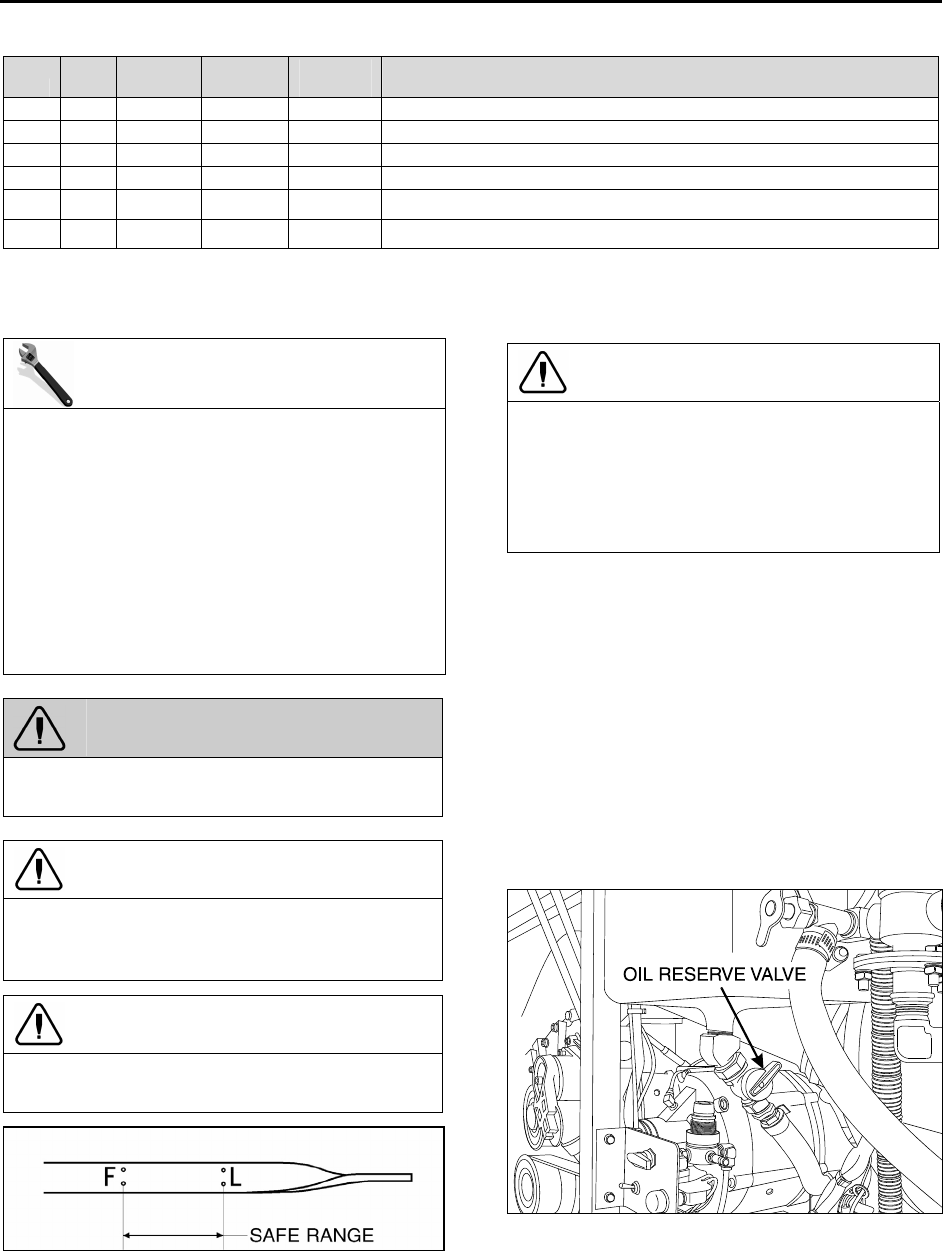
Section 01: ENGINE
PA1561 39
SPN FMI PID/SID
PID/SID
ID
FLASH
CODE FAULT DESCRIPTION
4227 5 SID 53 1324 Electrostatic Oil Separator Circuit Failed Open
4227 4 SID 155 1615 Oil Separator Circuit Failed Low
4227 3 SID 155 1615 Oil Separator Circuit Failed High
4227 7 SID 155 1615 Oil Separator, Max. Duration Time Reached
4228 16 SID 147 1241 Smart Remote Actuator 5 (VGT), Temperature Fault
4228 15 SID 147 1241 Smart Remote Actuator 5 (VGT), Temperature Warning
2.12 ENGINE OIL LEVEL
MAINTENANCE
Check the oil level daily with the engine
stopped. If the engine has just been stopped
and is warm, wait at least 10 minutes to allow
the oil to drain back to the oil pan before
checking. Wipe the dipstick clean then check
oil level. The level should always be within the
safe range on the dipstick (Fig. 17). Add the
proper grade of oil to maintain the correct level
on the dipstick. All diesel engines are
designed to consume some oil, so a periodic
addition of oil is normal.
WARNING
Touching a hot engine can cause serious
burns.
CAUTION
Do not overfill. Oil may be blown out through
the crankcase breather if the crankcase is
overfilled.
CAUTION
Clean end of tube before removing the dipstick
to prevent oil contamination.
FIGURE 17: ENGINE OIL LEVEL DIPSTICK 01027
CAUTION
If the oil level is constantly above normal and
excess lube oil has not been added to the
crankcase, consult with an authorized Detroit
Diesel service outlet for the cause. Fuel or
coolant dilution of lube oil can result in serious
engine damage.
The vehicle is provided with an oil reserve tank
with a capacity of 2.2 US gallons (8,3 liters).
This reserve tank is connected to the crankcase
by a hose with a shutoff valve, allowing oil to be
added to crankcase. To adjust oil level, open the
oil reserve tank shutoff valve and allow oil to
discharge into the engine until the «Full» mark on
the dipstick is reached then close the valve.
Check oil reserve tank level and pour oil in the
reserve tank if necessary (Fig. 18). Comparison
of oil levels in sight gauge, before and after
adding oil to crankcase, shows approximately
how much oil has been added.
FIGURE 18: OIL RESERVE TANK 01050
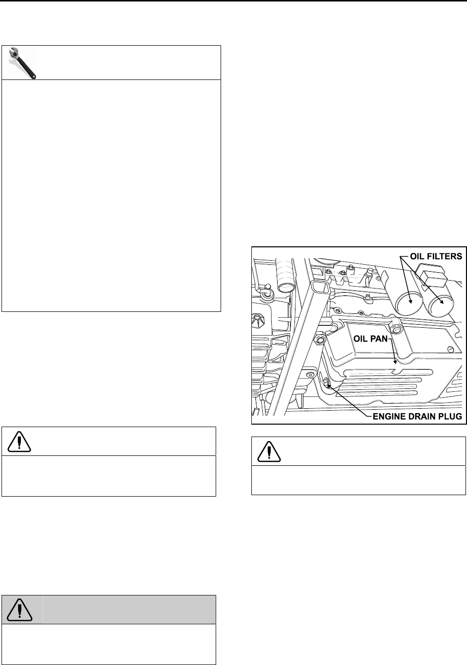
Section 01: ENGINE
PA1561 40
2.13 ENGINE OIL AND FILTER CHANGE
MAINTENANCE
Both the engine oil and filter should be
changed according to the following maximum
interval (based on an oil analysis program).
Short Haul: 15,000 miles (24,000km) or once
a year, whichever comes first.
Long Haul: 30,000 miles (48,000km) or once
a year, whichever comes first.
Oil analysis program may be used to determine
whether this interval should be shorter, but
should not be used to lengthen the interval.
Short haul: 6,000 miles (10,000km) to 60,000
miles (100,000 km) annual.
Long haul: over 60,000 miles (100,000 km)
annual.
However, changes that are more frequent may
be required when the engine is subject to high
levels of contamination and/or overheating.
Change intervals may be decreased or gradually
increased with experience on specific lubricants
until the most practical service condition has
been established. Always refer to the lubricant
manufacturer’s recommendations (analysis of
drained oil can be helpful).
CAUTION
Do not use solvents to dilute the engine oil
when draining. Dilution of fresh oil can occur
which may be detrimental to the engine.
Change engine oil with the vehicle on a flat and
level surface and with the parking brake applied.
It is best to drain the oil when the engine is still
warm.
1. From under the vehicle, remove the engine
drain plug on the oil pan. Allow oil to drain
(Fig. 19).
WARNING
Hot engine oil can cause serious burns. Wear
coveralls with sleeves pulled down and gloves
to protect hands.
2. Reinstall the drain plug.
3. Remove the spin-on filter cartridge using a
1/2″ drive socket wrench and extension.
4. Dispose of the used oil and filter in an
environmentally responsible manner in
accordance with state and/or federal (EPA)
recommendations.
5. Clean the filter adapter with a clean rag.
6. Lightly coat the filter gasket (seal) with clean
engine oil.
7. Install the new filter on the adapter and
tighten manually until the gasket touches the
mounting adapter head. Tighten full-flow
filters an additional two-thirds of a turn
manually. Then, manually tighten bypass
filter one full turn.
FIGURE 19: UNDER VEHICLE VIEW 01029
CAUTION
Overtightening may distort or crack the filter
adapter.
8. Remove the engine-oil filler cap and pour oil
in the engine until it reaches the «FULL» mark
on the dipstick (Fig. 17).
9. Start and run the engine for a short period
and check for leaks. After any leaks have
been corrected, stop the engine long enough
for oil from various parts of the engine to
drain back to the crankcase (approximately
20 minutes).
10. Add oil as required to bring the level within
the safe range on the dipstick.

Section 01: ENGINE
PA1561 41
MAINTENANCE
Engine oil temperature should be checked
every 25,000 miles (40 000 km) to determine
oil cooler efficiency. This check should be
made by inserting a steel jacketed
thermometer in the dipstick opening,
immediately after stopping a hot, loaded
engine. If the oil temperature exceeds the
coolant temperature by more than 60 °F (33
°C), the oil cooler may be clogged.
For detailed oil specifications, refer to
DETROIT DIESEL SERIES 60 2007 ON-
HIGHWAY SERVICE MANUAL 6SE2007
under heading «Lubricating Oil for Detroit
Diesel Engines».
2.14 RECOMMENDED ENGINE OIL TYPE
To provide maximum engine life, lubricants shall
meet the following specifications: SAE Viscosity
Grade: 15W-40 API Classification: CJ-4.
CAUTION
Low ash oil formulation designated API CJ-4
is required in EPA-07 engines.
CJ-4 contains less than 1% ash which is the
key to achieving maximum diesel particulate
filter cleaning intervals. Use of high ash
engine oils will reduce the cleaning interval on
the Diesel Particulate Filter (DPF). DPF
regenerates the combustible soot, but the ash
(a product of the oil lubricant package) slowly
accumulates in the channels of the DPF.
NOTE
Monograde oils should not be used in these
engines regardless of API Service
Classification.
NOTE
The use of supplemental oil additives is
discouraged from use in Detroit Diesel
Engines.
Synthetic oils: Synthetic oils may be used in
Detroit Diesel engines provided they are API-
licensed and meet the performance and
chemical requirements of non-synthetic oils
outlined previously. Synthetic oils do not permit
extension of recommended oil drain intervals.
NOTE
COLD WEATHER STARTING
The proper selection of the engine oil grade
will ease cold weather starting (refer to the
lubrication and servicing schedule for the
engine oil grade recommendation). Other
practical considerations, such as the use of
batteries, cables and connectors of adequate
size, proper setting of voltage regulator, ether
starting aid, oil and coolant heater systems,
and proper fuel selection will ease cold
weather starting.
2.15 POWER PLANT ASSEMBLY REMOVAL
To access the engine or engine-related
components, the vehicle power plant assembly
must be removed as a whole unit by means of a
slide-out cradle. The power plant assembly
includes the engine, transmission (including
retarder if so equipped), air compressor,
alternator and transmission oil cooler.
Remove the power plant assembly as follows:
CAUTION
Tag hoses and cables for identification before
disconnecting in order to facilitate
reinstallation. Plug all openings to prevent dirt
from entering the system.
NOTE
The MCM is non-serviceable. If found
defective, replace as a unit.
1. Disconnect the battery cables from the
batteries. With the electrical circuit disrupted,
accidental contact with the starter button will
not produce an engine start. In addition, the
Electronic Unit Injectors (EUI) will be
disabled, preventing any fuel delivery to the
injector tips.
WARNING
Due to the heavy load of the rear bumper
assembly, it must be adequately supported
before attempting to remove it.
2. Remove the rear bumper assembly from the
vehicle. Refer to Section 18 BODY, under
«Rear Bumper Removal And Installation».

Section 01: ENGINE
PA1561 42
3. Drain the engine cooling system. Refer to
Section 05 COOLING under «Draining Cooling
System».
FIGURE 20: ENGINE COMPARTMENT 01044
4. Locate the A/C compressor drive belt
tensioner control valve (Fig. 23). Turn handle
clockwise in order to release pressure in belt-
tensioner air bellows and loosen belts.
Remove the belt.
5. Release all pressure from the air system.
Refer to Section 12 BRAKES & AIR
SYSTEM for instructions.
6. Disconnect and remove the engine-air
intake duct mounted between air cleaner
housing and turbocharger inlet.
CAUTION
To avoid damage to turbocharger, cover the
turbocharger inlet opening to prevent foreign
material from entering.
7. Disconnect and remove the air intake duct
mounted between the turbocharger outlet
and the charge air cooler inlet.
8. Disconnect and remove the air intake duct
mounted between the charge air cooler outlet
and the engine intake.
9. Disconnect and remove section of coolant
pipe assembly mounted between the radiator
outlet and the water pump inlet.
10. Disconnect and remove a section of coolant
pipe assembly mounted between the
thermostat housing and the radiator inlet.
11. Disconnect the coolant delivery hose
mounted between the coolant surge tank and
the water pump.
12. Disconnect two vent hoses from the
thermostat housing and from the coolant pipe
assembly.
13. Disconnect the fan-clutch electrical
connector.
14. Disconnect the radiator fan drive shaft.
15. Disconnect the small heater hose located on
the cylinder head at the back of the engine.
16. Disconnect and remove the exhaust pipe
mounted between the turbocharger outlet
and the exhaust bellows. If necessary, refer
to Section 04 EXHAUST SYSTEM under “AFT
Removal and Installation».
CAUTION
To avoid damage to turbocharger, cover the
turbocharger outlet opening to prevent foreign
material from entering.
17. Disconnect the block heater connector
above the power steering pump.
18. Disconnect the steel-braided airline from the
A/C compressor air bellows.
19. Disconnect the oil delivery hose from the
valve located at the reserve tank drain.
20. Remove the power steering pump, leaving
the supply and discharge hoses connected t
it.
21. Close engine fuel supply shutoff valve on
primary fuel filter. Disconnect the fuel line
connected to inlet port. On vehicles equipped
with the optional water-separator-fuel-filter,
disconnect the connector and remove cable
ties from cradle.
22. Disconnect fuel return line from bulkhead
fixed on engine cylinder head end.
23. Disconnect the air compressor discharge
airline.
24. Disconnect the coolant hose to the sump
tank heater system.
25. Disconnect positive (+) cable (red terminal)
from starter motor solenoid.
26. Disconnect starter motor ground cables from
rear subframe ground-stud located close to
the starter motor.
27. Disconnect VIH (vehicle interface harness)
main connectors from MCM and VSS
(vehicle speed sensor).
28. On vehicles equipped with an automatic
transmission provided with a hydraulic output
retarder, disconnect steel-braided airline from

Section 01: ENGINE
PA1561 43
pressure regulator output. The pressure
regulator is mounted in the upper section of
engine compartment backwall and is
accessible through the engine compartment
R.H. side door.
29. On vehicles equipped with an electrically
operated cold-starting aid, disconnect the
delivery hose from the starting-aid cylinder
solenoid valve. Remove cable ties securing
hoses.
30. Disconnect the transmission harness
(Allison: 2 main connectors, 1 connector to
the retarder accumulator solenoid) (ZF
transmission: 3 connectors).
31. From under the vehicle, disconnect the
propeller shaft as detailed in Section 09,
under heading «Propeller Shaft Removal».
32. Inspect the power plant assembly to ensure
that nothing will interfere when sliding out the
cradle. Check for connections or hoses not
mentioned in this list as some vehicles are
equipped with special or aftermarket
components.
33. Remove the six retaining bolts, washers and
nuts securing the power plant cradle to the
vehicle rear subframe (Fig. 23).
NOTE
Check if any spacer(s) have been installed
between power plant cradle and vehicle rear
subframe, and if so, note position of each
washer for reinstallation purposes.
34. Using a forklift, with a minimum capacity of
4,000 lbs (1 800 kg), slightly raise the power
plant cradle.
35. Pull engine out slowly from the engine
compartment. Make sure all lines, wiring and
accessories are disconnected and are not
tangled.
CAUTION
Due to the minimum clearance between the
power plant equipment and the top of the
engine compartment, extreme care should be
used to raise the power plant cradle, just
enough to free the cradle. Clearance between
power plant cradle and mounting rail should
range between 1/4″ and 1/2″ (6-12 mm).
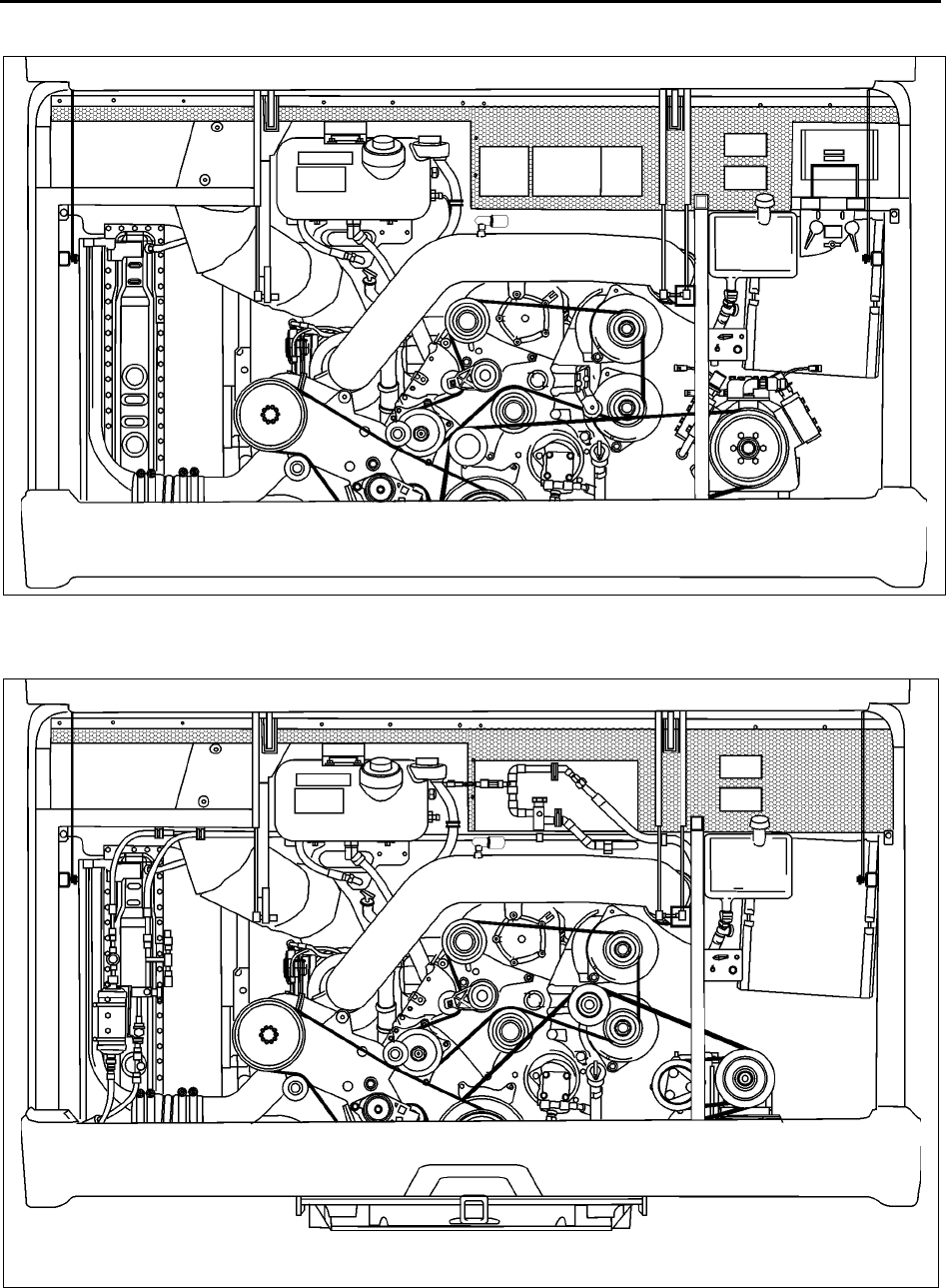
Section 01: ENGINE
PA1561 44
FIGURE 21: ENGINE COMPARTMENT H3 COACHES (TYPICAL) 01177
FIGURE 22: ENGINE COMPARTMENT VIP (TYPICAL) 01178
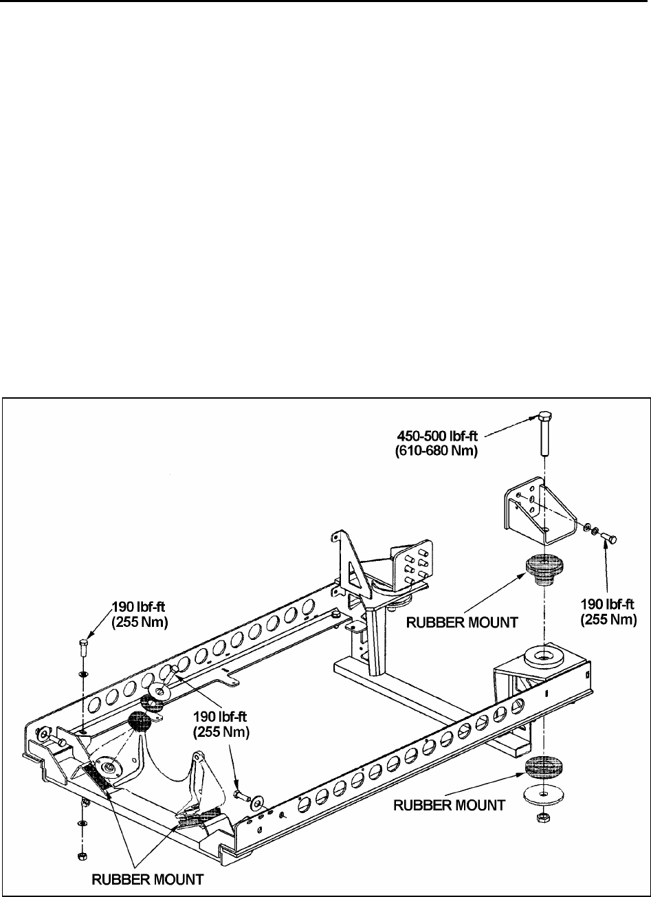
Section 01: ENGINE
PA1561 45
2.16 POWER PLANT ASSY. INSTALLATION
To install a power plant assembly, follow the
same procedure as in «Power Plant Assembly
Removal» except in reverse order, then proceed
with the following:
5. Torque the power plant cradle mounting
bolts to 190 lbf-ft (255 Nm).
6. If fan drive has been removed, reinstall and
align as per Section 05 COOLING SYSTEM,
under «Fan Drive Alignment».
7. Refill cooling system with saved fluid (refer
to Section 05 COOLANT SYSTEM).
8. Once engine fuel system has been drained,
it will aid restarting if fuel filters are filled with
fuel oil (refer to Section 03 FUEL SYSTEM).
9. Start engine for a visual check. Check fuel,
oil, cooling, pneumatic and hydraulic system
connections for leakage. Test operation of
engine controls and accessories.
2.17 JAKE BRAKE
Refer to both «The Jake Brake Troubleshooting
and Maintenance Manual» and «Installation
Manual for Model 797 Engine Brakes» for
troubleshooting and installation procedures.
They are annexed at the end of this section.
2.18 ENGINE MOUNTS
The power plant assembly on a vehicle powered
with a series 60 engine is mounted to the cradle
by means of rubber mounts.
Two rubber mounts are used at the front of the
engine while two others are mounted on each
side of the flywheel housing (Fig. 23).
It is recommended that new rubber mounts be
installed at each major overhaul.
FIGURE 23: POWER PLANT CRADLE INSTALLATION 01107

Section 01: ENGINE
PA1561 46
3. ELECTRONIC FOOT PEDAL ASSEMBLY
(EFPA) & THROTTLE POSITION SENSOR
The Electronic Foot Pedal Assembly (EFPA)
connects the accelerator pedal to a Throttle
Position Sensor (TPS). The (TPS) is a device,
which sends an electrical signal to the Motor
Control Module (MCM). The TPS varies in
voltage depending on how far the pedal is
depressed. The system is installed in the space
normally occupied by a mechanical foot pedal.
The (EFPA) has maximum and minimum stops
that are built into the unit during manufacturing
(Fig. 24). The (TPS) converts the operator’s foot
pedal input into a signal for the MCM.
When installed by the equipment manufacturer,
the TPS should not require adjustment. If the
TPS is suspected of being misadjusted, confirm
that the sensor is installed in accordance with
the manufacturer’s specifications. It is
recommended that the idle count be at 50 or
higher with a full throttle count of up to 200.
The TPS is self-calibrating and therefore has no
optimum closed throttle or wide open throttle
count value. If the counts are within the 50 to
200 range, the sensor is properly set.
FIGURE 24: ELECTRONIC FOOT PEDAL ASSEMBLY 03035
Monitor the (TPS) at the controls as you move it
through its full stroke. Be sure there is no
misalignment or obstruction preventing the
smooth movement of the TPS through the full
stroke. Using a diagnostic data reader, check
that the idle and full throttle position counts do
not fall within the error zones. The error zones
occur when the idle position is less than 14
counts, or when the full throttle position is more
than 233 counts. Should these conditions occur,
the CPC will signal diagnostic codes of 21-12 for
idle error and 21-23 for wide-open throttle error.

Section 01: ENGINE
PA1561 47
4. ENGINE TROUBLESHOOTING GUIDE
is the
engine
starting ?
plug the Diagnostics Data
Reader DDR into the receptacle
or momentarily depress the
stop engine «OVERRIDE»
switch to activate the DDEC
self-diagnostic system
yes
no
does the
engine
rotate ?
no
yes
does the red
«Stop Engine»
indicator
illuminate and
go off after 5
sec. ?
yes
no
go to
step 2
go to
step 3
with diagnostic code in
hand, contact your
Detroit Diesel service
center
START
see
note 1
faulty 12-volt-system power supply,
probable causes :
— battery cables improperly connected
— fuse blown
— faulty battery equalizer
— activate the DDEC self-diagnostic system
and contact your Detroit Diesel service
center
engine does not rotate
what is the
voltage reading
on 24-volt-
system
dashboard
indicator ?
is the shift
selector to
neutral «N»
position ?
higher than
24 volts
lower than
24 volts
yes
no
faulty 24-volt-system power supply
or low battery voltage. Contact
Prévost Action Services
there may be a problem
with the starter or starter
circuit. Contact Detroit
Diesel or Prévost Action
Service
step 2
place the shift selector to
neutral «N» position and start
the engine
is the rear start
selector to
«NORMAL»
position?
no
Set the rear start
selector to «NORMAL»
yes

Section 01: ENGINE
PA1561 48
is there motor
exhaust fumes
?
yes
plug the Diagnostics Data
Reader DDR into the
receptacle or momentarily
depress the stop engine
«OVERRIDE» switch to
activate the DDEC self-
diagnostic system
note 1
REFERENCES
-Operator’s Manual chap. 3,4 & 8
-Detroit Diesel pamphlet «DDEC
III/IV diagnostic codes and MPSI
reader functions»
-8V92 series engine, switch is
located in service compartment
no
what is the
voltage
reading on the
12-volt-system
indicator ?
higher than
10 volts
lower than
10 volts
with diagnostic code in
hand, contact your
Detroit Diesel service
center
probable causes :
— 12-volt-system batteries low
— faulty battery equalizer
— 12-volt-system batteries
improperly connected
— 12-volt-system battery master
switch to «OFF» position (H3-40)
probable cause :
-no fuel
-check the 2 breakers on the injector
feeding system.
Contact Detroit Diesel
or Prévost Action Service
step 3
see
note 2
note 2
see the analog voltage indicator
on the dashboard or consult the
MCD «Message Center Display»
on the telltale panel. See the
Operator’s Manual chap. 4 for
more details
see
note 1
01089

Section 01: ENGINE
PA1561 49
5. SPECIFICATIONS
5.1 SERIES 60 ENGINE
Make …………………………………………………………………………………………………………..…………… Detroit Diesel
Type …………………………………………………………………………………………………Diesel four cycle/in-line engine
Description ………………………………………………………………………………………… Turbo/Air to air charge cooled
No. of cylinders …………………………………………………………………………………………………………………………… 6
Operating range ………………………………………………………………………………………………….….1200-2100 RPM
Maximum RPM……………………………………………………………………………………………………..……………….. 2100
CAUTION
To avoid possible engine damage, do not use single grade (Monograde) lubricants in Detroit Diesel
four-cycle Series 60 engines, regardless of API classification.
Detroit Diesel Series 60 engine ratings
Series 60 engine ratings used in Prevost Car Models are listed in the following tables. The standard
engine ratings are written in bold, customer may easily switch from one rating to another within the same
table by having the DDEC VI system reprogrammed.
Coach Engine (14.0L)
425 HP @1800 rpm; 1450 lb-ft @1200 rpm
445 HP @1800 rpm; 1450 lb-ft @1200 rpm
Motorhome (14.0L)
470 HP @1800 rpm; 1650 lb-ft @1200 rpm
515 HP @1800 rpm; 1650 lb-ft @1200 rpm
Entertainer Engine (14.0L)
455 HP @1800 rpm; 1550 lb-ft @1200 rpm
490 HP @1800 rpm; 1550 lb-ft @1200 rpm
515 HP @1800 rpm; 1550 lb-ft @1200 rpm
Capacity
Oil reserve tank ………………………………………………………………………………………………….. 8.4 US qts (8.0 L)
Engine oil level quantity
Oil Pan Capacity; Low Limit ………………………………………………………………………………….26 quarts/25 liters
Oil Pan Capacity; High Limit …………………………………………………………………………………32 quarts/30 liters
Total Engine Oil Capacity with Filters …………………………………………………………………….38 quarts/36 liters
Lubricating oil filter elements
Make……………………………………………………………………………………… AC Rochester Div. GMC # 25014505
Make…………………………………………………………………………………………………………….. A/C Filter # PF-2100
Type ……………………………………………………………………………………………………………………………… Full Flow
Prevost number…………………………………………………………………………………………………..……………. 510458

Section 01: ENGINE
PA1561 50
Torque specification
Engine oil filter…………………………………………………………………… Tighten 2/3 of a turn after gasket contact
Filters
Engine Air Cleaner Filter
Make …………………………………………………………………………………………………………….. Nelson # 70337-N
Prevost number ………………………………………………………………………………………………….…………. 530197
Engine Coolant Filter/Conditioner
Make …………………………………………………………………………………Nalco Chemical Company # DDF3000
Make …………………………………………………………………………………………………..Detroit Diesel # 23507545
Prevost number…………………………………………………………………………………………………..…………. 550630
NOTE
For primary and secondary fuel filters, refer to Specifications in section 03.
5.2 VOLVO D13 ENGINE
Make …………………………………………………………………………………………………………..……….Volvo Powertrain
Type ……………………………………………………………………………………………………………………..Diesel four cycle
Description ………………………………………………………………………………………… Turbo/Air to air charge cooled
No. of cylinders ………………………………………………………………………………………………………….12.8 L inline 6
Recommended cruise speed range ………………………………………………………………………….1300-1500 RPM
Maximum RPM……………………………………………………………………………………………………..……………….. 2100
Engine oil level quantity
Oil Pan Capacity; Low Limit ………………………………………………………………………………….25 quarts/24 liters
Oil Pan Capacity; High Limit …………………………………………………………………………………34 quarts/32 liters
Total Engine Oil Capacity with Filters ………………………………………………………………….45 quarts/42.5 liters
Lubricating oil filter elements
Prevost number………………………………………………………………………………………………… 478736 (Full Flow)
Prevost number…………………………………………………………………………………………………..510938 (By-pass)
Torque specification
Engine oil filter…………………………………………………………………… Tighten 3/4 to 1 turn after gasket contact
Filters
Engine Air Cleaner Filter
Prevost number ………………………………………………………………………………………………….…………. 530197
Engine Coolant Filter
Make ………………………………………………………………………………………………………………………………. Volvo
Number ………………………………………………………………………………………………………….…………. 20458771

Section 01: ENGINE
PA1561 51
NOTE
For primary and secondary fuel filters, refer to Specifications in section 03.
On this page you can free download workshop repair manuals PDF for Volvo trucks, and also fault codes PDF and Wiring Diagrams.
|
Title |
File Size |
Download Links |
|
Volvo C 303 Owner’s Manual [PDF] |
4Mb |
Download |
|
Volvo driver information display manual [PDF] |
772kb |
Download |
|
Volvo FM, FH, NH, FL, NL Service Manual — Lubrication service and oil |
1.9Mb |
Download |
|
Volvo truck Oil and Filter Service Scheduale [PDF] |
1.1Mb |
Download |
|
Volvo Truck Quality Manual [PDF] |
2.4Mb |
Download |
|
Volvo Trucks Service Bulletin — Transmission [PDF] |
7.2Mb |
Download |
|
Volvo TSI Vehicle Management System (VECTRO II, ECU) Service Manual |
4.5Mb |
Download |
|
Title |
File Size |
Download Links |
|
Volvo Cab Exterior Catalog [PDF] |
808.5kb |
Download |
|
Volvo Catalog Spare parts for trucks [PDF] |
2.5Mb |
Download |
|
Volvo Replacement Parts Catalog — Climate [PDF] |
248.2kb |
Download |
|
Volvo Replacement Parts Catalog 2012 [PDF] |
4.3Mb |
Download |
|
Volvo Truck / Bus Replacement Spare Parts Catalog PDF [PDF] |
7.7Mb |
Download |
|
VolvoCab Interior Catalog [PDF] |
1.3Mb |
Download |
![]()
Volvo driver information display manual
Volvo driver information display manual.
Adobe Acrobat Document
767.0 KB
![]()
Volvo Instrument Cluster Control Module (MID 140) Diagnostic Trouble Code (DTC), Guide
Volvo Instrument Cluster Control Module
Adobe Acrobat Document
439.4 KB
![]()
Volvo Engine D12A Fault Codes PDF
Volvo Engine D12A Fault Codes PDF.pdf
Adobe Acrobat Document
1’021.7 KB
![]()
Volvo L150F, L180F, L220F Recycling Manual
Volvo L150F, L180F, L220F Recycling Manu
Adobe Acrobat Document
2.1 MB
![]()
VOLVO 240 Engines d20 d24 repairs manual
VOLVO 240 Engines d20 d24 repairs manual
Adobe Acrobat Document
17.2 MB
![]()
Volvo FM, FH, NH, FL, NL Service Manual — Lubrication service and oil changes
Volvo FM, FH, NH, FL, NL Service Manual
Adobe Acrobat Document
2.0 MB
![]()
Volvo Maintenance and Engine — Operator’s Manual
Volvo Maintenance and Engine — Operator’
Adobe Acrobat Document
1.4 MB
![]()
Volvo L150F/L180F/L220F Recycling Manual
Volvo Tractor_Manual_L150F__L220F.pdf
Adobe Acrobat Document
2.1 MB
![]()
Volvo trucks Operator’s Manual: Maintenance and Engines
Volvo_Truck_Owners_Operators_M.pdf
Adobe Acrobat Document
1.4 MB
![]()
Volvo D12, D12A and D12B engines Workshop Manual PDF
Volvo D12, D12A and D12B engines Worksho
Adobe Acrobat Document
17.6 MB
![]()
Volvo Tractor L60F/L120F Recycling Manual
Volvo Tractor Manual_L60F__L120F.pdf
Adobe Acrobat Document
2.4 MB
![]()
Volvo Truck Fault codes
Volvo Truck Fault codes.rar
compressed file archive
790.6 KB
![]()
Volvo VHD 2,VN,VT Service Manual
Volvo VHD 2,VN,VT Manual.pdf
Adobe Acrobat Document
702.1 KB
![]()
Vovlo TAD650VE, TAD660VE, TAD734GE, TAD750VE, TAD760VE Workshop Manual
Vovlo TAD650VE, TAD660VE, TAD734GE, TAD7
Adobe Acrobat Document
2.3 MB
|
Title |
File Size |
Download Links |
|
Volvo A35 / A40D [PDF] |
458.4kb |
Download |
|
Volvo A35e Fs Articulated Dump Truck Workshop Manual [PDF] |
2.1Mb |
Download |
|
Volvo A35E, A35E FS, A40E, A40E FS Operator’s Manual [PDF] |
7.8Mb |
Download |
|
Volvo A40D Maintenance Manual [PDF] |
289.1kb |
Download |
|
Volvo A60H Maintenance Manual [PDF] |
7.1Mb |
Download |
|
Title |
File Size |
Download Links |
|
Volvo EC160B, 180B, 210B, 240B, 290B, 360B, 460B Service Manual |
11.7Mb |
Download |
|
VOLVO L120E Electrical Schematic Diagram [PDF] |
824.7kb |
Download |
|
Volvo Semi Truck Wiring Diagram [JPG] |
114.4kb |
Download |
![]()
Volvo Truck FH12, FH16 Electrical Wiring Diagrams
Volvo Truck FH12, FH16 Electrical Wiring Diagrams
Volvo Truck FH12, FH16 EWD.rar
compressed file archive
3.1 MB
![]()
Volvo FH12/FH16 Service Manual: Electrical Wiring Diagrams
Volvo FH12/FH16 Service Manual: Electrical Wiring Diagrams
Volvo_FH12_FH16 Manual.pdf
Adobe Acrobat Document
3.6 MB
![]()
Volvo FH12/FH16/RHD Wiring Diagrams
Volvo FH12 FH16 RHD Wiring Diagramc Wiri
Adobe Acrobat Document
3.1 MB
![]()
Volvo-FH-12(D12A-380) wiring diagrams
Volvo-FH-12(D12A-380) wiring diagrams.ra
compressed file archive
2.0 MB
![]()
VOLVO L120E Electrical Schematic Diagram
VOLVO L120E Electrical Schematic Diagram
Adobe Acrobat Document
955.0 KB
![]()
Volvo FH12 Geartronic Wiring diagram
Volvo FH12 Geartronic Wiring diagram.pdf
Adobe Acrobat Document
13.5 MB
Volvo D12A Fault Codes
Volvo driver information display manual
Volvo Instrument Cluster Control Module (MID 140) Diagnostic Trouble Code (DTC), Guide
Volvo L150F, L180F, L220F Recycling Manual
Volvo Maintenance and Engine — Operator’s Manual
Volvo Semi Truck Wiring Diagram
Volvo Tractor Manual_L60F__L120F
Volvo Tractor_Manual_L150F__L220F
Volvo Truck Fault codes
Volvo Truck FH12, FH16 EWD
Volvo VHD 2,VN,VT Manual
Volvo VN VHD Trucks Service & Repair Manual From Aug 1996-Nov 2002
Volvo_FH12_FH16 Manual
Volvo_Truck_Owners_Operators_M
Volvo-FH-12(D12A-380) wiring diagrams
|
Title |
File Size |
Download Links |
|
Volvo AQ125,145 Engine Unit Workshop Manual [PDF] |
5.3Mb |
Download |
|
Volvo BW55, AW55, AW70, AW71 Service and Repair Manual [PDF] |
10.5Mb |
Download |
|
Volvo D11H, D11H, D13H, D16H Engines Operator’s Manual [PDF] |
4.5Mb |
Download |
|
Volvo D12, D12A and D12B engines Workshop Manual PDF [PDF] |
17.8Mb |
Download |
|
Volvo D12, D12A, D12B, D12C Service Manual [PDF] |
668.5kb |
Download |
|
Volvo D13 Engine Service Manual [PDF] |
1.9Mb |
Download |
|
Volvo D13F Engine Workshop Manual [PDF] |
4.1Mb |
Download |
|
Volvo D13F Engines Fuel System, Design and Function Service Manual |
296.2kb |
Download |
|
Volvo D7, D12 Engines Service Manual [PDF] |
1.4Mb |
Download |
|
Volvo D7E B7RLE Manual [PDF] |
4Mb |
Download |
|
Volvo Engine D 20, D 24 Service and Repair Manual [PDF] |
16.3Mb |
Download |
|
Volvo Maintenance and Engine — Operator’s Manual [PDF] |
1.4Mb |
Download |
|
Vovlo TAD650VE, TAD660VE, TAD734GE, TAD750VE, TAD760VE Workshop |
2.3Mb |
Download |
Volvo Trucks Corporation is a Swedish automotive company, one of the world leaders in the production of heavy trucks. Belongs to the second largest truck manufacturer in the
world «Volvo Group».
Volvo Trucks in 2001 acquired a controlling package of Renault’s cargo division (RVI), which in 2002 became part of Renault Trucks. The president and chairman of the board of
directors is Leif Johansson. The post of the chairman of the board is occupied by the former head of Renault — Louis Schweitzer.
The company was founded in 1916 by Assar Gabrielsson (Swede Assar Gabrielsson) and Gustaf Larson (Swede Gustaf Larson) as a subsidiary of the well-known bearing manufacturer SKF. In 1927, the
first production car leaves the factory gate. Already in 1935 Volvo gained complete independence from SKF.
The first truck appeared at the beginning of 1928 — it was LV series 1, which had instant success, and 500 units were sold until the summer. It had a 2.0 liter engine with 4 cylinders, a capacity
of 28 hp. (21 kW).
Volvo produces mainly (95%) heavy commercial vehicles (in the class of over 16 tons). In terms of production volumes, Volvo Truck Corporation ranks second in the world market. In 2006, Volvo
Trucks sold 105519 units of trucks.
Volvo trucks are positioned by the manufacturer as safe and comfortable.
The global international corporation Volvo Trucks Corporation includes design and manufacturing centers located in Sweden, Belgium, Brazil and the USA, as well as a large number of assembly
enterprises around the world, some of which are represented by the corporation as a co-founder, together with local industrial groups, in Others are directly owned by the Volvo Group.
Volvo Trucks, in addition to the same brand, is also the owner of such brands of truck manufacturers as Renault Trucks (Renault Trucks), Mack Truck (American brand) and Nissan Diesel (now — UD Trucks).
Volvo Trucks also was once the co-owner of the well-known truck manufacturer Scania, but in accordance with the decision of the antimonopoly committee of the European Union sold its share of the
company’s shares on the market.
Volvo Trucks has representative offices and service centers in more than 130 countries. Over 1000 local dealerships in different parts of the world and 1800 technical centers provide sales and
maintenance of trucks.
Almost half of the total sales of its new equipment Volvo Trucks in Western Europe, more than a third — in America. Eastern Europe accounts for 6% of gross sales, but this market is currently the
fastest growing for Volvo Trucks. In Russia in 2006, 2436 units of Volvo Trucks’ heavy-duty vehicles were sold.
In the structure of production of Volvo trucks Volvo FH owns the largest share, in 2006 the manufacturer sold over 40 thousand trucks of this series.
It’s easier than the FH series in the current lineup — Volvo’s FM series trucks, which are designed for short and medium haulage. Ravozovye
trucks — this Volvo FL. These trucks mainly serve for quick deliveries in the city and in the suburbs, the removal of domestic waste and the provision of other utilities.
Despite the fact that Volvo sold its Volvo Car division, the VOLVO group includes the following units:
- Volvo Trucks (manufactures lorries)
- Mack Trucks
- Renault Trucks
- UD Trucks
- Volvo Bussar
- Volvo Construction Equipment
- Volvo Penta
- Volvo Aero
- Volvo Financial Services
In 2008, Volvo Trucks sold 105,952 trucks