Руководство на английском языке по техническому обслуживанию и ремонту двигателей Hino моделей W06D-TI и W06D-TI-II.
- Автор: —
- Издательство: Hino Motors
- Год издания: —
- Страниц: 236
- Формат: PDF
- Размер: 3,4 Mb
Руководство на английском языке по техническому обслуживанию и ремонту двигателей Hino моделей W04C-T, W04C-TI, W04D.
- Автор: —
- Издательство: Hino Motors
- Год издания: —
- Страниц: 216
- Формат: PDF
- Размер: 5,2 Mb
Руководство на английском языке по техническому обслуживанию и ремонту двигателей Hino модели W04D.
- Автор: —
- Издательство: Hino Motors
- Год издания: —
- Страниц: 205
- Формат: PDF
- Размер: 4,4 Mb
Руководство по техническому обслуживанию и ремонту двигателей Hino моделей H06, H06C-T, H06C, H07C-T, H07D, EH700, EH700-TI, EP100-TI.
- Автор: —
- Издательство: Легион-Автодата
- Год издания: —
- Страниц: 144
- Формат: —
- Размер: —
Руководство по техническому обслуживанию и ремонту двигателей Hino моделей J08C-TP, J08C-TR, J05C, J05C-TD, J05D, J05E-TE, J05E-TC, J05E-TD, S05C, S05C-B, S05C-TA, S05C-TB, S05D.
- Автор: —
- Издательство: Легион-Автодата
- Год издания: —
- Страниц: 190
- Формат: —
- Размер: —
Руководство по техническому обслуживанию и ремонту двигателей Hino моделей J05C, S05C, S05C-B, S05C-TA, S05C-TB, S05D.
- Автор: —
- Издательство: Легион-Автодата
- Год издания: —
- Страниц: 120
- Формат: —
- Размер: —
Руководство по техническому обслуживанию и ремонту двигателей Hino моделей W04 и W06.
- Автор: —
- Издательство: Легион-Автодата
- Год издания: —
- Страниц: 134
- Формат: —
- Размер: —

![]()
Diesel Injection Pump
SERVICE MANUAL
Common Rail System for HINO Dutro / TOYOTA Dyna N04C-T# Type Engine
OPERATION
November, 2003
00400058E
|
TABLE OF CONTENTS |
|||
|
1. |
Product Application List . . . . . . . . . . . . . . . . . . . . . . . . . . . . . . . . . . . . . . . . . . . . . . . . . . . . . . . . . . . . . . . . . . . . . . . . . . . . . . . . |
1 |
|
|
1-1. |
Vehicle Specifications . . . . . . . . . . . . . . . . . . . . . . . . . . . . . . . . . . . . . . . . . . . . . . . . . . . . . . . . . . . . . . . . . . . . . . . . . . . . . . |
1 |
|
|
1-2. |
Component Part Numbers . . . . . . . . . . . . . . . . . . . . . . . . . . . . . . . . . . . . . . . . . . . . . . . . . . . . . . . . . . . . . . . . . . . . . . . . . . . |
1 |
|
|
2. |
Common Rail System Outline . . . . . . . . . . . . . . . . . . . . . . . . . . . . . . . . . . . . . . . . . . . . . . . . . . . . . . . . . . . . . . . . . . . . . . . . . . . . |
2 |
|
|
2-1. |
Background to Development . . . . . . . . . . . . . . . . . . . . . . . . . . . . . . . . . . . . . . . . . . . . . . . . . . . . . . . . . . . . . . . . . . . . . . . . |
2 |
|
|
2-2. |
System Characteristics . . . . . . . . . . . . . . . . . . . . . . . . . . . . . . . . . . . . . . . . . . . . . . . . . . . . . . . . . . . . . . . . . . . . . . . . . . . . . |
2 |
|
|
2-3. Comparison to The Conventional System . . . . . . . . . . . . . . . . . . . . . . . . . . . . . . . . . . . . . . . . . . . . . . . . . . . . . . . . . . . . . . |
3 |
||
|
3. |
Outline of TOYOTA / HINO Small Truck Common Rail System . . . . . . . . . . . . . . . . . . . . . . . . . . . . . . . . . . . . . . . . . . . . . . . . |
4 |
|
|
3-1. |
Main System Components . . . . . . . . . . . . . . . . . . . . . . . . . . . . . . . . . . . . . . . . . . . . . . . . . . . . . . . . . . . . . . . . . . . . . . . . . . |
4 |
|
|
3-2. Outline of Composition and Operation . . . . . . . . . . . . . . . . . . . . . . . . . . . . . . . . . . . . . . . . . . . . . . . . . . . . . . . . . . . . . . . . |
5 |
||
|
3-3. Fuel System and Control System . . . . . . . . . . . . . . . . . . . . . . . . . . . . . . . . . . . . . . . . . . . . . . . . . . . . . . . . . . . . . . . . . . . . . |
6 |
||
|
4. |
Description of Main Components . . . . . . . . . . . . . . . . . . . . . . . . . . . . . . . . . . . . . . . . . . . . . . . . . . . . . . . . . . . . . . . . . . . . . . . . . |
7 |
|
|
4-1. |
Supply Pump (HP3) . . . . . . . . . . . . . . . . . . . . . . . . . . . . . . . . . . . . . . . . . . . . . . . . . . . . . . . . . . . . . . . . . . . . . . . . . . . . . . . . |
7 |
|
|
4-2. |
Rail . . . . . . . . . . . . . . . . . . . . . . . . . . . . . . . . . . . . . . . . . . . . . . . . . . . . . . . . . . . . . . . . . . . . . . . . . . . . . . . . . . . . . . . . . . . . . |
14 |
|
|
4-3. |
Injector . . . . . . . . . . . . . . . . . . . . . . . . . . . . . . . . . . . . . . . . . . . . . . . . . . . . . . . . . . . . . . . . . . . . . . . . . . . . . . . . . . . . . . . . . |
16 |
|
|
4-4. Engine ECU (Electronic Control Unit) . . . . . . . . . . . . . . . . . . . . . . . . . . . . . . . . . . . . . . . . . . . . . . . . . . . . . . . . . . . . . . . . |
19 |
||
|
4-5. EDU (Electronic Driving Unit) . . . . . . . . . . . . . . . . . . . . . . . . . . . . . . . . . . . . . . . . . . . . . . . . . . . . . . . . . . . . . . . . . . . . . . . |
19 |
||
|
5. |
Description of Control System Components . . . . . . . . . . . . . . . . . . . . . . . . . . . . . . . . . . . . . . . . . . . . . . . . . . . . . . . . . . . . . . |
20 |
|
|
5-1. |
Block Diagram . . . . . . . . . . . . . . . . . . . . . . . . . . . . . . . . . . . . . . . . . . . . . . . . . . . . . . . . . . . . . . . . . . . . . . . . . . . . . . . . . . . |
20 |
|
|
5-2. |
Description of Sensors . . . . . . . . . . . . . . . . . . . . . . . . . . . . . . . . . . . . . . . . . . . . . . . . . . . . . . . . . . . . . . . . . . . . . . . . . . . . |
21 |
|
|
6. |
Various Types of Controls . . . . . . . . . . . . . . . . . . . . . . . . . . . . . . . . . . . . . . . . . . . . . . . . . . . . . . . . . . . . . . . . . . . . . . . . . . . . . . |
26 |
|
|
6-1. Common Rail System Outline . . . . . . . . . . . . . . . . . . . . . . . . . . . . . . . . . . . . . . . . . . . . . . . . . . . . . . . . . . . . . . . . . . . . . . . |
26 |
||
|
6-2. Fuel Injection Quantity Control . . . . . . . . . . . . . . . . . . . . . . . . . . . . . . . . . . . . . . . . . . . . . . . . . . . . . . . . . . . . . . . . . . . . . . |
27 |
||
|
6-3. Fuel Injection Timing Control . . . . . . . . . . . . . . . . . . . . . . . . . . . . . . . . . . . . . . . . . . . . . . . . . . . . . . . . . . . . . . . . . . . . . . . |
30 |
||
|
6-4. Fuel Injection Rate Control . . . . . . . . . . . . . . . . . . . . . . . . . . . . . . . . . . . . . . . . . . . . . . . . . . . . . . . . . . . . . . . . . . . . . . . . . |
31 |
||
|
6-5. Fuel Injection Pressure Control . . . . . . . . . . . . . . . . . . . . . . . . . . . . . . . . . . . . . . . . . . . . . . . . . . . . . . . . . . . . . . . . . . . . . |
31 |
||
|
7. |
Other (ECU Related) . . . . . . . . . . . . . . . . . . . . . . . . . . . . . . . . . . . . . . . . . . . . . . . . . . . . . . . . . . . . . . . . . . . . . . . . . . . . . . . . . . |
32 |
|
|
7-1. ECU External Wiring and Terminal Layout . . . . . . . . . . . . . . . . . . . . . . . . . . . . . . . . . . . . . . . . . . . . . . . . . . . . . . . . . . . . |
32 |
||
|
7-2. |
Diagnostic Trouble Code . . . . . . . . . . . . . . . . . . . . . . . . . . . . . . . . . . . . . . . . . . . . . . . . . . . . . . . . . . . . . . . . . . . . . . . . . . . |
38 |
|
1. |
Product Application List |
|||
|
1-1. |
Vehicle Specifications |
|||
|
Vehicle Name |
Engine Model |
Exhaust Volume |
||
|
HINO DUTRO / TOYOTA DYNA |
N04C-TF |
4.0L |
||
1-2. Component Part Numbers |
||||
|
Product Name |
HINO Part Number |
DENSO Part Number |
||
|
Supply Pump |
22730-1261B |
294000-0191 |
||
|
Rail |
22760-1170A |
095440-0490 |
||
|
Injector |
23910-1271A |
095000-5321 |
||
|
Engine ECU |
89660-37460 |
101758-6580 |
||
|
EDU |
89870-37030 |
101310-5391 |
||
|
APM (Accelerator Pedal Module) |
78100-37550 |
198800-3150 |
||
|
NE Sensor |
89411-1630A |
029600-1361 |
||
|
TDC Sensor |
89410-1570A |
949979-1310 |
||
|
Coolant Temperature Sensor |
83420-1250A |
071560-0110 |
||
|
AFM (Mass Airflow Meter) |
22204-21010 |
197400-2000 |
||
|
Intake Air Temperature Sensor |
89441-4310A |
071500-2490 |
||
|
Turbo Pressure Sensor |
89390-1080A |
079800-5890 |
||
|
EGR-V |
17350-1170A |
135000-7051 |
||
|
Exhaust Gas Temperature Sensor |
89441-37020 (IN) |
265600-0600 (IN) |
||
|
89441-37030 (OUT) |
265600-0530 (OUT) |
|||
-1-

2. Common Rail System Outline
2-1. Background to Development
•The common rail system was developed primarily to cope with exhaust gas regulations for diesel engines, and is a diesel injection control system with the following aims:
•To further improve fuel economy;
•To reduce noise;
•To achieve high power output.
2-2. System Characteristics
•The common rail system uses a type of accumulation chamber called a rail to store pressurized fuel, and injectors that contain electronically controlled solenoid valves to inject the pressurized fuel into the cylinders. Because the engine ECU controls the injection system (injection pressure, injection rate, and injection timing), the injection system is independent, and thus unaffected by the engine speed or load. This ensures a stable injection pressure at all times, particularly in the low engine speed range, and dramatically decreases the amount of black smoke ordinarily emitted by a diesel engine during start-up and acceleration. As a result, exhaust gas emissions are cleaner and reduced, and higher power output is achieved.
A.Injection Pressure Control
•Enables high-pressure injection even at low engine speeds.
•Optimizes control to minimize particulate matter and NOx emissions.
B.Injection Timing Control
•Enables finely tuned optimized control in accordance with driving conditions.
C.Injection Rate Control
•Pilot injection control injects a small amount of fuel before the main injection.
|
Common Rail System |
||||||||||
|
Injection Pressure Control |
Injection Timing Control |
Injection Rate Control |
||||||||
|
Optimization, High Pressurization |
Optimization |
Rate |
Pilot |
After-Injection |
||||||
|
Injection |
||||||||||
|
Post-Injection |
||||||||||
|
Injection Pressure |
Common Rail System |
Common Rail |
Injection |
Main |
||||||
|
System |
||||||||||
|
Injection |
||||||||||
|
Particulate |
||||||||||
|
NOx |
Crankshaft Angle |
|||||||||
|
Injection Quantity Control |
||||||||||
|
Conventional |
Conventional |
Cylinder Injection |
||||||||
|
Quantity Correction |
||||||||||
|
Pump |
TimingInjection |
|||||||||
|
Pump |
||||||||||
|
Speed |
Injection Pressure |
Speed |
Speed |
|||||||
|
1 |
3 |
4 |
2 |
|||||||
|
Q000518E |
||||||||||
|
-2- |
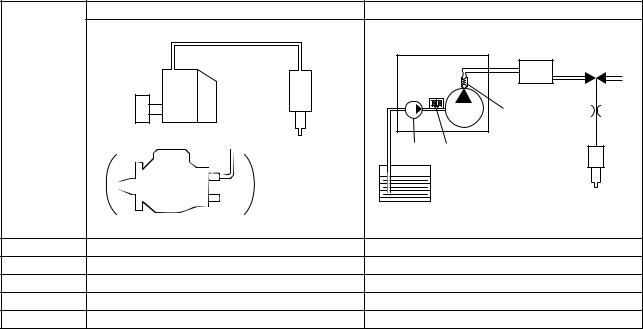
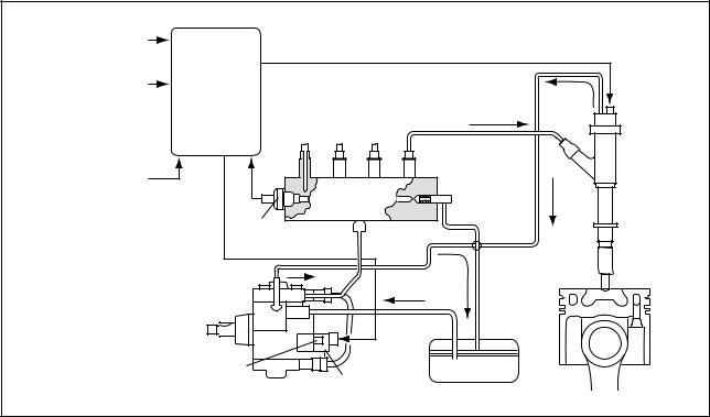
2-3. Comparison to The Conventional System |
||||
|
In-Line & VE Pumps |
Common Rail System |
|||
|
High-Pressure Pipe |
||||
|
Momentary High Pressure |
Supply |
Rail |
||
|
Timer |
Pump |
|||
|
Nozzle |
Normally High Pressure |
|||
|
Governor |
||||
|
System |
Delivery Valve |
|||
|
In-Line Pump |
||||
|
Feed |
SCV (Suction Control Valve) |
|||
|
Pump |
||||
|
Injector |
||||
|
Fuel Tank |
||||
|
VE Pump |
||||
|
Injection Quantity Control |
Pump (Governor) |
Engine ECU, Injector (TWV)*1 |
||
|
Injection Timing Control |
Pump (Governor) |
Engine ECU, Injector (TWV)*1 |
||
|
Rising Pressure |
Pump |
Engine ECU, Supply Pump |
||
|
Distributor |
Pump |
Engine ECU, Rail |
||
|
Injection Pressure Control |
Dependent upon speed and injection quantity |
Engine ECU, Supply Pump (SCV)*2 |
||
|
*1 TWV: Two Way Valve |
||||
|
*2 SCV: Suction Control Valve |
||||
|
Q000387E |
-3-
3. Outline of TOYOTA / HINO Small Truck Common Rail System
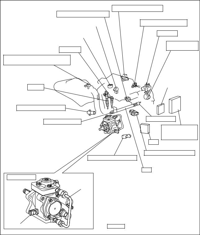
3-1. Main System Components
|
Accelerator Position Sensor |
|
|
Intake Air Temperature Sensor |
|
|
Variable Nozzle Type Turbo Opening Sensor |
Intake Air Pressure Sensor |
|
Variable Nozzle Type Turbo Motor |
EGR Valve |
|
Intake Restriction |
|
|
Glow Plug |
Step Motor |
|
Airflow Meter (With Integrated Ambient |
|
|
Air Temperature Sensor) |
|
|
Variable Nozzle |
|
|
Injector |
Controller |
|
Crankshaft Position Sensor |
|
|
Rail Pressure Sensor |
Pressure Limiter |
|
Engine ECU (With |
|
|
Built-In Atmospheric |
|
|
Pressure Sensor) |
|
|
EDU |
|
|
Coolant Temperature Sensor |
|
|
Cylinder Recognition Sensor |
|
|
Rail |
|
|
Supply Pump |
|
|
SCV |
|
|
Fuel Temperature Sensor |
Items are DENSO products |
|
Q000569E |
|
|
-4- |
3-2. Outline of Composition and Operation A. Composition
The common rail system consists primarily of a supply pump, rail, injectors, and engine ECU.
Fuel Temperature
Vehicle Speed 
Accelerator Opening 
Intake Air Pressure
Intake Air Temperature  Engine ECU
Coolant Temperature 
Crankshaft Position 
Cylinder Recognition Signal 
|
Intake Airflow Rate |
|||
|
Rail |
Pressure |
Injector |
|
|
Limiter |
|||
|
Rail |
|||
|
Pressure Sensor |
Fuel Temperature Sensor
|
Supply Pump |
SCV (Suction |
Fuel Tank |
|
|
Control Valve) |
|||
Q000144E
B. Operation
a.Supply Pump (HP3)
The supply pump draws fuel from the fuel tank, and pumps the high pressure fuel to the rail. The quantity of fuel discharged from the supply pump controls the pressure in the rail. The SCV (Suction Control Valve) in the supply pump effects this control in accordance with commands received from the engine ECU.
b.Rail
The rail is mounted between the supply pump and the injector, and stores the high-pressure fuel.
c.Injector (G2 Type)
This injector replaces the conventional injection nozzle, and achieves optimal injection by effecting control in accordance with signals from the engine ECU. Signals from the engine ECU determine the duration and timing in which current is applied the injector. This in turn, determines the quantity, rate and timing of the fuel that is injected from the injector. QR codes noting the characteristics of each vehicle are inscribed on the injector, and this data is sent to the ECU when the engine ECU or injectors are replaced. This enables software to be adjusted to the mechanical characteristics of each injector.
d.Engine ECU
The engine ECU calculates data received from the sensors to comprehensively control the injection quantity, timing and pressure.
-5-

3-3. Fuel System and Control System A. Fuel System
This system comprises the route through which diesel fuel flows from the fuel tank via the rail to the supply pump, and is injected through the injector, as well as the route through which the fuel returns to the tank via the overflow pipe.
B. Control System
In this system, the engine ECU controls the fuel injection system in accordance with signals received from various sensors. The components of this system can be broadly divided into the following three types: (a) sensors; (b) ECU; and (c) actuators.
a.Sensors
Detect the engine and driving conditions, and convert them into electrical signals.
b.Engine ECU
Performs calculations based on the electrical signals received from the sensors, and sends them to the actuators in order to achieve optimal conditions.
c.Actuators
Operate in accordance with electrical signals received from the ECU. Injection system control is undertaken by electronically controlling the actuators. The injection quantity and timing are determined by controlling the duration and timing in which current is applied to the TWV (Two-Way Valve) in the injector. Injection pressure is determined by controlling the SCV (Suction Control Valve) in the supply pump.
|
Sensor |
Actuator |
|||||||
|
Crankshaft Position Sensor NE |
Engine Speed |
|||||||
|
Injector |
||||||||
|
· Injection Quantity Control |
||||||||
|
Cylinder Recognition |
· Injection Timing Control |
|||||||
|
Cylinder Recognition Sensor G |
· Injection Pressure Control |
|||||||
|
Load |
Engine |
|||||||
|
Accelerator Position Sensor |
||||||||
|
ECU |
Supply Pump (SCV) |
|||||||
|
· Fuel Pressure Control |
||||||||
|
Rail Pressure Sensor |
||||||||
|
EGR, Air Intake Control |
||||||||
|
Relay, Light |
||||||||
|
Other Sensors and Switches |
||||||||
|
Q000390E |
||||||||
-6-
4. Description of Main Components
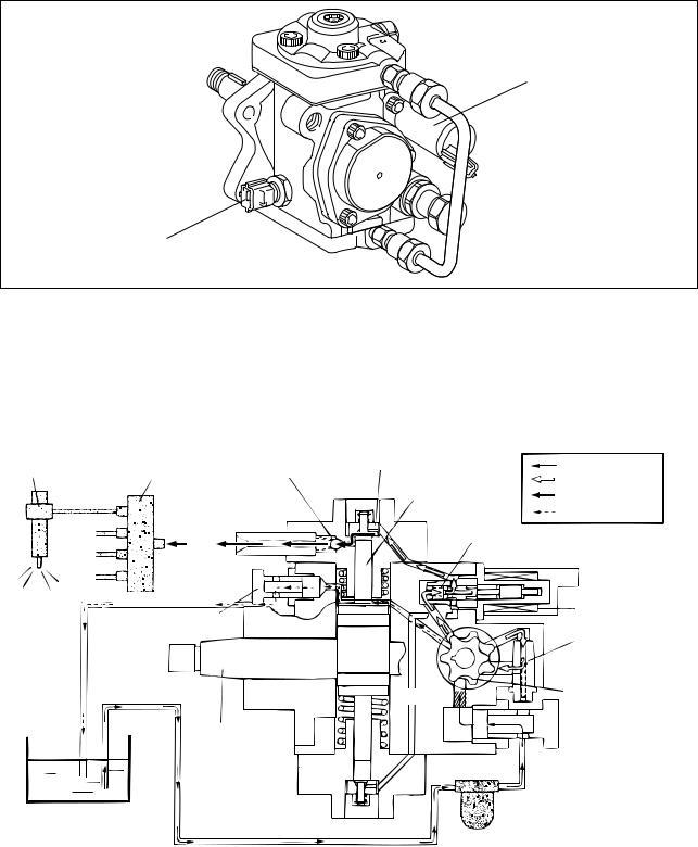
4-1. Supply Pump (HP3)
A.Outline
•The supply pump consists primarily of the pump body (camshaft (eccentric cam), ring cam, and plungers), SCV (Suction Control Valve), fuel temperature sensor, and feed pump.
SCV
Fuel Temperature Sensor
Q000570E
•The two plungers are positioned vertically on the outer ring cam for compactness.
•The engine drives the supply pump at a ratio of 1:1. The supply pump has a built-in feed pump (trochoid type), and draws the fuel from the fuel tank, sending it to the plunger chamber.
•The internal camshaft drives the two plungers, and they pressurize the fuel sent to the plunger chamber and send it to the rail. The quantity of fuel supplied to the rail is controlled by the SCV, using signals from the engine ECU. The SCV is a normally open type (the intake valve opens during de-energization).
|
Injector |
Rail |
Intake Valve |
Intake Pressure |
|||
|
Discharge Valve |
Feed Pressure |
|||||
|
Plunger |
High Pressure |
|||||
|
Return |
||||||
|
Return Spring |
||||||
|
Return |
||||||
|
Fuel Overflow |
SCV |
|||||
|
Regulating Valve |
||||||
|
Feed Pump |
||||||
|
Filter |
||||||
|
Camshaft |
Fuel Inlet |
|||||
|
Fuel Tank |
Intake Fuel Filter |
|||||
|
(With Priming Pump) |
||||||
|
Q000392E |
• The supply pump in the common rail system with DPNR has a fuel cut valve (FCV). The FCV is provided to enable manual shut-off if a fuel leak occurs in the fuel addition valve passage.
-7-
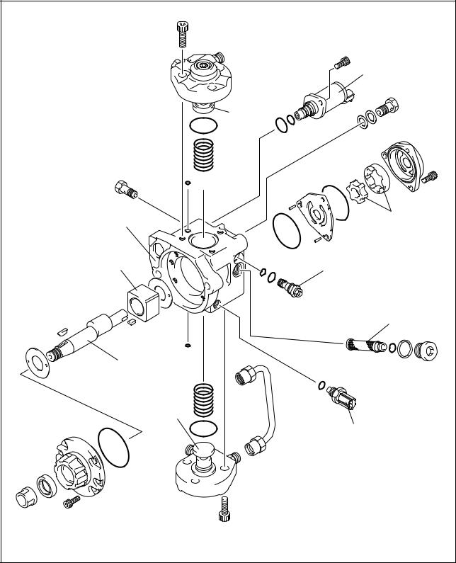
a.Supply Pump Exploded Diagram
|
SCV |
|
|
(Suction Control Valve) |
|
|
Plunger |
|
|
Pump Body |
Feed Pump |
|
Ring Cam |
Regulating Valve |
|
Filter |
|
|
Camshaft |
|
|
Plunger |
|
|
Fuel Temperature Sensor |
|
|
Q000393E |
|
|
-8- |

B. Supply Pump Internal Fuel Flow
Fuel drawn from the fuel tank passes through the route in the supply pump as illustrated, and is fed into the rail.
|
Supply Pump Interior |
|||||||||||||||||||||||
|
Regulating Valve |
|||||||||||||||||||||||
|
Feed Pump |
SCV (Suction Control Valve) |
Discharge Valve |
Rail |
||||||||||||||||||||
|
Overflow |
|||||||||||||||||||||||
|
Intake Valve |
Pumping Portion (Plunger) |
||||||||||||||||||||||
Fuel Tank
Q000394E
C.Construction of Supply Pump
•The eccentric cam is formed on the camshaft and is attached to the ring cam.
Ring Cam
Camshaft
Eccentric Cam
Q000395E
• As the camshaft rotates, the eccentric cam rotates eccentrically, and the ring cam moves up and down while rotating.
Eccentric Cam
Ring Cam
Camshaft
Q000396E
-9-
•The plunger and the suction valve are mounted on top of the ring cam. The feed pump is connected to the rear of the camshaft.
Plunger A
Ring Cam
Feed Pump
Plunger B
QD0728E
D. Supply Pump Operation
As shown in the illustration below, the rotation of the eccentric cam causes the ring cam to push Plunger A upwards. Due to the spring force, Plunger B is pulled in the opposite direction to Plunger A. As a result, Plunger B draws in fuel while Plunger A pumps it to the rail.
Suction Valve Delivery Valve
Plunger A
Eccentric Cam
Ring Cam
SCV
Plunger B
|
Plunger A: Finish Compression |
Plunger A: Begin IntakePlunger |
|
Plunger B: Finish Intake |
B: Begin Compression |
|
Plunger A: Begin Compression |
Plunger A: Finish Intake |
||||||||||||||||||||||||||
|
Plunger B: Begin Intake |
Plunger B: Finish Compression |
QD0707E
-10-
E. Description of Supply Pump Components
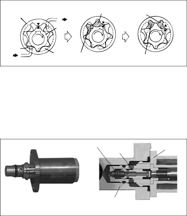
a.Feed Pump
The trochoid type feed pump integrated into the supply pump, draws fuel from the fuel tank and feeds it to the two plungers via the fuel filter and the SCV (Suction Control Valve). The feed pump is driven by the camshaft. With the rotation of the inner rotor, the feed pump draws fuel from its suction port and pumps it out through the discharge port. This is done in accordance with the space that increases and decreases with the movement of the outer and inner rotors.
Quantity Decrease
To Quantity Decrease (Fuel Discharge)
Pump Chamber
Outer Rotor
Inner Rotor
Intake Port
|
Discharge |
Quantity Increase |
Quantity Increase |
|
|
Port |
|||
|
From |
(Fuel Intake) |
||
|
Fuel Tank |
QD0708E |
||
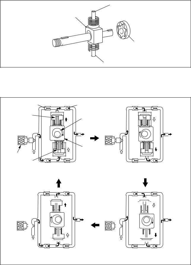
b.SCV (Suction Control Valve: Normally Open Type)
•A linear solenoid type valve has been adopted. The ECU controls the duty ratio (the duration in which current is applied to the SCV), in order to control the quantity of fuel that is supplied to the high-pressure plunger.
•The supply pump drive load decreases because intake fuel quantity is controlled to achieve the target rail pressure.
•When current flows to the SCV, the internal armature moves in accordance with the duty ratio. The fuel quantity is regulated by the cylinder, which moves in connection with the armature to block the fuel passage.
•With the SCV OFF, the return spring pushes the cylinder, completely opening the fuel passage and supplying fuel to the plungers. (Full quantity intake => full quantity discharge.)
•When the SCV is ON, the return spring contracts and closes the fuel passage.
•By turning the SCV ON/OFF, fuel is supplied in an amount corresponding to the drive duty ratio and then discharged by the plungers.
Return Spring
SCV
Cylinder
Pump Body
|
External View |
Cross-Section |
Q000050E
-11-
 Loading…

COMMON RAIL SYSTEM (CRS) SERVICE MANUAL: Operation
N04C-# Engine
Applicable Vehicle :Manufacturer Vehicle Name
TOYOTADYNACOASTER
HINO DUTRO
Issued : March 2007Revised : December 2009
00400058EB

© 2009 DENSO CORPORATIONAll rights reserved. This material may not be reproduced or copied, in whole or in part, without the written permission of DENSO Corporation.
Revision HistoryDate Revision Contents
2007.03 • Basic CRS content omitted, March, 2007 model CRS content added.Items added are as per the following:
APPLICABLE VEHICLES AND PRODUCT INFORMATIONMain components and SensorsEXHAUST GAS CONTROL SYSTEM (FEBRUARY 2007, JUNE 2009)“Engine ECU External Wiring Diagram” and “Connector Terminal Layout”ENGINE ECU DIAGNOSTIC TROUBLE CODES (DTC)
2009.12 • Basic CRS content omitted, June, 2009 model CRS content added.Items added are as per the following:
APPLICABLE VEHICLES AND PRODUCT INFORMATIONINJECTOR“Engine ECU External Wiring Diagram” and “Connector Terminal Layout”

Table of Contents
Operation Section
1. APPLICABLE VEHICLE AND PRODUCT INFORMATION1.1 Introduction . . . . . . . . . . . . . . . . . . . . . . . . . . . . . . . . . . . . . . . . . . . . . . . . . . . . . . . . . . . . . . . . . . . . . . . . . . . . 1-1
1.2 Applicable Vehicles . . . . . . . . . . . . . . . . . . . . . . . . . . . . . . . . . . . . . . . . . . . . . . . . . . . . . . . . . . . . . . . . . . . . . . 1-1
1.3 Applicable Product List . . . . . . . . . . . . . . . . . . . . . . . . . . . . . . . . . . . . . . . . . . . . . . . . . . . . . . . . . . . . . . . . . . . 1-2
2. SYSTEM OUTLINE2.1 Layout of Main Components . . . . . . . . . . . . . . . . . . . . . . . . . . . . . . . . . . . . . . . . . . . . . . . . . . . . . . . . . . . . . . . 1-5
3. SUPPLY PUMP3.1 Outline . . . . . . . . . . . . . . . . . . . . . . . . . . . . . . . . . . . . . . . . . . . . . . . . . . . . . . . . . . . . . . . . . . . . . . . . . . . . . . . . 1-6
3.2 Suction Control Valve (SCV) . . . . . . . . . . . . . . . . . . . . . . . . . . . . . . . . . . . . . . . . . . . . . . . . . . . . . . . . . . . . . . . 1-7
3.3 Fuel Temperature Sensor . . . . . . . . . . . . . . . . . . . . . . . . . . . . . . . . . . . . . . . . . . . . . . . . . . . . . . . . . . . . . . . . 1-10
4. RAIL4.1 Outline . . . . . . . . . . . . . . . . . . . . . . . . . . . . . . . . . . . . . . . . . . . . . . . . . . . . . . . . . . . . . . . . . . . . . . . . . . . . . . . 1-11
5. INJECTOR5.1 Outline . . . . . . . . . . . . . . . . . . . . . . . . . . . . . . . . . . . . . . . . . . . . . . . . . . . . . . . . . . . . . . . . . . . . . . . . . . . . . . . 1-12
6. CONTROL SYSTEM6.1 Control System Diagram . . . . . . . . . . . . . . . . . . . . . . . . . . . . . . . . . . . . . . . . . . . . . . . . . . . . . . . . . . . . . . . . . 1-15
6.2 Engine ECU. . . . . . . . . . . . . . . . . . . . . . . . . . . . . . . . . . . . . . . . . . . . . . . . . . . . . . . . . . . . . . . . . . . . . . . . . . . 1-16
6.3 Electronic Drive Unit (EDU) . . . . . . . . . . . . . . . . . . . . . . . . . . . . . . . . . . . . . . . . . . . . . . . . . . . . . . . . . . . . . . . 1-17
6.4 Sensors . . . . . . . . . . . . . . . . . . . . . . . . . . . . . . . . . . . . . . . . . . . . . . . . . . . . . . . . . . . . . . . . . . . . . . . . . . . . . . 1-18
7. EXHAUST GAS CONTROL SYSTEM (FEBRUARY 2007, AND JUNE 2009)7.1 Outline . . . . . . . . . . . . . . . . . . . . . . . . . . . . . . . . . . . . . . . . . . . . . . . . . . . . . . . . . . . . . . . . . . . . . . . . . . . . . . . 1-23
7.2 E-EGR System . . . . . . . . . . . . . . . . . . . . . . . . . . . . . . . . . . . . . . . . . . . . . . . . . . . . . . . . . . . . . . . . . . . . . . . . 1-23
7.3 DPF System . . . . . . . . . . . . . . . . . . . . . . . . . . . . . . . . . . . . . . . . . . . . . . . . . . . . . . . . . . . . . . . . . . . . . . . . . . 1-24
8. ENGINE ECU DIAGNOSTIC TROUBLE CODES (DTC)8.1 DTC Table . . . . . . . . . . . . . . . . . . . . . . . . . . . . . . . . . . . . . . . . . . . . . . . . . . . . . . . . . . . . . . . . . . . . . . . . . . . . 1-26
9. CONTROL SYSTEM COMPONENTS9.1 Engine ECU External Wiring Diagram. . . . . . . . . . . . . . . . . . . . . . . . . . . . . . . . . . . . . . . . . . . . . . . . . . . . . . . 1-33
9.2 Connector Terminal Layout . . . . . . . . . . . . . . . . . . . . . . . . . . . . . . . . . . . . . . . . . . . . . . . . . . . . . . . . . . . . . . . 1-57

Operation Section1–1
1. APPLICABLE VEHICLE AND PRODUCT INFORMATION
1.1 Introduction
This manual describes the Common Rail System (CRS) equipped with the NO4C-# engines used in the
HINO DUTRO, TOYOTA DYNA (both pickup trucks), as well as the TOYOTA COASTER (bus.)
For information on items common to all CRSs, refer to the previously published CRS general addition
manual (Doc ID: 00400076E). [Items common to all CRSs: CRS development process, system control,
construction and operation of main components (supply pump, rail, injectors.)]
1.2 Applicable Vehicles
November 2003
March 2007
June 2009
Vehicle Name Engine Model Remarks
DUTRO/DYNA N04C-TF
Vehicle Name Engine Model Destination Remarks
DUTRO/DYNA
N04C-TP
Europe
Vehicle power supply voltage: 24 V, EngineECU 12 V spec., with Diesel Particulate Filter(DPF), MT
N04C-TQ Vehicle power supply voltage: 24 V, MT withDPF
N04C-TR
GeneralVehicle power supply voltage: 24 V, EngineECU 12 V spec., MT
N04C-TS
N04C-TT
N04C-TU
Australia
Vehicle power supply voltage: 24 V, EngineECU 12 V spec., AT
N04C-TVVehicle power supply voltage: 24 V, EngineECU 12 V spec., MT
N04C-TW Europe, Hong KongVehicle power supply voltage: 24 V, EngineECU 12 V spec., with DPF, MT
COASTER
N04C-TQ Europe, Australia Vehicle power supply voltage: 24 V, with DPF,MT
N04C-TY China Vehicle power supply voltage: 24 V, MT
Vehicle Name Engine Model Remarks
DUTRO/DYNA/COASTER N04C-#

Operation Section1–2
1.3 Applicable Product List
November 2003
March 2007
Part Name DENSO Part Number Manufacturer Part Number Remarks
Supply Pump 294000-019# S2273-01264
Rail 095440-049# 22760-1170A
Injector 095000-532# 23910-1271A
Engine ECU 175800-658# 89660-37460
Electronic Drive Unit (EDU) 101310-539# 89870-37030
Accelerator Pedal Module 198800-315# 78100-37550
Crankshaft Position Sensor 029600-136# 89410-1630A
Camshaft Position Sensor 949979-131# 89410-1570A
Coolant Temperature Sensor 071560-011# 83420-1250A
Mass Air Flow (MAF) Meter 197400-200# 22204-21010
Intake Air Temperature Sensor 071500-249# 89441-4310A
Manifold Absolute Pressure(MAP) Sensor
079800-589# 89390-1080A
Exhaust Gas Recirculation(EGR) Valve
135000-705# 17350-1170A
Exhaust Gas TemperatureSensor
265600-060# (IN) 89441-37020 (IN)
265600-053# (OUT) 89441-37030 (OUT)
Part NameDENSO Part
Number
Manufacturer
Part NumberRemarks
Supply Pump 294000-059# 22100-E0060
294000-063# 22100-E0080 China Only
Rail 095440-098# 23810-E0010
Injector 095000-651# 23670-E0080
095000-652# 23670-E0090 General Only
095000-655# 23670-E0190 China Only

Operation Section1–3
EngineECU
DYNA/DUTRO
175800-799# 89661-37540 N04C-TQ, DPFVehicle power supplyvoltage: 24 V
175800-881# 89661-37590 N04C-TP, DPF
Vehicle power supply voltage: 24 V, Engine ECU 12 V specs.
175800-897# 89661-37600N04C-TW, DPF
175800-899# 89661-37610
175800-900# 89661-37620 N04C-TS
175800-902# 89661-37630 N04C-TT
175800-904# 89661-37640N04C-TV
175800-906# 89661-37650
175800-907# 89661-37550 N04C-TR
175800-909# 89661-37560 N04C-TS
175800-910# 89661-37570N04C-TU
175800-912# 89661-37580
EngineECU
COASTER 175800-863# 89661-36200N04C-TQ, DPF
Vehicle power supplyvoltage: 24 V175800-864# 89661-36210
175800-865# 89661-36180 N04C-TYVehicle power supplyvoltage: 12 V
175800-924# 89661-36220 N04C-TQ, DPFVehicle power supplyvoltage: 24 V
EDU 101310-539# 89870-37030 N04C-TQ
101310-571# 89870-37080
Accelerator PedalModule
198800-309# 78120-35460
198800-315# 78100-37750 N04C-TQ
EGR Valve 135000-721# 25620-E0010 Without N04C-TR, TS, TT
Camshaft PositionSensor
949979-131# 89410-1570A
Crankshaft PositionSensor
029600-136# 89410-1630A
MAF Meter 197400-200# 22204-21010
Exhaust GasTemperature Sensor
265600-053# 89425-37021 DPF, Upstream of Catalyst
265600-054# 89425-37031 DPF, Downstream of Catalyst
Differential PressureSensor
104990-102# 89480-37010DPF
Part NameDENSO Part
Number
Manufacturer
Part NumberRemarks

Operation Section1–4
June 2009
Part NameDENSO Part
Number
Manufacturer
Part NumberRemarks
Supply Pump 294000-059# 22100-E0060
Rail 095440-098# 23810-E0010
Injector095000-848# 23670-E0420 24 V use
095000-847# 23670-E0410 12V use
Engine ECU
275900-090# 89661-37540
175800-881# 89661-37590
175800-897# 89661-37600
175800-899# 89661-37610
175800-900# 89661-37620
175800-902# 89661-37630
EDU 101310-539# 89870-37030
Accelerator PedalModule
198800-309# 78120-35460 DUTRO right-hand driver vehicles
198800-326# 78100-37820 DUTRO left-hand driver vehicles
Accelerator PositionSensor
198300-815# 89281-26030 DYNA, COASTER
EGR Valve 135000-721# 25620-E0010
Camshaft PositionSensor
949979-131# 89410-1570A
Crankshaft PositionSensor
029600-136# 89410-1630A
Intake Air TemperatureSensor
072800-052# 89424-E0060
MAP Sensor 079800-740# 89420-37030
Differential PressureSensor
104990-102# 89480-37010

Operation Section1–5
2. SYSTEM OUTLINE
2.1 Layout of Main Components

Operation Section1–6
3. SUPPLY PUMP
3.1 Outline
The November 2003, and June 2009 model supply pumps are equipped with an SV1 type Suction Control
Valve (SCV). The March 2007 supply pump is equipped with an SV2 type SCV. Additionally, supply pumps
in the part number series 294000-059# are equipped with the SV1 type SCV as of June 2009. Supply pumps
in the part number series 294000-063# are equipped with the SV1 type SCV as of October 2007.
(1) November 2003 (294000-019#) , March 2007 (294000-063#*) and June 2009 (294000-059#)
* : Beginning from October 2007
(2) March 2007 (294000-059#, -063#)

Operation Section1–7
3.2 Suction Control Valve (SCV)
(1) November 2003 (294000-019#)
• The supply pumps in the part number series above are equipped with a conventional, normally open type SCV.
Operation Concept Diagram
Operation

Operation Section1–8
(2) March 2007 (294000-059#, -063#)
• The supply pumps in the part number series above are equipped with a compact, normally closed SCV.
Operation Concept Diagram
Operation

Operation Section1–9
(3) March 2007 (294000-063#*) and November 2009 (294000-059#)
• The supply pumps in the part number series above are equipped with a conventional, normally closed
type SCV
* : Beginning from October 2007
Operation Concept Diagram
Operation

Operation Section1–10
3.3 Fuel Temperature Sensor
A conventional sensor is used with the NO4C-# engine CRS. Sensor resistance values in relation to fuel
temperature are provided below.

Operation Section1–11
4. RAIL
4.1 Outline
Rails in the part number series 095440-049# have a flow damper to suppress fuel pulsations.
Since rails in the part number series 095440-098# have a built-in function to suppress fuel pulsations, there
is no flow damper.
(1) November 2003 (Rail: 095440-049#)
(2) March 2007, and June 2009 (Rail: 095440-098#)

Operation Section1–12
5. INJECTOR
5.1 Outline
The CRS detailed herein uses solenoid injectors with QR codes.
The injectors used in the June 2009 model CRS were designed to show improved responsiveness, as well
as to increase resistance against foreign material adherence to the nozzle.
(1) November 2003 (Injector: 095000-532#)

Operation Section1–13
(2) March 2007 (Injector: 095000-651#, -652#, -655#)

Operation Section1–14
(3) June 2009 (Injector: 095000-847#, -848#)

Operation Section1–15
6. CONTROL SYSTEM
6.1 Control System Diagram

Operation Section1–16
6.2 Engine ECU
General export vehicles for Europe, Oceania, and Asia use 12 V specification engine ECUs in relation to
the 24 V vehicle power supply (battery voltage). Accordingly, in the event that service such as repairs are
necessary, always verify the engine ECU specifications. To verify the specifications, look behind the
passenger seat back and check the engine ECU case, as well as whether or not there is a DC-DC converter.
< ATTENTION >When performing checks, do not apply vehicle power supply voltage to the engine ECU. If the
vehicle power supply voltage (24 V) is applied to a 12 V specification engine ECU, the ECU may be
damaged.
The figure below is an external view of the engine ECU. For the connector pin layout and external wiring
diagram: Refer to [Connector Terminal Layout] on P1-57.

Operation Section1–17
6.3 Electronic Drive Unit (EDU)
A conventional EDU is used with the NO4C-# engine CRS.
(1) Operation
• A high-voltage generating device converts the battery voltage into high voltage. The engine ECU sends signals to
terminals B through E of the EDU in accordance with the signals from each sensor. Upon receiving these signals, the
EDU outputs signals to the injectors from terminals K through N. At this time, terminal F outputs the IJf injection
verification signal to the ECU.
External Wiring Diagram

Operation Section1–18
6.4 Sensors
(1) Crankshaft position sensor and camshaft position sensor
• Conventional sensors are used as the crankshaft position sensor and camshaft position sensor. The crankshaft
position sensor is a Magnetic Pick Up (MPU) type sensor, while the camshaft position sensor is a Magnetic
Resistance Element (MRE) type.

Operation Section1–19
(2) Accelerator position sensor and accelerator pedal module
• A conventional hall element type sensor is used as the accelerator position sensor.
Accelerator Position Sensor: DYNA, COASTER

Operation Section1–20
Accelerator Pedal Module: DUTRO

Operation Section1–21
(3) Manifold Absolute Pressure (MAP) sensor
• The MAP sensor is used in the NO4C-TF engine. Sensor output voltage values in relation to absolute pressure are
provided below.
(4) Coolant temperature sensor
• The coolant temperature sensor is used in the NO4C-TF engine. Sensor resistance values in relation to coolant
temperature are provided below.

Operation Section1–22
(5) Mass Air Flow (MAF) meter
• A conventional sensor is used with the NO4C-# engine CRS.
Operation• When a heating element (heating coil) is placed in the air passage, the air absorbs heat and cools the heating
element. For this reason, the resistance value of the heating element decreases, and the current increases. As the
intake air volume increases, the cooling temperature of the heating element also increases. The hot-wire type airflow
meter utilizes the changes in the heating element.
One portion of the intake air passes by the heating element, and the temperature of the heating element resistor
changes in accordance with the intake air volume. The control circuit is used to ensure the temperature of the heating
element resistor is always constant. In other words, since the heating element becomes cooler as the airflow volume
increases, it is necessary to heat the element by increasing current flow through the resistor. This change in current
is converted into voltage by the control circuit IC.
However, even if the intake air volume is constant, the temperature of the heating element resistor changes according
to the intake air temperature. These changes result in errors when detecting the intake air volume. To correct these
errors, an additional intake air temperature compensator resistor (air thermometer) is used.

Operation Section1–23
7. EXHAUST GAS CONTROL SYSTEM (FEBRUARY 2007, AND JUNE 2009)
7.1 Outline
Both an Electric-Exhaust Gas Recirculation (E-EGR) and a Diesel Particulate Filter (DPF) system are used
to comply with Euro 4 emission regulations. The EGR valve, exhaust gas temperature sensor, and
differential pressure sensor are made by DENSO.
7.2 E-EGR System
The E-EGR system is an electronically controlled EGR system. The EGR system reduces NOx by lowering
the combustion temperature through re-circulating a portion of the exhaust gas to the intake manifold. Since
this system may also reduce engine output and decrease drivability, the EGR volume is controlled
electronically to an optimum level in accordance with driving conditions.
Both the electronically controlled EGR system and a high-capacity multipass system EGR cooler are used.
Engine performance has been increased through enabling high-volume exhaust gas recirculation.
A linear solenoid type valve is used as the actuator in the EGR valve. Simultaneous PM and NOx reduction
have been achieved by increasing EGR quantity adjustment precision.
An EGR valve lift sensor is also used. The EGR valve opening is fed back to the engine control computer
to enable optimal EGR control.
(1) Construction and operation
• To improve EGR exhaust gas purification performance, feedback control is performed using the EGR valve position.
Oxygen concentration in the intake air (which changes according to EGR) is controlled to a target value in accordance
with the engine state (engine speed, rising pressure, part temperatures, load and intake air volume.)
• To expand the EGR range, the lift sensor installed on the EGR valve performs feedback control of the
actual EGR quantity in relation to the pre-set target EGR quantity. Feedback control is based on the intake
restriction position and the variable nozzle turbo position.

Operation Section1–24
7.3 DPF System
A conventional DPF system is used with the NO4C-# engine CRS.

Operation Section1–25
(1) Exhaust gas temperature sensor
• A conventional sensor is used as the exhaust gas temperature sensor. Sensor resistance values in relation to exhaust
gas temperature are provided below.
(2) Differential pressure sensor
• A conventional sensor is used as the differential pressure sensor. Sensor output voltage values in relation to exhaust
gas differential pressure are provided below.

Operation Section1–26
8. ENGINE ECU DIAGNOSTIC TROUBLE CODES (DTC)
8.1 DTC Table
The following are Diagnostic Trouble Code (DTC) tables for November 2003, and March 2007 vehicles. The
«November 2003» DTC table is for conventional N04C-TF engines. The «March 2007» DTC table is for the
N04C-TP, Q, R, S, T, U, V, and W engines.
(1) November 2003
*1 : TCCS is the name designated by TOYOTA for DTCs resulting from the Malfunction Indicator Light(MIL). For details, refer to the CRS General Edition Manual (00400076E.)
*2 : The «A» in «A#» for TCCS represents a «10».
DTC Detection
Trip
Lamp
Output Detection Item
SAE TCCS*1 (CE)
P0030,P0031,P0130,P0131,P0132
21 1 A/F sensor (B1S1)
P0036,P0037,P0136,P0137,P0138
27 1 A/F sensor (B1S2)
P0087 49 1 Rail pressure abnormality (fixed output)
P0088 78 1 Suction Control Valve (SCV) abnormality (high-pressure in rail)
P0093 78 1 Fuel leak abnormality
P0095,P0097,P0098
23 1Intake air temperature sensor No. 2 (post-turbo intake airtemperature sensor)
P0100,P0102,P0103
31 1 Mass Air Flow (MAF) meter
P0105,P0107,P0108
35 1 Manifold Absolute Pressure (MAP) sensor
P0110,P0112,P0113
24 1 Intake air temperature sensor

Operation Section1–27
P0115,P0117,P0118
22 1 Coolant temperature sensor
P0120,P0122,P0123
41 1 Accelerator position sensor
P0168 39 1 Abnormally high fuel temperature
P0180,P0182,P0183
39 1 Fuel temperature sensor
P0190,P0192,P0193
49 1 Rail pressure sensor with back-up sensor
P0191 49 1 Rail pressure sensor with back-up sensor (out- of-range)
P0200 97 1 EDU abnormality (engine diagnostic)
P0234 34 1 VN turbo abnormality (closed-side abnormality)
P0263 78 1 Injector abnormality (FCCB abnormality) (No. 1 cylinder)
P0266 78 1 Injector abnormality (FCCB abnormality) (No. 2 cylinder)
P0269 78 1 Injector abnormality (FCCB abnormality) (No. 3 cylinder)
P0272 78 1 Injector abnormality (FCCB abnormality) (No. 4 cylinder)
P0299 34 1 VN turbo abnormality (open-side abnormality)
P033513 1
Crankshaft position sensor (open circuit/phase difference/powerflicker)
P0335 12 1 Crankshaft position sensor (open circuit)
P0339 13 1 Crankshaft position sensor (NE power flicker)
P0340 12 1 Crankshaft position sensor (open circuit/power flicker)
P0340 12 1 Camshaft position sensor (during start-up)
P0400 71 1 Exhaust Gas Recirculation (EGR) flow malfunction
P0400 71 1 EGR valve
P0405,P0406
96 1 EGR lift sensor
P0488 15 1 Intake restriction motor control system
P0500 42 1 Vehicle speed sensor (MT)
P0504 51 1 Stop light switch
P0607 89 1 CPU abnormality
P0627 78 1 Pump abnormality (open/short circuit)
P1133 00 1 Exterior accelerator position No. 1 sensor high
P1143 19 1 Throttle knob high
DTC Detection
Trip
Lamp
Output Detection Item
SAE TCCS*1 (CE)

Operation Section1–28
P1229 78 1 Pump valve abnormality
P1238 78 2 Injector injection abnormality
P1251 34 1 VN turbo (power flicker)
P1530 92 1 Emergency stop switch system
P1601 89 1 Multiple-point injector correction (EEPROM abnormality)
P1611 17 1 Internal IC abnormality
P1611 17 1 RUN pulse abnormality
P1674 36 1 Exhaust brake VSV system
P2120,P2122,P2123,P2125,P2127,P2128,P2138
19 1 Accelerator position sensor
P2121 19 1 Accelerator position sensor (out-of-range)
P2226,P2228,P2229
A5*2 1 Accelerator position sensor (open circuit)
DTC Detection
Trip
Lamp
Output Detection Item
SAE TCCS*1 (CE)

Operation Section1–29
(2) March 2007, and June 2009
*1 : TCCS is the name designated by TOYOTA for DTCs resulting from the Malfunction Indicator Light(MIL). For details, refer to the CRS General Edition Manual (00400076E.)
*2 : The «A» in «A#» for TCCS represents a «10».
DTC Detection
Trip
Lamp
Output Detection Item Remarks
SAE TCCS*1 (CE)
P0045 34 1 VN turbo (open)
P0087 49 1Rail pressure abnormality (fixed output)
P0088 78 1Suction Control Valve (SCV) abnormality (high-pressure in rail)
P0093 78 1 Fuel leak abnormality
P0095,P0097,P0098
23 1Intake air temperature sensor No. 2 (post-turbo intake air temperature sensor)
P0100,P0102,P0103
31 1 Mass Air Flow (MAF) meter
P0101 31 2 MAF meter (out-of-range)
P0105,P0107,P0108
35 1 MAP Sensor
P0106 35 2 MAP Sensor (out-of-range)175800-799#, -863#, 864# only
P0110,P0112,P0113
24 1 Intake air temperature sensor
P0115,P0117,P0118
22 1 Coolant temperature sensor
P0116 22 2Coolant temperature sensor (hightemperature out-of-range)
P0116 22 1Coolant temperature sensor (hightemperature stuck)
175800-865#, -899#, -900#, -902#, -904#, -906#, -907#, -909#, -910#, -912# only
P0120,P0122,P0123
41 1 Accelerator position sensor
P0168 39 1 Abnormally high fuel temperature
P0180,P0182,P0183
39 1 Fuel temperature sensor

Operation Section1–30
P0190,P0192,P0193
49 1Rail pressure sensor with back-up sensor
P0191 49 1Rail pressure sensor with back-up sensor (out- of-range)
175800-799#, -863#, 864# only
P0200 97 1EDU abnormality (engine diagnostic)
P0234 34 1VN turbo abnormality (closed-side abnormality)
P0263 78 1Injector abnormality (FCCBabnormality) (No. 1 cylinder)
P0266 78 1Injector abnormality (FCCBabnormality) (No. 2 cylinder)
P0269 78 1Injector abnormality (FCCBabnormality) (No. 3 cylinder)
P0272 78 1Injector abnormality (FCCBabnormality) (No. 4 cylinder)
P0299 34 1VN turbo abnormality (open-sideabnormality)
P0335 13 1Crankshaft position sensor (opencircuit/phase difference/powerflicker)
P0335 12 1Crankshaft position sensor (opencircuit)
P0339 13 1Crankshaft position sensor (NEpower flicker)
P0340 12 1Crankshaft position sensor (opencircuit/power flicker)
P0340 12 1Camshaft position sensor (duringstart-up)
P0400 71 2 EGR flow malfunction
P0400 71 1 EGR system malfunction
P0405,P0406
96 1 EGR lift sensor
P0405,P0406
96 1 EGR lift sensor
P0488 15 1Intake restriction motor controlsystem
P0500 42 2 Vehicle speed sensor (MT)
P0504 51 1 Stop light switch
DTC Detection
Trip
Lamp
Output Detection Item Remarks
SAE TCCS*1 (CE)

Operation Section1–31
P0544,P0545,P0546
A3*2 1Exhaust temperature sensorcircuit malfunction (in)
P0607 89 1 CPU abnormality
P0617 43 1 Starter abnormally high
P0627 78 1Fuel pump abnormality (Open/ short circuit)
P0630 89 1Vehicle Identification Number(VIN) not read
P0863 17 1 EFI ECT communication fault175800-865#, -899#, -900#, -902#, -904#, -906#, -907#, -909#, -910#, -912# only
P1133 00 1Exterior accelerator positionsensor high
P1143 19 1 Throttle knob high
P1229 78 1Fuel pump abnormality (open/short circuit)
P1238 78 2 Injector injection abnormality
P1251 34 1 VN turbo (power flicker)
P1425,P1427,P1428
A4*2 1Differential pressure sensor (opencircuit)
P1426 A4*2 1Differential pressure sensor(incorrect piping)
P1530 92 1 Emergency stop switch system
P1601 89 1Multiple-point injector correction(EEPROM abnormality)
P1611 17 1 Internal IC abnormality
P1611 17 1 RUN pulse abnormality
P1674 36 1 Exhaust brake VSV system
P2002 94 1 DPF system abnormality
P2031,P2032,P2033
A3*2 1 Exhaust temperature sensor (out)
P2120,P2122,P2123,P2125,P2127,P2128,P2138
19 1 Accelerator position sensor
DTC Detection
Trip
Lamp
Output Detection Item Remarks
SAE TCCS*1 (CE)

Operation Section1–32
P2121 19 1Accelerator position sensor (out-of-range)
P2226,P2228,P2229
A5*2 1Atmospheric pressure sensor(open circuit)
P2227 A5*2 2Atmospheric pressure sensor(out-of-range)
U0293 A2*2 1CAN communication (HV ECU:communication disruption) 175800-865#, -899#, -900#, —
902#, -904#, -906#, -907#, -909#, -910#, -912# onlyU1123 A2*2 1
VNT ECU CAN communication(reception abnormality)
DTC Detection
Trip
Lamp
Output Detection Item Remarks
SAE TCCS*1 (CE)

Operation Section1–33
9. CONTROL SYSTEM COMPONENTS
9.1 Engine ECU External Wiring Diagram
(1) November 2003
175800-658# (1)

Operation Section1–34
175800-658# (2)

Operation Section1–35
(2) March 2007
175800-799# (1)

Operation Section1–36
175800-799# (2)

Operation Section1–37
175800-863#, -864# (1)

Operation Section1–38
175800-863#, -864# (2)

Operation Section1–39
175800-865# (1)

Operation Section1–40
175800-865# (2)

Operation Section1–41
175800-899# (1)

Operation Section1–42
175800-899# (2)

Operation Section1–43
175800-900#, -902#, -907#, -909# (1)

Operation Section1–44
175800-900#, -902#, -907#, -909# (2)

Operation Section1–45
175800-904#, -910# (1)

Operation Section1–46
175800-904#, -910# (2)

Operation Section1–47
175800-906#, -912# (1)

Operation Section1–48
175800-906#, -912# (2)

Operation Section1–49
(3) June 2009
275900-087# (1)

Operation Section1–50
275900-087# (2)

Operation Section1–51
275900-089# (1)

Operation Section1–52
275900-089# (2)

Operation Section1–53
275900-090# (1)

Operation Section1–54
275900-090# (2)

Operation Section1–55
275900-136# (1)

Operation Section1–56
275900-136# (2)

Operation Section1–57
9.2 Connector Terminal Layout
(1) November 2003
175800-658#
(2) March 2007
175800-799#
175800-863#, -864#

Operation Section1–58
175800-865#
175800-899#
175800-900#, -902#, -907#, -909#
175800-904#, -910#

Operation Section1–59
175800-906#, -912#
(3) June 2009
275900-087#
275900-089#
275900-090#

Operation Section1–60
275900-136#

Service Department DENSO CORPORATION1-1, Showa-cho, Kariya-shi, Aichi-ken, 448-8661, Japan
Руководство ⇐ Dyna, ToyoAce. Двигатель
Модератор: jam
-
guo83
- Новичок
- Всего сообщений: 8
- Зарегистрирован: 29.07.2015
- Авто: Mazda Bongo, 2011, SKP2L, MKПП, 4 WD
- Откуда: Благовещенск
Руководство
А на бензиновый 1TR-FE случаем ни у кого не завалялась? Заранее спасибо
-

иванов иван02
- Полёт нормальный

- Всего сообщений: 1007
- Зарегистрирован: 03.11.2014
- Авто: Hyundai HD78, D4DD (CRDI), МКПП
- Откуда: РФ, Белгород

Руководство
Сообщение
иванов иван02 » 29 июл 2015, 20:11
guo83, насчёт двигателя 1TR-FE погуглил и обнаружил что они стоят на некоторых моделях Toyota Hilux например, поэтому смотрите в ссылках ниже.
Руководства по ремонту двигателей Toyota и сами посмотрите кому что надо здесь, только файлы долго грузятся с этого сайта.
-

myxomop.vl
- Зажигание
- Всего сообщений: 10
- Зарегистрирован: 08.07.2015
- Авто: Toyota Dyna 2002, 5L, 4wd
- Откуда: Владивостан, Приморье


Руководство
Сообщение
myxomop.vl » 03 авг 2015, 14:16
alik:Добрый день всем!!стал обладателем авто дюна 3L, есть ли у кого возможность скинуть рукаводство ([email protected]) за ранее благодарю!!!всем удачи!!!и зеленый цвет на дороге!!!
Отправлено спустя 2 минуты 5 секунд:
Добрый день всем!!стал обладателем авто дюна 3L, есть ли у кого возможность скинуть рукаводство ([email protected](ошибься с почтой маленькомаленько) за ранее благодарю!!!всем удачи!!!и зеленый цвет на дороге!!!
книга довольно объемная, лучше с торрента скачать сразу. Выше ссылку давали на nm-club, там можно скачать.
-
иванов иван02
- Полёт нормальный
- Всего сообщений: 1007
- Зарегистрирован: 03.11.2014
- Авто: Hyundai HD78, D4DD (CRDI), МКПП
- Откуда: РФ, Белгород
Руководство
Сообщение
иванов иван02 » 03 авг 2015, 15:25
myxomop.vl, зачем вводите людей в заблуждение ?
Откройте ссылку в моём предыдущем сообщении, пролистайте страницу и увидите прямую ссылку на мануал по двигателю 3L.

-
myxomop.vl
- Зажигание
- Всего сообщений: 10
- Зарегистрирован: 08.07.2015
- Авто: Toyota Dyna 2002, 5L, 4wd
- Откуда: Владивостан, Приморье
Руководство
Сообщение
myxomop.vl » 08 авг 2015, 12:14
иванов иван02:myxomop.vl, зачем вводите людей в заблуждение ?
Откройте ссылку в моём предыдущем сообщении, пролистайте страницу и увидите прямую ссылку на мануал по двигателю 3L.
Да и в мыслях не было людей путать) Я лишь предложил воспользоваться методом, которым и я сам воспользовался с вашей разумеется помощью ![]()
Тот манул что я скачал с торрента по весу 177м)
Newbie truck driver
-
иванов иван02
- Полёт нормальный
- Всего сообщений: 1007
- Зарегистрирован: 03.11.2014
- Авто: Hyundai HD78, D4DD (CRDI), МКПП
- Откуда: РФ, Белгород
Руководство
Сообщение
иванов иван02 » 09 авг 2015, 09:16
myxomop.vl, насколько я понимаю там мануал по нескольким двигателям а человек спрашивал за конкретную модель двигателя.
-
myxomop.vl
- Зажигание
- Всего сообщений: 10
- Зарегистрирован: 08.07.2015
- Авто: Toyota Dyna 2002, 5L, 4wd
- Откуда: Владивостан, Приморье
Руководство
Сообщение
myxomop.vl » 14 авг 2015, 15:40
иванов иван02:myxomop.vl, насколько я понимаю там мануал по нескольким двигателям а человек спрашивал за конкретную модель двигателя.
да, этого я не учел)
Newbie truck driver
-
Ceilor2002
- Новичок
- Всего сообщений: 1
- Зарегистрирован: 14.09.2015
- Авто: ToyoAce 2005г. isuzu elf 1992.,Land cruiser Prado
- Возраст: 36
Re: Руководство
Сообщение
Ceilor2002 » 14 сен 2015, 08:21
Люди!!! Поможите!!! =) нужен мануал на Тойоайс 2005 года с двигателем N04C поменял двигатель и автомат, а машинка, того, не едет….. выручайте , за ранее благодарен. вот почта; [email protected]
-
иванов иван02
- Полёт нормальный
- Всего сообщений: 1007
- Зарегистрирован: 03.11.2014
- Авто: Hyundai HD78, D4DD (CRDI), МКПП
- Откуда: РФ, Белгород
Re: Руководство
Сообщение
иванов иван02 » 17 сен 2015, 17:41
-
Awesome
- Новичок
- Всего сообщений: 3
- Зарегистрирован: 05.05.2017
- Авто: Hino Dutro
- Откуда: Владивостооок
Re: Руководство
Сообщение
Awesome » 05 май 2017, 01:39
Привет если кто живой тут еще. 2015 год последнее сообщение))
Купил гибридный hino dutro(N04C-TE, XKU304), мануал не могу найти нигде(проблема у меня с гибридной установкой). Если у кого есть — премного благодарен [email protected]
Спасибо!!!!!
-
friz1941
- Новичок
- Всего сообщений: 1
- Зарегистрирован: 31.03.2018
- Авто: Toyota toyoace 2005 n04ct 4wd
- Откуда: Красноярск
Re: Руководство
Сообщение
friz1941 » 31 мар 2018, 23:58
Здравствуйте уважаемые форумчане! Досталась мне по работе toyoace xzu 388,двс n04ct,рефка,4 wd.Может есть у кого букварь на нее по ремонту и эксплуатации?Скиньте пожалуйста,можно на адрес [email protected].Заранее благодарю откликнувшихся ![]()
-
Kayon
- Новичок
- Всего сообщений: 1
- Зарегистрирован: 16.05.2018
- Авто: Toyota Toyoace 2003 г. Двигатель 1RZ
- Откуда: Алтайский край
Re: Руководство
Сообщение
Kayon » 16 май 2018, 07:43
Уважаемые форумчане! Выручайте. Нужно руководство по ремонту Toyota Toyoace, с 1999 г. выпуска.
[email protected]
Заранее благодарен!
-
Станислав Че
- Новичок
- Всего сообщений: 1
- Зарегистрирован: 04.10.2018
- Авто: toyota dyna, 2003 г.в., ДВС- S05D, МКПП
- VIN: xzu411-0008540
- Откуда: иркутск
- Возраст: 34
Re: Руководство
Сообщение
Станислав Че » 04 окт 2018, 17:18
Всем привет! вот наконец-то приобрел себе Дюнку, перелазил весь интернет в поисках двух книг, купить без проблем, а файлы, сканы, увы, не нашел. Может у кого есть, поделитесь!
— Книга Hino двигатели J05c, S05c, S05c-b, S05c-ta, S05c-tb, S05d. Hino Dutro, Toyota Dyna, Toyoace. Диагностика. Руководство по ремонту и эксплуатации грузового автомобиля.
— КНИГА TOYOTA DYNA, TOYOACE, HINO DUTRO С 1999 ДИЗЕЛЬ. ПРОФЕССИОНАЛ. РУКОВОДСТВО ПО РЕМОНТУ И ЭКСПЛУАТАЦИИ ГРУЗОВОГО АВТОМОБИЛЯ
-

konstantin.mazyar
- Новичок
- Всего сообщений: 1
- Зарегистрирован: 21.11.2018
- Авто: Hino Dutro 1999
- Откуда: Красноярск
- Возраст: 39

Re: Руководство
Сообщение
konstantin.mazyar » 21 ноя 2018, 17:41
Доброго времени суток! Поделитесь пожалуйста руководством: Книга «Toyota Dyna и ToyoAce / Hino Dutro с 1999 г. Устройство, техническое обслуживание и ремонт.
[email protected]
Заранее благодарен! ![]()
-
Сергей Сава
- Новичок
- Всего сообщений: 2
- Зарегистрирован: 22.02.2019
- Авто: toyota toyo ace 1997 год, Шасси LY 211, МКПП
- Откуда: Благовещенск
Re: Руководство
Сообщение
Сергей Сава » 22 фев 2019, 12:21
Всем привет, я так понял что мануала на Toyo Ace 3L, LY211 ни у кого нет?!
Отправлено спустя 44 минуты 18 секунд:
вечер добрый, будьте так добры скиньте мануал на Toyo Ace двигатель 3L, LY211. доступ на ссылки, приведенные выше, закрыт, заранее спасибо- [email protected]
Отправлено спустя 36 минут 47 секунд:
ser-valua, Не могу найти на 3L, случайно нет? [email protected]
-
Сергей Сава
- Новичок
- Всего сообщений: 2
- Зарегистрирован: 22.02.2019
- Авто: toyota toyo ace 1997 год, Шасси LY 211, МКПП
- Откуда: Благовещенск
Re: Руководство
Сообщение
Сергей Сава » 23 фев 2019, 05:36
Нет, никто не делиться
Отправлено спустя 32 минуты 54 секунды:
TOYOTA TOYOACE G15 / DYNA 150 1995-2001 дизель Пособие по ремонту и эксплуатации. Есть такое????
-
IgorShakaleev
- Новичок
- Всего сообщений: 1
- Зарегистрирован: 13.01.2020
- Авто: Toyota dyna 2002г.в. S05c xzu307
- Откуда: Республика хакасия
Re: Руководство
Сообщение
IgorShakaleev » 13 янв 2020, 08:16
Доброго времени суток. Нужна схема электропроводки на toyota dyna 2002, s05c, xzu307. Пожалуйста кто может отправить пожалуйста на ящик. [email protected]
PS было бы здорово если бы и книжку скинули «КНИГА TOYOTA DYNA, TOYOACE, HINO DUTRO С 1999 ДИЗЕЛЬ. РУКОВОДСТВО ПО РЕМОНТУ И ЭКСПЛУАТАЦИИ ГРУЗОВОГО АВТОМОБИЛЯ.»
PS2 заранее большое спасибо!
-
Василий1988
- Новичок
- Всего сообщений: 1
- Зарегистрирован: 13.05.2020
- Авто: Toyota toyoace 2003, xzu307 , s05c, МКПП
- VIN: 0010905
- Откуда: Иркутск
Re: Руководство
Сообщение
Василий1988 » 13 май 2020, 06:08
Здравствуйте скиньте пожалуйста у кого есть:
— Hino Dutro, Toyota Dyna, Toyoace двигатели J05c, S05c, S05c-b, S05c-ta, S05c-tb, S05d.
-Hino Dutro, Toyota Dyna, Toyoace дизель с 1999г Руководство по ремонту и эксплуатации грузового автомобиля.
[email protected] Заранее огромное спасибо
-
pavel_sbr
- Новичок
- Всего сообщений: 1
- Зарегистрирован: 11.11.2021
- Авто: Hino Dutro
- Откуда: Красноярск
Re: Руководство
Сообщение
pavel_sbr » 11 ноя 2021, 06:59
Здравствуйте!
Купил недавно грузовик Hino Dutro 2003 года. Если еще данная тема актуальна и у кого-то имеется книга «Toyota Dyna и ToyoAce / Hino Dutro с 1999 г. Устройство, техническое обслуживание и ремонт«.
Поделитесь пожалуйста на почту: izk-mail @ yandex . ru (без пробелов), или в личные сообщения. Заранее благодарен ![]()
![]()
- Руководство — dutro.jpg (9.61 КБ) 2530 просмотров

-
- 15 Ответы
- 20209 Просмотры
-
Последнее сообщение sergey.markin
23 июн 2020, 01:17
-
- 5 Ответы
- 12907 Просмотры
-
Последнее сообщение Аваныч
29 июл 2017, 13:00
-
- 0 Ответы
- 5491 Просмотры
-
Последнее сообщение ctalin53
09 ноя 2011, 01:01
-
- 25 Ответы
- 29952 Просмотры
-
Последнее сообщение Форсунка
28 сен 2022, 11:24
-
- 0 Ответы
- 1313 Просмотры
-
Последнее сообщение МР3
15 апр 2012, 16:58
Дата публикации: 09.01.2023 22:57
Хиновод — это склад запчастей для ремонта Двигателя Хино (Hino) N04C. Мы подскажем какие запчасти понадобятся для замены. Замена прокладок, головки блока цилиндров. ДВС Хино (Hino) N04C. Установка головки блока. (Замена прокладки ГБЦ) Замена прокладок и установка ГБЦ Как заменить прокладку ГБЦ на двигателе Хино (Hino) N04C
Ремонт ГБЦ N04C — Установка Снятие и установка головки блока цилиндров (ГБЦ). Разборка и сборка головки. ремонт ГБЦ N04C. Как установить ГБЦ? Замена прокладки головки блока цилиндров как снять гбц и клапана Прокладки ГБЦ. Ремонт головки блока Хино (Hino) N04C.
Ремонт головки блока цилиндров Хино (Hino) N04C, ремонт двигателя, ремонт гбц, ремонт блока цилиндров, ремонт головок, ремонт клапанов, ремонт форсунок, ремонт впускного коллектора, ремонт выпускного коллектора.
Руководство по ремонту N04C. Руководство по ремонту, эксплуатации и техническому обслуживанию автомобилей Хино N04C. Инструкция по эксплуатации Содержание: Руководство на русском языке по эксплуатации, техническому обслуживанию и ремонту + каталог расходных запчастей автомобиля Хино 300 N04C
На нашем сайте вы можете купить запчасти двигателя на Хино (Hino) N04C. Мы предлагаем приобрести запчасти Хино от ведущих производителей Японии. Большой выбор запасных частей, низкие цены. Доставка запчастей в любой город России. Запчасти для двигателя, ходовой части и других узлов автомобиля. Для иномарок: оригинальные и качественные аналоги. Цены на сайте Хиновод