Содержание
- Двигатель Mercedes OM501LA
- Технические характеристики
- Модификации OM501LA
- Общий вид OM 501 LA
- Benz 501la Repair Manual
- Short Description
- Description
Двигатель Mercedes OM501LA
Двигатели OM501LA разрабатывались инженерами специально для установки на грузовики Actros («Актрос») – флагманскую модель грузового сектора компании Mercedes. Однако впоследствии этими моторами начали комплектовать и грузовики с меньшей грузоподъемностью.
 Двигатели OM 501 LA являются четырехтактными дизельными двигателями с непосредственным впрыском с водяным охлаждением. 6 цилиндров расположены V-образно под углом 90° и имеют отдельные ТНВД с коротким топливопроводом высокого давления к многоструйному распылителю, центрально расположенному по отношению к камере сгорания.
Технические характеристики
| Производство | Daimler Chrysler |
| Марка двигателя | OM 501 |
| Начало производства | 1996 |
| Тип | V-образный с наддувом турбокомпрессором, работающим от ОГ, и охлаждением наддувочного воздуха |
| Количество цилиндров | 6 |
| Ход поршня, мм | 150 |
| Диаметр цилиндра, мм | 130 |
| Объем двигателя, куб.см | 11946 |
| Мощность двигателя, л.с. | 313-428 |
| Крутящий момент, Нм/об.мин | 1850/1080 |
| Экологические нормы | Евро 3 |
| Вес двигателя, кг | 885 незаправленный, 935 заправленный |
| Расход топлива, л/100 км — при 60 км/час — при 80 км/час |
30.2 35.5 |
| Сколько масла в двигателе, л | 28-34 |
| Ресурс двигателя, тыс. км — по данным завода |
1 000 |
Модификации OM501LA
- OM 541.926 и OM 541.920 – мотор с мощностью 313 л.с., который предназначен для комплектации грузовиков относительно небольшой грузоподъемности и работающих на коротких и средних рейсах;
- OM 541.922 – двигатель с мощностью 354 л.с. для комплектации грузовиков, эксплуатируемых в самых различных условиях;
- OM 541.923 – двигатель мощностью 394 л.с. и самым низким потреблением топлива среди силовых агрегатов 501-й серии;
- OM 541.921 и OM 541.925 – двигатель с самым высоким значением мощности в 501-й серии в 428 л.с.
Двигатели имеют полноэлектронную систему регулирования, состоящую, наряду с двигателем и соответствующими датчиками, из блока управления системой регулирования двигателя (MR) и блока управления системой FR и/или других специфических для автомобиля блоков управления или гибких адаптирующих модулей (ADM).
Общий вид OM 501 LA

- Вентилятор;
- Насос охлаждающей жидкости;
- Напорный трубопровод наддувочного воздуха (с факельным устройством*) от охладителя наддувочного воздуха;
- Напорный трубопровод наддувочного воздуха к охладителю наддувочного воздуха;
- Маслоналивной патрубок;
- Турбокомпрессор, работающий от ОГ;
- Маслоотделитель трубопровода удаления воздуха из блок-картера;
- Выпускной трубопровод (с дроссельной заслонкой моторного тормоза);
- Масляный фильтр;
- Топливный фильтр;
- Стартер;
- Маслоизмерительный стержень.

- Масляный поддон;
- Блок управления системой регулирования двигателя (MR);
- Картер маховика;
- Выпускной коллектор;
- Топливный насос (с прифланцованным насосом гидроусилителя рулевого механизма);
- Воздушный компрессор;
- Резонатор (только в сочетании с воздушным компрессором);
- Кнопки ПУСКА-ОСТАНОВА;
- Генератор.

- Датчик уровня моторного масла;
- Позиционный датчик угла поворота коленчатого вала (на маховике);
- Датчик в. м. т. цилиндра 1 (на приводной шестерне распределительного вала);
- Датчик температуры топлива;
- Комбинированный датчик давления наддува/температуры наддувочного воздуха;
- Датчик температуры охлаждающей жидкости;
- Датчик давления моторного масла;
- Датчик температуры моторного масла.
Benz 501la Repair Manual
Short Description
Download Benz 501la Repair Manual.
Description
Powersystems • Industrial Engines Maintenance and Repair Series 457, 500 and 900 Advanced Training
Powersystems • Industrial Engines Maintenance and Repair Series 457, 500 d 900 Ad dT i i
This document is provided for training purposes only and is not subject to the normal updates.
Printed in Germany ã 2003 Copyright DaimlerChrysler AG Herausgeber: Global Training This documentation and all its constituent parts are subject to copyright. Any reproduction or reuse requires written permission from DaimlerChrysler AG in advance. This especially applies to any duplication, dissemination, editing, translation, and microfilming of this documentation, or storage and/or processing on electronic systems, databases and online services. 1511 1209 02
Note: The term «employee» always refers to both male and female staff.
Welcome . 1 Engine model series OM 457 LA. 2 Engine OM 457 LA . 4 Series 457Cylinder head. 11 Series 457Cylinder head — cross section (transverse and longitudinal) . 12 Series 457 LAPort assignments in the cylinder head gasket . 13 Series 457Cylinder head bolts — tightening instructions. 14 Series 457Setting valve play . 16 Series 457Removing/installing the nozzle holder combination. 19 Series 457Valve cover and valve cover gasket . 25 Series 457Oil pan . 26 Series 457Pump-line-nozzle injection system . 27 Series 457Removing/installing the MR/PLD unit pump. 28 Series 457Pistons . 35 Series 457Lubrication schematic diagram . 36 Series 457Oil spray nozzle. 38 Series 457Crankcase and cylinder liner . 39 Series 457Camshaft . 40 05/03
Powersystems • Industrial Engines Maintenance and Repair Series 457, 500 and 900 Advanced Training Content
Series 457Fuel system . 42 Series 457Fuel pump. 45 Series 457Fuel prefilter with heated water separator . 46 Series 457Planetary drive starter . 48 Series 457Fan drive and fan systems. 50 Series 457Air compressor . 52 Series 457Turbocharger BR S400 . 53 Series 457Engine oil and filter change . 54 Series 457Replacing the fuel filter . 56 Series 457Fuel filter with water separator — replacing the filter element. 58 Series 457Air cleaner, engine coolant service . 60 Series 500Engine models . 62 Series 500Technical features . 64 Series 500Cylinder head — port assignment . 70 Series 500Cylinder head. 71 Series 500Cylinder head mounting . 73 Series 500Cylinder head gasket. 74 Series 500EURO 2 and EURO 3 cylinder heads compared . 75 Series 500Valve assembly . 77 Series 500Pump-line-nozzle injection system (PLD) . 83 Series 500Removing/installing the MR/PLD unit pump. 91 Series 500EURO 2 and EURO 3 pistons . 101 05/03
Powersystems • Industrial Engines Maintenance and Repair Series 457, 500 and 900 Advanced Training Content
Series 500Connecting rod . 102 Series 500Crankcase. 103 Series 500Cylinder liners. 104 Series 500EURO 2 and EURO 3 cylinder liners compared . 107 Series 500Crankcase ventilation system . 108 Series 500Fuel system . 112 Series 500Oil cooler and oil filter housing – component locations. 124 Series 500Oil circuit . 128 Series 500Engine oil system. 129 Series 500Oil spray nozzle. 130 Series 500Water guide . 134 Series 500Thermostat location. 136 Series 500Supercharging system and charge air ducting . 137 Series 500Engine oil and filter change . 140 Series 500Cleaning the fuel prefilter / filter insert . 144 Series 500-Fuel prefilter with water separator — replacing the filter element . 146 Series 500Replacing the oil separator insert . 148 Series 500Replacing the fuel filter — air cleaner — coolant . 150 Engines OM 904 and 906 . 152 Engine series 900 . 153 Series 900Technical features . 156 Series 900Port assignments in the cylinder head gasket . 159 05/03
Powersystems • Industrial Engines Maintenance and Repair Series 457, 500 and 900 Advanced Training Content
Series 900Tightening instructions for cylinder head bolts . 160 Series 900Valve control. 162 Series 900Setting valve play . 164 Series 900Pump-line-nozzle injection system (PLD) . 167 Series 900Crankcase. 185 Series 900Ölspritzdüsen — Unterschiede . 188 Series 900Pistons and piston rings . 189 Series 900Connecting rod . 190 Series 900Pistons and connecting rod — modifications . 191 Series 900Engine oil circuit . 192 Series 900Removing/installing the oil pan . 196 Series 900Fuel system . 200 Series 900Supercharging system and charge air ducting . 212 Series 900Removing/installing the coolant thermostatic control . 216 Series 900Engine oil and filter change . 218 Series 900Cleaning the fuel prefilter — filter insert . 221 Series 900Fuel prefilter with water separator — replacing the filter element . 223 Series 900Replacing the fuel filter — air cleaner — coolant . 226
Powersystems • Industrial Engines Maintenance and Repair Series 457, 500 and 900 Advanced Training Content
Powersystems • Industrial Engines Maintenance and Repair Series 457, 500 and 900 Advanced Training Welcome
Series 500Engine models
The 500 engine model series is future-ready, and comes in V6 and V8 cylinder variants with 2 litre swept volume per cylinder.
Model series 500
The sales designation is formed in the same way as the 400 model series: 6-cylinder engine: OM 501 LA 8-cylinder engine: OM 502 LA At the same time, the OM 457 LA engine was developed with the same basic design as the Vengines. The Series 2000 V12 and V16 MTU engines are derived from the BR 500, and are intended for industrial applications.
OM 501 LA Turbocharger Charge air cooler 1=6-cylinder V-engine 2=8-cylinder V-engine Model series 500 Diesel engine
Powersystems • Industrial Engines Maintenance and Repair Series 457, 500 and 900 Advanced Training Series 500Engine models
The development of the 500 series encapsulates all the knowledge and experience gained from the 1 million V-engines manufactured since 1969, when production of the OM 403 V10 engine began.
Powersystems • Industrial Engines Maintenance and Repair Series 457, 500 and 900 Advanced Training Series 500Engine models
Series 500Technical features
Þ Outstanding power output and torque characteristics over the whole rpm range Þ Dynamic start-off characteristics and pulling power Þ Attractive power/weight ratio Þ Low fuel consumption Þ Enormous potential: the V6 engines meet the requirements of the highly popular 400 HP Class Þ High-pressure direct injection, pump-line-nozzle system with peak pressures up to 1,800 bar. Þ Electronic engine control (MR) with electronic system fixed to the engine, and extensive engine protection functions
Þ Viscous fan clutch, electromagnetic fan clutch and high-speed fan drive on the most powerful engines Þ Rated engine speed 1,800 rpm or 2000 rpm Þ Low maintenance requirement Þ Long maintenance intervals Þ Engine oil and fuel filter located at the front, for easy maintenance Þ Maintenance-free belt drive Þ Can run on FAME / RME (rape methyl ester) or biodiesel, and engine oil changes are halved Þ High reliability and long runtime Þ Low number of component variants, as many parts are the same on both 6 and 8 cylinder engines Þ Rear engine power take-off ex works
Þ Direct injection with centrally positioned 6-hole injection nozzle. Þ 4-valve technology Þ Useful engine brake rpm well over rated rpm, up to 2400 rpm Þ Meets the emission legislation of EURO 3 and EUROMOT/EPA Level 2 Þ Turbocharger with charge air cooling Þ V8 with 2 turbochargers
Powersystems • Industrial Engines Maintenance and Repair Series 457, 500 and 900 Advanced Training Series 500Technical features
Powersystems • Industrial Engines Maintenance and Repair Series 457, 500 and 900 Advanced Training Series 500Technical features
Overview of BR 500 engines with EURO 3 certification Engine model
No. of cylinders/ layout
[kW/HP (at rpm)] [Nm (at rpm)]
230/313 (1800) 1530 (1080)
260/354 (1800) 1730 (1080)
290/394 (1800) 1850 (1080)
300/408 (2000) 1900 (1080)
315/428 (1800) 2000 (1080)
320/435 (2000) 1900 (1080)
350/476 (2000) 2100 (1080)
350/476 (1800) 2300 (10809
370/503 (2000) 2300 (1080)
390/530 (1800) 2400 (1080)
420/571 (1800) 2700 (1080)
Powersystems • Industrial Engines Maintenance and Repair Series 457, 500 and 900 Advanced Training Series 500Technical features
Overview of BR 500 engines with EUROMOT/EPA Level 2 certification Engine model
No. of cylinders/ layout
[kW/HP (at rpm)] [Nm (at rpm)]
230/313 (1800) 1530 (1080)
260/354 (1800) 1730 (1080)
290/394 (1800) 1850 (1080)
315/428 (1800) 2000 (1080)
330/449 (1800) 2150 (1200)
350/476 (1800) 2300 (1200)
350/476 (2000) 2100 (1200)
380/517 (1800) 2400 (1200)
420/571 (1800) 2700 (1200)
448/609 (1800) 2700 (1200)
Powersystems • Industrial Engines Maintenance and Repair Series 457, 500 and 900 Advanced Training Series 500Technical features
Engine OM 501 LA in cross section
Powersystems • Industrial Engines Maintenance and Repair Series 457, 500 and 900 Advanced Training Series 500Technical features
Engine OM 502 LA in cross section
Powersystems • Industrial Engines Maintenance and Repair Series 457, 500 and 900 Advanced Training Series 500Technical features
Series 500Cylinder head — port assignment
Coolant Bolts Pressure oil Oil return Plunger, oil return
Powersystems • Industrial Engines Maintenance and Repair Series 457, 500 and 900 Advanced Training Series 500Cylinder head — port assignment
Series 500Cylinder head
The individual cylinder heads are made of high-quality molybdenum/cast iron alloy. Each has four stretchthread bolts (M18x2), with which it is bolted to the crankcase. The optimal position for the injection nozzle is the vertical position at the center of the combustion chamber. This ideal arrangement can only be achieved by using multi-valve technology. This consists in arranging the valves in pairs (2 intake, 2 exhaust) around the injection nozzle. A fifth valve is required for the constant throttle or the decompression valve/engine brake. In both cases, these are linked to the exhaust port through an exactly adjusted hole.
Powersystems • Industrial Engines Maintenance and Repair Series 457, 500 and 900 Advanced Training Series 500Cylinder head
The high-temperature, wear-resistant valve seat rings are inserted deep-frozen into the floor panel. The nozzle holder is inserted in a protective sleeve, which is washed around by coolant and thus individually cooled. The nozzle protective sleeve is sealed by an O-ring against coolant escape, and by the thread and face against gas escape.
Powersystems • Industrial Engines Maintenance and Repair Series 457, 500 and 900 Advanced Training Series 500Cylinder head
Series 500Cylinder head mounting
The cylinder head is tightened in 6 stages. The cylinder head bolts do not require retightening. Step 1
Powersystems • Industrial Engines Maintenance and Repair Series 457, 500 and 900 Advanced Training Series 500Cylinder head mounting
Series 500Cylinder head gasket
Each cylinder head has a stainless steel insert gasket with scorched elastomer binding, which does not require retightening.
Powersystems • Industrial Engines Maintenance and Repair Series 457, 500 and 900 Advanced Training Series 500Cylinder head gasket
Series 500EURO 2 and EURO 3 cylinder heads compared
Cylinder head old version, as of 04/99
In the previous Euro 2 version, the cover surfaces were milled. Since 2000, as part of the «Euro 3» package of measures, the cylinder head surfaces are turned, to a specific surface quality. Since 06/2000, this also applies to all Euro 2 V8 and 315 kW V6 engines, and from January 2001 to all other V6 engines.
Cylinder head, Euro 3 version
The new cylinder heads should be ground to a minimum height of 113.5 mm, by face grinding only. The surface quality (peak-to-valley height and corrugation depth) is to be observed in all cases.
Powersystems • Industrial Engines Maintenance and Repair Series 457, 500 and 900 Advanced Training Series 500EURO 2 and EURO 3 cylinder heads compared
Powersystems • Industrial Engines Maintenance and Repair Series 457, 500 and 900 Advanced Training Series 500EURO 2 and EURO 3 cylinder heads compared
Series 500Valve assembly
Gas exchange is improved by 4-valve technology, thus contributing considerably to lower fuel consumption with lower emissions. The intake and exhaust valves are controlled by means of roller tappets, push rods and intake and exhaust rocker arms which are set in a groove in the crankcase with a sliding block, and which operate the intake/exhaust valve pairs through a valve bridge. The rocker arm spindle complete with preassembled rocker arms and rocker arm bearing bracket is bolted to the cylinder head. To keep wear in the whole valve assembly to a minimum throughout its lifetime, the contact surfaces of the valve, valve bridge, the rocker arm thumb, the upset ball socket of the push rod, and the ball head of the adjusting screw, are induction hardened. This is to allow them to support the actuation forces of the high-temperature valve springs, and the effects of inertial forces and cylinder pressures.
Powersystems • Industrial Engines Maintenance and Repair Series 457, 500 and 900 Advanced Training Series 500Valve assembly
Camshaft The camshaft is made of high-strength material, with induction-hardened running surfaces, and has 4 bearings in the OM 501 LA, 5 bearings in the OM 502 LA. Between the bearings are 4 valve timing cams and 2 injection cams for each opposing cylinder pair. The slide ways of the timing cams for the valve and injection roller tappets are supplied with lube oil through additional oil holes in the piston jet pipe.
Powersystems • Industrial Engines Maintenance and Repair Series 457, 500 and 900 Advanced Training Series 500Valve assembly
Adjusting the valve play The valve play checking and setting procedure is the same as for the BR 400, and there are two methods. Method 1 Set the intake and exhaust valves for each cylinder, according to the injection sequence. The cylinder to be set must be at ignition TDC, the parallel cylinder at valve overlap TDC. With this method, the crankshaft must be turned six times in the 6-cylinder engine, and eight times in the 8-cylinder engine. Method 2 Set the intake and exhaust valves in two crankshaft positions. Adjust when cylinder 1 is at ignition TDC. Adjust when cylinder 1 is at overlap TDC. N05.30-0302-01 P
The valve play test tolerance applies only for checking valve play. If valve play is outside the tolerance range, the specified value must be set.
Powersystems • Industrial Engines Maintenance and Repair Series 457, 500 and 900 Advanced Training Series 500Valve assembly
General notes on valve adjustment Method 1 Set the intake and exhaust valves for each cylinder, according to the injection sequence. The cylinder to be set must be at ignition TDC, and the parallel cylinder at valve overlap TDC.
Exhaust valve Intake valve Flywheel side N01.00-0200-01
Powersystems • Industrial Engines Maintenance and Repair Series 457, 500 and 900 Advanced Training Series 500Valve assembly
General notes on valve adjustment Method 2 Set the intake and exhaust valves at two crankshaft positions, as shown in the table.
Exhaust valve Intake valve Flywheel side
First set cylinder 5 at valve overlap TDC (cylinder 1 at ignition TDC), then cylinder 1 at valve overlap TDC (cylinder 5 at ignition TDC).
First set cylinder 6 at valve overlap TDC (cylinder 1 at ignition TDC), then cylinder 1 at valve overlap TDC (cylinder 6 at ignition TDC).
Cylinder/injection sequence 1
Cylinder 5 valve overlap
Cylinder 1 valve overlap
Cylinder 6 valve overlap
Cylinder 1 valve overlap
Powersystems • Industrial Engines Maintenance and Repair Series 457, 500 and 900 Advanced Training Series 500Valve assembly
Powersystems • Industrial Engines Maintenance and Repair Series 457, 500 and 900 Advanced Training Series 500Valve assembly
Series 500Pump-line-nozzle injection system (PLD)
Engines of the OM 500 model series use the direct fuel injection process. The injection process is performed by the newly developed pump-line-nozzle (PLD) system, controlled by an electronic engine management system that has also been newly developed. In the PLD system, fuel is delivered to the injection nozzle by individual unit pumps over short, rigid high-pressure injection lines, and through the pressure pipe connection screwed into the cylinder head. The connection to the nozzle and nozzle holder is located centrally at the cylinder, and is integrated with, and removable from, the cylinder head. A unit pump fitted for each cylinder is located directly on the crankcase.
Powersystems • Industrial Engines Maintenance and Repair Series 457, 500 and 900 Advanced Training Series 500Pump-line-nozzle injection system (PLD)
The electronic engine management system controls the injection timing point and quantity injected individually per cylinder, by means of solenoid valves. Separation of the high pressure pump and injection nozzle made it necessary to develop a high pressure injection line of special tube material with a surface hardened by internal high pressure forming, able to support continuous injection pressures over 2000 bar. With high pressure injection (peak pressures up to 1800 bar) together with the central, vertically positioned nozzle with 8 or 6 injection orifices and flat combustion chamber cavity in the piston, outstanding particulate values are achieved.
Advantages over the Pump-Nozzle system ¦ No overhead camshaft — therefore lower space requirement and reduced engine height — lower noise emission ¦ On the V-engine, only one camshaft needed, which controls both cylinder banks. — Weight saving ¦ Locating the camshaft in the center of the crankcase means there is optimal power absorption. With an overhead camshaft, measures would be necessary for strengthening the cylinder head. ¦ Easy to repair — Individual cylinder heads, which are all identical — Compact unit pumps, which are simple to replace — Inexpensive replacement due to separate pump and nozzle
Powersystems • Industrial Engines Maintenance and Repair Series 457, 500 and 900 Advanced Training Series 500Pump-line-nozzle injection system (PLD)
Pressure pipe connection and nozzle holder location
Connection to the nozzle holder and injection nozzle (positioned vertically at the center of the cylinder), is through a fixed, preassembled pressure pipe connection with integral pin-type filter. The nozzle holder with 8 or 6-hole injection nozzle is held in a protective sleeve by means of a clamping claw supported on the nozzle holder and constant throttle cap, and attached with a central screw. The seal at the nozzle protective sleeve consists of a copper spacer or sealing sleeve. For nozzle holder positioning, the clamping claw grips a locating pin fixed into the nozzle holder cap. The pressure pipe connection is attached with a press-in ball fastening. 1 3 4 5.1
Injection line, 30 [Nm] Pressure screw, 40 [Nm] O-ring Pressure pipe connection with anti-twist lock (press-in ball fastening) 5.2 Pressure pipe connection without anti-twist lock 6 Nozzle holder combination 7 O-ring 8 Screw, 50 Nm, £ 91 mm 9 Retaining clip 10 Sealing ring 11
Constant throttle cap
Powersystems • Industrial Engines Maintenance and Repair Series 457, 500 and 900 Advanced Training Series 500Pump-line-nozzle injection system (PLD)
Removing/installing the nozzle holder combination 1 2 3 4 5.1 5.2 6 7 8 9 10 11 12 13 L
Injection line, 30 Nm Leak fuel line, 15 Nm Pressure screw, 40 Nm O-ring Pressure pipe connection with anti-twist lock (press-in ball) Pressure pipe connection without antitwist lock Nozzle holder combination O-ring Screw, 50 Nm Retaining clip Sealing ring or sealing sleeve Constant throttle cap Adapter 904 589 00 63 00 Extractor 355 589 01 63 00 Shank length of screw (8), £ 91 mm
Powersystems • Industrial Engines Maintenance and Repair Series 457, 500 and 900 Advanced Training Series 500Pump-line-nozzle injection system (PLD)
Risk of explosion due to gas ignition, risk of poisoning by inhaling or Fire, sparks, naked flames, smoking are forbidden. Only store fuel in absorbing fuel, or risk of injury to skin and eyes through contact with fuel. suitable and appropriately marked containers. Wear protective clothing if handling fuel. Remove the cylinder head cover
Remove leak fuel line (2) from cylinder head
Remove injection line (1)
Unscrew pressure screw (3) and remove pressure pipe connection (5).
Remove retaining clip (9)
Fit the adapter (12) and extractor (13) to the inside thread (M  of nozzle Adapter: 904 589 00 63 00 holder combination (6) Extractor: 355 589 01 63 00 Take out the nozzle holder combination (6) The nozzle holder combination should not be disassembled. If worn or faulty, the nozzle holder combination must be replaced. Remove the adapter (12) and extractor (13) from nozzle holder combination (6) Take out the sealing ring (10)
Measure the shank length of screw (8).
i If the maximum shank length is exceeded, replace the screw. MB Standard 10105 screws are generally to be replaced by screws with an MB Part No. on the screw head.
Insert a new O-ring (7) at nozzle holder combination (6)
Place the new O-ring (10.1) at nozzle holder combination (6)
i Grease the O-ring. i Up to engine End Number 197928 Note the installation location and thickness of the sealing ring: the smaller ring surface should point towards the nozzle holder combination. Grease the sealing ring.
Powersystems • Industrial Engines Maintenance and Repair Series 457, 500 and 900 Advanced Training Series 500Pump-line-nozzle injection system (PLD)
Press new sealing sleeve (10.2) onto nozzle holder combination (6)
i From engine End Number 197928 Before pressing on the new sealing sleeve, the contact surface of the sealing sleeve should be cleaned to remove combustion residues (using a wire brush or ultrasonic equipment, for example). #Clean the nozzle holder combination. i Grease the sealing sleeve. l
Install nozzle holder combination (6)
iNote installation location of nozzle holder combination at the pressure pipe connection hole. Twist the nozzle holder combination with retaining clip (9) into the cylinder head until the retaining clip (9.1 or 9.2) clips onto the locating pin on the cap of constant throttle (11).
Mount the retaining clip (9.1 or 9.2), 50 Nm
Place the new O-ring (4) at pressure pipe connection (5).
Fit the pressure pipe connection (5.1 or 5.2) and tighten pressure screw (3),40 Nm
i Grease the O-ring. i Pressure pipe connections with anti-twist lock (5.1, press-in ball) should not be fitted to cylinder heads without a groove (arrowed). The ball (arrowed) must be inserted in the groove (arrowed). Damaged pressure pipe connections with an anti-twist lock can be replaced by the modified pressure pipe connection without anti-twist lock (5.2). i Moisten the pressure pipe connection around the taper seal with engine oil. n
Install the injection line (1)
Fit the leak fuel line (2), 15 Nm
Fit the cylinder head cover
Powersystems • Industrial Engines Maintenance and Repair Series 457, 500 and 900 Advanced Training Series 500Pump-line-nozzle injection system (PLD)
Powersystems • Industrial Engines Maintenance and Repair Series 457, 500 and 900 Advanced Training Series 500Pump-line-nozzle injection system (PLD)
Extracting tool 906 589 02 63 00 is now usually supplied together with the extension. From April 2003, for new orders under the existing number, special tool 906 589 00 63 00 is supplied with modification to Part 1. To extend existing tools, the modified Part 1 can also be ordered separately under number 906 589 00 63 01.
Powersystems • Industrial Engines Maintenance and Repair Series 457, 500 and 900 Advanced Training Series 500Pump-line-nozzle injection system (PLD)
Extracting tool extension
Series 500Removing/installing the MR/PLD unit pump
MR/PLD unit pump O-ring (black)
O-ring (brown) Protective sleeve 541 589 01 14 00
Splined bolt, 65 Nm Cable duct with engine wiring harness
Powersystems • Industrial Engines Maintenance and Repair Series 457, 500 and 900 Advanced Training Series 500Removing/installing the MR/PLD unit pump
Extractor 355 589 01 63 00 Injection line, M16x1.5, 50Nm
Risk of explosion due to gas ignition, risk of poisoning by inhaling or Fire, sparks, naked flames, smoking are forbidden. Only store fuel in absorbing fuel, or risk of injury to skin and eyes through contact with fuel. suitable and appropriately marked containers. Wear protective clothing if handling fuel.
Remove the charge air pipe
Remove injection line (8)
Stop up the orifices in the nozzle holder combination and MR/PLD unit pump (1).
Clean the crankcase around the MR/PLD unit pumps (1).
Cover the intake orifices in the cylinder heads.
Remove engine wiring harness (6) at all MR/PLD unit pumps (1) on left or To do this, loosen the screws on the solenoid valve and detach both clip right. fasteners.
Identify the MR/PLD unit pump (1) for the cylinder concerned
Only if removing more than one or all MR/PLD unit pumps
Loosen the splined bolts (5)
For reasons of safety, the splined bolts should be unscrewed by only about 4 to 5 mm; the MR/PLD unit pump is under spring load. Installation: Press the MR/PLD unit pump into the crankcase with the splined bolts, tightening slowly and alternating between bolts. Tighten the splined bolts to 65 Nm
Fit the extractor (7) to MR/PLD unit pump (1)
Extractor: 355 589 01 63 00
Powersystems • Industrial Engines Maintenance and Repair Series 457, 500 and 900 Advanced Training Series 500Removing/installing the MR/PLD unit pump
Pull out the MR/PLD unit pump (1) with the extractor (355 589 01 63 00) Remove the fuel lines or fuel overflow valve on the crankcase if necessary. up to the bolt heads Banjo bolt of fuel line to port in crankcase, 50Nm. Banjo bolt of fuel line to fuel overflow valve, 50 Nm. If stuck, the MR/PLD unit pump should not be pressed out at the solenoid valve and housing flange. Carefully press out the MR/PLD unit pump at the cutout (arrowed) in the unit pump housing. Installation: Lightly oil the unit pump body, O-ring surfaces (2, 3), and hole in the crankcase with engine oil. Do not tilt the MR/PLD unit pump when inserting in the crankcase. Carefully press in the MR/PLD unit pump by hand, to a depth of about 4 mm. If the unit pump cam on the camshaft is at the top, turn the engine by a half-revolution (in direction of rotation).
Unscrew the splined bolts (5) and pull out the MR/PLD unit pump (1)
Installation: Carefully remove dirt and paint residues from the sealing surface (arrowed) of the MR/PLD unit pump and crankcase.
Check the MR/PLD unit pump
Check the roller on roller tappet; if there is only slight scoring or scratching, the MR/PLD unit pump can be used again. If there is deep scoring, scratching, or sanding spots: Install a new MR/PLD unit pump
Remove O-rings (2, 3) from the MR/PLD unit pump (1)
Installation: Clean the radial groove in the unit pump body. Push protective sleeve (541 589 01 14 00) over the unit pump body, coat the new O-rings with engine oil; slip the black O-ring, (2) over the protective sleeve into the top groove, then the brown O-ring (3) into the lower groove. Avoid twisting the O-rings when fitting into the grooves.
Install in the reverse order
Powersystems • Industrial Engines Maintenance and Repair Series 457, 500 and 900 Advanced Training Series 500Removing/installing the MR/PLD unit pump
Unit pump classification The BR 457, 500 and 900 unit pumps are classified at manufacture.
When each pump is installed in the engine on the assembly line at Mannheim, its classification is registered and stored in the MR electronic system. To ensure smooth engine running, the classification values are taken into account when distributing the fuel quantity (injection timing). To ensure that smooth engine running continues after unit pumps are replaced or modified for diagnostic purposes, the unit pump classification must be assigned to the cylinder. An input error may lead to rough engine running and overloading of individual cylinders. Then reset the individual cylinder torque control to «0».
Replace unit pump Cylinder
Note: The user must read off the unit pump number on the unit pump, and enter it for the corresponding cylinder. Only enter the unit pump number for pumps being replaced. To confirm, press F3.
Powersystems • Industrial Engines Maintenance and Repair Series 457, 500 and 900 Advanced Training Series 500Removing/installing the MR/PLD unit pump
The classification is coded as a 14-digit number (C) on the unit pump model plate. The code is entered through the «Replace Unit Pump» menu in DAS. A= B= C= D= E, G, H = F=
MB number Certification number Unit pump number (classification) Bar code Manufacturer information Manufacturer bar code
Powersystems • Industrial Engines Maintenance and Repair Series 457, 500 and 900 Advanced Training Series 500Removing/installing the MR/PLD unit pump
355 589 01 63 00
Powersystems • Industrial Engines Maintenance and Repair Series 457, 500 and 900 Advanced Training Series 500Removing/installing the MR/PLD unit pump
541 589 01 14 00
Sealing the intermediate plate of the unit pump
Powersystems • Industrial Engines Maintenance and Repair Series 457, 500 and 900 Advanced Training Series 500Removing/installing the MR/PLD unit pump
lScrewdriver bit lSleeve
To remove Utmost cleanliness should be ensured whenever working on the unit pumps. Remove the MR/PLD unit pump Remove O-rings (8,9,) from the unit pump (1)
Push the sleeve (11) onto unit pump (1)
Clean the upper part of the MR/PLD unit pump.
p First clean the bottom part of the pump body (1). p So that dirt will not get into the orifices. l p Carefully remove paint residues on the sealing surfaces of the MR/PLD unit pump. i The high pressure orifice must be closed off. No dirt or cleaning agent should be allowed to penetrate into the pump body (1).
Identify the intermediate plate (3) (arrow A) for the pump body (1) and place the MR/PLD unit pump at the stop plate.
p Use a scriber or touch-up pencil, never a stamping tool.
Loosen the screws (6), and remove solenoid (4) together with intermediate plate (3) and model plate.
i First remove paint residues from the screw heads with a scriber (arrow B).
Remove intermediate plate (3) and model plate (5) from solenoid (4).
Take out sealing rings (2) and clean intermediate plate (3)
Identify the crosspiece (1.2) and anchor plate (1.1) for pump body (1) (arrow C).
Apply cleaning spray to the sealing surfaces of pump body (1), crosspiece (1.2) and anchor plate (1.1).
Powersystems • Industrial Engines Maintenance and Repair Series 457, 500 and 900 Advanced Training Series 500Removing/installing the MR/PLD unit pump
l i Clean the sealing surface of the solenoid. p Do not damage the sealing surfaces. p Use a touch-up pencil, never a scriber or stamping tool. The crosspiece should not be moved or turned. p Clean the parts carefully. i Do not remove paint residues from the pump body (1), these will be needed for locating the intermediate plate (3).
Take off stop plate (7)
Clean the model plate (5)
To install Place new stop plate (7) under the pump body (1).
Insert new seals (2) in the intermediate plate (3).
Place intermediate plate (3) on pump body (1).
p Remove paint residues around the contact surface of the screw heads. Do not remove the protective foil on the model plate.
i Protect the seals with grease p Pay attention to the identification marks on the crosspiece (1.2) and anchor plate (1.1) for pump body (1). The cutouts (arrows D) at the opening in the intermediate plate must point towards the crosspiece (1,2). i The paint residues are used to locate intermediate plate (3) on pump body (1).
Insert the solenoid (4) on intermediate plate (3).
Assemble the model plate (5), solenoid(4), intermediate plate (3), pump body (1) and stop plate (7) and fasten with new screws (6).
ni Tighten the screws crosswise. l904 589 02 10 00
Take off sleeve (11)
Install MR/PLD unit pumps
Powersystems • Industrial Engines Maintenance and Repair Series 457, 500 and 900 Advanced Training Series 500Removing/installing the MR/PLD unit pump
l001 589 80 21 00 l541 589 01 14 00 i Fit new O-rings (8,9), following the installation specification.
Engine 541.9, 542.9
n MR/PLD unit pump Screw, solenoid valve to MR/PLD unit pump
Powersystems • Industrial Engines Maintenance and Repair Series 457, 500 and 900 Advanced Training Series 500Removing/installing the MR/PLD unit pump
Series 500EURO 2 and EURO 3 pistons
From 02/00, quality improved by reduced ring wear and oil consumption and optimized bore profile for longer service life.
From 03/00 for Euro 3 engines: Modified combustion chamber, use of hub liner to prevent strain cracks and improve cylinder properties. The radial grooves and piston rings have also been modified to further reduce oil consumption.
Powersystems • Industrial Engines Maintenance and Repair Series 457, 500 and 900 Advanced Training Series 500EURO 2 and EURO 3 pistons
Series 500Connecting rod
The steel connecting rod is partially forged. The separation of connecting rod from bearing cap is made by ‘cracking’. Compared with the conventional, costly separating process, ‘cracking’ brings high dimensional stability to the large connecting rod eye. The separation point at the large connecting rod eye is set obliquely. Connecting rod and bearing cap are linked positively and frictionally with each other by two stretch-thread bolts. The ignition power is absorbed evenly at the small, trapezoidal connecting rod eye by a solid bronze bushing, which is supplied with sufficient lube oil from the large connecting rod eye through a pressure oil hole.
Due to the intermediate flange needed on the crankshaft in the V6 engines, the width of the connecting rod at the connecting rod eye is fixed at 34 mm. In the V8 engines, the width is 37 mm.
Powersystems • Industrial Engines Maintenance and Repair Series 457, 500 and 900 Advanced Training Series 500Connecting rod
From about 06/98, there has been a modification to the oil feed at the small end bearing. Two oil holes (D) have been made in the connecting rod eye for the oil supply to the small end bearing. The long oil hole (C) for the pressure oil supply to the small end bearing has been removed.
Design features: * Compact design, by integrating the oil cooler, coolant pump coil, unit pumps, and the coolant, fuel and oil ducts. * Highly rigid alloy cast iron. * Rigid crankcase deck and stable liner bottom collar support, with low-set threads on the cylinder head bolts. This results in low-warp absorption of the thread connection and ignition forces by the rigid collar of the wet cylinder liner. * Rigid side walls extending well below the center of the crankshaft, and bolted together with the crankshaft bearing caps.
Powersystems • Industrial Engines Maintenance and Repair Series 457, 500 and 900 Advanced Training Series 500Crankcase
Series 500Cylinder liners
A tombac ring (0.15 mm) is placed under the upper cylinder liner collar support where the thermal load is high, and forms the seal on the water side. The lower end is sealed by two high-temperature, oval Viton rings, on both the water and oil side. 1 2 3 4,5
Crankcase Cylinder liner Tombac ring Oval Viton ring
Powersystems • Industrial Engines Maintenance and Repair Series 457, 500 and 900 Advanced Training Series 500Cylinder liners
Modifications From about 04/99, a new cylinder liner has been installed, in conjunction with a modified crankcase. The new cylinder liners have a groove (arrowed) under the collar. Two holes have also been made in the crankcase (arrowed) under the cylinder liner seat. This improves the cooling around the piston top land and the first piston ring
Powersystems • Industrial Engines Maintenance and Repair Series 457, 500 and 900 Advanced Training Series 500Cylinder liners
Comparison of cylinder liners
A Standard production up to around 04/99 in B conjunction with crankcase without cooling holes
Repair in conjunction with crankcase without cooling holes
Standard production up to around 04/99 D EURO 3 standard in conjunction with crankcase with cooling holes
Powersystems • Industrial Engines Maintenance and Repair Series 457, 500 and 900 Advanced Training Series 500Cylinder liners
Series 500EURO 2 and EURO 3 cylinder liners compared
Euro 2 cylinder liner
Euro 3 cylinder liner
Modification to Euro 3 standard As part of «Quality offensive 2000», the crankcase in engine model series BR 500 has been modified starting from 07/00. Partially hardened raised bead liners are now used, as in Euro 3. The overall length of the cylinder liner was also shortened in order to adapt the pre-worked dimensions to the finished part. 05/03
Powersystems • Industrial Engines Maintenance and Repair Series 457, 500 and 900 Advanced Training Series 500EURO 2 and EURO 3 cylinder liners compared
Series 500Crankcase ventilation system
An oil breather is fitted to the timing case cover, as part of the general plan to cut exhaust gas emissions and help reduce engine oil consumption. Blow-by gases pass from the combustion chamber over the piston rings into the crankcase, where they are mixed with tiny oil droplets in the oil vapor. To stop oil vapor escaping into the atmosphere, the vapor is drawn off, cleaned and recycled back to the engine intake side. A vacuum diaphragm controls the pressure in the engine oil gallery. A filter element keeps the proportion of oil vapor to a reduced level. The oil filtered out is passed back into the oil gallery through a return element integrated with the ventilation system.
Powersystems • Industrial Engines Maintenance and Repair Series 457, 500 and 900 Advanced Training Series 500Crankcase ventilation system
The oil separator insert is exchangeable. Note on repairs: If an oil separator insert (3) without sealing ring is removed, the modified insert with sealing ring (3.1) must be installed.
Cap Seal Oil separator insert Seal
Note on diagnosis: If there is repeated oil leakage from the engine, the de-oiling element must be checked to ensure that it is functioning properly, i.e. the filter insert must be examined for contamination or damage. Important! Whenever the oil filter is changed, the oil separator insert of the engine ventilation system must be replaced as well!
Powersystems • Industrial Engines Maintenance and Repair Series 457, 500 and 900 Advanced Training Series 500Crankcase ventilation system
Defective vacuum diaphragm
Powersystems • Industrial Engines Maintenance and Repair Series 457, 500 and 900 Advanced Training Series 500Crankcase ventilation system
Powersystems • Industrial Engines Maintenance and Repair Series 457, 500 and 900 Advanced Training Series 500Crankcase ventilation system
Series 500Fuel system
Location of the fuel filter bowl
The fuel filter bowl is fixed to the oil filter oil filter housing, but has its own feed lines that can be removed separately. 05/03
Powersystems • Industrial Engines Maintenance and Repair Series 457, 500 and 900 Advanced Training Series 500Fuel system
Fuel system — real 4 5 6 7 8 10
Fuel heat exchanger Fuel pump (KFP) Fuel filter Nozzle holder combination PLD unit pumps (Y6 to Y13) Overflow valve
Fuel feed/suction side Fuel feed/pressure side Fuel high pressure side (injection line) after PLD unit pumps Fuel return after unit pump Fuel flush quantity (fuel short circuit) Fuel return/ leak fuel
Powersystems • Industrial Engines Maintenance and Repair Series 457, 500 and 900 Advanced Training Series 500Fuel system
Fuel system — symbolic The low-pressure fuel system has been specially designed to meet the requirements of the high-pressure injection system with individual unit pumps on V-engines. Unlike on conventional injection systems, to ensure stable injection, a high pre-pressure is necessary in the low-pressure system and a large flush volume for cooling the control valve solenoids in the unit pumps.
1 1.1 2 3.1 3.2 4. 5. 5.1 6. 6.1 6.2 7. 8. 9. 10. 10.1 11.1 11.2 12
Fuel tank Fuel strainer (800 mm) Fuel prefilter (KVF 300 mm) with manual fuel feed pump Plug-on valve in fuel feed (locked open) Plug-on valve in fuel return (locked open) Fuel heat exchanger Fuel pump (KFP) Pressure relief valve (9.0 — 12.0 bar) Fuel filter (5 mm) Fuel filter drain valve Constant vent in fuel filter (0.7 mm) Nozzle holder combination PLD unit pumps (Y6 to Y13) Banjo union with constant vent (0.7 mm) Overflow valve (2.0 bar up to engine No. 092 407, 2.65 bar from engine No. 092 408) Throttle (3.1 mm) in overflow valve Fuel feed connector (in frame) Fuel return connector (in frame) Throttle (0.5 mm) in flame starting system fuel line
Fuel temperature sensor (no longer installed). Flame glow plug Flame starting system solenoid valve
Test points I Fuel pressure after fuel filter Idle speed: 1.8 — 2.8 bar up to engine No. 092407, 2.2 – 3.2 bar from engine No. 092 408 Cutoff speed: 4.5 – 5.5 bar II Fuel pressure after fuel pump Idle speed: 2.1 – 3.0 bar Cutoff speed: 5.0 – 6.0 bar (limit value » 6,5 bar) III Fuel intake pressure before fuel pump Cutoff speed: 0.35 to 0.25 bar IV Fuel return quantity at fuel tank Idle speed: 0.6 – 1.0 l/min Cutoff speed: 1.0 -1.6 l/min Low pressure-fuel system leaktightness Test pressure 5.5 bar/test period 5 minutes: no pressure drop V Fuel return quantity at nozzle holder combination Idle speed: oil-damp Cutoff speed: drops only at most.
Powersystems • Industrial Engines Maintenance and Repair Series 457, 500 and 900 Advanced Training Series 500Fuel system
Powersystems • Industrial Engines Maintenance and Repair Series 457, 500 and 900 Advanced Training Series 500Fuel system
Fuel prefilter with heated water separator In countries where the fuel is considered heavily contaminated and with high water content, an additional fuel filter with integrated water separator (including manual feed pump) is highly recommended. Vehicles that are operated in countries of Eastern Europe, or filled with fuel from those countries, must be fitted with a prefilter. Advantages to the customer: · Increased durability of the injection system · Long maintenance intervals despite difficult operating conditions · Greater economy through shorter vehicle downtimes.
Powersystems • Industrial Engines Maintenance and Repair Series 457, 500 and 900 Advanced Training Series 500Fuel system
Checking the low pressure fuel system Removing/installing 1. 2. 3. 4.
Risk of explosion due to gas ignition, risk of poisoning by inhaling or Fire, sparks, naked flames, smoking are forbidden. Only store fuel in absorbing fuel, or risk of injury to skin and eyes through contact with fuel. suitable and appropriately marked containers. Wear protective clothing if handling fuel. Carry out a visual inspection of all fuel lines, threaded connections and If components are soiled, clean them and dry off. Let the engine run for components about 2-3 minutes at cutoff speed. If damaged or leaky, install new components, or retighten to the tightening torque. Check the fuel prefilter insert Clean the fuel prefilter if necessary. Replace fuel filter insert if necessary.
Check the fuel filter insert Open the cap on the fuel tank
If stationary rpm limitation is parameterized, set a high value
Connect diagnostic test equipment. Only on engines with stationary rpm limitation, set this up to 4000 rpm. Note down the rpm limitation value entered. Installation: Set the rpm limitation parameter back to the original value with the test equipment.
If a Racor fuel prefilter is installed, detach the fuel lines to the prefilter and put the fuel system in the standard production configuration. The engine must be at operating temperature. Fuel temperature in the fuel tank £ 40°C. Collect any escaping fuel. When testing, the flowing fuel must be free of bubbles.
Powersystems • Industrial Engines Maintenance and Repair Series 457, 500 and 900 Advanced Training Series 500Fuel system
Testing fuel pressure Attach pressure gauge (1) with high pressure hose (2) and fuel line (5) to the fuel filter housing bowl (6). When testing, do not connect the fuel line to the flame starting system.
Tester 541 589 02 21 00 High pressure hose 123 589 04 21 18 Double banjo bolt M16 x 1.5, 50 Nm Banjo union with external thread Fuel line Fuel filter bowl
Connect the tester/gauge to the low pressure fuel system
Fuel pressure test at the outlet of the fuel filter bowl (clean fuel side)
Powersystems • Industrial Engines Maintenance and Repair Series 457, 500 and 900 Advanced Training Series 500Fuel system
Testing the fuel return quantity · Detach the fuel return line (1) at the sensor of the fuel level gauge and remove the O-ring from the plug socket. · Do not damage the O-ring. · Connect the fuel return line (1) with the see-thru fuel line (2). · With the engine running, check the see-thru fuel line (2) for air bubbles. · If there are air bubbles, check the fuel system for leaks. · Check the fuel return quantity Testing the fuel system for leak points: · Detach both lines from the tank. · Stop up the return line · Fit a shutoff cock to the intake line · Connect an external air supply. · Set a test pressure of 5.5 bar (read off the pressure on fuel pressure gauge) · No pressure loss over the test period (5 min). W07.15-0126-11
Connect the tester/gauge to the low pressure fuel system
Measurement of fuel return quantity at the fuel tank
Powersystems • Industrial Engines Maintenance and Repair Series 457, 500 and 900 Advanced Training Series 500Fuel system
Testing the fuel intake pressure at the fuel feed pump · Attach the tester (2) with test line (2.1) and fuel feed line (3) to fuel feed pump (1). · Unclip the free test line (2.1) with clamp (5). Put the tester (2) at the frame and fasten.
1 2 2.1 3 4.1 4.2 5
Fuel feed pump Tester 617 589 04 21 00 Test lines Fuel feed line Double banjo bolt M16 x 1.5, 50 Nm Banjo union Clamp 000 589 40 37 00
Connect the tester/gauge to the low pressure fuel system
Fuel intake pressure before the fuel feed pump
Powersystems • Industrial Engines Maintenance and Repair Series 457, 500 and 900 Advanced Training Series 500Fuel system
123 589 04 21 18
541 589 00 91 00
541 589 02 21 00
617 589 04 21 00
Powersystems • Industrial Engines Maintenance and Repair Series 457, 500 and 900 Advanced Training Series 500Fuel system
Checking the fuel system In what circumstances must the fuel pressure be checked? Poor startup, poor performance
What can cause the fuel pressure to be too low? Dirty prefilter, dirty fuel filter, faulty overflow valve, fuel system is drawing in air, kink in feed line from tank, intake line at fuel tank sensor, check valve in fuel feed, leak in filter bowl at the return flow, faulty feed pump
What can cause the fuel pressure to be too high? Faulty overflow valve, kink in return flow line, check valve in the fuel return line, fuel tank sensor clogged
What other operations should be carried out? Check the fuel system at and in the engine for leaktightness, check the fuel intake pressure, measure the fuel return quantity and check for air bubbles.
Powersystems • Industrial Engines Maintenance and Repair Series 457, 500 and 900 Advanced Training Series 500Fuel system
Powersystems • Industrial Engines Maintenance and Repair Series 457, 500 and 900 Advanced Training Series 500Fuel system
Series 500Oil cooler and oil filter housing – component locations
Assign the correct numbers to the components in the diagram. Refer to the existing workshop documentation. The following components are integrated in the aluminum die-cast housing of this assembly: 1 2 3 4 5 6 7 8 9 10 11
Full-flow oil filter Filter drain valve Filter bypass valve Oil temperature sensor Oil pressure sensor Oil/water heat exchanger (flat pipe) Coolant temperature sensor Connection for bypass filter (outlet) Connection for bypass filter (inlet) Riser Connection for oil filling
Powersystems • Industrial Engines Maintenance and Repair Series 457, 500 and 900 Advanced Training Series 500Oil cooler and oil filter housing – component locations
Oil filter housing with oil filter, drain valve, filter bypass valve, oil/water heat exchanger with fuel filter installed. The most important components of the engine lubrication / cooling system are: — Oil pan — Oil pump with pressure relief valve — Oil retention valve (return flow check valve) — Oil/water heat exchanger — Oil filter with drain valve and filling valve — Filter bypass valve — Main oil duct, oil ducts and oil lines — Oil spray nozzles — Oil temperature sensor and oil pressure sensor — Oil level sensor — Rocker arm spindle, rocker arm with oil hole
Engine lubrication reduces the mechanical wear on moving parts and makes their work easier. At the same time, the parts are cooled and impacts absorbed. Oil pump The oil pump is in the form of a gear type oil pump, with a gear width of 43 mm on the 541.9 engine and 49 mm on the 542.9 engine. The gear type oil pump is located at the rear of the crankcase. The oil pump is driven by the crankshaft. It delivers the engine oil from the oil pan through an oil duct to the oil retention valve, then to the lateral main oil duct and the oil/water heat exchanger.
Powersystems • Industrial Engines Maintenance and Repair Series 457, 500 and 900 Advanced Training Series 500Oil cooler and oil filter housing – component locations
Pressure relief valve The pressure relief valve is located under the oil pump and maintains constant oil pressure. If too much oil is delivered at high engine speeds, the pressure relief valve opens and allows the engine oil to flow directly from the oil pump back to the oil pan. Oil retention valve (return flow check valve) The return flow check valve is placed at the right rear in the crankcase and is intended to prevent engine oil flowing back into the oil pan when the engine is stopped. The oil ducts are therefore always filled with oil. When the engine is restarted, this ensures that components always receive optimal lubrication from the beginning. Oil/water heat exchanger The oil/water heat exchanger is located in a housing assembly on the front of the crankcase, with integral oil/water heat exchanger and oil filter. The engine oil flows through the plates (12 elements) in the oil/water heat exchanger, and these are washed around by the engine coolant. Since the engine coolant is at a considerably lower temperature than the engine oil, the coolant absorbs the heat from the engine oil and cools it down to engine operating temperature. During cold starts, the engine oil is warmed up by the surrounding coolant through of the oil/water heat exchanger. Oil ducts and oil lines Oil ducts are integrated into the crankcase and cylinder heads. The oil pressure and oil return lines to the turbocharger (or both turbochargers) and long-life oil filter housing (special equipment) are located externally. The oil retention valve is located at the start of the lateral main oil duct, which is placed on the right of the crankcase. From two further oil ducts located centrally at camshaft level in the crankcase, other oil ducts (Y and cross-drillings) go to the individual oil spray nozzles, camshaft bearing, crankshaft main bearing, MR/PLD unit pumps and the individual cylinder heads. Engine oil is fed from the main oil duct, through an oil duct system in the rear wall of the crankcase, to the turbocharger oil pressure line and both compressor bearings. This oil duct system also supplies engine oil to the oil spray nozzle for the power take-off (special equipment). On engines without power take-off, a screw plug is fitted in place of the oil spray nozzle. The oil ducts in the crankcase are partly closed with screw plugs or balls. The connecting rod bearing is supplied with engine oil through oil ducts integrated into the crankshaft. Engine oil is delivered to the bearing brackets of the individual rocker arm spindles through holes in the cylinder head gasket and the oil duct in the cylinder head. From the rocker arm spindle bearing bracket, oil is supplied to the rocker arm spindle and all the rocker arms. It then passes through the oil holes in the rocker arms and also supplies the valve assembly. The oil then flows back to the oil pan through oil return holes in the cylinder head and crankcase.
Powersystems • Industrial Engines Maintenance and Repair Series 457, 500 and 900 Advanced Training Series 500Oil cooler and oil filter housing – component locations
Oil filter The oil filter housing is fitted to the left front of the crankcase. It contains an oil filter insert, made of paper. The oil filter insert is clipped into the oil filter cover and is replaced from the top. When the filter cover is unscrewed, engine oil in the filter housing flows through the drain valve back into the oil pan. Drain valve The drain valve is located in the oil filter housing under the filter insert, and opens when the filter cover is unscrewed. This ensures a cleaner filter change and less environmental pollution by reducing the amount of residual oil in the old filter. Filter bypass valve The filter bypass valve (release pressure 2. 3 — 3. 0 bar) is located in the housing assembly under the oil/water heat exchanger and connected with the oil filter through an oil duct. The normal position of the filter bypass valve is closed. If the oil filter insert is clogged, the pressure increase in the filter housing opens the filter bypass valve. This ensures that the engine is lubricated, although the engine oil passing through the bypass valve is unfiltered. Filling valve The filling valve is placed at the bottom of oil filter housing and is closed with a screw plug (M33x2). Through this valve, engine oil can be poured into the engine assembly, and after repairs to the engine oil system before starting the engine. Oil spray nozzles The oil spray nozzles are located in the crankcase, one per cylinder. Oil is supplied to the oil spray nozzles through both oil ducts. The nozzles spray engine oil continuously under the piston crowns, thus cooling them, while at the same time the piston crowns are lubricated by engine oil dripping through an opening in the top of the connecting rod. The oil spray nozzles also spray engine oil through another hole onto the valve and unit pump cams on the camshaft. Oil temperature sensor and oil pressure sensor The oil temperature and oil pressure sensor is screwed from the front into the housing assembly under the oil/water heat exchanger, and connected with the oil filter through an oil return duct.
Powersystems • Industrial Engines Maintenance and Repair Series 457, 500 and 900 Advanced Training Series 500Oil cooler and oil filter housing – component locations
Series 500Oil circuit
Engine lubrication reduces the mechanical wear on moving parts and makes their work easier. At the same time, the parts are cooled and impacts absorbed. The most important components of the engine lubrication / cooling system are: — Oil pan — Oil pump with pressure relief valve — Oil retention valve (return flow check valve) — Oil/water heat exchanger — Oil filter with drain valve and filling valve — Filter bypass valve — Main oil duct, oil ducts and oil lines — Oil spray nozzles — Oil temperature sensor and oil pressure sensor — Oil level sensor — Rocker arm spindle, rocker arm with oil hole
Powersystems • Industrial Engines Maintenance and Repair Series 457, 500 and 900 Advanced Training Series 500Oil circuit
Series 500Engine oil system
Shown on 541.9 engine A B C 1 2 2.1 2.2 3 4 5 6 7 8 9 10 11 12 13 14 15 16 17 18 19
Engine oil cleaned Engine oil dirty Oil filter bowl installation location Oil pan Oil pump Pressure limiting valve Oil pump strainer with oil intake tube Oil retention valve Main oil duct Oil/water heat exchanger Oil filter housing Oil filter bypass valve Oil duct Oil spray nozzle Main con-rod bearing on crankshaft Camshaft bearing Rear oil duct Oil duct in cylinder head Rocker arm spindle, rocker arm with oil hole Oil return flow duct from cylinder head Oil pressure line to turbocharger Oil return line from turbocharger Crankshaft in compressor Oil spray nozzle for power take-off special equipment
Powersystems • Industrial Engines Maintenance and Repair Series 457, 500 and 900 Advanced Training Series 500Engine oil system
Series 500Oil spray nozzle
If an oil spray nozzle is damaged or incorrectly adjusted, the piston is no longer cooled correctly. This can cause piston seizure.
Note: It is no longer permitted to adjust the oil spray nozzle. The oil splasher pipe is soldered in, and the adjustment process could cause initial damage.
Powersystems • Industrial Engines Maintenance and Repair Series 457, 500 and 900 Advanced Training Series 500Oil spray nozzle
Tightening pattern for the oil pan bolts
Observe the tightening torque and sequence for the oil pan bolts, always starting from position No. 1 (see tightening pattern). p To ensure even contact (no turning of the oil pan gasket), all tightening stages must be observed.
Engine 541 tightening pattern
Engine 542 tightening pattern
Powersystems • Industrial Engines Maintenance and Repair Series 457, 500 and 900 Advanced Training Series 500Oil spray nozzle
Engine 541.9, 542.9
n Oil pan Oil pan bolt to crankcase
Powersystems • Industrial Engines Maintenance and Repair Series 457, 500 and 900 Advanced Training Series 500Oil spray nozzle
Powersystems • Industrial Engines Maintenance and Repair Series 457, 500 and 900 Advanced Training Series 500Oil spray nozzle
Series 500Water guide
Internal water guide Coolant is delivered from the water pump coil integrated into the front of the crankcase, and flows through the plate-type oil cooler in the oil filter housing, which projects into the central water channel. From the central water channel in the crankcase, each cylinder is supplied with water uniformly through individual, tangential water channels. The water flow around the cylinder liners is divided in two by a fin. This ensures the coolant flow in the lower cylinder area and an even main flow in the upper area, for intensive cooling of the piston TDC areas where the thermal load is high. Coolant flows through the drillings in the crankcase into the cylinder head. Particularly intensive cooling of the valve lands and nozzle area is achieved by special forming of the water jacket in the cylinder head.
Powersystems • Industrial Engines Maintenance and Repair Series 457, 500 and 900 Advanced Training Series 500Water guide
Coolant flows back through openings in the crankcase into two return channels cast into the crankcase, one per cylinder bank. The return channels are connected to a cross-duct integrated in the oil filter/oil cooler housing assembly, through which coolant flows back into the double thermostat housing joined to the coolant pump. If a retarder is fitted, the coolant for the retarder heat exchanger at the rear of the crankcase is taken from the left return channel. A special water pump is provided for this purpose, so that all the coolant is also circulated to the retarder heat exchanger after the engine circuit. From the retarder, coolant is fed back into the thermostat compartment of the water pump through a separate coolant line. A separate temperature gauge is integrated into the coolant circuit. The connection for vehicle heating and coolant bleeding is through the transfer duct in the oil filter and oil cooler assembly. The standard thermostat starts to open at 83°C.
Powersystems • Industrial Engines Maintenance and Repair Series 457, 500 and 900 Advanced Training Series 500Water guide
Series 500Thermostat location
The installation location of the thermostats is shown on the right of the illustration. The arrows point to the bleed tabs. These tabs must point upwards.
Powersystems • Industrial Engines Maintenance and Repair Series 457, 500 and 900 Advanced Training Series 500Thermostat location
Series 500Supercharging system and charge air ducting
A completely new design has been developed for the charge air ducting in the BR 500. The charge air housing is decoupled elastically from the individual cylinder heads by means of elastomer sealing elements, which ensure noise reduction and the balancing of tolerances and different thermal expansion rates. The V6 engines have one turbocharger, and the V8 engines have two. The turbine and compressor are designed for rapid, dynamic torque build-up even at low engine speeds, and a full torque curve between 1000 rpm and 1500 rpm. The charge air housing should be tightened to 40 Nm only!
Powersystems • Industrial Engines Maintenance and Repair Series 457, 500 and 900 Advanced Training Series 500Supercharging system and charge air ducting
Despite the two turbochargers on V8 engines, the exhaust gas is collected in a flap fitting on the left. A two-shell transverse exhaust pipe connects the right turbocharger with the flap fitting. This allows the exhaust gas guide to take the same form in vehicles with V6 and V8 engines. Depending on the installation location of the engine (high/low), or for vertical exhaust systems, different flap fittings with integral singlepiece engine brake valve are used.
Powersystems • Industrial Engines Maintenance and Repair Series 457, 500 and 900 Advanced Training Series 500Supercharging system and charge air ducting
N09.41-2011-11 Previous version To reduce heat dissipation at the rear of the cab, two two-shell sheet metal pipes with air gap insulation are fitted between the
the exhaust manifold and the turbocharger. Because of possible vibration fractures, modified pipes have been installed since March 2000. The arrow imprint must point towards the turbocharger support! A tightening torque of 50 Nm must be applied, and parts assembled free of Tension. 05/03
N14.10-2033-11 Modified version (from 03/2000) Used previously: Replaced by: to engine left 541 140 left 541 140 2103 1203 End No. 089 130 right 541 140 right 541 140 2203 1303 from engine left 541 140 left 541 140 1903 1503 End No. 089 132 right 541 140 1603 right 541 140 2003 The modified exhaust pipes . 1903/. 2003 fitted as standard from engine End No. 160 569.
Powersystems • Industrial Engines Maintenance and Repair Series 457, 500 and 900 Advanced Training Series 500Supercharging system and charge air ducting
Series 500Engine oil and filter change
Engine oil and filter change
Screw cap Sealing ring Oil filter element Oil pan drain plug Oil dipstick-guide tube Engine oil suction unit Oil filler plug
Powersystems • Industrial Engines Maintenance and Repair Series 457, 500 and 900 Advanced Training Series 500Engine oil and filter change
Only change the engine oil with the engine warm Install new oil filter element (3)
Suction off the engine oil through the dipstick guide tube (5) or
k i Follow the manufacturer’s operating instructions for the engine oil suction unit
drain off the engine oil at the oil drain plug (4) on the oil pan.
Screw in the oil drain plug (5) and tighten
i Fit new sealing ring to the oil drain plug.
Notes on engine oil
Pour in the specified quantity of engine oil at the oil filler plug (7). Testing Risk of accident due to vehicle starting off while engine is running.
Secure the vehicle to prevent it starting off automatically.
Risk of injury due to crushing or burns if components are touched during the starting procedure or while the engine is running
Wear closed and snug-fitting work clothes. Do not touch hot or rotating parts.
Watch the engine oil pressure gauge! It should indicate pressure after several seconds.
n Oil filter cover to oil filter housing,
n i Plastic oil pan: the specified tightening torque must be applied.
p Do not rev the engine until oil pressure is indicated. 5 6 7
Allow the engine to run for 1 — 2 min at idle speed, once the oil pressure is indicated. Wait for about 5 minutes, then check the oil level and adjust if necessary.
i The waiting time must be observed.
Check the oil filter, the oil pan drain plug if necessary, and the long-life oil filter for leaktightness. Powersystems • Industrial Engines Maintenance and Repair Series 457, 500 and 900 Advanced Training Series 500Engine oil and filter change
Engine 541.9, 542.9
nOil filter Oil filter cover to oil filter housing
Powersystems • Industrial Engines Maintenance and Repair Series 457, 500 and 900 Advanced Training Series 500Engine oil and filter change
Powersystems • Industrial Engines Maintenance and Repair Series 457, 500 and 900 Advanced Training Series 500Engine oil and filter change
Series 500Cleaning the fuel prefilter / filter insert
Filter bowl Filter insert Sealing ring Filter housing
Clean the outside of the fuel prefilter if dirty Unscrew the filter bowl (1) with filter insert (2) Clean the filter bowl (1) and filter insert (2)
Check the sealing ring (3) and replace if necessary
i Lightly grease or oil the new sealing ring (3).
Place filter insert (2) in filter bowl (1) and screw into filter housing (4)
Powersystems • Industrial Engines Maintenance and Repair Series 457, 500 and 900 Advanced Training Series 500Cleaning the fuel prefilter / filter insert
i If badly soiled or damaged, replace the filter insert
a Danger! Risk of accident due to vehicle starting off while engine is running. Risk of injury due to crushing or burns if components are touched during the start-up procedure or when the engine is running.
Wear closed and snug-fitting work clothes. Do not touch hot or rotating parts.
Start the engine and bleed the fuel system.
i Let the engine run for about 1 minute. The fuel system is bled automatically. If the engine remains off or will not start # bleed the fuel system manually
Check the prefilter for leaktightness
Engine 541.9, 542.9
n Fuel filter Filter bowl to fuel prefilter housing
Powersystems • Industrial Engines Maintenance and Repair Series 457, 500 and 900 Advanced Training Series 500Cleaning the fuel prefilter / filter insert
Series 500-Fuel prefilter with water separator — replacing the filter element
1 2 3 4 5 6 7 8 9 10
Filter head Filter element Separator Sealing ring Shutoff valve Bleed screw Fuel pump Sealing ring Heater plug Drain valve
To remove Place the separator under the prefilter Open the drain valve (10) and bleed screw (6)
Let the filter element (2) run dry i Dispose of the water/fuel mixture in env. acceptable manner.
Pull out the heater plug (9) Powersystems • Industrial Engines Maintenance and Repair Series 457, 500 and 900 Advanced Training Series 500-Fuel prefilter with water separator — replacing the filter element
Unscrew filter element (2)
Unscrew the separator (3) from the filter element (2) Clean the separator (3)
Moisten the new sealing rings (4 and with engine oil. Screw the separator (3) with new sealing ring (8) onto the filter element (2) and finger-tighten. 9. Screw the filter element (2) with new sealing ring (4) onto filter head (1) and finger-tighten. 10. Close drain valve (10). 11. Fill the prefilter with a manual fuel feed pump (7). 12. Close the bleed screw (6). a Danger! Risk of accident due to vehicle starting off while engine is running. Risk of injury due to crushing or burns if components are touched during the start-up procedure or when the engine is running. 13. Start the engine and bleed the fuel system. 14.
i Dispose of the filter element in an environmentally acceptable manner. If damaged, replace the separator Ensure that the sealing ring groove is clean!
i Do not use tools to tighten!
Wear closed and snug-fitting work clothes. Do not touch hot or rotating parts. i Let the engine run for about 1 minute. The fuel system is bled automatically.
Check the prefilter for leaktightness.
Powersystems • Industrial Engines Maintenance and Repair Series 457, 500 and 900 Advanced Training Series 500-Fuel prefilter with water separator — replacing the filter element
Series 500Replacing the oil separator insert
Cap Sealing ring Oil separator insert Sealing ring
Remove cap (1) from oil separator
Remove sealing ring (2) from cap (1)
Powersystems • Industrial Engines Maintenance and Repair Series 457, 500 and 900 Advanced Training Series 500Replacing the oil separator insert
n i Installation: Replace sealing ring.
Take out the oil separator insert (3).
Install in the reverse order
i If an oil separator insert without sealing ring is being removed, the modified insert with sealing ring (3.1) must be installed.
Engine 541.9, 542.9
n Crankcase ventilation, cylinder head cover Screw, cap to oil separator
Powersystems • Industrial Engines Maintenance and Repair Series 457, 500 and 900 Advanced Training Series 500Replacing the oil separator insert
Series 500Replacing the fuel filter — air cleaner — coolant
Screw cap Sealing ring Filter insert
Remove screw cap (1) of filter insert (3) and unclip the filter insert by pressing at i Take care not to let any foreign matter into the filter the side housing. Do not in any circumstances wipe the filter bowl.
Insert new filter element (3) in screw cap (1) Screw on the screw cap (1) with filter element (3), and tighten.
Unscrew the fuel filter screw cap (1) using a socket wrench bit (SW 36)
Replace the sealing ring (2)
Powersystems • Industrial Engines Maintenance and Repair Series 457, 500 and 900 Advanced Training Series 500Replacing the fuel filter — air cleaner — coolant
i Only remove screw cap(1) with filter insert (3) after the fuel has run out of the filter housing; if necessary, open the filler cap or close the fuel cock
i Lightly grease the sealing ring. n Engine 541, 542
a Danger! Risk of accident due to vehicle starting off while engine is running. Risk of injury due to crushing or burns if components are touched during the start-up procedure or when the engine is running. 6. Start the engine and bleed the fuel system.
Wear closed and snug-fitting work clothes. Do not touch hot or rotating parts. iLet the engine run for about 1 minute. The fuel system is bled automatically. If the engine remains off or will not start # bleed the fuel system manually
Check the filter for leaktightness with the engine running
n Fuel filter Cap to fuel filter housing
Maintaining the air cleaner Remove the air cleaner and check for dirt and damage. Clean the inside of the air cleaner housing if necessary. The air cleaner cartridge must not be cleaned with compressed air cleaning equipment. Air cleaner cartridges must be replaced every 3 years at least.
Engine coolant The engine coolant must be changed every 3 years at least.
Powersystems • Industrial Engines Maintenance and Repair Series 457, 500 and 900 Advanced Training Series 500Replacing the fuel filter — air cleaner — coolant
Engines OM 904 and 906
Powersystems • Industrial Engines Maintenance and Repair Series 457, 500 and 900 Advanced Training Engines OM 904 and 906
Engine series 900
Engine model series 900 is a series of in-line engines that has been completely re-designed. Its introduction at the beginning of 1996 marked the start of final replacement of the proven 300 model series, which had been renewed and modernized again and again over a period of 25 years.
The sales designation is formed in the same way as the 300 model series:
4-cylinder engine: OM 904 LA
Model series 900
4-cylinder in-line engine
6-cylinder in-line engine
6-cylinder engine: OM 906 LA
Turbocharger Charge air cooler 4 = 4—cylinder in-line 6 = 6-cylinder in-line Model series 900 Diesel engine
Powersystems • Industrial Engines Maintenance and Repair Series 457, 500 and 900 Advanced Training Engine series 900
OM 904 LA — section
Powersystems • Industrial Engines Maintenance and Repair Series 457, 500 and 900 Advanced Training Engine series 900
OM 906 LA — section
Powersystems • Industrial Engines Maintenance and Repair Series 457, 500 and 900 Advanced Training Engine series 900
Series 900Technical features
ð Outstanding power output and torque characteristics over the whole rpm range ð Dynamic start-off characteristics and pulling power ð Attractive power/weight ratio ð Low fuel consumption ð High-pressure direct injection with unit pump, pump-line-nozzle system with peak pressures up to 1 800 bar. ð Electronic engine control (MR) with electronic system fixed to the engine, and extensive engine protection functions ð Direct injection with centrally positioned 6-hole injection nozzle. ð 3-valve technology with 2 intake valves and one exhaust valve
ð Rated engine speed 2200 rpm or 2300 rpm ð Low service requirements § long maintenance intervals § engine oil and fuel filter located at front for easy maintenance § maintenance-free belt drive ð Can run on FAME / RME (rape methyl ester) or biodiesel, and engine oil changes are halved ð High reliability and long runtime ð Low number of parts variants — many parts are the same on both 4 and 6 cylinder engines ð Rear engine power take-off ex works
ð Pneumatically or hydraulically controlled constant throttle ð Useful engine brake rpm well over rated rpm, up to 2700 rpm ð Meets the emission legislation of EURO 3 and EUROMOT/EPA Level 2 ð Turbocharger with charge air cooling ð Turbocharger with wastegate valve, depending on engine model
Powersystems • Industrial Engines Maintenance and Repair Series 457, 500 and 900 Advanced Training Series 900Technical features
Overview of BR 900 engines with EURO 3 certification Engine model
![]()
OM 501 LA – OM 502 LA engines
Operating Instructions
O rd e r no . 6462 9807 02 Pa rt n o . 5 41 58 4 09 81 EN Ed i ti o n A , 0 8/03

Thank you for choosing this
Mercedes-Benz engine.
Please get to know your new MercedesBenz en gine first. Make sure you read the Operating Instructions in particular before using the engine for the first time. In this way you can ensure successful and safe use. At the same time you will avoid endangering yourself and others when o perating the engine.
Items of special equipment are marked with an asterisk *. The equipment in your Mercedes-Benz drive train may vary, depending on the version. Mercedes-Benz is constantly updating its engines to the state of the art. You cannot, therefore, base any claims on the data, illustrations or descriptions in these Operating Instructions.
Fo r furth er information co ntact a Mercedes-Benz Service Centre.
The Operating Instructions and Maintenance Booklet belong with the engine. You should therefore always keep them with the engine and pass them on to the new owner if you sell it.
The technical documentation team at DaimlerChrysler AG wishes you every success.

Contents
|
Introduction |
|
|
The aim of these Operating |
|
|
Instructions . . . . . . . . . . . . . . . . . . . . . |
5 |
|
Symbols . . . . . . . . . . . . . . . . . . . . . . . . |
6 |
|
Protection of the environment . . . . . . |
7 |
|
Operating safety . . . . . . . . . . . . . . . . . |
8 |
|
Correct use . . . . . . . . . . . . . . . . . . . . |
9 |
|
1 At a glance |
OM 501 LA overview . . . . . . . . . . . . . 12 OM 502 LA overview . . . . . . . . . . . . . 16 Location of sensors . . . . . . . . . . . . . . 20
Engine plate . . . . . . . . . . . . . . . . . . . . 22
2Before commissioning
General remarks . . . . . . . . . . . . . . . . 26 Type designation . . . . . . . . . . . . . . 26 Engine data card . . . . . . . . . . . . . . . 26 Description of the engine . . . . . . . . 27 Flame-start system* . . . . . . . . . . . . 28 Engine exhaust brake / constantlyopen throttle valves* . . . . . . . . . . . 29 Telligent® engine system . . . . . . . . 31
Transport/installation . . . . . . . . . . . 35
3Safety
Safety precautions . . . . . . . . . . . . . . . 38 Personnel requirements . . . . . . . . . . 39
Commissioning parts and modifications . . . . . . . . . . . . . . . . . . . 40
Safety /emergency running
programs . . . . . . . . . . . . . . . . . . . . . . 41 Replacement parts. . . . . . . . . . . . . . . 42
4Operation
Commissioning. . . . . . . . . . . . . . . . . . 44 Preparation . . . . . . . . . . . . . . . . . . . 44 Initial commissioning . . . . . . . . . . . 46 Starting the engine . . . . . . . . . . . . . 49
Monitoring engine operation . . . . . . 51 Charge current . . . . . . . . . . . . . . . . 51 Telligent® engine system . . . . . . . . 52 Oil pressure . . . . . . . . . . . . . . . . . . 52 Flame-start system* . . . . . . . . . . . . 53
Stopping the engine . . . . . . . . . . . . . . 54
Winter operation . . . . . . . . . . . . . . . . 55
Cleaning/protective treatment . . . . 57 Cleaning the engine . . . . . . . . . . . . 57 Cleaning the cooling system. . . . . . 58 Protective treatment . . . . . . . . . . . . 60 Service products . . . . . . . . . . . . . . . . 61 Diesel fuels. . . . . . . . . . . . . . . . . . . 62
|
Engine oils . . . . . . . . . . . . . . . . . . . |
64 |
|
Coolant . . . . . . . . . . . . . . . . . . . . . . |
65 |
|
5 Maintenance |
|
|
Maintenance instructions . . . . . . . . . |
68 |
|
Overview of work plans . . . . . . . . . . . |
69 |
|
Main ten ance service. . . . . . . . . . . . |
69 |
|
Additional work. . . . . . . . . . . . . . . . |
69 |
|
Additional work during every |
|
|
3rd maintenance service . . . . . . . . |
69 |
|
Work plans . . . . . . . . . . . . . . . . . . . . . |
70 |
|
Engine: Checking for leaks and |
|
|
general condition . . . . . . . . . . . . . . |
70 |
|
Lines and hoses on the engine: |
|
|
Checking for leaks and general |
|
|
condition . . . . . . . . . . . . . . . . . . . . . |
70 |
|
Engine: Oil change and filter |
|
|
replacement . . . . . . . . . . . . . . . . . . |
71 |
|
Adjusting the valve clearance . . . . . |
74 |
|
Fuel connections. . . . . . . . . . . . . . . |
78 |
|
Fuel prefilter with heated water |
|
|
separator*: Replacing the filter |
|
|
element . . . . . . . . . . . . . . . . . . . . . . |
79 |
|
Replacing the fuel filter element . . . |
81 |
|
Intake pipe between air cleaner |
|
|
and engine: Checking for leaks and |
|
|
general condition . . . . . . . . . . . . . . |
83 |

Contents
|
Poly-V-belt: Checking the condition |
83 |
|
Engine brake*: Checking the |
|
|
condition and adjustment . . . . . . . . |
88 |
|
Engine cooling system: Checking |
|
|
and correcting the fluid level and |
|
|
the antifreeze/ corrosion inhibitor . 90 |
|
|
Cooling and heatin g system: |
|
|
Checking for leaks and general |
|
|
condition . . . . . . . . . . . . . . . . . . . . . |
91 |
|
Renewing coo lan t . . . . . . . . . . . . . . |
93 |
6Practical advice
Malfunctions, causes and solutions 96
Jump-starting . . . . . . . . . . . . . . . . . . 104
7Technical data
Engine data . . . . . . . . . . . . . . . . . . . . 106
Test values and adjustment values 109 Tightening torques. . . . . . . . . . . . . . 110
8Glossary and index
Technical terms . . . . . . . . . . . . . . . . 113 Index . . . . . . . . . . . . . . . . . . . . . . . . . 115

Introduction
The aim of these Operating Instructions 

The aim of these Operating Instructions
These Operating Instructions are intended to assist you in all situatio ns with your new engine. Each section has a print register to help you find the information you require quickly:
1At a glance
This section gives you an overview o f the layout of important components in the engine.
2Getting started
This contains the basic information you require for initial operation. If this is your first Mercedes-Benz engine, you should read this section first.
3Safety
This section contains important aspects with regard to safety in the use of the Mercedes-Benz OM 501 LA and
OM 502 LA engines.
4Controls in detail
Here you will find all the information you will need when you are operating the engine.
5Operation
This is where you will find more detailed in — formation abo ut maintenance work.
6Practical advice
Here you will find practical help for possible problems.
7Technical data
All the important technical data for the en — gine is listed here.
8Glossary and index
The glossary of technical terms explains the most important technical terms.
The index is intended to help you find information quickly.
The engine documentation comprises the following:
these Operating Instructions
the Maintenance Booklet
Specifications for Service Products
You may receive additio nal supplements depen ding on the equipment.
5

Introduction
Symbols
 Symbols
You will find the following symbols used in these Operating Instructions:
*This asterisk indicates special equipment. Since not all models have the same standard equipment, the layout of your engine may differ from certain descriptions and illustrations.
A warning draws your attention to possible risks of accident and injury to yourself and others.
You should therefore always read and observe all warning notices.
An environmental note gives you tips on the protection of the environment.
!
This note draws your attention to possible hazards to your engine.
i
This tip contains advice or further information you may find useful.
This symbol mean s that yo u have to do so mething.
A number of these symbols one after the other indicates a sequence of action s.
|
page |
This symbol indicates the page |
|
on which you will find further in- |
|
|
formation on the subject . |
This continuation symbol indicates an interrupted sequence of actions that will be continued on the next page.
|
-> |
This symbol in the glossary of |
|
technical terms means that the |
|
|
term fo llowing the arrow is also |
|
|
explained. |
6

Protection of the environment
DaimlerChrysler’s declared policy is one of integrated environmental protection. This policy starts at the root causes and encompasses in its management decisions all the consequences for the environment which could arise from production processes or the products themselves.
The objectives are for the natural resources which form the basis of our existenceon this planet to be used sparingly and in a manner which takes the requirements of both nature and humanity into account.
Operate the engine in an environmentally responsible manner, and you will help to protect the environment.
Introduction
Protection of the environment 
Fuel consumption and engine wear depend on the operating conditions.
Therefore you should:
not warm up the engine in idling mode
switch off the engine during operationassociated waiting times
check fuel consumption
carry out the specified maintenance work regularly
7

Introduction
Operating safety
 Operating safety
The operating safety of an engine firstly depends on its proper installation into the complete system (e.g. vehicle, machine, etc.). Secondly, as operator or service perso nnel, you also have a direct in fluence on the safe operation of the engine.
Some of the requiremen ts for operating the en gine safely can be achieved by adhering to the specified maintenance intervals and en suring that the required maintenance work is carried o ut correctly.
However, safe engine operation also depends on correct servicing, such as checking the engine oil level at regular intervals.
Improper operation of the engine, e.g. exceeding the permitted maximum engine speed in overrun mode or operating the engine with too little oil, can cause engine damage. Engine damage can lead to an increase in the risk of accident.
Therefore, observe the notes on operating the engine in these Operating Instructions.
Faulty maintenance work or failure to carry out maintenance work, e.g. not changing the oil filter or not observing the correct maintenance interval, can cause engine damage. Engine damage can lead to an increase in the risk of accident.
Therefore, observe the notes on engine maintenance in these Operating Instructions.
8
![]()
Work incorrectly carried out on electronic components and its software could impair the functioning of these components. Since the electronic systems are networked, this might also affect systems that have not been modified.
Always have work on or modifications to electronic components carried out at a qualified specialist workshop which has the necessary specialist knowledge and tools to carry out the work required.
Mercedes-Benz recommends that you use a Mercedes-Benz Service Centre for this purpose.
Introduction
Operating safety 
Correct use
The engine is only designed for installation in accordance with the specifications determined in the contract.
The manufacturer of the end product is personally respo nsible for the complete system of the end product, and in particular for the correct installation and compat — ibility of this engine with the complete system.
The engine must not be modified. DaimlerChrysler accepts no respon sibility for damage caused as the result of modifications.
Correct use of the engine includes adhering to these Operating In structions, adhering to the maintenance intervals and performing maintenance wo rk correctly in accordance with these Operating Instructions.
9

10

At a glance
OM 501 LA overview
OM 502 LA overview
Location of sensors
Engine plate
1
11
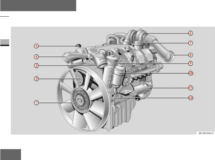
At a glance
OM 501 LA overview
 OM 501 LA overview
1
12

1 Fan
2 Coolant pump
3Charge-air pressure pipe (with flamestart system*) from charge-air cooler
4Charge-air pressure pipe to charge-air cooler
5 Oil filler neck
6 Exhaust gas turbocharger
7 Crankcase ventilation system oil trap
8 Exhaust pipe (with engine brake throttle valve*)
9 Oil filter a Fuel filter
b Starter motor c Dipstick
At a glance
OM 501 LA overview 
13
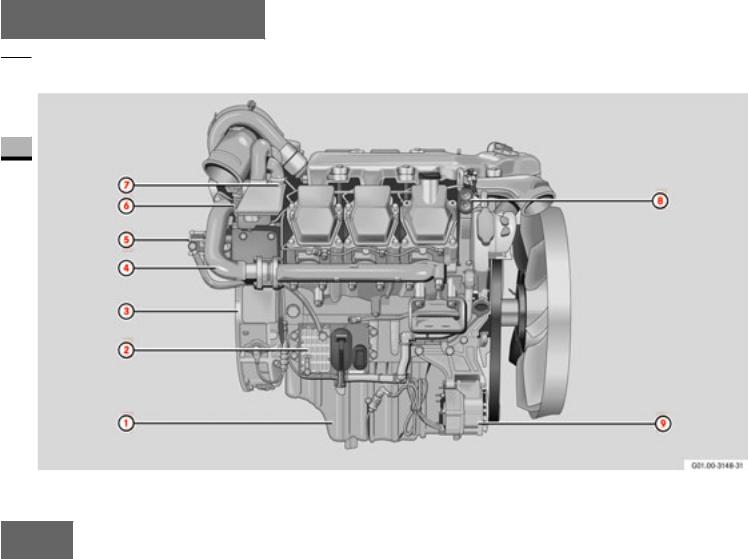
At a glance
 OM 501 LA overview
1
14

1 Oil sump
2 Engine control unit
3 Flywheel housing
4 Exhaust manifold
5Fuel pump (with flange-mounted power-steering pump*)
6 Air compressor*
7Resonator* (only in conjunctio n with air compressor)
8 Start-Stop buttons
9 Alternator
At a glance
OM 501 LA overview 
15
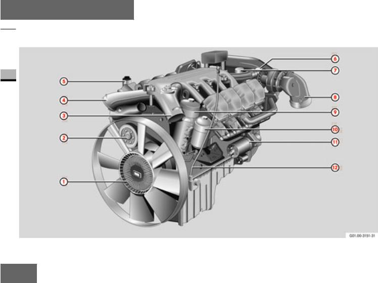
At a glance
OM 502 LA overview
 OM 502 LA overview
1
16

1 Fan
2 Coolant pump
3Charge-air pressure pipe (with flamestart system*) from charge-air cooler
4Charge-air pressure pipe to charge-air cooler
5 Oil filler neck
6 Exhaust gas turbocharger
7 Crankcase ventilation system oil trap
8 Exhaust pipe (with engine brake throttle valve*)
9 Oil filter a Fuel filter
b Starter motor c Dipstick
At a glance
OM 502 LA overview 
17

At a glance
 OM 502 LA overview
1
18
![]()
1 Oil sump
2 Engine control unit
3 Flywheel housing
4 Exhaust manifold
5Fuel pump (with flange-mounted power-steering pump*)
6 Air compressor*
7Resonator* (only in conjunctio n with air compressor)
8 Start-Stop buttons
9 Alternator
At a glance
OM 502 LA overview 
19
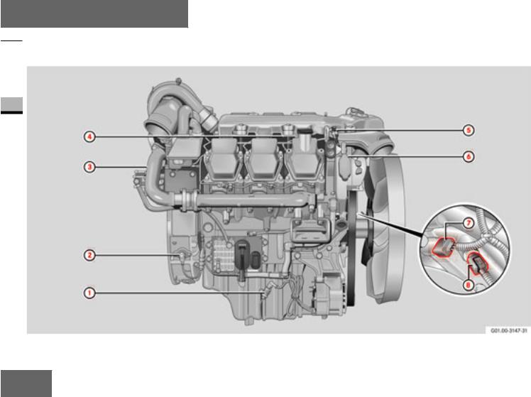
At a glance
Location of sensors
 Location of sensors
1
20

1 Oil level sen sor
2Crankshaft position sensor (on the flywheel)
3Cylinder 1 TDC sensor (on the camshaft sprocket)
4 Fuel temperature sensor
5 Combined charge-air pressure and temperature sensor
6 Coolant temperature sensor
7 Oil pressure sensor
8 Oil temperature sensor
At a glance
Location of sensors 
21
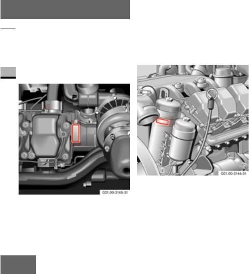
At a glance
Engine plate
 Engine plate
|
Location |
|
|
The engine plate is located on the left-hand |
|
|
1 |
side of the engine, on the engine block af- |
|
ter the last cylinder. |
A second engine plate is mounted on the front of the oil filter casing.
Engine plate, left -hand side of engine, fan end
Engine plate, left-hand side of engine, flywheel end
22
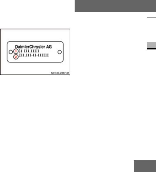
Information on the engine plate
On motor vehicles, the engine plate shows the engine model designation 1and the full engine number 2alon g with the manufacturer’s name.
In addition to this, engines for mobile machines and equipment carry th e engine series designatio n and approval number.
Engine plate
1Engine mo del designation
2Engine number
At a glance
Engine plate 
23

24

Before commissioning
General remarks
Transport /installation
2
25

Before commissioning
General remarks
 General remarks
Type designation
OM 501 L A
|
OM |
Oil engine (diesel |
|
2 |
en gine) |
|
501 |
Engine model1 |
LCharge-air co oling
AExhaust gas turbocharger
1 Engine model 501: 6-cylinder, engine model 502: 8-cylinder
Engine data card |
||
|
Engine data card |
||
The en gine data card (DIN A4 sheet) forms an integral part of the documents belonging to the engine and should always be kept with the Maintenan ce Booklet. It contains details about the engine’s construction , in cluding special equipment features.
The engine data card must be produced for the procurement of genuine parts.
i
The engine data card describes the scope of delivery from the supplying factory; later changes to the scope of delivery are not included on the data card.
Always keep the engine data card with the Maintenance Bo oklet .
26

Description of the engine
The OM 501 LA and OM 502 LA engines are water-cooled 4-stroke direct injection diesel engines.
The 6 or 8 cylinders are arranged in a 90° V and have separate fuel-injection pumps (unit pumps) with a short highpressure fuel injection line to the multihole injection nozzle located centrally in relation to th e combustion chamber. Th e unit
pumps are mounted directly on the crankcase and is driven by the camshaft. Each cylinder has two inlet valves and two exhaust valves.
The OM 501 LA and OM 502 LA engines are equipped with an exhaust gas turbocharger and a charge-air cooler as standard. The engine can be optio nally equipped with an engine brake* (throttle valve and constantly-open throttle valves) and a flame-start system.
Thanks to their fully electronic control system for controlling the injection quantity and injection timing via solenoid valves, these are particularly low-emission engines.
The control system comprises an en gineresident control unit, an engine control (MR) with integrated heat exchanger for cooling by means of the forward fuel flo w and an application-related control unit, a vehicle con trol (FR) or an adaptation mo d- ule (ADM), all interconnected via the Controller Area Network (CAN).
Before commissioning
General remarks 
27
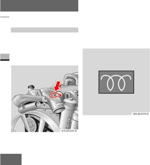
Before commissioning
 General remarks
Flame-start system*
The flame-start system is a cold-start aid for starting at low outside temperatures. It reduces the white smoke emission after the en gine is started. In addition, it reduces the strain on the starter motor and batteries by shortening the startup time.
Fuel can be ignited by a flame heater plug mounted in the charge-air duct intake. The fuel is supplied to the flame heater plug via a solenoid valve with a dosin g jet.
The flame-start system is primed after a preglow time (maximum 20 seconds) which is dependent on the outside temperature. After this time the flame-start system indicator lamp goes out.
Once the engine has started, the flamestart system is supplied with fuel by the engine’s fuel delivery pump.
Flame-start system indicator lamp (example)
Flame-start system
28
![]()
The flame-start system is only operational if the engine is started within 30 seconds of the flame-start system indicator lamp going out.
i
If the flame-start system indicator lamp does not go out after more than 20 seconds, there is a malfunction in the flame-start system.
i
Also observe the «Diesel fuels» ( page 62) and «Coolant»
( page 65) sections when operating the engine at low outside temperatures.
Before commissioning
General remarks 
Engine exhaust brake/constantlyopen throttle valves*
To increase braking power, the engines can be equipped with an engine brake valve on the exhaust gas turbocharger in conjunction with constantly-open throttle valves o n the cylinders.
While the exhaust gas back pressure from the engine brake valve can be used to increase the braking power, the constantlyopen throttle valves cause a pressure reduction in the working cycle (3rd stroke), while compression (2nd stroke) is practically unaffected.
The constantly-open throttle valves are small valves which are integrated in the cylinder head and located on the side opposite the exhaust valve. When open, they form a connection from the combustion chamber to the exhaust port.
Control of the constantly-open throttle valves
29

Before commissioning
 General remarks
When the engine brake is applied*, the constantly-open throttle valves are pressurised with compressed air which opens the valves. At th e same time, the engine brake valve on the exhaust gas turbocharger is closed.
|
2 |
The engine brake* is con trolled by the |
|
drive control unit ( page 33) or the ADM. |
The engine brake* is always inactive below 900 rpm to prevent the engine from stalling. The engine brake* is also automatically deactivated if the position sensor is triggered (e.g. if the accelerator pedal is depressed).
i
In emergency running mode (constant engine speed), the engine brake* can only be activated in overrun mode at a higher engine speed. The engine brake* is automatically deactivated again once the constant engine speed has been reached.
30

Telligent® engine system
The engines have a fully electronic control system, which, in addition to the engine and related sensors, also comprises:
an engine control unit, and
a drive control unit and/or other vehi- cle-specific control units or ADM.
Both are interco nnected via a CAN (Controller Area Network) line which exchanges all the necessary data /information.
The engine control monitors itself as well as the engine. A safety and emergen cyrunning program is selected automatically depending on the malfunctions/ failures which occur ( page 41).
Engine control unit (engine-resident)
The engine control unit is located on the righ t-hand side of the engine.
Engine control unit
Before commissioning
General remarks 
The engine control unit processes data coming from the drive control unit or the ADM, such as the position of the sensor (accelerator pedal position sensor), the engine brake* or engine start/stop, etc.
31

Before commissioning
 General remarks
This data is evaluated along with data from the sensors on the engine, such as those for
charge-air pressure and temperature
coolant temperature
|
2 |
fuel temperature |
|
|
oil pressure |
These parameters are compared with the characteristic diagrams and curves stored in the engine control unit.
Start, duration and amount of injection are calculated from the curves and the unit pumps are controlled accordingly via the so lenoid valves.
Control unit type plate
1 Data record
2 Certification no.
3 Engine number
4 Equipment code
i
All the information on the con trol unit type plate is required to obtain a replacement engine contro l unit .
32

FR (drive control) unit or ADM
(appliance-resident)
The engine can be adapted to meet the various application-specific requirements by means of the FR (drive control) unit or adaptation module (ADM).
Drive control unit
The FR (drive co ntrol) unit or the ADM unit stores data for specific applications, such as idling speed, maximum working speed and speed limitation.
The FR (drive control) unit and the ADM receive data from the
operato r (position of setpoint value sensor, engine start/ stop)
engine brake switch*
other systems (e.g. acceleration skid contro l)
engine control unit (e.g. o il pressure and coolant temperature)
From this data, the instructions for the MR (engine control) unit are computed and transmitted to it via the CAN line.
The drive control unit and the ADM control various displays, e.g. the electronics warn — ing lamp, the engine brake* and the con- stantly-open chokes*.
Before commissioning
General remarks 
33

Before commissioning
 General remarks
If the Telligent® engine system detects a fault, this is stored as a fault code in the control units and can be read using the appropriate diagnostic testers (STAR DIAGNOSIS or Minidiag 2). In addition, the electronics warning lamp is switched on.
You can connect the diagnostic testers to the appliance-resident, 14-pin diagnostic socket. You can read both the malfunction memory and the stored engine data with these testers.
Informatio n about the diagnostic testers is available at any Mercedes-Benz Service Centre.
Diagnostic socket
Organisational measures
|
Risk of accident and injury |
G |
Before operating the engine, please read these Operating Instructions and other authoritative documentation, such as the Operating Instructions for the vehicle or the machine the engine is installed in.
You could otherwise fail to recognise dangers and could injure yourself or others.
The Operating Instructions and Maintenance Booklet must be given to the personnel responsible for operating the engine or carrying out work on the en gine, and should be kept where the engine is used in an easily accessible place.
Personnel must be instructed in how to work on the engine using these Operating Instructions. In particular, the safety notes must be explained. This is especially important for personnel who only work on the engine occasionally.
In addition to these Operating Instructions, the country-specific legal and all other binding regulations for accident prevention and protection of the environmen t must be observed.
34

Transport /installation
Transport
|
Risk of accident and injury |
G |
The engine can tear loose and cause injury to persons by overturning or falling.
Only lift the engine by the appropriate lifting points on the engine.
Only use transport equipment which has been approved for use by DaimlerChrysler.
Only lift and transport the engine in its installation position: Note that the engine must not be tilted more than 30° when it is being hoisted in or out of equipment or vehicles.
Before commissioning
Transport/installation
|
Suspension fixture, flywheel end (illustrat- |
Suspension fixture, belt side |
ed: OM 501 LA)
i
The flywheel end suspension fixture on the OM 502 LA is located behind the turbocharger intake pipe.
35
 Loading…
Руководство по эксплуатации двигателей Mercedes-Benz OM501LA и OM502LA Скачать Бесплатно
Скачать1,28 Мб
ПОКАЗАТЬ ВСЕСВЕРНУТЬ
Поиск товаров
Группа компании “RICHTONE” всегда готова предложить Вам запасные части для техники Mercedes в нашем каталоге.
Для того что бы СКАЧАТЬ данную инструкцию напишите нам на электронную почту rceshopmanuals@gmail.com
подождите загрузки книги
Часть 1
Руководство по ремонту и эксплуатации Mercedes Actros III с 2008 по 2011 год выпуска.
Издательство: Диез
Тип бумаги: газетная
Кол-во страниц: 496
Переплет: твердый
Цветность: черно-белая
Вес: 1
Формат: 148 Х 210
Тип двигателя: ОМ 501 LA V6 / V8
Цена: 998 р.
Старая цена: 1067 р.
3 человека сейчас также
интересуются данным товаром
В данном руководстве приведена информация по ремонту и эксплуатации грузовиков Mercedes Actros с дизельными двигателями ОМ 501 LA V6 / V8
Содержание
Эксплуатация и техобслуживание
Рабочие жидкости, масла и смазки
Рабочие технические характеристики автомобиля
Идентификационные номера автомобиля
Приобретение запасных частей
Безопасность
Вывешивание автомобиля на подъемнике или домкрате
Техническое обслуживание – информация общего характера
Техническое обслуживание – отдельные плановые операции
Отдельные операции техобслуживания, непосредственно влияющие на безопасность
Система управления
Руководство по ремонту
Двигатель
Топливная система
Система охлаждения
Система выпуска отработавших газов, моторный тормоз «Заслонка на выпуске» и система впрыска раствора мочевины AdBlue (BlueTec4 и BlueTec5)
Электрооборудование двигателя
Сцепление
Механизм отбора мощности
Коробка переключения передач (КПП)
Карданная передача
Задний мост
Передний мост
Подвеска передних колес
Подвеска задних колес
затяжки резьбовых соединений
Рулевое управление
Тормозная система
Электросхемы
Оставить отзыв
Ваше Имя:
Ваш отзыв:
Введите код, указанный на картинке:
Эксплуатация и техобслуживание
Первый задний мост моделей с двумя задними мостами – замена масла
Внимание!
Перед сливом масла трансмиссия должна быть прогрета.
- Очистите место вокруг пробок (1 и 2).
- Вывернув все пробки, слейте масло в подставленную посуду.
- Слив все масло, заверните пробку (2) сливного отверстия и затяните ее моментом 120 Нм.

Замена масла в первом заднем мосту моделей с двумя задними мостами
- Залейте в задний мост трансмиссионное масло из Перечня DB 235.00, 235.06, 235.08 или 235.20: – в мосты 748.272/273/274/275 и моделей 930.182/183, 932.18, 934.182 с диаметром ведомой шестерни 300 мм (код ZP0/ZP1) можно заливать масло только из Перечня DB 235.08.
– в мосты 748.26/27/7 моделей 374.5/602/651/655/6 82/685 с диаметром ведомой шестерни 300 мм можно заливать масло только из Перечня DB 235.20.
– в мосты 748.263/273/275 тяжелых грузовиков моделей 934, SLT (с индексом HD7) с диаметром ведомой шестерни 300 мм можно заливать масло только из Перечня DB 235.08. – в мосты 748.26/27/7 моделей 374.5/602/651/655/ 682/685 с диаметром ведомой шестерни 233 мм можно заливать масло только из Перечня DB 235.20.
- Заливайте масло по нижний край заливного отверстия. В картер помещается 1,0 л масла.
- Залив масло и проверив его уровень, заверните пробку (1) заливного отверстия редуктора и затяните ее:
– пробку с резьбой M24 – моментом 120 Нм;
– пробку с резьбой M45 в литую крышку – моментом 350 Нм;
– пробку с резьбой M45 в крышку из штампованного листового металла – моментом 150 Нм.
- На моделях с кодом JW5 (система контроля техобслуживания Telligent) с помощью прибора Star Diagnosis откорректируйте установки качества залитого масла (если требуется).
Топливный фильтр тонкой очистки – замена фильтрующего элемента
- Для снятия избыточного давления в топливном баке откройте пробку его заливной горловины.
- Используя подходящую головку с воротком, отверните крышку (1) корпуса фильтра, но не снимайте ее – дайте топливу стечь в бак.
- Снимите крышку (1) вместе с фильтрующим элементом (3) и замените его.
- Заменив уплотнительное кольцо (2), смазав его силиконовой смазкой, заверните крышку с фильтрующим элементом и затяните ее моментом 25 Нм.

Топливный фильтр тонкой очистки: двигатели 541.9, 542.9
- Закройте пробку топливного бака. Затянув стояночный тормоз и включив нейтраль в трансмиссии, проворачивайте двигатель стартером в течение примерно одной минуты – топливная система должна прокачаться автоматически.Если двигатель после этого не пускается или, пустившись, глохнет, прокачайте топливную систему, как описано далее.
- Запустив двигатель, убедитесь в отсутствии протечек топлива.
Другие книги по ремонту и обслуживанию автомобилей Mercedes:
- руководство по ремонту Mercedes Sprinter
- книги по ремонту Mercedes Axor
- инструкция по эксплуатации Mercedes MB 100D
Автомобильная литература
