
Powersystems • Industrial Engines
Maintenance and Repair
Series 457, 500 and 900
Advanced Training
As at 04/03
Powersystems • Industrial Engines
Maintenance and Repair Series 457,

This document is provided for training purposes only and is not subject to the normal updates.
Printed in Germany
ã 2003 Copyright DaimlerChrysler AG
Herausgeber: Global Training
This documentation and all its constituent parts are subject to copyright. Any reproduction or re-
use requires written permission from DaimlerChrysler AG in advance. This especially applies to
any duplication, dissemination, editing, translation, and microfilming of this documentation, or
storage and/or processing on electronic systems, databases and online services.
Note:
The term «employee» always refers to both
male and female staff.
1511 1209 02 — 1
st
edition 04.03 236 As at 04/03

05/03 Powersystems • Industrial Engines Maintenance and Repair Series 457, 500 and 900 Advanced Training
Content
I1
Content 07.05.2003
Title Side
Welcome ……………………………………………………………………………………………………………………………………………………………………………………………………………………..1
Engine model series OM 457 LA……………………………………………………………………………………..………………………………………………………………………………………………2
Engine OM 457 LA ………………………………………………………………………………………………………………………………………………………………………………………………………..4
Series 457<>Cylinder head…………………………………………………………………………………………………………………………………………………………………………………………..11
Series 457<>Cylinder head — cross section (transverse and longitudinal) ………………………………………………..…………………………………………………………………………12
Series 457 LA<>Port assignments in the cylinder head gasket …………………………………………………………..…………………………………………………………………………….13
Series 457<>Cylinder head bolts — tightening instructions…………………………………………………………….………………………………………………………………………………….14
Series 457<>Setting valve play …………………………………………………………………………………….………………………………………………………………………………………………16
Series 457<>Removing/installing the nozzle holder combination……………………………………………………………………………………………………………………………………..19
Series 457<>Valve cover and valve cover gasket ……………………………………………………………………………………………………………………………………………………………25
Series 457<>Oil pan ……………………………………………………………………………………………………………………………………………………………………………………………………26
Series 457<>Pump-line-nozzle injection system ……………………………………………………………………….…………………………………………………………………………………….27
Series 457<>Removing/installing the MR/PLD unit pump……………………………………………………………………………………………………………………………………………….28
Series 457<>Pistons……………………………………………………………………………………………………………………………………………………………………………………………………35
Series 457<>Lubrication schematic diagram …………………………………………………………………………..……………………………………………………………………………………..36
Series 457<>Oil spray nozzle………………………………………………………………………………………………………………………………………………………………………………………..38
Series 457<>Crankcase and cylinder liner ……………………………………………………………………………………………………………………………………………………………………..39
Series 457<>Camshaft ……………………………………………………………………………………………..…………………………………………………………………………………………………40

05/03 Powersystems • Industrial Engines Maintenance and Repair Series 457, 500 and 900 Advanced Training
Content
I2
Series 457<>Fuel system …………………………………………………………………………………………..………………………………………………………………………………………………..42
Series 457<>Fuel pump…………………………………………………………………………………………….…………………………………………………………………………………………………45
Series 457<>Fuel prefilter with heated water separator ……………………………………………………………….………………………………………………………………………………….46
Series 457<>Planetary drive starter ………………………………………………………………………………..…………………………………………………………………………………………….48
Series 457<>Fan drive and fan systems…………………………………………………………………………………………………………………………………………………………………………50
Series 457<>Air compressor ………………………………………………………………………………………..………………………………………………………………………………………………52
Series 457<>Turbocharger BR S400 …………………………………………………………………………………..…………………………………………………………………………………………53
Series 457<>Engine oil and filter change ……………………………………………………………………………………………………………………………………………………………………….54
Series 457<>Replacing the fuel filter …………………………………………………………………………………………………………………………………………………………………………….56
Series 457<>Fuel filter with water separator — replacing the filter element…………………………………………….…………………………………………………………………………..58
Series 457<>Air cleaner, engine coolant service ……………………………………………………………………..……………………………………………………………………………………..60
Series 500<>Engine models …………………………………………………………………………………………………………………………………………………………………………………………62
Series 500<>Technical features …………………………………………………………………………………….……………………………………………………………………………………………..64
Series 500<>Cylinder head — port assignment ………………………………………………………………………………………………………………………………………………………………..70
Series 500<>Cylinder head…………………………………………………………………………………………………………………………………………………………………………………………..71
Series 500<>Cylinder head mounting ……………………………………………………………………………………………………………………………………………………………………………73
Series 500<>Cylinder head gasket …………………………………………………………………………………..……………………………………………………………………………………………74
Series 500<>EURO 2 and EURO 3 cylinder heads compared ………………………………………………………………..………………………………………………………………………….75
Series 500<>Valve assembly………………………………………………………………………………………..………………………………………………………………………………………………77
Series 500<>Pump-line-nozzle injection system (PLD) ………………………………………………………………….…………………………………………………………………………………83
Series 500<>Removing/installing the MR/PLD unit pump……………………………………………………………………………………………………………………………………………….91
Series 500<>EURO 2 and EURO 3 pistons ………………………………………………………………………………………………………………………………………………………………….. 101

05/03 Powersystems • Industrial Engines Maintenance and Repair Series 457, 500 and 900 Advanced Training
Content
I3
Series 500<>Connecting rod ………………………………………………………………………………………..…………………………………………………………………………………………… 102
Series 500<>Crankcase…………………………………………………………………………………………….……………………………………………………………………………………………… 103
Series 500<>Cylinder liners……………………………………………………………………………………….……………………………………………………………………………………………… 104
Series 500<>EURO 2 and EURO 3 cylinder liners compared ……………………………………………………………….………………………………………………………………………… 107
Series 500<>Crankcase ventilation system ………………………………………………………………………………………………………………………………………………………………… 108
Series 500<>Fuel system …………………………………………………………………………………………..…………………………………………………………………………………………….. 112
Series 500<>Oil cooler and oil filter housing – component locations……………………………………………………………………………………………………………………………… 124
Series 500<>Oil circuit …………………………………………………………………………………………..………………………………………………………………………………………………… 128
Series 500<>Engine oil system……………………………………………………………………………………..…………………………………………………………………………………………… 129
Series 500<>Oil spray nozzle…………………………………………………………………………………………………………………………………………………………………………………….. 130
Series 500<>Water guide …………………………………………………………………………………………..…………………………………………………………………………………………….. 134
Series 500<>Thermostat location………………………………………………………………………………………………………………………………………………………………………………. 136
Series 500<>Supercharging system and charge air ducting ………………………………………………………………………………………………………………………………………….. 137
Series 500<>Engine oil and filter change ……………………………………………………………………………………………………………………………………………………………………. 140
Series 500<>Cleaning the fuel prefilter / filter insert …………………………………………………………………………………………………………………………………………………… 144
Series 500<>-Fuel prefilter with water separator — replacing the filter element ……………………………………………………………………………………………………………….. 146
Series 500<>Replacing the oil separator insert …………………………………………………………………………………………………………………………………………………………… 148
Series 500<>Replacing the fuel filter — air cleaner — coolant ………………………………………………………………………………………………………………………………………….. 150
Engines OM 904 and 906 …………………………………………………………………………………………………………………………………………………………………………………………. 152
Engine series 900 ………………………………………………………………………………………………..………………………………………………………………………………………………….. 153
Series 900<>Technical features …………………………………………………………………………………….………………………………………………………………………………………….. 156
Series 900<>Port assignments in the cylinder head gasket ……………………………………………………………..…………………………………………………………………………… 159

05/03 Powersystems • Industrial Engines Maintenance and Repair Series 457, 500 and 900 Advanced Training
Content
I4
Series 900<>Tightening instructions for cylinder head bolts …………………………………………………………..…………………………………………………………………………….. 160
Series 900<>Valve control………………………………………………………………………………………………………………………………………………………………………………………… 162
Series 900<>Setting valve play …………………………………………………………………………………….…………………………………………………………………………………………… 164
Series 900<>Pump-line-nozzle injection system (PLD) ………………………………………………………………….……………………………………………………………………………… 167
Series 900<>Crankcase…………………………………………………………………………………………….……………………………………………………………………………………………… 185
Series 900<>Ölspritzdüsen — Unterschiede …………………………………………………………………………………………………………………………………………………………………. 188
Series 900<>Pistons and piston rings ……………………………………………………………………………….……………………………………………………………………………………….. 189
Series 900<>Connecting rod ………………………………………………………………………………………..…………………………………………………………………………………………… 190
Series 900<>Pistons and connecting rod — modifications ……………………………………………………………………………………………………………………………………………… 191
Series 900<>Engine oil circuit …………………………………………………………………………………….…………………………………………………………………………………………….. 192
Series 900<>Removing/installing the oil pan ……………………………………………………………………………………………………………………………………………………………… 196
Series 900<>Fuel system …………………………………………………………………………………………..…………………………………………………………………………………………….. 200
Series 900<>Supercharging system and charge air ducting ………………………………………………………………………………………………………………………………………….. 212
Series 900<>Removing/installing the coolant thermostatic control ………………………………………………………………………………………………………………………………. 216
Series 900<>Engine oil and filter change ……………………………………………………………………………………………………………………………………………………………………. 218
Series 900<>Cleaning the fuel prefilter — filter insert ……………………………………………………………………………………………………………………………………………………. 221
Series 900<>Fuel prefilter with water separator — replacing the filter element ………………………………………….…………………………………………………………………….. 223
Series 900<>Replacing the fuel filter — air cleaner — coolant ………………………………………………………………………………………………………………………………………….. 226
05/03 Powersystems • Industrial Engines Maintenance and Repair Series 457, 500 and 900 Advanced Training
Welcome
1
Welcome 07.05.2003
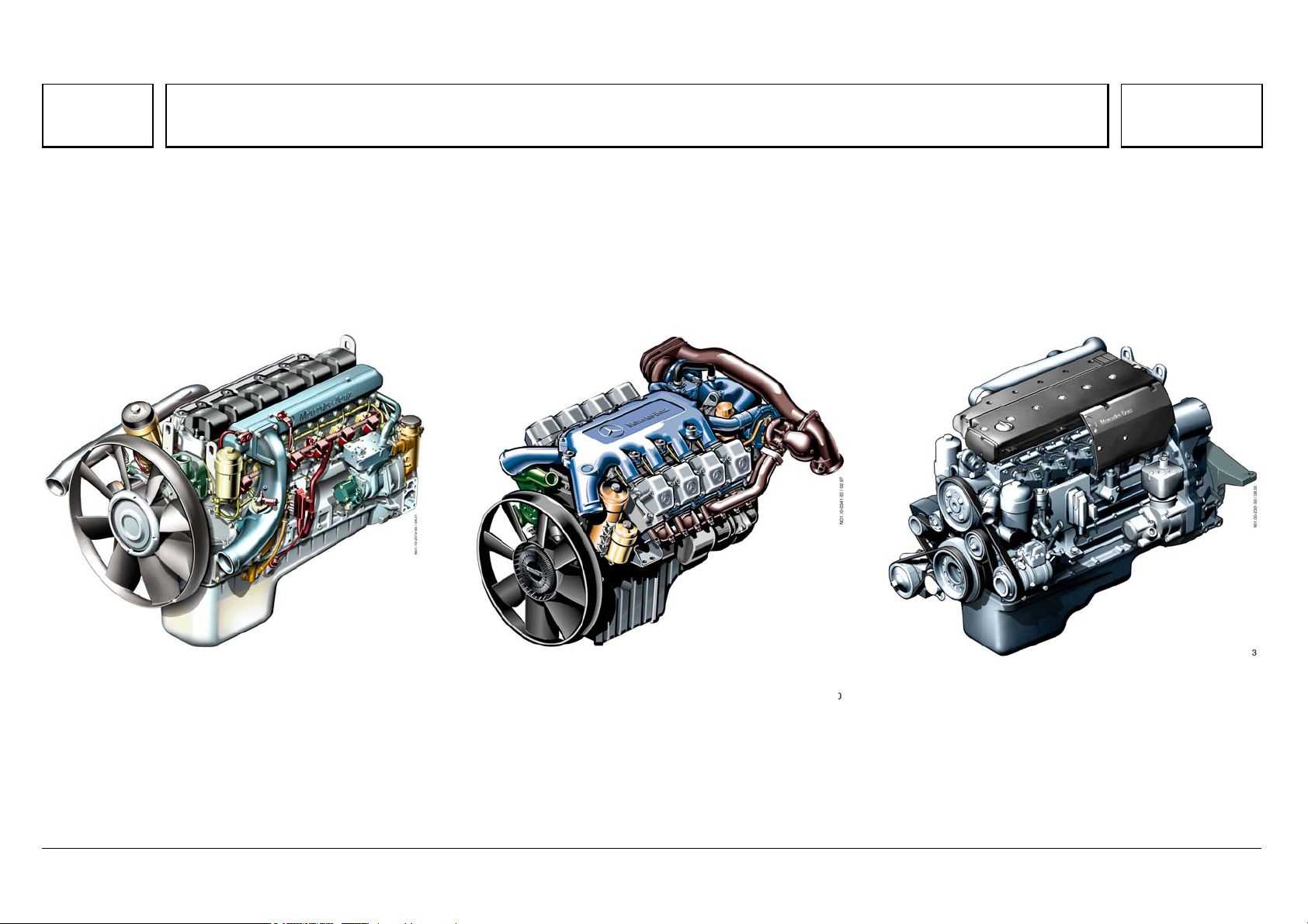
OM 457 LA OM 502 LA OM 906 LA
N01.10-2073-50 N01.10-0341-50 N01.00-2301-50
05/03 Powersystems • Industrial Engines Maintenance and Repair Series 457, 500 and 900 Advanced Training
Series 500<>Engine models
62
Series 500<>Engine models 07.05.2003
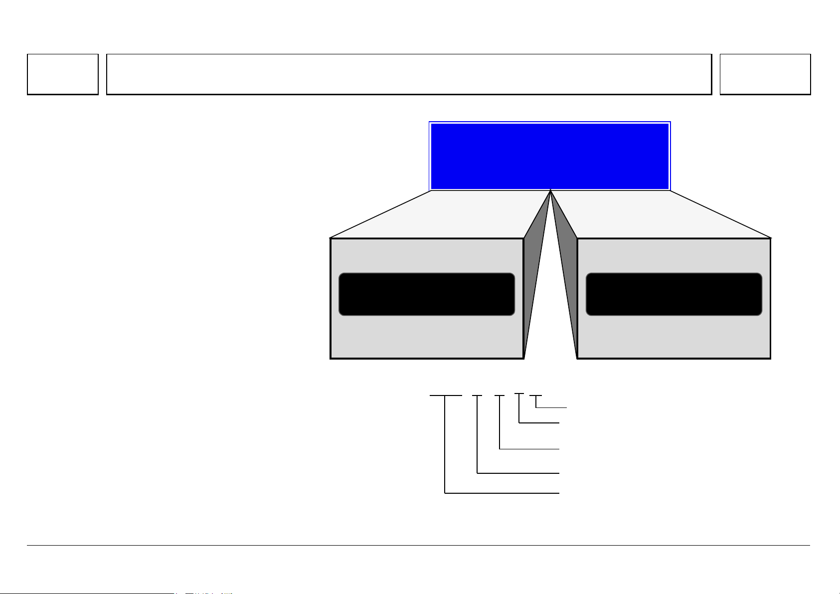
The 500 engine model series is future-ready, and
comes in V6 and V8 cylinder variants with 2 litre
swept volume per cylinder.
The sales designation is formed in the same way
as the 400 model series:
6-cylinder engine: OM 501 LA
8-cylinder engine: OM 502 LA
At the same time, the OM 457 LA engine was
developed with the same basic design as the V-
engines.
The Series 2000 V12 and V16 MTU engines are
derived from the BR 500, and are intended for
industrial applications.
Model series 500
6
OM 501 L
8
OM 502 L
H
= 12l V
H
= 16l
OM 501 LA
OM 501 LA
Turbocharger
Char
e air cooler
1=6-cylinder V-engine
2=8-cylinder V-engine
Model series 500
Diesel engine
05/03 Powersystems • Industrial Engines Maintenance and Repair Series 457, 500 and 900 Advanced Training
Series 500<>Engine models
63
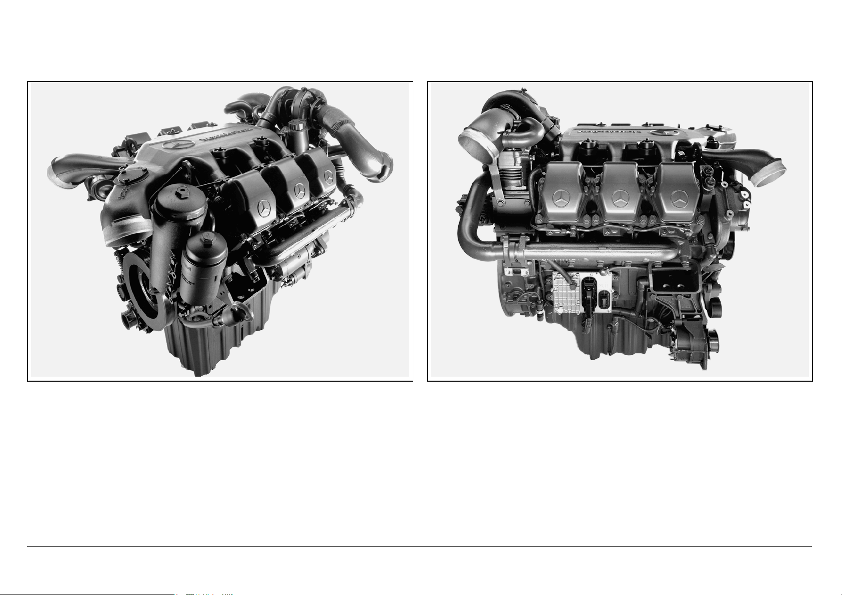
N01.10-2026-11 N01.10-2028-11
The development of the 500 series encapsulates all the knowledge and experience gained from the 1 million V-engines manufactured since 1969, when
production of the OM 403 V10 engine began.

05/03 Powersystems • Industrial Engines Maintenance and Repair Series 457, 500 and 900 Advanced Training
Series 500<>Technical features
64
Series 500<>Technical features 07.05.2003
Þ Outstanding power output and torque characteristics over the whole
rpm range
Þ Dynamic start-off characteristics and pulling power
Þ Attractive power/weight ratio
Þ Low fuel consumption
Þ Enormous potential: the V6 engines meet the requirements of the highly
popular 400 HP Class
Þ High-pressure direct injection, pump-line-nozzle system with peak
pressures up to 1,800 bar.
Þ Electronic engine control (MR) with electronic system fixed to the
engine, and extensive engine protection functions
Þ Direct injection with centrally positioned 6-hole injection nozzle.
Þ 4-valve technology
Þ Useful engine brake rpm well over rated rpm, up to 2400 rpm
Þ Meets the emission legislation of EURO 3 and EUROMOT/EPA Level 2
Þ Turbocharger with charge air cooling
Þ V8 with 2 turbochargers
Þ Viscous fan clutch, electromagnetic fan clutch and high-speed fan
drive on the most powerful engines
Þ Rated engine speed 1,800 rpm or 2000 rpm
Þ Low maintenance requirement
Þ Long maintenance intervals
Þ Engine oil and fuel filter located at the front, for easy maintenance
Þ Maintenance-free belt drive
Þ Can run on FAME / RME (rape methyl ester) or biodiesel, and engine oil
changes are halved
Þ High reliability and long runtime
Þ Low number of component variants, as many parts are the same on both
6 and 8 cylinder engines
Þ Rear engine power take-off ex works

05/03 Powersystems • Industrial Engines Maintenance and Repair Series 457, 500 and 900 Advanced Training
Series 500<>Technical features
65

05/03 Powersystems • Industrial Engines Maintenance and Repair Series 457, 500 and 900 Advanced Training
Series 500<>Technical features
66
Overview of BR 500 engines with EURO 3 certification
Engine
model
No. of
cylinders/
layout
Output (rpm) Torque (rpm) Cylinder bore Cylinder
stroke
Displace
ment
Dimensions
L x W x H
Weight Power/weight
ratio
[kW/HP (at rpm)] [Nm (at rpm)] [mm] [mm] [l] [mm] [kg] [kg/kW]
OM 501 LA 6 Cyl./V 230/313 (1800) 1530 (1080) 130 150 11.95 1190x1020x1130 885 3.85
OM 501 LA 6 Cyl./V 260/354 (1800) 1730 (1080) 130 150 11.95 1190x1020x1130 885 3.40
OM 501 LA 6 Cyl./V 290/394 (1800) 1850 (1080) 130 150 11.95 1190x1020x1130 885 3.05
OM 501 LA 6 Cyl./V 300/408 (2000) 1900 (1080) 130 150 11.95 1190x1020x1130 885 2.95
OM 501 LA 6 Cyl./V 315/428 (1800) 2000 (1080) 130 150 11.95 1190x1020x1130 885 2.81
OM 502 LA 8 Cyl./V 320/435 (2000) 1900 (1080) 130 150 15.93 1530x1195x1080 1125 3.52
OM 502 LA 8 Cyl./V 350/476 (2000) 2100 (1080) 130 150 15.93 1530x1195x1080 1125 3.21
OM 502 LA 8 Cyl./V 350/476 (1800) 2300 (10809 130 150 15.93 1530x1195x1080 1125 3.21
OM 502 LA 8 Cyl./V 370/503 (2000) 2300 (1080) 130 150 15.93 1530x1195x1080 1125 3.04
OM 502 LA 8 Cyl./V 390/530 (1800) 2400 (1080) 130 150 15.93 1530x1195x1080 1125 2.88
OM 502 LA 8 Cyl./V 420/571 (1800) 2700 (1080) 130 150 15.93 1530x1195x1080 1125 2.68

05/03 Powersystems • Industrial Engines Maintenance and Repair Series 457, 500 and 900 Advanced Training
Series 500<>Technical features
67
Overview of BR 500 engines with EUROMOT/EPA Level 2 certification
Engine
model
No. of
cylinders/
layout
Output (rpm) Torque (rpm) Cylinder bore Cylinder
stroke
Displace
ment
Dimensions
L x W x H
Weight Power/weight
ratio
[kW/HP (at rpm)] [Nm (at rpm)] [mm] [mm] [l] [mm] [kg] [kg/kW]
OM 501 LA 6 Cyl./V 230/313 (1800) 1530 (1080) 130 150 11.95 1190x1020x1130 885 3.85
OM 501 LA 6 Cyl./V 260/354 (1800) 1730 (1080) 130 150 11.95 1190x1020x1130 885 3.40
OM 501 LA 6 Cyl./V 290/394 (1800) 1850 (1080) 130 150 11.95 1190x1020x1130 885 3.05
OM 501 LA 6 Cyl./V 315/428 (1800) 2000 (1080) 130 150 11.95 1190x1020x1130 885 2.81
OM 502 LA 8 Cyl./V 330/449 (1800) 2150 (1200) 130 150 15.93 1530x1195x1080 1125 3.40
OM 502 LA 8 Cyl./V 350/476 (1800) 2300 (1200) 130 150 15.93 1530x1195x1080 1125 3.21
OM 502 LA 8 Cyl./V 350/476 (2000) 2100 (1200) 130 150 15.93 1530x1195x1080 1125 3.21
OM 502 LA 8 Cyl./V 380/517 (1800) 2400 (1200) 130 150 15.93 1530x1195x1080 1125 2.96
OM 502 LA 8 Cyl./V 420/571 (1800) 2700 (1200) 130 150 15.93 1530x1195x1080 1125 2.68
OM 502 LA 8 Cyl./V 448/609 (1800) 2700 (1200) 130 150 15.93 1530x1195x1080 1125 2.51
05/03 Powersystems • Industrial Engines Maintenance and Repair Series 457, 500 and 900 Advanced Training
Series 500<>Technical features
68
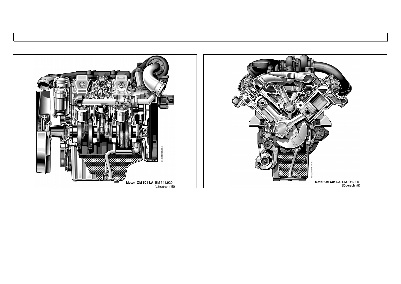
Engine OM 501 LA in cross section
N01.00-2009-50 N01.00-2010-50
05/03 Powersystems • Industrial Engines Maintenance and Repair Series 457, 500 and 900 Advanced Training
Series 500<>Technical features
69
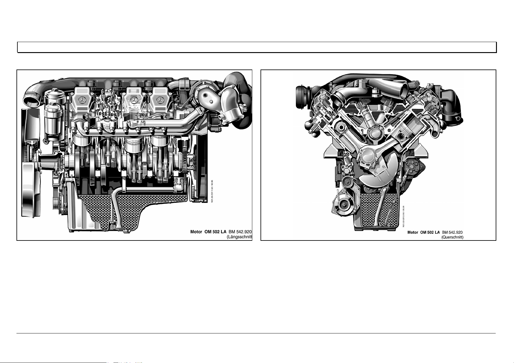
Engine OM 502 LA in cross section
N01.00-2011-50 N01.00-2012-50
05/03 Powersystems • Industrial Engines Maintenance and Repair Series 457, 500 and 900 Advanced Training
Series 500<>Cylinder head — port assignment
70
Series 500<>Cylinder head — port assignment 07.05.2003
Port assignment
A Coolant
BBolts
CPressure oil
D Oil return
E Plunger, oil return
N01.30-2024-12
E
A
E
B
B
D
B
A
B
A
B
C
05/03 Powersystems • Industrial Engines Maintenance and Repair Series 457, 500 and 900 Advanced Training
Series 500<>Cylinder head
71
Series 500<>Cylinder head 07.05.2003
The individual cylinder heads are made of high-quality molybdenum/cast iron alloy. Each has four stretch-
thread bolts (M18x2), with which it is bolted to the crankcase.
The optimal position for the injection nozzle is the vertical position at the center of the combustion
chamber.
This ideal arrangement can only be achieved by using multi-valve technology.
This consists in arranging the valves in pairs (2 intake, 2 exhaust) around the injection nozzle.
A fifth valve is required for the constant throttle or the decompression valve/engine brake.
In both cases, these are linked to the exhaust port through an exactly adjusted hole.
N01.30-2025-02
05/03 Powersystems • Industrial Engines Maintenance and Repair Series 457, 500 and 900 Advanced Training
Series 500<>Cylinder head
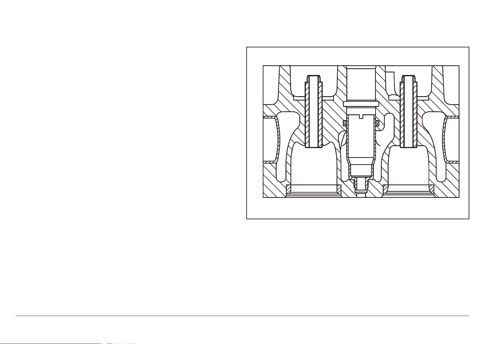
72
The high-temperature, wear-resistant valve seat rings are inserted deep-frozen
into the floor panel.
The nozzle holder is inserted in a protective sleeve, which is washed around
by coolant and thus individually cooled.
The nozzle protective sleeve is sealed by an O-ring against coolant escape,
and by the thread and face against gas escape.
N07.03-2035-11
05/03 Powersystems • Industrial Engines Maintenance and Repair Series 457, 500 and 900 Advanced Training
Series 500<>Cylinder head mounting
73
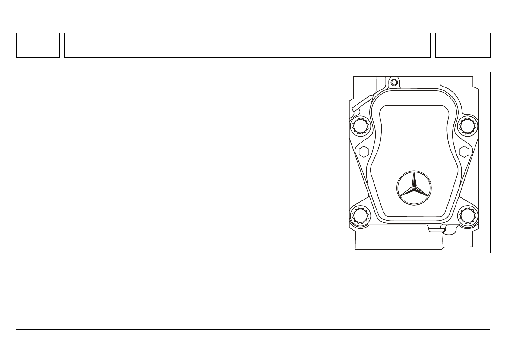
Series 500<>Cylinder head mounting 07.05.2003
The cylinder head is tightened in 6 stages.
The cylinder head bolts do not require
retightening.
Step 1 10 Nm
Step 2 50 Nm
Step 3 100 Nm
Step 4 200 Nm
Step 5 90 °
Step 6 90 °
1 L T 212 mm
W01.30-0009-02 W01.30-0010-06
05/03 Powersystems • Industrial Engines Maintenance and Repair Series 457, 500 and 900 Advanced Training
Series 500<>Cylinder head gasket
74
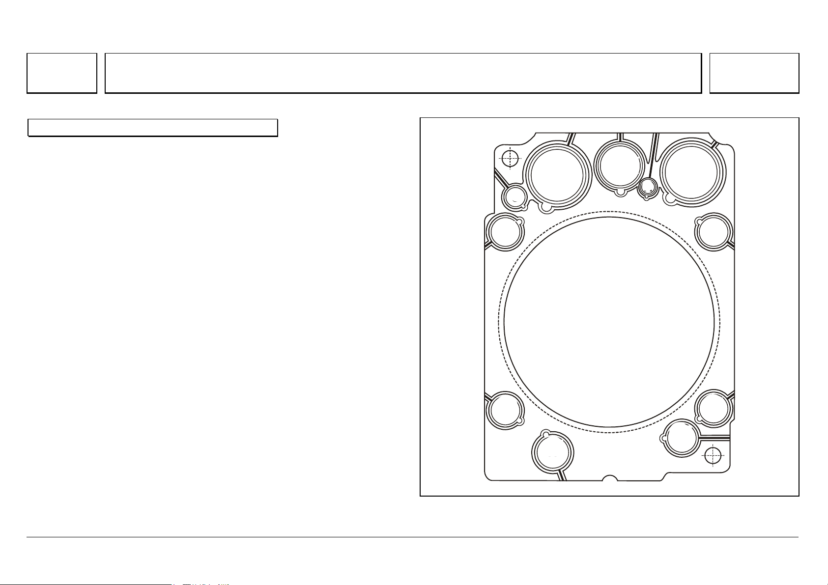
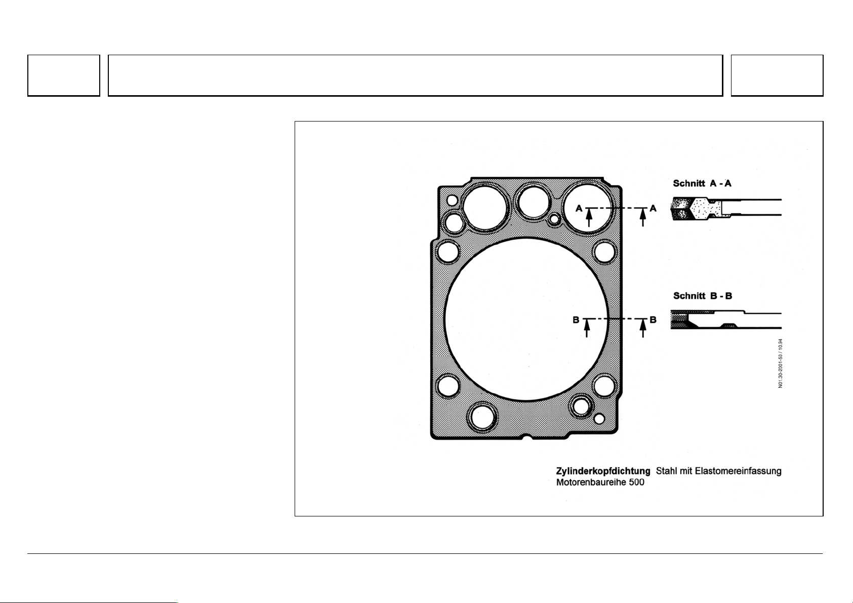
Series 500<>Cylinder head gasket 07.05.2003
Each cylinder head has a stainless steel insert
gasket with scorched elastomer binding, which
does not require retightening.
N01.30-2001-50
05/03 Powersystems • Industrial Engines Maintenance and Repair Series 457, 500 and 900 Advanced Training
Series 500<>EURO 2 and EURO 3 cylinder heads compared
75
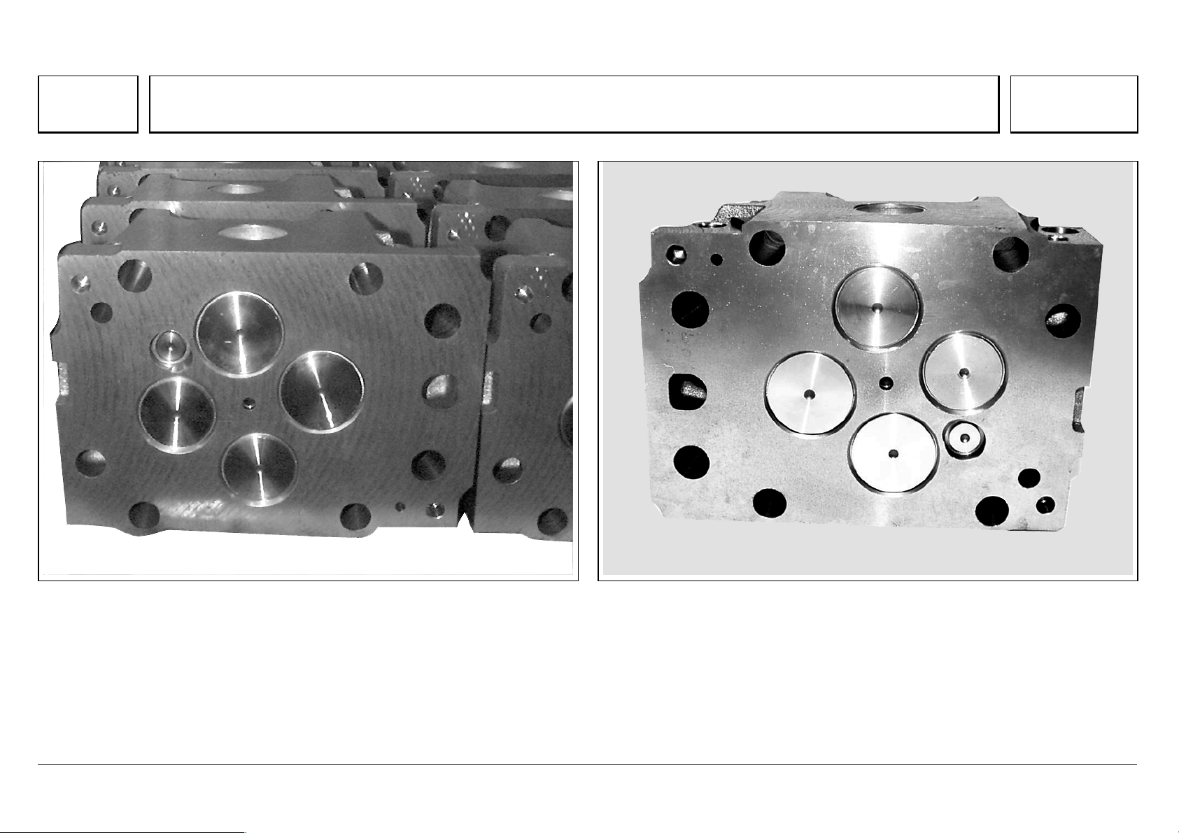
Series 500<>EURO 2 and EURO 3 cylinder heads compared 07.05.2003
Cylinder head old version, as of 04/99
N01.30-2065-11
Cylinder head, Euro 3 version
N01.30-2064-11
In the previous Euro 2 version, the cover surfaces were milled.
Since 2000, as part of the «Euro 3» package of measures, the cylinder head
surfaces are turned, to a specific surface quality.
Since 06/2000, this also applies to all Euro 2 V8 and 315 kW V6 engines,
and from January 2001 to all other V6 engines.
The new cylinder heads should be ground to a minimum height of 113.5 mm,
by face grinding only. The surface quality (peak-to-valley height and
corrugation depth) is to be observed in all cases.

05/03 Powersystems • Industrial Engines Maintenance and Repair Series 457, 500 and 900 Advanced Training
Series 500<>EURO 2 and EURO 3 cylinder heads compared
76
05/03 Powersystems • Industrial Engines Maintenance and Repair Series 457, 500 and 900 Advanced Training
Series 500<>Valve assembly
77
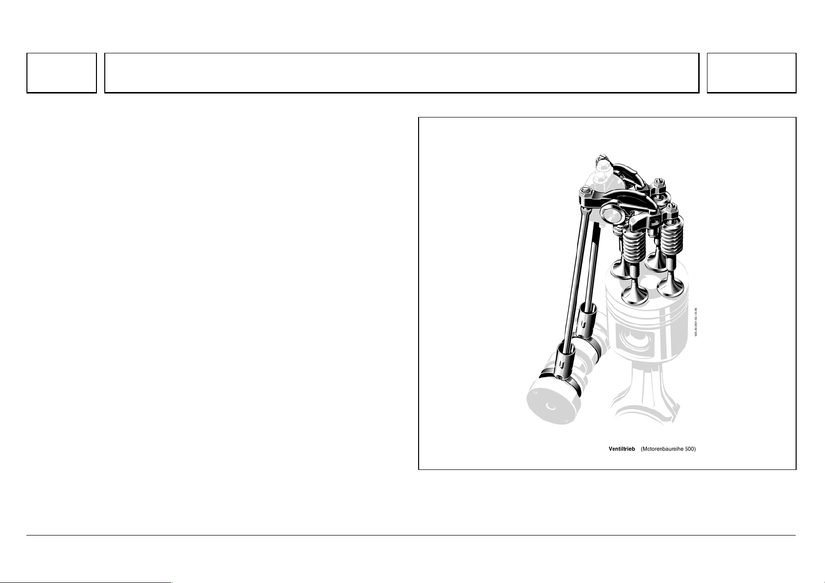
Series 500<>Valve assembly 07.05.2003
Gas exchange is improved by 4-valve technology, thus contributing
considerably to lower fuel consumption with lower emissions.
The intake and exhaust valves are controlled by means of roller tappets, push
rods and intake and exhaust rocker arms which are set in a groove in the
crankcase with a sliding block, and which operate the intake/exhaust valve
pairs through a valve bridge.
The rocker arm spindle complete with preassembled rocker arms and rocker
arm bearing bracket is bolted to the cylinder head.
To keep wear in the whole valve assembly to a minimum throughout its
lifetime, the contact surfaces of the valve, valve bridge, the rocker arm thumb,
the upset ball socket of the push rod, and the ball head of the adjusting
screw, are induction hardened. This is to allow them to support the actuation
forces of the high-temperature valve springs, and the effects of inertial forces
and cylinder pressures.
N05.30-2001-50
05/03 Powersystems • Industrial Engines Maintenance and Repair Series 457, 500 and 900 Advanced Training
Series 500<>Valve assembly
78
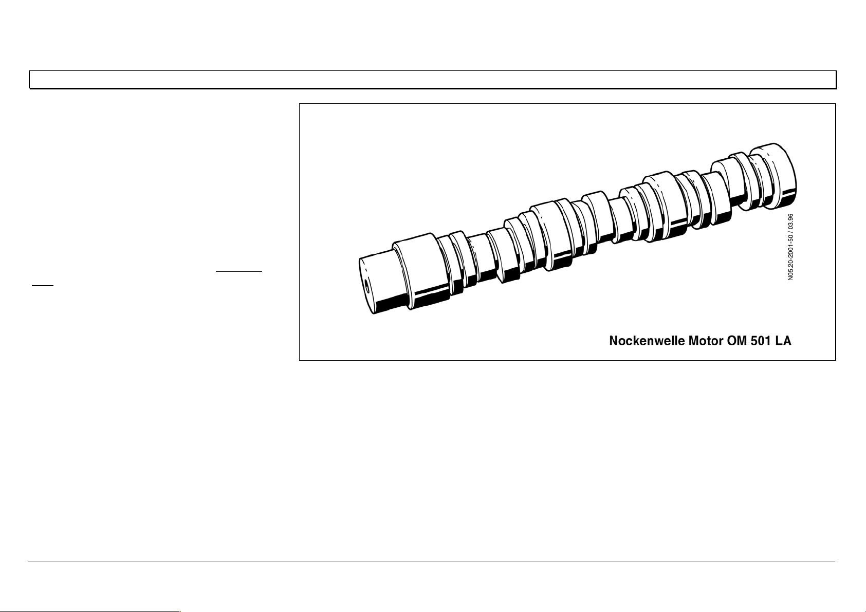
Camshaft
The camshaft is made of high-strength material,
with induction-hardened running surfaces, and
has 4 bearings in the OM 501 LA, 5 bearings in
the OM 502 LA.
Between the bearings are 4 valve timing cams
and 2 injection cams for each opposing cylinder
pair.
The slide ways of the timing cams for the valve
and injection roller tappets are supplied with lube
oil through additional oil holes in the piston jet
pipe.
N05.20-2001-50
05/03 Powersystems • Industrial Engines Maintenance and Repair Series 457, 500 and 900 Advanced Training
Series 500<>Valve assembly
79
Adjusting the valve play
The valve play checking and setting procedure is the same as for the BR 400, and there are two methods.
Method 1
Set the intake and exhaust valves for each cylinder, according to the injection sequence.
The cylinder to be set must be at ignition TDC, the parallel cylinder at valve overlap TDC.
With this method, the crankshaft must be turned six times in the 6-cylinder engine, and eight times in the
8-cylinder engine.
Method 2
Set the intake and exhaust valves in two crankshaft positions.
Adjust when cylinder 1 is at ignition TDC.
Adjust when cylinder 1 is at overlap TDC.
N05.30-0302-01 P
Valve Play
Tolerance
Intake 0.40 + 0.20 / — 0.10
Exhaust 0.60 + 0.20 / — 0.10
The valve play test tolerance applies only for checking valve play.
If valve play is outside the tolerance range, the specified value must be set.
05/03 Powersystems • Industrial Engines Maintenance and Repair Series 457, 500 and 900 Advanced Training
Series 500<>Valve assembly
80
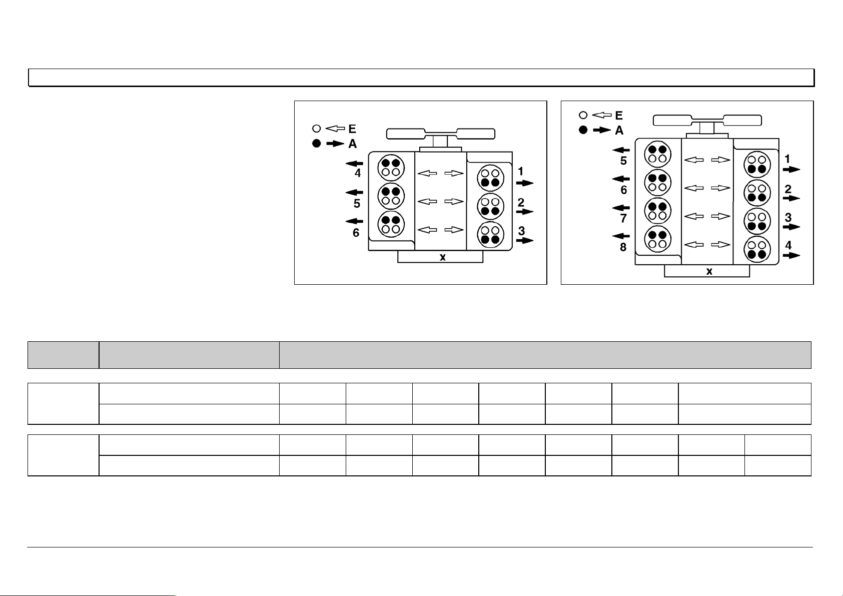
General notes on valve adjustment
Method 1
Set the intake and exhaust valves for each
cylinder, according to the injection sequence.
The cylinder to be set must be at ignition TDC, and
the parallel cylinder at valve overlap TDC.
AExhaust valve
E Intake valve
X Flywheel side
N01.00-0200-01 N01.00-0201-01
Engine Crankshaft position Cylinder/injection sequence
6-cylinder Ignition TDC142536
Valve overlap536142
8-cylinder
Ignition TDC15726348
Valve overlap63481572
05/03 Powersystems • Industrial Engines Maintenance and Repair Series 457, 500 and 900 Advanced Training
Series 500<>Valve assembly
81
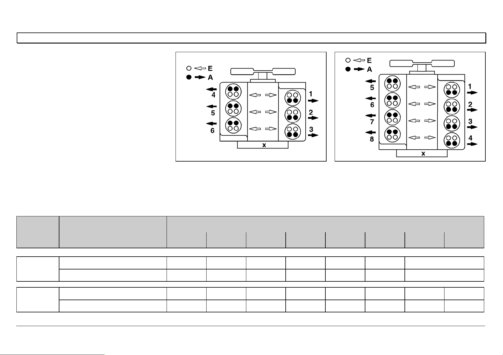
General notes on valve adjustment
Method 2
Set the intake and exhaust valves at two
crankshaft positions, as shown in the table.
AExhaust valve
E Intake valve
X Flywheel side
N01.00-0200-01 N01.00-0201-01
6-cylinder
First set cylinder 5 at valve overlap TDC (cylinder
1 at ignition TDC), then cylinder 1 at valve
overlap TDC (cylinder 5 at ignition TDC).
8-cylinder
First set cylinder 6 at valve overlap TDC (cylinder
1 at ignition TDC), then cylinder 1 at valve
overlap TDC (cylinder 6 at ignition TDC).
Engine Crankshaft position Cylinder/injection sequence
1 2 3 4 5 6 7 8
6-cylinder
Cylinder 5 valve overlap I / E E I E — I
Cylinder 1 valve overlap — I E I I / E E
8-cylinder
Cylinder 6 valve overlap I / E E I I E — E I
Cylinder 1 valve overlap — I E E I I /E I E

05/03 Powersystems • Industrial Engines Maintenance and Repair Series 457, 500 and 900 Advanced Training
Series 500<>Valve assembly
82
05/03 Powersystems • Industrial Engines Maintenance and Repair Series 457, 500 and 900 Advanced Training
Series 500<>Pump-line-nozzle injection system (PLD)
83
Series 500<>Pump-line-nozzle injection system (PLD) 07.05.2003
Engines of the OM 500 model series use the direct
fuel injection process.
The injection process is performed by the newly
developed pump-line-nozzle (PLD) system,
controlled by an electronic engine management
system that has also been newly developed.
In the PLD system, fuel is delivered to the injection
nozzle by individual unit pumps over short, rigid
high-pressure injection lines, and through the
pressure pipe connection screwed into the cylinder
head.
The connection to the nozzle and nozzle holder is
located centrally at the cylinder, and is integrated
with, and removable from, the cylinder head.
A unit pump fitted for each cylinder is located
directly on the crankcase.
N07.02-2018-50

05/03 Powersystems • Industrial Engines Maintenance and Repair Series 457, 500 and 900 Advanced Training
Series 500<>Pump-line-nozzle injection system (PLD)
84
The electronic engine management system controls the injection timing point and quantity injected individually per cylinder, by means of solenoid valves.
Separation of the high pressure pump and injection nozzle made it necessary to develop a high pressure injection line of special tube material with a surface
hardened by internal high pressure forming, able to support continuous injection pressures over 2000 bar.
With high pressure injection (peak pressures up to 1800 bar) together with the central, vertically positioned nozzle with 8 or 6 injection orifices and flat
combustion chamber cavity in the piston, outstanding particulate values are achieved.
Advantages over the Pump-Nozzle system
¦ No overhead camshaft
— therefore lower space requirement and reduced engine height
— lower noise emission
¦ On the V-engine, only one camshaft needed, which controls both cylinder banks.
— Weight saving
¦ Locating the camshaft in the center of the crankcase means there is optimal power absorption. With an overhead camshaft, measures would be
necessary for strengthening the cylinder head.
¦ Easy to repair
— Individual cylinder heads, which are all identical
— Compact unit pumps, which are simple to replace
— Inexpensive replacement due to separate pump and nozzle
05/03 Powersystems • Industrial Engines Maintenance and Repair Series 457, 500 and 900 Advanced Training
Series 500<>Pump-line-nozzle injection system (PLD)
85
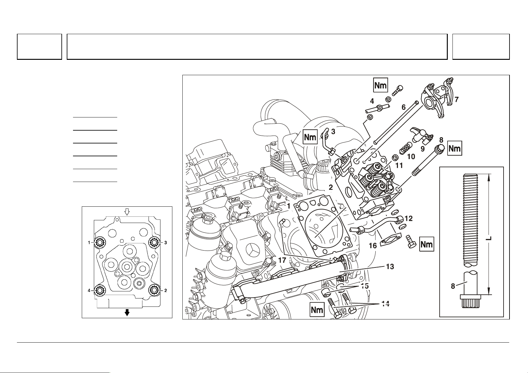
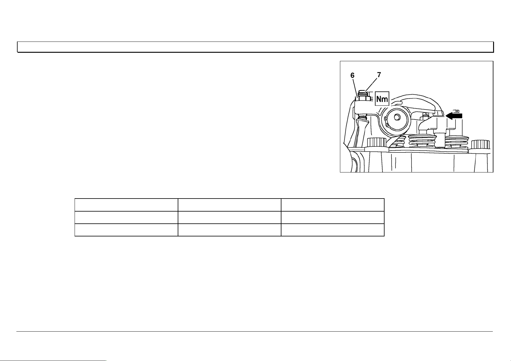
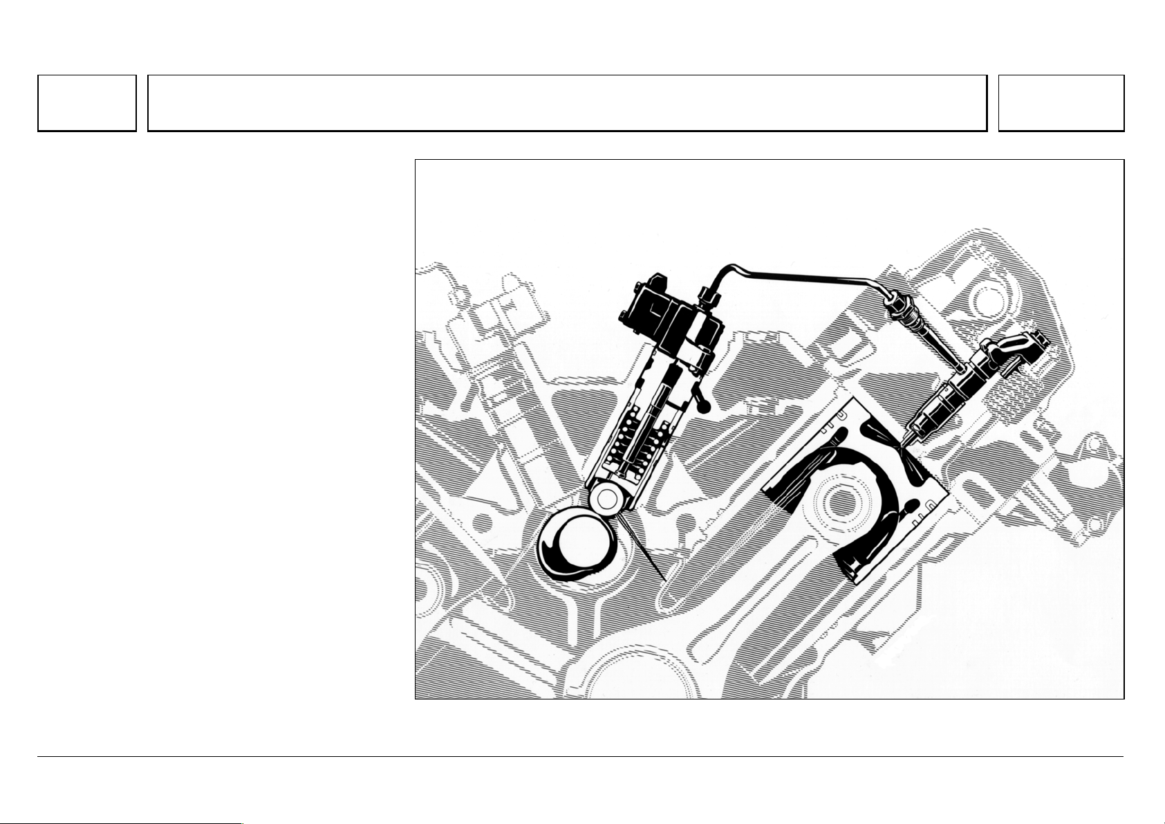
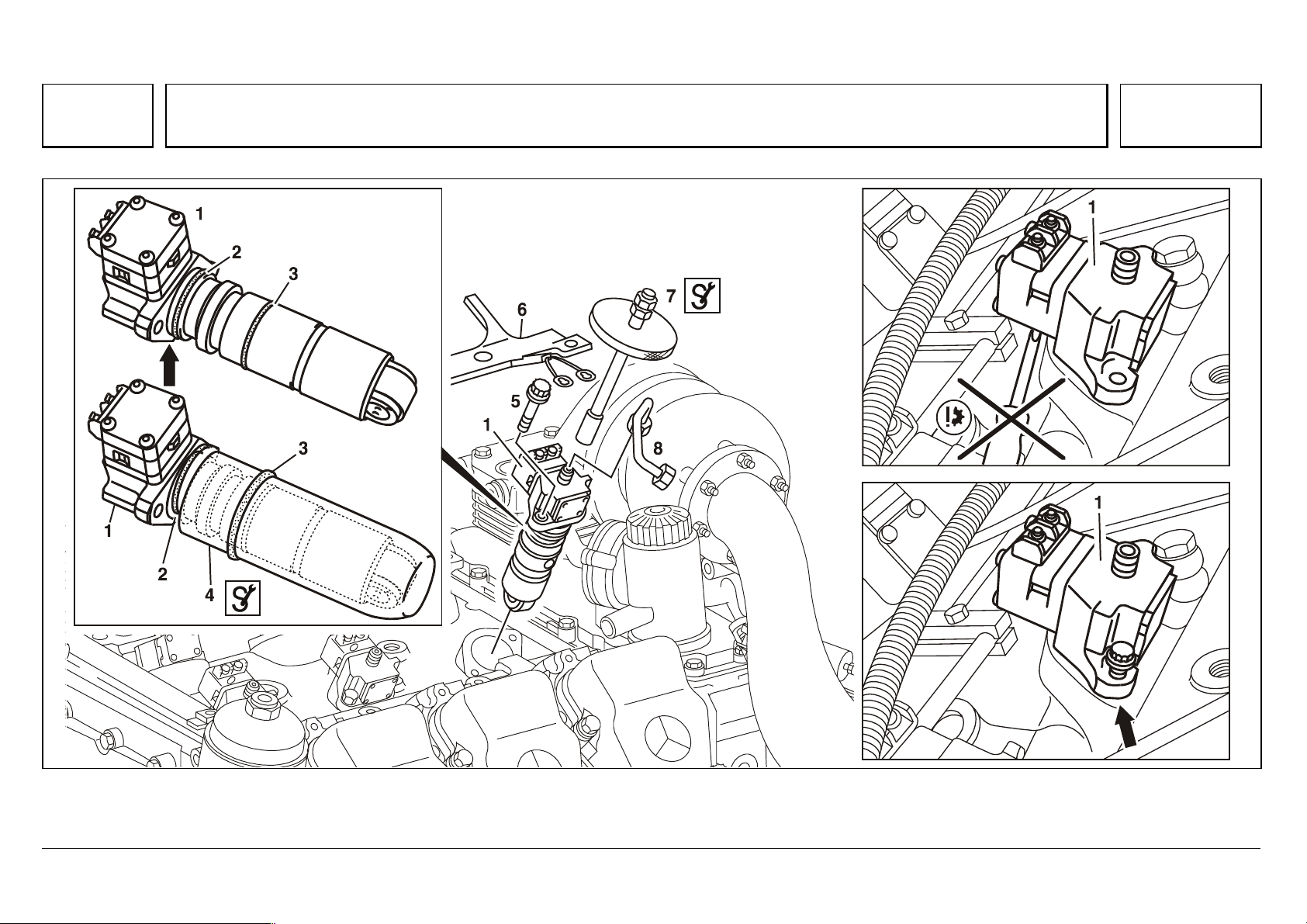
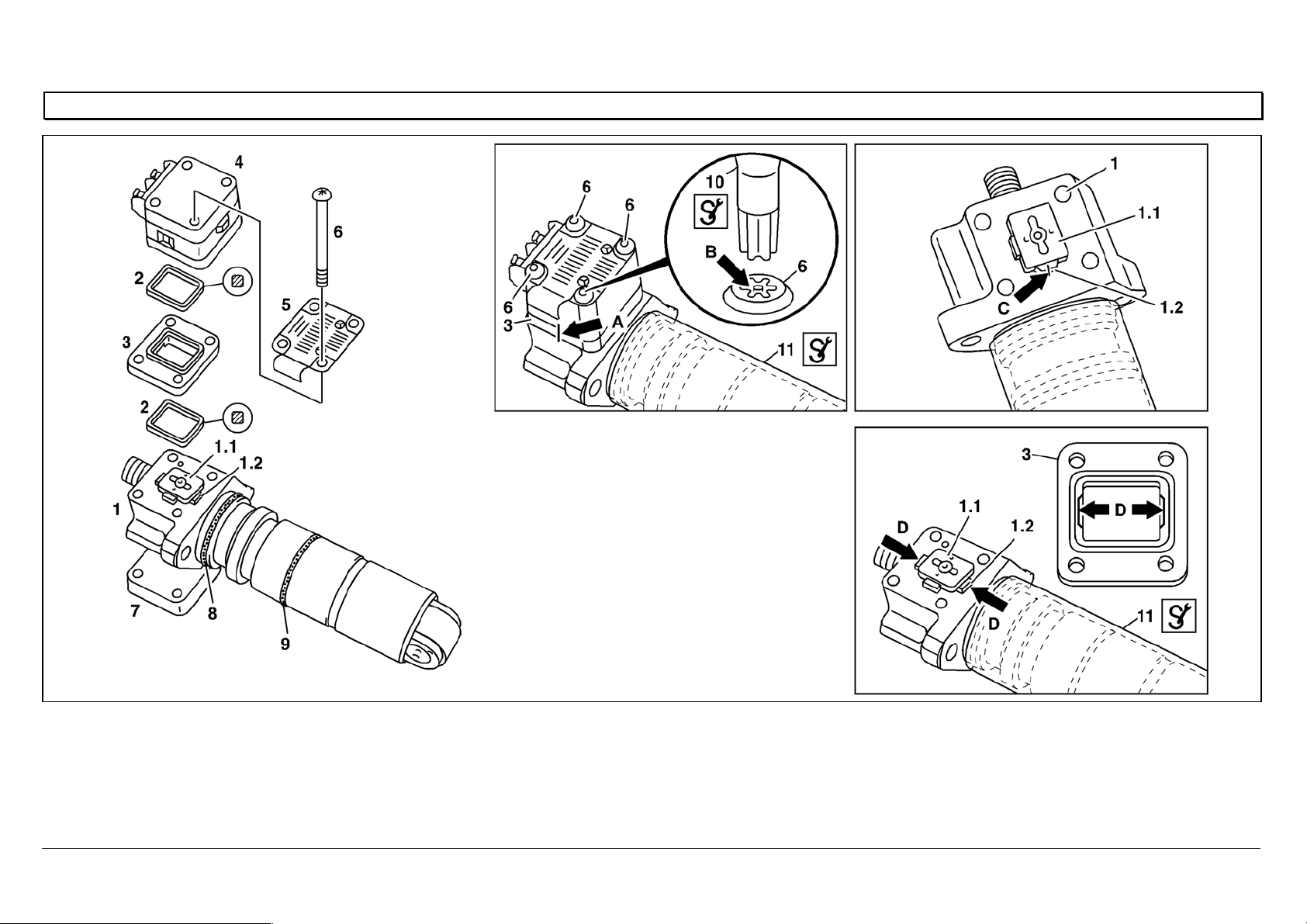
Pressure pipe connection and nozzle holder location
Connection to the nozzle holder and injection
nozzle (positioned vertically at the center of the
cylinder), is through a fixed, preassembled
pressure pipe connection with integral pin-type
filter.
The nozzle holder with 8 or 6-hole injection nozzle
is held in a protective sleeve by means of a
clamping claw supported on the nozzle holder and
constant throttle cap, and attached with a central
screw.
The seal at the nozzle protective sleeve consists
of a copper spacer or sealing sleeve.
For nozzle holder positioning, the clamping claw
grips a locating pin fixed into the nozzle holder
cap.
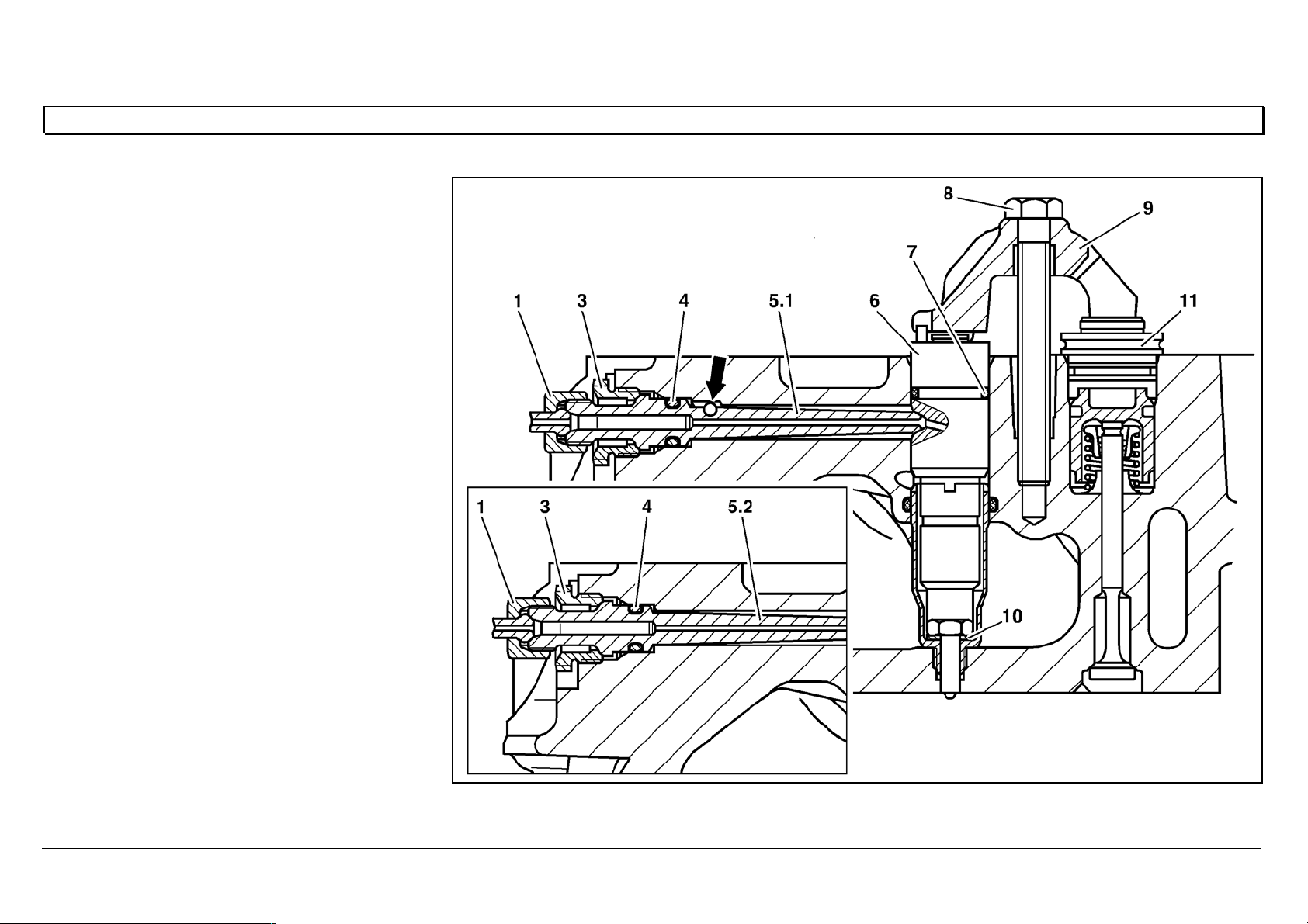
The pressure pipe connection is attached with a
press-in ball fastening.
1 Injection line, 30 [Nm]
3 Pressure screw, 40 [Nm]
4O—ring
5.1 Pressure pipe connection with anti-twist lock
(press-in ball fastening)
5.2 Pressure pipe connection without anti-twist lock
6 Nozzle holder combination
7O—ring
8 Screw, 50 Nm,
£ 91 mm
9Retaining clip
10 Sealing ring
11 Constant throttle cap
W07.03-1006-06
05/03 Powersystems • Industrial Engines Maintenance and Repair Series 457, 500 and 900 Advanced Training
Series 500<>Pump-line-nozzle injection system (PLD)
86
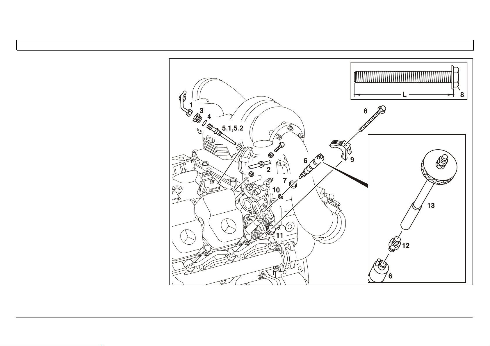
Removing/installing the nozzle holder combination
1 Injection line, 30 Nm
2 Leak fuel line, 15 Nm
3 Pressure screw, 40 Nm
4O—ring
5.1 Pressure pipe connection with anti-twist
lock (press-in ball)
5.2 Pressure pipe connection without anti-
twist lock
6 Nozzle holder combination
7O—ring
8 Screw, 50 Nm
9 Retaining clip
10 Sealing ring or sealing sleeve
11 Constant throttle cap
12 Adapter 904 589 00 63 00
13 Extractor 355 589 01 63 00
L Shank length of screw (8), £ 91 mm
W07.03-1005-06

05/03 Powersystems • Industrial Engines Maintenance and Repair Series 457, 500 and 900 Advanced Training
Series 500<>Pump-line-nozzle injection system (PLD)
87
To remove
1.
Risk of explosion due to gas ignition, risk of poisoning by inhaling or
absorbing fuel, or risk of injury to skin and eyes through contact with fuel.
Fire, sparks, naked flames, smoking are forbidden. Only store fuel in
suitable and appropriately marked containers. Wear protective clothing if
handling fuel.
2.
Remove the cylinder head cover
3.
Remove leak fuel line (2) from cylinder head
4.
Remove injection line (1)
5.
Unscrew pressure screw (3) and remove pressure pipe connection (5).
6.
Remove retaining clip (9)
7.
Fit the adapter (12) and extractor (13) to the inside thread (M  of nozzle
holder combination (6)
Adapter: 904 589 00 63 00
Extractor: 355 589 01 63 00
8.
Take out the nozzle holder combination (6) The nozzle holder combination should not be disassembled. If worn or
faulty, the nozzle holder combination must be replaced.
9.
Remove the adapter (12) and extractor (13) from nozzle holder
combination (6)
10.
Take out the sealing ring (10)
To install
1.
Measure the shank length of screw (8).
i If the maximum shank length is exceeded, replace the screw.
MB Standard 10105 screws are generally to be replaced by screws with
an MB Part No. on the screw head.
2.
Insert a new O-ring (7) at nozzle holder combination (6)
i Grease the O-ring.
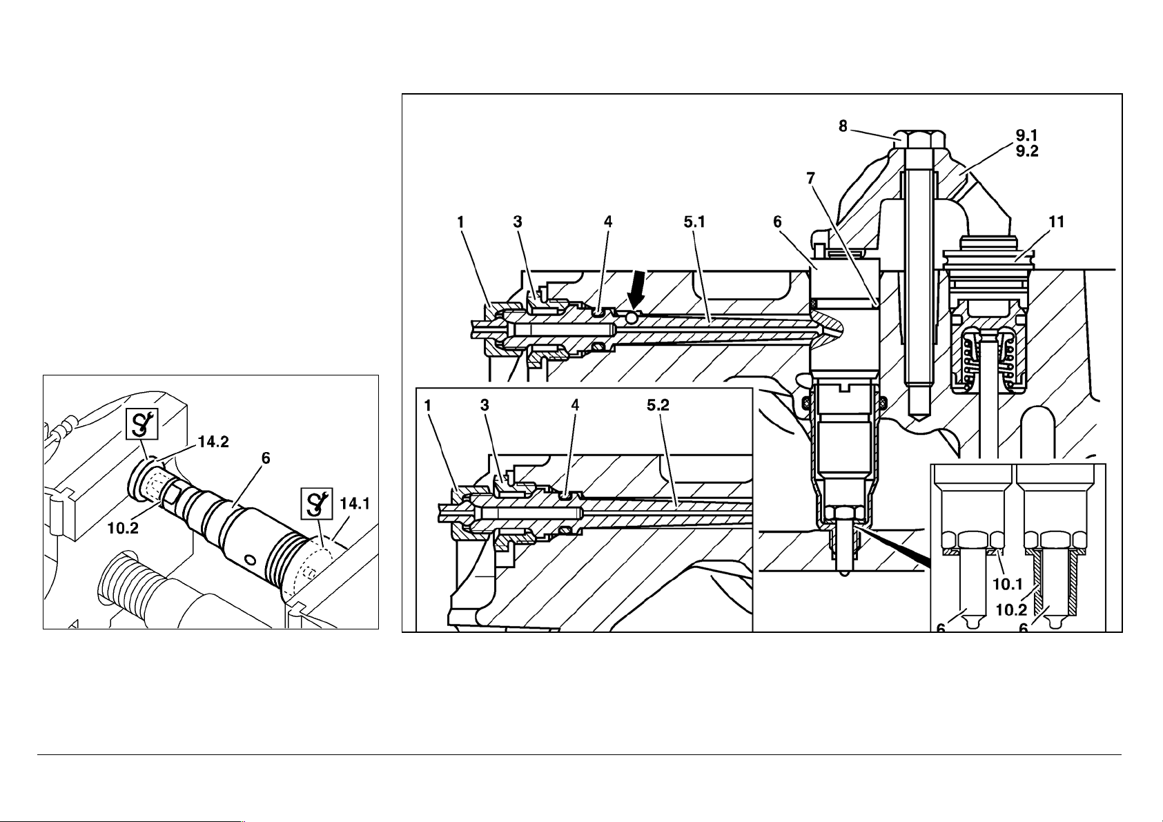
3.1
Place the new O-ring (10.1) at nozzle holder combination (6)
i Up to engine End Number 197928
Note the installation location and thickness of the sealing ring: the smaller
ring surface should point towards the nozzle holder combination.
Grease the sealing ring.

05/03 Powersystems • Industrial Engines Maintenance and Repair Series 457, 500 and 900 Advanced Training
Series 500<>Pump-line-nozzle injection system (PLD)
88
3.2
Press new sealing sleeve (10.2) onto nozzle holder combination (6)
i From engine End Number 197928
Before pressing on the new sealing sleeve, the contact surface of the
sealing sleeve should be cleaned to remove combustion residues (using a
wire brush or ultrasonic equipment, for example).
#Clean the nozzle holder combination.
i Grease the sealing sleeve.
l
4.
Install nozzle holder combination (6)
iNote installation location of nozzle holder combination at the pressure
pipe connection hole. Twist the nozzle holder combination with retaining
clip (9) into the cylinder head until the retaining clip (9.1 or 9.2) clips onto
the locating pin on the cap of constant throttle (11).
5.
Mount the retaining clip (9.1 or 9.2), 50 Nm
n
6.
Place the new O-ring (4) at pressure pipe connection (5).
i Grease the O-ring.
7.
Fit the pressure pipe connection (5.1 or 5.2) and tighten pressure screw
(3),40 Nm
i Pressure pipe connections with anti-twist lock (5.1, press-in ball)
should not be fitted to cylinder heads without a groove (arrowed). The ball
(arrowed) must be inserted in the groove (arrowed).
Damaged pressure pipe connections with an anti-twist lock can be
replaced by the modified pressure pipe connection without anti-twist lock
(5.2).
i Moisten the pressure pipe connection around the taper seal with
engine oil.
n
8.
Install the injection line (1)
9.
Fit the leak fuel line (2), 15 Nm
n
10.
Fit the cylinder head cover
05/03 Powersystems • Industrial Engines Maintenance and Repair Series 457, 500 and 900 Advanced Training
Series 500<>Pump-line-nozzle injection system (PLD)
89
W07.03-1020-01 W07.03-1019-06
05/03 Powersystems • Industrial Engines Maintenance and Repair Series 457, 500 and 900 Advanced Training
Series 500<>Pump-line-nozzle injection system (PLD)
90
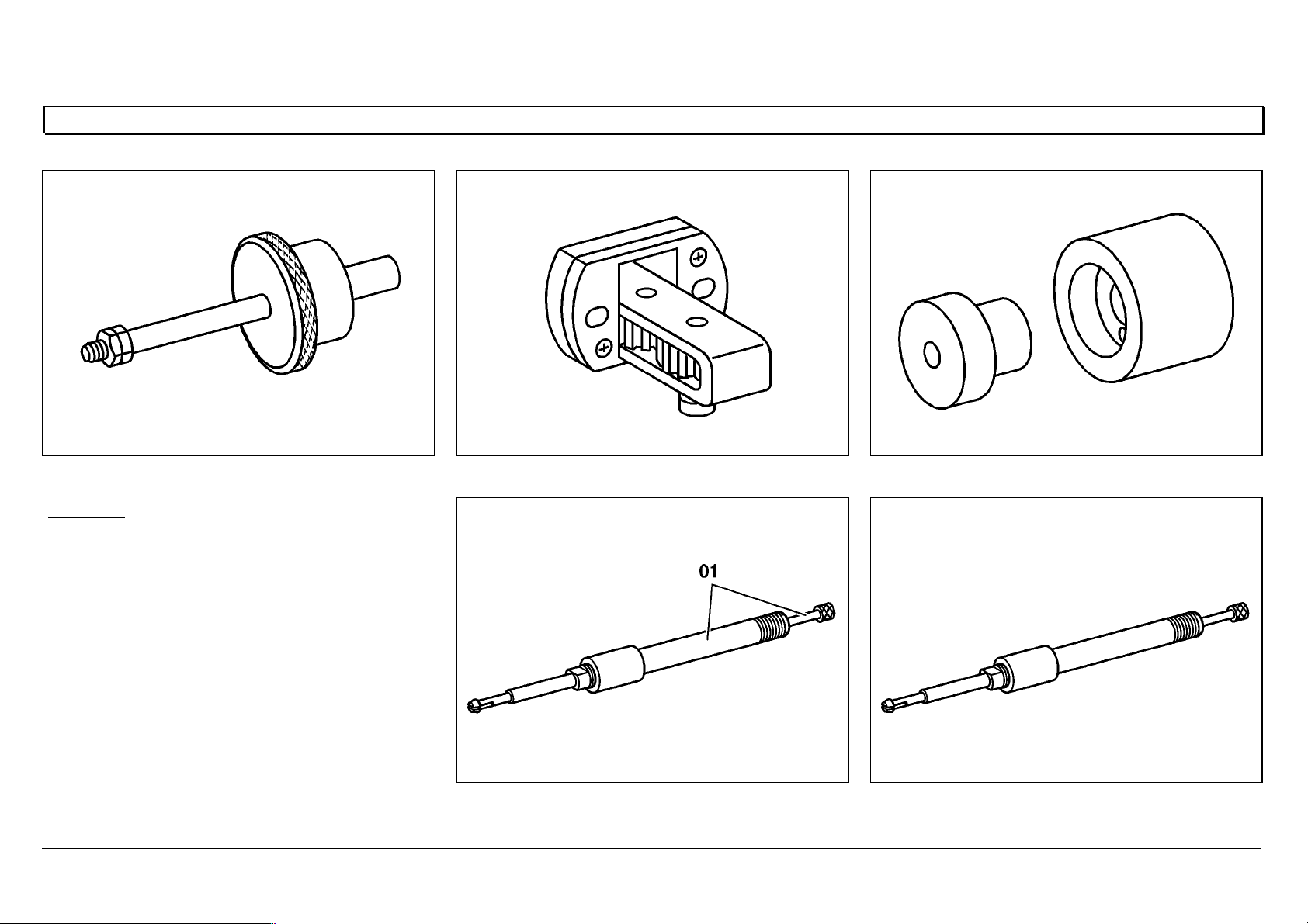
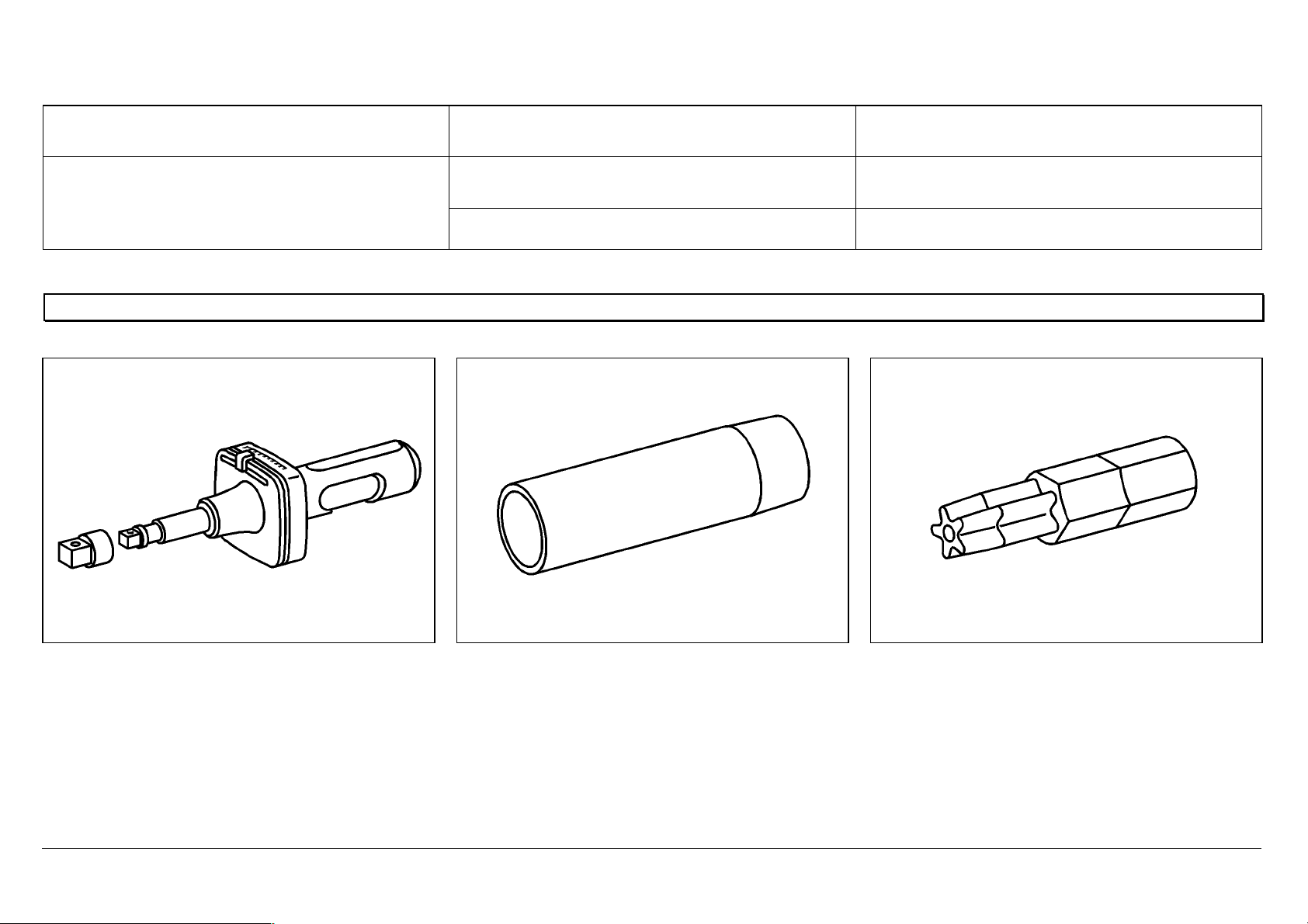
Special tools
355_589_01_63_00 904_589_00_63_00 906_589_00_63_00
Remarks:
3.) Extracting tool 906 589 02 63 00 is now
usually supplied together with the extension.
4.) From April 2003, for new orders under the
existing number, special tool 906 589 00 63
00 is supplied with modification to Part 1. To
extend existing tools, the modified Part 1
can also be ordered separately under
number 906 589 00 63 01.
906_589_02_63_00
Extracting tool extension
906_589_02_63_01
1
05/03 Powersystems • Industrial Engines Maintenance and Repair Series 457, 500 and 900 Advanced Training
Series 500<>Removing/installing the MR/PLD unit pump
91
Series 500<>Removing/installing the MR/PLD unit pump 07.05.2003
W07.15-1057-09
1MR/PLD unit pump
2 O-ring (black)
3 O-ring (brown)
4 Protective sleeve 541 589 01 14 00
5 Splined bolt, 65 Nm
6 Cable duct with engine wiring harness
7 Extractor 355 589 01 63 00
8 Injection line, M16×1.5, 50Nm

05/03 Powersystems • Industrial Engines Maintenance and Repair Series 457, 500 and 900 Advanced Training
Series 500<>Removing/installing the MR/PLD unit pump
92
Removing/installing
1. Risk of explosion due to gas ignition, risk of poisoning by inhaling or
absorbing fuel, or risk of injury to skin and eyes through contact with fuel.
Fire, sparks, naked flames, smoking are forbidden. Only store fuel in
suitable and appropriately marked containers. Wear protective clothing if
handling fuel.
2. Remove the charge air pipe
3. Remove injection line (8) Stop up the orifices in the nozzle holder combination and MR/PLD unit
pump (1).
4. Clean the crankcase around the MR/PLD unit pumps (1). Cover the intake orifices in the cylinder heads.
5.
Remove engine wiring harness (6) at all MR/PLD unit pumps (1) on left or
right.
To do this, loosen the screws on the solenoid valve and detach both clip
fasteners.
6. Identify the MR/PLD unit pump (1) for the cylinder concerned Only if removing more than one or all MR/PLD unit pumps
7. Loosen the splined bolts (5) For reasons of safety, the splined bolts should be unscrewed by only
about 4 to 5 mm; the MR/PLD unit pump is under spring load.
Installation: Press the MR/PLD unit pump into the crankcase with the
splined bolts, tightening slowly and alternating between bolts. Tighten the
splined bolts to 65 Nm
8. Fit the extractor (7) to MR/PLD unit pump (1) Extractor: 355 589 01 63 00

05/03 Powersystems • Industrial Engines Maintenance and Repair Series 457, 500 and 900 Advanced Training
Series 500<>Removing/installing the MR/PLD unit pump
93
9. Pull out the MR/PLD unit pump (1) with the extractor (355 589 01 63 00)
up to the bolt heads
Remove the fuel lines or fuel overflow valve on the crankcase if necessary.
Banjo bolt of fuel line to port in crankcase, 50Nm.
Banjo bolt of fuel line to fuel overflow valve, 50 Nm.
If stuck, the MR/PLD unit pump should not be pressed out at the solenoid
valve and housing flange.
Carefully press out the MR/PLD unit pump at the cutout (arrowed) in the
unit pump housing.
Installation: Lightly oil the unit pump body, O-ring surfaces (2, 3), and
hole in the crankcase with engine oil. Do not tilt the MR/PLD unit pump
when inserting in the crankcase. Carefully press in the MR/PLD unit pump
by hand, to a depth of about 4 mm.
If the unit pump cam on the camshaft is at the top, turn the engine by a
half-revolution (in direction of rotation).
10. Unscrew the splined bolts (5) and pull out the MR/PLD unit pump (1) Installation: Carefully remove dirt and paint residues from the sealing
surface (arrowed) of the MR/PLD unit pump and crankcase.
11. Check the MR/PLD unit pump
Check the roller on roller tappet; if there is only slight scoring or
scratching, the MR/PLD unit pump can be used again. If there is deep
scoring, scratching, or sanding spots:
Install a new MR/PLD unit pump
12. Remove O-rings (2, 3) from the MR/PLD unit pump (1) Installation: Clean the radial groove in the unit pump body.
Push protective sleeve (541 589 01 14 00) over the unit pump body, coat
the new O-rings with engine oil; slip the black O-ring, (2) over the
protective sleeve into the top groove, then the brown O-ring (3) into the
lower groove. Avoid twisting the O-rings when fitting into the grooves.
13. Install in the reverse order

05/03 Powersystems • Industrial Engines Maintenance and Repair Series 457, 500 and 900 Advanced Training
Series 500<>Removing/installing the MR/PLD unit pump
94
Unit pump classification
The BR 457, 500 and 900 unit pumps are classified at manufacture.
When each pump is installed in the engine on the assembly line at Mannheim,
its classification is registered and stored in the MR electronic system.
To ensure smooth engine running, the classification values are taken into
account when distributing the fuel quantity (injection timing).
To ensure that smooth engine running continues after unit pumps are replaced
or modified for diagnostic purposes, the unit pump classification must be
assigned to the cylinder.
An input error may lead to rough engine running and overloading of
individual cylinders.
Then reset the individual cylinder torque control to «0».
AXOR MR
Replace unit pump
Cylinder Code
1 Cylinder 1 X-XXX-XXX-XX-XXXXX
2 Cylinder 2 X-XXX-XXX-XX-XXXXX
3 Cylinder 3 X-XXX-XXX-XX-XXXXX
4 Cylinder 4 X-XXX-XXX-XX-XXXXX
5 Cylinder 5 X-XXX-XXX-XX-XXXXX
6 Cylinder 6 X-XXX-XXX-XX-XXXXX
Note:
The user must read off the unit pump number on the
unit pump, and enter it for the corresponding
cylinder. Only enter the unit pump number
for pumps being replaced.
To confirm, press F3.
05/03 Powersystems • Industrial Engines Maintenance and Repair Series 457, 500 and 900 Advanced Training
Series 500<>Removing/installing the MR/PLD unit pump
95
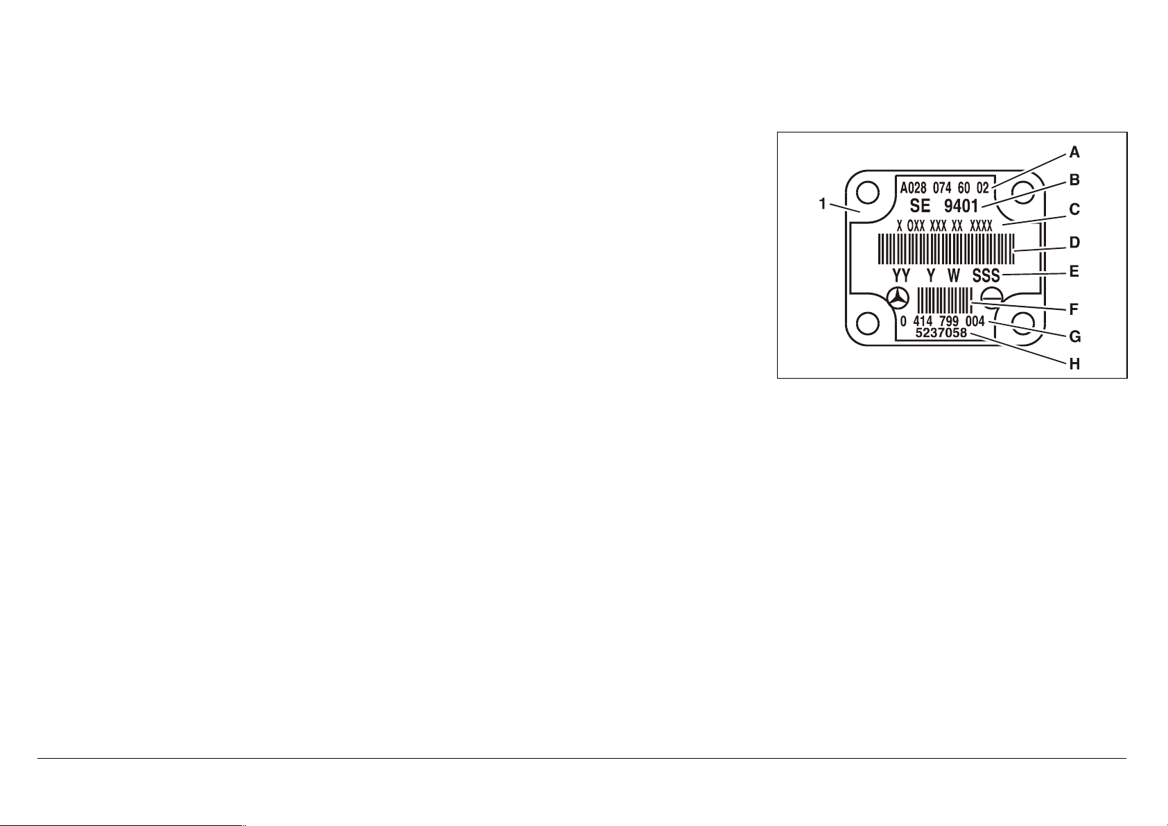
The classification is coded as a 14-digit number (C) on the unit pump model plate. The code is entered
through the «Replace Unit Pump» menu in DAS.
A = MB number
B = Certification number
C = Unit pump number (classification)
D = Bar code
E, G, H = Manufacturer information
F = Manufacturer bar code
N07.02-2028-01
05/03 Powersystems • Industrial Engines Maintenance and Repair Series 457, 500 and 900 Advanced Training
Series 500<>Removing/installing the MR/PLD unit pump
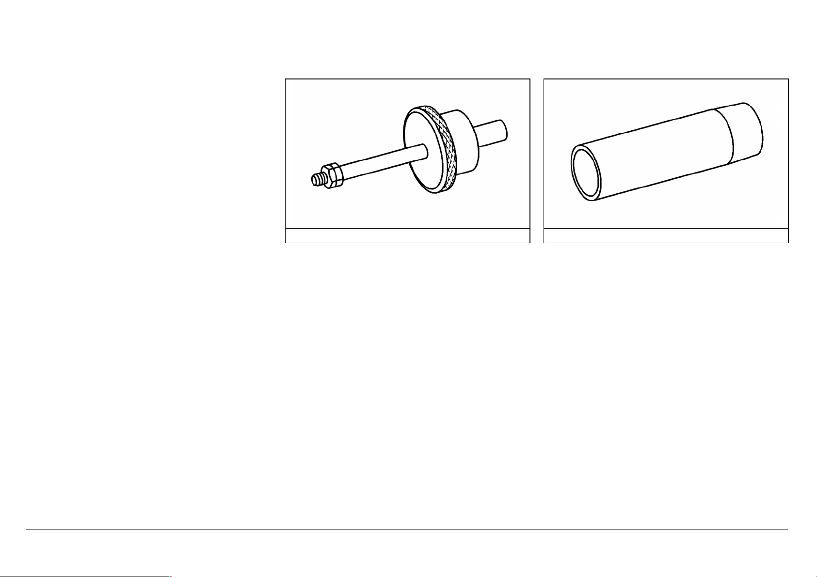
96
355 589 01 63 00 541 589 01 14 00
05/03 Powersystems • Industrial Engines Maintenance and Repair Series 457, 500 and 900 Advanced Training
Series 500<>Removing/installing the MR/PLD unit pump
97
Sealing the intermediate plate of the unit pump
W07.15-1058-09
1 Pump body 2 Seal 5 Model plate 8 O-ring 10
lScrewdriver bit
1.1 Anchor plate 3 Intermediate plate 6 Screw 9 O-ring 11
lSleeve
1.2 Crosspiece 4 Solenoid 7 Stop plate

05/03 Powersystems • Industrial Engines Maintenance and Repair Series 457, 500 and 900 Advanced Training
Series 500<>Removing/installing the MR/PLD unit pump
98
e
To remove
p
Utmost cleanliness should be ensured whenever working on the unit pumps.
1 Remove the MR/PLD unit pump
2 Remove O-rings (8,9,) from the unit pump (1)
p First clean the bottom part of the pump body
(1).
3 Push the sleeve (11) onto unit pump (1)
p So that dirt will not get into the orifices.
l
4 Clean the upper part of the MR/PLD unit pump.
p Carefully remove paint residues on the sealing
surfaces of the MR/PLD unit pump.
i The high pressure orifice must be closed off.
No dirt or cleaning agent should be allowed to
penetrate into the pump body (1).
5 Identify the intermediate plate (3) (arrow A) for the pump body (1) and place the MR/PLD
unit pump at the stop plate.
p Use a scriber or touch-up pencil, never a
stamping tool.
6 Loosen the screws (6), and remove solenoid (4) together with intermediate plate (3) and
model plate.
i First remove paint residues from the screw
heads with a scriber (arrow B).
l
7 Remove intermediate plate (3) and model plate (5) from solenoid (4).
i Clean the sealing surface of the solenoid.
8 Take out sealing rings (2) and clean intermediate plate (3)
p Do not damage the sealing surfaces.
9 Identify the crosspiece (1.2) and anchor plate (1.1) for pump body (1) (arrow C).
p Use a touch-up pencil, never a scriber or
stamping tool.
The crosspiece should not be moved or turned.
10 Apply cleaning spray to the sealing surfaces of pump body (1), crosspiece (1.2) and anchor
plate (1.1).
p Clean the parts carefully.
i Do not remove paint residues from the pump
body (1), these will be needed for locating the
intermediate plate (3).

05/03 Powersystems • Industrial Engines Maintenance and Repair Series 457, 500 and 900 Advanced Training
Series 500<>Removing/installing the MR/PLD unit pump
99
11 Take off stop plate (7)
p Remove paint residues around the contact
surface of the screw heads.
Do not remove the protective foil on the model
plate.
12 Clean the model plate (5)
d
To install
13 Place new stop plate (7) under the pump body (1).
14 Insert new seals (2) in the intermediate plate (3).
i Protect the seals with grease
15 Place intermediate plate (3) on pump body (1).
p Pay attention to the identification marks on the
crosspiece (1.2) and anchor plate (1.1) for pump
body (1). The cutouts (arrows D) at the opening in
the intermediate plate must point towards the
crosspiece (1,2).
i The paint residues are used to locate
intermediate plate (3) on pump body (1).
16 Insert the solenoid (4) on intermediate plate (3).
17 Assemble the model plate (5), solenoid(4), intermediate plate (3), pump body (1) and stop
plate (7) and fasten with new screws (6).
ni Tighten the screws crosswise.
l904 589 02 10 00
l001 589 80 21 00
18 Take off sleeve (11)
l541 589 01 14 00
19 Install MR/PLD unit pumps
i Fit new O-rings (8,9), following the installation
specification.
05/03 Powersystems • Industrial Engines Maintenance and Repair Series 457, 500 and 900 Advanced Training
Series 500<>Removing/installing the MR/PLD unit pump
100
n MR/PLD unit pump
Engine 541.9, 542.9
Screw, solenoid valve to MR/PLD unit pump Step 1 [Nm] 2
Step 2 [Nm] 4
Special tools
Torque screwdriver 001_589_80_21_00 Sleeve 541_589_01_14_00 Screwdriver bit 904_589_02_10_00
05/03 Powersystems • Industrial Engines Maintenance and Repair Series 457, 500 and 900 Advanced Training
Series 500<>EURO 2 and EURO 3 pistons
101
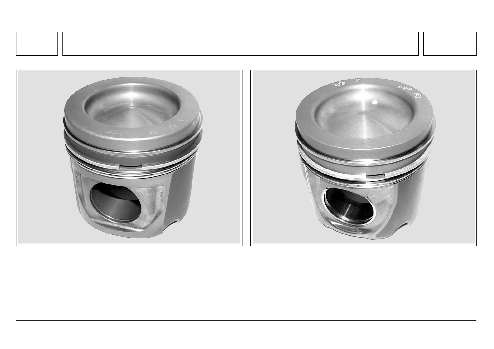
Series 500<>EURO 2 and EURO 3 pistons 07.05.2003
Euro 2 piston
N03.10-2051-11
Euro 3 piston
N03.10-2052-11
From 02/00, quality improved by reduced ring wear and oil consumption and
optimized bore profile for longer service life.
From 03/00 for Euro 3 engines: Modified combustion chamber, use of hub
liner to prevent strain cracks and improve cylinder properties. The radial
grooves and piston rings have also been modified to further reduce oil
consumption.
05/03 Powersystems • Industrial Engines Maintenance and Repair Series 457, 500 and 900 Advanced Training
Series 500<>Connecting rod
102
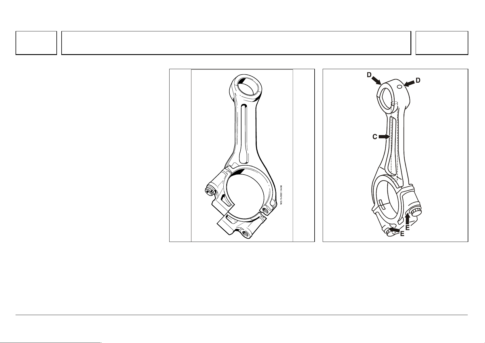
Series 500<>Connecting rod 07.05.2003
The steel connecting rod is partially forged. The
separation of connecting rod from bearing cap is
made by ‘cracking’.
Compared with the conventional, costly separating
process, ‘cracking’ brings high dimensional
stability to the large connecting rod eye.
The separation point at the large connecting rod
eye is set obliquely.
Connecting rod and bearing cap are linked
positively and frictionally with each other by two
stretch-thread bolts.
The ignition power is absorbed evenly at the small,
trapezoidal connecting rod eye by a solid bronze
bushing, which is supplied with sufficient lube oil
from the large connecting rod eye through a
pressure oil hole.
N03.10-2002-03 N03.10-2021-02
Due to the intermediate flange needed on the crankshaft in the V6 engines, the width of the connecting
rod at the connecting rod eye is fixed at 34 mm. In the V8 engines, the width is 37 mm.
From about 06/98, there has been a modification
to the oil feed at the small end bearing. Two oil
holes (D) have been made in the connecting rod
eye for the oil supply to the small end bearing.
The long oil hole (C) for the pressure oil supply to
the small end bearing has been removed.
05/03 Powersystems • Industrial Engines Maintenance and Repair Series 457, 500 and 900 Advanced Training
Series 500<>Crankcase
103
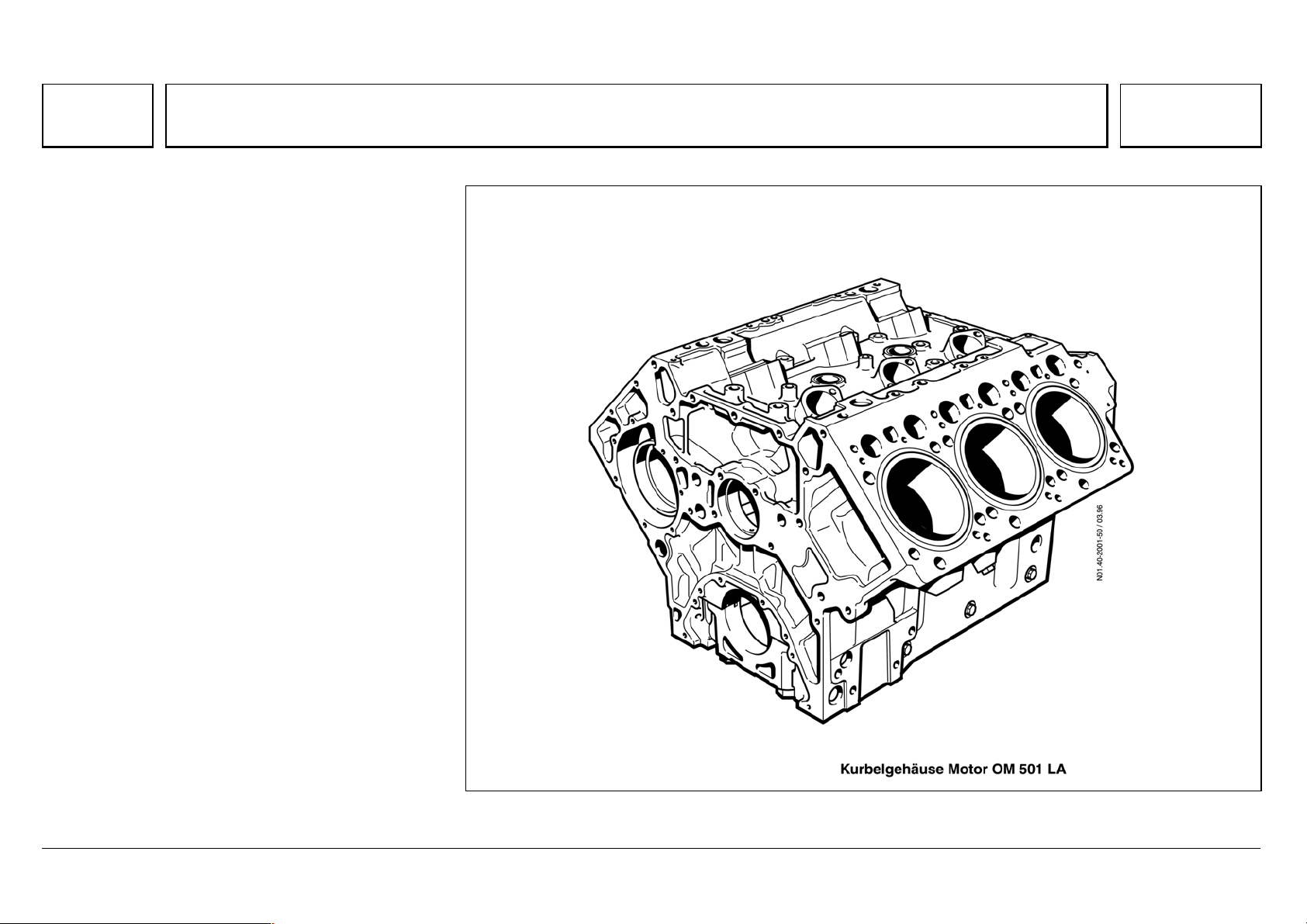
Series 500<>Crankcase 07.05.2003
Design features:
* Compact design, by integrating the oil cooler,
coolant pump coil, unit pumps, and the coolant,
fuel and oil ducts.
* Highly rigid alloy cast iron.
* Rigid crankcase deck and stable liner bottom
collar support, with low-set threads on the
cylinder head bolts. This results in low-warp
absorption of the thread connection and ignition
forces by the rigid collar of the wet cylinder liner.
* Rigid side walls extending well below the center
of the crankshaft, and bolted together with the
crankshaft bearing caps.
N01.40-2001-50
05/03 Powersystems • Industrial Engines Maintenance and Repair Series 457, 500 and 900 Advanced Training
Series 500<>Cylinder liners
104
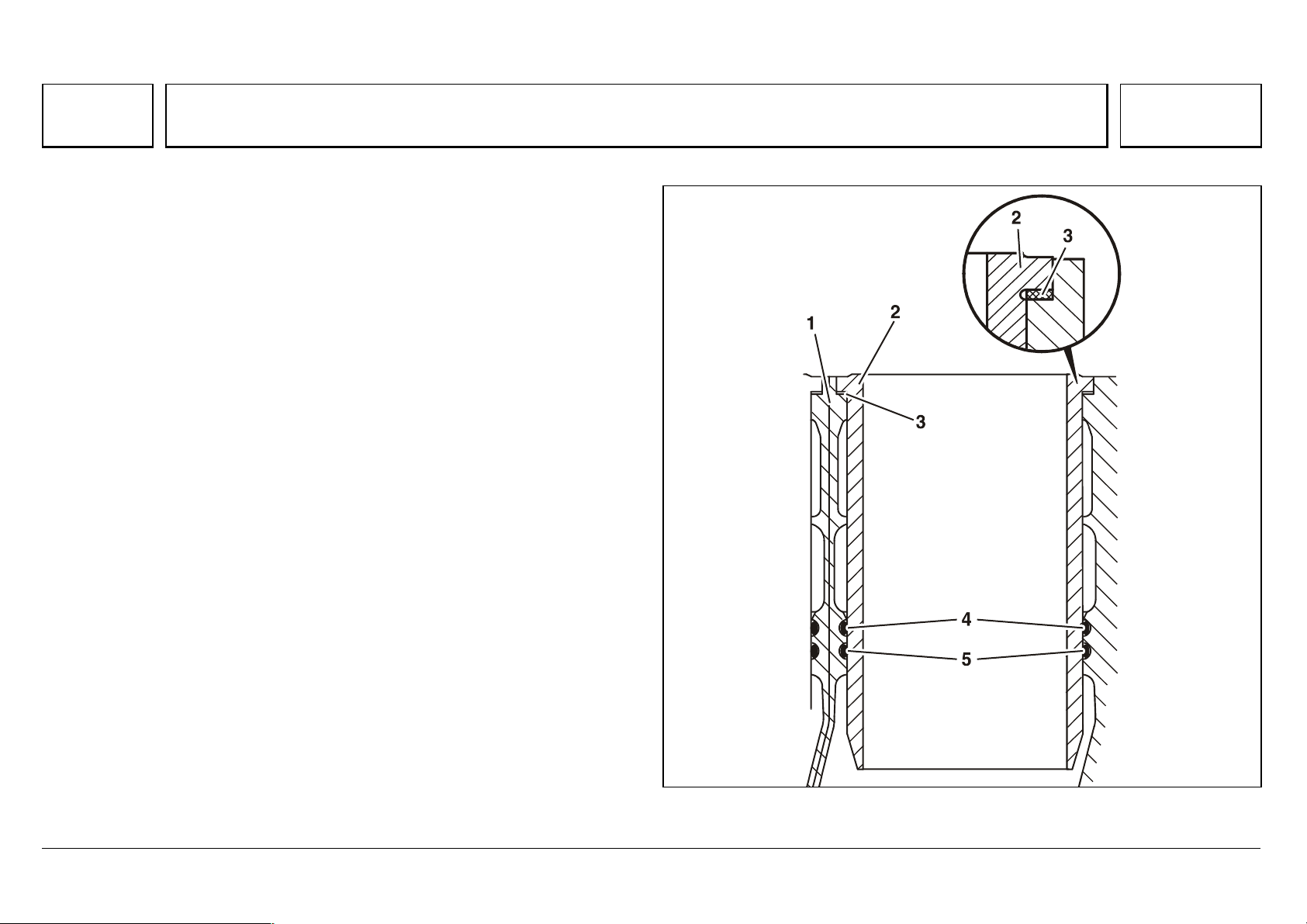
Series 500<>Cylinder liners 07.05.2003
A tombac ring (0.15 mm) is placed under the upper cylinder liner collar
support where the thermal load is high, and forms the seal on the water side.
The lower end is sealed by two high-temperature, oval Viton rings, on both the
water and oil side.
1Crankcase
2 Cylinder liner
3Tombac ring
4,5 Oval Viton ring
N01.40-2019-03
 Loading…
Руководство по эксплуатации OM 457 LA, OM 460 LA Mercedes-Benz (КамАЗ).
Перед вводом двигателя в эксплуатацию ознакомьтесь с Вашим двигателем и прочтите “Руководство по эксплуатации”. Это позволит Вам избежать опасные для себя и других ситуации.
Комплектация или наименование изделия Вашего двигателя различаются в зависимости от индивидуально определенного объема поставки. Эти данные находятся в паспортной карточке двигателя.
OM 457 LA, OM 460 LA.
Скачать.
Поделиться ссылкой:
Похожие статьи
2,99 Мб
-
Год:
2014
-
Страниц:
104
-
Формат:
pdf
-
Язык:
английский
-
Размер:
2,99 Мб
Руководство по эксплуатации двигателей Mercedes-Benz OM457LA и OM460LA Скачать Бесплатно
Скачать2,99 Мб
Категории: Руководства, Двигатели, Двигатели Daimler-Benz, Двигатели Mercedes-Benz, Двигатель Mercedes-Benz OM457, Двигатель Mercedes-Benz OM457LA, Двигатель Mercedes-Benz OM457LA BlueTec, Двигатель Daimler-Benz OM457, Двигатель Daimler-Benz OM457LA, Двигатель Daimler-Benz OM457LA BlueTec, Двигатель Mercedes-Benz OM460, Двигатель Mercedes-Benz OM460LA, Двигатель Mercedes-Benz OM460LA BlueTec, Двигатель Daimler-Benz OM460, Двигатель Daimler-Benz OM460LA, Двигатель Daimler-Benz OM460LA BlueTec
ПОКАЗАТЬ ВСЕСВЕРНУТЬ

- Главная
- Книги
- Двигатели Detroit Diesel МВЕ 4000 (Mercedes-Benz OM 460 LA). Руководство по обслуживанию и ремонту
- Добавить цитату
- Добавить тест
- Сейчас читаю
- Добавить в подборку
- Читать позднее
- Написать рецензию
- Поделиться в соцсетях
- Правообладателям
- Сообщить об ошибке

Описание книги
В настоящем издании представлено руководство по обслуживанию и ремонту двигателей Detroit Diesel MBE 4000 (Mercedes-Benz ОМ 460 LA).
Книга будет полезна всем владельцам техники, оснащенной такими двигателями, специалистам, работающим в области ремонта двигателей, а также всем интересующимся двигателями подобного класса. Книга «Двигатели Detroit Diesel МВЕ 4000 (Mercedes-Benz OM 460 LA). Руководство по обслуживанию и ремонту» автора М. Сизов оценена посетителями КнигоГид, и её читательский ре…
В настоящем издании представлено руководство по обслуживанию и ремонту двигателей Detroit Diesel MBE 4000 (Mercedes-Benz ОМ 460 LA).
Книга будет полезна всем владельцам техники, оснащенной такими двигателями, специалистам, работающим в области ремонта двигателей, а также всем интересующимся двигателями подобного класса. Книга «Двигатели Detroit Diesel МВЕ 4000 (Mercedes-Benz OM 460 LA). Руководство по обслуживанию и ремонту» автора М. Сизов оценена посетителями КнигоГид, и её читательский рейтинг составил 0.00 из 10.
Для бесплатного просмотра предоставляются: аннотация, публикация, отзывы, а также файлы для скачивания.
- Просмотров: 338
- Рецензий: 0
Информация об издании
- Переводчики: не указаны
- Серия:
не указана - ISBN (EAN): 5-978-903883-31-8
- Языки: Русский
- Возрастное ограничение: не указано
- Год написания: 2009
Эта книга еще не добавлена в подборки
К ЭТОЙ КНИГЕ НЕ ДОБАВЛЕНЫ персонажи
КНИГА НЕ УПОМИНАЛАСЬ В БЛОГАХ
Посмотрите еще

Без машины? С удовольствием! Как сделать общественный транспорт привлекательным
Почему стокгольмцы предпочитают лестницы эскалаторам? Почему в Лондоне приятно проводить время на автобусной остановке? Как производители заставляют нас тратить на автомобиль сумасшедшие деньги, испытывать стресс от вождения, и вдобавок вредить экологии? У Даррена Нордаля, автора книги Making Transit fun, есть собственная теория, дающая ответы на все эти вопросы. Общественный транспорт и перед…

Космос моей жизни
Орбитальные станции. Космический лифт. Поезда на воздушной подушке. Все эти невероятные идеи зародились в голове обычного школьного учителя, жившего на рубеже XIX и XX веков. Ученый-самоучка без высшего образования, ставший основоположником отечественной космонавтики. «Калужский мудрец», считавший, что развитие жизни на Земле однажды достигнет такого масштаба, что позволит преодолеть силы тяготени…

Механика космического полета в элементарном изложении
В книге в доступной форме, без применения сложного математического аппарата, но вместе с тем вполне строго излагаются основы космодинамики — науки о движении космических летательных аппаратов. В первой части рассматриваются общие вопросы, двигательные системы для космических полетов, пассивный и активный полеты в поле тяготения. Следующие части посвящены последовательно околоземным полетам, полета…

Звукооператор-любитель
В книге в популярной форме изложены сведения о звуке и способы его записи и воспроизведения. Рассказано о работе с микрофоном и магнитофоном при записи музыки и речи. Приводятся описания дополнительных устройств к магнитофонам и даются рекомендации по их изготовлению.

Теория авиационных двигателей. Учебник
В настоящей книге излагаются вопросы теории авиационных двигателей основных типов, применяемых на современных самолетах и вертолетах. Основное внимание уделено законам управления и характеристикам двухконтурных и турбовальных газотурбинных двигателей, влиянию на них условий эксплуатации и боевого применения. Большое значение придается переходу от характеристик двигателей к характеристикам силовых …

Устройство автомобилей
Приведены сведения об устройстве карбюраторного, дизельного и газового двигателей, их узлов, смазочной системы, систем охлаждения, питания, зажигания и пуска, а также агрегатов шасси грузовых и легковых автомобилей отечественного производства.
Для использования в качестве пособия при подготовке учащихся в средних профессионально-технических учебных заведениях и на производстве.

Устройство, содержание и ремонт железнодорожного пути
В книге описаны конструкция железнодорожного пути и путевых устройств; технические условия и нормы содержания пути, включая особенности для участков электрифицированных, бесстыкового пути, скоростного движения поездов, с автоблокировкой, с железобетонными шпалами. Освещены также классификация путевых работ, планирование и организация текущего содержания пути, защиты от снежных заносов, технология …


10600, или Третий закон Ньютона в жизни
Почему «летать мечтают миллионы, а летают единицы»? Это читатель поймёт, прочтя книгу, в которой автор, бывший штурман гражданской авиации, увлекательно описал будни лётных экипажей, их тяжелейший, но полный романтики и героизма труд. Каждый полёт — это покорение небесной стихии. Каждый старт самолёта — прыжок в неизведанное. Вот почему лётчик перед вылетом примет душ и оденет чистую белую рубаш…

Titanic, First Accounts
Just in time for the centennial of the sinking of the Titanic, this graphic deluxe edition compiles first hand accounts, testimonies, and letters by notable Titanic survivors, including Archibald Gracie, Lawrence Beesley, Elizabeth W. Shutes, and the “unsinkable” Molly Brown. Full of historically accurate details and an afterword by the grandson of Lawrence Beesley, Titanic Survivors and author of…
Книгогид использует cookie-файлы для того, чтобы сделать вашу работу с сайтом ещё более комфортной. Если Вы продолжаете пользоваться нашим сайтом, вы соглашаетесь на применение файлов cookie.
- Прочие товары
- Abarth
- Acura
- Alfa Romeo
- Audi
- Avia
- BAW
- BMW
- BYD
- Beifang Benchi
- Brilliance
- Buick
- Cadillac
- Chana
- Changan
- Chery
- Chevrolet
- Chrysler
- Citroen
- DAF
- Dacia
- Dadi
- Daewoo
- Daihatsu
- Datsun
- Derways
- Dodge
- Dong Feng
- Eagle
- FAW
- Fiat
- Ford
- Foton
- Freightliner
- GMC
- Geely
- Great Wall
- Groz
- Hafei
- Haima
- Hania
- Hino
- Holden
- Honda
- Howo
- Hummer
- Hyundai
- Infiniti
- International
- Iran Khodro
- Isuzu
- Iveco
- JAC
- Jaguar
- Jeep
- Kenworth
- Kia
- LDV
- Lancia
- Land Rover / Range Rover
- Lexus
- Lifan
- Lincoln
- MAN
- MG Cars
- Maserati
- Mazda
- Mercedes-Benz
- Mercury
- Mini
- Mitsubishi
- Nissan
- Oldsmobile
- Opel
- Peterbilt
- Peugeot
- Plymouth
- Pontiac
- Porsche
- Ravon
- Renault
- Rover
- Saab
- Samsung
- Saturn
- Scania
- Scion
- SEAT
- Setra
- Shaanxi
- Shacman
- Skoda
- Smart
- SsangYong
- Subaru
- Suzuki
- Tata
- Tatra
- Tesla
- Tianye
- Toyota
- Vauxhall
- Volkswagen
- Volvo
- ZhongXing
- Zotye
- АЗЛК (Москвич)
- БелАЗ
- Богдан
- ВАЗ (Лада)
- ГАЗ
- Донинвест
- ЗАЗ
- ЗИЛ
- ИЖ
- КамАЗ
- КрАЗ
- ЛуАЗ
- МАЗ
- МоАЗ
- ПАЗ
- ТагАЗ
- УАЗ
- Урал
- Автобусы
- Грузовые импортные
- Грузовые отечественные
-
Двигатели импортные
- Двигатели — прочая литература
- Двигатели Andoria
- Двигатели BMW
- Двигатели Caterpillar
- Двигатели Chrysler
- Двигатели Citroen
- Двигатели Cummins
- Двигатели Detroit Diesel
- Двигатели FAW
- Двигатели FIAT
- Двигатели Ford
- Двигатели Hino
- Двигатели Honda
- Двигатели Hyundai
- Двигатели International
- Двигатели Isuzu
- Двигатели Land Rover
- Двигатели Mazda
- Двигатели Mercedes-Benz
- Двигатели Mitsubishi
- Двигатели Nissan
- Двигатели Peugeot
- Двигатели Renault
- Двигатели SsangYong
- Двигатели Toyota
- Двигатели Volkswagen
- Двигатели Weichai
- Дизельные двигатели
- Системы управления и впрыск топлива
- Топливная аппаратура
- Двигатели отечественные
- Карбюраторы
- Мотоциклы, Мопеды, Квадроциклы, Велосипеды
- Скутеры
- Спецтехника
- Тракторы
- Автокаталоги
- Автонаклейки
- Атласы
- Военная литература
- Профессиональная автолитература
- Прочая литература
- Словари
- Справочники
- Учебная литература, CD, DVD
- Учебные плакаты
- Фильмы автомобильные
-
Каталог
-
Двигатели импортные
-
Двигатели Detroit Diesel
- Двигатели DETROIT DIESEL (DAIMLER CHRYSLER) MBE 4000 (MERCEDES-BENZ OM 460 LA) Книга по ремонту

- Описание
- Отзывы
В настоящем пособии рассмотрено руководство по ремонту и техобслуживанию двигателей Detroit Diesel (Daimler Chrysler) MBE 4000 (Mercedes-Benz OM 460 LA), производство которых осуществляется в Бразилии. Книга окажет ощутимую помощь всем владельцам и пользователям грузовиков Freightliner, на которые устанавливались такие двигатели, владельцам автомобилей Mercedes-Benz Axor, оборудованных схожими моделями двигателей Mercedes-Benz OM 457 LA, всем специалистам и профессионалам, осуществляющим ремонтные операции двигателей, а также будет интересна всем энтузиастам-любителям, интересующимся подобной техникой.
Мягкий переплет. 216 стр.
ISBN 978-5-90388-331-8
Содержание книги:
Общая информация: (глава для ознакомления)


2,99 Мб
Руководство по эксплуатации двигателей Mercedes-Benz
Формат: pdf
-
Год:
2014
-
Страниц:
104
-
Язык:
английский
-
Размер:
2,99 Мб
-
Категории:
Двигатель Mercedes-Benz OM457LA
6,7 Мб
Руководство по эксплуатации двигателя Mercedes-Benz OM457LA
Формат: pdf
-
Год:
2003
-
Страниц:
106
-
Язык:
русский
-
Размер:
6,7 Мб
-
Категории:
Двигатель Mercedes-Benz OM457LA

39,6 Мб
Руководство по эксплуатации комбайнов Claas Jaguar 830,
Формат: djvu
-
Год:
2010
-
Страниц:
551
-
Язык:
русский
-
Размер:
39,6 Мб
-
Категории:
Двигатель Mercedes-Benz OM457LA

9,64 Мб
Каталог деталей трактора К-744Р2 «Кировец»
Формат: pdf
-
Год:
2006
-
Страниц:
199
-
Язык:
русский, английский
-
Размер:
9,64 Мб
-
Категории:
Двигатель Mercedes-Benz OM457LA
Note for Owners:
Guidesimo.com webproject is not a service center of Mercedes-Benz trademark and does not carries out works for diagnosis and repair of faulty Mercedes-Benz OM 457 LA equipment. For quality services, please contact an official service center of Mercedes-Benz company. On our website you can read and download documentation for your Mercedes-Benz OM 457 LA device for free and familiarize yourself with the technical specifications of device.
More Engine Devices:
-
LRP electronic Z.28R Spec.3 Pullstart
132CARBURETOREXHAUST SYSTEMRUN-INFUELZ.28R SPEC.3PULLSTARTMA000143USER GUIDEHEAD CLEARANCELRP electronic GmbHWilhelm-Enssle-Str. 132-134, 73630 Remshalden, GermanyTel.: int+49-7181-4098-0, Fax: [email protected] WWW.LRP-ELECTRONIC.DE!WARNING NOTESORDER NO.: 328023.89 PS33.500 RPMTECHNICAL DATAEngine size.28 (4.59ccm)ExhaustRearBore18.5mmS …
Z.28R Spec.3 Pullstart Engine, 3
-
Meccanica Benassi RT 401
READ THIS MANUAL CAREFULLY GB 03/05 MOTORHOE RT 401 Gasoline engine USER’S MANUAL INDEX 1. FOREWORD Pag. 0 2. IDENTIFICATION AND MARKING Pag. 0 3. CONDITIONS-USE Pag. 1 4. WARRANTY Pag. 1 5. SAFETY WARNIN …
RT 401 Engine, 13
-
Simu T815/8 S DMI
T815/8 S — T820/8 S — T825/8 S — T830/8 ST815/8 S DMI — T820/8 S DMI — T825/8 S DMI — T830/8 S DMIT820/10 S — T828/10 ST820/10 S DMI — T828/10 S DMI5113559GS.A.S. au capital de 5 000 000 ! — Z.I. Les Giranaux — BP71 — F70103 Arc-Les-Gray CEDEX — RCS VESOUL B 425 650 090 — SIRET 425 650 090 00011 — n° T.V.A CEE FR 87 425 650 090FR — EN/USDE — NL — ESPT — IT1/16! FR – NOTICE ORIGINALEDomaine d’ …
T815/8 S DMI Controller, 16
-
Saito FA-30S (H)
INSTRUCTION MANUALVersion 2006. FA-30S (H). FA-30S Golden Knight. FA-40a. FA-40a Golden Knight. FA-50. FA-50 Golden Knight. FA-56. FA-56 Golden Knight. FA-62a. FA-62a Golden Knight. FA-65. FA-65 Golden Knight. FA-72. FA-72 Golden Knight. FA-80. FA-80 Golden Knight. FA-82a. FA-82a Golden Knight. FA-91 Special. FA-91S Golden Knight. FA-100. FA-100 Golden Knight. FA-125a. FA-125a Golden Knight …
FA-30S (H) Engine, 24