-
Contents
-
Table of Contents
-
Bookmarks
Quick Links
Important information
Serious risk of injury
When working on the engine, for example when adjusting drive belts and the clutch, or when changing the
oil, it is important not to start the engine. The engine could be damaged, but more importantly there is a
serious risk of injury.
For this reason, always secure the starting device or disconnect a battery cable before working on the engine.
This is especially important if the engine has a remote starter or automatic starting.
WARNING!
This warning symbol and text can be found next to those maintenance items where it is particularly impor-
tant to bear in mind the risk of injury.
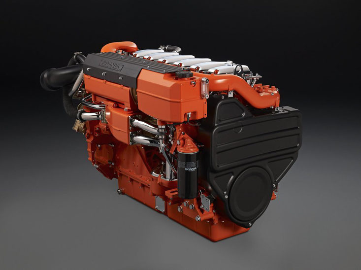
Operator’s manual
DC13 XPI Industrial engine
en-GB 2 893 529
Issue 11.0
IMPORTANT!
The owner is responsible for making sure that maintenance is carried out on time and in accordance with
the instructions.
The owner must entrust the maintenance, renewal and repair of emission-related components and systems
to a qualified workshop or person.
Summary of Contents for Scania DC13 XPI
- Manuals
- Brands
- Scania Manuals
- Engine
- DC13 XPI
Manuals and User Guides for Scania DC13 XPI. We have 2 Scania DC13 XPI manuals available for free PDF download: Operator’s Manual
Scania DC13 XPI Operator’s Manual (117 pages)
Brand: Scania
|
Category: Engine
|
Size: 5.46 MB
Table of Contents
-
Table of Contents
2
-
Start of Warranty
3
-
Engines
4
-
Emission Control Systems Warranty
4
-
Emission Control System Warranty Statement
4
-
General Warranty Provisions
4
-
Warranty Period
4
-
Parts Covered by the Warranty
5
-
General Warranty Limitations
6
-
Specific Warranty Exclusions
7
-
Customer Support
7
-
California Emission Control Warranty Statement
8
-
Your Warranty Rights and Obligations
8
-
Manufacturer’s Warranty Coverage
8
-
Owner’s Warranty Responsibilities
8
-
SCR Catalytic Converter
9
-
Introduction
11
-
Certification
11
-
Power Classes
12
-
Environment and Safety
13
-
Environmental Responsibility
13
-
Safety
13
-
Warnings and Advisories
14
-
Engine Data Plate
20
-
Component Identification
21
-
Engine
21
-
Exhaust Gas Aftertreatment Management System
22
-
Starting and Running
24
-
Checks before First Start
24
-
Checks before Running
25
-
Starting the Engine
26
-
Running
26
-
Engine Shutdown
34
-
Checks after Running
34
-
Transporting Engines
35
-
Maintenance
36
-
Cleaning the Engine
38
-
Engines with few Hours of Operation
39
-
Maintenance Interval
40
-
Lubrication System
43
-
Oil Grade
43
-
Oil Analysis
46
-
Checking the Oil Level
47
-
Maximum Angles of Inclination During Operation
47
-
Changing the Oil
48
-
Cleaning Upwards-Moving Centrifugal Oil Clean
49
-
Operational Testing of the Centrifugal Oil Cleaner
53
-
Renewing the Rotor in Downwards-Moving Cen
54
-
Trifugal Oil Cleaner
54
-
Renewing the Oil Filter
57
-
Air Cleaner
58
-
Reading the Vacuum Indicator
58
-
Renewing the Air Cleaner Filter Element and Safety Cartridge
59
-
Cooling System
60
-
Coolant
60
-
Checking the Coolant Level
67
-
Checking the Coolant’s Antifreeze and Corrosion Protection
68
-
Changing the Coolant and Cleaning the Cooling
70
-
System
70
-
Fuel System
79
-
Cleanliness Requirements
79
-
Checking the Fuel Level
80
-
Renewing the Fuel Filters
81
-
Venting the Fuel System
86
-
Miscellaneous
88
-
Checking the Drive Belt
88
-
Checking for Leakage
89
-
Checking and Adjusting the Valve Clearance
90
-
Renewing the Reductant Filter
93
-
Cleaning the Reductant Tank Filler Filter
96
-
Cleaning the Reductant Tank Ventilation Filter.96
96
-
Renewing the Particulate Filter
97
-
Quality Requirements for Fuel
103
-
Diesel
103
-
Biodiesel (FAME)
106
-
Hvo
107
-
Gtl
107
-
Reductant for SCR
108
-
Preparing the Engine for Storage
109
-
Preservative Products
109
-
Preparations for Storage
110
-
Technical Data
113
-
General Data
113
-
Lubrication System
113
-
Intake System
114
-
Cooling System
114
-
Fuel System
114
-
Electrical System
114
-
Scania Assistance
115
-
General Tightening Torques for Screw Joints
116
-
Hexagon Screws, Hexagon Socket Screws, Torx Screws, Hexagon Nuts
116
-
Flange Screws with Hexagonal Head and Hexago- Nal Flange Nuts
116
-
Hose Clamps
117
Advertisement
Scania DC13 XPI Operator’s Manual (83 pages)
Brand: Scania
|
Category: Engine
|
Size: 2.98 MB
Table of Contents
-
Start-Up Report — Warranty
3
-
Table of Contents
4
-
Introduction
5
-
Environment and Safety
6
-
Environmental Responsibility
6
-
Safety
6
-
Warnings and Advisories
7
-
Certification
12
-
-
Engines
13
-
Emission Control Systems Warranty
13
-
Emission Control System Warranty Statement
13
-
General Warranty Provisions
13
-
Warranty Period
13
-
Parts Covered by the Warranty
14
-
General Warranty Limitations
15
-
Specific Warranty Exclusions
16
-
Customer Support
16
-
-
California Emission Control Warranty Statement
17
-
Your Warranty Rights and Obligations
17
-
Manufacturer’s Warranty Coverage
17
-
Owner’s Warranty Responsibilities
17
-
-
SCR Catalytic Converter
18
-
Engine Data Plate
20
-
Component Identification
21
-
SCR System
22
-
-
Starting and Running
24
-
Checks before Running
24
-
Starting the Engine
24
-
Running
25
-
Engine Shutdown
28
-
Checks after Running
28
-
-
Inspection
29
-
Engines with few Hours of Operation
30
-
Cleaning the Engine
30
-
Inspection Interval
31
-
-
Lubrication System
32
-
Oil Grade
32
-
Oil Analysis
33
-
Checking Oil Level
33
-
Changing the Oil
34
-
Labels for Top-Up Engine Oil Grade
35
-
Parts
35
-
Cleaning the Centrifugal Oil Cleaner
36
-
Operational Testing
41
-
Renewing the Oil Filter
42
-
-
Cooling System
43
-
Coolant
43
-
Checking Coolant Level
47
-
Checking Antifreeze and Corrosion Inhibitor
48
-
Antifreeze and Corrosion Inhibitor
49
-
Changing Coolant
50
-
Cleaning the Cooling System
52
-
-
Air Cleaner
55
-
Reading the Vacuum Indicator
55
-
Renewing the Filter Element
55
-
Renewing the Safety Cartridge
56
-
-
Fuel System
57
-
General Information on the XPI Fuel System
57
-
Checking Fuel Level
57
-
Renewing the Fuel Filter
58
-
Bleeding the Fuel System
62
-
-
Miscellaneous
63
-
Checking the Drive Belt
63
-
Checking for Leaks
65
-
Checking and Adjusting the Valve Clearance
65
-
Renewing the Reductant Filter
68
-
Cleaning the Reductant Tank Filler Filter
70
-
Cleaning the Reductant Tank Ventilation Filter.69
70
-
-
Diesel
70
-
Composition of the Fuel
70
-
Sulphur Content of Fuel
71
-
Temperature Dependency of the Fuel
73
-
-
Reductant for SCR
74
-
Responsibility and Quality Requirements
74
-
Properties
75
-
-
Preparing the Engine for Storage
76
-
Handling the Engine
76
-
Preservative Coolant
77
-
Preservative Fuel
77
-
Preservative Oil
78
-
Preparations for Storage
78
-
-
Technical Data
81
-
General Data
81
-
Lubrication System
81
-
Injection System
82
-
Cooling System
82
-
Intake System
82
-
Electrical System
82
-
-
Scania Assistance
83
Advertisement
Related Products
-
Scania DC13 073A
-
Scania DC13 074
-
Scania DC13 072A
-
Scania DC13 077
-
Scania DC13 085
-
Scania DC13 078
-
Scania DC13 081
-
Scania DC13 080
-
Scania DC13 070A
-
Scania DC13 076
Scania Categories
Engine
Car Receiver
Automobile Accessories
![]()
Monitor
Receiver
More Scania Manuals
![]()
INSTALLATION
MANUAL
Exhaust system
Industrial engines
DC09, DC13, DC16
333 380
© Scania CV AB 2016, Sweden
Downloaded from www.Manualslib.com manuals search engine

|
INSTALLATION |
|
|
MANUAL |
|
|
Sound reduction…………………………………………………………………………………………. |
3 |
|
Exhaust noise…………………………………………………………………………………………. |
3 |
|
Exhaust system design ……………………………………………………………………………. |
5 |
|
Connection of exhaust system to engine ………………………………………………………. |
9 |
|
V-clamp………………………………………………………………………………………………… |
9 |
|
Stage III B/Tier 4i and less restrictive emission laws ………………………………… |
10 |
|
Stage IV/Tier 4f……………………………………………………………………………………. |
16 |
|
Exhaust back pressure ……………………………………………………………………………… |
18 |
|
Exhaust back pressure for all engine types ………………………………………………. |
18 |
|
Exhaust back pressure Stage III B/Tier 4i………………………………………………… |
19 |
|
Exhaust back pressure for Stage IV/Tier 4f ……………………………………………… |
20 |
|
Measuring exhaust back pressure……………………………………………………………. |
21 |
|
Insulating the exhaust system……………………………………………………………………. |
24 |
|
Insulation of SCR components……………………………………………………………….. |
25 |
|
Insulation of Stage IV/Tier 4f engines …………………………………………………….. |
25 |
|
Protection against water ingress ……………………………………………………………….. |
27 |
|
Multi-engine installation…………………………………………………………………………… |
28 |
|
Dimensioning the exhaust system ……………………………………………………………… |
30 |
|
Calculation example……………………………………………………………………………… |
31 |
© Scania CV AB 2016, Sweden
Downloaded from www.Manualslib.com manuals search engine

INSTALLATION
MANUAL
Sound reduction
Sound reduction
Assess the need for sound reduction in new installations from case to case, based on the applicable conditions in relation to noise requirements, length and type of exhaust system, location of the exhaust system outlet etc.
Some form of sound reduction is required in most installations.
The thermal insulation of the exhaust system affects the sound level. A thermally insulated system can result in a higher noise level than an uninsulated system.
This document contains information on SCR components. More detailed information on the SCR system can be found in the SCR system installation manual.
Exhaust noise
The table shows undamped exhaust noise measured 1 metre after the turbocharger at full power output.
|
Engine |
Power (kW) |
Engine speed (rpm) |
Sound level (dBA) |
Most important one-third octave |
|
bands (Hz) |
||||
|
DC09 |
202-243 |
1,500 |
115 |
63 and 125 |
|
1,800 and 2,100 |
117 |
80 and 160 |
||
|
257-294 |
1,500 |
117 |
63 and 125 |
|
|
1,800 and 2,100 |
119 |
80 and 160 |
||
|
DC13 |
257-316 |
1,500 |
115 |
80 and 160 |
|
1,800 and 2,100 |
117 |
100 and 200 |
||
|
331-405 |
1,500 |
118 |
80 and 160 |
|
|
1,800 and 2,100 |
120 |
100 and 200 |
© Scania CV AB 2016, Sweden
Downloaded from www.Manualslib.com manuals search engine

INSTALLATION
MANUAL
Sound reduction
|
Engine |
Power (kW) |
Engine speed (rpm) |
Sound level (dBA) |
Most important one-third octave |
|
bands (Hz) |
||||
|
DC16 |
405 |
1,500 |
116 |
100 and 200 |
|
1,800 and 2,100 |
119 |
125 and 250 |
||
|
478-515 |
1,500 |
118 |
100 and 200 |
|
|
1,800 and 2,100 |
121 |
125 and 250 |
The most important frequency range for exhaust noise is between 50 and 500 Hz. The exhaust flow in the system can generate hissing sounds, e.g. at sharp bends and edges. This phenomenon occurs higher up in the frequency range and is effectively dampened with an absorption silencer (e.g. glass fibre).
Vibrations in the silencer casing can also generate noise. For this reason, avoid silencers with flat surfaces.
© Scania CV AB 2016, Sweden
Downloaded from www.Manualslib.com manuals search engine

INSTALLATION
MANUAL
|
Exhaust system design |
L(m) |
|||||||||
|
Position the silencer as close to the end of the exhaust system as possible. In order to |
2.0 |
|||||||||
|
obtain the best noise reduction, there should only be a short tailpipe after the silencer |
1 |
|||||||||
|
(0.8-1.5 m) as shown in the chart. |
1.8 |
|||||||||
|
• For all-speed engines, read the specified maximum speed for the engine. |
||||||||||
|
• For single-speed engines, read the operating speed of the engine. |
1.6 |
2 |
||||||||
|
If the silencer cannot be positioned close to the exhaust system outlet because of a |
1.4 |
|||||||||
|
lack of space, it should be placed as close to the engine as possible. This location is, |
||||||||||
|
however, unfavourable in silencing terms if the pipes beyond it are long. It may be |
||||||||||
|
advisable to install another silencer near to the outlet. |
1.2 |
|||||||||
|
Note: |
3 |
|||||||||
|
1.0 |
||||||||||
|
Sharp exhaust pipe bends close to the outlet increase the risk of hissing sounds. |
||||||||||
|
0.8 |
||||||||||
|
Exhaust outlet |
||||||||||
|
1200 |
1500 |
1800 |
2100 |
|||||||
|
Design the exhaust system so that the exhaust gases are not reflected against vertical |
Graph for determining the longest length of tailpipe. |
|||||||||
|
walls, since this results in increased noise level. |
||||||||||
|
1. DCI9. |
||||||||||
|
Position the exhaust outlet so that no exhaust gases can be drawn into the engine in- |
2. DC13. |
|||||||||
|
take. If exhaust gases are drawn into the intake, intake air temperature increases rap- |
3. DC16. |
idly. The exhaust gases contain soot particles so there is also a risk of the air filter becoming blocked.
 WARNING!
Position the exhaust outlet so that exhaust gases cannot penetrate areas occupied by people, e.g. residential buildings.
01:04 Issue 10 en-GB
© Scania CV AB 2016, Sweden
Downloaded from www.Manualslib.com manuals search engine

INSTALLATION
MANUAL
Example
If 2 silencers are used in the system, they should be positioned in series at a distance of 2/3 of the length of the tailpipe and with the silencer used to dampen high-frequen- cy noise furthest away from the engine.
Since the pipes which form part of an exhaust system also operate as silencers, it is important that they are dimensioned correctly.
Note:
The exhaust back pressure increases with the number of pipe bends and with increased pipe length. This leads to higher fuel consumption and loss of power.
 IMPORTANT!
The installer is responsible for ensuring that the exhaust system is well sealed during installation. He is also responsible for ensuring that the pipe and silencer suspension is designed in such a way that system leaks cannot arise during operation.
01:04 Issue 10 en-GB
© Scania CV AB 2016, Sweden
Downloaded from www.Manualslib.com manuals search engine

INSTALLATION
MANUAL
Examples of long exhaust systems (i.e. longer than 5 metres) with designs which aid sound reduction.
Examples of short exhaust systems with designs which aid sound reduction.
L = Length of tailpipe, determined from graph.
a = 2/3 of L. Length a is less significant in exhaust systems with only one silencer.
|
a |
L |
|||||||
 a
a
L
L
a
Sound reduction
338 554 338 555
338 556
338 557
338 558
© Scania CV AB 2016, Sweden
Downloaded from www.Manualslib.com manuals search engine

INSTALLATION
MANUAL
|
SCR system |
1 |
2 |
3 |
|
|
For engines with an SCR system, in most cases the exhaust system needs to be sup- |
||||
|
plemented by a silencer. |
||||
|
More information on the positioning of SCR components can be found in the SCR |
a |
|||
|
system installation manual. |
||||
|
1. |
Oxidation catalytic converter. |
|||
|
2. |
Evaporator or hydrolysis catalytic converter. |
|||
|
3. |
SCR catalytic converter. |
|||
|
4. |
Silencer. |
Oxidation catalytic converter
The oxidation catalytic converter provides a sound reduction of approximately
1.5 dB from 500 Hz and higher frequencies. At lower frequencies, the oxidation catalytic converter has no sound reducing effect.
01:04 Issue 10 en-GB
© Scania CV AB 2016, Sweden
Sound reduction
4
 L
L 
 506337
8
Downloaded from www.Manualslib.com manuals search engine

INSTALLATION
MANUAL
Connection of exhaust system to engine
Connection of exhaust system to engine
There should always be a flexible connection between the exhaust system and the engine which absorbs the movement of the engine and changes in length in the exhaust system due to temperature changes. A flexible connection can consist of the Scania exhaust bellows. Position the flexible connection as close to the turbocharger connection as possible.
 IMPORTANT!
The weight of the exhaust system must not load the exhaust bellows or turbocharger. Therefore, place a suspension point immediately after the flexible connection.
The illustration to the right shows the recommended installation of the exhaust system.
If the exhaust pipes are very long or if the exhaust system has a relatively long horizontal part between 2 vertical parts, several flexible connections may be required in the system. There must then be a fixed anchorage point on one side of the vertical exhaust bellows and a suspension which allows axial movement on the other side.
5


 4
4


 3 1 2
3 1 2 

369 3 11
Recommended installation of exhaust system.
1.Turbocharger.
2.Exhaust pipe bend.
3.Exhaust bellows.
4.Exhaust pipe.
5.Bracket.
V-clamp
Scania pipe sections have flanges secured with V-clamps.
Note:
The V-clamp must not be used to force together joints, but only to fix the flanges.
|
338 567 |
|||
|
01:04 Issue 10 en-GB |
9 |
||
|
© Scania CV AB 2016, Sweden |
Downloaded from www.Manualslib.com manuals search engine

INSTALLATION
MANUAL
Connection of exhaust system to engine
Stage III B/Tier 4i and less restrictive emission laws
Exhaust pipe bends
The engines can be equipped with a 90° exhaust pipe bend on the turbocharger exhaust outlet. The exhaust pipe bend can be fitted at different angles and rotated 360° around the connection with the turbocharger.
The exhaust pipe bend is connected to the turbocharger with a V-clamp.
The exhaust pipe bend outlet has a flange that is connected with a V-clamp. It is usually connected directly to the Scania exhaust bellows.
|
100 |
148 |
||
|
Ø185.3 |
|||
|
Ø185.3 |
|||
|
Exhaust pipe bends for DC09 and DC13 |
|||
|
1. |
DC09 071A. |
||
|
2. |
Other DC09 engines and DC13 072/073A. |
195 |
|
|
175 |
|||
|
1 |
2 |
335 011 |
© Scania CV AB 2016, Sweden
Downloaded from www.Manualslib.com manuals search engine
 Loading…
Характеристики
Технические характеристики
Основная (номинал.) мощность 1
365 кВт
Резервная (макс.) мощность 2
403 кВт
Тип двигателя
дизельный, 4-тактный
Рабочий объём двигателя
12,7 л
Число, расположение цилиндров
6, рядное
Порядок работы цилиндров
1-5-3-6-2-4
Диаметр цилиндра / ход поршня
130 x 140 мм
Номинальная частота вращения
1500 мин -1
Система управления двигателем
электронная — Scania EMS,
с поддержкой CAN-шины
Система впрыска топлива
прямой впрыск, насос-форсунки Scania PDE с электронным управлением
Вид наддува воздуха
турбонаддув с интеркулером типа «воздух-воздух»
Система охлаждения
жидкостная
Отбор мощности на вентилятор
10 кВт
Шаг приема нагрузки (step-load, G2), отн. основной мощности
69 %
Номинальное напряжение электрической системы
24 В
Удельный расход топлива 3 :
при 100% ном. мощности
183 г/кВт*ч
при 75% ном. мощности
184 г/кВт*ч
при 50% ном. мощности
186 г/кВт*ч
Расход масла на угар, при 100% мощности:
Относительно расхода топлива
0 %
Удельный расход масла
0,3 г/кВт*ч
Заправочные емкости:
Система охлаждения 4
45 л
Стандартный период замены масла 5
500 моточасов
Габариты (Д х Ш х В)
1519 х 860 х 1223 мм
Масса (без масла и охл. жидкости)
1050 кг
Ресурс до капитального ремонта
40000 моточасов
Стандартное оборудование 6
Топливная система:
- прямой впрыск, насос-форсунки Scania PDE с электронным управлением
- топливный фильтр предварительной очистки с влагоотделителем (10 микрон)
- топливный фильтр тонкой очистки (6 микрон)
Система смазки двигателя:
- насос системы смазки двигателя
- масляный фильтр, полнопоточный
- центробежный маслоочиститель (5-7 микрон)
- охладитель масла, интегрированный в блок
Воздушная и газовыхлопная система:
- воздухоочиститель с индикатором засоренности воздушного фильтра
- турбокомпрессор с перепускным электромагнитным клапаном и интеркулером
- защита на выпускном коллекторе
Система охлаждения:
- радиатор жидкостного охлаждения
- охладитель наддувочного воздуха типа «воздух – воздух»
- вентилятор толкающего типа диаметром 914 мм с защитной решеткой
- водяной насос, термостат
Электрооборудование:
- электронная система управления двигателем Scania EMS, с поддержкой CAN-шины (протокол SAE J1939), отвечающая ISO 8528-5 класс G3
- стартер, 1-полюсный, 24 В, мощностью 6 кВт
- электрогенератор, 1-полюсный, 28 В, 100 А
- встроенный жидкостный подогреватель 220В
- датчик давления масла
- датчики температуры и уровня охлаждающей жидкости
- датчик частоты вращения двигателя
- датчик температуры и давления наддувочного воздуха
1 Основная мощность (Prime power) – номинальная мощность (при 1500 об./м) для непрерывной работы дизельного двигателя Scania DC13 072A (365 kW) при различных нагрузках в соответствии с ISO 8528-1. Maкс. средний фактор нагрузки — 70% от указанной основной мощности за каждый 24-х часовой интервал. 1 час в течение каждого 12 часового интервала допускается нагрузка до 110% основной мощности.
2 Резервная мощность (Stand-by power) — для работы дизельного двигателя Scania DC13 072A (365 kW) при нормальном изменении нагрузки в течение перерыва подачи электроэнергии в соответствии с ISO 8528-1. Maкс. средний фактор нагрузки — 70% от указанной резервной мощности за каждый 24-х часовой интервал. Годовая наработка не должна превышать 200 моточасов. Перегрузка не допускается.
3 Удельный расход топлива указан при плотности дизельного топлива 0,84 кг/л.
4 Объем системы жидкостного охлаждения двигателя Scania DC13 072A (365 kW) указан с учетом радиатора, патрубков и расширительного бачка.
5 Период замены моторного масла в зависимости от условий эксплуатации двигателя Scania DC13 072A (365 kW) (например, при повышенной загрязненности окружающего воздуха) может снижаться – обязательно проверяйте рекомендации производителя двигателя по периодичности проведения ТО.
6 Оборудование дизельного двигателя Scania DC13 072A (365 kW) приводится в объеме, устанавливаемом ООО «Компания Дизель» в составе готовой дизельной электростанции. Комплектация двигателя Scania DC13 072A (365 kW), поставляемого производителем, может отличаться.
|
Title |
File Size |
Download Links |
|
Parts Catalogue DI 16 Marine Engines.pdf |
17.6Mb |
Download |
|
Scania 16-litre engine marine engines Workshop Manual.pdf |
7Mb |
Download |
|
Scania DC09, DC13, DC16 Industrial engines — Electrical system.pdf |
2.8Mb |
Download |
|
Scania DC12 Operator’s Manual.pdf |
2Mb |
Download |
|
Scania DI09, DI13, DI16 Marine engines — CAN interface.pdf |
3.9Mb |
Download |
|
Scania DI09, DI13, DI16 Marine engines — Electrical System Issue 7.pdf |
3.3Mb |
Download |
|
Scania DI09, DI13, DI16 Marine engines — Electrical system.pdf |
2.8Mb |
Download |
|
Scania DI09, DI13, DI16 Marine engines — Fault codes DM1.pdf |
621kb |
Download |
|
Scania DI09, DI13, DI16 Marine engines — Instrumentation 2.0.pdf |
22.3Mb |
Download |
|
Scania DI13, DI16 Marine engines — SCR system.pdf |
3Mb |
Download |
|
Scania DI14 82 Operator’s Manual.pdf |
1.2Mb |
Download |
|
Scania DI16 XPI series Operator’s Manual.pdf |
4.9Mb |
Download |
|
Scania DI9 Operator’s Manual.pdf |
1.2Mb |
Download |
|
Scania marine engines DATA HANDBOOK.pdf |
19.9Mb |
Download |
|
Scania marine engines DI09, DI13, DI16 Installation Manual.pdf |
5.9Mb |
Download |
|
Scania marine engines DI09, DI13, DI16 Technical data.pdf |
3Mb |
Download |
|
Scania marine engines DI16 EMS with S6/PDE Operator’s Manual.pdf |
3.4Mb |
Download |
Scania has been manufacturing marine engines for over a hundred years. The accumulated experience allows us to create reliable, compact and economical in operation marine diesel
engines.
They cope with any task: from pushing a loaded barge upstream to the rotation of the propeller of a speedboat. Scania engines have become an obvious choice for those who want to
reduce fuel consumption without sacrificing performance.
Scania marine engines are approved by all leading classification societies, including the Russian Maritime and River Registers.
The Scania engine range includes 9, 13 and 16 liter engines from 220 to 1000 hp.
All Scania engines comply with IMO Tier II emission standards.
Three Scania marine engine models are currently available: the in-line 9-liter Scania DI 09M engine (162-294 kW), the in-line 13-liter Scania DI 13 M
engine (294-551 kW) and the 16-liter Scania DI V-engine 16M (405-882 kW). Depending on the rating, Scania engines can be used for work boats, speed boats and yachts.