
Ярославскими двигателями оснащаются более 300 моделей транспортных средств и изделий специального назначения, производимых предприятием России и Белоруссии.
Двигатели ЯМЗ устанавливаются на грузовые автомобили, магистральные автопоезда, карьерные самосвалы, автобусы, тракторы и зерноуборочные комбайны, строительно-дорожную технику,
а также на дизель-электрические станции.
Вся продукция ЯМЗ продается в фирменной упаковке с эмблемой ЯМЗ подтверждающей подлинность изделья и гарантирует высочайшее качество!
В данном разделе предоставлена техническая информация, бюллетени, информационные письма от завода ПАО Автодизель
6,76 Мб
Двигатели ЯМЗ-238Б, ЯМЗ-238БЕ, ЯМЗ-238БЕ2, ЯМЗ-238Д,
Формат: pdf
-
Год:
2010
-
Страниц:
354
-
Язык:
русский
-
Размер:
6,76 Мб
-
Категории:
Двигатели ЯМЗ
3,52 Мб
Руководство по эксплуатации двигателей ЯМЗ-650, ЯМЗ-6501,
Формат: pdf
-
Год:
2008
-
Страниц:
113
-
Язык:
русский
-
Размер:
3,52 Мб
-
Категории:
Двигатели ЯМЗ
10,6 Мб
Руководство по эксплуатации двигателей ЯМЗ-7511.10,
Формат: pdf
-
Год:
2017
-
Страниц:
337
-
Язык:
русский
-
Размер:
10,6 Мб
-
Категории:
Двигатели ЯМЗ
3,05 Мб
Каталог запчастей дизельных двигателей ЯМЗ-7511.10,
Формат: pdf
-
Год:
2005
-
Страниц:
154
-
Язык:
русский, английский
-
Размер:
3,05 Мб
-
Категории:
Двигатели ЯМЗ
28,4 Мб
Руководство по ремонту двигателя ЯМЗ-651 Евро 4
Формат: pdf
-
Год:
2012
-
Страниц:
154
-
Язык:
русский
-
Размер:
28,4 Мб
-
Категории:
Двигатели ЯМЗ
6,4 Мб
Двигатели ЯМЗ-536, ЯМЗ-5361, ЯМЗ-5362, ЯМЗ-5363, ЯМЗ-5364:
Формат: pdf
-
Год:
2016
-
Страниц:
285
-
Язык:
русский
-
Размер:
6,4 Мб
-
Категории:
Двигатели ЯМЗ
3,85 Мб
Руководство по эксплуатации двигателей ЯМЗ-850.10,
Формат: pdf
-
Год:
2008
-
Страниц:
150
-
Язык:
русский
-
Размер:
3,85 Мб
-
Категории:
Двигатели ЯМЗ
6,8 Мб
Двигатели ЯМЗ-5340, ЯМЗ-5341, ЯМЗ-5342, ЯМЗ-5344:
Формат: pdf
-
Год:
2016
-
Страниц:
161
-
Язык:
русский
-
Размер:
6,8 Мб
-
Категории:
Двигатели ЯМЗ
9,47 Мб
Руководство по эксплуатации БелАЗ-7547 и его модификаций
Формат: pdf
-
Год:
2007
-
Страниц:
276
-
Язык:
русский
-
Размер:
9,47 Мб
-
Категории:
Двигатели ЯМЗ
13,5 Мб
Руководство по эксплуатации автогрейдеров ЧСДМ ДЗ-98В
Формат: pdf
-
Год:
2018
-
Страниц:
119
-
Язык:
русский
-
Размер:
13,5 Мб
-
Категории:
Двигатели ЯМЗ
2,93 Мб
Техническое обслуживание и ремонт однодисковых сцеплений с
Формат: pdf
-
Год:
2005
-
Страниц:
63
-
Язык:
русский
-
Размер:
2,93 Мб
-
Категории:
Двигатели ЯМЗ
1,66 Мб
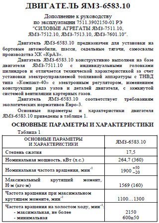
Руководство по эксплуатации двигателей ЯМЗ-6583.10
Формат: pdf
-
Год:
2012
-
Страниц:
57
-
Язык:
русский
-
Размер:
1,66 Мб
-
Категории:
Двигатели ЯМЗ
1,83 Мб
Руководство по эксплуатации двигателей ЯМЗ-6562.10 и
Формат: pdf
-
Год:
2012
-
Страниц:
68
-
Язык:
русский
-
Размер:
1,83 Мб
-
Категории:
Двигатели ЯМЗ
1,4 Мб
Руководство по эксплуатации двигателя ЯМЗ-6561.10
Формат: pdf
-
Год:
2012
-
Страниц:
46
-
Язык:
русский
-
Размер:
1,4 Мб
-
Категории:
Двигатели ЯМЗ
3,1 Мб
Ремонт двигателей ЯМЗ-236 и ЯМЗ-238
Формат: djvu
-
Год:
1974
-
Страниц:
216
-
Язык:
русский
-
Размер:
3,1 Мб
-
Категории:
Двигатели ЯМЗ
5,32 Мб
Руководство по эксплуатации двигателей ЯМЗ-236М2 и ЯМЗ-238М2
Формат: pdf
-
Год:
2010
-
Страниц:
172
-
Язык:
русский
-
Размер:
5,32 Мб
-
Категории:
Двигатели ЯМЗ
34,3 Мб
Устройство и ремонт двигателей ЯМЗ-7511.10, ЯМЗ-7512.10,
Формат: pdf
-
Год:
2007
-
Страниц:
329
-
Язык:
русский
-
Размер:
34,3 Мб
-
Категории:
Двигатели ЯМЗ
17 Мб
Руководство по ремонту двигателя ЯМЗ-650
Формат: pdf
-
Год:
2009
-
Страниц:
134
-
Язык:
русский
-
Размер:
17 Мб
-
Категории:
Двигатели ЯМЗ
5,1 Мб
Ремонт двигателей ЯМЗ-240, ЯМЗ-240Н и ЯМЗ-240Б
Формат: djvu
-
Год:
1978
-
Страниц:
311
-
Язык:
русский
-
Размер:
5,1 Мб
-
Категории:
Двигатели ЯМЗ

73 Мб
Каталог запчастей двигателей ЯМЗ-236, ЯМЗ-238, ЯМЗ-240 и их
Формат: exe
-
Год:
2009
-
Язык:
русский
-
Размер:
73 Мб
-
Категории:
Двигатели ЯМЗ
Каталог запчастей двигателей ЯМЗ-236, ЯМЗ-238, ЯМЗ-240, ЯМЗ-7511, ЯМЗ-7601, ЯМЗ-8401, ЯМЗ-8421, ЯМЗ-8424, ЯМЗ-850 и их модификаций дает представление о 32 различных модификациях дизелей, производимых ярославским предприятием.
1 2
Только оригинальные руководства
Доступно сразу после оплаты
Полное соответствие бумажным изданиям
100% защита ваших оплат
Издательство: © «Motorist»
ISBN: 977-272-145-687-6
Количество страниц: 133
Формат: файл PDF
О руководстве
Тип двигателя: ЯМЗ 5340 / ЯМЗ 536
В руководстве вы найдете
- Пошаговое руководство по ремонту различных узлов и агрегатов
- Инструкцию по самостоятельному уходу и обслуживанию
- Сведения о конструкции двигателя и о том как предупредить неисправность
- Информацию для поездки на СТО, если самостоятельный ремонт невозможен
Содержание
Введение
Сокращения, принятые в тексте
Устройство электронной системы управления двигателем (ЭСУД)
- Общее описание
- Общее устройство и принцип работы ЭСУД
- Электронный блок управления (ЭБУ)
- Устройство и характеристика
- Интерфейсы связи
- Датчики контроля параметров работы двигателя
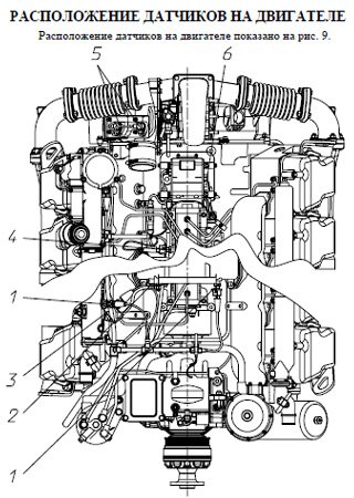
- Место установки датчиков
- Отказы датчиков
- Схема прокладки жгутов
- Датчики частоты вращения двигателя DG6
- Устройство и принцип работы датчика частоты вращения двигателя
- Датчик частоты вращения коленчатого вала
- Характеристика датчика
- Конфигурация разъёма
- Датчик частоты вращения распределительного вала
- Конфигурация разъёма
- Отказ датчиков частоты вращения двигателя
- Датчик давления и температуры наддувочного воздуха
- Характеристика датчика
- Конфигурация разъёма
- Отказ датчика давления и температуры наддувочного воздуха
- Датчик давления и температуры масла
- Характеристика датчика
- Конфигурация разъёма
- Отказ датчика давления и температуры масла
- Датчик давления и температуры топлива
- Конфигурация разъёма
- Отказ датчика давления и температуры топлива
- Датчик температуры охлаждающей жидкости
- Характеристика датчика
- Конфигурация разъёма
- Отказ датчика температуры охлаждающей жидкости
- Датчик давления топлива в рампе
- Характеристика датчика
- Конфигурация разъёма
- Отказ датчика давления в рампе
- Дозирующее устройство с электромагнитным клапаном
- Характеристика дозирующего устройства
- Конфигурация разъёма
- Отказ дозирующего устройства
- Система рециркуляции отработавших газов
- Заслонка отработавших газов
- Характеристика датчика положения заслонки EGR
- Конфигурация разъёма
- Отказ датчика положения заслонки EGR
- Клапан заслонки EGR
- Характеристика клапана заслонки EGR
- Конфигурация разъёма
- Отказ клапана заслонки EGR
- Датчик положения педали акселератора (электронная педаль)
- Устройство и принцип действия
- Характеристика электронной педали
- Конфигурация разъёма
- Отказ датчика положения педали акселератора
- Датчики, обеспечивающие безопасность движения ТС
- Датчик положения педали тормоза
- Отказ датчика положения педали тормоза
- Датчик положения педали сцепления (для механической КП)
- Отказ датчика положения педали сцепления
- Кнопка моторного тормоза
- Отказ кнопки моторного тормоза
- Датчик воды в топливе
- Отказ датчика воды в топливе
Система бортовой диагностики (БД)
- Описание системы бортовой диагностики двигателей семейства ямз-530
- Перечень компонентов электронной системы управления, контролируемых системой БД
- Системы и компоненты двигателя
- Топливная система
- Система ограничения оксидов азота
- Система ограничения выбросов «твердых» частиц
- Описание принципов работы системы БД
- Контроль системы ограничения оксидов азота
- Контроль системы ограничения вредных частиц
- Контроль системы топливоподачи
- Алгоритм для определения выбросов оксидов азота
- Ограничитель крутящего момента
- Описание ограничений по внешней скоростной характеристике
- Лампа сигнализации неисправностей в системе БД
- Датчики для контроля вредных веществ в отработавших газах системы БД
- Датчик температуры воздуха (система БД)
- Характеристика датчика температуры воздуха
- Конфигурация разъёма
- Отказ датчика температуры воздуха
- Датчик дифференциального давления (система БД)
- Характеристика датчика дифференциального давления
- Конфигурация разъёма
- Отказ датчика дифференциального давления
Диагностика двигателя
- Самоконтроль эсуд во время эксплуатации тс
- Устройства для оповещения о появлении неисправности
- Диагностическая лампа
- Просмотр диагностических кодов мигания
- Лампа сигнализации неисправностей системы БД
- Регистрация кодов неисправностей
- Обнаружение и устранение ошибок и неисправностей
- Работа двигателя при наличии активных диагностических кодов
- Работа двигателя с периодически возникающими диагностическими кодами
- Компьютерная диагностика двигателя
- Требования безопасности
- Порядок проведения компьютерной диагностики
- Коды неисправностей
- Поиск и устранение неисправностей
- Диагностика исполнительных механизмов
- Приложение А
- Рисунок А1 — схема электрическая принципиальная двигателя ЯМЗ-53601 с системой бортовой диагностики
- Приложение Б
- Таблица Б1 – коды неисправностей для двигателей без системы бортовой диагностики
- Таблица Б2 – коды неисправностей для двигателей с системой бортовой диагностики
Написать отзыв
Ваше Имя:
Ваш отзыв:
Оценка:
Отзывы покупателей
Нет отзывов об этом товаре.
Моторостроительное предприятие из Ярославля
Ярославский завод создан как предприятие по выпуску автомобилей в 1916 году русским инженером и промышленником В. А. Лебедевым. Происходившие в тот период события не позволили приступить к выпуску автомашин, и завод первоначально занимался только ремонтом. В 1926 году организован Ярославский автомобильный завод, который после масштабной реконструкции приступил к выпуску первых отечественных большегрузных самосвалов. В дальнейшем кроме грузовых автомашин грузоподъемностью до 8 тонн автозавод выпускал троллейбусы, автобусы и шасси.
В послевоенный период предприятие освоило выпуск дизельных двигателей серии ЯАЗ моделей 204 и 206 (110-220 л. с.) и изготовление трехосных мощных грузовиков ЯАЗ-210 (6Х4) грузоподъемностью до 12 тонн. Очередные изменения на заводе произошли в 1951 году. Именно тогда он был полностью перепрофилирован для изготовления дизельных силовых агрегатов различного применения, сцеплений и коробок передач для агрегатирования с выпускаемыми двигателями. Предприятие получило наименование «Ярославский моторный завод».
В настоящее время ЯМЗ («Автодизель») входит в автомобилестроительное объединение «Группа ГАЗ».
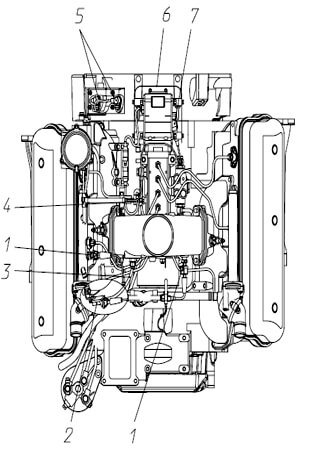
Схема расположения узлов двигателя

Схема двигателя ЯМЗ-536. Вид справа
1
. смотровой лючок механизма проворота коленчатого вала;
2
. датчик частоты вращения коленчатого вала;
3
. датчик давления и температуры масла;
4
. управление заслонкой рециркуляции отработавших газов EGR;
5
. датчик температуры охлаждающей жидкости;
6
. система вентиляции картера;
7
. турбокомпрессор;
8
. датчик давления и температуры наддувочного воздуха;
9
. пневмоклапан управления заслонкой EGR;
10
. фильтр масляный;
11
. пневмоклапан управления заслонкой моторного тормоза;
12
. стартер.

Схема двигателя ЯМЗ-536. Вид спереди
1
. крышка маслозаливная;
2
. датчик давления и температуры наддувочного воздуха;
3
. вязкостная муфта включения вентилятора;
4
. фильтр тонкой очистки топлива.

Схема двигателя ЯМЗ-536. Вид слева
1
. датчик давления и температуры топлива;
2
. место установки заводской таблички;
3
. гаситель крутильных колебаний;
4
. генератор;
5
. компрессор кондиционера;
6
. реле предпускового подогревателя;
7
. топливные трубки высокого давления;
8
. рампа;
9
. электронный блок управления;
10
. насос топливный высокого давления;
11
. датчик частоты вращения распределительного вала;
12
. компрессор пневмотормозов;
13
. насос гидроусилителя руля (НГУР);
14
. картер масляный;
15
. фильтр тонкой очистки топлива.
Особенности конструкции
Для достижения экологического уровня Евро-4 применена система EGR (рециркуляции отработавших газов) и каталитический нейтрализатор со сменным фильтром.
Система топливоподачи
Топливная система аккумуляторного типа (ECRS) производства фирмы R. Bosch. Система обеспечивает давление впрыска 1800 бар, включает в себя:
• насос высокого давления с модулем дозирования, • топливопровод-накопитель (рампа), • форсунки.
Система управления
Электронный блок управления (ЭБУ) EDC 7. Датчики системы управления и устройство коммутации:
• датчик частоты вращения, • датчик фазы, • датчик давления топлива, • датчик температуры топлива, • датчик температуры наддувочного воздуха, • датчик давления наддувочного воздуха, • датчик температуры охлаждающей жидкости, • датчик давления масла. Блок цилиндров, головка цилиндров, коленчатый вал, шатун, подшипники рассчитаны на давление сгорания 210 бар. Системы охлаждения и смазки спроектированы из условия обеспечения 40 кВт/л и имеют высокий потенциал дальнейшей форсировки. Шестеренчатый привод агрегатов расположен со стороны маховика и обеспечивает низкий уровень крутильных колебаний и шума не более 93 дБ (А). Закрытая система вентиляции картерных газов интегрирована в крышке головки цилиндров. Не требует обслуживания.
Опции
Предусмотрена возможность установки:
• компрессора пневмотормозов производительностью до 350 л/мин и до 500 л/мин; • насоса гидроусилителя рулевого управления; • компрессора кондиционера; • подсоединение предпускового подогревателя и отопителя кабины; • подсоединение системы охлаждения ретардера. Двигатель имеет возможность комплектования сцеплениями и коробками передач — по стандартам SAE 2, 3.

Развитие производства дизелей
В первое время после создания моторный завод продолжил выпуск двухтактных двигателей моделей 204 и 206. Одновременно с этим шла разработка новых перспективных дизельных агрегатов. Результатом такой работы стала серия двигателей ЯМЗ-236, 238, 240.
Новые моторы на начало выпуска считались современными и обладали высокими техническими характеристиками, которые обеспечили широкое применение указанным агрегатам. Они устанавливались на грузовики МАЗ, КРАЗ, ЗИЛ, УРАЛ, на бульдозеры, трактора, военную и строительную технику.

Главной особенностью указанных моторов считалось возрастание мощности за счет увеличения количества цилиндров. При этом существовала значительная унификация двигателей, обеспечивающая высокую ремонтопригодность указанных силовых агрегатов. В настоящее время после большого количества модернизаций предприятие продолжает выпуск данных двигателей практически в трехстах вариантах комплектации.
В начале семидесятых годов на предприятии было разработано и выпускалось семейство сверхмощных двигателей серии ЯМЗ-840 для автомобилей БЕЛАЗ, МоАЗ и спецтехники. В дальнейшем производство этих моторов было передано на Тутаевский завод.
Создание 530-й серии дизельных моторов
В начале двухтысячных годов компания приступила к разработке новых перспективных дизельных двигателей серии ЯМЗ-530, в рамках совместного проекта с австрийской группой AVL List. После успешных испытаний опытных образцов в 2012 году началось серийное производство двигателей ЯМЗ-534 и ЯМЗ-536.
За короткий период завод освоил свыше двухсот различных модификаций, а также комплектаций указанных моторов, что обеспечило их обширное использование. Новые силовые агрегаты обладали, в том числе и ЯМЗ-536, техническими характеристиками аналогичными, а иногда и превосходящими лучшие мировые моторы по следующим параметрам:
- наработка (ресурс);
- экологические стандарты (Евро-4; Евро-5);
- экономичность.

Особенностью устройства моторов является их адаптированность для эксплуатации в различных климатических условиях, в том числе многообразных отечественных. Кроме того, традиционно увеличенная унификация, несмотря на большое количество вариантов выпускаемых рядных двигателей ЯМЗ-536 (6 цилиндров) и 534 (4 цилиндра), удешевляет производство, а также повышает ремонтопригодность.
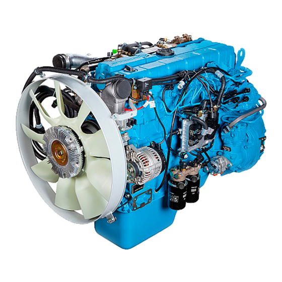
Новый современный 6-ти цилиндровый рядный двигатель начали выпускать в Ярославле в 2012 году и ставят его вместо ЯМЗ-656. Это совместная разработка Автодизеля и австрийской компании AVL List. Данный двигатель использует чугунный блок цилиндров с мокрыми гильзами из чугуна и с масляными форсунками. В блоке стоит коленчатый вал из стали с ходом поршня 128 мм (коренные шейки — 88 мм, шатунные шейки — 76 мм), стальные шатуны и поршни диаметром 105 мм. Это обеспечивает рабочий объем 6.65 литров.
На блоке установлена 16-клапанная чугунная головка. Впускные клапаны имеют диаметр 36 мм, а выпускные 34 мм. Распредвал по-прежнему установлен в блоке и вращается с помощью двух шестеренок. Регулировать клапаны нужно каждые 30 тыс. км, если это необходимо.Зазоры клапанов: впускные 0.3-0.4 мм, выпускные 0.4-0.5 мм.
Эти движки оснащаются впрыском Common rail с насосом Bosch СР3.3 NH-MD, давление впрыска — 1800 бар.Давление масла (прогретый двигатель): 4.1-6.5 кгс/см2.Данный мотор оснащается турбокомпрессором ТКР-80.05.12.
На 536-ом моторе стоит блок управления Bosch EDC7 UC31.
Ярославский 6-ти цилиндровый рядник имеет близкого родственника — ЯМЗ-534.
Модификации ЯМЗ 536 и их отличия
1. ЯМЗ-536 — базовый мотор под Евро-4 мощностью 312 л.с. при 2300 об/мин, крутящий момент 1226 Нм при 1300-1600 об/мин. Устанавливают на МАЗ-5363, 5440, 5550, 6312, 6501; Урал-6370, ЛиАЗ-5256, 6212, 6213. — ЯМЗ-53601 — аналог 536 с EOBD II. Устанавливается на МАЗ-5363, 5440, 5550, 6312, 6501; ЛиАЗ-5256, 6212, 6213. — ЯМЗ-53602 — версия 536-го с турбиной ТКР 80.05.13, без EGR, с другим впускным трактом и настройкой ЭБУ. Это версия под 4-й экологический класс (правила 96-02). Встречается на Урал-NEXT, 4320, 4420, 5557; катерах КС-162, 164, 165, 169, 950, 951, Флагман, Амета. — ЯМЗ-53603 — версия под Евро-5 с SCR-катализатором и EOBD II. Мощность возросла до 330 л.с. при 2300 об/мин, момент 1275 Нм при 1300-1600 об/мин. — ЯМЗ-53604 — аналог 536 для работы на газе. 2. ЯМЗ-5361 — такой же 536, но мощность снижена до 270 л.с. при 2300 об/мин, момент 1166 Нм при 1300-1600 об/мин. Устанавливается двигатель на МАЗ-5363, 5440, 5550, 6312 — ЯМЗ-53611 — тот же 5361, но с EOBD II. Шел движок на МАЗ-5363, 5440, 5550, 6312. — ЯМЗ-536111 — аналог 53611 для ЛиАЗ-5292 и 5293. — ЯМЗ-53613 — аналог ЯМЗ-536, но под нормы Евро-5. Модель оснащается SCR-катализатором и EOBD II. Стоит этот двс на ЛиАЗ-5256, 6212, 6213. 3. ЯМЗ-5362 — версия для Урал мощностью 240 л.с. при 2300 об/мин, момент 900 Нм при 1300-1600 об/мин. Мотор устанавливается на ЛиАЗ-5256, 5292, 5293; ЧСДМ ДЗ-98. — ЯМЗ-53621 — тот же 5362 с EOBD. — ЯМЗ-53622 — аналог 5362 с турбокомпрессором ТКР 80.05.13, измененным впуском и без клапана EGR. Делался двигатель под экологический класс 4 (правила 96-02). Устанавливается на Урал Next, 3255, 4320, 5557, 5831. — ЯМЗ-53623 — Евро-5 версия на 275 л.с. при 2300 об/мин и с моментом в 1177 Нм при 1300-1600 об/мин. — ЯМЗ-53624 — аналог 5362, работающий на газе и имеющий мощность 287 л.с. 4. ЯМЗ-5363 — версия для МАЗ и КрАЗ, ее отдача 240 л.с. при 2300 об/мин, крутящий момент 1049 Нм при 1300-1600 об/мин. Устанавливается на МАЗ-5363, 5550. — ЯМЗ-53631 — такой же 5363 с EOBD II. — ЯМЗ-53633 — Евро-5 модель на 276 л.с. для ЛиАЗ-5292. 5. ЯМЗ-5364 — мотор развивает 285 л.с. при 2300 об/мин, момент 1130 Нм при 1300-1600 об/мин. Встретить его можно на ЛиАЗ-6212 и 6213. — ЯМЗ-53642 — аналог 5364 без EGR, с ТКР 80.05.13 и с другим впуском. Заточен мотор под эко класс 4 и установлен на Урал-4320, 4420, 5551, 5831, 5557. — ЯМЗ-53644 — газовая версия на 260 л.с. — ЯМЗ-53645 — тракторный и комбайновый аналог 53642. — ЯМЗ-53646 — такой же 53642, но мощность снижена до 202 л.с. Предназначен для RM-Terex WX 200 и TX 270. 6. ЯМЗ-5366 — тракторная модель под экологический класс 4 (нормы 96-02) мощностью 262 л.с. Устанавливают на RM-Terex TG 200. — ЯМЗ-53662 — модификация 5366 на 219 л.с. для RM-Terex TG 180. — ЯМЗ-53663 — модель на 246 л.с. под Евро-5 для ЛиАЗ-5262, 5292, 5293. 7. ЯМЗ-5368 — версия для дизель-генераторов.
Неисправности ЯМЗ-536
Здесь нужно следить за состоянием ЕГР, где скапливается нагар и клапан клинит. Это решают или регулярной чисткой или заглушкой EGR и прошивкой ЭБУ под работу без этого клапана. Также мотор может расходовать масло. В этом случае проверяйте направляющие клапанов, они могут износиться, и через них будет поступать масло. Турбина служит примерно 250-300 тыс. км плюс-минус. К этому пробегу нужно контролировать ее состояние, чтобы мертвая турбина на потянула за собой другие расходы. В случае выхода турбокомпрессора из строя, желательно ставить аналог BorgWarner B2G. Бывают случаи поломки турбины даже до 50 тыс. км пробега. В целом мотор имеет не слишком положительную репутацию, он менее надежен, чем старший брат ЯМЗ-650 и требует к себе более внимательного отношения во всем. Делайте все возможное от себя: лейте только качественное топливо, качественное масло, регулярно обслуживайте, не экономьте, и возможно проблемы вас обойдут стороной. Автодизель говорит, что замена масла требуется после каждых 30 тыс. км, но если содержание серы в топливе превышает 0.2%, тогда менять масло нужно в 2 раза чаще.
Номер двигателя ЯМЗ-536
Номер выбит блоке цилиндров слева под генератором.
Особенности модели дизеля 536
Современная конструкция рядного дизельного двигателя ЯМЗ-536 позволила создать более 35 модификаций шестицилиндрового рядного силового агрегата для самого разнообразного применения. Высокие показатели по экологическому уровню мотора достигнуты с помощью использования современного механизма по рециркуляции выхлопных газов (комплекс EGR) совместно с установкой специального каталитического нейтрализатора, обладающего особым сменным элементом фильтрации.

Хороших показателей по топливной эффективности позволяет достигать использование на ЯМЗ-536 специальной аккумуляторной системы топливоподачи. Такая система осуществляет поддержку постоянного давления при впрыске топлива вне зависимости от оборотов двигателя, что гарантирует качественный процесс горения топлива на малых оборотах и на холостом ходу. Кроме того, рабочий цикл двигателя поддерживается электронным блоком управления с программным модулем EDC 7 производства компании Bosch.
Высокие свойства по экологии и экономичности обеспечили использование двигателя ЯМЗ-536 и его модификаций на городских автобусах.
Двигатели ЯМЗ 536 / 5361 / 5362 / 5363 / 5364 Книга по ремонту и техническому обслуживанию
нига двигатели ЯМЗ 536, 5361, 5362, 5363, 5364. Руководство по ремонту и эксплуатации. Диагностика и устранение неисправностей. Коды. Устройство. Двигатели ЯМЗ 536 предназначены для эксплуатации в составе автомобилей, седельных тягачей, шасси, магистральных автопоездов, автобусов и самосвалов: Лиаз, МАЗ, Урал и других.
Книга предназначена для широкого круга читателей – водителей, специалистов и техников, работающих в области авторемонта; также может использоваться в качестве учебного пособия для персонала автосервисов, автомастерских и станций технического обслуживания.
Содержание книги
ПРИМЕНЯЕМОСТЬ И ОСОБЕННОСТИ КОМПЛЕКТАЦИИ ДВИГАТЕЛЕЙ ТЕХНИЧЕСКАЯ ХАРАКТЕРИСТИКА УСТРОЙСТВО И РАБОТА ДВИГАТЕЛЯ МАРКИРОВАНИЕ ДВИГАТЕЛЯ ЭКСПЛУАТАЦИОННЫЕ МАТЕРИАЛЫ Рекомендуемые марки топлива Рекомендуемые марки масел Рекомендуемые охлаждающие жидкости ТРЕБОВАНИЯ БЕЗОПАСНОСТИ ПУСК, РАБОТА И ОСТАНОВКА ДВИГАТЕЛЯ Подготовка к пуску нового двигателя Подготовка к пуску при ежедневной эксплуатации Пуск двигателя Пуск двигателя в холодное время года Контроль за работой двигателя Остановка двигателя Обкатка нового двигателя Особенности зимней эксплуатация ТЕХНИЧЕСКОЕ ОБСЛУЖИВАНИЕ Общие указания по техническому обслуживанию Ежедневное техническое обслуживание Первое техническое обслуживание (ТО-1) Второе техническое обслуживание (ТО-2) Сезонное техническое обслуживание Разовые операции технического обслуживания ТЕХНИЧЕСКОЕ ОБСЛУЖИВАНИЕ СИСТЕМЫ СМАЗКИ Проверка уровня масла в двигателе Смена масла в двигателе Замена сменного фильтра для масла
ТЕХНИЧЕСКОЕ ОБСЛУЖИВАНИЕ СИСТЕМЫ ПИТАНИЯ ТОПЛИВОМ
Техническое обслуживание топливной аппаратуры Обслуживание фильтра грубой очистки топлива Слив воды с фильтра грубой очистки топлива Замена водосборного отстойника Замена сменного фильтра грубой очистки топлива Монтаж подогревателя топлива Обслуживание фильтра тонкой очистки топлива Замена сменных фильтров для топлива ТЕХНИЧЕСКОЕ ОБСЛУЖИВАНИЕ СИСТЕМЫ ОХЛАЖДЕНИЯ РЕГУЛИРОВКА ЗАЗОРОВ В КЛАПАННОМ МЕХАНИЗМЕ ТЕХНИЧЕСКОЕ ОБСЛУЖИВАНИЕ ПРИВОДА АГРЕГАТОВ ТЕХНИЧЕСКОЕ ОБСЛУЖИВАНИЕ СИСТЕМЫ ОЧИСТКИ ВОЗДУХА Проверка герметичности системы впуска и выпуска ДИАГНОСТИКА ЭЛЕКТРОННОЙ СИСТЕМЫ УПРАВЛЕНИЯ ГЕРМЕТИЗИРУЮЩИЕ СОСТАВЫ КОНСЕРВАЦИЯ И РАСКОНСЕРВАЦИЯ ДВИГАТЕЛЕЙ ГАРАНТИИ ЗАВОДА И ПОРЯДОК ПРЕДЪЯВЛЕНИЯ РЕКЛАМАЦИЙ УТИЛИЗАЦИЯ ПРИЛОЖЕНИЯ Приложение 1. Моменты затяжки основных резьбовых соединений Приложение 2. Комплект поставки двигателя, идущего на комплектацию изделия Приложение 3. Сервисные центры Бош Дизель Сервис
ДИАГНОСТИКА ВВЕДЕНИЕ Сокращения, принятые в тексте 1 УСТРОЙСТВО ЭЛЕКТРОННОЙ СИСТЕМЫ УПРАВЛЕНИЯ ДВИГАТЕЛЕМ (ЭСУД) 1.1 ОБЩЕЕ ОПИСАНИЕ 1.1.1 Общее устройство и принцип работы ЭСУД 1.2 ЭЛЕКТРОННЫЙ БЛОК УПРАВЛЕНИЯ (ЭБУ) 1.2.1 Устройство и характеристика 1.3 ИНТЕРФЕЙСЫ СВЯЗИ 1.4 ДАТЧИКИ КОНТРОЛЯ ПАРАМЕТРОВ РАБОТЫ ДВИГАТЕЛЯ 1.4.1 Место установки датчиков 1.4.2 Отказы датчиков 1.4.3 Схема прокладки жгутов 1.4.4 Датчики частоты вращения двигателя DG6 1.4.4.1 Устройство и принцип работы датчика частоты вращения двигателя 1.4.4.2 Датчик частоты вращения коленчатого вала 1.4.4.2.1 Характеристика датчика 1.4.4.2.2 Конфигурация разъёма 1.4.4.3 Датчик частоты вращения распределительного вала 1.4.4.3.1 Конфигурация разъёма 1.4.4.4 Отказ датчиков частоты вращения двигателя 1.4.5 Датчик давления и температуры наддувочного воздуха 1.4.5.1 Характеристика датчика 1.4.5.2 Конфигурация разъёма 1.4.5.3 Отказ датчика давления и температуры наддувочного воздуха 1.4.6 Датчик давления и температуры масла 1.4.6.1 Характеристика датчика 1.4.6.2 Конфигурация разъёма 1.4.6.3 Отказ датчика давления и температуры масла в двигателе 1.4.7 Датчик давления и температуры топлива 1.4.7.1 Конфигурация разъёма 1.4.7.2 Отказ датчика давления и температуры топлива в двигателе 1.4.8 Датчик температуры охлаждающей жидкости 1.4.8.1 Характеристика датчика 1.4.8.2 Конфигурация разъёма 1.4.8.3 Отказ датчика температуры охлаждающей жидкости 1.4.9 Датчик давления топлива в рампе 1.4.9.1 Характеристика датчика 1.4.9.2 Конфигурация разъёма 1.4.9.3 Отказ датчика давления в рампе 1.4.10 Дозирующее устройство с электромагнитным клапаном 1.4.10.1 Характеристика дозирующего устройства (MProp) 1.4.10.2 Конфигурация разъёма 1.4.10.3 Отказ дозирующего устройства 1.4.11 Система рециркуляции отработавших газов (РОГ) 1.4.11.1 Заслонка отработавших газов 1.4.11.1.1 Характеристика датчика положения заслонки EGR 1.4.11.1.2 Конфигурация разъёма 1.4.11.1.3 Отказ датчика положения заслонки EGR 1.4.11.2 Клапан заслонки EGR 1.4.11.2.1 Характеристика клапана заслонки EGR 1.4.11.2.2 Конфигурация разъёма 1.4.11.2.3 Отказ клапана заслонки EGR 1.4.12 Датчик положения педали акселератора (электронная педаль) 1.4.12.1 Устройство и принцип действия 1.4.12.2 Характеристика электронной педали 1.4.12.3 Конфигурация разъёма 1.4.12.4 Отказ датчика положения педали акселератора 1.5 СИСТЕМА БОРТОВОЙ ДИАГНОСТИКИ (БД) 1.5.1 Описание системы бортовой диагностики двигателей семейства ЯМЗ-530 1.5.2 Перечень компонентов электронной системы управления, контролируемых системой БД 1.5.2.1 Системы и компоненты двигателя 1.5.2.2 Топливная система 1.5.2.3 Система ограничения оксидов азота 1.5.2.4 Система ограничения выбросов «твердых» частиц 1.5.3 Описание принципов работы системы БД 1.5.3.1 Контроль системы ограничения оксидов азота 1.5.3.2 Контроль системы ограничения вредных частиц 1.5.3.3 Контроль системы топливоподачи 1.5.3.4 Использование расчетного метода (алгоритма) для определения выбросов оксидов азота 1.5.4 Ограничитель крутящего момента 1.5.4.1 Описание ограничений по внешней скоростной характеристике 1.5.5 Лампа сигнализации неисправностей в системе БД 1.5.6 Датчики для контроля вредных веществ в отработавших газах системы БД 1.5.7 Датчик температуры воздуха (система БД) 1.5.7.1 Характеристика датчика температуры воздуха 1.5.7.2 Конфигурация разъёма 1.5.7.3 Отказ датчика 1.5.8 Датчик дифференциального давления (система БД) 1.5.8.1 Характеристика датчика дифференциального давления 1.5.8.2 Конфигурация разъёма 1.5.8.3 Отказ датчика 2 ДИАГНОСТИКА ДВИГАТЕЛЯ 2.1 САМОКОНТРОЛЬ ЭСУД ВО ВРЕМЯ ЭКСПЛУАТАЦИИ ТС (СИСТЕМА БОРТОВОЙ ДИАГНОСТИКИ) 2.2 УСТРОЙСТВА ДЛЯ ОПОВЕЩЕНИЯ О ПОЯВЛЕНИИ НЕИСПРАВНОСТИ 2.2.1 Диагностическая лампа 2.2.2 Просмотр диагностических блинк-кодов 2.2.3 Лампа сигнализации неисправностей системы БД 2.3 РЕГИСТРАЦИЯ КОДОВ НЕИСПРАВНОСТЕЙ 2.3.1 Обнаружение и устранение ошибок и неисправностей 2.3.2 Работа двигателя при наличии активных диагностических кодов 2.3.3 Работа двигателя с периодически возникающими диагностическими кодами 2.4 КОМПЬЮТЕРНАЯ ДИАГНОСТИКА ДВИГАТЕЛЯ 2.4.1 Порядок проведения компьютерной диагностики 2.4.2 Коды неисправностей 2.5 ПОИСК И УСТРАНЕНИЕ НЕИСПРАВНОСТЕЙ 2.5.1 Диагностика исполнительных механизмов Приложение А Рисунок А1 — Схема электрическая принципиальная двигателя ЯМЗ-53601 с системой бортовой диагностики Приложение Б Таблица Б1 – Коды неисправностей для двигателей без системы бортовой диагностики Таблица 2Б – Коды неисправностей для двигателей с системой бортовой диагностики
Технические параметры двигателя
Кроме указанных выше качеств распространению мотора способствуют технические показатели, достигаемые за счет конструкции. Технические характеристики ЯМЗ-536 в базовом исполнении следующие:
- тип – дизельный;
- рабочий процесс – четырехтактный;
- исполнение – с турбонаддувом;
- объем – 6,7 л;
- расположение цилиндров – рядное (L);
- количество цилиндров – 6;
- мощность – 312,0 л. с.;
- охлаждение – жидкостное;
- степень сжатия – 17,5;
- число оборотов – 2300 об/мин;
- диаметр цилиндра (ход поршня) – 10,5 (12,8) см;
- размеры; длина – 1,30 м; ширина – 0,76 м; высота – 0,97 м;
- масса – 0,64 т;
- вариант смесеобразования – непосредственный впрыск;
- расход топлива – 165 г/л. с. ч.;
- ресурс до капремонта – 1000000 км.

Характеристики ЯМЗ-536
| Производство | «Автодизель» Ярославский моторный завод |
| Марка двигателя | 536 |
| Годы выпуска | 2012-н.в. |
| Материал блока цилиндров | чугун |
| Тип двигателя | дизельный |
| Конфигурация | рядный |
| Количество цилиндров | 6 |
| Клапанов на цилиндр | 4 |
| Ход поршня, мм | 128 |
| Диаметр цилиндра, мм | 105 |
| Степень сжатия | 17.5 |
| Объем двигателя, куб.см | 6650 |
| Мощность двигателя, л.с./об.мин | 202/1900 219/1900 240/2300 240/2300 262/1900 270/2300 275/2300 285/2300 312/2300 330/2300 |
| Крутящий момент, Нм/об.мин | 935/1100-1400 985/1200-1500 900/1300-1600 1049/1300-1600 1100/1200-1500 1166/1300-1600 1177/1300-1600 1130/1300-1600 1226/1300-1600 1275/1300-1600 |
| Экологические нормы | Евро 4 Евро 5 |
| Турбокомпрессор | ТКР 80 |
| Вес двигателя, кг | 640 |
| Расход топлива при скорости 60 км/ч, л/100 км (для МАЗ-6501) | 30 |
| Расход масла, % к расходу топлива, до | 0.1 0.2 (5362, 5364) |
| Масло в двигатель | 5W-40 10W-40 15W-40 |
| Сколько масла в двигателе, л | 22.5 |
| Замена масла проводится, км | 15000 (1-й раз) 30000 |
| Размеры, мм: — длина — ширина — высота | 1298 759 972 |
| Ресурс двигателя, км — по данным завода — на практике | 1 000 000 — |
| Тюнинг, л.с. — потенциал — без потери ресурса | 300+ — |
| Двигатель устанавливался | МАЗ-5363, 5440, 5550, 6312, 6501 ЛиАЗ-5256, 5292, 5293, 6212, 6213 Урал-NEXT, 3255, 4320, 4420, 5551, 5557, 5831, 6370 Катера КС-162, 164, 165, 169, 950, 951 Катера Флагман, Амета ЧСДМ ДЗ-98 RM-Terex WX200, TX270, TG200, TG180 |
Эксплуатация и обслуживание двигателя
Для поддержания технических характеристик при эксплуатации двигателя, надежной и длительной работы необходимо соблюдать установленные производителем правила и нормы обслуживания силового агрегата. Документом, регламентирующим данные работы, является руководство ЯМЗ-536 по эксплуатации. Его можно разделить на следующие крупные разделы, которые описывают:
- Технические характеристики мотора.
- Принципы работы и основное устройство двигателя.
- Применяемые технологические материалы и жидкости.
- Правила выполнения рабочих процессов при эксплуатации ЯМЗ-536 (пуск, работа, остановка).
- Требования по ТО и периодичность его проведения.
- Порядок выполнения диагностики неисправностей и способы их устранения.
- Различную справочную информацию.
Знание и выполнение требований завода-изготовителя гарантирует надежную эксплуатацию двигателя.
Применение двигателя ЯМЗ-536
Технические параметры, прежде всего мощность и особенности конструкции, обеспечили семейству дизельных моторов большое распространение. Основные модификации применяются на следующих автомобилях:
- базовый двигатель ЯМЗ-536; МАЗ (шасси, бортовые, самосвалы, тягачи);
- версия 536-40 – автобусы ЛиАЗ (городские, пригородные).

Кроме того, моторами семейства комплектуются техника следующая производителей:
- комбайны – «Ростсельмаш», «Гомсельмаш»;
- автогрейдеры – «Брянский арсенал»;
- экскаваторы – «ТВЭКС»;
- катера – «Костромской судомеханический завод».
Для комплектации автотранспорта наиболее распространены двигатели ЯМЗ-536 на «Уралы». Для разнообразных грузовиков этой марки предназначено более 100 модификаций и вариантов оснащения дизельных силовых агрегатов 530-й серии.

Когда менять масло
Период замены масла в двигателе ЯМЗ 536 составляет раз в год или каждые 10-15 тыс. км. Наиболее точный регламент замены зависит от состояния смазочного материала через определенное количество пробега. Иными словами, рекомендуется своевременная проверка уровня масла и его состояния на предмет наличия продуктов износа в виде осадка. Из других признаков ухудшения качества жидкости можно выделить помутнение, недостаточный уровень масла, запах гари, изменения цвета и грязевые отложения. На неспособность масла эффективно охлаждать и смазывать детали ДВС также указывает перегрев мотора, внезапное падение его мощности и тяги, особенно на подъемах.
Отзывы о применении дизеля
Двигатель 536 обладает рядным расположением цилиндров. Такое устройство силового агрегата по сравнению с V-образным исполнением традиционно обладает следующими преимуществами:
- более простой конструкций;
- уменьшенными затратами на изготовление;
- меньшей массой;
- высокой уравновешенностью.
Владельцы и водители автомобилей выделяют в своих отзывах о ЯМЗ-536 следующие достоинства дизеля при эксплуатации:
- возможность использования отечественных расходных материалов;
- хорошую ремонтопригодность и легкость обслуживания;
- качественные технические характеристики;
- плавную и тихую работу;
- высокую надежность;
- уверенную работу в зимний период.
Кроме того, необходимо отметить низкую стоимость мотора по сравнению с зарубежными аналогами.

Дизельные двигатели ЯМЗ-536 по своим конструкционным особенностям и техническим характеристикам являются современными силовыми агрегатами для использования на различных транспортных средствах, а также на промышленном оборудовании.
- Manuals
- Brands
- Yaroslavl Engine Plant Manuals
- Engine
- YMZ-536
- Operation manual
-
Contents
-
Table of Contents
-
Bookmarks
Quick Links
«AVTODIZEL» JSC
(Yaroslavl Engine Plant)
E N G I N E S
YMZ-536,
YMZ-5361, YMZ-5362,
YMZ-5363, YMZ-5364
Operation Manual
536.3902150-В РЭ
Yaroslavl • 25.01.2012
Summary of Contents for Yaroslavl Engine Plant YMZ-536
-
Page 1
«AVTODIZEL» JSC (Yaroslavl Engine Plant) E N G I N E S YMZ-536, YMZ-5361, YMZ-5362, YMZ-5363, YMZ-5364 Operation Manual 536.3902150-В РЭ Yaroslavl • 25.01.2012… -
Page 2
536.3902150-B РЭ This Manual contains design description and basic operating and maintenance rules for YMZ-536, YMZ-5361; YMZ-5362, YMZ-5363, YMZ-5364 Engines, assembly variants modifications. The Manual covers the engines assembled at AVTODIZEL JSC. It is aimed at people operating the above engines. -
Page 3
Dear Customer, The powerful and cost-effective powertrains and engines which you are beginning to use are reliable and easy to operate. However, it should be remembered that their lifetime largely depends on their regular and careful maintenance. Therefore, before starting operation, please CAREFULLY read this manual and strictly follow the rules… -
Page 4: Warning
WARNING 1. Failure-free functioning of the engine and its long operating life depend directly on their correct handling. Therefore carefully read this manual before starting the operation. 2. During the engine break-in period its mating parts become aligned, therefore further working efficiency largely depends on how strictly the rules specified in the NEW ENGINE BREAK-IN section have been followed.
-
Page 5: Application Range & Particularities Of Engine Assembly Sets
Basic Model and assembly sets of YMZ-530 Trucks, dumpers, rigids and tractors 4×2, 4×4, 6×2, 6×4, 6×6, 8×4 with GVM up to 36t, as well as MAZ YMZ-536 tractor and trailer rigs with gross train mass (GTM) up to 44 t…
-
Page 6
& variant Trucks 6×4 with GVM up to 26t and tractor and trailer rigs with gross train mass (GTM) up to 38 t, as YMZ-536-10 well as trucks with GVM not exceeding 33,5 t (AZ URAL), flat nose vehicle Delivery kit with AC compressor, for flat nose trucks… -
Page 7
Engine Model Final mounts & variant Delivery kit with AC compressor, for flat nose trucks YMZ-536-110* (AZ URAL) Delivery kit with AC compressor, for flat nose trucks YMZ-536-111* (AZ URAL) All-terrain trucks 6×4 and 6×6 with GVM up to 38t… -
Page 8
Engine Model Final mounts & variant All-terrain trucks 6×4 and 6×6 with GVM up to 38t YMZ-53642-10 and tractor and trailer rigs with (GTM) up to 44 t (AZ URAL), conventional cab vehicle YMZ-53642-11 Delivery kit for flat nose trucks (AZ URAL) Delivery kit with AC compressor, for conventional YMZ-53642-12 cab trucks (AZ URAL) -
Page 9
Engine Model Final mounts & variant and trailer rigs with GTM up to 36 t (MAZ) Delivery set with connectability to AC compressor YMZ-5361-01 (for MAZ) Delivery set with connectability to retarder (for YMZ-5361-02 MAZ) Delivery set with connectability to AC compressor YMZ-5361-03 and to retarder (for MAZ) Modifications and assembly sets of YMZ-5362… -
Page 10
Engine Model Final mounts & variant YMZ-53622-110 Delivery kit for flat nose trucks (AZ URAL) YMZ-53622-111 Delivery kit for flat nose trucks (AZ URAL) Delivery kit with AC compressor, for conventional YMZ-53622-120 cab trucks (AZ URAL) Delivery kit with AC compressor, for conventional YMZ-53622-121 cab trucks (AZ URAL) Delivery kit with AC compressor, for flat nose trucks… -
Page 11
Engine Model Final mounts & variant Modifications and assembly sets of YMZ-5364 Delivery set for articulated municipal buses LiAZ- YMZ-5364 6212 and LiAZ-6213 type, GVM no more than 28 t All terrain trucks 6×6, with GVM up to 30t, as well YMZ-53642-10 as AZ URAL tractor and trailer rigs with GTM up to 36t;… -
Page 12
— powertrain with MZF 430 Clutch and YMZ-0905-10 Gear Box with remote gear control, 250 mm roller overhang to the right, without speedometer. Engines YMZ-536, YMZ-5361, YMZ-5362, YMZ-5363, YMZ-5364 and their delivery kits are in accordance with UN EEC Regulations № 49-04-B1 Engines YMZ-53602-10, YMZ-53622-10, YMZ-53642-10 and their delivery… -
Page 13: Technical Specifications
TECHNICAL SPECIFICATIONS YMZ-536 (Fig. 1 and 1a) is the basic model of six-cylinders- in-line engines manufactured by JSC AVTODIZEL (YMZ). YMZ-536-10 (Fig. 1b and 1c), YMZ-536-30 (Fig. 1d and 1e), YMZ-5361, YMZ-5362 (Fig. 1f and 1g), YMZ-5363 and YMZ-5364 are just variants based on YMZ-536 design but their fuel injection systems are tuned up differently, by means of adjusting the parameters of their electronic control unit (E.C.U.).
-
Page 24: Main Parameters And Characteristics Of Engines
MAIN PARAMETERS AND CHARACTERISTICS OF ENGINES YMZ-536 FAMILY Main parameters YMZ- YMZ- and characteristics -5361 -5362 5363 -5364 Four-stroke, compression ignition, turbo- charging, liquid cooling, air–air type Engine type intercooling mounted on vehicle; rear gear drive of accessory units. Number of cylinders…
-
Page 25
Main parameters YMZ- YMZ- and characteristics -5361 -5362 5363 -5364 RPM at max. torque, min 1300–1600 Torque at RMP=1000 min at least (100) (85) (75) Torque at RMP= 800 min at least (66) (73) Idle speed, min — minimum 700±50 — maximum 2650 Specific fuel consumption at… -
Page 26
Main parameters YMZ- YMZ- and characteristics -5361 -5362 5363 -5364 Accumulator-type, with electronically Fueling System controlled high pressure injection Common Rail System with electronic Injection equipment control of fuel supply, injection pressure up to 180 MPa (1800 kgf/cm Microprocessor unit EDC7 UC31, model 0 Injection control system 281 020 111 from BOSCH, with gear-driven fuel supply pump CPN 2.2+… -
Page 27
Main parameters YMZ- YMZ- and characteristics -5361 -5362 5363 -5364 Electronic Control System Microprocessing unit, cooled Electronic Control Unit (ECU) circulating fuel, model EDC7UC31 model from BOSCH Electronic Control System sensors: Crankshaft RPM sensor 0 281 002 315, from «BOSCH Camshaft RPM sensor 0 281 002 315, from «BOSCH»… -
Page 28
Main parameters YMZ- YMZ- and characteristics -5361 -5362 5363 -5364 – at rated idel r.p.m., 100 (1,0) at least Full-flow filter built in the service module with replaceable filter cartridge Oil filters centrifugal fine purification filter with replaceable cartridge, W 11 102 from MANN+HUMMEL Gas turbine type, supercharge air is cooled in… -
Page 29
Carbon-black filter catalyst embodied in the Exhaust gas neutralizer silencer-neutralizer — for long-haul and 5361.1201010-01 or 536.1201010-02 or international vehicles 5340.1201010-03 for engines YMZ-536, YMZ-5361, YMZ-5363 — for dumpers and rigids 536.1201010-21 or 536.1201010-22 or 5340.1201010-23 for engines YMZ-536, YMZ-5361, YMZ-5363 —… -
Page 30
Main parameters YMZ- YMZ- and characteristics -5361 -5362 5363 -5364 One cylinder, piston-type, pinion-driven with reduction ratio 1,14:1, output 350 l/min at counter-pressure 0,8 MPa. On engines YMZ-5362 and YMZ-5364 Pneumatic brakes compressor destined to LiAZ — two-cylinders, piston- type, pinion-driven with reduction ratio 1,14:1, output 600 l/min at counter-pressure 0,8 MPa. -
Page 31
Fig. 2. Speed performance of YMZ-536 engine: М — gross torque, N — gross specific power; е е — specific fuel consumption; n — crankshaft rpm… -
Page 32
Fig. 2a. Speed performance of YMZ-5361 engine. М — gross torque, N — gross specific power; е е — specific fuel consumption; n — crankshaft rpm… -
Page 33
Fig. 2b. Speed performance of YMZ-5362 engine. М — gross torque, N — gross specific power; е е — specific fuel consumption; n — crankshaft rpm… -
Page 34
Fig. 2c. Speed performance of YMZ-5363 engine. М — gross torque, N — gross specific power; е е — specific fuel consumption; n — crankshaft rpm… -
Page 35
Fig. 2d. Speed performance of YMZ-5364 engine. М — gross torque, N — gross specific power; е е — specific fuel consumption; n — crankshaft rpm… -
Page 36
MAIN PARAMETERS AND CHARACTERISTICS OF ENGINES YMZ-536-10, YMZ-536-30, YMZ-536-40 YMZ- YMZ- YMZ- Main parameters and characteristics 536-10 536-30 536-40 Speed performance Fig.3 Fig.3a Fig.3b 229 (312) Rated power, kW (hp), at least 1226 (125) Maximum torque, min , at least Crankshaft r.p.m. -
Page 37
— linear, maximum — cross, maximum Total oil/Fuel consumption ratio, in % All remaining parameters and characteristics of engines YMZ-536- 10, YMZ-536-30 and YMZ-536-40 are similar to the corresponding engine modifications. MAIN PARAMETERS AND CHARACTERISTICS OF ENGINES YMZ-53602-10, YMZ-53622-10, YMZ-53642-10… -
Page 38
Max. hourly fuel consumption at rated power, kg/h Intermediary bunch of wires from 536.3724017 Engine ECU (EECU) to vehicle Turbcharger B2G from BORG WARNER, with radial centripetal turbine and Turbocharger centrifugal compressor; equipped with a bypass valve Supercharge air temperature at turbocharger outlet, at rated engine’s r.p.m. -
Page 39
Fig. 3. Speed performance of YMZ-536-10 engine. М — gross torque, N — gross specific power; е е — specific fuel consumption; n — crankshaft rpm… -
Page 40
Fig. 3a. Speed performance of YMZ-536-30 engine. М — gross torque, N — gross specific power; е е — specific fuel consumption; n — crankshaft rpm… -
Page 41
Fig. 3b. Speed performance of YMZ-536-40 engine. М — gross torque, N — gross specific power; е е — specific fuel consumption; n — crankshaft rpm… -
Page 42
Fig. 3c. Speed performance of YMZ-53602-10 engine. М — gross torque, N — gross specific power; е е — specific fuel consumption; n — crankshaft rpm… -
Page 43
Fig. 3d. Speed performance of YMZ-53622-10 engine. М — gross torque, N — gross specific power; е е — specific fuel consumption; n — crankshaft rpm… -
Page 44
Fig. 3e. Speed performance of YMZ-53642-10 engine. М — gross torque, N — gross specific power; е е — specific fuel consumption; n — crankshaft rpm… -
Page 45
Engine units’ arrangement and overall dimensions are shown in pictures 4–8 Fig. 4. YMZ-536 arrangement of engine units and overall dimensions (front view) 1 – oil filter; 2 – surcharge air pressure and temperature sensor; 3 – fan switching visco-coupling; 4 – AC compressor; 5 — generator; 6 – serial number… -
Page 46
Fig. 5. YMZ-536 arrangement of engine units and overall dimensions (left side view) 1 – fuel pressure and temperature sensor; 2 – manufacturer plate area; 3 — damper; 4 — generator; 5 – AC compressor; 6 – pre-heater relay; 7 – high pressure pipes; 8 — rail; 9 – E.C.U.; 10 – high pressure pump;… -
Page 47
Fig. 6. YMZ-536 arrangement of engine units and overall dimensions (rear view) 1 – camshaft RPM sensor; 2 – carter ventilation system; 3 – EGR flap pneumatic governor; 4 — flywheel… -
Page 48
Fig. 7. YMZ-536 arrangement of engine units and overall dimensions (right side view) 1 – crankshaft turning inspection eye; 2 – oil pressure and temperature sensor; 3 – exhausted gases recirculation flap governor; 4 – coolant temperature sensor; 5 – turbocharger; 6 – surcharge air pressure and temperature sensor;… -
Page 49
Fig. 7. YMZ-536 arrangement of engine units (top view) 1 – oil level indicator; 2 – EGR system; 3 – carter ventilation system; 4 – crankshaft RPM sensor; 5 – fuel pressure in the rail sensor; 6 – oil filler cap… -
Page 50: General Design And Operation
GENERAL DESIGN AND OPERATION Engine’s general design and construction is shown in cross- (Fig. 9) and longitudinal section (Fig. 10). Fig. 9. Cross-section…
-
Page 51
Fig. 10. Longitudinal section… -
Page 52
This page intentionally left blank… -
Page 53
BASIC PARTS CYLINDER BLOCK AND CYLINDER LINERS The six-cylinder block is made of grey cast iron. It serves as a mounting base for all engine parts and units. Each cylinder liner seat bore has a circular groove for the liner collar in the upper part and a cylinder-shaped hole in the lower part made coaxially. -
Page 54: Cylinder Head
The year of manufacture and the engine serial number are marked on a special flat area of the cylinder block located on its front, on the left, near the generator (See Fig. 4, item 6). In the top left part of the block there is a tunnel with seven seat bores for the camshaft.
-
Page 55: Gear Housing
Fig. 11. Cylinder head gasket: 1 – cylinder head oil feed hole; 2 – cylinder head cooling liquid feed holes; 3 – cylinder head oil drain holes; 4 – cylinder head cooling liquid drain holes; 5 – cylinder head gasket marking place GEAR HOUSING The gear housing is installed directly on the rear face of the cylinder block, with a sealant, without a gasket.
-
Page 56
On the right side at the bottom there is a hole for the crankshaft manual turning tool and an inspection hole necessary to adjust valve expansion gaps. To ensure the engine/transmission interface, the rear face of the flywheel housing is designed according to SAE-1. CYLINDER BLOCK FRONT COVER The cylinder block front cover has a sealing collar to seal the crankshaft front butt. -
Page 57
Fig. 12 Crankshaft 1 – front collar; 2 – main bearing upper shell; 3 – crankshaft; 4 – crankshaft gear; 5 – rear collar; 6 – thrust bearing washer; 7 – main bearing lower shell The counterweight for the last crankshaft web has the following visible marks… -
Page 58
Table 1 Crankshaft journal sizes; Labeling on crankshaft, journals and semi-rings Main -0,019 -0,022 – Ш1 75,90 88,0 – К1 76,0 87,90 +0,062 – Ш1К1 75,90 87,90 repair 75,75 0,25 87,75 0,25 repair 75,50 0,50 87,50 0,50 repair 75,25 0,75 87,25 0,75 37,5… -
Page 59
«YMZ-536» mark. The flywheel is fixed to the rear end of the crankshaft with 10 bolts through the common hardened plate. As the bolts are not locked, they must be properly tightened to ensure a reliable connection. -
Page 60: Piston Rings
Fig. 13. Piston: 1 – piston; 2 – top compression ring; 3 – 2 compression ring; 4 – oil control ring; 5 – circlips; 6 – piston pin; 7 – connecting rod PISTON RINGS The split-type piston rings are made of special cast iron and installed into the corresponding piston grooves.
-
Page 61: Piston Pin
ATTENTION! WHEN INSTALLING THE PISTON RINGS, PAY SPECIAL ATTENTION TO THEIR PROPER POSITION. THE WORD «ТОР» MUST FACE THE BOTTOM OF THE PISTON. PISTON PIN The piston pin is hollow, floating-type, made of steel with а case-hardened surface. The pin is installed into the piston pin hole. The piston pin axial movement is limited by circlips installed into special grooves in the piston bosses.
-
Page 62: Bearing Shells
Fig. 14. Piston /Connecting rod unit 1 – piston; 2 – compression rings; 3 – oil control ring; 4 – piston pin; 5 – circlips; 6 – connecting rod; 7 – small end shell; 8 – connecting rod cap fixing bolts; 9 – marking place for the group number (А, В, С); 10 –…
-
Page 63: Piston Oil Cooling Jet
oil supply. Besides, due to the bronze coating, the most loaded lower shell has a higher load-bearing capacity. The upper and the lower shells of the connecting rod big end are also not interchangeable. The bronze coating of the upper shell, which is more loaded, has a higher load-bearing capacity.
-
Page 64
the connecting rods, to make sure the unit is assembled properly and the piston ring locks are in the correct position. Only the same weight group connecting rods can be installed on the engine. The group number: A, B or C is embossed on the connecting rod cap. -
Page 65
ACCESSORY DRIVE GEARS Accessories located in the rear part of the engine have a gear drive (See Fig.16). The gear on the crankshaft nose drives the camshaft gear. This pair of gears is assembled according to the marks on the teeth (See View A, Fig.16). -
Page 66
А Fig. 16. Accessory units gear drive 1 – drive gears housing; 2 – crankshaft gear; 3 – camshaft gear; 4 – fuel pump gear; 5 – pneumatic brakes compressor gear; 6 – compressor intermediate gear; 7 – oil pump gear; 8 –… -
Page 67: Accessory Drive Belts
ACCESSORY DRIVE BELTS Accessories located in the front part of the engine are driven by poly-V belts. The engine package comes in three options: Water pump, fan and generator (Fig. 17). Fig. 17 Accessory drive belts (first option): – crankshaft pulley damper;…
-
Page 68
Fig. 17а. Accessory drive belts (second option): 1 – crankshaft pulley and damper; 2 – tension roller; 3 – water pump pulley; 4 – belt; 5 – fan drive pulley; 6 – tension roller; 7 – belt; 8 – generator pulley; 9 –… -
Page 69
Fig. 17b Accessory drive belts (third option): 1 – crankshaft pulley and damper; 2 – tension roller; 3 – water pump pulley; 4 – belt; 8 – generator pulley The belts are tensioned by automatic rollers with springs inside; during operation no additional adjustment is required. All rollers are the same, with a smooth pulley, operating on the outer smooth belts surface. -
Page 70
During installation of a new belt, the mark on the rotating part must be within the area of the two neighboring marks on the fixed part. Fig. 18 Checking accessory drive belt tensioning: 1 – mark on the rotating part; 2 – marks on the fixed part During maintenance, check the cleanliness of the belts and pulleys;… -
Page 71: Valve Train
VALVE TRAIN The valve train controls admission of fresh air into the cylinders and release of exhaust gases out of the cylinders according to the cylinder firing order and engine strokes. The valve train is OHV type, with the camshaft below the cylinder head;…
-
Page 72
Each cylinder has four valves — two intake valves and two exhaust valves. The main valve train components are: a camshaft with a drive gear, rear bearing and a thrust flange; tappets; pushrods; rocker arms with adjusters; yokes; rocker arm shaft; rocker arm shaft supports; valves;… -
Page 73
Fig. 20 Camshaft tail end with a gear, supports and tappets. 1 – cylinder block; 2 – gear housing; 3 – camshaft; 4 – camshaft gear; 5 – camshaft bushing; 6 – camshaft rear bushing;7 – camshaft bearing housing; 8 – camshaft thrust flange; 9 –… -
Page 74
The rocker arms are pressed to the shaft supports by a spacer spring installed on the shaft between neighboring rocker arms. Fig. 21 Valve drive system 1 – shaft with rocker arms and shaft supports; 2 – pushrod; 3 – tappet; 4 — yoke Intake valves are single-piece design, made of heat-resistant alloy steel and heat-treated. -
Page 75
The valves move in the guide bushings made of a sintered material and press-fitted into the cylinder head. The intake valve bushings have sealing collars. Fig. 22. Valve train (top view), located in the cylinder head: 1 – inlet valve; 2 – exhaust valve; 3 – stop ring; 4 – rocker arm shaft; 5 –… -
Page 76
LUBRICATION SYSTEM The engine lubrication system is a mixed-type wet-sump system. The oil pump sucks oil from the oil sump through the suction pipe intake and a safety valve and supplies it to the system through the in-line liquid-oil heat-exchanger (L/O HE) and the oil filter (OF). The L/O HE is installed in the service module housing which also incorporates the lubrication system differential valve, the water pump and the thermostat box. -
Page 77: Oil Filter
ATTENTION! THE HIGH-PRESSURE FUEL PUMP IS LUBRI- CATED BY THE OIL CIRCULATING INSIDE ITS HOUSING. OIL PUMP The oil pump is mounted on the rear side of the cylinder block and can only be accessed when the flywheel housing is removed. The oil pump safety valve is installed on the cylinder block lower flange in the oil pump feed pipe and can be accessed when the oil sump is removed.
-
Page 78
When installing the filter, screw on the replaceable filter by hand as far as it will go. LUBRICATION SYSTEM DIFFERENTIAL VALVE The lubrication system oil pump capacity is calculated with allowance for worn-out friction pairs of the engine which has been in operation until its scheduled overhaul, including low-speed operation mode. -
Page 79: Cooling System
COOLING SYSTEM The engine cooling system is a liquid circulation system consisting of a water pump, a liquid-to-oil heat exchanger (L/O HE), a fan, thermostats and an exhaust gas recirculation (EGR) heat exchanger. The cooling system also includes a vehicle-mounted water radiator and an air-to-air charge air cooler.
-
Page 80
The EGR heat exchanger is located above the cylinder head water distribution pipe. Part of the liquid from the pipe goes to the heat exchanger through the bushing with a rubber ring, cools down exhaust gases and is drained through the external pipe to the service module water collecting channel. -
Page 81
Fig. 24. Service module, front view: 1 – cooling liquid feed pipe from the vehicle radiator; 2 – cooling liquid feed flange to the thermostat box from the transmission heat exchanger; 3 – thermostat box; 4 – oil filter; 5 – L/O HE safety valve; 6 – service module housing;… -
Page 82: Water Pump
Fig. 24а. Service module, rear view: 1 – cooling liquid feed channel to the thermostat box from the block; 2 – L/O HE heat-transferring element; 3 – L/O HE oil feed channel from the block; 4 – oil filter outlet channel to the block; 5 – oil channel from the differential valve outlet to the oil sump WATER PUMP The centrifugal water pump is part of the service module.
-
Page 83
4 5 6 А Fig. 25 Water pump with thermostats: 1 – cooling liquid feed pipe from the vehicle radiator; 2 – suction cavity; 3 – thermostat; 4 – water pump volute; 5 – water pump impeller; 6 – water pump housing; 7 – water pump pulley; 8 –… -
Page 84
installed in the aluminum water pump housing 6. The bearing is closed and filled with grease. On the pump drive spindle the end seal 9 is mounted and the impeller 5 and the pulley 7 are press-fitted. To ensure leak proofness of the end seal, the pump housing has a drain hole 10. -
Page 85
Fig. 26. Installation of heat-transferring element: 1 – service module housing; 2 – heat-transferring element; 3 – heat-transferring element fixing bolt; 4 – joint; 5 – gasket; 6 – oil outlet channel… -
Page 86
Б Fig. 27. Arrangement of channels in the service module: 1 – cooling liquid feed pipe from the vehicle radiator; 2 – suction cavity; 3 – thermostat; 4 – oil outlet channel from the L/O HE element; 5 – L/O HE element oil feed channel;… -
Page 87
Installed in the oil filter housing is the L/O HE safety valve (Fig. 27). When the differential pressure before and after the heat- exchanger reaches 274 ± 40 kPa (2,8 ± 0,40 kgf/cm ), the valve opens and part of the oil is supplied uncooled directly to the oil filter. The valve design is shown in Fig. -
Page 88
Fig. 28. Thermostat arrangement in the service module: 1 – thermostats; 2 – cooling liquid feed channel from the transmission heat exchanger; 3 – cooling liquid feed channel from the water pump to the L/O HE; 4 – cooling liquid feed channel from the engine;… -
Page 89: Fuel System
The fan drive is installed on the front side of the cylinder block along the engine axis above the crankshaft axis. Fig. 29. Fan drive: 1 – spacer; 2 — bolt М10х1.25-6g×20-8.8 with a neck (6 pcs.); 3 – fan drive pulley; 4 — bolt М8×1.25-6g×25-8.8 with a neck (4 pcs.);…
-
Page 90
CRS BOSCH with an electronic control unit ensures the following: precise fuel injection rate for each operation mode as well as multi-stage injection; fuel injection advance angle control depending on the rpm, load and temperature; flexible control of fuel injection pressure over a wide range; … -
Page 91
three sections each of which is fed through a dosage device with an electric valve. The HP pump sends the fuel under pressure to the common fuel accumulator (rail) 9 from where the fuel is delivered to each injector via an individual line. The injectors deliver the fuel under pressure into the combustion chamber. -
Page 92
Fig. 31 Fuel system: 1 – injector; 2 – side union; 3 – rail; 4 – high-pressure pipes; 5 – HP fuel pump pipe; 6 – HP fuel pump with a low-pressure pump; 7 – priming pump fuel feed pipe; 8 – HP fuel pump feed pipe; 9 – engine fuel feed pipe;… -
Page 93
COARSE FUEL FILTER The coarse fuel filter is a full-flow sump-type filter. The coarse fuel filter is equipped with (see Fig. 32) a water separator 7 (water sump), a manual fuel priming pump 5, a fuel heater 6 and a level sensor 1. The coarse fuel filter is installed in the low-pressure fuel line between the fuel tank and the ECU fuel feed union. -
Page 94
1 – level sensor; 2 – replaceable filter; 3 — filter cover with a flange with 4 holes; 4 – vent hole threaded plug; 5 — manual fuel priming pump; 6 – fuel heater; 7 – water sump; 8 – drain hole plug A –… -
Page 95
FINE FUEL FILTER The engines are equipped with a fine fuel filter 1 installed on the filter housing with its cap down (Fig. 31). The housing with the filter is mounted on the left side of the cylinder block. The replaceable filter (2 pcs.) is designed as a single-piece shell with a metal housing. -
Page 96
Fig. 33 High-pressure fuel pump… -
Page 97
INJECTOR The injectors are closed type, with a multi-hole nozzle, hydraulically controlled needle lift and a built-in fast-response fuel injection solenoid valve (Fig. 34). 1 — Nozzle assy 2 — Injector body 3 — Nozzle nut 4 — Rod 5 — Control piston 6 —… -
Page 98
The injector features an electro-hydraulic principle of operation Being under the pressure of fuel, the injector is closed as the area of the control piston 5 is larger than the nozzle differential area. When the solenoid 19 receives a 80V (18A) PWM signal, the pusher with the armature compresses the spring 18 and goes up by 0.05 mm. -
Page 99
Fig. 35. Injector control The injector installation in the cylinder head is shown in Fig. 36. -
Page 100
Fig. 36 Injector installation in the cylinder head: 1 – cylinder head; 2 – injector; 3 – injector union; 4 – injector union sealing ring; 5 – cap screw; 6 – rubber sealing ring 7 – injector sleeve; 8 – sealing washer; 9 – injector fixing bracket; 10 –… -
Page 101
has a tapered socket, and the union 3 has a tapered end. The joint is tightened by means of a cap screw 5 from the outer side of the cylinder head. The cap screw 5 is screwed into the cylinder head and presses the union through the thrust collar. -
Page 102
TURBOCHARGER SYSTEM GENERAL DESCRIPTION To ensure the required power output, the engine is equipped with a turbocharger that uses the energy of exhaust gases to force more air into the engine. By increasing the mass of the air entering the cylinders, the turbocharger contributes to more effective burning of higher amount of fuel thus increasing the engine power. -
Page 103
The heat released to the environment by the air-to-air type cooler of the YMZ-536 engine can reach the value up to 57 kW. The charge air cooler is not part of the engine supply kit and is mounted in the vehicle upstream the cooling system radiator. -
Page 104
CRANKCASE VENTILATION SYSTEM The crankcase ventilation system is a closed-type system (see Fig. 37). During the engine operation some amount of exhaust gases from the cylinders enter the crankcase where they are mixed with oil mist and sent to the turbocharger suction. To prevent oil coking in the turbocharger, crankcase gases are separated from oil in the breather 2. -
Page 105
А Б В Г Д Е-Е Fig. 37. Crankcase ventilation system: 1 – cylinder head cover; 2 – two-stage breather; 3 – 1 stage swirlers; 4 – 1 stage hydraulic lock; 5 – internal cylinder; 6 – external cylinder; 7 – drain pipe; 8 – 2 stage swirlers;… -
Page 106
Through the 2mm hole 13 in the cover 12 atmospheric pressure is applied onto the diaphragm. From below, on the crankcase gases side the diaphragm 14 is spring-loaded by the cylindrical spring The crankcase gases are removed via the circular slot between the diaphragm and the central outlet pipe 16. -
Page 107
EXHAUST BRAKE When it is necessary to use sustained braking (e.g. for a long- time downhill movement), the driver, without disengaging the clutch, cuts off the fuel supply and shifts to the lowest gear. In this case the engine starts operating as an air compressor, with the rpm depending on the vehicle movement speed. -
Page 108: Electrical Equipment
ELECTRICAL EQUIPMENT Electrical equipment operates in a single-wire DC system with 24V of rated voltage. The negative pole of the power source is connected to the vehicle body. STARTER The YMZ engines are equipped with an electric starter. Its specifications are listed below. Specifications Rated voltage, V Rated power, kWt…
-
Page 109: Engine Labeling
ENGINE LABELING The engine is labeled on the engine nameplate. An exemple of YMZ-536-01 engine nameplate is shown on picture 38. The nameplate is fitted in the middle of the left side of the cylinder block. The nameplate provides the following information: 1.
-
Page 110: Consumables
CONSUMABLES Trouble-free operation and long lifetime of the engine and power train is guaranteed only if fuels, oils and coolants recommended by the manufacturer are used. ATTENTION! IT IS FORBIDDEN TO USE FUELS, LUBRICANTS OR COOLANTS WHICH ARE NOT SPECIFIED IN THIS MANUAL. RECOMMENDED FUEL GRADES The diesel fuels to use should be as follows: BASIC DIESEL FUEL…
-
Page 111: Recommended Motor Oil Grades
RECOMMENDED MOTOR OIL GRADES Use the following oils: BASIC MOTOR OIL GRADES SHELL Shell Rimula Super (SAE 10W-40, API CI-4/CH-4/CG-4/ CF-4/CF); Shell Rimula Super FE (SAE 15W-40, API CI-4/CH-4/CG-4/ CF-4/CF). 2. ALTERNATIVE MOTOR GRADES ExxonMobil: Mobil Delvac MX Extra (SAE 10W-40, API CI-4/CH-4/ CG-4/CF-4/CF/CL/SJ);…
-
Page 112
MOTOR OIL CHANGE FREQUENCE First change after 500 hours, then after every 1000 hours or 30,000 km on dumpers, chassis and municipal buses; or 50,000 km for trucks on interurban or international roads, buses on inter-urban roads (See “MAINTENANCE”). ATTENTION! IF SULFUR CONTENT IN THE FUEL IS MORE THAN 0.2%;… -
Page 113
antifreeze (-65) «X-Freeze Carbox®» (Felix® Carbox®), TS 2422-068-36732629-2006. ATTENTION! NEVER USE THE CONCENTRATE AS A READY-TO-USE OPERATING LIQUID! If the coolant concentrate GlycoShell or Glacelf Auto Supra is used, to prepare the working solution the concentrate must be diluted with distilled (demineralized) water in the following proportion: … -
Page 114: Safety Requirements
SAFETY REQUIREMENTS While operating the engine, the following safety requirements must be observed. Please keep in mind that strict observance of safety requirements is, above all, in your interest. Before starting the engine, carefully read this Engine Operation Manual …
-
Page 115
Remember that ethylene glycol liquids and «Tosol» are toxic if swallowed. Use fire extinguishers to extinguish a burning fuel spill, throw sand onto the fire, cover it with asbestos blanket, felt or tarpaulin. Don’t pour water onto the flame. … -
Page 116: Starting, Running And Stopping
STARTING, RUNNING AND STOPPING PREPARATION FOR START-UP OF NEW ENGINE AND ENGINE START-UP AFTER LONG-TERM LAY-UP OR REPAIR The rules stated in this Section apply to initial powertrain and engine start-up in the following cases: new engine engine that has been out of operation for a long time (for 5 days and longer) …
-
Page 117: Engine Start
PREPARATION FOR DAILY START-UP 1. Make sure there is enough fuel in the tank. 2. Check the oil level in the engine sump; if necessary pour fresh oil up to the top level mark. 3. Check for the coolant level in the cooling system. 4.
-
Page 118: Cold-Season Start
engine starts running, release the key so that it is back to the first (I) position. The duration of the starter non-stop operation must not exceed 10 seconds (20 seconds in cold season). If this duration is exceeded, the starter may fail. Wait for 1 or 2 minutes, then try again. If after three such tries the engine fails to run, find and eliminate the fault 6.
-
Page 119: Checking Engine Operation
CHECKING ENGINE OPERATION When operating the engine, follow the readings of the control instruments and alarm indicators: 1. The temperature of the engine cooling liquid must be within the range of 80-100 С. A short-term (up to 10 min) temperature increase up to 105 С…
-
Page 120: Stopping The Engine
7. When operating the engine, pay attention to any abnormal noise. STOPPING THE ENGINE Before stopping the engine allow it to idle for 2-3 minutes without any load, at minimal rpm 700 min To stop the engine, decrease the RPM to minimum and turn the ignition key to the “0”…
-
Page 121: Winter Operation
WINTER OPERATION To ensure failure-free engine operation in winter conditions, use antifreeze coolants (See Section Operational Substances) In case the coolant volume has decreased due to evaporation, and not due to leaking, add only distilled water into the cooling system as the amount of ethylene glycol remains unchanged due to its high boiling point.
-
Page 122: Maintenance
MAINTENANCE Timely maintenance of the engine and the power train ensures their trouble-free operation and long lifetime. As maintenance procedures are preventive, maintenance should be conducted according to the fixed schedule over the whole operating period. GENERAL MAINTENANCE GUIDANCE According to the time period and operations performed, maintenance is subdivided as follows: DAILY MAINTENANCE (DM) FIRST SCHEDULED MAINTENANCE (M-1) is conducted…
-
Page 123: Daily Maintenance (Dm)
One of the SMs must be conducted in parallel with the next regular maintenance. One-time maintenance operations DAILY MAINTENANCE (DM) 1. Check the engine operation. 2. Check the generator with an ampere meter. 3. After the engine stops, check the sound of the running turbocharger.
-
Page 124: Second Scheduled Maintenance (M-2)
SECOND SCHEDULED MAINTENANCE (M-2) 1. Examine the engine, clean off any dirt or dust, if necessary. 2. Change the oil in the engine lubrication system. 3. Change the oil filtering elements 4. Change the filtering elements of the fuel filter 5.
-
Page 125: One-Time Maintenance Operations
ONE-TIME MAINTENANCE OPERATIONS AFTER EVERY 200,000 km 1. Change the drive belts of the generator and the fan. AFTER EVERY 400,000 km 1. Change the tension pulley of the generator drive AFTER EVERY 800,000 km 1. Change the tension pulley of the fan drive EVERY THREE YEARS 1.
-
Page 126: Lubrication System
LUBRICATION SYSTEM MAINTENANCE CHECK OF ENGINE OIL LEVEL The oil level is to check after the marks of the oil level indicator which is located on the engine’s left-hand side. Check the oil not before than 15 minutes after the engine has stopped, with the vehicle standing on a flat horizontal surface.
-
Page 127: Fuel Supply System Maintenance
Fig. 39. Removal and installing of replaceable oil filter: 1 – replaceable oil filter element 5. Screw back the new filter by hand until the sealing ring touches the bearing surface of the service module housing, then tighten an additional 1/2 – 3/4 rev. 6.
-
Page 128: Coarse Fuel Filter Maintenance
COARSE FUEL FILTER MAINTENANCE DRAINING WATER FROM COARSE FILTER Draining collected water is necessary when the water sump is full, when the replaceable filter is changed, or before possible freezing in cold weather conditions. WARNING! RISK OF FREEZING. DRAIN THE WATER FROM THE SUMP IN ORDER TO AVOID IT.
-
Page 129
1. Switch off the engine 2. Drain water from the water sump 3. Unscrew the water sump 1 (Fig. 41) by means of the tools from the package of the new sump. While doing this, hold the replaceable filter in position so that it should not be unscrewed. -
Page 130
4. Lubricate the sealing gasket of the new filter with a few drops of motor oil. 5. Screw the filter by hand until the filter gasket touches the cover surface, then screw additionally (about 3/4 rev.) 6. Unscrew the plug of the vent hole 1 (Fig. 42) 7. -
Page 131
FUEL HEATER To install the heater (Fig. 43) do the following: 1. Unscrew the screws 3 (fixing the safety cap) and remove the safety cap 1 from the filter. Use these screws to fix the heater. 2. Insert the heater 2 with the gasket 5 into the opening in the filter. -
Page 132
Fig. 44. Removal of fuel filter replaceable elements: 1 – replaceable filtering elements; 2 – seal ring Fig. 44a. Mounting of fuel filter replaceable elements 1 – replaceable filter elements; 2 – seal ring… -
Page 133
5. Prime the fuel system using the manual pump of the coarse fuel filter. 6. Start the engine, check the junction for leaks. If necessary, additionally tighten the replaceable filters. 7. In case of leakage, unscrew the replaceable fuel filter; check the condition of the sealing ring and its bearing seat. -
Page 134: Cooling System Maintenance
COOLING SYSTEM MAINTENANCE Proper operation of the cooling system is critical for the engine efficiency, reliability, service life other performance characteristics. The cooling system maintenance procedure includes the following: 1. Replace the cooling liquid every three years of the vehicle operation.
-
Page 135: Valve Train Clearance Adjustment
VALVE TRAIN CLEARANCE ADJUSTMENT Expansion gaps in the valve train are essential to ensure leak- proof valve contact with the seat during thermal expansion of the valve train parts when the engine is in operation. If the clearances are too large, the valve lift is decreased which results in worse cylinder filling and cleaning, higher shock loads (valves start knocking) and increased wear of the valve train parts.
-
Page 136
5. Place the piston of the 1st cylinder at the top dead centre (TDC) of the compression stroke by turning the crankshaft with the turning gear in the clockwise direction (if looking from the fan side) using one of the two methods described below: Remove plug 3 of the inspection hole located METHOD 1: below the crankshaft turning gear hole. -
Page 137
6. Check or adjust the valve clearance. 7. To adjust the clearance, do the following (see Fig. 46): release the lock nut 3 of the adjusting screw 2 of the intake or exhaust valve rocker arm 1; insert a feeler gauge of the required thickness between the rocker arm cup 5 and the yoke 4;… -
Page 138
Fig. 46. Valve mechanism adjustment: 1 – rocker arm; 2 – rocker arm setscrew; 3 – lock nut; 4 – yoke; 5 – rocker arm cap 13. Start the engine and make sure that there is no leakage on the junction of the cylinder head cover and the crankcase gas discharge hose pipe… -
Page 139
AUXILIARY UNITS DRIVE MAINTENANCE In course of operation, tension of the generator and other auxiliaries’ drive belts is adjusted automatically, no need of extra adjustments. To remove the belt from the generator, compress the spring of the automatic belt tensioning system. To remove the belt from other driven units, press the spring of the automatic belt tensioning system. -
Page 140: Checking Intake And Exhaust System For Likeage
CHECKING INTAKE AND EXHAUST SYSTEM FOR LIKEAGE 1. Let the engine run at minimum idle speed at 700 min Check the air filter / turbocharger link for leakage. For that purpose, spray the «Start Pilot» liquid (ether based) at the connections. In case of leakage the rpm increases.
-
Page 141: E.c.s. Diagnostics
A full list of failures with interpretation of each blink-code is given in the YMZ document ref. 5340.3902250 IS specially devoted to the diagnostics of YMZ-5340 and YMZ-536, their modifications and assembly sets. For elimination of faults detected please call a service center.
-
Page 142: Sealants
SEALANTS The engine sealing materials (sealants) by Russian and foreign manufacturers are listed below in Table 2. Table 2 Designation of junction or component Sealant brand Cylinder block, threaded hole for tapered plug – 1/4″ Anaherm-100 tapered plug. Anakrol-2051, Cylinder block, threaded hole for tapered plug – 1/2″ Unifix-An17M tapered plug.
-
Page 143
Designation of junction or component Sealant brand Fitting of the cooling liquid supply pipe from the Anaherm-100, Distribution pipe to the air break compressor (ABC) , Anakrol-2051, fitting thread – distribution pipe thread Anaherm-100, Coolant supply elbow pipe from ABC to the cylinder Anakrol-2051 block, elbow pipe thread –… -
Page 144: Engine Preservation And Depreservation
Note: The sealants must be applied to cleaned and degreased surfaces. ATTENTION! SEALANTS ARE FIRE-HAZARDOUS SUBSTANCES. WHEN WORKING WITH SEALANTS, OBSERVE CORRESPONDING SAFETY RULES. THE WORKING SPACE MUST HAVE PROPER VENTILATION. ENGINE PRESERVATION AND DEPRESERVATION 1. Engine preservation is performed in order to protect the engine interior and exterior surfaces against corrosion during transportation and storage in the Client’s warehouse by means of applying a protective corrosion inhibitor film onto these surfaces.
-
Page 145
media; thermometers and hydrometers to control the temperature and humidity in the room. 5. The engines coming for preservation must be clean. The coolant and the oil must be drained from the engine. 6. The engine temperature must be equal to or higher than the temperature in the preservation room. -
Page 146: Engine Exterior Preservation
the foaming stops completely; the moisture is removed from the fuel by settling. 12. Wooden plugs, stoppers and planks used during preservation must be made of dry wood and impregnated with preservation oil at 105-120°С until foaming stops. ENGINE EXTERIOR PRESERVATION 1.
-
Page 147: Engine Packing
ENGINE PACKING Put the preserved engine onto a wooden pallet, fix it and pack. The engines packing must allow for their storage in warehouses mechanical loading/unloading from containers and covered wagons. Preservation and packing procedure for each engine must be documented in a special report (Act) as shown below: DEED of preservation and packing…
-
Page 148: Engine Depreservation
The components used during installation of the vehicle engine systems must be preserved and packed into a separate box as per GOST 2991-85. Engine tools, spare parts and accessories must be preserved, marked and packed in sets into a separate box as per GOST 2991-85 according to the manufacture’s established procedure.
-
Page 149: Manufacturer’swarranty And Claiming Procedure
MANUFACTURER’S WARRANTY AND CLAIMING PROCEDURE DEAR OWNER! AVTODIZEL JSC (YMZ) (HEREINAFTER REFERRED TO AS MANUFACTURER) THANKS YOU FOR YOUR CHOICE AND GUARANTEES HIGH QUALITY AND TROUBLE-FREE OPERATION OF THE ENGINE/POWERTRAIN PURCHASED BY YOU PROVIDED THAT THE OPERATION RULES STATED IN THIS MANUAL ARE STRICTLY FOLLOWED.
-
Page 150: Warranty Period
Note: The list of service centres is provided in the Service Book for the product, or at www.service.powertrain.ru and www.gazgroup.ru. Conducted maintenance must be confirmed by the corresponding records in the Service Book (form, service card) for the engine and the vehicle except the cases when the Service Book (form, card) is not included in the engine or vehicle delivery package.
-
Page 151
The warranty service life runtime powertrains/engines to be used by the Ministry of Defense of the Russian Federation (MOD RF) are established according to the warranty service life and runtime of the end product, but not more than 10 years. For the engines which are supplied for spare parts to the MOD RF and which have undergone complete preservation the warranty service life starts on the date when the engine was installed into the end product provided that the time elapsed after… -
Page 152
Upon expiration above-mentioned periods, Engine/Powertrain must be put into operation or subjected to re- preservation according to «Preservation and Depreservation» section of this Operation Manual. All repair operations conducted within the warranty scope, as well all parts, components and units which have been replaced during these operations are covered by warranty until the warranty period for the new engine is expired. -
Page 153: How To Use The Warranty
be raised against the service centre where the maintenance or repair has been conducted; any defects caused by using operational materials (oils, fuels, coolants, etc.) which are not recommended by the manufacturer, or by operating the Engine/Powertrain with insufficient amount of operational materials (coolant, oil, etc.) due to late detection of the leakage or high consumption level;…
-
Page 154
all the relative information on the equipment and conducted maintenance. b) Vehicle Registration Certificate and/or other documents confirming the user’s right to raise the warranty claim; c) a Warranty Letter in which the user undertakes to reimburse the dealer/SC for the expenses in case the claim is declared void. -
Page 155
Note: Any risks and expenses related to the Engine/Powertrain defects and breakdowns caused by operating the Engine/Powertrain which is out of order shall be born by the owner. CONCLUSION In case no dealer or SC of «Powertrain – GAZ Group» LLC is available in your area, the notification (claim) on behalf of the product owner should be sent by wire or by post to the Warranty and Service Maintenance Department of «Powertrain –… -
Page 156: Disposal
DISPOSAL Disposal is a process of destruction or liquidation of machinery and equipment by means of their disassembly, recycling, burial and other methods, including preparation procedures preceding disposal process. During disposal the personnel must follow safety requirements for mechanical operations. The personnel must have appropriate training and qualification.
-
Page 157
documentation. The main disposal method is mechanical disassembly. The article should be completely disassembled; its parts should be sorted out depending on the material. All non-metal parts should be pressed and sent to a disposal facility. There are no other requirements for disposal of powertrains, engines, clutches and gear boxes. -
Page 158: Appendices
APPENDICES APPENDIX 1 TIGHTENING REQUIREMENTS FOR MAIN THREADED CONNECTIONS FIXING CYLINDER HEAD The cylinder head is fixed on the block with 20 mm and 14 mm bolts. Fig. 48 shows the bolt tightening sequence: first install bolts and tighten them moderately. Further tightening of the cylinder head fixing bolts is performed in three steps: Step 1 –…
-
Page 159
Tightening needed Final tightening Preliminary Fixing elements to angle in tightening torque, degrees or torque Nm (kgf m) in Nm (kgf m) Crankshaft, conrods and pistons Crankshaft bearing cap 135 ± 15 (13.5 ± 1,5) 120º ± 2º securing .bolts Flywheel securing bolts. -
Page 160
Tightening needed Final tightening Preliminary Fixing elements to angle in tightening torque, degrees or torque Nm (kgf m) in Nm (kgf m) Timing mechanism Tightening is performed in three steps: 1. Preliminary tighten (2–3 revolutions) 2. Start middle, Bolts fixing rocker arm shaft successively moving toward and supports both sides, tighten to torque of… -
Page 161
Tightening needed Final tightening Preliminary Fixing elements to angle in tightening torque, degrees or torque Nm (kgf m) in Nm (kgf m) 22 – 25 (2.2 – 2.5) with application of Oil sump securing bolts Loctite 518 anaerobic gasket maker Oil sump bleeding plug 70 ±… -
Page 162
Tightening needed Final tightening Preliminary Fixing elements to angle in tightening torque, degrees or torque Nm (kgf m) in Nm (kgf m) Nuts attaching the turbo- charger to the exhaust 50 – 55 (5,0 – 5,5) manifold Nuts attaching the exhaust 50 –… -
Page 163: Engine Delivery Set For In-Vehicle Integration
APPENDIX 2 ENGINE DELIVERY SET FOR IN-VEHICLE INTEGRATION The Engine Delivery Set for in-vehicle integration comprises operation documents, spare parts, tools and accessories, as well as parts and products which are used for final mount into a truck or autobus. The Delivery Set is composed as follows (see Table 7). Table 7 Quantity for one engine D e s c r i p t i o n…
-
Page 164
Quantity for one engine D e s c r i p t i o n YMZ- YMZ- YMZ- YMZ- YMZ- 5361 5362 5363 5364 Spare Parts (SP), Tools & Accessories 1. Driver tools & accessories 5340.3901010 . One-time warranty spare parts kit 536.3906012 . -
Page 165
APPENDIX 3. BOSCH DIESEL SERVICE CENTERS IN RUSSIA WARRANTY MAINTENANCE & SALE OF DIESEL COMPONENTS BOSCH COMMON RAIL SYSTEM The table below is a list of authorized guarantee maintenance centers of Bosch Diesel Service in Russian Federation, specialized in servicing of Bosch Common Rail System. BOSCH №… -
Page 166: Table Of Contents
CONTENTS WARNING APPLICATION RANGE & PARTICULARITIES OF ENGINE ASSEMBLY SETS TECHNICAL SPECIFICATIONS MAIN PARAMETERS AND CHARACTERISTICS OF ENGINES YMZ-536 FAMILY GENERAL DESIGN AND OPERATION GEAR HOUSING FLYWHEEL HOUSING PISTON RINGS PISTON PIN CONNECTING ROD PISTON OIL COOLING JET PISTON/CONNECTING ROD UNIT ASSEMBLY…
-
Page 167
MAINTENANCE GENERAL MAINTENANCE GUIDANCE DAILY MAINTENANCE (DM) FIRST SCHEDULED MAINTENANCE (M-1) SECOND SCHEDULED MAINTENANCE (M-2) SEASONAL MAINTENANCE (SM) ONE-TIME MAINTENANCE OPERATIONS LUBRICATION SYSTEM ENGINE OIL CHANGE CHANGING THE REPLACEABLE FUEL SUPPLY SYSTEM MAINTENANCE COARSE FUEL FILTER MAINTENANCE DRAINING WATER FROM COARSE FILTER COOLING SYSTEM MAINTENANCE VALVE TRAIN CLEARANCE ADJUSTMENT CHECKING INTAKE AND EXHAUST SYSTEM FOR LIKEAGE 140… -
Page 168
NOTES…