-
Contents
-
Table of Contents
-
Troubleshooting
-
Bookmarks
Quick Links
ISO9001:2008 Quality Management System Authentication
CE Authentication
EDS1000 series
EDS1100/EDS1300 series
Universal inverter
Ver.3.0
Service manual
SHENZHEN ENCOM ELECTRIC TECHNOLOGIES CO.,LTD.
Related Manuals for SHENZHEN ENCOM ELECTRIC TECHNOLOGIES CO. EDS1000 series
Summary of Contents for SHENZHEN ENCOM ELECTRIC TECHNOLOGIES CO. EDS1000 series
-
Page 1
ISO9001:2008 Quality Management System Authentication CE Authentication EDS1000 series EDS1100/EDS1300 series Universal inverter Ver.3.0 Service manual SHENZHEN ENCOM ELECTRIC TECHNOLOGIES CO.,LTD. -
Page 2
Thank you for purchasing EDS1000 series multi-function universal inverter from our company Shenzhen Encom Electric Technologies CO., LTD. 1. EDS1000 series can fulfill all kinds of demand for general-purpose inverter by advanced control manner which make high torque, high precision and wide-range speed regulation drive be available. -
Page 3
Assembling wiring, parameter setting, troubleshooting and daily maintenance notices are available in this manual. To make sure that you can correctly assemble and operate EDS1000 series inverters to exert their excellent performance, please read this user manual detailed before you assemble the device and conserve the manual appropriately before the end-user get them. -
Page 4: Table Of Contents
CONTENTS Safety information and use n otice points 1.1 Safety precautions 1.2 Use range 1.3 Use notice points 1.4 Scrap notice points Type and specification of the inverter 2.1 Incoming inverter inspect 2.2 Type explanation 2.3 Nameplate explanation 2.4 Series type explanation 2.5 Appearance and parts name explanation 2.6 Outer size and gross weight 2.7 Outer size of key board and its fixing box…
-
Page 5
3.6.2 Explanation for control panel terminal 3.6.3 Analog input output terminal wiring 3.6.4 Communication terminal wiring 3.7 Installation guide for anti-jamming 3.7.1 Restraining to noise disturbance 3.7.2 Locale wiring and earthing 3.7.3 Relation of long-distance wiring and current leak and the countermeasure 3.7.4 Installation demand for electromagnetic on-off electronic device Run and operation explanation for inverter… -
Page 6
6.2 Start, stop, braking function parameter group:F1 6.3 Auxiliary run function parameter group: F2 6.4 Closed-loop run function parameter group: F3 6.5 Simple PLC function parameter group:F4 6.6 Terminal correlative function parameter group: F5 6.7 Traverse special function parameter group: F6 6.8 Frequency provision function parameter group: F7 6.9 Motor and vector control parameter group: F8 6.10 Protection function parameter group:F9… -
Page 7
10.6 Application to constant pressure water supply Serial port RS485 communication protocol Appendix1 EDS1100 drawing machine inverter manual Appendix2 The manual of EDS1300 middle frequency inverter Appendix3 Modus communication protocol(need customized special process) Appendix4 Braking resistance… -
Page 8: Safety Information And Use N Otice Points
www.enc.net.cn/en Tel/Fax:86-755-26984485/26985120 1 Safety information and use notice points 1 Safety information and use notice points In order to ensure the safety of your personal and equipment, before using the inverter, please read this chapter of contents conscientiously. 1.1 Safety precautions There are three kinds of safe relevant warnings in this service manual, they are as follows: This symbol explains items that need to be paid attention to when being…
-
Page 9: Use Range
1.3 Use notice points (1) EDS1000 series inverter is voltage-type inverter, so temperature, noise and vibration slightly increasing compared to power source running when using, belongs to normal phenomenon.
-
Page 10: Scrap Notice Points
www.enc.net.cn/en Tel/Fax:86-755-26984485/26985120 1 Safety information and use notice points inverter output and the motor, please guarantee the inverter is switched on/off without output, otherwise may damage the inverter. (8) The inverter may meet with mechanical resonance of the load within certain range of frequency output, can set up jumping frequency to evade.
-
Page 11: Type And Specification Of The Inverter
www.enc.net.cn/en Tel/Fax:86-755-26984485/26985120 2 Type and specification of the inverter 2 Type and specification of the inverter 2.1 Incoming inverter inspect (1) Check if there is damage during transportation and inverter itself has damage or fall-off parts. (2) Check if parts presented in packing list are all ready. (3) Please confirm rated data of the inverter is in line with your order requirement.
-
Page 12: Series Type Explanation
www.enc.net.cn/en Tel/Fax:86-755-26984485/26985120 2 Type and specification of the inverter 2.4 Series type explanation Table 2-1 series type explanation Input Inverter type Rated power Rated output Adapted motor (G: general with constant torque: voltage (KVA) current (A) (KW) P: special for blower water pump) EDS1000/1300-2S0004 Single EDS1000/1300-2S0007…
-
Page 13: Appearance And Parts Name Explanation
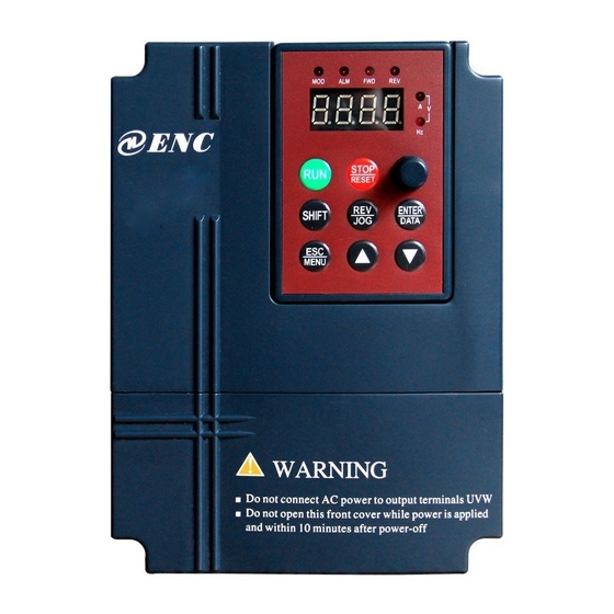
www.enc.net.cn/en Tel/Fax:86-755-26984485/26985120 2 Type and specification of the inverter 2.5 Appearance and parts name explanation LED display digital LED display digital potentiometer Upper cover plate potentiometer keypad keypad connection terminal Control cable nameplate nameplate inlet bottom fitting hole ventilation hole Control cable inlet Power supply input end Power supply input end,…
-
Page 14
www.enc.net.cn/en Tel/Fax:86-755-26984485/26985120 2 Type and specification of the inverter Table 2-2 EDS1000-2S0004~EDS1000-4T0750P mounting size Fixing Inverter type apertu Fig. G.W. (mm) (mm) (mm) (mm) (mm) (mm) (G: general; P: special) (kg) (mm) EDS1000/1300-2S0004 EDS1000/1300-2S0007 EDS1000/1300-2S0015 EDS1000/1300-2S0022 170 123.2 135.5 Fig a EDS1000/EDS1100/1300-4T0007G/0015P EDS1000/EDS1100/1300-4T0015G/0022P EDS1000/1100/1300-4T0022G/0037P… -
Page 15: Product Technic Index And Spec
www.enc.net.cn/en Tel/Fax:86-755-26984485/26985120 2 Type and specification of the inverter 2.7 Outer size of keypad and its fixing box (unit: mm) Fig.2-5 EN-KB5 outer size Fig.2-5 EN-KB5 hole size Fig.2-7 EN-KB6 outer size Fig.2-8 EN-KB6 hole size 2.8 Product technic index and spec Item Item description 3 phase 690V grade, 3 phase 690V ,50Hz/60Hz;…
-
Page 16
www.enc.net.cn/en Tel/Fax:86-755-26984485/26985120 2 Type and specification of the inverter G type: 150% of rating current for1 minute,200% Over loading capacity of rating current for 0.5 second; P type: 120% of rating current for 1 minute; Speed sensorless slip vector control, Control mode open loop V/F control Speed regulation range… -
Page 17
www.enc.net.cn/en Tel/Fax:86-755-26984485/26985120 2 Type and specification of the inverter Impulse square wave signal output of 0~20KHz, pulse output channel can realize output of physical parameter such as setting frequency, output frequency etc. 2 channel of analog signal output,thereinto AO1 channel can be 4~20mA or 0~10V and AO2 Analog output channel channel is 0~10V;… -
Page 18: Installation And Wiring
www.enc.net.cn/en Tel/Fax:86-755-26984485/26985120 3 Installation and wiring 3 Installation and wiring 3.1 Installation ambient 3.1.1 Demand for installation ambient (1) Installed in drafty indoor place, ambient temperature within -10ºC~40ºC, need external compulsory heat sink or reduce the volume if temperature exceeds 40ºC.
-
Page 19: Parts Disassembly And Installation
www.enc.net.cn/en Tel/Fax:86-755-26984485/26985120 3 Installation and wiring Leading divider Fig. 3-2 mounting of multiple inverters 3.2 Parts disassembly and installation 3.2.1 Key board disassembly and installation Mounting claw (1) Disassembly Let the forefinger press finger inlet on the keypad,depress fixing flexible plate on the top lightly, draw it outward, then Hook Mounting claw…
-
Page 20: Wiring Notice Points
www.enc.net.cn/en Tel/Fax:86-755-26984485/26985120 3 Installation and wiring (1) Disassembly First take off 2 screws at sides of the cover and move it a bit outward horizontally, then tilt it at 15 degree and draw it outward at direction shown in right figure, now you can take the cover off. (2) Assembly First put down the cover in parallel with unit body and make it just locked at 2 sides of the inverter, secondly force it ahead and make fixing part on its top…
-
Page 21: Main Loop Terminal Wiring
www.enc.net.cn/en Tel/Fax:86-755-26984485/26985120 3 Installation and wiring (1) Before wiring, assure power supply is cut off completely for 10 minutes and all LED indicator light extinguished. (2) Before internal wiring, confirm that DC volt. Between main loop end P+ and P- fall down to below DC36V.
-
Page 22
www.enc.net.cn/en Tel/Fax:86-755-26984485/26985120 3 Installation and wiring (5) Input side EMI filter Can use EMI filter to inhibit high-frequency conduction disturbance and emission Isolation switch disturbance from inverter power supply wire. Breaker or fuse (6) Output side EMI filter Can use EMI filter to inhibit AC input reactor(in option) emission disturbance noise and wire leakage current from output… -
Page 23: Main Loop Terminal Wiring
www.enc.net.cn/en Tel/Fax:86-755-26984485/26985120 3 Installation and wiring 3.4.2 Main loop terminal wiring For main loop input output terminal, see table 3-1. Table 3-1 main loop input output terminal description Adapted type Main loop terminal End name Function description Zero wire Live wire EDS1000-2S0004 DC volt.
-
Page 24
www.enc.net.cn/en Tel/Fax:86-755-26984485/26985120 3 Installation and wiring R, S, T 3 phase AC 380V input terminal EDS1000-4T0185G~ DC volt. positive end EDS1000-4T0550G Reserved terminal for S T P P+ P- U V W E exterior DC reactor EDS1000-4T0220P~ DC volt. negative end EDS1000-4T0750P U, V, W 3 phase AC output terminal… -
Page 25: Basic Running Wiring Diagram
www.enc.net.cn/en Tel/Fax:86-755-26984485/26985120 3 Installation and wiring Basic running wiring diagram Adapted type: EDS1000-2S0004~2S0037 EDS1000-4T0007~4T0015G EDS1000-4T0022G~EDS1000-4T0750P Braking unit Braking resistance (external,fitting part) (external,fitting part) breaker 3 phase R(L1 220V AC) 380V S(L2 220V AC) 50/60Hz Forward run/stop EDS1000 Reverse run/stop DC amperometer Multi-function 1 4-20mA current signal Multi-function 2…
-
Page 26: Control Loop Collocation And Wiring
www.enc.net.cn/en Tel/Fax:86-755-26984485/26985120 3 installation and wiring 3.6 Control loop collocation and wiring 3.6.1 Location&function of terminal and slide switch: For location of terminal and slide switch on the CPU board, please see Fig.3-10. Function description of terminal provided for the user, please see Table 3-2, function and setup description of slide switch, please see Table 3-3,…
-
Page 27
www.enc.net.cn/en Tel/Fax:86-755-26984485/26985120 3 installation and wiring Table 3-3 function description of slide switch provided for user Factory Symbol Function Setting default : 0~5V voltage signal; YCI: 5V/10V voltage 0~5V input mode selection : 0~10V voltage signal : 0~10V voltage signal; VCI: 5V/10V voltage 0~10V input mode selection… -
Page 28
www.enc.net.cn/en Tel/Fax:86-755-26984485/26985120 3 installation and wiring Input impedance of X7, Multi-function input 4 X7, X8 can be set as X8 input channel: H-speed impulse input port, R=2KΩ for detailed see Chapter 6 Multi-function input 5 Max. output Freq.: Section 6.6 terminal 20KHz Multi-function input 6 function parameter(F5… -
Page 29
www.enc.net.cn/en Tel/Fax:86-755-26984485/26985120 3 installation and wiring optocoupler isolation Open circuit collector output output terminal 1 Used for multi-function Work voltage range: switch output terminal, for Open circuit collector 15~30V detailed see Chapter 6 output terminal 2 Max. output current: Section 6.6 terminal 50mA function parameter (F5 Open circuit collector… -
Page 30: Analog Input Output Terminal Wiring
www.enc.net.cn/en Tel/Fax:86-755-26984485/26985120 3 installation and wiring Table 3-6 CPU board JP1 terminal function Item symbol name Function description Spec TB-TC: always-closed, TA-TC: always-open Relay Inverter Normal: TB-TC closed, TA-TC open Contact capacity: output malfunction Malfunction: TB-TC open, TA-TC AC250V/2A (COSΦ=1) terminal output relay closed…
-
Page 31
www.enc.net.cn/en Tel/Fax:86-755-26984485/26985120 3 installation and wiring (3) YCI terminal accepts analog voltage signal input,wiring mode as follows: YCI current input EDS1000 +10V 0~+10 0~5V Or 0~+5V YCI volt. ― Shielded wire close end grounded 0~10V Fig.3-13 YCI terminal wiring diagram Explanation: relation between YCI input voltage and set frequency is as following figure: 1>… -
Page 32: Communication Terminal Wiring
www.enc.net.cn/en Tel/Fax:86-755-26984485/26985120 3 installation and wiring Analog current output Analog meter 0~10V Analog voltage output 4~20mA Fig.3-14 analog output terminal wiring (1) When inputing anglog signal,can connect filter capacitor or common module inductance between VCI and GND or between CCI and GND or between YCI and GND.
-
Page 33
www.enc.net.cn/en Tel/Fax:86-755-26984485/26985120 3 installation and wiring (3) Connection between inverter RS485 interface and upper machine(with RS232 interface): RS232/RS485 converter Shielded Signal Pin no. cable Terminal explain Name shell 5Vpower positive Sending data line Receivingdata line 5VPower ground Terminal explain Name Name Terminal explain Signal negative end… -
Page 34: Installation Guide For Anti-Jamming
www.enc.net.cn/en Tel/Fax:86-755-26984485/26985120 3 installation and wiring 3.7 Installation guide for anti-jamming Main circuit of the inverter is composed of high-power semiconductor switch gear,so some electromagnetic noise will arise during work,to reduce or stop disturbance to environment,show you assembling method of inverter disturbance suppressing from many aspects such as disturbance suppressing, spot wiring, system grounding, leak current, usage of power supply filter etc.
-
Page 35
www.enc.net.cn/en Tel/Fax:86-755-26984485/26985120 3 installation and wiring (2) Noise spread road ⑧ ② ② ⑥ ⑤ ③ power supply inverter Wireless set meter ④ ⑦ sensor ⑤ motor ① Fig.3-19 noise disturbance spread road sketch (3) basic countermeasure for suppressing disturbance Table 3-7 disturbance suppressing countermeasure table Noise spread… -
Page 36: And The Countermeasure
www.enc.net.cn/en Tel/Fax:86-755-26984485/26985120 3 installation and wiring To prevent parallel or bundled power and weak conducting wire;should keep away from inverter mounted device to the best and its wiring should keep away from power wire of the inverter such as R, S, T, U, V, W etc.. Should pay attention to relative ⑥⑦⑧…
-
Page 37
www.enc.net.cn/en Tel/Fax:86-755-26984485/26985120 3 installation and wiring these electromagnetic on-off electronic device would bring lots of noise during work, so you should pay full attention to when installing them beside the inverter or in the same control chamber with the inverter and must install surge absorbing device as shown in Fig. -
Page 38: Run And Operation Explanation For Inverter
www.enc.net.cn/en Tel/Fax:86-755-26984485/26985120 4 Run and operation explanation for inverter 4 Run and operation explanation for inverter 4.1 Run of inverter 4.1.1 Running order channels There are 3 kinds of order channel for controlling run action of the inverter such as run, stop, jog etc.: 0: keypad Control by key on keypad(factory default).
-
Page 39: Run Mode
www.enc.net.cn/en Tel/Fax:86-755-26984485/26985120 4 Run and operation explanation for inverter 4.1.4 Run mode EDS1000 inverter have 6 kinds of run mode,following is in turn according to their priority: jog run→closed-loop run→PLC run→multisection speed run→ swing frequency run→common run. Shown as Fig.4-1. electrification waiting state…
-
Page 40
www.enc.net.cn/en Tel/Fax:86-755-26984485/26985120 4 Run and operation explanation for inverter The inverter will come into closed-loop run mode when closed –loop run control effective parameter is set(F3.00=1). Namely carry on PID adjustment to specified value and feedback value(proportion integral differential calculation, see F3 group function code) and PID adjustor output is inverter output frequency. -
Page 41: Operation And Use Of Key Board
www.enc.net.cn/en Tel/Fax:86-755-26984485/26985120 4 Run and operation explanation for inverter 4.2 Operation and use of key board 4.2.1 Keypad layout Keypad is main unit for receiving command, displaying parameter. Outer dimension of EN-KB6 is as Fig.4-2: Failure alarm indicator light Forward run indicator light Reverse run indicator light Mode indicator light Current unit(A)
-
Page 42: Led And Indicator Light
www.enc.net.cn/en Tel/Fax:86-755-26984485/26985120 4 Run and operation explanation for inverter Analog Be used to set frequency; when F0.00=0 value set by analog potentiometer potentiometer is frequency provision To increase data or function code (to press it continuously can Increasing button improve increasing speed) To decrease data or function code (to press it continuously can Decreasing button improve decreasing speed)
-
Page 43
www.enc.net.cn/en Tel/Fax:86-755-26984485/26985120 4 Run and operation explanation for inverter supervision parameter in function parameter schedule graph of chapter 5). (2) run parameter display status The inverter enters into run status when receiving effective run command and normally parameter F3.28 decide which status supervision parameter to be displayed on the keypad. -
Page 44: Method For Operating Keypad
www.enc.net.cn/en Tel/Fax:86-755-26984485/26985120 4 Run and operation explanation for inverter (4) function code editing status Under waiting, run or failure alarm status,press key,can enter into MENU editing status(If user password is set,can enter into editing status after inputting the password,see also FF.00 description and Fig.4-10),and editing status is displayed according to three classes menu mode,as shown in Fig.
-
Page 45
www.enc.net.cn/en Tel/Fax:86-755-26984485/26985120 4 Run and operation explanation for inverter LED displayed 50.00 C-01 Para. value C-02 Para. value content Set frequency Output frequency Output current Key-press SHIFT SHIFT operation order parameter C-14 parameter C-03 Output voltage Pulse input SHIFT SHIFT SHIFT ∫…∫… -
Page 46
www.enc.net.cn/en Tel/Fax:86-755-26984485/26985120 4 Run and operation explanation for inverter 3> Parameter protected. All the function code can’t be modified when function code F2.13=1 or 2,in order to avoid wrong operation. Need to set the function code F2.13 to 0 if you want to edit function code parameter. (3) Specified frequency adjustment for common run Take example modifying specified frequency from 50.00Hz to 40.00Hz at F0.00=0 during running for explanation. -
Page 47
www.enc.net.cn/en Tel/Fax:86-755-26984485/26985120 4 Run and operation explanation for inverter (6) See about failure parameter under failure status: LED displayed Fd.06 50:00 Fd.07 45:00 Fd.08 E001 content Failure output freq. Key-press Failure current Failure set freq. SHIFT SHIFT SHIFT operation order 1500 Fd.14 1111… -
Page 48: Inverter Electrification
www.enc.net.cn/en Tel/Fax:86-755-26984485/26985120 4 Run and operation explanation for inverter 4.3 Inverter electrification 4.3.1 Check before electrification Please carry on wiring based on operation requirement provided in “inverter wiring” of this Service manual. start 4.3.2 First electrification Close input side AC power wiring based on 3.5 section supply switch after correct wiring and power supply confirmed,…
-
Page 49: Function Parameter Schedule Graph
www.enc.net.cn/en Tel/Fax:86-755-26984485/26985120 5 Function parameter schedule graph 5 Function parameter schedule graph 5.1 Symbol description × —- parameter can’t be changed in process of running ○ —- parameter can be changed in process of running * —- read-only parameter, unmodifiable 5.2 Function parameter schedule graph F0-Basic run function parameter group Function…
-
Page 50
www.enc.net.cn/en Tel/Fax:86-755-26984485/26985120 5 Function parameter schedule graph × F0.11 Lower limit freq. 0.00-Upper limit freq. 0.01Hz 0.00Hz 0: run at lower limit freq. Lower limit freq. × F0.12 1: stop by slow down run mode 2: free stop Torque boost 0: manual boost ○… -
Page 51
www.enc.net.cn/en Tel/Fax:86-755-26984485/26985120 5 Function parameter schedule graph F2-Auxiliary run function parameter group Function Min. Factory Modifi Name Set range code unit default -cation Analog filter time ○ F2.00 0.00-30.00s 0.01s 0.20s constant Forward reverse ○ F2.01 run dead-section 0.0-3600.0s 0.1s 0.1s time Automatic energy… -
Page 52
www.enc.net.cn/en Tel/Fax:86-755-26984485/26985120 5 Function parameter schedule graph 0000-1111 first bit: running time 0: not display 1: display second bit: accumulative time 0: not display LED display 1: display ○ F2.11 0000 control 1 third bit: input terminal status 0: not display 1: display kilobit(fourth bit): output terminal status… -
Page 53
www.enc.net.cn/en Tel/Fax:86-755-26984485/26985120 5 Function parameter schedule graph LED second bit: data format 0: 1-8-1format, no checkout 1: 1-8-1 format, even checkout 2: 1-8-1 format, odd checkout 0-127,127 is broadcast address. The inverter only × F2.15 Local address receive but not send when it is set to be 127, 0 is address for main device. -
Page 54
www.enc.net.cn/en Tel/Fax:86-755-26984485/26985120 5 Function parameter schedule graph Jumping freq. 3 × F2.50 0.00-30.00Hz 0.01Hz 0.00Hz range ○ F2.51 Sett run time 0-65535 hours Run time F2.52 0-65535 hours accumulation 0: a ASCII frame of 14 byte or 18 byte 1: a hex frame of 8 byte or 10 byte, original response not changed RS485/232 2: a hex frame of 8 byte or 10 byte, 12 command has… -
Page 55
www.enc.net.cn/en Tel/Fax:86-755-26984485/26985120 5 Function parameter schedule graph ○ F3.11 Sampling cycle T 0.01-1.00s 0.01s 0.10s ○ F3.12 Deviation limit 0.0-20.0(%)percentage relative to 10.00V 0.1(%) 2.0(%) Integral separation ○ F3.13 PID adjusting 0.0-100.0% 0.1% 100.0% threshold Closed-lop preset ○ F3.14 0-upper limit frequency 0.01Hz 00.00 frequency… -
Page 56
www.enc.net.cn/en Tel/Fax:86-755-26984485/26985120 5 Function parameter schedule graph 13: analog input YCI 14: exterior pulse inputs YCI run-in delay ○ F3.29 0.0-999.9s 10.0 time 0: inverter running(RUN) 1: frequency arriving signal(FAR) 2: frequency level detect signal (FDT1) 3: reserved 4: overload warning alarm signal (OL) 5: output frequency reach high limit(FHL) 6: output frequency reach low limit(FLL) 7: inverter under voltage blockage stop (LU) -
Page 57
www.enc.net.cn/en Tel/Fax:86-755-26984485/26985120 5 Function parameter schedule graph 0: Acce/Dece time 1 1: Acce/Dece time 2 2: Acce/Dece time 3 3: Acce/Dece time 4 4: Acce/Dece time 5 5: Acce/Dece time 6 6: Acce/Dece time 7 ○ F4.02 Section 1 run time 0-6000.0 10.0 ○… -
Page 58
www.enc.net.cn/en Tel/Fax:86-755-26984485/26985120 5 Function parameter schedule graph 32: swing frequency jump-in 33: external interruption input 34: interior counter clearing end 35: interior counter triggering end 36: interior timer clearing end 37: interior timer triggering end 38: pulse frequency input(only effective forX7,X8) 39: reserved 40: reserved 41: reserved… -
Page 59
www.enc.net.cn/en Tel/Fax:86-755-26984485/26985120 5 Function parameter schedule graph 24: reserved Open circuit collector output × F5.11 Same as above terminal OC2 output setting Open circuit collector output × F5.12 Same as above terminal OC3 output setting Open circuit collector output × F5.13 Same as above terminal OC4… -
Page 60
www.enc.net.cn/en Tel/Fax:86-755-26984485/26985120 5 Function parameter schedule graph F6-Traverse special function parameter group Function Min. Factory Modifi Name Set range code unit default -cation Traverse function 0: traverse function not used × F6.00 selection 1: traverse function used LED first bit: jump-in mode 0: automatic jump-in mode 1: terminal manual jump-in mode LED second bit:… -
Page 61
www.enc.net.cn/en Tel/Fax:86-755-26984485/26985120 5 Function parameter schedule graph PULSE max. provision corresponding ○ F7.17 0.00-high limit frequency 0.01 Hz 50.00 Hz freq. F8-Motor and vector control parameter group Function Min. Factory Modifi Name Set range code unit default -cation 0: V/F control ×… -
Page 62
www.enc.net.cn/en Tel/Fax:86-755-26984485/26985120 5 Function parameter schedule graph Overload warning ○ F9.05 20-200(%) 1(%) 130(%) alarm checkout level Overload warning ○ F9.06 0.0-20.0s 0.1s 5.0s alarmDelay time Overvoltage stall 0: ban × F9.07 selection 1: allow Overvoltage stall ○ F9.08 120-150(%) 1(%) 130(%) point… -
Page 63
www.enc.net.cn/en Tel/Fax:86-755-26984485/26985120 5 Function parameter schedule graph C-Supervision function parameter group Function Min. Factory Modifi Name Description code unit default -cation C-00 Set frequency Current set frequency 0.01HZ C-01 Output freq. Current output freq. 0.01HZ C-02 Output current Virtual value of current output current 0.1A C-03 Output voltage… -
Page 64: Detailed Function Description
www.enc.net.cn/en Tel/Fax:86-755-26984485/26985120 Detailed function description Detailed function description Listed column content for parameter function code description in this chapter is as follows: Code Name Set range or description Factory default 6.1 Basic run function parameter group: F0 F0.00 Frequency input channel selection range: 0~11 0: keypad analog potentiometer setting.
-
Page 65
www.enc.net.cn/en Tel/Fax:86-755-26984485/26985120 Detailed function description 11: terminal PWM pulse width set frequency. Relation between frequency and input information is determined by function code F7.00~F7.17 when frequency input channel is 4, 5, 6, 7,please see Section 6.8. note F0.01 Freq. digit setting range: low limit~high limit 50.00Hz F0.01 parameter is original set frequency of the inverter when frequency setting… -
Page 66
www.enc.net.cn/en Tel/Fax:86-755-26984485/26985120 Detailed function description F0.04 Acce/Dece mode selection range: 0, 1 0: linear Acce/Dece mode. Output frequency increases or decreases according to constant slope, just as shown in Fig.6-1. 1: S curve Acce/Dece mode. Output frequency increases or decreases according to S curve, just as shown in Fig.6-2. -
Page 67
Fig.6-3 Acce/Dece time definition (1) In EDS1000 series inverter 7 kinds of Acce/Dece time are defined in total, here we only define Acce/Dece time 1,Acc/Dec time 2~7 are defined in F2.18~F2.29, please refer to Section 6.3. -
Page 68
www.enc.net.cn/en Tel/Fax:86-755-26984485/26985120 Detailed function description saturation when lightly loaded. 1: automatic torque boost. Torque boost voltage varies as stator current of the motor changes,bigger stator current corresponds to bigger boost voltage. inverter output current F0.14 ×motor rated volt.× Boost volt.= 2×inverter rated current F0.14 Torque boost… -
Page 69: Start, Stop, Braking Function Parameter Group:f1
www.enc.net.cn/en Tel/Fax:86-755-26984485/26985120 Detailed function description characteristic to reach better energy save result while the inverter is driving degressive torque load such as blower and water pump etc.. If F0.15=4, you can set V/F curve yourself by setting F2.37-F2.44 parameters. As shown in Fig.6-5b, by setting three inflexion point (V1,F1), (V2,F2), (V3,F3), you can define V/F curve arbitrarily to apply to special load.
-
Page 70
www.enc.net.cn/en Tel/Fax:86-755-26984485/26985120 Detailed function description F1.01 Starting frequency range: 0.0-10.00Hz 0.00Hz F1.02 Starting freq. duration time range: 0.0-20.0S 0.0S Starting frequency means initial frequency at which the inverter start up,as fs shown in Fig.6-6;Starting freq. holding time means consecutive run time during which the inverter run at starting frequency,as t shown in Fig.6-6. -
Page 71: Auxiliary Run Function Parameter Group: F2
www.enc.net.cn/en Tel/Fax:86-755-26984485/26985120 Detailed function description F1.05 Stop mode Range: 0, 1, 2 0: Dece stop. The inverter reduces output frequency gradually according to set Dece time upon receival of stop command and stops running after frequency is reduced to 0. 1: free stop.
-
Page 72
www.enc.net.cn/en Tel/Fax:86-755-26984485/26985120 Detailed function description To reach better energy save result, the inverter would detect load current to get the purpose of automatic energy save. 0: no action 1: action Empty or lightly loaded motor can get the purpose of energy save by detecting load current to adjust output voltage properly. -
Page 73
www.enc.net.cn/en Tel/Fax:86-755-26984485/26985120 Detailed function description Carrier frequency mainly affects motor noise and heat consumption during running. Relation between carrier frequency and motor noise, current leakage, disturbance is as follows: Carrier frequency increase(↑),motor noise decrease(↓),motor current leakage increase(↑),disturbance to environment increase(↑); Carrier frequency decrease (↓),motor noise increase (↑),motor current leakage decrease (↓),disturbance to environment decrease (↓)。… -
Page 74
www.enc.net.cn/en Tel/Fax:86-755-26984485/26985120 Detailed function description Jog accelerating time means time during which the inverter accelerate from 0Hz to high limit frequency,Jog Dec time means time during which the inverter decelerate from high limit frequency to 0Hz. Jog decelerating time freq. freq. -
Page 75
www.enc.net.cn/en Tel/Fax:86-755-26984485/26985120 Detailed function description 13: VCI,CCI any nonzero value effective,VCI preferred 14: reserved 15: RS485+CCI 16: RS485-CCI 17: RS485+VCI 18: RS485-VCI 19: RS485+keypad analog potentiometer 20: RS485- keypad analog potentiometer 21: VCI+ keypad analog potentiometer 22: VCI- keypad analog potentiometer 23: CCI+ keypad analog potentiometer 24: CCI- keypad analog potentiometer 25: reserved… -
Page 76
www.enc.net.cn/en Tel/Fax:86-755-26984485/26985120 Detailed function description F2.12 make use of 4 bit of the parameter to set if C-11—C-14 is displayed in parameter, thereinto 0 indicates not displayed, 1 indicates displayed. Set parameter of 4 bit is as following figure: C-11: analog input VCI C-12: analog input YCI C-13: analog input CCI C-14: outer pulse input… -
Page 77
www.enc.net.cn/en Tel/Fax:86-755-26984485/26985120 Detailed function description range: LED 1 bit: 0~5 F2.14 communication configuration LED 2 bit: 0, 1, 2 F2.14 make use of 1 bit, 2 bit to set baud rate and data format of serial communication,thereinto LED 1 bit represents communication baud rate, set value as follows: 0: 1200BPS 1: 2400BPS… -
Page 78
www.enc.net.cn/en Tel/Fax:86-755-26984485/26985120 Detailed function description F2.18 Acce time 2 range: 0.1-6000.0 20.0 F2.19 Dece time 2 range: 0.1-6000.0 20.0 F2.20 Acce time 3 range: 0.1-6000.0 20.0 F2.21 Dece time 3 range: 0.1-6000.0 20.0 F2.22 Acce time 4 range: 0.1-6000.0 20.0 F2.23 Dece time 4 range: 0.1-6000.0… -
Page 79
www.enc.net.cn/en Tel/Fax:86-755-26984485/26985120 Detailed function description 0.00-F2.39 F2.37 VF frequency value 0 10.00Hz 0.00-F2.40 F2.38 VF voltage value 0 20.00% F2.37-F2.41 F2.39 VF frequency value 1 20.00Hz F2.38-F2.42 F2.40 VF voltage value 1 40.00% F2.39-F2.43 F2.41 VF frequency value 2 25.00Hz F2.40-F2.44 F2.42 VF voltage value 2… -
Page 80: Closed-Loop Run Function Parameter Group: F3
www.enc.net.cn/en Tel/Fax:86-755-26984485/26985120 Detailed function description F2.51 Set run time range: 0-65535h F2.52 Run time accumulation range: 0-65535h After run accumulative time reach set run time (F2.51),the inverter will output indicator signal,please refer to F5.10~F5.13 function introduction. F2.52 denotes accumulative run time of the inverter from leaving factory tonow. RS485/232 communication F2.53 range: 0-4…
-
Page 81
www.enc.net.cn/en Tel/Fax:86-755-26984485/26985120 Detailed function description EDS1000 built-in PID adjustor make up of control system and its work principle chart is as follows: proportion gain (F3.08) specified value error limit adjusting integral Closed-loop closed-loop (F3.12) gain (F3.04,F3.06) output specified value (F3.09) differenti- al gain (F3.10) -
Page 82
www.enc.net.cn/en Tel/Fax:86-755-26984485/26985120 Detailed function description cycle, error limit (F3.08~F3.12) F3.00 Closed-loop run control selection range: 0, 1, 2 0: closed-loop run control ineffective 1: PID closed-loop run control effective 2: constant pressure water supply PID control effective This parameter is mainly used for implementing one-driving-two water supply function. -
Page 83
www.enc.net.cn/en Tel/Fax:86-755-26984485/26985120 Detailed function description range: 0.0-max. F3.04 min. specified value 0.0(%) specified value corresponding feedback F3.05 range: 0.0-100.0(%) 0.0(%) value of min. specified value range: min. specified F3.06 max. specified value value 100.0(%) value -100.0(%) corresponding feedback F3.07 range: 0.0%-100.0(%) 100.0(%) value of max. -
Page 84
www.enc.net.cn/en Tel/Fax:86-755-26984485/26985120 Detailed function description F3.12 Deviation limit range: 0.0-20.0(%) 2.0(%) For Max. offset of closed-loop specified value,as shown in Fig.6-17,PID adjustor stops adjusting when feedback value is within this range. To utilize this function reasonably redound to harmonizing the conflict between system output precision and stabilization. -
Page 85
www.enc.net.cn/en Tel/Fax:86-755-26984485/26985120 Detailed function description the scope of F3.12 (deviation limit), and the inverter operating frequency is under the F3.16 (sleep frequency), after the F3.18 (sleep delay time), the inverter will enter a sleep state, operating frequency will drop to 0.00HZ in order to save energy conservation and protect motor. -
Page 86
www.enc.net.cn/en Tel/Fax:86-755-26984485/26985120 Detailed function description This parameter defines the action delay time of magnetic control conductor when it’s from power source to variable frequency or from variable frequency to power source. range: 0000-9999 F3.25 Automatic switchover interval 0000 By setting this parameter, can achieve the function of rust-proof die of the motor, the inverter can delay time by it and then automatically smart switch run pumps and static pump. -
Page 87: Simple Plc Function Parameter Group:f4
PLC circle finishing indication Fig.6-19 simple PLC run EDS1000 series inverter simple PLC run function can provide 7 kinds of multi-speed operation mode, take the fowling 7speed for example Figure 6 -20 , a1~ a5, d1~d5Is the speed up time and the deceleration time of the stage, they are…
-
Page 88
www.enc.net.cn/en Tel/Fax:86-755-26984485/26985120 Detailed function description setted by the acceleration time parameters F 0.08,F0.09and F2.18~F2.29, a total of seven kinds of parameters, the run frequency and run time of f1~ f7, T1~ T7 are setted by function code F4.01~f4.14. Simple PLC run RUN command Fig.6-20 stop after PLC single circle PLC step finishing and circle finishing indication can be realized by outputting… -
Page 89
www.enc.net.cn/en Tel/Fax:86-755-26984485/26985120 Detailed function description RUN command STOP command Fig.6-21 holding mode after PLC single circle PLC run T1 T2 T3 T4 T5 T6 T7 T1 T2 T3 T4 T5 T6 T7 T1 Second circle First circle RUN command STOP Fig.6-22 PLC consecutive circle mode 3: consecutive circulation. -
Page 90
www.enc.net.cn/en Tel/Fax:86-755-26984485/26985120 Detailed function description Interruption signal output freq.Hz Time t Step 1 Step 2 Step 2 residual time Used time : step 1 accelerating time : step 2 accelerating time : step 3 accelerating time : step 2 decelerating time : step 1 frequency : step 2 frequency : step 3 frequency… -
Page 91: Terminal Correlative Function Parameter Group: F5
www.enc.net.cn/en Tel/Fax:86-755-26984485/26985120 Detailed function description F4.01~F4.14 utilize LED 1st bit, 2nd bit, 3rd bit to separately define frequency setting,direction and accelerating decelerating time of PLC Run, see following for detail: LED1 bit: frequency setting 0: multi-step frequency i i=1~7 is defined by F2.30~F2.44. 1: frequency is determined by function code F0.00 LED 2 bit: run direction selection…
-
Page 92
www.enc.net.cn/en Tel/Fax:86-755-26984485/26985120 Detailed function description Table 6-2 multifunction input function selection table item corresponding function item corresponding function Leave control terminal unused Multi-step speed control terminal 1 Multi-step speed control terminal 2 Multi-step speed control terminal 3 Multi-step speed control terminal 4 External forward run jog control External reverse run jog control Acce/Dece time selecting terminal 1… -
Page 93
www.enc.net.cn/en Tel/Fax:86-755-26984485/26985120 Detailed function description Table 6-3 multi-step speed run selection table Frequency setting Common run frequency Multi-step frequency 1 Multi-step frequency 2 Multi-step frequency 3 Multi-step frequency 4 Multi-step frequency 5 Multi-step frequency 6 Multi-step frequency 7 Above multi-step frequency can be used in multi-step speed run and simple PLC run, please see below an example of multi-step speed run: We now define control terminal X1, X2, X3, separately as follows: After set F5.00=1, F5.01=2, F5.03=3, X1, X2, X3, are used for realizing… -
Page 94
www.enc.net.cn/en Tel/Fax:86-755-26984485/26985120 Detailed function description 3 phase breaker 3 phase AC power supply Fig.6-25 Fig.6-26 multi-step speed run exterior device failure always-open input 5~6: external jog run control input JOGF/JOGR. When run command channel is set to terminal run command channel F0.02=1,JOGF is jog forward run ,… -
Page 95
www.enc.net.cn/en Tel/Fax:86-755-26984485/26985120 Detailed function description RESET function of key on the operation panel. 12: free stop input. This function is same as free stop during running defined in F1.05,but it’s realized by control terminal to be convenient for long-distance control. 13: exterior stop command. -
Page 96
www.enc.net.cn/en Tel/Fax:86-755-26984485/26985120 Detailed function description 22: simple PLC pause command. Implement pause control to PLC process during running,run at zero frequency when this terminal is effective,not time for PLC run;after ineffective implement automatic speed tracking start and continue PLC run. For application method please refer to function description of F4.00~F4.14. -
Page 97
www.enc.net.cn/en Tel/Fax:86-755-26984485/26985120 Detailed function description Table 6-6 Run command channel logic mode Run command Run command Run command channel selection channel selection channel selection Run command channel terminal 3 terminal 2 terminal 1 hold run command channel keypad run command channel end run command channel (keypad STOP command… -
Page 98
www.enc.net.cn/en Tel/Fax:86-755-26984485/26985120 Detailed function description 39: reserved 40: reserved 41: reserved 42: reserved F5.08 FWD/REV run mode selection range: 0-3 This parameter defines 4 kinds of exterior terminal control mode for inverter running. 0: 2-wire control mode 1 run command EDS1000 stop reverse run… -
Page 99
www.enc.net.cn/en Tel/Fax:86-755-26984485/26985120 Detailed function description Xi is multifunction input terminal of X1~X8, here should define its corresponding terminal function as No. 19 “3-wire run control” function. 3: 3-wire control mode 2 SB1: stop button SB2: run button EDS1000 run direction selection Forward run Reverse run… -
Page 100
www.enc.net.cn/en Tel/Fax:86-755-26984485/26985120 Detailed function description Overload warning signal(OL) Output Freq. reach high limit(FHL) Inverter stop for under voltage Output Freq. reach low limit(FLL) blockage (LU) Stop for exterior failure(EXT) Inverter zero rotate speed running PLC running Simple PLC segment run finished PLC finish one cycle run Reserved Inverter ready to run(RDY) -
Page 101
www.enc.net.cn/en Tel/Fax:86-755-26984485/26985120 Detailed function description frequency but in run status, output indicator signal. 10: PLC running 11: Simple PLC segment running finished. After simple PLC current segmentrun is finished, output indicator signal(single pulse signal, width 500ms). 12: PLC finish one cycle run 13: reserved 14: Inverter ready to run(RDY). -
Page 102
www.enc.net.cn/en Tel/Fax:86-755-26984485/26985120 Detailed function description 24: Reserved F5.14 Freq. arriving(FAR)detect range range: 0.00-50.00Hz 5.00Hz This parameter is supplementary definition to No. 1 function in Table 6-7.As shown in Fig.6-32,when output frequency of the inverter is within high&low detect range of set frequency,output pulse signal. FDT1(freq. -
Page 103
www.enc.net.cn/en Tel/Fax:86-755-26984485/26985120 Detailed function description F5.21 Analog output(AO2)gain range: 0.10-2.00 1.00 F5.22 Analog output(AO2) offset range: 0.00-10.00V 0.00 Same as F5.18 and F5.19 function parameter description. This function makes real-time effect to analog output when it’s being modified. note F5.23 DO terminal output function selection range: 0~9 Same as F5.17 function parameter description. -
Page 104: Traverse Special Function Parameter Group: F6
www.enc.net.cn/en Tel/Fax:86-755-26984485/26985120 Detailed function description F5.27 Interior timing setting range: 0.1-6000.0s 60.0 This parameter is used to set timing time of interior timer of the inverter. The timer is activated by exterior triggering end(triggering end selected by F5.00~F5.07), the timer begins timing upon receiving exterior triggering signal, after it’s up to timing time one effective pulse signal of 0.5s will be outputted from relative OC end.
-
Page 105
www.enc.net.cn/en Tel/Fax:86-755-26984485/26985120 Detailed function description F6.04 Traverse cycle range: 0.1-999.9S 10.0S Whole time for a cycle including traverse rising, descending process. Triangle wave range: 0.0-98.0(%)(traverse F6.05 50.0(%) rising time cycle) Define runtime of traverse rising segment=F6.04×F6.05 (s),runtime of descending segment = F6.04 × (1-F6.05) (s). Please refer to description in Fig.6-35. -
Page 106: Frequency Provision Function Parameter Group: F7
www.enc.net.cn/en Tel/Fax:86-755-26984485/26985120 Detailed function description 6.8 Frequency provision function parameter group: F7 F7.00 VCI min. provision range: 0.00-F7.02 0.0V VCI min. provision range: 0.00-high limit F7.01 0.00Hz corresponding freq. frequency F7.02 VCI max. provision range: 0.00-10.00V 9.9V VCI max. provision range: 0.00-high limit F7.03 50.00Hz…
-
Page 107
www.enc.net.cn/en Tel/Fax:86-755-26984485/26985120 Detailed function description range: F7.14(PULSE min. F7.16 PULSE max. provision provision)-F7.13(max. 10.0K input pulse) PULSE max. provision range: 0.00-high limit F7.17 50.00Hz corresponding freq. frequency F2.00 sets the analog channel filtering time constant, to filter input signal, the more long filtering time is, the more great anti-jamming ability is, but response speed descend;… -
Page 108: Motor And Vector Control Parameter Group: F8
www.enc.net.cn/en Tel/Fax:86-755-26984485/26985120 Detailed function description See below relation curve of YCI and set frequency: fmax Amax Amin dead band fmin A:YCI provision Amin: min. provision fmin: corresponding freq. to min. provision Amax: max. provision fmax: corresponding freq. to max. provision See below relation curve of PULSE and set frequency: Set freq.
-
Page 109
www.enc.net.cn/en Tel/Fax:86-755-26984485/26985120 Detailed function description Depend on F8.01 Motor rated voltage range: 1-480V device type Depend on F8.02 Motor rated current range: 0.1-999.9A device type Depend on F8.03 Motor rated frequency range: 1.00-400.0Hz device type Depend on F8.04 Motor rated speed range: 1-9999r/min device type Depend on… -
Page 110: Protection Function Parameter Group:f9
www.enc.net.cn/en Tel/Fax:86-755-26984485/26985120 Detailed function description Motor stability coefficient range: 0—4 F8.15 Filter time displayed instead freq. range: 0~999 F8.16 If surge happens or the motor run unstably, you can eliminate surge by increasing F8.15. F8.17 Motor speed correction factor Range :0-9999% 100% This parameter check display error, have no effect on the actual value.
-
Page 111
www.enc.net.cn/en Tel/Fax:86-755-26984485/26985120 Detailed function description 0: no action. No motor overload protection characteristic(apply with caution),here the inverter have no overload protection for load motor; 1: inverter cut off output at once. The inverter cut off output and motor stop freely when overload, overheat take place. Motor overload protection F9.04 range: 20.0-120.0(%) -
Page 112
www.enc.net.cn/en Tel/Fax:86-755-26984485/26985120 Detailed function description 0: banned 1: allowed Actual descending rate of motor speed may be lower than that of output frequency due to effect from load inertia when the inverter is in decelerating run process, here the motor will feed electric energy back to inverter which will make DC bus-bar voltage of the inverter increase, overvoltage protection will takes place if not take steps. -
Page 113: Failure Record Function Parameter Group: Fd
www.enc.net.cn/en Tel/Fax:86-755-26984485/26985120 Detailed function description By automatic current limiting function the inverter can limit load current not to exceed automatic current limiting level set by F9.09 to avoid tripping out for failure caused by rushing current. This function is especially suitable for some biggish inertia or acutely changing load occasion.
-
Page 114: Password And Manufacturer Function Parameter Group: Ff
www.enc.net.cn/en Tel/Fax:86-755-26984485/26985120 Detailed function description Fd.06 Set freq. at previous failure range: 0-high limit Fd.07 Output freq. at previous failure range: 0-high limit Fd.08 Output current at previous failure range: 0-999.9A Fd.09 Output volt. at previous failure range: 0-999V Fd.10 DC bus-bar volt.
-
Page 115: Stop Assistant Function Parameter Group: Fa
www.enc.net.cn/en Tel/Fax:86-755-26984485/26985120 Detailed function description 6.13 Stop assistant function parameter group: FA FA.00 Auxiliary DC brake time Range:0.0-20.0s 0.0s FA.01 Auxiliary DC brake voltage Range:0-15(%) Auxiliary DC brake means when the inverter stop DC brake is finished give the second stage DC braking. Role in some special circumstances require rapid braking, and stop long time in the state of DC braking, but to prevent motor heat circumstances.
-
Page 116: Troubleshooting
www.enc.net.cn/en Tel/Fax:86-755-26984485/26985120 7 Troubleshooting 7 Troubleshooting 7.1 Failure and countermeasure Possible failure types in EDS1000 are shown in Table 7-1 and failure code is from E001 to E023. Some failure code is reserved for intelligent automatic diagnosis function which will be executed continuously in future. When failure takes place in the inverter, the user should check according to note of this table first and record failure phenomena detailedly.
-
Page 117
www.enc.net.cn/en Tel/Fax:86-755-26984485/26985120 7 Troubleshooting E008 Inverter Accel time is set to too short Prolong accelerating time overload Reduce DC injection braking DC injection braking is too big current,prolong braking time improper V/F curve Adjust V/F curve and torque boost Restart rotating motor Set speed checking restart function power source voltage is too low check power source voltage Load is too big… -
Page 118: Failure Record Lookup
www.enc.net.cn/en Tel/Fax:86-755-26984485/26985120 7 Troubleshooting Baud rate set improperly set Baud rate properly STOP press key to reset, RESET Serial port communication error E016 RS485 look for service communication Failure warning parameter set failure Modify F2.16, F2.17 improperly Check if upper device work and wiring Upper device doesn’t work is correct E017 reserved…
-
Page 119: Failure Reset
www.enc.net.cn/en Tel/Fax:86-755-26984485/26985120 7 Troubleshooting 7.3 Failure reset (1) Before reset you must find out reason of failure downright and eliminate it, otherwise may cause permanent damage to the inverter. (2) If can’t reset or failure takes place again after resetting, should look for reason and continuous resetting will damage the inverter.
-
Page 120: Maintenance
www.enc.net.cn/en Tel/Fax:86-755-26984485/26985120 8 Maintenance 8 Maintenance 8.1 Routine maintenance When you use ESD1000 series you must assemble and operate it according to demand listed in this《service manual》strictly. During run state, temperature, humidity, vibration and aging parts may affect it. To avoid this, it is recommended to perform routine inspections.
-
Page 121: Repair Guarantee
www.enc.net.cn/en Tel/Fax:86-755-26984485/26985120 8 Maintenance (2) filter electrolyte capacitance When frequent-changing load causes increasing pulsant current and aging electrolyte under high ambient temperature, the electrolyte capacitance may be damaged and here should replace it. 8.3 Repair guarantee (1) Within 18 months from purchasing date, if failure caused by inverter itself takes place under normal conservation and usage, we will provide free repair service.
-
Page 122: Fitting Parts
www.enc.net.cn/en Tel/Fax:86-755-26984485/26985120 9 Fitting parts 9 Fitting parts 9.1 Communication subassembly 9.1.1 Long-distance operation key board Maximum electric distance from local keypad to inverter is 2m. RS485 communication mode is adopted between inverter and long-distance keypad,only a four-core cable is needed between them and maximum electric distance can reach 1000m.They communicate with each other in main-auxiliary mode, namely take long-distance keypad as main device and inverter as auxiliary one.
-
Page 123: Examples
www.enc.net.cn/en Tel/Fax:86-755-26984485/26985120 10 Examples 10 Examples 10.1 Common speed regulation running 10.1.1 Basic wiring diagram 3 phase breaker motor EDS1000 failure waring light ENTER DATA cymometer Fig.10-1 10.1.2 Set following basic parameter: (1) set parameter F8.01-F8.06 according to rated value of the motor. (2) set F0.00 parameter to 0,…
-
Page 124: Terminal Control Running
www.enc.net.cn/en Tel/Fax:86-755-26984485/26985120 10 Examples 10.2 Terminal control running 10.2.1 Basic wiring diagram 3 phase breaker motor EDS1000 3 phase 380V 50/60Hz failure warning light forward run reverse run 10V/5V specified signal 10K ammeter Fig.10-2 10.2.2 Parameter setting (1) Set parameter F8.01-F8.06 according to rated value of the motor. (2) Set F0.00 parameter to 4~6 to choose VCI, CCI, YCI accordingly, can accept frequency set signal within 0~10V.
-
Page 125: Multi-Step Speed Control Running
www.enc.net.cn/en Tel/Fax:86-755-26984485/26985120 10 Examples 10.3 Multi-step speed control running 10.3.1 Parameter setting (1) Set parameter F8.01-F8.06 according to rated value of the motor. (2) Set F0.02 parameter to 1,to choose terminal run command channel. (3) F2.30-F2.44: multi-step speed frequency setting. (4) F5.00-F5.07 set multi-step speed terminal control function.
-
Page 126: Closed-Loop Control System
www.enc.net.cn/en Tel/Fax:86-755-26984485/26985120 10 Examples 10.3.3 Realized function (1) make use of external on-off quantum signal to control start/stop of the motor. (2) make use of external on-off quantum signal to make the motor run at set frequency. (3) bear free stop and reset function by utilizing external on-off quantum signal. (4) bear warning alarm and PLC run indication function.
-
Page 127: Consecutive Action Running
www.enc.net.cn/en Tel/Fax:86-755-26984485/26985120 10 Examples tomake constant voltage, constant temperature, constant current etc. available. (2) can control start/stop of the motor from long distance. (3) bear failure alarm and current indicator function. 10.4.4 Application field Applied in field where need stable system, pressure, flux such as blower pump, constant pressure water supply, air compressor, air conditioner, freezer cooling tower, music fountain, heat supply etc..
-
Page 128: Application To Constant Pressure Water Supply
www.enc.net.cn/en Tel/Fax:86-755-26984485/26985120 10 Examples passed to 2# inverter through serial communication. 10.5.4 Application field Applied in field such as conveyer belt, coiler, factory production line, food chemistry etc. 10.6 Application to constant pressure water supply 10.6.1 Summary for constant pressure water supply board This constant pressure water supply board (hearafter in 10.6 referenced as “the board”) is constant pressure water supply controller for multiple pumps, and it has to work with EDS1000 to control constant pressure water supply system for…
-
Page 129
www.enc.net.cn/en Tel/Fax:86-755-26984485/26985120 10 Examples ENC constant pressure water supply board COM Y Z1 Z2 A B +24V X1 X2 +24V Fig.10-7 connection between water supply controller and inverter Explanation for terminals: A, B terminals of constant pressure water supply board are for RS485 receving and sending, Z1 is over pressure signal output terminal when pump increased, Z2 is pressure falling signal output terminal when pump reduced, Y is fire fighting pump control signal input terminal, +24V, COM are respectively power supply input terminal and grounding terminal of the board. -
Page 130
www.enc.net.cn/en Tel/Fax:86-755-26984485/26985120 10 Examples frequency. Bypass run means that the motor is connected to power source directly. Variable frequency/ bypass switch means process from inverter drive to power source drive or from power source drive to inverter drive. (2) Operation mode a. -
Page 131
www.enc.net.cn/en Tel/Fax:86-755-26984485/26985120 10 Examples order to avoid water pressure fluctuation when pump adding or reducing. For detailed parameter setting information, please see below table. function name set range explanation code Set according to actual F0.08 Acce time 1 situation F0.09 Dece time 1 Same as above F0.10… -
Page 132
www.enc.net.cn/en Tel/Fax:86-755-26984485/26985120 10 Examples Input terminal X1 This parameter must be set to 33: F5.00 function selection external interruption input The output setting of output terminal This parameter is used when choose F5.10 of open collector OC1 inverter to supply water The output setting of output terminal F5.11 Same as above… -
Page 133
www.enc.net.cn/en Tel/Fax:86-755-26984485/26985120 10 Examples (2) Basic wiring diagram 3 phase breaker inverter M1-3 3 phase breaker 2 phase breaker Constant pressure M2-3 Water supply controller M3-3 M4-3 Fig.10-10 basic wiring diagram for constant pressure water supply controller Description: (1B,C1B), (1G,C1G), (2B,C2B), (2G,C2G), (3B,C3B), (3G,C3G), (4B,C4B), (4G,C4G) denote respectively 2 terminals corresponding to control terminal“No.1 variable frequency”, “No.1 bypass”, “… -
Page 134: Serial Port Rs485 Communication Protocol
11.1 Summarization We provide general RS485/RS232 communication interface in our Inverters (such as EDS1000 series, EDS2000 series, EDS2800 series, etc.) for the user. Through this communication interface upper device (such as PC, PLC controller etc.) can perform centralized monitor to the inverter (such as to set inverter…
-
Page 135
www.enc.net.cn/en Tel/Fax:86-755-26984485/26985120 11 Serial port RS485 communication protocol (4) Auxiliary device report current failure information to mainframe in the last response frame. (5) EDS1000 provides RS485 interface. 11.2.3 Transport mode Asynchronous serial,semiduplex transport mode. Default format and transport rate: 8-N-1,9600bps.For specific parameter setting please see description for F2.14~F2.17 group function code. -
Page 136
www.enc.net.cn/en Tel/Fax:86-755-26984485/26985120 11 Serial port RS485 communication protocol Remark: (1) “Setting data area” and “run data area” may not be existent in some command/data frame format, so in protocol command list it’s marked with “nothing”. (2) In protocol effective character set is: ~, 1, 2, 3, 4, 5, 6, 7, 8, 9, A, B, C, D, E, F and hex data 0DH,ASCII lowercase a, b, c, d, e, f are invalid. -
Page 137
www.enc.net.cn/en Tel/Fax:86-755-26984485/26985120 11 Serial port RS485 communication protocol data of “command area”, “index (2)“command area”data overrun; area” and “running data area” are (3)“index area”data overrun; (4) frame length error/non ASCII byte not reported. exist in area except frame head, frame end. -
Page 138
www.enc.net.cn/en Tel/Fax:86-755-26984485/26985120 11 Serial port RS485 communication protocol (5) checkout sum Data meanings: frame checkout,4 byte, ASCII. Calculation method: accumulative sum of ASCII code value of all byte from “auxiliary device address”to“run data”. (6) frame end Hex 0D,single byte. 11.2.6 Protocol command list Frame 7E and frame end 0D, address, checkout sum,ASCII character format are omitted in following description. -
Page 139
www.enc.net.cn/en Tel/Fax:86-755-26984485/26985120 11 Serial port RS485 communication protocol auxiliary device ~010C00040198r reverse run forward auxiliary device 0Hz~ high forward run with ~010C00050FA00280r 0.01Hz boot-strap limit freq. run freq. provision set freq. =40.00Hz reverse auxiliary device 0Hz~ high reverse run with ~010C00060FA00281r 0.01Hz boot-strap limit freq. -
Page 140
www.enc.net.cn/en Tel/Fax:86-755-26984485/26985120 11 Serial port RS485 communication protocol Query auxiliary device software ~010F00000197r version Table 11-5 response state word meanings of reading inverter state command Signification description Bit0 Stop/run state Stop Bit1 Logo for under voltage Normal Under voltage Bit2 FWD/REV run logo Forward run Reverse run… -
Page 141
www.enc.net.cn/en Tel/Fax:86-755-26984485/26985120 11 Serial port RS485 communication protocol Table 11-6 read auxiliary device function code parameter Function Read auxiliary device function code parameter: all function code parameter definition except user password and manufacturer password Frame Order Checko Frame Meanings Address Order head index… -
Page 142
www.enc.net.cn/en Tel/Fax:86-755-26984485/26985120 11 Serial port RS485 communication protocol Table 11-7 set auxiliary devsice function code parameter Function Set auxiliary device function code parameter: all function code parameter except definition user password and manufacturer password Frame Order Checkout Meanings Address Order Run data Frame end head… -
Page 143
www.enc.net.cn/en Tel/Fax:86-755-26984485/26985120 Appendix 1 EDS1100 Drawing machine Inverter Manual Appendix 1 EDS1100 drawing machine inverter manual 1.1 Drawing machine schematic diagram Drawing machine with retracting and releasing volume diagram shows as Diagram 1-1 (a) (b) shows. It is made up of host, tensile modulus, tension balance bar, wire-retracting machine and cable machine. -
Page 144
www.enc.net.cn/en Tel/Fax:86-755-26984485/26985120 Appendix 1 EDS1100 Drawing machine Inverter Manual 2.1 Working Theory 2.1.1 Working Theory To ensure the drawing machine keep constant tension in the process of receiving and releasing line and continue to line up line synchronously, especially for Micro-pulling machine, we generally take frequency output voltage signal of host as analog input voltage signal of wire retracting machine. -
Page 145
www.enc.net.cn/en Tel/Fax:86-755-26984485/26985120 Appendix 1 EDS1100 Drawing machine Inverter Manual position of tension potentiometer should be changed to make the central point as about 5.00V.This tension potentiometer should be the high-accuracy one with 360°. 2.1.4 Jog lead wire The frequency of host jog lead wire and time of acceleration and deceleration are independent from the ones at normal work. -
Page 146
www.enc.net.cn/en Tel/Fax:86-755-26984485/26985120 Appendix 1 EDS1100 Drawing machine Inverter Manual micro-puling machine, the impact will lead to wire disconnection. Therefore, the smoothly start-up disposal is needed. The method is as follows: Start up acceleration deceleration time (acceleration deceleration time2)and smoothly switch to normal work acceleration deceleration time (acceleration deceleration time 1). -
Page 147
www.enc.net.cn/en Tel/Fax:86-755-26984485/26985120 Appendix 1 EDS1100 Drawing machine Inverter Manual 2.1.10 Volume diameter reset When with empty diameter, the output frequency of wire retracting machine indicates as FN. And when with full diameter, the output frequency of wire retracting machine indicates as FF. The output frequency with full diameter and empty diameter of wire retracting machine is different greatly, in order to make the liner speed of wire retracting machine and host in the same step as soon as possible, the volume diameter reset… -
Page 148
www.enc.net.cn/en Tel/Fax:86-755-26984485/26985120 Appendix 1 EDS1100 Drawing machine Inverter Manual EDS1100-4T0075 EDS1100-4T0110 EDS1100-4T0150 EDS1100-4T0185 18.5 EDS1100-4T0220 EDS1100-4T0300 EDS1100-4T0370 Remark: The external brake resistance must be configured when drawing machine inverter matches wire retracting motor. The reason is that inverter need to be provided bigger start-up and brake current and it brings out higher DC bus voltage when it accelerates and decelerates in short period. -
Page 149
www.enc.net.cn/en Tel/Fax:86-755-26984485/26985120 Appendix 1 EDS1100 Drawing machine Inverter Manual Input order signal Host linear speed input、PID signal control Interior PID controller: Keep constant tension of wire retracting and releasing . keep Volume diameter automatically calculate: synchronous wire retracting liner speed with host. Indentify volume diameter initial value automatically: To identify volume diameter initial value with the fastest speed, and also limiting amplitude of instant and synchronous wire… -
Page 150
www.enc.net.cn/en Tel/Fax:86-755-26984485/26985120 Appendix 1 EDS1100 Drawing machine Inverter Manual Vibration Smaller than 5.9m/s2(0.6g) Storage tempera ion -40ºC~+70ºC Defending grade IP20 Compel wind cooling,By fan with automatic temperature Cooling mode control Mounting mode Wall hanging 4.1 Function code schedule graph 4.1.1 Function code schedule graph especially for drawing machine Telecommunication serial No. -
Page 151
www.enc.net.cn/en Tel/Fax:86-755-26984485/26985120 Appendix 1 EDS1100 Drawing machine Inverter Manual F1-Start-up, stop, brake function parameter group Function Factory Modificat Name Set range Unit code default 0:Deceleration stop F1.05 Stop mode 1:free stop × 2:Deceleration+DC brake stop DC brake initiative freq. F1.06 0.0-15.00Hz 0.01Hz 0.00Hz… -
Page 152
www.enc.net.cn/en Tel/Fax:86-755-26984485/26985120 Appendix 1 EDS1100 Drawing machine Inverter Manual Range 1 of retracting volume diameter F2.35 F2.34~F2.36 0.70 ○ calculation F2.36 Range 2 of retracting volume diameter F2.35~F2.37 0.01V 1.20 ○ F2.37 Range 3 of retracting volume diameter F2.36~F2.38 1.70 ○… -
Page 153
www.enc.net.cn/en Tel/Fax:86-755-26984485/26985120 Appendix 1 EDS1100 Drawing machine Inverter Manual 0:inverter running(RUN) 1:frequency arriving signal(FAR) 2:frequency level detecting signal(FDT1) 3:reserved 4:Over load warning alarm signal(OL) 5:Output frequency reach high limit (FHL) 6: Output frequency reach low limit ( FLL) 7:inverter under voltage blockage stop (LU) 8:external failure stop running (EXT)… -
Page 154
www.enc.net.cn/en Tel/Fax:86-755-26984485/26985120 Appendix 1 EDS1100 Drawing machine Inverter Manual 0:inverter running (RUN) 1:frequency arriving signal(FAR) 2:frequency level detect signal(FDT1) 3:Reserved 4:Over load warning alarm signal(OL) 5: Output frequency reach high limit ( FHL) 6:Output frequency reach low limit(FLL) 7:inverter under voltage blockage stop (LU) 8:external failure stop running (EXT)… -
Page 155
www.enc.net.cn/en Tel/Fax:86-755-26984485/26985120 Appendix 1 EDS1100 Drawing machine Inverter Manual F7-Frequency provision function parameter group Function Factory Modifica Name Set range Unit code default tion VCI max.provision F7.03 0.00-high limit frequency 0.01 Hz 50.00Hz ○ corresponding frequency 5.1.1 Wiring of host and wire retracting machine Connect host inverter freq.output signal (AO2 terminal of EDS1100 series inverter) with VCI and GND terminals of EDS1100 Series inverter. -
Page 156
www.enc.net.cn/en Tel/Fax:86-755-26984485/26985120 Appendix 1 EDS1100 Drawing machine Inverter Manual 5.1.2 Wiring for wire retracting machine feedback Connect 3 ends for tension balance bar potentiometer with +10V、CCI and GND terminals of EDS1100 series drawing machine inverter, so as to insure the minimum resistance between CCI and GND terminals when balance bar in the low limit position, and the maximum resistance when balance bar in the high limit position. -
Page 157
Analog output (AO2) offset 0.00 0.00 F7.03 VCI max. provision corresponding freq. 50.00 80.00 6.1.2 Wire receiving machine parameters of big and medium drawing machine (EDS1000 Series) Function Code Function Name Factory Value Setting F0.02 Run command channel selection F0.03 Run direction setting F0.08… -
Page 158
www.enc.net.cn/en Tel/Fax:86-755-26984485/26985120 Appendix 1 EDS1100 Drawing machine Inverter Manual F1.08 DC brake voltage when stop running F2.00 Analog filter time constant 0.20s 0.03 F2.18 Acce. time 2(when start up smoothly ) 20.0 150.0 F2.19 Dece. time 2(when start up smoothly ) 20.0 150.0 Interval time 1of retracting volume diameter… -
Page 159
VCI max provision corresponding freq. 50.00 75.00 7.1 parameters setting reference of fine-drawing machine and micro-pulling machine 7.1.1 Host parameters of fine-drawing machine and micro-pulling machine (EDS1000 Series) Function Code Function Name Factory Value Setting F0.00 Frequency input channel selection F0.02… -
Page 160
Tel/Fax:86-755-26984485/26985120 Appendix 1 EDS1100 Drawing machine Inverter Manual 7.1.2 Wire receiving machine parameters of fine-drawing machine and micro-pulling machine(EDS1000 Series) Function Code Function Name Factory Value Setting F0.02 Run command channel selection F0.03 Run direction setting F0.08 Acceleration time 1 20.0… -
Page 161
www.enc.net.cn/en Tel/Fax:86-755-26984485/26985120 Appendix 1 EDS1100 Drawing machine Inverter Manual F2.43 Wire disconnecting delay PID control F2.44 Time of wire disconnecting delay 5000 5000 F3.00 Closed-loop run F3.08 proportion gain KP 0.250 0.250 F3.09 KI Integral gain KI 0.010 0.010 F3.12 Deviation margin 1.0(%) F3.20… -
Page 162
www.enc.net.cn/en Tel/Fax:86-755-26984485/26985120 Appendix 2 The manual of EDS1300 middle frequency inverter Appendix 2 The manual of EDS1300 middle frequency inverter 1 Symbol description × —- parameter can’t be changed in process of running ○ —- parameter can be changed in process of running * —- read-only parameter, unmodifiable 2 Function parameter schedule graph F0-Basic run function parameter group… -
Page 163
www.enc.net.cn/en Tel/Fax:86-755-26984485/26985120 Appendix 2 The manual of EDS1300 middle frequency inverter run mode 1: stop Torque boost 0: manual boost ○ F0.13 mode 1: automatic boost ○ F0.14 Torque boost 0.0-12.0 (%) 0.1(%) 00.5(%) 0: constant torque curve 1: degressive torque curve 1(the 2.0nd power) 2: degressive torque curve 2 (the 1.7th power) -
Page 164
www.enc.net.cn/en Tel/Fax:86-755-26984485/26985120 Appendix 2 The manual of EDS1300 middle frequency inverter F2-Auxiliary run function parameter group Function Min. Factory Modificat Name Set range code unit default -ion Analog filter time ○ F2.00 0.00-30.00s 0.01s 0.20s constant Forward reverse run ○ F2.01 0.0-3600.0s 0.1s… -
Page 165
www.enc.net.cn/en Tel/Fax:86-755-26984485/26985120 Appendix 2 The manual of EDS1300 middle frequency inverter Principal subordinate machine communication ○ F2.10 0(%)-500(%) 1(%) 100(%) frequency provision proportion 0000-1111 first bit: running time 0: not display 1: display second bit: accumulative time 0: not display 1: display ○… -
Page 166
www.enc.net.cn/en Tel/Fax:86-755-26984485/26985120 Appendix 2 The manual of EDS1300 middle frequency inverter LED first bit: baud rate selection 0: 1200BPS 1: 2400BPS 2: 4800BPS 3: 9600BPS Communication 4: 19200BPS × F2.14 configuration 5: 38400BPS LED second bit: data format 0: 1-8-1format, no checkout 1: 1-8-1 format, even checkout 2: 1-8-1 format,… -
Page 167
www.enc.net.cn/en Tel/Fax:86-755-26984485/26985120 Appendix 2 The manual of EDS1300 middle frequency inverter × F2.45 Jumping freq. 1 0.00-400.00Hz 0.1Hz 0.00Hz × F2.46 Jumping freq. 1 range 0.00-30.00Hz 0.1Hz 0.00Hz × F2.47 Jumping freq. 2 0.00-400.00Hz 0.1Hz 0.00Hz × F2.48 Jumping freq. 2 range 0.00-30.00Hz 0.1Hz 0.00Hz… -
Page 168
www.enc.net.cn/en Tel/Fax:86-755-26984485/26985120 Appendix 2 The manual of EDS1300 middle frequency inverter ○ F3.08 proportion gain Kp 0.000-9.999 0.001 0.050 ○ F3.09 Integral gain Ki 0.000-9.999 0.001 0.050 ○ F3.10 Differential gain Kd 0.000-9.999 0.001 0.000 ○ F3.11 Sampling cycle T 0.01-1.00s 0.01s 0.10s… -
Page 169
www.enc.net.cn/en Tel/Fax:86-755-26984485/26985120 Appendix 2 The manual of EDS1300 middle frequency inverter 14: inverter ready to run (RDY) 15: inverter failure 16: traverse high and low limit restriction 17: interior counter reach final value 18: interior counter reach specified value 19: set run time arriving 20: interior timing arriving 21: reserved 22: reserved… -
Page 170
www.enc.net.cn/en Tel/Fax:86-755-26984485/26985120 Appendix 2 The manual of EDS1300 middle frequency inverter ○ F4.12 Section 6 run time 0-6000.0 10.0 ○ F4.13 Section 7 setting 000-621 ○ F4.14 Section 7 run time 0-6000.0 10.0 F5-Terminal correlative function parameter group Function Min. Factory Modif Name… -
Page 171
www.enc.net.cn/en Tel/Fax:86-755-26984485/26985120 Appendix 2 The manual of EDS1300 middle frequency inverter Input terminal X4 × F5.03 Same as above function selection Input terminal X5 × F5.04 Same as above function selection Input terminal X6 × F5.05 Same as above function selection Input terminal X7 ×… -
Page 172
www.enc.net.cn/en Tel/Fax:86-755-26984485/26985120 Appendix 2 The manual of EDS1300 middle frequency inverter Frequency arriving ○ F5.14 (FAR) checkout 0.00-50.00Hz 0.01Hz 5.00Hz scope FDT1 (frequency ○ F5.15 0.00-high limit frequency 0.01Hz 10.00Hz level) electric level ○ F5.16 FDT1 lag 0.00-50.00Hz 0.01Hz 1.00Hz 0: output frequency(0-high limit frequency) 1: set frequency(0-high limit frequency) 2: output current(0-2×rated current) -
Page 173
www.enc.net.cn/en Tel/Fax:86-755-26984485/26985120 Appendix 2 The manual of EDS1300 middle frequency inverter F7-Frequency provision function parameter group Function Min. Factory Modifi Name Set range code unit default -cation ○ F7.00 VCI min. provision 0.00-F7.02 0.01V 0.00V ○ F7.01 VCI min. provision corresponding freq. 0.00-high limit frequency 0.01Hz 000.0 Hz ○… -
Page 174
www.enc.net.cn/en Tel/Fax:86-755-26984485/26985120 Appendix 2 The manual of EDS1300 middle frequency inverter F8.09 Reserved F8.10 Reserved F8.11 Reserved F8.12 Reserved F8.13 Reserved F8.14 Reserved F8.15 Reserved F8.16 Reserved F8.17 Reserved F9-Protection correlative function parameter group Function Min. Factory Modific Name Set range code unit default… -
Page 175
www.enc.net.cn/en Tel/Fax:86-755-26984485/26985120 Appendix 2 The manual of EDS1300 middle frequency inverter Fd.06 Set freq. of previous failure Set freq. of previous failure 0.01Hz Fd.07 output freq. of previous failure output freq. of previous failure 0.01Hz Fd.08 output current of previous failure output current of previous failure 0.1A Fd.09… -
Page 176: Communication Mode
1.1 Summarization We provide general RS485 communication interface in our inverters (such as EDS800 series, EDS1000 series and etc.) for the user. Through this communication interface upper device (such as HMI, PC, PLC controller and etc.) can perform centralized monitor to the inverter (such as to set inverter parameter, control run of inverter, read work state of the inverter).
-
Page 177
www.enc.net.cn/en Tel/Fax:86-755-26984485/26985120 Appendix3 Modbus communication protocol (remark:Below definition for F2.14~F2.17 is only effective under Modbus communication mode, and definition for other parameters are the same as original) LED first bit:baud rate selection 0:1200BPS 1:2400BPS 2:4800BPS 3:9600BPS 4:19200BPS 5:38400BPS Communication LED second bit:data format F2.14 ×… -
Page 178
www.enc.net.cn/en Tel/Fax:86-755-26984485/26985120 Appendix3 Modbus communication protocol Frame Header 3.5 characters time pause Slave address Slave value:1~127 03H:read slave parameter Communication command code 06H:write slave parameter The contents of packet: Data content DATA Parameter address(16bit); Data content DATA Number of parameter or bytes of parameter ……… -
Page 179
www.enc.net.cn/en Tel/Fax:86-755-26984485/26985120 Appendix3 Modbus communication protocol Parameter address high byte Parameter address low byte Parameter value high byte Parameter value low byte CRC check value low byte Be calculated CRC check value high byte Be calculated The contents of slave reply: Parameter address high byte Parameter address low byte Address 0903H content high byte… -
Page 180
www.enc.net.cn/en Tel/Fax:86-755-26984485/26985120 Appendix3 Modbus communication protocol Serial port Reading and Lower frequency~upper 2001H frequency provision writing frequency 1: forwarder running 2: reversal running Inverter status 2100H Reading only 3: stop 4: alarm status 0: without alarm Alarm code 2180H Reading only 1~23:mean E001~E023 alarm… -
Page 181
www.enc.net.cn/en Tel/Fax:86-755-26984485/26985120 Appendix3 Modbus communication protocol 1.6 Communication error processing Inverter receiving data packet detection error, it finds reading&writing parameter address or parameter value invalid, so reply to the host with communication error response packet. Communication error response packet (host command code +80H) as command code, with 1 byte error code. -
Page 182
www.enc.net.cn/en Tel/Fax:86-755-26984485/26985120 Appendix3 Modbus communication protocol 1.7 Data frames examples 1.7.1 Start 1# inverter running host command frames Auxiliary respond frames 1.7.2 Stop 1# inverter running host command frames Auxiliary respond frames 1.7.3 Set 1# inverter given value to 50Hz host command frames… -
Page 183
www.enc.net.cn/en Tel/Fax:86-755-26984485/26985120 Appendix3 Modbus communication protocol 1.8 CRC checksum mode CRC checksum value calculating function written by C language is as follows: unsigned int cal_crc_value (unsigned char *pval, unsigned char len) unsigned int crc_value=0xFFFF; unsigned int i; while(len—) crc_value ^= *pval++; for(i=0;… -
Page 184: Appendix4 Braking Resistance
www.enc.net.cn/en Tel/Fax:86-755-26984485/26985120 Appendix4 Braking resistance Appendix 4 Braking resistance 1.1 Braking resistance The motor’s electric potential energy will charge inverter’s capacitance up reversely if speed of the motor decends too quickly or load of the motor wobbles too quickly while the inverter is running, which will increase the voltage upon power modules suddenly and is easy to make the inverter damaged.
-
Page 185
Shenzhen Encom Electric Technologies CO., LTD. Address: Floor5-6, building4, Pingshan Minqi Science Park, Taoyuan Str., Nanshan Area, Shenzhen, China 518055 Web: www.enc.net.cn/en E-mail: encvfd@enc.net.cn encvfd@encvfd.com Tel : 86-755-26984485 Fax: 86-755-26985120…
Наша компания разработала EDS1000 Многофункциональный универсальный инверторы, EN500 многофункциональный Универсальный преобразователь частоты вектора, EN600 высокая производительность потока переносчиками частота инвертора, EDS2800 series текущий вектор инженерного управления инверторы, EDS2860 серии специальных машин литьевого формования и EDS800 серии mini всеобщей инверторы нами успешно. Наша уникальная запатентованная технология была представлена полностью выше продуктов и других продуктов мы намерены развивать, и все эти продукты имеют свои собственные знания прав собственности. Мы считаем, что наша продукция может выполнять все виды требует от вас.
456 работников, 10000 квадратных совершенно новое производство базы, 10 лет, 10 лет сотрудничества с японской компании «Тойо» Denki.
Приняли участие FIEE ELETRICA 2013 в Бразилии, Германии Ганновер Мессе, автоматизация 2013 в Индии, Дубаи МЕЕ(на Ближнем Востоке электроэнергии) в 2014,-2014″ в Москве, России, Power Technology Пакистан 2014(POGEE);
один час до HK порт, Гуанчжоу кантона, все это — почему мы сохранить хорошее качество и конкурентоспособные цены для глобального ценных клиентов.
Описание
Частотно-регулируемый привод серии EDS1000 имеет множество функции – автоматическое регулирование напряжения, ограничение тока, регулирование скорости потенциометром с клавиатурным управлением, перезапуск отслеживания скорости, функция качания (для текстильной промышленности), блокирование клавиатуры, поддержание постоянного напряжения (для систем водоснабжения), функция управления одним устройством двух и функция управления одним устройством четырех (для водообеспечения). Также имеет несколькой функций защиты – защита от потери фазы входного сигнала, потери фазы выходного сигнала, перенапряжения или недостаточного напряжения, сверхтока и перегрузки.
Диапазон мощностей
220В, однофазный: 0.4кВт-3.7кВт
220В, трехфазный: 0.75кВт-7.5кВт
380В, трехфазный: 0.75кВт-55кВт
690В, трехфазный: 11кВт-200кВт
Применение
Частотно-регулируемые приводы серии EDS1000 в основном используются совместно с деревообрабатывающими станками, станками с ЧПУ для обработки камня, горно-механическим оборудованием, печатными машинами, упаковочными машинами, пищевой техникой, текстильными станками, промышленными кондиционерами и вентиляторами
| Наименование показателя | Описание показателя | |
| Входные данные | Номинальное напряжение, частота | Класс 1-фазный, 220В, 1 фаз. 220В ,50Гц/60Гц; Класс 3-фазный 220В, 3 фаз. 220В ,50Гц/60Гц; Класс 3-фазный380В , 3 фаз. 380В ,50Гц/60Гц; Класс 3-фазный690В, 3 фаз. 690В ,50Гц/60Гц. |
| Допустимое отклонение напряжения | Класс 1 фаз. 220В: 200В~260В; Класс 3 фаз. 220В: 200В~260В; Класс 3 фаз. 380В: 320В~460В; Класс 3 фаз. 690В: 586В~760В; |
|
| Выходные данные | Напряжение | Класс 220В: 0~220В; Класс 380В: 0~380В; Класс 690В: 0~690В; |
| Частота | 0Гц-400Гц | |
| Допустимая перегрузка | Тип G:150% от номинального тока за 1 минуту, 200% от номинального тока за 0,5 сек; Тип P:120% от номинального тока за 1 минуту; |
|
| Характеристики управления | Режим управления | Speed sensorless slip vector control, open loop V/F control |
| Диапазон регулировки скорости | 1: 100 | |
| Пусковой крутящий момент | 150% от номинального крутящего момента на частоте равной 1 Гц | |
| Точность регулирования крутящего момента | ≤±0.5% от номинальной синхронной частоты вращения | |
| Точность частоты | Цифровая настройка: макс. частота × ±0.01%; Аналоговая настройка: макс. частота × ±0.5% | |
| Разрешение по частоте | Аналоговая настройка | 0.1% от макс. частоты |
| Цифровая настройка | Точность: < 100Гц 0.01Гц; ≥100Гц: 0.1Гц |
|
| Внешний импульс | 0.5% от макс. частоты | |
| Увеличение крутящего момента | Автоматическое увеличение крутящего момента; ручное увеличение крутящего момента 0.1~12.0% | |
| Кривая Н/Ч (Частотная и вольтовая характеристика) | Номинальная частота произвольно задается пользователем в диапазоне 5~400 Гц, можно выбрать постоянный крутящий момент, дегрессивный крутящий момент 1, дегрессивный крутящий момент 2, дегрессивный крутящий момент 3, всего 5 видов кривой Н/Ч | |
| Кривая ускорения и торможения | Два режима: прямолинейное ускорение и замедление; ускорение и замедление по S-образной кривой; 7 видов времени ускорения и замедления, единица времени на выбор, макс. время 6000 минут. | |
| Тормозной механизм | Динамическое торможение | Внутреннее или внешнее сопротивление тормоза. Класс напряжения 690 В не имеет встроенного тормозного блока. |
| Торможение с постоянным током | На выбор – запуск, остановка, частота действия 0~15Гц, ток действия 0~15% от номинального тока, время действия 0~20.0 сек. | |
| Толчковая подача | Диапазон толчковой частоты: От 0.50 Гц до 50.00 Гц; время ускорение и замедление толчковой подачи регулируется в диапозоне от 0,1 до 60,0 секунд. | |
| Многоступенчатая скоростная работа | Реализуется внутренним ПЛК или управляющим терминалом | |
| Встроенный ПИД-контроллер | Удобен для создания замкнутой системы управления. | |
| Автоматическое энергосбережение | Происходит автоматическая оптимизация кривой Н/Ч для активации энергосберегающего режима в соответствии с состоянием нагрузки. | |
| Автоматический регулятор напряжения (AVR) | При колебании напряжения в электросети происходит автоматическое выравнивание выходного напряжения до постоянного уровня. | |
| Автоматическое ограничение тока | Чтобы избежать частого отключения инвертора из-за чрезмерного тока, в рабочем режиме действует автоматический режим ограничения тока. | |
| Рабочие функции | Заданный канал команды запуска | Заданная клавиатура, заданный терминал управления, заданный последовательный порт. |
| Заданный канал частоты хода | Цифровое обеспечение, аналоговое обеспечение, импульсное обеспечение, обеспечение последовательного порта, комбинированное обеспечение, могут переключаться в любое время в зависимости от используемого метода | |
| Канал импульсного выхода | Импульсный выходной сигнал с прямоугольной формой волны с частотой 0 ~ 20 кГц, может реализовать инициализацию физических параметров, таких как частота настройки, выходная частота и т. д. | |
| Канал аналогового выхода | 2 канала аналогового выходного сигнала, канал AO1 имеет характеристики в диапазоне 4 ~ 20 мА или 0 ~ 10 В, а канал AO2 — 0 ~ 10В; Через них инвертор может реализовать инизиализацию физических параметров, таких как частота настройки, выходная частота и т. д. | |
| Клавиатура | Светодиодный дисплей | Может отображать частоту настройки, выходную частоту, выходное напряжение, выходной ток и т. д. |
| Блокировка кнопок | Блокирует все или часть кнопок. (аналоговый потенциомерт не может быть заблокирован) | |
| Функции защиты | Защита от перегрузки по току, защита от перенапряжения, защита от недостатка напряжения, защита от перегрева, защита от перегрузки и т. д. | |
| Дополнительные детали | Тормозной узел, пульт дистанционного управления, соединительный кабель для пульта дистанционного управления и т. д. | |
| Условия эксплуатации | Место эксплуатации | Использовать в помещении, не подвергать прямым солнечным лучам, оберегать от пыли, коррозионного газа, горючего газа, пара, капель воды, соли и т.д. |
| Высота | До 1000 метров над уровнем моря. (свыше 1000 метров требуется уменьшить нагрузку). | |
| Температура окружающей среды | -10℃~+40℃ (при температуре окружающей среды между 40 ℃ ~ 50 ℃, необходимо уменьшить объем работы или увеличить теплоотвод) | |
| Влажность окружающей среды | Менее чем 95%,без конденсации. | |
| Вибрация | Менее чем 5.9 м/сек² (0.6 гр.) | |
| Температура хранения | -40ºC~+70ºC | |
| Конструкция | Класс защиты | IP20 |
| Режим охлаждения | Вентилятор с автоматическим контролем температуры | |
| Монтаж | Настенное крепление |
Характеристики
1.Выдающаяся концепция конструкции: применяется оптимизированный контроль вектора напряжения PWM; стабильное номинальный крутящий момент — 1Гц 150%; функции автоматической стабилизации напряжения и автоматического ограничения тока; встроенный ПИД-контроллер делает систему еще более прочной.
2. Практичное функциональное проектирование: Функция поддержания постоянного напряжения для систем водоснабжения для осуществления ровной подачи к 4 насосам. Имеет 16-ступенчатое скоростное регулирование и встроенную функцию ПЛК, оснащен функцией качания (для текстильной промышленности) и импульсным входным/выходным интерфейсом, поддерживает протокол передачи данных MODBUS или любой другой, заданный пользователем.
3. Проверен временем: ЧРП серии ES1000 используется и проверяется нашими клиентами на протяжении свыше 10 лет и получает высокие оценки. Более того, ЧПР постоянно обновляется и улучшается, основываясь на опыте пользователей, таким образом оставаясь на одном уровне с передовыми техниками.
- Manuals
- Brands
- Gozuk Manuals
- Inverter
- EDS1000-4T0075G/0110P