-
Contents
-
Table of Contents
-
Bookmarks
Quick Links
Manual
EDS3090
…91, …92, …96
Portable equipment for insulation fault location
for energised and deenergised AC and DC systems
Software version: D399 V2.0
EDS309x_D00012_03_M_XXEN/11.2014
Related Manuals for Bender EDS3090
Summary of Contents for Bender EDS3090
-
Page 1
Manual EDS3090 …91, …92, …96 Portable equipment for insulation fault location for energised and deenergised AC and DC systems Software version: D399 V2.0 EDS309x_D00012_03_M_XXEN/11.2014… -
Page 2
Bender GmbH & Co. KG © Bender GmbH & Co. KG All rights reserved. P.O.Box 1161 • 35301 Grünberg • Germany Londorfer Straße 65 • 35305 Grünberg • Germany Reprinting only with permission Tel.: +49 6401 807-0 • Fax: +49 6401 807-259 of the publisher. -
Page 3: Table Of Contents
Table of Contents 1. How to get the most out of this manual …………. 7 How to use this manual ………………….7 Explanations of symbols and notes ………………. 7 Overview of chapters ………………….8 2. Safety instructions ………………..9 Intended use ……………………..9 Device-specific safety instructions ………………
-
Page 4
Table of Contents 4.4.2 Response characteristics for main circuits in AC systems ……..24 4.4.3 Response characteristics for main circuits in DC systems ……..24 4.4.4 Response characteristics for control circuits in AC systems ……..25 4.4.5 Response characteristics for control circuits in DC systems ……..25 5. -
Page 5
Table of Contents 6.11.1 Navigating in the menu …………………. 40 6.11.2 Menu item: Settings ………………….40 6.11.3 Menu item: System ………………….41 6.11.4 Menu item: Harmonics ………………….41 6.11.5 Menu item: IΔL alarms ………………….41 6.11.6 Menu item: IΔn logger ………………….42 6.12 Practical usage …………………… -
Page 6
Table of Contents EDS309x_D00012_03_M_XXEN/11.2014… -
Page 7: How To Get The Most Out Of This Manual
Please read this detailed operating manual and the enclosed sheet entitled «Important safety in- structions for Bender products» prior to using the EDS3090. This document must be kept in easy reach in the case.
-
Page 8: Overview Of Chapters
How to get the most out of this manual 1.3 Overview of chapters 1. How to get the most out of this manual: This chapter provides information about using this documentation. 2. Safety instructions: This section provides information about risks affecting installation and operation. 3.
-
Page 9: Safety Instructions
CAUTION PGH186 can cause interference at sensitive system components. In case of doubt, contact Bender. The locating current from the PGH185 or PGH186 can cause residual current de- vices to trip. The locating current is limited to maximum 25 mA (or 10 mA), how-…
-
Page 10: General Safety Instructions
2.4 Qualified personnel Only a qualified electrician is allowed to use the EDS3090 devices. The electrician should be familiar with the assembly, commissioning and operation of the equipment and have undergone appropri- ate training.
-
Page 11: System Description
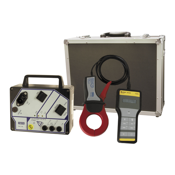
3. System description 3.1 System components On page 60, you will find a detailed overview of the scope of delivery of the EDS309x versions. The following illustration provides a choice of the possible components. 3.1.1 Overview of system components The primary task of the EDS309… is insulation fault location in IT systems. For this purpose the individual components of the EDS309……
-
Page 12: Insulation Fault Location Equipment Type List
– Insulation fault location in IT systems up to AC 42…460 Hz, 20…575 V and DC 20…504 V – Insulation fault location using AGE185 up to AC 42…460 Hz, 500…790 V and DC 400…960 V EDS3090: Can be used in IT systems in which a locating current injector PGH471 or an IRDH575 is already …
-
Page 13: Accessories
This state- ment also applies to measuring clamps or measuring current transformers from the Bender range that are not expressly intended to be used with the EDS309…. Along with the measuring clamps supplied, it is allowed to connect to the EDS195P the following measuring current transformers from the Bender series: WF……
-
Page 14: Function Of The System Components
2 m long. The connection to the EDS195P is made using a BNC connection. The following table summarises the most important data for the usage of the different measuring clamps. Main circuit Control circuit (EDS3090…, 3092…, 3096…) (EDS3091…) Measuring PSA3020, PSA3052, PSA3165 PSA3320, PSA3352…
-
Page 15: Coupling Device Age185
For example the locating current on the EDS3090 is limited to maximum 25 mA; with the setting = 10mA it is limited to 10 mA. During planning it is to be ensured that there are no system com- ponents in which this locating current could cause a reaction involving damage in unfavourable cir- cumstances.
-
Page 16: Schematic Diagram Eds System
System description 3.3.1 Schematic diagram EDS system IT-System L1(L+) L2(L-) PSA… EDS195P PGH… EDS195P Insulation fault locator PGH… Locating current injector IT system voltage PSA… Measuring clamp Insulation fault Protective earth conductor 3.3.2 Test cycle The locating current pulse cycle has a duration of 6 seconds. The PGH… sends alternating positive and negative locating current pulses.
-
Page 17: Definitions
System description 3.3.3 Definitions = Locating current that flows through the locating current injector while the fault location is running (EDS mode). = Locating current measured by the insulation fault locator (EDS mode). ΔL = Residual current produced by an insulation fault (RCM mode). Δn 3.3.4 Currents in the EDS system…
-
Page 18: Operating Principle For Residual Current Measurement (Iδn)
System description 3.4 Operating principle for residual current measurement (I Δn In the RCM mode the EDS309… operates based on the principle of residual current measurement. In this case only the insulation fault locator EDS195P and a measuring clamp are used, the locating cur- rent injector PGH18……
-
Page 19: Considerations Prior To Use
4. Considerations prior to use 4.1 How does the equipment for insulation fault location work The equipment comprises a locating current injector PGH18… and an insulation fault locator EDS195P with measuring clamp PSA3… connected. Functional sequence Insulation fault location is started by activating the locating current injector PGH18… …
-
Page 20: Requirements For Reliable Insulation Fault Location
«I >10 A». Δ This statement applies to the system frequencies 50/60/400 Hz for the EDS3090, EDS3090PG, EDS3090PG-13, EDS3092PG, EDS3096PG-13, EDS3096PV and EDS3096PG. – If the residual currents measured in control circuits exceed 1 A, the EDS195P outputs the alarm message «I…
-
Page 21
Considerations prior to use Frequency range Insula on fault loca on EDS195P Permissible Frequency and Residual current range Frequency [Hz] Abb. 4.3: Fault curve: A residual current of 2 A at 10 Hz is outside the permitted frequency range (red dot) ==> a valid measurement is not possible! There must be no connections between outgoing circuits downstream of measuring clamp because such connections will produce interfering residual… -
Page 22: Reduced Locating Current
In comparison to DC systems the related factor in AC systems is 0.5 and in 3AC systems 0.67. For this reason set the response value on the EDS195P for usage in AC and 3AC systems as follows: Settings Main circuit Control circuit PV system EDS3090 EDS3091 EDS3090PG Equipment for EDS3091PG EDS3090PG-13 EDS3096PV…
-
Page 23: Response Characteristics For Main Circuits In 3Ac Systems
Considerations prior to use The characteristics below enable you to simply determine a practical response value for the EDS195P. If the insulation monitoring device in a monitored system indicates an alarm message, manual insulation fault location can be started. Proceed as follows: 1.
-
Page 24: Response Characteristics For Main Circuits In Ac Systems
Considerations prior to use 4.4.2 Response characteristics for main circuits in AC systems AC 42V AC 110V 10mA 10mA Ce [uF] Ce [uF] AC 230V AC 400V 10mA 10mA Ce [uF] Ce [uF] 4.4.3 Response characteristics for main circuits in DC systems DC 60V DC 24V 10mA…
-
Page 25: Response Characteristics For Control Circuits In Ac Systems
Considerations prior to use 4.4.4 Response characteristics for control circuits in AC systems AC 42V AC 110V 0,2mA 0,2mA 0,5mA 0,5mA Ce [uF] Ce [uF] AC 230V 0,2mA 0,5mA Ce [uF] 4.4.5 Response characteristics for control circuits in DC systems DC 24V DC 60V 0,2mA…
-
Page 26
Considerations prior to use EDS309x_D00012_03_M_XXEN/11.2014… -
Page 27: Connecting The Locating Current Injector
5. Connecting the locating current injector Hazard due to excessively high locating voltage! Check the information on the nameplate to ensure the devices to be connected are suitable for the supplying system. The operation of the PGH18… and possi- bly the power supply unit with an incorrect supply voltage can cause irreparable CAUTION damage to the devices.
-
Page 28: Connection To A Live It System
Connecting the locating current injector 5.3 Connection to a live IT system Risk of electric shock! On touching live uninsulated conductors, death or serious injury may be caused. For this reason prevent any physical contact with active conductors and follow DANGER the rules for working on electrical systems.
-
Page 29: Connection To A Pv System
Connecting the locating current injector 5.4 Connection to a PV system Risk of electric shock! On touching live uninsulated conductors, death or serious injury may be caused. For this reason prevent any physical contact with active conductors and follow DANGER the rules for working on electrical systems.
-
Page 30
Connecting the locating current injector For insulation fault location within the junction box, it is essential that the ± cables of a string are ar- ranged in a way that the measuring clamp PSA30… can be put around the cables. Insulation faults in the strings can be localised by means of two measuring clamps connected in par- allel and an EDS-SET. -
Page 31: Operation
6. Operation 6.1 Short description of insulation fault location (EDS mode) Risk of electric shock! On touching live uninsulated conductors, death or serious injury may be caused. For this reason avoid any contact whatsoever with active conductors on posi- DANGER tioning the measuring clamp.
-
Page 32: Displays And Controls On The Pgh18
Operation 6.4 Displays and controls on the PGH18… ON/OFF switch, switch on or off locating current Changeover switch for maximum locating current values: 25/10 mA or 2.5/1 mA Not shown: magnetic strip on rear of housing for fastening to metal items (e.g. switch cabinet) 3 sockets for coupling to system Socket for PE connection…
-
Page 33: Displays And Controls On The Eds195P
Operation 6.5 Displays and controls on the EDS195P EDS195P EDS195P ISOSCAN® EDS195P EDS195P Bender GmbH&CoKG Bender GmbH&CoKG D-35305 Grünberg D-35305 Grünberg Δs ALARM ALARM Δn HOLD INFO HOLD INFO RESET MENU RESET MENU BNC connection for measuring clamp LC display, illuminated…
-
Page 34: Operating The Eds195P
The self-test is started after switching on. If the self-test is completed normally «No CT connected» appears. 2. You can switch off the device by pressing the On-Off button for around 2 s. EDS195P BENDER GmbH&CoKG D-35305 Grünberg >>>Self test<<< CT in rest pos.! >>…
-
Page 35: Changing The Measuring Clamp
Operation 6.6.2 Changing the measuring clamp Two methods can be used to change the measuring clamp. Changing with EDS195P switched off: – Disconnect clamp no longer required – Switch on EDS195P – Wait for «No CT connected» message – Set required clamp type –…
-
Page 36: Significance Of The Display Elements
Operation 6.6.7 Significance of the display elements The elements shown relate to the EDS mode (I ). This mode is used for insulation fault location. ΔL = 8mA Resp. = 5mA PSA30xx Indication of the locating current pulse: = Positive pulse, = Pause or no measurement possible when permanently displayed = Negative pulse 29…
-
Page 37: Standard Display For Eds Measurement (Iδl) With Cable In The Clamp
Operation 6.7.1.2 Standard display for EDS measurement ( I ) with cable in the clamp ΔL The display is indicating a measured fault current I of 3 mA. A measurement in progress is indicated ΔL by the change in the polarity of the measuring pulse ( with a pause (- — -) in between.
-
Page 38: Indication Of Device And Measuring Errors
Most of the settings are made on the menu. If this is not the case, the setting is marked with (button). ΔL Operating mode (button): (EDS mode = insulation fault location) Current transformer (button): Measuring clamp PSA3052 (for EDS3090 and 3096) Measuring clamp PSA3352 (for EDS3091) Illumination (button): Fault memory: Buzzer: Response value I with PSA30…:…
-
Page 39: Menu Structure
Operation 6.11 Menu structure The menu structure is shown schematically in the following. or explanation Level 1 Level 2 Level 3 1. Exit 1. Exit 2. Settings ΔL Δ 2. I ALM: 0.2…10 mA Response value measured locating current I Δ…
-
Page 40: Navigating In The Menu
Operation 6.11.1 Navigating in the menu — Open the menu using MENU — Select a menu item MENU or accept a value using OK — Navigate up or down in the menu HOLD RESET — Increase or reduce values ESC: INFO — Return from the last menu item selected — Discard modified setting without saving…
-
Page 41: Menu Item: System
Operation 6.11.3 Menu item: System Use this menu item to select the language for the user interface and to set the correct date and time. The date format can be changed. You can adjust the quality of the display by adjusting the contrast. Level 3 or explanation Level 1 Level 2…
-
Page 42: Menu Item: Iδn Logger
Operation 6.11.6 Menu item: I logger Δ Using this menu item you can check the measured values recorded automatically during a residual current measurement. The data records are numbered and contain the following information: The start time for the measurement and the change in the residual current monitored …
-
Page 43
Operation 3. Connect the PGH18… to a suitable power supply using the power cable supplied (see name- plate). 4. If there is an insulation monitoring device with an Ohmic internal resistance < 120 kΩ in the IT system to be checked, disconnect it from the system to be checked on all poles. It is not suffi- cient to switch off the power supply to the insulation monitoring device. -
Page 44
Operation 12. Start the insulation fault location from the main distribution area of the IT system. Place the measuring clamp around all system conductors, but not the PE conductor. During each meas- urement wait one test cycle (approx. 30 seconds). A flashing alarm LED on the EDS195P signals an insulation fault after (from the point of view of the locating current injector) the measuring clamp. -
Page 45: Insulation Fault Location In A System With A Permanently Installed Eds System
(IRDH575, PGH47…). The PGH18… is not required for this application. The PGH18… is not included in the items supplied with the EDS3090 and EDS3091. Insulation fault location is therefore only possible in electrically live IT systems. Also follow the operating instruc- tions for the permanently installed EDS system.
-
Page 46
Operation 7. Start the insulation fault location in the outgoing circuit of the IT system already detected as faulty. Place the measuring clamp around all system conductors, but not the PE conductor. During each measurement wait one test cycle (approx. 30 seconds). A flashing alarm LED on the EDS195P signals an insulation fault after (from the point of view of the locating current injector) the measuring clamp. -
Page 47: Insulation Fault Location In Diode-Decoupled Dc Systems
Operation 6.12.3 Insulation fault location in diode-decoupled DC systems In diode-decoupled DC systems equalising currents occur in and between the decoupled circuits. The direction and magnitude of these equalising currents is dependent on voltages in the system, the characteristics of the decoupling diodes and the characteristics of the loads. On the usage of the insulation fault location system EDS309……
-
Page 48
Operation – Pay attention to identical directions of flow on the two measuring clamps (see connection diagram). For this purpose the measuring clamps are marked with an arrow Place the two measuring clamps successively and systematically around all parallel outgoing cables for loads. -
Page 49: Usage Of The Eds195P As A Residual Current Meter
Operation 6.12.4 Usage of the EDS195P as a residual current meter The EDS195P can be used as a residual current meter up to AC 10 A in TN and TT systems. Residual current measurement is only possible in electrically live systems. The locating current injector PGH18……
-
Page 50: Indication Of The Harmonics During Residual Current Measurement
Operation Possible error messages Self test error: – Incorrect current transformer type set – EDS195P hardware faulty – Clamp moved while the indication «>>>Self test<<<» was displayed – An interfering residual current is flowing through the clamp – There is a PGH locating pulse acting on the clamp No CT connected: …
-
Page 51: Coupling Device Age185 For Higher System Voltages
Operation 6.13 Coupling device AGE185 for higher system voltages This option is available for the variants EDS3090PG, EDS3090PG-13 and EDS3096PG with the locat- ing current injectors PGH185 and PGH186. The coupling device AGE185 expands the nominal volt- age range of the insulation fault location system EDS309… The AGE185 reduces the losses in the locating current injector PGH18……
-
Page 52: Power Supply For The Eds195P
Operation 6.14 Power supply for the EDS195P The device is supplied with power using 3 NiMH cells of 1.2 V each or 3 mignon cells of type LR6 AA of 1.5 V each. The power supply unit is not allowed to be connected with non-rechargeable batteries …
-
Page 53: Technical Specifications
7. Technical specifications 7.1 Technical specifications for the system EDS309… The technical specifications stated in this section apply to the components PGH18…, EDS195P, AGE185. Environment/EMC EMC……………………………………IEC 61326-2-4 Operating temperature ………………………………-10…+ 55 °C Climatic classes acc. to IEC 60721: Stationary use (IEC 60721-3-3) ……………………..3K5 (without condensation or icing) Transport (IEC 60721-3-2) ……………………….2K3 (without condensation or icing) Long-term storage (IEC 60721-3-1) …………………….1K4 (without condensation or icing)
-
Page 54: Technical Specifications Eds195P
Technical specifications Locating current PGH183: Locating current max., can be selected…………………………….1/2.5 mA PGH185/186: Locating current max., can be selected……………………………10/25 mA PGH183/185/186 Test cycle ……………………………………..2 s Pause duration ……………………………………. 4 s Locating voltage PGH186……………………………………..DC 50 V Other Degree of protection of built-in components DIN EN 60529 (VDE 0470-1) …………………… IP40 Enclosure material…………………………………..ABS plastic Flammability class………………………………….UL94V-0 Weight……………………………………..
-
Page 55: Technical Specifications Measuring Clamps
Technical specifications Measuring circuit, residual current With measuring clamps………………………….. PSA3020, PSA3052, PSA3165 Measuring range …………………………..5 mA…10 A (crest factor up to 3) Response sensitivity adjustable……………………….10 mA…10 A (100 mA)* Δn Measuring clamps ………………………………PSA3320, PSA3352 Measuring range …………………………..2 mA…2 A (crest factor up to 3) Response sensitivity adjustable………………………….
-
Page 56: Technical Specifications Age185
Technical specifications 7.5 Technical specifications AGE185 Insulation co-ordination according to IEC 60664-1 Rated insulation voltage ……………………………….. AC 1000 V Rated impulse voltage/degree of pollution …………………………..4 kV/3 Nominal system voltage ………………….3AC/AC 42…460 Hz, 500…790 V, DC 400…960 V Other Degree of protection of built-in components DIN EN 60529 (VDE 0470-1) ……………………
-
Page 57: Dimension Diagrams
Technical specifications 7.7 Dimension diagrams All dimensions are given in mm. Aluminium case AGE185 EDS309x_D00012_03_M_XXEN/11.2014…
-
Page 58: Status Word
Technical specifications 7.8 Status word The status word can be checked by pressing the «INFO» button several times. This word contains the current configuration and provides an error code if there is a device error. CT type p -> PSA30xx P ->…
-
Page 59: Ordering Data Including Accessories
Technical specifications 7.9 Ordering data including accessories EDS309x_D00012_03_M_XXEN/11.2014…
-
Page 60: Component List
Technical specifications 7.10 Component list EDS-Set, optional Measuring clamps 115 mm, optional Measuring clamps 52 mm Measuring clamps 20 mm Coupling device, optional (EDS3096PV only: in the scope of delivery) Safety claw grip, green/yellow Safety claw grip, black Safety measuring cable, green/yellow Safety measuring cable, black Supply cable for PGH18…
-
Page 61: Frequently Asked Questions
8. Frequently Asked Questions The ISOMETER® indicates an insulation fault but this fault cannot be located using the EDS309…. What could cause this problem? – Individual outgoing circuits in the IT system monitored may be earthed. Check all outgoing circuits for unintentional earthing.
-
Page 62
Frequently Asked Questions EDS309x_D00012_03_M_XXEN/11.2014… -
Page 63: Index
INDEX — Settings 40 — System 41 Accessories EDS mode 14 Menu structure 39 — optional 13 EDS195P AGE185 51 — controls 33 Alarm is also output audibly 36 Alarm LED 33 Navigating in the menu on the EDS195P Alarms during EDS measurement or RCM Factory settings 38 measurement 37 Fault circuit 15…
-
Page 64
INDEX Selecting the current transformer 33 Selecting the operating mode 34 Setting language 39 Settings 40 Significance of the display elements 36 Standard display for EDS measurement 37 Standard displays on the EDS195P 36 Standards 56 Status word 58 Switch on-off 34 System components 11 Systems — electrically isolated 27… -
Page 68
Bender GmbH & Co. KG Londorfer Str. 65 • 35305 Grünberg • Germany Postfach 1161 • 35301 Grünberg • Germany Tel.: +49 6401 807-0 Fax: +49 6401 807-259 E-Mail: info@bender.de Web: http://www.bender.de…
|
Detail Specifications: 1290/1290370-eds3090.pdf file (19 Apr 2023) |
Accompanying Data:
Bender EDS3090 Measuring Instruments PDF Manual (Updated: Wednesday 19th of April 2023 03:47:52 PM)
Rating: 4.3 (rated by 40 users)
Compatible devices: VME421H, iso685-S Series, grass valley KMX-4911, ISOMETER IR1575H, ISOMETER iso685-D-P, ISOMETER isoLR275, COMTRAXX COM465ID, RCMB-35-30 Series.
Recommended Documentation:
Text Version of Manual
(Ocr-Read Summary of Contents, UPD: 19 April 2023)
Recommended Instructions:
GLT3057RB01, FT-PWR, APLDVD21568 FD, Convertible Bump Case none, PLS342P


-
Auto-Ohm 200 S3 / DMOM-200 S3 / DMOM-600 True DC Digital Micro-Ohmmeters USER’S MANUAL Vanguard Instruments Company, Inc. 1520 S. Hellman Ave. Ontario, California 91761, USA TEL: (909) 923-9390 FAX: (909) 923-9391 August 2019 Revision 2.4 …
Auto-Ohm 200 S3 66
-
INSTALLATIONTo install the SX-200/400 or SX-600/1000 simply connect coaxial cable directed to the antenna connector marked «ANT»,andThe cable coming from the transmitter or from the linear amplifier to the connector marked «TX»SX-200/400 or SX-600/1000 is ready to operate.POWER MEASUREMENTSI Select the RANGE (3) switch on the end-scale position value …
SX-400 2
-
PortabLe USB RecorderTRAGBARER USB-REKORDERGRABADOR PORTATIL POR USB ENREGISTREUR PORTABLE USB In the USA: If you experience problems with this unit, please go to http://www.geminidj.com/support.html or call 1-732-738-9003 for Gemini Customer Service. Do not attempt to return this equipment to your deal-er. Gemini stands behind their products with an industry-leading 3 y …
iKEY 38
-
CYFROWY MIERNIK TABLICOWYDIGITAL PANEL METERN24, N25INSTRUKCJA OBSŁUGI — SZYBKI STARTPełna wersja instrukcji dostępna naFull version of user’s manual available at www.lumel.com.plUSER’S MANUAL — QUICK STARTPLENZeskanuj mnieZeskanuj kod Scan the code …
N24S 24
Additional Information:
Popular Right Now:
Operating Impressions, Questions and Answers:
Is the category for this document correct?
- Engineering & Technology
- Electrical Engineering
Thank you for your participation!

No more boring flashcards learning!
Learn languages, math, history, economics, chemistry and more with free Studylib Extension!
- Distribute all flashcards reviewing into small sessions
- Get inspired with a daily photo
- Import sets from Anki, Quizlet, etc
- Add Active Recall to your learning and get higher grades!
Add to Chrome
It’s free
Код товара: Артикул:
117086
ТОВАР В НАЛИЧИИ
 Добровольная сертификация

Гарантия: 1 год
Доставка и оплата
Ваш регион: Москва
Самовывоз: ул. Подольских Курсантов, д. 17, корп. 2, оф. 207
Доставка курьером: 1-3 рабочих дня, 300 руб.
При заказе свыше 30000 руб. — доставка бесплатно
Bender ISOSCAN EDS3090PG-13 представляет собой портативную систему поиска повреждений изоляции в незаземлённых сетях (сетях IT). Все необходимые компоненты хранятся и переносятся в прочном и удобном алюминиевом кейсе.
Особенности и преимущества
- Портативные системы поиска повреждений изоляции
- Для сетей питания и оперативного тока
- Клещи с внутренним диаметром 20/52/115 мм
- Контроль дифференциальных токов в сетях TN и TT
- Универсальная концепция
- Мобильные системы определения места повреждения изоляции для ИТ-систем переменного тока 42…460 Гц 0…790 В/постоянного тока 0…960 В или обесточенных систем
- Измерение остаточного тока в системах TN/TT
- Использование в основных цепях и цепях управления
- Измерительные зажимы 20/52 мм (опционально 115 мм)
- Прочный алюминиевый корпус, удобный для переноски
- Испытательные устройства PGH18… с переменным испытательным током 1…25 мА
- Встроенное испытательное напряжение для обесточенных систем (PGH186)
Особенности и преимущества устройства для оценки неисправностей изоляции EDS195PM
- ЖК-дисплей с подсветкой, 3 x 16 символов
- Измерительные зажимы 20/52 мм входят в комплект поставки
- Питание от аккумулятора (поставляется с блоком питания)
- Значение срабатывания место повреждения изоляции 2…10 мА для основных цепей
- Значение отклика место повреждения изоляции 0,2…1 мА для цепей управления
- Значение срабатывания измерение остаточного тока 10 мА…10 А
- Выбираемый режим работы местоположение повреждения изоляции/измерение остаточного тока
Области применения
- IT-системы без установленной системы определения местоположения неисправностей изоляции (EDS)
- EDS3090PG для основных цепей до переменного тока 20…575 В 42…460 Гц, постоянного тока 20…504 В с AGE185 до переменного тока 500…790 В 42…460 Гц, постоянного тока 400…960 В
- EDS3091PG для цепей управления до переменного тока 20…265 В 42…460 Гц, постоянного тока 20…308 В
- EDS3096PG для основных цепей в ИТ-системах до переменного тока 0…575 В 42…460 Гц, постоянного тока 20…504 В, со всеми отключенными полюсами
- EDS3096PV для фотоэлектрических систем с PGH186 до 20…575 В 42…460 Гц, постоянного тока 20…504 В с AGE185 до переменного тока 500…790 В 42…460 Гц, постоянного тока 400…960 В
- IT-системы с установленной системой определения местоположения неисправностей изоляции (EDS)
- EDS3090 для основных цепей с установленной системой EDS460/490
- EDS3091 для цепей управления с установленной системой EDS461/491
| Тип | Произвольное напряжение | Номинальное напряжение |
| EDS3090 | — | AC 20…575 V, 42…460 Hz и DC 20…504 V |
| EDS3090PG | AC 230 V, 50…60 Hz | AC 20…575 V, 42…460 Hz и DC 20…504 V |
| EDS3090PG-13 | AC 90…132 V, 50…60 Hz | AC 20…575 V, 42…460 Hz и DC 20…504 V |
| EDS3091 | — | AC 20…265 V, 42…460 Hz и DC 20…308 V |
| EDS3091PG | AC 230 V, 50…60 Hz | AC 20…265 V, 42…460 Hz и DC 20…308 V |
| EDS3091PG-13 | AC 90…132 V, 50…60 Hz | AC 20…265 V, 42…460 Hz и DC 20…308 V |
| EDS3092PG | AC 230 V, 50…60 Hz AC 230 V, 50…60 Hz |
AC 20…265 V, 42…460 Hz и DC 20…308 V AC 20…575 V, 42…460 Hz и DC 20…504 V |
| EDS3096PG | AC 230 V, 50…60 Hz | AC 0…575 V, 42…460 Hz и DC 0…504 V |
| EDS3096PG-13 | AC 90…132 V, 50…60 Hz | AC 0…575 V, 42…460 Hz и DC 0…504 V |
| EDS3096PV | AC 230 V, 50…60 Hz | AC 20…575 V, 42…460 Hz и DC 20…504 V |
| Тип | Устройство для оценки неисправностей изоляции | Устройство для проверки неисправности изоляции | Измерительные зажимы 200 мм | Измерительные зажимы 52 мм |
| EDS3090 | EDS195PM | — | PSA3020 | PSA3052 |
| EDS3090PG | EDS195PM | PGH185 | PSA3020 | PSA3052 |
| EDS3090PG-13 | EDS195PM | PGH185-13 | PSA3020 | PSA3052 |
| EDS3096PG | EDS195PM | PGH186 | PSA3020 | PSA3052 |
| EDS3096PG-13 | EDS195PM | PGH186-13 | PSA3020 | PSA3052 |
| EDS3091 | EDS195PM | — | PSA3320 | PSA3352 |
| EDS3091PG | EDS195PM | PGH183 | PSA3320 | PSA3352 |
| EDS3091PG-13 | EDS195PM | PGH183-13 | PSA3320 | PSA3352 |
| EDS3092PG | EDS195PM | PGH183 PGH185 |
PSA3320 PSA3020 |
PSA3352 PSA3052 |
- Система поиска повреждений изоляции в незаземлённых сетях
- Паспорт
- Руководство по эксплуатации
- Гарантийный талон
- Упаковка
По заказу
- Соединительное устройство для расширения диапазона напряжений PGH185/186 AGE185
- Принадлежности для определения места неисправности в системах с диодной развязкой EDS165-SET
- Измерительный зажим 115 мм PSA3165