Инструкция к эхолоту Lowrance X-4 и X-4 Pro
![]()
Скачать
 инструкция, lowrance
 21.02.2014, 4301 просмотр.
-
Contents
-
Table of Contents
-
Troubleshooting
-
Bookmarks
Quick Links
X-4 Pro
Fish-Finding Sonar
Installation and Operation
Instructions
Related Manuals for Lowrance X-4 Pro
Summary of Contents for Lowrance X-4 Pro
-
Page 1
X-4 Pro Fish-Finding Sonar Installation and Operation Instructions… -
Page 2
Navico. Any unauthorized commercial distribution of this manual is strictly prohibited. Lowrance is a registered trademark of Navico. ® Navico may find it necessary to change or end our policies, regulations, and special offers at any time. -
Page 3: Table Of Contents
Table of Contents Capabilities and Specifications: X-4 Pro ……..1 Preparations ………………2 Installation ………………. 2 Recommended Tools and supplies ……….. 3 Selecting a Transducer Location …………. 3 How low should you go? …………..5 Shoot-Thru-Hull vs. Transom Mounting ……..5 Transom Transducer Assembly and Mounting ……
-
Page 4
Noise Rejection and ASP™ …………..37 Depth Display ………………39 Temperature Display …………….. 39 Voltage ………………..40 Backlight ………………… 40 Contrast ………………..40 Simulator ……………….. 40 Set Language ………………41 Software Information …………….. 41 Reset Options………………41 Troubleshooting …………….42… -
Page 5: Capabilities And Specifications: X-4 Pro
Capabilities and Specifications: X-4 Pro General Case size: ……5.8″ H x 4.3″ W x 2.5″ D (14.7 cm H x 10.8 cm W x 6.6 cm D) sealed, waterproof; suitable for saltwater use. Display: ……High-contrast Film SuperTwist LCD. Di- agonal viewing area: 4″…
-
Page 6: Preparations
NOTICE! The storage temperature for your unit is from -4 degrees to +167 degrees Fahrenheit (-20 degrees to +75 degrees Celsius). Extended storage in temperatures higher or lower than specified will damage the liquid crystal display in your unit. This type of damage is not covered by the warranty.
-
Page 7: Recommended Tools And Supplies
Depending on your sonar unit’s connectors, your transducer cable may also have the sonar unit’s power cable attached to it. If that is the case, be sure to install the transducer first, before connecting the power cable to a power source. See the instructions later in this manual for connect- ing the power cable to a battery or other power supply.
-
Page 8
NOTE: Some aluminum boats with strakes or ribs on the outside of the hull create large amounts of turbulence at high speed. These boats typically have large outboard motors capable of propelling the boat at speeds faster than 35 mph. Typically, a good transom location on aluminum boats is between the ribs closest to the engine. -
Page 9: How Low Should You Go
How low should you go? For most situations, you should install your Skimmer transducer so that its centerline is level with the bottom of the boat hull. This will usually give you the best combination of smooth water flow and protec- tion from bangs and bumps.
-
Page 10: Transom Transducer Assembly And Mounting
varies from hull to hull, even from different installations on the same hull. This is caused by differences in hull lay-up and construction. Second, the transducer angle cannot be adjusted for the best fish arches. This can be a problem on hulls that sit with the bow high when at rest or at slow trolling speeds.
-
Page 11
Reassemble the transducer and bracket and place them against the transom. Again, check to see if you can move the transducer so it’s pa- rallel with the ground. If you can, then go to step 3. If it doesn’t, repeat step 2, but use a different alignment letter. -
Page 12
Transom Transom Position transducer mount on transom and mark mounting holes. Side view shown at left and seen from above at right. 5. Attaching transducer to transom. Remove the transducer from the bracket and re-assemble it with the cable passing through the bracket over the bolt as shown in the following figures. -
Page 13
Bottom hull Deep-«vee» hull Flat-bottom hull Align transducer centerline with hull bottom and attach to transom. 6. Route the transducer cable through or over the transom to the sonar unit. Make sure you leave some slack in the cable at the transducer. -
Page 14: Trolling Motor Bracket Installation
Trolling Motor Bracket Installation 1. Attach the optional TMB-S bracket to the transducer as shown in the following figure, using the hardware supplied with the transducer. (Note: The internal tooth washer is supplied with the TMB-S.) TMB-S bracket Internal tooth washer Bolt Flat washer Attach motor mounting bracket to transducer.
-
Page 15: Transducer Orientation And Fish Arches
Transducer Orientation and Fish Arches If you do not get good fish arches on your display, it could be because the transducer is not parallel with the ground when the boat is at rest in the water or at slow trolling speeds. Partial fish arches Transducer aimed Transducer aimed…
-
Page 16
ers. The sonar signal must pass through solid fiberglass. A successful transducer installation can be made on hulls with flotation materials (such as plywood, balsa wood or foam) between layers of fiberglass if the material is removed from the chosen area. See the figure below. WARNING: Do not remove any material from your inner hull unless you know the hull’s composition. -
Page 17: Testing Determines Best Location
Testing Determines Best Location Ideally, the shoot-thru transducer should be installed as close to the transom as possible, close to the centerline. This will give you the best performance during high speed maneuvers. 1. Anchor the boat in about 30 feet of water. Add a little water to the sump of the boat.
-
Page 18: Shoot-Thru-Hull Installation
hull. This is especially true if you have to turn sensitivity all the way up to get a decent bottom signal. 4. Most people can get good results by following steps 1 through 3, so this step is optional. If you want to make an extra effort to be absolutely sure that your selected location will work under all conditions, make a test run with the boat on plane and observe the bottom signal.
-
Page 19: Power Connections (Permanent Mount Only)
2. The epoxy consists of the epoxy itself and a hardener. Remove the two compounds from the package and place them on the paper plate. Thoroughly stir the two compounds together until the mixture has a uniform color and consistency. Do not mix too fast or bubbles will form in the epoxy.
-
Page 20: Mounting The Sonar Unit: In-Dash, Bracket Or Portable
This unit can be installed in a dash with the optional FM-6 in- dash adapter kit. The FM-6 kit includes an instruction sheet, part 988- 0147-631, which contains a template for cutting out the mounting hole. This document can be downloaded free from www.lowrance.com.
-
Page 21: Bracket Installation
[2.77] Front view (left) and side view (right) showing dimensions of the X-4 Pro when mounted on quick release bracket. Drill a 1″ (25.4 mm) hole in the dash for the power/transducer and ac- cessory cables. The best location for this hole is immediately under the gimbal bracket location.
-
Page 22
Screw hole Power/transducer cable Cable slot X-4 Pro quick release mounting bracket. Slots in the base allow routing the cable from beneath the mount. Attach the unit to the bracket by first connecting the power/transducer and accessory cables. Then, hold the sonar unit vertically and slide it onto the bracket from above. -
Page 23: Portable Sonar Installation
Portable Sonar Installation Like many Lowrance products, the X-4 Pro is capable of portable opera- tion. It uses the optional PPP-12 portable power pack. The power pack and portable transducers expand the uses for your sonar.
-
Page 24: Installing The Batteries
Plug in the power/transducer cable and you’re ready to fish. The PPP- 12 has a quick-release mounting bracket built into the case. Installing the Batteries Open the case and lay it flat. (The latch is located below the handle.) Insert eight «AA» size batteries into the battery adapter and place it in the battery compartment.
-
Page 25: Portable Transducer Assembly
Ratchet To mount the sonar, slide the unit onto the bracket from above (left). To adjust the view, press and release spring-loaded ratchets while tilt- ing the unit (right). To adjust the viewing angle, pinch the quick-release mount’s ratchets with one hand, then tilt the unit with your other hand. Release the rat- chets and the unit locks into the new position.
-
Page 26
Make sure there is one washer on each side of the transducer, inside the bracket. Slide the other washer over the end of the bolt and screw on the nut. Screw the suction cup onto the bracket using the supplied screw and flat washer. -
Page 27: Portable Transducer Storage
Hull Portable transducer installed on boat transom. Portable Transducer Storage There is room inside the power pack for the portable transducer. When you’re finished fishing, tilt the sonar down to the storage position. Open the case and lay it flat. Unplug the power connector from the battery compartment socket.
-
Page 28: Operation
↓ (DOWN) ↑ (UP) this manual. You will use these keys to adjust most features and functions on the X-4 Pro. Memory This unit has permanent memory that saves the following user settings when power is turned off: Units of Measure, Temp Size, Depth Size, Fish I.D.
-
Page 29: Display
keys access these features, allowing you to customize unit set- MENU tings. To switch menus, press repeatedly. Press to clear menus MENU from the screen. The Backlight menu with backlight turned on. Display The lights will flash for about 10 seconds when the unit is turned on. The backlight menu will appear on the screen.
-
Page 30: Full Chart
Full Chart The unit’s default page, Full Chart shows all echoes scrolling across the full screen. The bottom signal scrolls across the screen from right to left. The line at the top of the screen represents the surface. The bottom depth —…
-
Page 31: Zoom
Depth Range menu with Manual setting selected (left). Range Size menu with 0-80 ft highlighted (right). Zoom The zoom feature enlarges all images on the screen by doubling the size of the echoes (a 2X zoom). For example, if the current auto depth range is 0 to 60 feet, Zoom will show an enlarged view of the water column from 30 feet to 60 feet, always keeping the bottom in view.
-
Page 32: Sensitivity
To turn off the zoom feature, repeatedly press until the menu MENU appears. Press ↑ to select , then press to clear the menu. The top of the depth range scale returns to zero. NOTE: Using the Zoom command while in auto Zoom mode will always en- large the echoes near the bottom, because auto Range always keeps the bottom displayed in the lower portion of the screen.
-
Page 33
Sensitivity set to manual mode (left). Sensitivity scroll bar (right). You can change the sensitivity level whether you are in Auto Sensitivity mode or Manual Sensitivity mode. The adjustment method works the same in both modes, but gives you slightly different results. To adjust sensitivity in Auto Mode: Repeatedly press until the… -
Page 34: Grayline
Fish arches These figures show results of different sensitivity levels on the same location. Fig. 1: Sensitivity at 98 percent, determined by Auto Sensitiv- ity. Typical of full auto mode. Fig. 2: Sensitivity set at 71 percent. Fig. 3: Sensitivity set at 47 percent. Fig. 4: Sensitivity set at 100 percent. ®…
-
Page 35: Chart Speed
is usually adequate for most conditions. Experiment with your unit to find the Grayline setting that’s best for you. To change the Grayline level, repeatedly press until the MENU RAYLINE scroll bar appears. Wider ® Thin or no Grayline ® Grayline A small amount of Grayline indicates a soft bottom (left), probably sand or mud.
-
Page 36: Frequency
better images as you decrease the chart speed to match the speed of your boat. If you are at anchor, ice fishing or fishing from a dock, experiment with a chart speed of 25 percent. If you are drifting slowly, try a chart speed of 50 percent.
-
Page 37: Fish I.d
Fish I.D.™ The Fish I.D.™ feature displays — as fish — targets that meet certain conditions. The microcomputer analyzes all echoes and eliminates sur- face clutter, thermoclines and other undesirable signals. The Fish I.D. feature displays symbols on the screen in place of the ac- tual fish echoes.
-
Page 38: Fishtrack
Fish I.D. mode and without to become more familiar with the feature. This unit’s default Fish I.D. setting is on. Fish I.D. is most handy when you are in another part of the boat or per- forming some task that prevents you from watching the sonar screen. Then, you can turn on Fish I.D.
-
Page 39: Depth Alarms
To turn on Fish I.D., repeatedly press until the menu ap- MENU pears. Press to select , then press . Repeatedly press ↓ MENU til the menu appears. Press to select , then press ↑ LARM To turn off fish alarm repeatedly press until the menu MENU…
-
Page 40: Deep Alarm
Press . The Shallow Alarm Value dialog box will appear. ↓ ALUE Use ↑ ↓ to enter the first number in the dialog box, then press MENU to move to the next digit. Repeat those steps until the desired DOWN depth has been entered in the dialog box.
-
Page 41: Battery Alarm
Battery Alarm To set the battery alarm depth, repeatedly press until MENU ATTERY appears. LARM Battery Alarm menu (left). Low Battery Alarm Value (right). Press the . The Low Battery Alarm Value dialog box will ↓ ALUE appear. Input a voltage value between 7 and 18 volts. Use the keys ↑…
-
Page 42
Noise Rejection menu. The ASP noise rejection feature is especially useful because, typically, it lets you operate the boat at all speeds without adjusting the sensitiv- ity or other controls. The ASP feature has three settings — Off, Low and High. When first turned on, noise rejection is set on low. -
Page 43: Depth Display
Depth Display Depth may be displayed on the screen in a small, medium or large size or can be turned off completely. To display Depth: Repeatedly press until the menu appears. Use to select ↑ ↓ MENU EPTH the size of the depth display. Press to clear the menu.
-
Page 44: Voltage
Voltage The Voltage menu allows you to display battery voltage on the screen in a small or medium size or can be turned off completely. To display battery voltage: Repeatedly press until the menu appears. Use to se- ↑ ↓ MENU OLTAGE lect the size of the voltage display.
-
Page 45: Set Language
Simulator menu (left). Languages menu (right). To use the simulator, repeatedly press until the menu MENU IMULATOR appears. Press to turn it on and press to clear the menu. Repeat ↑ the steps above to turn it off. The simulator automatically will be turned off when you power off the unit.
-
Page 46: Troubleshooting
Troubleshooting If your unit is not working, or if you need technical help, please use the following troubleshooting section before contacting the factory custom- er service department. It may save you the trouble of returning your unit for repair. For contact information, refer to the last page, just in- side the back cover of this manual.
-
Page 47
3. The water may be deeper than the sonar’s ability to find the bottom. If the sonar can’t find the bottom signal while it’s in the automatic mode, the digital sonar display will flash continuously. It may change the range to limits far greater than the water you are in. -
Page 48
vere cases, it can completely cover the screen with black dots, or cause the unit operate erratically, or not at all. To eliminate or minimize the effects of electrical noise, first try to de- termine the cause. With the boat at rest in the water, the first thing you should do is turn all electrical equipment on the boat off. -
Page 49
Notes… -
Page 50: How To Obtain Service
800-324-1354 8 a.m. to 5 p.m. Central Standard Time, M-F Lowrance Electronics may find it necessary to change or end our ship- ping policies, regulations, and special offers at any time. We reserve the right to do so without notice.
-
Page 51: Accessory Ordering Information
Accessory Ordering Information for all countries To order Lowrance GPS accessories such as computer cables or MMC cards, please contact: 1) Your local marine dealer or consumer electronics store. Most quality dealers that handle marine electronic equipment or other consumer electronics should be able to assist you with these items.
-
Page 52
Visit our web site: www.lowrance.com *988-10015-001*…
Содержание
- Общие сведения о моделях
- Описание и характеристики
- Информация на дисплее
- Предварительная настройка
- Отзывы
- Видео по теме
Современную рыбалку трудно представить себе без эхолота. Эти маленькие помощники уже давно вошли в арсенал рыбаков и заняли свою нишу в походном инвентаре многих любителей активного отдыха. Давно не секрет, что от качества подобных изделий, их функциональности и работоспособности зависит очень многое. Ведь часто бывает так, что единственным способом исследовать дно незнакомого водоёма, чтобы определить потенциальные рыбные места, является именно эхолот. Особенно это важно во время зимней рыбалки. Поэтому многие любители рыбной ловли предпочитают использовать не какие-то безымянные китайские изделия, а продукцию известных фирм. Такими устройствами являются эхолоты Lowrance X-4 и X-4 Pro от известного американского производителя.
Общие сведения о моделях
Каждый раз, выбирая тот или иной товар, хочется, чтобы он был и дешевый, и надежный. Это в равной степени касается абсолютно всех покупателей, независимо от их уровня доходов, и всех видов продукции, независимо от их ценовой категории. Американская компания Lowrance, уже более 60 лет занимающаяся выпуском эхолотов, именно так позиционирует свои популярные модели эхолотов серии «Х».
Эта серия присутствует на рынке уже более десятка лет. В настоящее время производство её прекращено, однако успех линейки был такой, что эхолотов было произведено более чем достаточно.
В настоящее время еще относительно большое их количество до сих пор не распродано. Данные эхолоты представляют собой недорогие приборы, обладающие тем не менее достаточной функциональностью, которой вполне хватает для оценки подводной обстановки.
Среди большого количества других моделей эхолотов трудно найти более приемлемый вариант по соотношению цена/качество. А известное имя их производителя является гарантией того, что данное приобретение не будет пустой тратой средств.

Кроме того, как и подобает любому нормальному производителю, Lowrance осуществляет реализацию своей продукции со всеми необходимыми комплектующими и аксессуарами. В комплект поставки, кроме самого эхолота и инструкции к нему, входят несколько приспособлений для крепления и все необходимые метизы.
В настоящее время эхолоты Lowrance X-4 можно купить в Москве примерно за 130–150 долларов. Цена версии X-4 Pro будет несколько выше: порядка 150–170 долларов.
Описание и характеристики
Данные модели обладают практически очень похожими характеристиками, однако, различия между ними весьма существенны. Основное, чем отличаются модели Lowrance X-4 и X-4 Pro – это тип датчика, используемого в трансдьюсере.
Обычная модель (Lowrance X-4) оснащена однолучевым датчиком Lowrance 200 kHz Skimmer, работающим на частоте 200 кГц и имеющим угол обзора 60 градусов. Более продвинутая версия эхолота – Lowrance X-4 Pro оснащается двулучевым датчиком Skimmer, имеющим частоты в 83 КГц и 200 КГц с углами излучения в 120° и 60° соответственно.
Датчики в этих моделях отличаются не только по частотам, но и по мощности излучаемого сигнала, что, естественно, отражается на максимальной рабочей глубине.
Датчик, используемый в Lowrance X-4, имеет постоянную мощность 100 Вт и пиковую 800 Вт. Датчик в модели Lowrance X-4 Pro является более «активным»: мощности его излучения равны 150 Вт и 1500 Вт соответственно. Максимальная глубина сканирования для обычной версии X-4 составляет 183 м, а X-4 Pro – 305 м.
Важно! Указанные величины мощности являются мощностью излучения в импульсе, средняя электрическая мощность, потребляемая прибором (вместе с датчиком) от аккумулятора, составляет от 10 до 30 Вт в зависимости от времени работы, используемых режимов, глубины водоёма, солёности воды и т. д.
Оба эхолота имеют степень водозащищённости IPX7.

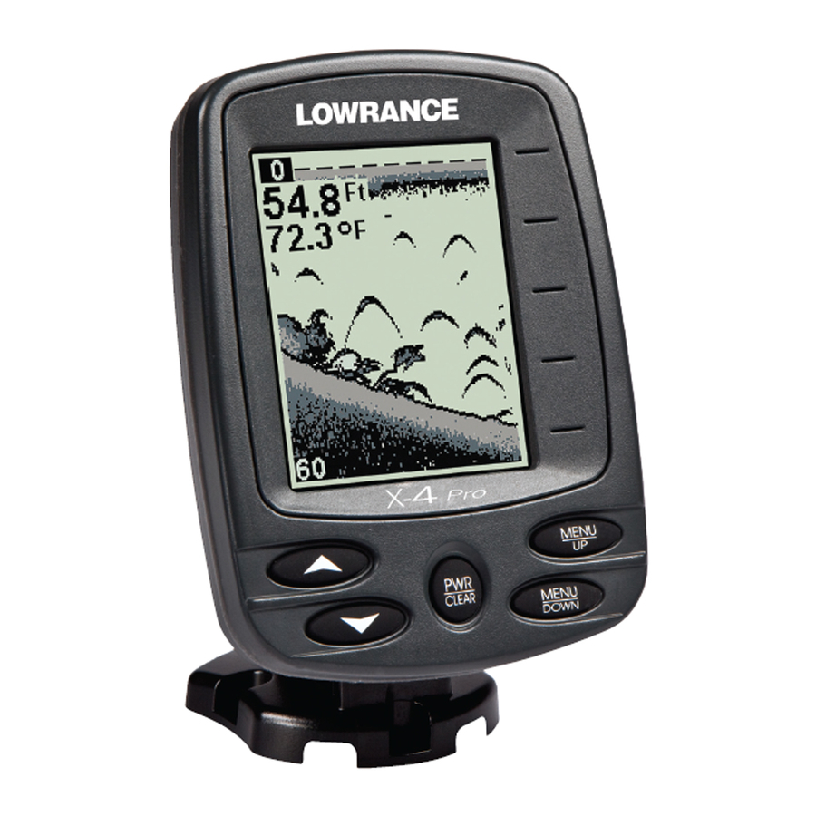
Вся получаемая от датчика информация выводится на встроенный в эхолот Lowrance X 4 черно-белый экран с размерами по диагонали 4 дюйма (10 см) и разрешением 240х160 точек.
В дисплее используется технология Super-twist, то есть фактически изображение на экране не чёрно-белое, а серое, имеющее 4 оттенка. Графическая информация, выводимая на дисплей, прекрасно читается при ярком свете солнца и подсвечивается в темное время суток, благодаря наличию встроенной подсветки. Возможности приборов обширны, и, кроме обнаружения рыбы, позволяют пользователю: определять структуру дна, глубину водоема, распознавать виды рыб.
Звуковая сигнализация оповещает пользователя эхолота Lowrance о приближении лодки к мели и обнаружении рыбы в поле обзора датчика-излучателя. Функция Lowrance automatic ASP позволяет получать изображение самого высокого качества на экране устройства. Кроме этого, в конструкцию датчика-излучателя встроен датчик для измерения температуры воды.
Датчики обеих моделей эхолотов может закрепляться на плавательном средстве несколькими способами:
- на транец лодки – стандартная и наиболее распространённая схема установки при помощи специального крепления, идущего в комплекте;
- на троллинговый мотор;
- на дно лодки;
- крепление к борту лодки при помощи присоски.
Важно! В зависимости от места установки датчика могут понадобиться различные инструменты.
При любом способе монтажа оба эхолота надежно работают на скоростях до 110 километров в час. Для электропитания прибора используется электросеть напряжением 10–17 вольт, при этом мощность производитель рекомендует использовать в общей цепи питания эхолота и датчика предохранитель на 3 А.
Информация на дисплее
Дисплей представляет собой место отображения информации двух типов:
текстовой (температура, глубина, уровень заряда батареи);
графической (изображение дна и рыбы).

Отображение текстовой информации производится в левом верхнем углу экрана. Графическая информация выступает как бы «фоновым» изображением.
Глубина отображается визуально в виде тёмной полоски относительно верха экрана, принимаемого за уровень поверхности водоёма. Чтобы не запутаться, нулевой уровень (уровень поверхности) отображается символом «0» непосредственно в левом верхнем углу.
При движении лодки текстовая и графическая информация меняются. На месте текста с данными о глубине, температуре и уровне заряда просто появляются их новые значения. Графическая же информация изменяется гораздо интереснее.
Ранее нарисованное изображение сдвигается влево, а с правого края начинает изображаться новый участок дна. Поскольку разрешение экрана составляет по горизонтали 160 точек, эхолот запоминает последние 160 измерений, что позволит достаточно детально отобразить визуальную картинку дня.
Предварительная настройка
Приборы очень просты в повседневной эксплуатации. Пользователь сможет легко настроить эхолот перед началом работы с помощью кнопок управления, вынесенных на лицевую панель прибора, при этом настройки сохранятся в памяти устройства даже при отключении электропитания.
Изначально эхолоты Lowrance X-4 и X-4 Pro выходят с базовыми настройками, которые для работы, мягко говоря, не предназначены. Рассмотрим последовательность действий, необходимую для того, чтобы настроить эхолот.
Вначале следует включить эхолот при помощи кнопки «Power». После включения необходимо войти в меню и установить русский язык. Так будет проще разобраться с навигацией по пунктам меню. Это можно сделать, нажимая кнопку «MenuUp» и найдя пункт «Languages». В нём выбирается русский язык при помощи стрелок. Подтверждение выбора осуществляется кнопкой «MenuUp».
Далее осуществляется настройка основных параметров:
- Диапазон глубин: авто;
- Масштабирование: выключено;
- Чувствительность (размер исследуемых объектов): от 50 до 70%;
- Частота: 200 КГц для 120°, 83 КГц для 60°;
- Скорость прокрутки экрана – 100%;
- FishID (отображение рыбы): включить;
- Track on (расстояние до рыбы): включить;
- Звук на рыбу: включить;
- Звук на мели и глубины: можно включить и указать минимальную допустимую глубину;
- Глубина/Температура (размер шрифта отображения глубины и температуры): по желанию.
- Единицы: выбрать метры;
- Температура: выбрать градусы Цельсия.
Настройка дополнительных параметров: яркость, контрастность, подсветка и т. д. Эти пункты устанавливаются по индивидуальным предпочтениям и на работоспособность устройства влияния не оказывают.
После того как все настройки будут сделаны, следует войти в режим «Демонстрация» и посмотреть, сохранились ли настройки и удобно ли работать с прибором. Если что-то не работает, или вызывает дискомфорт, следует снова войти в соответствующие пункты меню и перенастроить прибор.
Важно! Выбор используемой частоты (и, соответственно, типа датчика) осуществляется в зависимости от целей, которые ставит себе рыболов. Если необходимо обнаруживать рыбу, лучше воспользоваться частотой 83 КГц, если нужно получить качественное изображение рельефа дна – 200 КГц. Функция работает только для Lowrance X-4 Pro.
Отзывы
Сергей
Купил эхолот Lowrance X-4 Pro более 5 лет назад. В то время его цена была около 200 долларов. В том же году начал его эксплуатировать на речной и озерной рыбалке. Нареканий к настройке прибора особых не было, разобрался во всём без проблем. Функцию автопоиска рыбы я никогда не использовал, поскольку она мен совершенно ни к чему. Для меня главное в этом устройстве было точно определять уровень и характер дна. Прибор эксплуатировался на глубинах от 3 до 15 м, при этом рельеф дна отображался очень детально – я замечал даже коряги. Чувствительность я устанавливаю от 75 до 85%. «Дуги» от рыб прекрасно позволяют понять, чем в данный момент они заняты – кормятся или просто отдыхают. За всё время эксплуатации прибор ни разу не подводил меня и в ремонте не был.
Владимир
Модель Lowrance X-4 представляет сбой недорогой и практичный эхолот, который должен иметь под рукой каждый рыбак. Естественно, поиск рыбы при помощи таких устройств никому не интересен. Во-первых, потому что это не спортивно, а во-вторых, существует множество ситуаций, когда подобного рода приборы именно по рыбе выдают не совсем корректную информацию. Тем не менее Lowrance X-4 позволяет с высокой точностью оценивать характер дна и выявлять неприятные для рыбаков его особенности – коряги и илистые грунты. Это существенно ускоряет процесс поиска рыбных мест и троп. Данный гаджет сочетает в себе относительную дешевизну и практичность. Как по мне – идеальный выбор.
Александр
Использую модель Lowrance X-4, как один из самых дешевых брендовых эхолотов. Пожалуй, это самый оптимальный выбор средства локации, поскольку он имеет самую низкую цену из качественных товаров и вместе с тем, обеспечивает достоверной информацией о происходящем в водоёме. Он лучше любого «китайца», даже обладающего большим функционалом, поскольку более надёжен и предсказуем: он всегда стабильно работает и не зависает, как его азиатские «аналоги». Что же касается Pro-версии, то я для себя не нахожу ей применения. Я рыбачу преимущественно на пресных водоёмах, глубина которых редко превышает 10–12 м, поэтому необходимости в низкочастотном излучателе не вижу никакой.
Эхолот Lowrance Х-4 является одним из самых простых и, вместе с тем, самых надёжных устройств, присутствующих сегодня на рынке эхолотов. Несмотря на почтенный возраст модели, она всё ещё популярна у многих рыбаков.
ИНСТРУКЦИИ
- Инструкция к эхолотам Lowrance X-4, X-4 Pro | Скачать (3,4МБ)
- Инструкция к эхолотам X52, X59DF | Скачать (4,5МБ)
- Инструкция к эхолотам HDS-5x | Скачать (1.8 МБ)
- Инструкция к картплоттерам/эхолотам HDS-5, HDS-7, HDS-8, HDS-10 | Скачать (7.5 МБ)
- Инструкция к эхолотам Mark-5x, Mark-5x PRO, Elite-5x | Скачать (8 МБ)
- Инструкция к картплоттерам/эхолотам Elite-5 | Скачать (10 МБ)
- Инструкция по бесплатному обновлению карт C-MAP 4D | Скачать (формат doc, 800Kb)
ЭМУЛЯТОРЫ
Эмуляторы Lowrance – загружаемые программные приложения, которые моделируют на Вашем компьютере работу фактического прибора. Вы можете установить эмулятор на свой компьютер и программа создаcт виртуальный эхолот или GPS, который в точности повторяет внешний вид и работу прибора! Демонстрационные карты Navionics® включены в эмуляторы продуктов, у которых есть возможность чтения карты памяти.
Эти эмуляторы позволяют Вам:
- попробовать эхолот, эхолот-навигатор Lowrance в работе, не покупая его
- спокойно, в домашней обстановке, разобраться во всех функциях сонара и не тратить драгоценное время на обучение на воде
- экспериментировать с дополнительными функциями и установками для максимально точной настройки под собственные нужды
- детально осматривать сохраненные маршруты ваших путешествий, исследуя пути и рельеф дна в излюбленных местах рыбалки не расходуя топливо для лодки
Эмуляторы серий Mark, Elite выделены жирным.
- Elite-5 Emulator |Загрузить (17 MB)
- Elite-5x Emulator | Загрузить (15 MB)
- Mark-5x Emulator | Загрузить (15 MB)
- Lowrance AirMap® 2000C | Загрузить (12.6 MB)
- Lowrance LCX-25C | Загрузить (14.6 MB)
- Lowrance LCX-112C | Загрузить (17.3 МБ)
- Lowrance LMS-520C | Загрузить (17.3 МБ)
- Lowrance LMS-522C iGPS | Загрузить (17.3 МБ)
- Lowrance LMS-525C DF | Загрузить (17.3 МБ)
- Lowrance LMS-527C DF iGPS | Загрузить (17.3 МБ)
- Lowrance X125 | Загрузить (5.3 МБ)
- Lowrance X126DF | Загрузить (5.3 МБ)
- Lowrance X510C | Загрузить (5 МБ)
- Lowrance X515C DF | Загрузить (4.9 МБ)
- Lowrance X87 | Загрузить (3.3 МБ)
- Lowrance X88DF | Загрузить (3.3 МБ)
- Lowrance iFINDER® H2O | Загрузить (12.5 МБ)
- Lowrance iFINDER® Pro | Загрузить (12.8 МБ)
Установка эмулятора предельно проста. Кликните на кнопку “загрузить”, напротив интересующего вас прибора. В появившемся меню выберите кнопку “сохранить”, затем укажите папку на вашем компьютере в которую загрузится эмулятор. После завершения загрузки запустите установочную программу и следуйте инструкциям (достаточно просто нажимать кнопку “Next”). По завершении установки в меню “Пуск/Программы” (Start/Programs) появиться новый раздел, в котором и будет эмулятор.
Выключение программы происходит как и в настоящем приборе, а именно – необходимо нажать и удерживать кнопку “PWR”.
Для удаления программы достаточно зайти в “Панель управления” в раздел “Установка и удаление программ”, найти там программу, которую вы хотите удалить и нажать на кнопку “Заменить/Удалить”.
SONAR LOG VIEWER (SLV)
Sonar Log Viewer (SLV) – программа для просмотра эхограмм для любых эхолотов имеющих слот для SD/MMC карточки.
- Поддерживает эхограммы StructureScan
- Поддерживает SL2 файлы
- Позволяет выводить информацию в формате Exel
- Увеличение масштаба изображения (zoom), чувствительность,
- Цветная интерпретация сигналов эхолота может быть определенна пользователем
- Динамически изменяемое окно
- Работает как Windows Multimedia Player (кнопки вперед, назад, быстрая перемотка, пауза и т.д.)
- Курсор мыши показывает GPS координаты, глубину, температуру и прочее
- Поддержка просмотра нескольких каналов с синхронизацией
Скачать Sonar Log Viewer – Версия 2.1.2 (20МБ, exe)Установка программы предельно проста. Скачайте программу. После завершения скачивания запустите установочную программу и следуйте инструкциям (достаточно просто нажимать кнопку “Дальше”). По завершении установки в меню “Пуск/Программы” появиться новый раздел Lowrance Electronics, в котором и будет Sonar Log Viewer.
ПРИМЕР ЭХОГРАММЫ ЛОВЛИ СОМА НА КВОК
Вы можете скачать эхограмму ловли сома (38 Mб) и просмотреть ее с помощью Sonar Log Viewer. Запись любезно предоставлена Олегом Омельянчуком и сделана картплоттером/эхолотом Lowrance HDS 5.
Ниже представлены – скриншоты этой эхограммы с расшифровкой.


Для увеличения картинки кликните на ней
Скачать Sonar Log Viewer – Версия 2.1.2 (20МБ, exe)
Удачной рыбалки!
инструкцияLowrance X-4 Pro

X-4 Pro
Fish-Finding Sonar
Installation and Operation
Instructions
Посмотреть инструкция для Lowrance X-4 Pro бесплатно. Руководство относится к категории эхолоты, 7 человек(а) дали ему среднюю оценку 8.6. Руководство доступно на следующих языках: английский. У вас есть вопрос о Lowrance X-4 Pro или вам нужна помощь? Задайте свой вопрос здесь
Нужна помощь?
У вас есть вопрос о Lowrance а ответа нет в руководстве? Задайте свой вопрос здесь Дай исчерпывающее описание проблемы и четко задайте свой вопрос. Чем детальнее описание проблемы или вопроса, тем легче будет другим пользователям Lowrance предоставить вам исчерпывающий ответ.
Количество вопросов: 0

Главная
Не можете найти ответ на свой вопрос в руководстве? Вы можете найти ответ на свой вопрос ниже, в разделе часто задаваемых вопросов о Lowrance X-4 Pro.
Инструкция Lowrance X-4 Pro доступно в русский?
Не нашли свой вопрос? Задайте свой вопрос здесь

X-4 Pro
Fish-Finding Sonar
Installation and Operation
Instructions
Copyright © 2010 Navico
All rights reserved.
No part of this manual may be copied, reproduced, republished, transmitted or distributed for any purpose, without prior written consent of Navico. Any unauthorized commercial distribution of this manual is strictly prohibited.
Lowrance® is a registered trademark of Navico.
Navico may find it necessary to change or end our policies, regulations, and special offers at any time. We reserve the right to do so without notice. All features and specifications subject to change without notice. All screens in this manual are simulated.
For free owner’s manuals and other information, visit our web site:
www.lowrance.com
|
Table of Contents |
|
|
Capabilities and Specifications: X-4 Pro ……………………………… |
1 |
|
Preparations …………………………………………………………………………….. |
2 |
|
Installation ………………………………………………………………………………. |
2 |
|
Recommended Tools and supplies…………………………………………… |
3 |
|
Selecting a Transducer Location…………………………………………….. |
3 |
|
How low should you go? …………………………………………………………. |
5 |
|
Shoot-Thru-Hull vs. Transom Mounting …………………………………. |
5 |
|
Transom Transducer Assembly and Mounting ………………………… |
6 |
|
Trolling Motor Bracket Installation………………………………………. |
10 |
|
Transducer Orientation and Fish Arches………………………………. |
11 |
|
Shoot-Thru-Hull Preparation……………………………………………….. |
11 |
|
Testing Determines Best Location………………………………………… |
13 |
|
Shoot-Thru-Hull Installation ……………………………………………….. |
14 |
|
Power Connections (permanent mount only) …………………………. |
15 |
|
Mounting the Sonar Unit: In-Dash, Bracket or Portable………… |
16 |
|
Bracket Installation …………………………………………………………….. |
17 |
|
Portable Sonar Installation ……………………………………………………… |
19 |
|
Installing the Batteries………………………………………………………… |
20 |
|
Mounting the Unit ………………………………………………………………….. |
20 |
|
Portable Transducer Assembly …………………………………………….. |
21 |
|
Portable Transducer Storage………………………………………………… |
23 |
|
Operation……………………………………………………………………………… |
24 |
|
Keyboard Basics ……………………………………………………………………… |
24 |
|
Memory ………………………………………………………………………………….. |
24 |
|
Menus…………………………………………………………………………………….. |
24 |
|
Display …………………………………………………………………………………… |
25 |
|
Full Chart ………………………………………………………………………………. |
26 |
|
Depth Range …………………………………………………………………………… |
26 |
|
Zoom ………………………………………………………………………………………. |
27 |
|
Sensitivity………………………………………………………………………………. |
28 |
|
Grayline®………………………………………………………………………………… |
30 |
|
Chart Speed ……………………………………………………………………………. |
31 |
|
Frequency ………………………………………………………………………………. |
32 |
|
Fish I.D.™………………………………………………………………………………. |
33 |
|
FishTrack™ ……………………………………………………………………………. |
34 |
|
Alarms……………………………………………………………………………………. |
34 |
|
Fish Alarm ……………………………………………………………………………… |
34 |
|
Depth Alarms …………………………………………………………………………. |
35 |
|
Shallow Alarm………………………………………………………………………… |
35 |
|
Deep Alarm…………………………………………………………………………….. |
36 |
|
Battery Alarm…………………………………………………………………………. |
37 |
|
i |
|
Noise Rejection and ASP™………………………………………………………. |
37 |
|
Depth Display…………………………………………………………………………. |
39 |
|
Temperature Display ………………………………………………………………. |
39 |
|
Voltage …………………………………………………………………………………… |
40 |
|
Backlight………………………………………………………………………………… |
40 |
|
Contrast …………………………………………………………………………………. |
40 |
|
Simulator ……………………………………………………………………………….. |
40 |
|
Set Language………………………………………………………………………….. |
41 |
|
Software Information………………………………………………………………. |
41 |
|
Reset Options………………………………………………………………………….. |
41 |
|
Troubleshooting…………………………………………………………………… |
42 |
ii
Capabilities and Specifications: X-4 Pro
|
General |
|
|
Case size: ……………………. |
5.8″ H x 4.3″ W x 2.5″ D (14.7 cm H x 10.8 cm |
|
W x 6.6 cm D) sealed, waterproof; suitable for |
|
|
saltwater use. |
|
|
Display: ………………………. |
High-contrast Film SuperTwist LCD. Di- |
|
agonal viewing area: 4″ (10.16 cm). |
|
|
Resolution: …………………. |
240 pixels (vert.) x 160 pixels (horiz.) resolu- |
|
tion; 38,400 total pixels |
|
|
Backlighting: ……………… |
incandescent backlit screen |
|
Input power: ………………. |
10 to 17 volts DC. |
|
Current drain:……………. |
170 ma lights off; 240 ma lights on. |
|
Back-up memory:……….. |
Built-in memory stores sonar settings when |
|
unit is turned off. |
|
Sonar |
||
|
Frequency: …………………. |
83/200 kHz. |
|
|
Transducers:………………. |
A dual search Skimmer® transducer with |
|
|
built-in temperature sensor is packed with |
||
|
your unit. It has a wide fish detection area of |
||
|
up to 60º/120º with high sensitivity settings. |
||
|
Operates at boat speeds up to 70 mph (61 |
||
|
kts). |
||
|
Transmitter:……………….. |
1,500 watts peak-to-peak power (typical); |
|
|
Sonar sounding |
188 watts RMS power (typical). |
|
|
1,000 feet (305 meters). Actual capability de- |
||
|
depth capability:………… |
||
|
pends on transducer configuration and instal- |
||
|
lation, bottom composition and water condi- |
||
|
tions. All sonar units typically read deeper in |
||
|
fresh water than in salt water. |
||
|
Depth display: ……………. |
Continuous digital readout. |
|
|
Audible alarms:………….. |
Deep/shallow/fish. |
|
|
Automatic ranging: ……. |
Yes, with instant screen updates. |
|
|
Auto bottom track: …….. |
Yes. |
|
|
Zoom bottom track:……. |
Yes. |
|
|
Split-screen zoom: ……… |
No. |
|
|
Surface water temp: ….. |
Yes, built into transducer. |
1
NOTICE!
The storage temperature for your unit is from -4 degrees to +167 degrees Fahrenheit (-20 degrees to +75 degrees Celsius). Extended storage in temperatures higher or lower than specified will damage the liquid crystal display in your unit. This type of damage is not covered by the warranty. For more information, contact the factory’s Customer Service Department; phone numbers are inside the manual’s back cover.
Preparations
The following shows the recommended sequence for installing the transducer:
CAUTION:
You should read over this entire installation section before drilling any holes in your vehicle or vessel!
1.Determine the approximate location for the sonar unit, so you can plan how and where to route the cables for the transducer and power. This will help you make sure you have enough cable length for the desired configuration.
2.Determine the location for the transducer and its cable route.
3.Determine the location of your battery or other power connection, along with the power cable route.
4.Install the transducer and route the transducer cable to the sonar unit.
5.Route the power cable from the unit’s location to an appropriate power source and connect it there.
6.Connect the transducer/power cable to the unit and mount the sonar unit on the bracket.
Installation
These instructions will help you install your Skimmer® transducer on a transom, on a trolling motor or inside a hull. Please read all instructions before proceeding with any installation. Your Skimmer transducer typically comes packaged with a one-piece stainless steel bracket for mounting it to the transom of your boat. The trolling motor mount uses a onepiece plastic bracket with an adjustable strap.
These are all «kick-up» mounting brackets. They help prevent damage if the transducer strikes an object while the boat is moving. If the transducer does «kick-up,» the bracket can easily be pushed back into place without tools.
2
Depending on your sonar unit’s connectors, your transducer cable may also have the sonar unit’s power cable attached to it. If that is the case, be sure to install the transducer first, before connecting the power cable to a power source. See the instructions later in this manual for connecting the power cable to a battery or other power supply.
Read these instructions carefully before attempting the installation. Determine which of the mounting positions is right for your boat. Use extreme care if mounting the transducer inside the hull, because once it is epoxied into position, the transducer usually cannot be removed.
Remember, the transducer installation is the most critical part of a sonar installation.
Recommended Tools and supplies
If you prefer the option of routing the cable through the transom, you will need a 5/8″ drill bit. Each transom mount requires use of a high quality, marine grade aboveor below-waterline caulking compound.
NOTE:
The following installation types also call for these recommended tools and required supplies (supplies are not included):
Single-frequency transom installations
Tools include: two adjustable wrenches, drill, #29 (0.136″) drill bit, flathead screwdriver (for mounting screws and their pilot holes). Supplies: none.
Single-frequency trolling motor installations
Tools: two adjustable wrenches, flat-head screwdriver. Supplies: plastic cable ties.
Shoot-through hull installations
Tools: these will vary depending on your hull’s composition. Consult your boat dealer or manufacturer. Supplies: 100 grit sandpaper, specially formulated epoxy adhesive available from LEI (see ordering information on the inside back cover). A sandwich hull also requires polyester resin.
Selecting a Transducer Location
1.The location must be in the water at all times, at all operating speeds.
2.The transducer must be placed in a location that has a smooth flow of water at all times. If the transducer is not placed in a smooth flow of water, interference caused by bubbles and turbulence will show on the sonar’s display in the form of random lines or dots whenever the boat is moving.
3

NOTE:
Some aluminum boats with strakes or ribs on the outside of the hull create large amounts of turbulence at high speed. These boats typically have large outboard motors capable of propelling the boat at speeds faster than 35 mph. Typically, a good transom location on aluminum boats is between the ribs closest to the engine.
3. The transducer should be installed with its face pointing straight down, if possible. For shoot-thru applications: Many popular fishing boat hulls have a flat keel pad that offers a good mounting surface. On vee hulls, try to place the transducer where the deadrise is 10° or less.
Deadrise less than 10°
 Strakes
Pad
Vee pad hull (left); Vee hull (right). A pod style transducer is shown here, but the principle is the same for Skimmers inside a hull.
4.If the transducer is mounted on the transom, make sure it doesn’t interfere with the trailer or hauling of the boat. Also, don’t mount it closer than approximately one foot from the engine’s lower unit. This will prevent cavitation (bubble) interference with propeller operation.
5.If possible, route the transducer cable away from other wiring on the boat. Electrical noise from engine wiring, bilge pumps and aerators can be displayed on the sonar’s screen. Use caution when routing the transducer cable around these wires.
CAUTION: Clamp the transducer cable to transom near the transducer. This will help prevent the transducer from entering the boat if it is knocked off at high speed.
Good location
|
Poor location |
|
|
Good |
|
|
location |
Good location |
|
Poor angle |
Good and poor transducer locations.
4

How low should you go?
For most situations, you should install your Skimmer transducer so that its centerline is level with the bottom of the boat hull. This will usually give you the best combination of smooth water flow and protection from bangs and bumps.
Transom
Transducer centerline
Hull bottom
Align transducer centerline with hull bottom.
There, however, are times when you may need to adjust the transducer slightly higher or lower. (The slots in the mounting brackets allow you to loosen the screws and slide the transducer up or down.) If you frequently lose bottom signal lock while running at high speed, the transducer may be coming out of the water as you cross waves or wakes. Move the transducer a little lower to help prevent this.
If you cruise or fish around lots of structure and cover, your transducer may be frequently kicking up from object strikes. If you wish, you may move the transducer a little higher for more protection.
There are two extremes you should avoid. Never let the edge of the mounting bracket extend below the bottom of the hull. Never let the bottom – the face – of the transducer rise above the bottom of the hull.
Shoot-Thru-Hull vs. Transom Mounting
In a shoot-thru-hull installation, the transducer is bonded to the inside of the hull with epoxy. The sonar «ping» signal actually passes through the hull and into the water. This differs from a bolt-thru-hull installation (often called «thru-hull»). In that case, a hole is cut in the hull and a specially designed transducer is mounted through the hull with a threaded shaft and nut. This puts the transducer in direct contact with the water.
Typically, shoot-thru-hull installations give excellent high speed operation and good to excellent depth capability.
There is no possibility of damage from floating objects. It can’t be knocked off when docking or loading on the trailer.
However, the shoot-thru-hull installation does have its drawbacks. First, some loss of sensitivity does occur, even on the best hulls. This
5

varies from hull to hull, even from different installations on the same hull. This is caused by differences in hull lay-up and construction.
Second, the transducer angle cannot be adjusted for the best fish arches. This can be a problem on hulls that sit with the bow high when at rest or at slow trolling speeds.
Third, a transducer CAN NOT shoot through wood and metal hulls. Those hulls require either a transom mount or a thru-hull installation.
Fourth, a Skimmer transducer with a built-in temp sensor will show only the temperature of the bilge, not the water surface temp.
Follow the procedure listed in the shoot-thru-hull installation section at the end of this lesson to determine if you can satisfactorily shoot through the hull.
Transom Transducer Assembly and Mounting
The best way to install these transducers is to loosely assemble all of the parts first, place the transducer’s bracket against the transom and see if you can move the transducer so that it’s parallel with the ground.
1. Assembling the bracket. Press the two small plastic ratchets into the sides of the metal bracket as shown in the following illustration. Notice there are letters molded into each ratchet.
Place each ratchet into the bracket with the letter «A» aligned with the dot stamped into the metal bracket.
This position sets the transducer’s coarse angle adjustment for a 14° transom. Most outboard and stern-drive transoms have a 14° angle.
Dot
Align plastic ratchets in bracket.
2. Aligning the transducer on the transom. Slide the transducer between the two ratchets. Slide the bolt though the transducer assembly and hold it against the transom. Looking at the transducer from the side, see if it will adjust so its face is parallel to the ground. If it does, then the «A» position is correct for your hull.
If the transducer’s face isn’t parallel with the ground, adjust the ratchets so the letter «B» aligned with the dot stamped in the bracket.
6
![]()
Reassemble the transducer and bracket and place them against the transom. Again, check to see if you can move the transducer so it’s parallel with the ground. If you can, then go to step 3. If it doesn’t, repeat step 2, but use a different alignment letter.
Ratchets
Insert bolt and check transducer position on transom.
3. Assembling the transducer. Once you determine the correct position for the ratchets, assemble the transducer as shown in the following figure. Don’t tighten the lock nut at this time.
|
Rubber |
|
|
washers |
Metal washer |
|
Bolt |
Assemble transducer and bracket.
4. Drilling mounting holes. Hold the transducer and bracket assembly against the transom. The transducer should be roughly parallel to the ground. The transducer’s centerline should be in line with the bottom of the hull. Don’t let the bracket extend below the hull!
Mark the center of each slot for the mounting screw pilot holes. You will drill one hole in the center of each slot.
Drill the holes. Use the #29 bit (for the #10 screws).
7

Transom
Transom
Position transducer mount on transom and mark mounting holes. Side view shown at left and seen from above at right.
5. Attaching transducer to transom. Remove the transducer from the bracket and re-assemble it with the cable passing through the bracket over the bolt as shown in the following figures.
Route cable over bolt and through bracket. Side view shown (left) and seen from above (right).
Attach the transducer to the transom. Slide the transducer up or down until it’s aligned properly with the bottom of the hull as shown in the preceding and following figures. Tighten the bracket’s mounting screws, sealing them with the caulking compound.
Adjust the transducer so that it’s parallel to the ground and tighten the nut until it touches the outer washer, then add 1/4 turn. Don’t over tighten the lock nut! If you do, the transducer won’t «kick-up» if it strikes an object in the water.
8

Bottom of hull
Flat-bottom hull Deep-«vee» hull
Align transducer centerline with hull bottom and attach to transom.
6. Route the transducer cable through or over the transom to the sonar unit. Make sure you leave some slack in the cable at the transducer. If possible, route the transducer cable away from other wiring. Electrical noise from the engine’s wiring, bilge pumps, VHF radio wires, cables and aerators can be picked up by the sonar. Use caution when routing the transducer cable around these wires.
WARNING:
Clamp the transducer cable to the transom close to the transducer. This can prevent the transducer from entering the boat if it is knocked off at high speed.
If you need to drill a hole in the transom to pass the connector through, the required hole size is 5/8″. (If you intend to route an additional speed or temp sensor cable through the same hole, you will need a 1″ (25.4 mm) drill bit instead.)
Caution:
If you drill a hole in the transom for the cable, make sure it is located above the waterline. After installation, be sure to seal the hole with the same marine grade aboveor below-waterline sealant used for the mounting screws.
7.Make a test run to determine the results. If the bottom is lost at high speed, or if noise appears on the display, try sliding the transducer bracket down. This puts the transducer deeper into the water, hopefully below the turbulence causing the noise. Don’t allow the transducer bracket to go below the bottom of the hull!
9

Trolling Motor Bracket Installation
1. Attach the optional TMB-S bracket to the transducer as shown in the following figure, using the hardware supplied with the transducer. (Note: The internal tooth washer is supplied with the TMB-S.)
TMB-S bracket

 Internal tooth washer
Flat washer
Attach motor mounting bracket to transducer.
2. Slide the adjustable strap supplied with the TMB-S through the slot in the transducer bracket and wrap it around the trolling motor.
Position the transducer to aim straight down when the motor is in the water. Tighten the strap securely.
3. Route the transducer cable alongside the trolling motor shaft. Use plastic ties (not included) to attach the transducer cable to the trolling motor shaft. Make sure there is enough slack in the cable for the motor to turn freely. Route the cable to the sonar unit and the transducer is ready for use.
Transducer mounted on trolling motor, side view.
10

Transducer Orientation and Fish Arches
If you do not get good fish arches on your display, it could be because the transducer is not parallel with the ground when the boat is at rest in the water or at slow trolling speeds.
|
Partial fish arches |
|
|
Transducer aimed |
Transducer aimed |
|
too far back |
too far forward |
Full fish arch
Proper transducer angle
Transducer angles and their effects on fish arches.
If the arch slopes up – but not back down – then the front of the transducer is too high and needs to be lowered. If only the back half of the arch is printed, then the nose of the transducer is angled too far down and needs to be raised.
NOTE:
Periodically wash the transducer’s face with soap and water to remove any oil film. Oil and dirt on the face will reduce the sensitivity or may even prevent operation.
Shoot-Thru-Hull Preparation
Hulls with Flotation Materials
The transducer installation inside a fiberglass hull must be in an area that does not have air bubbles in the resin or separated fiberglass lay-
11

ers. The sonar signal must pass through solid fiberglass. A successful transducer installation can be made on hulls with flotation materials (such as plywood, balsa wood or foam) between layers of fiberglass if the material is removed from the chosen area. See the figure below.
WARNING:
Do not remove any material from your inner hull unless you know the hull’s composition. Careless grinding or cutting on your hull can result in damage that could sink your boat. Contact your boat dealer or manufacturer to confirm your hull specifications.
|
Fill with resin |
Fill with resin |
|
Flotation material |
Inner hull |
|
Epoxy to hull first |
Outer hull |
Epoxy the transducer to a solid portion of the hull.
For example, some (but not all) manufacturers use a layer of fiberglass, then a core of balsa wood, finishing with an outer layer of fiberglass. Removing the inner layer of fiberglass and the balsa wood core exposes the outer layer of fiberglass. The transducer can then be epoxied directly to the outer layer of fiberglass. After the epoxy cures for 24 hours, fill the remaining space with polyester resin. When the job is finished, the hull is watertight and structurally sound. Remember, the sonar signal must pass through solid fiberglass. Any air bubbles in the fiberglass or the epoxy will reduce or eliminate the sonar signals.
|
Transducer location (high speed) |
Transducer location (trolling speed) |
Shoot-thru-hull transducer locations for high speed or trolling speed operation.
12
 Loading…
- Manuals
- Brands
- Lowrance Manuals
- Sonar
- X-4 Pro