- Manuals
- Brands
- Komatsu Manuals
- Excavators
ManualsLib has more than 286 Komatsu Excavators manuals
Click on an alphabet below to see the full list of models starting with that letter:
1
3
5
6
7
A
B
D
E
F
G
H
K
P
W
Popular manuals

1254 pages
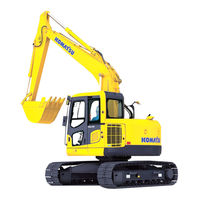
PC200-8M0 Shop Manual
946 pages
Galeo PC138US-8 Shop Manual
1201 pages
PC210-8 Shop Manual
1043 pages
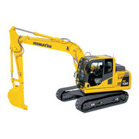
PC130-8 Shop Manual

1035 pages
ecot3 PC300LC-8 Shop Manual
458 pages
PC210-10 Operation & Maintenance Manual
1117 pages
Galeo PC800-8 Shop Manual
1435 pages
PC88MR-10 Shop Manual
711 pages
PC200-6 Shop Manual
381 pages
PC300LC-8 Operation & Maintenance Manual

502 pages
PC350LC-8 Operation & Maintenance Manual
375 pages
PC138USLC Operation & Maintenance Manual
40 pages
PC200-7 Operator’s Maintenance Manual
504 pages
PC2000-8 Operation & Maintenance Manual

51 pages
PC200 -8 Shop Manual
475 pages
PC45MR-5 Operation And Maintenance Manual
9 pages
PC300-7 Brochure
248 pages
PC05-6 Shop Manual
343 pages
PC1250-7 Operation & Maintenance Manual
380 pages
PC30MR-5 Operation & Maintenance Manual
Models
Document Type
1
15027

Operation & Maintenance Manual
3
30258
Operation & Maintenance Manual
35001
Shop Manual
5
500001
Shop Manual
50001
Operation & Maintenance Manual • Shop Manual • Field Assembly Instructions
5001
Shop Manual • Field Assembly Instructions
6
65001
Shop Manual
7
70001
Shop Manual
72642
Operation & Maintenance Manual
A
A00001
Operation & Maintenance Manual • Shop Manual
A10001
Operation & Maintenance Manual • Operation & Maintenance Manual • Shop Manual • Operation & Maintenance Manual
A20001
Shop Manual • Shop Manual
A20601
Operation & Maintenance Manual
A22001
Operation & Maintenance Manual • Shop Manual
A27001
Shop Manual
A29501
Shop Manual
A30001
Operation & Maintenance Manual
A30401
Shop Manual
A31001
Operation & Maintenance Manual
A32001
Operation & Maintenance Manual
A35001
Shop Manual • Shop Manual
A38001
Operation & Maintenance Manual
A40001
Shop Manual • Shop Manual • Operation & Maintenance Manual
A52001
Operation & Maintenance Manual
A86001
Operation & Maintenance Manual
A87001
Operation & Maintenance Manual • Shop Manual • Shop Manual
A88001
Operation & Maintenance Manual
A90001
Operation & Maintenance Manual • Shop Manual
A90301
Shop Manual
B
Breathesafe WA900-3EO
Installation Overview
D
D85EX_15R — D85PX-15R
Dimensions
E
ecot3 PC160LC-8
Shop Manual
ecot3 PC300-8
Shop Manual
ecot3 PC300LC-8
Shop Manual
ecot3 PC350-8
Shop Manual
ecot3 PC350LC-8
Shop Manual
F
F30791
Shop Manual
F31103
Shop Manual
G
GALEO BR550JG-1
Operation & Maintenance Manual
Galeo D61EX-15
Operation & Maintenance Manual
Galeo D61PX-15
Operation & Maintenance Manual
Galeo D85EX-15R
Dimensions
Galeo D85PX-15R
Dimensions
Galeo PC1250-7 Backhoe
Brochure • Operation & Maintenance Manual
Galeo PC138US-8
Brochure • Operation & Maintenance Manual • Shop Manual
Galeo PC138USLC-8
Operation & Maintenance Manual • Shop Manual
Galeo PC14R-2
Operation & Maintenance Manual
Galeo PC270-7
Brochure
Galeo PC27MR-2
Operation & Maintence Manual
Galeo PC35MR-2
Operation & Maintence Manual
Galeo PC400-7
Brochure
Galeo PC400-8R
Brochure
Galeo PC400LC-7
Brochure
Galeo PC400LC-8R
Brochure
Galeo PC800-8
Shop Manual
Galeo PC800LC-8
Shop Manual • Operation & Maintenance Manual
Galeo PC800SE-8
Shop Manual
Galeo PC850-8
Shop Manual
Galeo PC850SE-8
Shop Manual
H
HB205 -1
Shop Manual
HB215LC-1
Shop Manual
HB215LC-2
Shop Manual
HB215LC-3
Operation & Maintenance Manual
HB365LC-3
Operation & Maintenance Manual
HB365NLC-3
Operation & Maintenance Manual
K
K30001
Operation & Maintenance Manual
K35001
Operation & Maintenance Manual
K50001
Operation & Maintenance Manual
K50114
Operation & Maintenance Manual
K50304
Operation & Maintenance Manual
K51095
Operation & Maintenance Manual
K64001
Operation & Maintenance Manual
P
PC05-6
Shop Manual • Shop Manual
PC07-1
Shop Manual • Shop Manual
PC09-1
Shop Manual
PC10-6
Shop Manual • Shop Manual
PC110R-1
Operation & Maintenance Manual
PC118MR-8
Operation And Maintenance Manual
PC1250 —
Brochure • Brochure
PC1250 -8
Shop Manual
PC1250-11
Original Instructions Manual
PC1250-8 Loading Shovel
Brochure
PC1250-8R —
Brochure
PC1250LC -8
Shop Manual
PC1250SP-11
Original Instructions Manual
PC1250SP-7
Operation & Maintenance Manual
PC1250SP-8 Backhoe
Brochure • Shop Manual
PC1250SP-8R —
Brochure
PC128US-8
Shop Manual
PC12R-8
Operation & Maintenance Manual
PC12R-8 HS
Operation & Maintenance Manual
PC130-6K 2001
Operation & Maintenance Manual
PC130-6K 2002
Operation & Maintenance Manual
PC130-6K 2003
Operation & Maintenance Manual
PC130-6K 2004
Operation & Maintenance Manual
PC130-7
Shop Manual • Operation & Maintenance Manual
PC130-8
Brochure • Shop Manual
PC138US
Operation & Maintenance Manual
PC138US-11
Operation & Maintenance Manual
PC138USLC
Operation & Maintenance Manual
PC138USLC-11
Shop Manual
PC14R-3
Operation & Maintence Manual
PC14R-3HS
Operation & Maintence Manual
PC15-2
Shop Manual • Shop Manual
PC150LGP-6K 2001
Operation & Maintenance Manual
PC150LGP-6K 2002
Operation & Maintenance Manual
PC150LGP-6K 2003
Operation & Maintenance Manual
PC150LGP-6K 2004
Operation & Maintenance Manual
PC15MRX-1
Operation And Maintenance Manual
PC15R-8
Operation & Maintenance Manual
PC15R-8 HS
Operation & Maintenance Manual
PC160LC-8
Brochure • Operation & Maintenance Manual
PC16R-3
Operation & Maintenance Manual
PC16R-3HS
Operation & Maintenance Manual
PC170LC-11
Shop Manual
PC18MR-3
Brochure • Operation & Maintenance Manual
PC190LC-8
Operation & Maintenance Manual
PC190NLC-8
Operation & Maintenance Manual
PC200 -8
Shop Manual
PC200- 300001
Shop Manual
PC200-6
Shop Manual
PC200-7
Operator’s Maintenance Manual
PC200-8
Brochure
PC200-8M0
Shop Manual
PC2000-8 BACKHOE
Brochure • Operation & Maintenance Manual
PC2000-8 LOADING SHOVEL
Brochure
PC200LC- 300001
Shop Manual
PC200LC-6
Shop Manual
PC200LC-7
Operator’s Maintenance Manual
PC200LC-8
Brochure • Shop Manual • Shop Manual
PC200LC-8M0
Shop Manual
PC200LL-8
Shop Manual
PC20R-8
Operation & Maintenance Manual • Shop Manual
PC210
Operation & Maintenance Manual
PC210-10 DEMOLITION BASE SPEC.
Operation & Maintenance Manual
PC210-11
Operation & Maintenance Manual
PC210-8
Shop Manual • Operation & Maintenance Manual
PC210LC-10 DEMOLITION BASE SPEC.
Operation & Maintenance Manual • Operation & Maintenance Manual
PC210LC-11
Operation & Maintenance Manual • Shop Manual
PC210LC-6
Shop Manual
PC210LC-6K
Operation & Maintenance Manual
PC210LC-8
Shop Manual • Operation & Maintenance Manual
PC210LCI-11
Shop Manual
PC210LL-10
Operation & Maintenance Manual
PC210NLC-11
Operation & Maintenance Manual
PC210NLC-8
Shop Manual • Operation & Maintenance Manual
PC220 -8
Shop Manual
PC220- 70001
Shop Manual
PC220-7 —
Brochure • Operator’s Maintenance Manual
PC220-8
Brochure
PC220-8M0
Shop Manual
PC220LC- 70001
Shop Manual
PC220LC-6
Shop Manual
PC220LC-7 —
Brochure • Operator’s Maintenance Manual
PC220LC-8
Brochure • Shop Manual
PC220LC-8M0
Shop Manual
PC220LL-8
Shop Manual
PC228US-3EO
Brochure
PC228USLC-3EO
Brochure
PC22MR-3
Operation & Maintenance Manual
PC230NHD-11
Operation & Maintenance Manual
PC230NHD-8
Shop Manual • Operation & Maintenance Manual
PC238USLC-11
Shop Manual
PC240LC
Operation & Maintenance Manual
PC240LC-10
Operation & Maintenance Manual • Shop Manual
PC240LC-11
Operation & Maintenance Manual • Shop Manual
PC240LC-8
Shop Manual • Operation & Maintenance Manual
PC240LL-10
Operation & Maintenance Manual
PC240NLC-6K
Operation & Maintenance Manual
PC240NLC-8
Shop Manual • Operation & Maintenance Manual
PC250LC-6
Shop Manual
PC270-8
Brochure
PC270LC-8
Brochure
PC270LL-7L
Operation & Maintenance Manual
PC27R-8
Operation & Maintenance Manual • Shop Manual
PC290LC-10
Operation & Maintenance Manual
PC290LC-11
Operation & Maintenance Manual • Operation & Maintenance Manual • Shop Manual
PC290LC-6K
Operation & Maintenance Manual
PC290LL-11
Shop Manual
PC290NLC-11
Operation & Maintenance Manual
PC290NLC-6K
Operation & Maintenance Manual
PC300-7 —
Brochure
PC300-8
Brochure • Operation & Maintenance Manual
PC300HD-8
Operation & Maintenance Manual • Shop Manual
PC300LC-7 —
Brochure
PC300LC-8
Brochure • Operation & Maintenance Manual • Operation & Maintenance Manual • Shop Manual
PC308USLC-3E0
Operation & Maintenance Manual
PC30MR-5
Operation & Maintenance Manual
PC350-7
Brochure
PC350-8
Brochure • Operation & Maintenance Manual
PC350HD-8
Operation & Maintenance Manual • Shop Manual
PC350LC-7
Brochure
PC350LC-8
Brochure • Operation & Maintenance Manual • Operation & Maintenance Manual • Operation & Maintenance Manual • Shop Manual
PC350NLC-8
Operation & Maintenance Manual
PC35MR-5
Operation & Maintenance Manual
PC360LC-10
Operation & Maintenance Manual
PC360LC-11
Operation & Maintenance Manual • Operation & Maintenance Manual • Shop Manual
PC360LCi-11
Operation & Maintenance Manual
PC360NLC-11
Operation & Maintenance Manual
PC390LC-10
Operation & Maintenance Manual
PC390LC-11
Operation & Maintenance Manual • Shop Manual
PC390LCi-11
Operation & Maintenance Manual
PC400
Operation & Maintenance Manual
PC400-5 MIGHTY
Operation & Maintenance Manual
PC400-8
Brochure • Shop Manual
PC4000
Assembly Procedure • Manual
PC400HD-5
Operation & Maintenance Manual
PC400LC-5 MIGHTY
Operation & Maintenance Manual
PC400LC-8
Brochure • Operation & Maintenance Manual • Shop Manual
PC450-7
Brochure
PC450-8
Brochure • Shop Manual • Operation & Maintenance Manual
PC450-8R
Brochure
PC450LC-7
Brochure
PC450LC-8
Brochure • Operation & Maintenance Manual • Shop Manual • Operation & Maintenance Manual
PC450LC-8R
Brochure
PC45MR-30403
Operation And Maintenance Manual
PC45MR-5
Operation And Maintenance Manual
PC490-11
Installation And Instruction Manual
PC490LC
Installation And Instruction Manual
PC490LC-10
Shop Manual • Operation & Maintenance Manual
PC490LC-11
Operation & Maintenance Manual
PC500LC-10R
Shop Manual
PC5500-6
Operation & Maintenance Manual
PC55MR-20398
Operation And Maintenance Manual
PC55MR-5
Operation And Maintenance Manual
PC600 —
Brochure
PC600 -8E0
Shop Manual
PC600-6
Operation And Maintenance Manual
PC600-7 Backhoe
Brochure
PC600-7 Loading Shovel
Brochure
PC600-8 BACKHOE
Brochure
PC600-8 LOADING SHOVEL
Brochure
PC600-8R BACKHOE
Brochure
PC600-8R LOADING SHOVEL
Brochure
PC600LC-6
Operation And Maintenance Manual
PC600LC-7 Backhoe
Brochure
PC600LC-7 Loading Shovel
Brochure
PC600LC-8 BACKHOE
Brochure
PC600LC-8E0
Shop Manual
PC600LC-8LOADING SHOVEL
Brochure
PC600LC-8R BACKHOE
Brochure
PC600LC-8R LOADING SHOVEL
Brochure
PC650 -8E0
Shop Manual
PC650LC-8E0
Shop Manual
PC700LC-11
Operation & Maintenance Manual
PC700LC-8E0
Shop Manual
PC750
Brochure
PC750-7 BACKHOE
Brochure • Shop Manual
PC750-7 LOADING SHOVEL
Brochure
PC750LC-7
Shop Manual
PC750SE-7 BACKHOE
Brochure • Shop Manual
PC78US-10
Shop Manual
PC78US-6
Operation & Maintenance Manual
PC800 -8E0
Shop Manual
PC800 BACKHOE
Brochure • Brochure
PC800- 65001
Shop Manual
PC800-7
Shop Manual
PC800-8 BACKHOE
Brochure
PC800-8 LOADING SHOVEL
Brochure • Brochure • Operation & Maintenance Manual
PC800-8R —
Brochure
PC800LC- 65001
Shop Manual
PC800LC-8E0
Shop Manual
PC800SE- 65001
Shop Manual
PC800SE-7
Shop Manual
PC800SE-8 BACKHOE
Brochure
PC800SE-8E0
Shop Manual
PC800SE-8R BACKHOE
Brochure
PC80MR-5E0
Operation & Maintenance Manual
PC850 -8E0
Shop Manual
PC850- 65001
Shop Manual
PC850-8 BACKHOE
Brochure
PC850SE- 65001
Shop Manual
PC850SE-8 BACKHOE
Brochure
PC850SE-8E0
Shop Manual
PC88MR-10
Operation & Maintenance Manual • Shop Manual
PW118MR-11
Operation & Maintenance Manual
PW130ES-6K
Operation & Maintenance Manual
PW160-7H
Operation & Maintenance Manual
PW160-7K Series
Operation And Maintenance Manual
PW160-7K-K40001
Operation And Maintenance Manual
PW180-7E0
Operation & Maintenance Manual
PW98MR-10
Operation & Maintenance Manual
W
WA270-3H
Operation & Maintenance Manual
WA800-1
Operation & Maintenance Manual
WA800-10001
Operation & Maintenance Manual
WA900-3E0
Brochure • Operation & Maintenance Manual • Shop Manual
Курсы машинистов ДСМ (Komatsu…)
Back to top
Для машинистов
Инструкции для машинистов ДСМ
Инструкция, Экскаватор Komatsu PC1800.
Инструкция (мануал) Карьерный экскаватор Komatsu PC1800.
Ссылка — скачать.
Компания:
Komatsu
Тип инструкции:
Для машинистов
- Подробнее о Инструкция, Экскаватор Komatsu PC1800.
Инструкция, Экскаватор Komatsu PC1800.
Инструкция (мануал) Карьерный экскаватор Komatsu PC1800.
Компания:
Komatsu
Тип инструкции:
Для машинистов
- Подробнее о Инструкция, Экскаватор Komatsu PC1800.
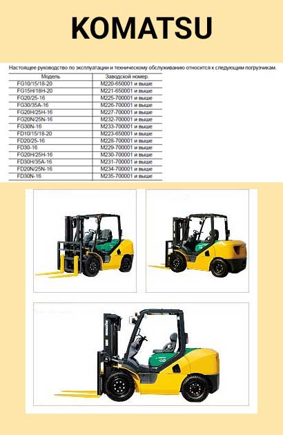
Вилочные погрузчики Komatsu
Вилочные погрузчики Komatsu
Ссылка — скачать.
Компания:
Komatsu
Тип инструкции:
Для машинистов
- Подробнее о Вилочные погрузчики Komatsu
Грейдер. Terex TG190.
Грейдер Terex TG 190.
Компания:
Terex
Тип инструкции:
Для машинистов
- Подробнее о Грейдер. Terex TG190.
Руководство для оператора. Экскаватор Hitachi ZX225US
Руководство для оператора. Экскаватор Hitachi ZX225US.
Компания:
Hitachi
Тип инструкции:
Для машинистов
- Подробнее о Руководство для оператора. Экскаватор Hitachi ZX225US
Страницы
- 1
- 2
- 3
- 4
- 5
- 6
- следующая ›
- последняя »
![]()
Back to top
Руководство по эксплуатации PW170ES-6K
Руководство по эксплуатации WA470-3 Magnum
Руководство по эксплуатации WA470-3 China
Руководство по эксплуатации WA470-3
Руководство по эксплуатации WA380-3
Руководство по эксплуатации WA380-3 (KCCM)
Руководство по эксплуатации PC400(LC)-7
Руководство по эксплуатации PC200(LC)-7 Galeo
Руководство по эксплуатации 220LC-7
Руководство по эксплуатации WA320-3(SM)
Руководство по эксплуатации WB97S-5
Руководство по эксплуатации WB93S-5
Руководство по эксплуатации WB93R-5
Руководство по эксплуатации WA470-3 KCCM
Руководство по эксплуатации WA470-3
Руководство по эксплуатации WA470-3
Руководство по эксплуатации PW160-7H
Руководство по эксплуатации PC60-7
Руководство по эксплуатации PC400(LC)-7
Руководство по эксплуатации PC400(LC)
Руководство по эксплуатации PC40(50)MR-2
Руководство по эксплуатации PC35(45)R-8
Руководство по эксплуатации PC300-7
Руководство по эксплуатации PC300(350)(LC)-7
Руководство по эксплуатации PC270-7
Руководство по эксплуатации PC27(35)MR-2
Руководство по эксплуатации [OM Eng]WA270-3H
Руководство по эксплуатации WA20(30)(40)(50)
Руководство по эксплуатации PW160-7K
Руководство по эксплуатации PW130ES-6K
Руководство по эксплуатации PC30(35)MR-2
Руководство по эксплуатации PW180-7E
Руководство по эксплуатации WB97S-5
Руководство по эксплуатации WB97R-5
Руководство по эксплуатации D355A-3
Руководство по эксплуатации Komatsu WA470-5
Руководство по эксплуатации Komatsu PC20(30)-6 (SEAM02250602)
Руководство по эксплуатации Komatsu PC210-240
ОТПРАВИТЬ ЗАЯВКУ:
Нажимая кнопку «ОТПРАВИТЬ ЗАЯВКУ», Вы соглашаетесь на обработку Ваших данных Подробнее
НАШИ ПРЕИМУЩЕСТВА
![]()
Выезд
к заказчику
![]()
Собственная
ремзона
![]()
Дополнительное
оборудование
![]()
Гарантийное
постгарантийное
сезонное ТО
![]()
Запчасти
в наличии
![]()
Шиномонтаж
МЫ РЕМОНТИРУЕМ:


KOMATSU (PС-200-220-7):
НА ЭТОЙ СТРАНИЦЕ РАЗРЕШЕН ТОЛЬКО ПРОСМОТР, ДЛЯ ТОГО ЧТОБЫ СКАЧАТЬ ИНСТРУКЦИЮ ОБРАЩАЙТЕСЬ К НАМ ПИШИТЕ НА ПОЧТУ AK.ZXZXZX@RO.RU
Смотрите также каталог для запчастей.
KOMATSU (PC-220-7)

- Manuals
- Brands
- Komatsu Manuals
- Excavators
- PC200-8M0
- Shop manual
-
Contents
-
Table of Contents
-
Troubleshooting
-
Bookmarks
Quick Links
HYDRAULIC
EXCAVATOR
PC200
PC200LC
PC220
PC220LC
SERIAL NUMBERS
SEN06109-03
-8M0
-8M0
-8M0
-8M0
PC200-
400001
PC200LC- 400001
PC220-
100001
PC220LC- 100001
and up
Chapters
-
Hydraulic Excavator
3 -
Table of Contents
8 -
Pc200-8M0 Pc200Lc-8M0 Pc220-8M0 Pc220Lc-8M0
17 -
Pc200-8M0 Pc200Lc-8M0 Pc220-8M0 Pc220Lc-8M0
67 -
Pc200-8M0 Pc200Lc-8M0 Pc220-8M0 Pc220Lc-8M0
85 -
Pc200-8M0 Pc200Lc-8M0 Pc220-8M0 Pc220Lc-8M0
99 -
Pc200-8M0 Pc200Lc-8M0 Pc220-8M0 Pc220Lc-8M0
113 -
Pc200-8M0 Pc200Lc-8M0 Pc220-8M0 Pc220Lc-8M0
199 -
Pc200-8M0 Pc200Lc-8M0 Pc220-8M0 Pc220Lc-8M0
267 -
Pc200-8M0 Pc200Lc-8M0 Pc220-8M0 Pc220Lc-8M0
353 -
Pc200-8M0 Pc200Lc-8M0 Pc220-8M0 Pc220Lc-8M0
473 -
Hydraulic Excavator
505 -
Hydraulic Excavator
571 -
Hydraulic Excavator
621
Troubleshooting
-
Tools for testing, adjusting, and troubleshooting
355 -
Preparation work for troubleshooting of electrical system
475 -
Troubleshooting
493 -
Troubleshooting
506 -
Symptom and troubleshooting numbers
507 -
Sequence of events in troubleshooting
508 -
Checks before troubleshooting
510 -
Classification and procedures for troubleshooting
512 -
Symptom and troubleshooting numbers
514 -
Information in troubleshooting table
516 -
Troubleshooting method for open circuit in wiring harness of pressure sensor system
567 -
Troubleshooting by failure code, Part
571 -
Troubleshooting by failure code, Part
621 -
Troubleshooting by failure code, Part
677 -
Troubleshooting by failure code, Part
725 -
Troubleshooting by failure code, Part
773 -
Information contained in troubleshooting table
828 -
Information in troubleshooting table
888 -
Method of using troubleshooting chart
924 -
Procedure for testing and troubleshooting
1178 -
Troubleshooting chart 2
1196 -
Information in troubleshooting table
1200 -
Troubleshooting for power supply and CAN communication system (Air conditioner does not operate)
1216 -
Troubleshooting for compressor and refrigerant system (Air is not cooled)
1218 -
Troubleshooting for blower motor system (No air comes out or air flow is abnormal)
1221 -
Troubleshooting for FRESH/RECIRC air changeover
1223 -
Troubleshooting with gauge pressure
1225
Related Manuals for Komatsu PC200-8M0
Summary of Contents for Komatsu PC200-8M0
-
Page 1
SEN06109-03 HYDRAULIC PC200 -8M0 EXCAVATOR PC200LC -8M0 PC220 -8M0 PC220LC -8M0 PC200- 400001 PC200LC- 400001 SERIAL NUMBERS and up PC220- 100001 PC220LC- 100001… -
Page 3: Table Of Contents
SEN06111-03 HYDRAULIC EXCAVATOR 1SHOP MANUAL PC200-8M0 PC200LC-8M0 PC220-8M0 PC220LC-8M0 Machine model Serial number PC200-8M0 400001 and up PC200LC-8M0 400001 and up PC220-8M0 100001 and up PC220LC-8M0 100001 and up 00 Index and foreword 100 Index Composition of shop manual …………………….. 2 Table of contents ………………………..
-
Page 4: Composition Of Shop Manual
100 Index SEN06111-03 Composition of shop manual Composition of shop manual The contents of this shop manual are shown together with Form No. in a list. Note 1: Always keep the latest version of this manual in accordance with this list and utilize accordingly. The marks shown to the right of Form No.
-
Page 5
100 Index Composition of shop manual SEN06111-03 40 Troubleshooting SEN06130-01 100 Failure code table and fuse locations SEN06131-00 200 General Information on troubleshooting SEN06132-01 301 Troubleshooting by failure code, Part 1 SEN06133-00 302 Troubleshooting by failure code, Part 2 SEN06134-00 303 Troubleshooting by failure code, Part 3 SEN06135-00 304 Troubleshooting by failure code, Part 4… -
Page 6: Table Of Contents
100 Index SEN06111-03 Table of contents Table of contents 00 Index and foreword 100 Index SEN06111-03 Composition of shop manual ………………..Table of contents……………………200 Foreword and general information SEN06112-00 Foreword, safety and general information …………….How to read the shop manual………………..Explanation of terms for maintenance standard …………..
-
Page 7
100 Index Table of contents SEN06111-03 Center swivel joint ……………………10 Travel motor……………………..12 PPC valve……………………..22 Valve control ……………………..42 Solenoid valve ……………………. 44 PPC accumulator……………………46 Return oil filter ……………………. 47 Attachment circuit selector valve ………………… 48 Hydraulic cylinder ……………………50 500 Work equipment SEN06122-00 Work equipment …………………… -
Page 8: Table Of Contents
100 Index SEN06111-03 Table of contents Releasing remaining pressure from hydraulic circuit …………… 54 Testing oil leakage ……………………55 Bleeding air from each part…………………. 58 Testing cab tipping stopper …………………. 60 Adjusting mirrors……………………61 Installation and adjustment of mirrors ………………62 Angle adjustment of rear view camera ………………
-
Page 9
100 Index Table of contents SEN06111-03 Failure code [CA132] Throttle Sensor Low Error…………..26 Failure code [CA144] Coolant Temp Sens High Error …………. 28 Failure code [CA145] Coolant Temp Sens Low Error ………….. 30 Failure code [CA153] Chg Air Temp Sensor High Error …………32 Failure code [CA154] Chg Air Temp Sensor Low Error ………… -
Page 10
100 Index SEN06111-03 Table of contents Failure code [DAF0MC] Monitor Error ………………27 Failure code [DAF8KB] Camera Power Supply Short Circuit ……….28 Failure code [DAF9KQ] Model Selection Abnormality …………. 30 Failure code [DAFGMC] GPS Module Error …………….31 Failure code [DAFQKR] CAN2 Discon ………………32 Failure code [DAZ9KQ] A/C Model Selection Abnormality ………… -
Page 11
100 Index Table of contents SEN06111-03 Failure code [DY2EKB] Wiper Drive (Rev) Short …………..48 400 Troubleshooting of electrical system (E-mode) SEN06138-00 Fuse locations ……………………. Information contained in troubleshooting table ……………. E-1 Engine does not start (Engine does not crank) …………..E-2 Preheater does not operate ……………….. -
Page 12
100 Index SEN06111-03 Table of contents H-14 In combined operation of work equipment, equipment having heavier load moves slower…………24 H-15 In combined operation of swing and boom RAISE, boom rising speed is low ….25 H-16 Travel speed drops largely in combined operation of swing and travel ……26 H-17 Machine does not travel straight ……………… -
Page 13
100 Index Table of contents SEN06111-03 Disassembly and assembly of swing motor and swing machinery assembly……24 Removal and installation of swing circle assembly…………..34 400 Undercarriage and frame SEN06145-00 Disassembly and assembly of carrier roller assembly…………. Disassembly and assembly of track roller assembly …………… Removal and installation of idler and idler cushion assembly ………. -
Page 14
100 Index SEN06111-03 Table of contents Testing (dual) pressure switch for refrigerant …………….36 Testing relays ……………………..37 Troubleshooting chart 1………………….. 38 Troubleshooting chart 2………………….. 40 Information in troubleshooting table ……………….. 42 Failure code list related to air conditioner………………43 Failure code [879AKA] A/C Inner sensor Open Circuit …………… -
Page 15
100 Index Table of contents SEN06111-03 PC200, 200LC, 220, 220LC-8M0 00-100… -
Page 16
SEN06111-03 PC200-8M0, PC200LC-8M0, PC220-8M0, PC220LC-8M0 Hydraulic excavator Form No. SEN06111-03 © 2014 KOMATSU All Rights Reserved Printed in Japan 09-14 (01) 00-100… -
Page 17
SEN06112-00 HYDRAULIC EXCAVATOR 1SHOP MANUAL PC200-8M0 PC200LC-8M0 PC220-8M0 PC220LC-8M0 Machine model Serial number PC200-8M0 400001 and up PC200LC-8M0 400001 and up PC220-8M0 100001 and up PC220LC-8M0 100001 and up 00 Index and foreword 200 Foreword and general information Foreword, safety and general information …………………. 2 How to read the shop manual ……………………. -
Page 18: Foreword, Safety And General Information
Appropriate servicing and repair are extremely important to ensure safe operation of the machine. The shop manual describes the effective and safe servicing and repair methods recommended by Komatsu. Some of these methods require the use of the special tools designed by Komatsu for the specific pur- pose.
-
Page 19
200 Foreword and general information Foreword, safety and general information SEN06112-00 When performing the disassembling or assem- When removing the part which is under internal bling work, support the machine securely with pressure or reaction force of the spring, always blocks, jacks, or stands before starting the leave two bolts in diagonal positions. -
Page 20
200 Foreword and general information SEN06112-00 Foreword, safety and general information Precautions for slinging work and making sig- nals Only one appointed worker must make signals and co-worker must communicate with each other frequently. The appointed signaler must make specified signals clearly at the place where the signaler is well seen from the opera- tor's seat and where the signaler can see the working condition easily. -
Page 21
200 Foreword and general information Foreword, safety and general information SEN06112-00 When lifting down a load, stop it temporar- After finishing the work, stop the hoist at the ily at 30 cm above the floor, and then specified position and raise the hook to at least lower it slowly. -
Page 22
200 Foreword and general information SEN06112-00 Foreword, safety and general information When loosening the nuts fixing air conditioner hoses and tubes, be sure to use two wrenches; use one wrench to fix and use the other one to loosen the nut. Connection When installing the hose for the air conditioner circuit, take care not to allow invasion of dirt,… -
Page 23
200 Foreword and general information Foreword, safety and general information SEN06112-00 Fire prevention When performing grinding or welding work on the machine, move any flammable Action if fire occurs materials to a safe place before starting. Turn the starting switch to the OFF position to shutdown the engine. -
Page 24
T h i s m a c h i n e i s e q u i p p e d w i t h K D P F (Komatsu Diesel Particulate Filter). KDPF is a system for purifying soot in exhaust gas. -
Page 25: How To Read The Shop Manual
This section gives hydraulic circuit diagrams and electrical circuit diagrams. Revision and distribution Any additions, revisions, or other change of notices will be sent to KOMATSU distributors. Get the most up- to-date information before you start any work. Filing method File by the brochures in the correct order of the form number printed in the shop manual composition table.
-
Page 26
200 Foreword and general information SEN06112-00 How to read the shop manual Revised edition mark When a manual is revised, the ones and tens digits of the form number of each brochure is increased by 1. (Example: 00, 01, 02 …) Revisions Revised brochures are shown in the shop manual composition table. -
Page 27: Explanation Of Terms For Maintenance Standard
200 Foreword and general information Explanation of terms for maintenance standard SEN06112-00 Explanation of terms for maintenance standard The chapter of maintenance standard shows judgement criteria to determine the products to be replaced or to be reused. The judgement criteria are described by using the following terms. Standard dimension and tolerance When some parts are repaired, the value of performance/function is set to the standard…
-
Page 28
200 Foreword and general information SEN06112-00 Explanation of terms for maintenance standard Repair limit and allowable value or allowable dimension The dimensions of parts change because of the wear or deformation while they are used. When the dimension changes exceeding cer- tain value, the parts can not be used any lon- ger. -
Page 29: Handling Equipment Of Fuel System Devices
If any dirt or dust sticks the parts of the fuel system, clean it off thoroughly with clean fuel. Precautions for replacing fuel filter cartridge Be sure to use the Komatsu genuine fuel filter cartridge. The common rail fuel injection system (CRI)
-
Page 30: Handling Of Intake System Parts
200 Foreword and general information SEN06112-00 Handling of intake system parts Handling of intake system parts The Komatsu Variable Geometry Turbocharger (KVGT) consists of more precise parts (vari- able mechanism) than the parts used in the conventional turbocharger. If foreign material enters this system, it may cause a failure.
-
Page 31: Handling Of Hydraulic Equipment
200 Foreword and general information Handling of hydraulic equipment SEN06112-00 Handling of hydraulic equipment With the increase in pressure and precision of the hydraulic components, the most common cause of a failure is dirt (foreign material) in the hydraulic circuit. Therefore, the special care must be taken when adding hydraulic oil,or wh en di s as s em bl in g or a s se mb li ng th e hydraulic components.
-
Page 32
200 Foreword and general information SEN06112-00 Handling of hydraulic equipment Flushing operations After disassembling the equipment or when changing the hydraulic oil with new one, flush the system to remove the contaminant and sludge left in the hydraulic circuit as well as the oil which includes them. -
Page 33: Method Of Disconnecting And Connectingof Push-Pull Type Coupler
200 Foreword and general information Method of disconnecting and connecting of push-pull type SEN06112-00 Method of disconnecting and connecting of push-pull type coupler Loosen the oil filler cap of the hydraulic tank slowly to release the remaining pressure in the hydraulic tank.
-
Page 34
200 Foreword and general information SEN06112-00 Method of disconnecting and connecting of push-pull type Type 2 Disconnection Connection While holding the fitting, push body (7) in While holding the fitting, push body (7) in straight until sliding prevention ring (6) hits straight until sliding prevention ring (6) hits contact surface (a) at the hexagonal part on contact surface (a) at the hexagonal part on… -
Page 35
200 Foreword and general information Method of disconnecting and connecting of push-pull type SEN06112-00 Type 3 Disconnection Connection While holding the fitting, push body (9) in While holding the fitting, push body (9) in straight until sliding prevention ring (8) hits straight until sliding prevention ring (8) hits contact surface (b) at the hexagonal portion on contact surface (a) at the hexagonal portion on… -
Page 36: Handling Of Electrical Equipment
200 Foreword and general information SEN06112-00 Handling of electrical equipment Handling of electrical equipment To maintain the performance of the machine over a long period, and to prevent failures or troubles before they occur, correct “operation”, “maintenance and inspection” “troubleshooting”, and “repairs” must be performed.
-
Page 37
200 Foreword and general information Handling of electrical equipment SEN06112-00 Oil, mud or dirt stuck to connector If any oil or grease is stuck to the connector and an oil film is formed on the mating surface of the male and female pins, the oil prevents electricity from passing through, resulting in defective contact. -
Page 38
200 Foreword and general information SEN06112-00 Handling of electrical equipment a If the machine is left disassembled for a long time, it is particularly easy for improper contact to occur, so always cover the connector. When removing from clips Both of the connector and clip have stop- pers, which are engaged with each other when the connector is connected. -
Page 39
200 Foreword and general information Handling of electrical equipment SEN06112-00 For connectors fitted with the boot, correct Connection any extrusion of the boot. In addition, if the Push in female connector (2) horizontally until wiring harness or the clamp is out of the the lock clicks. -
Page 40
200 Foreword and general information SEN06112-00 Handling of electrical equipment Dry the inside of the connector with a dryer. Handling of connectors used on engine If water gets inside the connector, use a dryer Slide lock type (Type 1) (FRAMATOME-3, FRAM- to dry the connector. -
Page 41
200 Foreword and general information Handling of electrical equipment SEN06112-00 While pressing lock (L2), pull out connector Connection (1). Insert the connector securely until a click is heard. Push lock type (1) (BOSCH-3) Disconnection While pressing lock (C), pull out connector (3) in the direction of the arrow. -
Page 42
200 Foreword and general information SEN06112-00 Handling of electrical equipment Connection Example) Injection pressure control valve of Insert the connector securely until a click is supply pump: PCV (SUMITOMO-2) heard. Push lock type (2) (SUMITOMO-4) Disconnection While pressing lock (C), pull out connector (4) in the direction of the arrow. -
Page 43
200 Foreword and general information Handling of electrical equipment SEN06112-00 Turn-housing type (Round green connector) Handling controller (CANNON-4) The electronic circuits for control including the microcomputers are assembled in the control- Disconnection ler. These electronic circuits in the controller Turn housing (H1) in the direction of the arrow. a Unlock the connector by turning housing must be handled with care as they control the machine. -
Page 44
200 Foreword and general information SEN06112-00 Handling of electrical equipment Precautions for troubleshooting electrical cir- cuits Be sure to turn the starting switch to the “OFF” position before disconnecting or connecting the connectors. Before performing troubleshooting, check all the related connectors for loose connection. a Check the related connectors for their per- formance by disconnecting and connect- ing them several times. -
Page 45: How To Read Electric Wire Code
200 Foreword and general information How to read electric wire code SEN06112-00 How to read electric wire code In the electrical circuit diagram, material, thickness and color of each electric wire are indicated by sym- bols. The wire code is helpful in understanding the electrical circuit diagram. Example) AEX 0.85 L: Indicates blue, heat-resistant, low-voltage wire for automobile, having nominal No.
-
Page 46
200 Foreword and general information SEN06112-00 How to read electric wire code Dimension (Table 2) Nominal No. 0.5f (0.5) 0.75f (0.85) 1.25f (1.25) Number of strands/Diam- 20/0.18 7/0.32 30/0.18 11/0.32 50/0.18 16/0.32 37/0.26 26/0.32 58/0.26 41/0.32 65/0.32 eter of strand Conductor Cross- sectional… -
Page 47
200 Foreword and general information How to read electric wire code SEN06112-00 Color codes table (Table 3) Color Code Color of wire Color Code Color of wire Black Light green & White Brown Light green & Yellow Brown & Black Blue &… -
Page 48: Precautions When Performing Operation
200 Foreword and general information SEN06112-00 Precautions when performing operation Precautions when performing operation When performing “removal or installation” and “disassembly or assembly” of the components, observe the following general cautions. Precautions for removal work If the coolant contains antifreeze, dispose of it correctly as chemicals. Do not drain the coolant to the sewage rashly.
-
Page 49
200 Foreword and general information Precautions when performing operation SEN06112-00 If the part is not under hydraulic pressure, the following corks can be used. Dimensions Nominal No. Part Number 07049-00608 07049-00811 07049-01012 07049-01215 07049-01418 11.5 07049-01620 13.5 07049-01822 07049-02025 07049-02228 18.5 07049-02430 07049-02734… -
Page 50
When the coolant is drained, tighten the drain valve securely, then refill the coolant reservoir with the coolant Komatsu recommends to the specified level. Start the engine to circulate the coolant in the pip- ing, and add the coolant to the specified level again. -
Page 51: Practical Use Of Komtrax
200 Foreword and general information Practical use of KOMTRAX SEN06112-00 Practical use of KOMTRAX KOMTRAX system transmits various machine information by use of the radio communication and KOMTRAX operator can refer this information in the office and provide various services to the customers. When KOMTRAX is installed on the machine, the machine information can be checked through the KOMTRAX system and the testing and troubleshooting can be performed efficiently.
-
Page 52: Standard Tightening Torque Table
200 Foreword and general information SEN06112-00 Standard tightening torque table Standard tightening torque table Table of tightening torque for bolts and nuts Unless otherwise specified, tighten the metric bolts and nuts to the torque shown in the table below. The following table applies to the bolts in Fig. A. Thread Width across flats Tightening torque…
-
Page 53
200 Foreword and general information Standard tightening torque table SEN06112-00 Table of tightening torque for split flanged bolts a Unless otherwise specified, tighten the split flange bolt to the torque shown in the table below. Thread diameter Width across flats Tightening torque (mm) (mm) -
Page 54
200 Foreword and general information SEN06112-00 Standard tightening torque table Table of tightening torque for hose (taper seal type and face seal type) a Unless otherwise specified, tighten the hose fittings (taper seal type and face seal type) to the torque shown in the following table. -
Page 55
200 Foreword and general information Standard tightening torque table SEN06112-00 Tightening torque table for bolts and nuts on 102, 107 and 114 series engines a Unless otherwise specified, tighten the metric threads bolts and nuts used on the 102, 107 and 114 series engines to the torques shown in the following table. -
Page 56: List Of Abbreviation
200 Foreword and general information SEN06112-00 List of abbreviation List of abbreviation This list of abbreviations includes the abbreviations used in the text of the shop manual for parts, com- ponents, and functions whose meaning is not immediately clear. The spelling is given in full with an out- line of the meaning.
-
Page 57
Inlet Metering Engine pump in order to control fuel discharge amount of Valve supply pump. Described IMV (IMA) Komatsu Closed This mechanism separates oil in blowby gas and KCCV Crankcase Engine returns it to the intake side to afterburn it there. It Ventilation primarily consists of filters. -
Page 58
This filter is used to capture soot in exhaust gas. KCSF Catalyzed Soot Engine It is built in to KDPF. Filter Komatsu Diesel The catalyst used for purifying exhaust gas. KDOC Engine Oxidation Catalyst It is built in to KDPF. -
Page 59
200 Foreword and general information List of abbreviation SEN06112-00 Purpose of use (major Abbrevia- Full Spelling applicable machine (*), Explanation tion or equipment/device) Proportional Proportional pressure control Mechanism that Oil pressure Pressure Control actuator works in proportion to hydraulic pressure Piston Pump and Oil pressure Piston pump and motor. -
Page 60
200 Foreword and general information SEN06112-00 List of abbreviation Abbreviation Actual word spelled out Solenoid Standard Option (if equipped) PRESS Pressure SPEC Specification Switch TEMP Temperature Torque Converter Transmission 00-200 PC200, 200LC, 220, 220LC-8M0… -
Page 61: Conversion Table
200 Foreword and general information Conversion table SEN06112-00 Conversion table Method of using the conversion table The unit conversion table enables the simple conversion in the figures between the different units. For further details of the method of use of the conversion table, see the examples given below. Example: Method of using the conversion table to convert a unit from millimeters to inches Conversion of 55 mm into inches Locate the number 50 in the vertical column at the left side, take this as (A), and then draw a horizontal…
-
Page 62
200 Foreword and general information SEN06112-00 Conversion table Millimeters to inches 1 mm = 0.03937 in 0.039 0.079 0.118 0.157 0.197 0.236 0.276 0.315 0.354 0.394 0.433 0.472 0.512 0.551 0.591 0.630 0.669 0.709 0.748 0.787 0.827 0.866 0.906 0.945 0.984 1.024 1.063… -
Page 63
200 Foreword and general information Conversion table SEN06112-00 l to U.K. Gallons 1 l = 0.21997 U.K.Gal 0.220 0.440 0.660 0.880 1.100 1.320 1.540 1.760 1.980 2.200 2.420 2.640 2.860 3.080 3.300 3.520 3.740 3.950 4.179 4.399 4.619 4.839 5.059 5.279 5.499 5.719… -
Page 64
200 Foreword and general information SEN06112-00 Conversion table kg/cm to lb/in 1 kg/cm = 14.2233 lb/in 14.2 28.4 42.7 56.9 71.1 85.3 99.6 113.8 128.0 142.2 156.5 170.7 184.9 199.1 213.4 227.6 241.8 256.0 270.2 284.5 298.7 312.9 327.1 341.4 355.6 369.8 384.0… -
Page 65
200 Foreword and general information Conversion table SEN06112-00 Temperature Conversion of Fahrenheit to Celsius A simple way to convert a Fahrenheit temperature reading into a Celsius temperature reading or vice versa is to see the number in the center column of the following table. The figures on the following table show the temperatures in both Fahrenheit and Celsius. -
Page 66
SEN06112-00 PC200-8M0, PC200LC-8M0, PC220-8M0, PC220LC-8M0 Hydraulic excavator Form No. SEN06112-00 © 2012 KOMATSU All Rights Reserved Printed in Japan 07-12 (01) 00-200… -
Page 67
SEN06114-00 HYDRAULIC EXCAVATOR 1SHOP MANUAL PC200-8M0 PC200LC-8M0 PC220-8M0 PC220LC-8M0 Machine model Serial number PC200-8M0 400001 and up PC200LC-8M0 400001 and up PC220-8M0 100001 and up PC220LC-8M0 100001 and up 01 Specification 100 Specification and technical data Specification dimension drawings ……………………2 Working range diagram……………………… -
Page 68: Specification Dimension Drawings
100 Specification and technical data SEN06114-00 Specification dimension drawings Specification dimension drawings PC200-8M0, PC200LC-8M0, PC220-8M0, PC220LC-8M0 Check item Unit PC200-8M0 PC200LC-8M0 PC220-8M0 PC220LC-8M0 A Overall length 9,425 9,425 9,885 9,885 B Overall height 3,040 3,040 3,185 3,185 C Overall width…
-
Page 69: Working Range Diagram
100 Specification and technical data Working range diagram SEN06114-00 Working range diagram PC200-8M0, PC200LC-8M0, PC220-8M0, PC220LC-8M0 Check item Unit PC200-8M0 PC200LC-8M0 PC220-8M0 PC220LC-8M0 A Max. digging reach 9,875 9,875 10,180 10,180 B Max. digging depth 6,620 6,620 6,920 6,920 C Max. digging height…
-
Page 70: Specifications
100 Specification and technical data SEN06114-00 Specifications Specifications PC200-8M0, PC200LC-8M0 Machine model PC200-8M0 PC200LC-8M0 Serial number 400001 and up Bucket capacity Operating weight 19,900 21,100 Max. digging depth 6,620 6,620 Max. vertical wall digging depth 5,980 5,980 Max. digging radius…
-
Page 71
100 Specification and technical data Specifications SEN06114-00 Machine model PC200-8M0 PC200LC-8M0 Serial number 400001 and up Model SAA6D107E-1 4-cycle, water-cooled in-line, direct injection with Type turbocharger and air-cooled aftercooler Number of cylinders – bore x stroke 6 – 107 x 124… -
Page 72
100 Specification and technical data SEN06114-00 Specifications PC220-8M0, PC220LC-8M0 Machine model PC220-8M0 PC220LC-8M0 Serial number 100001 and up Bucket capacity Operating weight 23,200 24,600 Max. digging depth 6,920 6,920 Max. vertical wall digging depth 6,010 6,010 Max. digging radius 10,180 10,180 Max. -
Page 73
100 Specification and technical data Specifications SEN06114-00 Machine model PC220-8M0 PC220LC-8M0 Serial number 100001 and up Model SAA6D107E-1 4-cycle, water-cooled in-line, direct injection with Type turbocharger and air-cooled aftercooler Number of cylinders – bore x stroke 6 – 107 x 124 l {cc} Piston displacement 6.69 {6,690}… -
Page 74: Weight Table
100 Specification and technical data SEN06114-00 Weight table Weight table This weight table is prepared for your reference when handling or transporting the components. PC200-8M0, PC200LC-8M0 Unit: kg Machine model PC200-8M0 PC200LC-8M0 Serial number 400001 and up Engine assembly • Engine •…
-
Page 75
100 Specification and technical data Weight table SEN06114-00 Unit: kg Machine model PC200-8M0 PC200LC-8M0 Serial number 400001 and up Boom assembly 1,541 1,541 Arm assembly Bucket assembly Boom cylinder assembly 176 x 2 176 x 2 Arm cylinder assembly Bucket cylinder assembly… -
Page 76
100 Specification and technical data SEN06114-00 Weight table PC220-8M0, PC220LC-8M0 Unit: kg Machine model PC220-8M0 PC220LC-8M0 Serial number 100001 and up Engine assembly • Engine • Damper • Hydraulic pump Radiator and oil cooler assembly Hydraulic tank and filter assembly (not including hydraulic oil) Fuel tank assembly (not including fuel) Revolving frame 2,023… -
Page 77
100 Specification and technical data Weight table SEN06114-00 Unit: kg Machine model PC220-8M0 PC220LC-8M0 Serial number 100001 and up Boom assembly 1,947 1,947 Arm assembly Bucket assembly Boom cylinder assembly 203 x 2 203 x 2 Arm cylinder assembly Bucket cylinder assembly Link (large) assembly Link (small) assembly 22 x 2… -
Page 78: Table Of Fuel, Coolant And Lubricants
100 Specification and technical data SEN06114-00 Table of fuel, coolant and lubricants Table of fuel, coolant and lubricants a For details of the notes (Notes 1, Note 2…) in the table, see Operation and Maintenance Manual. 01-100 PC200, 200LC, 220, 220LC-8M0…
-
Page 79
100 Specification and technical data Table of fuel, coolant and lubricants SEN06114-00 Unit: l PC200, 200LC-8M0 PC220, 220LC-8M0 Refilling points Specified capacity Refill capacity Specified capacity Refill capacity Engine oil pan 25.4 23.1 25.4 23.1 Swing machinery case Final drive case (each of right and left) Damper case 0.65 0.65… -
Page 80
SEN06114-00 PC200-8M0, PC200LC-8M0, PC220-8M0, PC220LC-8M0 Hydraulic excavator Form No. SEN06114-00 © 2012 KOMATSU All Rights Reserved Printed in Japan 07-12 (01) 01-100… -
Page 81: Structure, Function And Maintenance Standard
SEN06116-00 HYDRAULIC EXCAVATOR 1SHOP MANUAL PC200-8M0 PC200LC-8M0 PC220-8M0 PC220LC-8M0 Machine model Serial number PC200-8M0 400001 and up PC200LC-8M0 400001 and up PC220-8M0 100001 and up PC220LC-8M0 100001 and up 10 Structure, function and maintenance standard 100 Engine and cooling system Engine related parts ……………………..
-
Page 82: Engine Related Parts
100 Engine and cooling system SEN06116-00 Engine related parts Engine related parts Drive plate Outline Torsion spring A damper assembly is wet type. Oil capacity: 0.65 l Stopper pin Friction plate Muffler Rear engine mount Front engine mount Damper assembly 10-100 PC200, 200LC, 220, 220LC-8M0…
-
Page 83: Radiator, Oil Cooler, Aftercooler And Fuel Cooler
100 Engine and cooling system Radiator, oil cooler, aftercooler and fuel cooler SEN06116-00 Radiator, oil cooler, aftercooler and fuel cooler Radiator Specifications Oil cooler Radiator : CF90-4 Aftercooler Oil cooler : CF91-1 Fuel cooler Aftercooler : Aluminum wave type Reservoir tank Fuel cooler : Drawn cup type Shroud Radiator cap…
-
Page 84
SEN06116-00 PC200-8M0, PC200LC-8M0, PC220-8M0, PC220LC-8M0 Hydraulic excavator Form No. SEN06116-00 © 2012 KOMATSU All Rights Reserved Printed in Japan 07-12 (01) 10-100… -
Page 85: Power Train
SEN06117-00 HYDRAULIC EXCAVATOR 1SHOP MANUAL PC200-8M0 PC200LC-8M0 PC220-8M0 PC220LC-8M0 Machine model Serial number PC200-8M0 400001 and up PC200LC-8M0 400001 and up PC220-8M0 100001 and up PC220LC-8M0 100001 and up 10 Structure, function and maintenance standard 200 Power train Power train ……………………….2 Final drive………………………..
-
Page 86: Power Train
200 Power train SEN06117-00 Power train Power train Idler Center swivel joint Control valve Final drive Travel motor (HMV120) Hydraulic pump (HPV95 + 95) Engine (SAA6D107E-1) Travel speed solenoid valve Swing brake solenoid valve 10. Swing motor (KMF125ABE-6) 11. Swing machinery 12.
-
Page 87
200 Power train Power train SEN06117-00 PC200, 200LC, 220, 220LC-8M0 10-200… -
Page 88: Final Drive
200 Power train SEN06117-00 Final drive Final drive PC200-8M0, PC200LC-8M0 10-200 PC200, 200LC, 220, 220LC-8M0…
-
Page 89
200 Power train Final drive SEN06117-00 Level plug No. 1 planetary gear (No. of teeth: 42) Drain plug No. 1 sun gear shaft (No. of teeth: 10) No. 2 sun gear (No. of teeth: 21) No. 1 planetary carrier Cover Ring gear (No. -
Page 90
200 Power train SEN06117-00 Final drive PC220-8M0, PC220LC-8M0 10-200 PC200, 200LC, 220, 220LC-8M0… -
Page 91
200 Power train Final drive SEN06117-00 Level plug No. 1 planetary gear (No. of teeth: 42) Drain plug No. 1 sun gear shaft (No. of teeth: 10) No. 2 sun gear (No. of teeth: 21) No. 1 planetary carrier Cover No. -
Page 92: Swing Machinery
200 Power train SEN06117-00 Swing machinery Swing machinery PC200-8M0, PC200LC-8M0 10-200 PC200, 200LC, 220, 220LC-8M0…
-
Page 93
200 Power train Swing machinery SEN06117-00 Drain plug Swing pinion (No. of teeth: 13) No. 2 planetary carrier No. 2 planetary gear No. 2 sun gear No. 1 planetary carrier No. 1 planetary gear No. 1 sun gear Swing motor 10. -
Page 94
200 Power train SEN06117-00 Swing machinery PC220-8M0, PC220LC-8M0 10-200 PC200, 200LC, 220, 220LC-8M0… -
Page 95
200 Power train Swing machinery SEN06117-00 Drain plug Swing pinion (No. of teeth: 13) No. 2 planetary gear No. 2 sun gear No. 2 planetary carrier No. 1 planetary carrier No. 1 planetary gear No. 1 sun gear Swing motor 10. -
Page 96: Swing Circle
200 Power train SEN06117-00 Swing circle Swing circle PC200-8M0, PC200LC-8M0 Swing circle inner race (No. of teeth: 96) Specifications Ball Reduction ratio: –96/13 = –7.385 Amount of filled grease: 14.6 l (G2-LI) Swing circle outer race Inner race soft zone “S“ position Outer race soft zone “S“…
-
Page 97
200 Power train Swing circle SEN06117-00 PC220-8M0, PC220LC-8M0 Swing circle inner race (No. of teeth: 92) Specifications Ball Reduction ratio: –92/13 = –7.077 Amount of filled grease: 15.8 l (G2-LI) Swing circle outer race Inner race soft zone “S“ position Outer race soft zone “S“… -
Page 98
SEN06117-00 PC200-8M0, PC200LC-8M0, PC220-8M0, PC220LC-8M0 Hydraulic excavator Form No. SEN06117-00 © 2012 KOMATSU All Rights Reserved Printed in Japan 07-12 (01) 10-200… -
Page 99
SEN06118-00 HYDRAULIC EXCAVATOR 1SHOP MANUAL PC200-8M0 PC200LC-8M0 PC220-8M0 PC220LC-8M0 Machine model Serial number PC200-8M0 400001 and up PC200LC-8M0 400001 and up PC220-8M0 100001 and up PC220LC-8M0 100001 and up 10 Structure, function and maintenance standard 300 Undercarriage and frame Track frame and recoil spring………………….. 2 Idler ………………………… -
Page 100: Track Frame And Recoil Spring
Carrier roller ture is not different. Final drive Number of track rollers Track roller Track shoe Model Q’ty (One side) Center guard PC200-8M0 Front guard PC220-8M0 PC200LC-8M0 PC220LC-8M0 10-300 PC200, 200LC, 220, 220LC-8M0…
-
Page 101
300 Undercarriage and frame Track frame and recoil spring SEN06118-00 Standard shoe Models PC200-8M0 PC220-8M0 PC200LC-8M0 PC220LC-8M0 Item Shoe width (mm) Link pitch (mm) Q’ty (One side) Unit: mm Check item Criteria Remedy Standard dimen- Tolerance Repair limit sion Vertical width of… -
Page 102: Idler
300 Undercarriage and frame SEN06118-00 Idler Idler 10-300 PC200, 200LC, 220, 220LC-8M0…
-
Page 103
300 Undercarriage and frame Idler SEN06118-00 Unit: mm Check item Criteria Remedy Standard dimension Repair limit 1 Outside diameter of protrusion — 2 Outside diameter of tread Rebuild by build- 3 Thickness of tread up welding or replace 4 Difference of tread 5 Total width —… -
Page 104: Carrier Roller
300 Undercarriage and frame SEN06118-00 Carrier roller Carrier roller Unit: mm Check item Criteria Remedy Standard dimension Repair limit 1 Outside diameter of flange — 2 Outside diameter of tread 3 Width of tread — 4 Thickness of tread 5 Width of flange —…
-
Page 105: Track Roller
300 Undercarriage and frame Track roller SEN06118-00 Track roller Unit: mm Check item Criteria Remedy Standard dimension Repair limit 1 Outside diameter of flange — 2 Outside diameter of tread Rebuild by build- 3 Thickness of tread 44.5 38.5 up welding or replace 4 Total width —…
-
Page 106: Track Shoe
300 Undercarriage and frame SEN06118-00 Track shoe Track shoe a P portion shows the link of bushing press fitting end. *1. Triple grouser shoe *2. Road liner *3. Swamp shoe *4. Flat shoe 10-300 PC200, 200LC, 220, 220LC-8M0…
-
Page 107
300 Undercarriage and frame Track shoe SEN06118-00 Unit: mm Check item Criteria Remedy Standard dimension Repair limit 1 Link pitch 190.3 193.3 Turn 180 deg. or Standard dimension Turning limit replace 2 Outside diameter of bushing 59.4 54.4 3 Thickness of bushing metal 10.4 Standard dimension Repair limit… -
Page 108
Retightening angle Lower limit torque b. Master (Nm {kgm}) (deg.) (Nm {kgm}) link — — — No. of shoes (each side) PC200-8M0: 45 PC200LC-8M0: 49 — Tolerance Standard dimen- Standard sion interference Interference between bushing Shaft Hole and link +0.434 +0.074… -
Page 109
300 Undercarriage and frame Track shoe SEN06118-00 PC200, 200LC, 220, 220LC-8M0 10-300… -
Page 110
300 Undercarriage and frame SEN06118-00 Track shoe Triple grouser shoe Swamp shoe Road liner 10-300 PC200, 200LC, 220, 220LC-8M0… -
Page 111
6 Length at tip replace 7 Length at tip Standard dimension Repair limit 8 Thickness 34.5 24.5 9 Height 102.5 90.5 10 Thickness 11 Height Replace *: PC200-8M0, PC200LC-8M0: 600 mm width shoe PC200, 200LC, 220, 220LC-8M0 10-300… -
Page 112
SEN06118-00 PC200-8M0, PC200LC-8M0, PC220-8M0, PC220LC-8M0 Hydraulic excavator Form No. SEN06118-00 © 2012 KOMATSU All Rights Reserved Printed in Japan 07-12 (01) 10-300… -
Page 113: Hydraulic System, Part
SEN06119-00 HYDRAULIC EXCAVATOR 1SHOP MANUAL PC200-8M0 PC200LC-8M0 PC220-8M0 PC220LC-8M0 Machine model Serial number PC200-8M0 400001 and up PC200LC-8M0 400001 and up PC220-8M0 100001 and up PC220LC-8M0 100001 and up 10 Structure, function and maintenance standard 401 Hydraulic system, Part 1 Hydraulic equipment layout drawing ………………..
-
Page 114: Hydraulic Equipment Layout Drawing
401 Hydraulic system, Part 1 SEN06119-00 Hydraulic equipment layout drawing Hydraulic equipment layout drawing Bucket cylinder Arm cylinder Boom cylinder Hydraulic tank Hydraulic oil filter R.H. travel motor Swing motor Hydraulic pump Control valve 10. Oil cooler 11. L.H. travel motor 12.
-
Page 115
401 Hydraulic system, Part 1 Hydraulic equipment layout drawing SEN06119-00 PC200, 200LC, 220, 220LC-8M0 10-401… -
Page 116: Hydraulic Tank And Filter
401 Hydraulic system, Part 1 SEN06119-00 Hydraulic tank and filter Hydraulic tank and filter Hydraulic tank Specifications : 190 l Oil filler port cap Tank capacity Amount of oil inside tank : 135 l Filter element Strainer Bypass valve Pressure valve Suction strainer Relief cracking pressure: Sight gauge…
-
Page 117
401 Hydraulic system, Part 1 Hydraulic tank and filter SEN06119-00 PC200, 200LC, 220, 220LC-8M0 10-401… -
Page 118: Hydraulic Pump
401 Hydraulic system, Part 1 SEN06119-00 Hydraulic pump Hydraulic pump Model: HPV95+95 10-401 PC200, 200LC, 220, 220LC-8M0…
-
Page 119
401 Hydraulic system, Part 1 Hydraulic pump SEN06119-00 Outline This pump consists of 2 variable capacity swash plate piston pumps, PC valve, LS valve, and EPC valve. : Front PC mode selector current : Rear PC mode selector current ISIG : LS set pressure selector current : Front pump discharge port : Rear pump discharge port… -
Page 120
401 Hydraulic system, Part 1 SEN06119-00 Hydraulic pump Front shaft Cradle Front case Rocker cam Shoe Piston Cylinder block Valve plate End cap 10. Rear shaft 11. Rear case 12. Servo piston 13. PC valve 10-401 PC200, 200LC, 220, 220LC-8M0… -
Page 121
401 Hydraulic system, Part 1 Hydraulic pump SEN06119-00 Function Piston (6) carries out relative movement in the axial direction inside each cylinder chamber of The pump converts the engine rotation trans- cylinder block (7). mitted to its shaft to oil pressure and delivers Cylinder block (7) seals the pressurized oil to pressurized oil corresponding to the load. -
Page 122
401 Hydraulic system, Part 1 SEN06119-00 Hydraulic pump Operation of pump Cylinder block (7) rotates together with shaft As center line (X) of rocker cam (4) matches (1), and shoe (5) slides on flat surface (A). the axial direction of cylinder block (7) (swash When this happens, rocker cam (4) moves plate angle (a) = 0), the difference between along cylindrical surface (B), so angle (a) -
Page 123
401 Hydraulic system, Part 1 Hydraulic pump SEN06119-00 Control of discharge If the swash plate angle (a) becomes larger, the difference between volumes (E) and (F) becomes larger and pump discharge (Q) increases. Servo piston (12) is used for changing swash plate angle (a). -
Page 124
401 Hydraulic system, Part 1 SEN06119-00 Hydraulic pump 1. LS valve : Pump port Sleeve PDP : Drain port Piston PLP : LS control pressure output port Spool PLS : LS pressure input port Spring : Pump port Sheet PPL : Control pressure input port Sleeve PSIG : LS mode selector pilot port Plug… -
Page 125
401 Hydraulic system, Part 1 Hydraulic pump SEN06119-00 Operation 1) When the control valve is situated at neutral The LS valve is a 3-way selector valve, with Spool (6) is pushed to the right, and port (C) pressure (PLS) (LS pressure) from the outlet and port (D) will be connected. -
Page 126
401 Hydraulic system, Part 1 SEN06119-00 Hydraulic pump 2) Action for the direction of maximizing the pump discharge When the difference between the main pump If the output pressure of the EPC valve for the pressure (PP) and LS pressure (PLS), in other LS valve enters port (G), rightward force is wo r ds , L S d iff er e nti a l p re s s ur e ( d P L S) generated on piston (7). -
Page 127
401 Hydraulic system, Part 1 Hydraulic pump SEN06119-00 3) Action for the direction of minimizing the pump discharge When differential pressure (dPLS) becomes larger (for example, when the area of opening of the control valve becomes smaller and pump pressure (PP) rises) because of the rightward move (it reduces discharge amount) of servo piston (12), pump pressure (PP) pushes spool (6) to the right. -
Page 128
401 Hydraulic system, Part 1 SEN06119-00 Hydraulic pump 4) When servo piston is balanced Let us take the area receiving the pressure at Force of spring (4) is adjusted in such that the the large diameter end of the piston as (A1), position of the balanced stop of this spool (6) the area receiving the pressure at the small may be determined when (PP) —… -
Page 129
401 Hydraulic system, Part 1 Hydraulic pump SEN06119-00 2. PC valve : Pump port Plug PA2 : Pump pressure pilot port Servo piston assembly PDP : Drain port PM : Mode selector pressure pilot port Spool PPL : Control pressure output port (to LS valve) Retainer Sheet Cover… -
Page 130
401 Hydraulic system, Part 1 SEN06119-00 Hydraulic pump Operation 1) When pump controller is normal (1) When the load on the actuator is small and pump discharge pressures (PP1) and (PP2) are low Action of PC-EPC valve solenoid (1) a Other pump’s pressure denotes the pressure Command current (X) is being sent to PC-EPC valve solenoid (1) from the pump controller. -
Page 131
401 Hydraulic system, Part 1 Hydraulic pump SEN06119-00 Action of spring Load of springs (4) and (6) on the PC valve is Self pressure (PP1) enters port (B) and the determined by the swash plate position. small diameter end of servo piston (9), and As servo piston (9) moves to right, spring (6) is other pump pressure (PP2) enters port (A). -
Page 132
401 Hydraulic system, Part 1 SEN06119-00 Hydraulic pump As the spring force is weakened, spool (3) moves to the right, the connecting between port (C) and port (D) is shut off and the pump discharge pressure ports (B) and (C) are con- nected. -
Page 133
401 Hydraulic system, Part 1 Hydraulic pump SEN06119-00 (2) When load on actuator is large and pump discharge pressure is high Outline When servo piston (9) moves to the right, springs (4) and (6) are compressed and push When the load is large and pump discharge back spool (3). -
Page 134
401 Hydraulic system, Part 1 SEN06119-00 Hydraulic pump The relationship between the average pump pressure (PP1 + PP2)/2 and average pump discharge (Q) becomes as shown below. If command voltage (X) sent to PC-EPC valve solenoid (1) increases further, the relationship between average pump pressure (PP1 + PP2)/ 2, and pump discharge (Q) is proportional to the force of the PC-EPC valve solenoid and… -
Page 135
401 Hydraulic system, Part 1 Hydraulic pump SEN06119-00 2) As the emergency pump drive switch is turned on due to failure on the pump controller (1) When the main pump is under light load If there is a failure in the pump controller, the Since the pressure on the small diameter end emergency pump drive switch is turned on to of the piston large, servo piston (9) moves in… -
Page 136
401 Hydraulic system, Part 1 SEN06119-00 Hydraulic pump (2) When the main pump is under heavy load If the emergency pump drive switch is turned The curve resulting when the emergency pump on in the same way as in above, the command drive switch is ON is situated further to the left current (X) sent to PC-EPC valve solenoid (1) (B) than when the pump controller is normal… -
Page 137
401 Hydraulic system, Part 1 Hydraulic pump SEN06119-00 3. LS (PC)-EPC valve C : To LS (PC) valve P : From self-pressure reducing valve T : To tank Connector Coil Body Spring Spool Plunger PC200, 200LC, 220, 220LC-8M0 10-401… -
Page 138
401 Hydraulic system, Part 1 SEN06119-00 Hydraulic pump Function Operation The EPC valve consists of the proportional 1) When signal current is 0 (coil is de- solenoid portion and the hydraulic valve por- tion. energized) When it receives signal current (i) from the When there is no signal current flowing from controller, it generates the EPC output pres- the controller to coil (2), coil (2) is de-ener-… -
Page 139
401 Hydraulic system, Part 1 Hydraulic pump SEN06119-00 2) When signal current is very small 3) When signal current is maximum (coil is energized) (coil is energized) When a very small signal current flows to coil As the signal current flows to coil (2), coil (2) is (2), coil (2) is energized, and a propulsion force energized. -
Page 140: Pilot Oil Filter
401 Hydraulic system, Part 1 SEN06119-00 Pilot oil filter Pilot oil filter For breaker Filter Specifications Case Rated pressure : 6.57 MPa {67 kg/cm : 16 l/min. Head cover Flow rate Relief valve Relief valve cracking pressure : 0.15 MPa {1.5 kg/cm Filter mesh size : 6 mm Filtering area : 450 cm…
-
Page 141
401 Hydraulic system, Part 1 Pilot oil filter SEN06119-00 PC200, 200LC, 220, 220LC-8M0 10-401… -
Page 142
SEN06119-00 PC200-8M0, PC200LC-8M0, PC220-8M0, PC220LC-8M0 Hydraulic excavator Form No. SEN06119-00 © 2012 KOMATSU All Rights Reserved Printed in Japan 07-12 (01) 10-401… -
Page 143: Hydraulic System, Part
SEN06120-00 HYDRAULIC EXCAVATOR 1SHOP MANUAL PC200-8M0 PC200LC-8M0 PC220-8M0 PC220LC-8M0 Machine model Serial number PC200-8M0 400001 and up PC200LC-8M0 400001 and up PC220-8M0 100001 and up PC220LC-8M0 100001 and up 10 Structure, function and maintenance standard 402 Hydraulic system, Part 2 Control valve ……………………….
-
Page 144: Control Valve
402 Hydraulic system, Part 2 SEN06120-00 Control valve Control valve a In this section, only the 7-spool valve (6-spool valve + service valve) is shown. 10-402 PC200, 200LC, 220, 220LC-8M0…
-
Page 145
402 Hydraulic system, Part 2 Control valve SEN06120-00 To bucket cylinder head PX1: From 2-stage relief solenoid valve To L.H. travel motor PX2: From 2-stage relief solenoid valve To boom cylinder bottom To hydraulic tank To swing motor To hydraulic tank To R.H. -
Page 146
402 Hydraulic system, Part 2 SEN06120-00 Control valve 10-402 PC200, 200LC, 220, 220LC-8M0… -
Page 147
402 Hydraulic system, Part 2 Control valve SEN06120-00 Pressure compensation valve (arm OUT) 12. Pressure compensation valve (R.H. travel Pressure compensation valve (R.H. travel FORWARD) REVERSE) 13. Pressure compensation valve (arm IN) Pressure compensation valve (swing RIGHT) 14. Main relief valve Pressure compensation valve (boom RAISE) 15. -
Page 148
402 Hydraulic system, Part 2 SEN06120-00 Control valve 10-402 PC200, 200LC, 220, 220LC-8M0… -
Page 149
402 Hydraulic system, Part 2 Control valve SEN06120-00 Suction valve (arm OUT) 11. Suction valve (R.H. travel FORWARD) Suction valve (R.H. travel REVERSE) 12. Suction safety valve (arm IN) Suction valve (boom RAISE) 13. LS shuttle valve (arm) Suction valve (L.H. travel REVERSE) 14. -
Page 150
402 Hydraulic system, Part 2 SEN06120-00 Control valve 10-402 PC200, 200LC, 220, 220LC-8M0… -
Page 151
402 Hydraulic system, Part 2 Control valve SEN06120-00 Unload valve R.H. travel valve Safety valve for hydraulic drift prevention valve 14. LS shuttle valve (boom “RAISE” and arm “OUT”) 15. Pressure compensation valve (FORWARD) Main relief valve 16. Spool Variable back pressure valve 17. -
Page 152
402 Hydraulic system, Part 2 SEN06120-00 Control valve 10-402 PC200, 200LC, 220, 220LC-8M0… -
Page 153
402 Hydraulic system, Part 2 Control valve SEN06120-00 Return spring L.H. travel valve Merge-divider valve (for LS) 15. Merge-divider valve (travel junction valve) Valve (sequence valve) 16. Return spring Spring (sequence valve) 17. LS shuttle valve Merge-divider valve (main) 18. Pressure compensation valve (FORWARD) Return spring 19. -
Page 154
402 Hydraulic system, Part 2 SEN06120-00 Control valve LS shuttle valve Structure Pressure compensation valve The control valves of the following types are Spool set. 2-stage suction safety valve 6-spool valve (without service valve) Suction safety valve 7-spool valve (6-spool valve with service valve) Unload valve This control valve consists of a 6-spool valve Main relief valve… -
Page 155: Clss
402 Hydraulic system, Part 2 CLSS SEN06120-00 CLSS CLSS: Abbreviation for Closed center Load Sensing System Structure of CLSS CLSS: Abbreviation for Closed center Load Sensing System Features Configuration Fine control not influenced by load CLSS consists of variable capacity piston Control performance that allows digging even pump, control valve, and actuators.
-
Page 156
402 Hydraulic system, Part 2 SEN06120-00 CLSS Basic principle If it becomes higher than the set pressure (when the actuator load pressure is low), the Pump swash plate angle control pump swash plate angle shifts toward the mini- The pump swash plate angle (pump discharge) mum position. -
Page 157
402 Hydraulic system, Part 2 CLSS SEN06120-00 Pressure compensation control A pressure compensation valve is installed to the outlet port side of each control valve to balance the load pressure. When actuators are operated in combination, the pressure difference (dP) between the upstream (inlet port) and downstream (outlet port) of the spool of each valve becomes the same regardless the size of the load (pressure). -
Page 158
402 Hydraulic system, Part 2 SEN06120-00 CLSS System diagram a The illustration shows the state when actuator (7) is relieved at the stroke end in the merge mode. Front pump LS circuit Rear pump 10. Tank circuit Main relief valve 11. -
Page 159: Functions And Operation By Valve
402 Hydraulic system, Part 2 Functions and operation by valve SEN06120-00 Functions and operation by valve Hydraulic circuit diagram and name of valves PC200, 200LC, 220, 220LC-8M0 10-402…
-
Page 160
402 Hydraulic system, Part 2 SEN06120-00 Functions and operation by valve Arm valve 33. Main relief valve (for arm, R.H. travel, and R.H. travel valve swing circuits) Swing valve Set pressure: Boom valve 35.4 ± 0.3 MPa {360.5 ± 3 kg/cm L.H. -
Page 161
402 Hydraulic system, Part 2 Functions and operation by valve SEN06120-00 Unload valve LS circuit Valve Pump circuit Tank circuit Spring Function When all control valves are at HOLD, this valve During operation (when a given work is done serves to drain as same amount of oil as the within the discharge available with the mini- pump discharge with swash plate angle at the mum swash plate angle), the discharge pres-… -
Page 162
402 Hydraulic system, Part 2 SEN06120-00 Functions and operation by valve Operation of relief valve When cylinder reaches its stroke end, main relief valve opens. Pump discharge (Q) is relieved to the tank. (For details, see “System diagram” of “Struc- ture of CLSS”.) Since the pump discharge pressure (PP) and LS pressure (PLS) do not flow neither to the… -
Page 163
402 Hydraulic system, Part 2 Functions and operation by valve SEN06120-00 Introduction of LS pressure LS: Abbreviation for Load Sensing Main pump Main spool Pressure compensation valve Valve Check valve LS circuit LS shuttle valve Function Operation The upstream pressure (spool meter-in down- When main spool (2) is operated, the pump stream pressure) of pressure compensation pressure is transmitted to port (c) through lead-… -
Page 164
402 Hydraulic system, Part 2 SEN06120-00 Functions and operation by valve LS bypass plug LS: Abbreviation for Load Sensing Main pump Main spool Pressure compensation valve LS shuttle valve LS bypass plug LS circuit Function This valve relieves the residual pressure in LS pressure circuit (6) from orifices (a) and (b). -
Page 165
402 Hydraulic system, Part 2 Functions and operation by valve SEN06120-00 Pressure compensation valve When the work equipment is operated independently and the load pressure is the maximum (When the load pressure is higher than other work equipment during a combined operation) Main pump Piston Valve… -
Page 166
402 Hydraulic system, Part 2 SEN06120-00 Functions and operation by valve When compensated (When the load pressure is lower than other work equipment during a combined operation) Function The pressure compensation valve closes by the LS pressure of port (D), and the spool meter-in downstream pressure of port (B) becomes equivalent to the maximum pressure of other work equipment. -
Page 167
402 Hydraulic system, Part 2 Functions and operation by valve SEN06120-00 Area ratio of pressure compensation valve Function The state of division changes according to the area ratio of pressure compensation portions (A1) and (A2). Area ratio = (A2)/(A1) When the area ratio is equal to 1: As the spool meter-in downstream pressure is equal to the maximum load pressure, the oil flow is divided in the ratio as same as the opening area ratio. -
Page 168
402 Hydraulic system, Part 2 SEN06120-00 Functions and operation by valve Shuttle valve in pressure compensation valve When holding pressure at port (A) becomes higher than LS pressure in spring chamber (B) Main pump Valve Shuttle valve Piston Pressure compensation valve Operation Shuttle valve (3) is pressed to the right side by the pressure of port (A). -
Page 169
402 Hydraulic system, Part 2 Functions and operation by valve SEN06120-00 When traveling Structure Since no holding pressure is generated at port (A) of the travel circuit, a pressure compensation valve without shuttle valve (5) is adopted. PC200, 200LC, 220, 220LC-8M0 10-402… -
Page 170
402 Hydraulic system, Part 2 SEN06120-00 Functions and operation by valve Boom regeneration circuit When cylinder head pressure is lower than bottom pressure (hydraulic drift, etc.) Main pump Boom valve spool Pressure compensation valve Suction safety valve Suction valve Check valve LS shuttle valve Function The regeneration circuit is installed across the cylinder bottom and cylinder head to increase flow to the… -
Page 171
402 Hydraulic system, Part 2 Functions and operation by valve SEN06120-00 When cylinder head pressure is higher than bottom pressure (digging operation, etc.) Function Check valve (6) provided to regeneration circuit (C) closes to shut off the flow from the cylinder bottom to the head. -
Page 172
402 Hydraulic system, Part 2 SEN06120-00 Functions and operation by valve Arm regeneration circuit When cylinder head pressure is higher than bottom pressure Main pump Arm valve spool Pressure compensation valve Suction safety valve Suction valve Check valve LS shuttle valve Function The regeneration circuit installed between the cylinder head and cylinder bottom increases the oil flow- ing to the cylinder bottom (pump discharge + regeneration flow) during arm IN operation in order to… -
Page 173
402 Hydraulic system, Part 2 Functions and operation by valve SEN06120-00 When cylinder head pressure is lower than bottom pressure Function Check valve (6) installed to regeneration circuit (C) closes and shuts off the oil flowing from the cylinder head to the bottom. PC200, 200LC, 220, 220LC-8M0 10-402… -
Page 174
402 Hydraulic system, Part 2 SEN06120-00 Functions and operation by valve Merge-divider valve When oil flowing from two pumps are merged [pump merge-divider valve changeover signals (IS1) and (IS2) are OFF] Main spool Spring LS spool Spring LS circuit (for bucket valve) LS circuit (for bucket valve) LS circuit (for arm valve) LS circuit (for arm valve) -
Page 175
402 Hydraulic system, Part 2 Functions and operation by valve SEN06120-00 Pressurized oil (P1) and (P2) discharged from the two pumps merge at ports (E) and (F), and flow to the control valve which requires the oil. Since drive signal (IS2) of the EPC valve for LS spool (3) is also OFF, LS spool (3) is pressed to the right by spring (4). -
Page 176
402 Hydraulic system, Part 2 SEN06120-00 Functions and operation by valve When oil flowing from two pumps are divided [pump merge-divider valve changeover signals (IS1) and (IS2) are ON] Operation Since drive signal (IS1) of the main spool is ON, main spool (1) is moved to the left by the output pres- sure from the pump merge-divider EPC valve. -
Page 177
402 Hydraulic system, Part 2 Functions and operation by valve SEN06120-00 LS selector valve Operation LS: Abbreviation for Load Sensing When pilot pressure (BP) is shut off Since pilot pressure (BP) is shut off, piston (3) is pressed to the left by force of spring (2). If the swing lever is moved, swing LS pressure (P1) passing through swing spool (5) enters port (A). -
Page 178
402 Hydraulic system, Part 2 SEN06120-00 Functions and operation by valve Self-pressure reducing valve Function This valve serves to reduce the discharge pressure of main pump and provide it for sole- noid valves, EPC valves, etc. for use as the control pressure. -
Page 179
402 Hydraulic system, Part 2 Functions and operation by valve SEN06120-00 When load pressure (P2) is low When load pressure (P2) is high a When all control levers are in NEUTRAL posi- As load pressure (A2) increases with the dig- tion, or when load pressure (A2) is lower than ging operation, etc, the pump discharge output pressure (PR) of the self-pressure… -
Page 180
402 Hydraulic system, Part 2 SEN06120-00 Functions and operation by valve When abnormally high pressure is generated If pressure (PR) of the self-pressure reducing valve becomes abnormally high, ball (16) con- tracts spring (15) and separates from the seat. This allows the pressurized oil to flow to drain port (TS) from port (PR), lowering pressure (PR). -
Page 181
402 Hydraulic system, Part 2 Functions and operation by valve SEN06120-00 Travel junction valve Function When travel control lever is operated for straight-travel, travel junction valve does not receive the pilot pressure (PST) from travel junction solenoid valve, thus right and left travel circuits interconnect each other, and equal amount of oil is supplied to right and left travel motors to secure straight-travel ability. -
Page 182
402 Hydraulic system, Part 2 SEN06120-00 Functions and operation by valve Operation When pilot pressure (PST) is shut off (travel junction) If pilot pressure (PST) from the travel junction solenoid valve is shut off, travel junction spool (2) is pressed back towards right by the force of spring (1). As a result, ports (PTL) and (PTR) are intercon- nected. -
Page 183
402 Hydraulic system, Part 2 Functions and operation by valve SEN06120-00 When pilot pressure (PST) is supplied (travel independent) When pilot pressure (PST) from the travel junction solenoid valve is supplied, travel junction spool (2) compresses spring (1) to the left side and ports (PTL) and (PTR) are disconnected. The oil flow rate to both right and left motors becomes independent. -
Page 184
402 Hydraulic system, Part 2 SEN06120-00 Functions and operation by valve Travel PPC shuttle valve PPC: Abbreviation for Proportional Pressure Control Function If boom RAISE, arm IN or OUT, bucket CURL or DUMP operation is performed when the machine is traveling up a steep, the pilot pressure from the travel PPC valve serves to restrict the travel of respec- tive spools of boom, arm and bucket valves so that the oil flow rates to respective cylinders are restricted. -
Page 185
402 Hydraulic system, Part 2 Functions and operation by valve SEN06120-00 When travel lever is operated If the right travel lever is moved to REVERSE (or FORWARD) position, the pilot pressure from the travel PPC valve moves spool (7) to the left (or right). Spool (7) pushes piston (3) and orifice (5) is closed. -
Page 186
402 Hydraulic system, Part 2 SEN06120-00 Functions and operation by valve Boom hydraulic drift prevention valve Function While boom is not operated by the right work equipment control lever, the hydraulic drift prevention valve prevents pressurized oil to leak from boom cylinder bottom through spool (1) to prevent the boom from drifting hydraulically. -
Page 187
402 Hydraulic system, Part 2 Functions and operation by valve SEN06120-00 In boom “NEUTRAL” operation When the boom is operated to “NEUTRAL” position, the pressurized oil flowing inside poppet (5) through orifice (a) of poppet (5) is stopped by pilot piston (2). The holding pressure of boom cylinder bottom exerts a right-hand force on the left side of ring-shaped area (S), of which outside diameter is poppet (5) diameter (d1) and of which inside diameter is seat diameter (d2). -
Page 188
402 Hydraulic system, Part 2 SEN06120-00 Functions and operation by valve In boom “LOWER” operation When operating boom “LOWER”, the pilot pressure from the PPC valve pushes pilot piston (2). The pressurized oil of the boom cylinder bottom flows from orifice (c) to drain port (T) through orifice (a) and chamber (b). -
Page 189
402 Hydraulic system, Part 2 Functions and operation by valve SEN06120-00 Safety valve for hydraulic drift prevention valve Operation when abnormally high pressure is generated If abnormally high pressure is generated in the boom cylinder bottom circuit, the pressurized oil in port (B) opens check valve (1a) to actuate safety valve for hydraulic drift prevention valve (2). -
Page 190
402 Hydraulic system, Part 2 SEN06120-00 Functions and operation by valve Arm quick return valve Function Large amount of oil is returned from the cylinder bottom when arm OUT operation is performed. The valve reduces this pressure loss. Operation In arm “OUT” operation In arm “OUT”… -
Page 191
402 Hydraulic system, Part 2 Functions and operation by valve SEN06120-00 In arm “NEUTRAL” operation When the arm is operated from arm “OUT” to “NEUTRAL, the pilot pressure from PPC valve is shut off. The pressurized oil that flows in through orifice (a) in valve (2) and is drained, is stopped by pilot piston (1). -
Page 192
402 Hydraulic system, Part 2 SEN06120-00 Functions and operation by valve Variable back pressure valve When engine is running (during swing or travel operation) Function The pressurized oil (PR) from self-pressure This valve creates back pressure in the drain reducing valve (1) flows to variable back pres- circuit to prevent cavitation caused by negative sure solenoid valve (3). -
Page 193
402 Hydraulic system, Part 2 Functions and operation by valve SEN06120-00 When engine is running (other than swing or travel operation) The pressurized oil from self-pressure reduc- ing valve (1) flows to variable back pressure solenoid valve (3). Since drive signal (IS3) of variable back pres- sure solenoid valve (3) is “ON”, the pressur- ized oil (PR) from self-pressure reducing valve (1) flown to spring chamber (C) of variable… -
Page 194
402 Hydraulic system, Part 2 SEN06120-00 Functions and operation by valve Main relief valve Spring Poppet Function This valve has two selectable settings for its set pressure. If the extra power is necessary, this valve is set to the high-pressure setting when pilot pressure (P) is applied to it from the 2-stage relief solenoid valve. -
Page 195
402 Hydraulic system, Part 2 Functions and operation by valve SEN06120-00 2-stage suction-safety valve [Installed to port (B) of the service valve] Spring Piston Spring Holder Function This valve has two settings for its set pressure. This valve is set to the low-pressure setting when the pilot pressure is applied to it from the attachment circuit selector solenoid valve. -
Page 196
402 Hydraulic system, Part 2 SEN06120-00 Functions and operation by valve Operation When pilot pressure (P) is supplied (low pres- When pilot pressure (P) is shut off (high pres- sure setting) sure setting) When pilot pressure (P) is supplied, the pilot pressure is transmitted to part (A) through pas- Since pilot pressure (P) is shut off, piston (2) is sage (B). -
Page 197
402 Hydraulic system, Part 2 Functions and operation by valve SEN06120-00 PC200, 200LC, 220, 220LC-8M0 10-402… -
Page 198
SEN06120-00 PC200-8M0, PC200LC-8M0, PC220-8M0, PC220LC-8M0 Hydraulic excavator Form No. SEN06120-00 © 2012 KOMATSU All Rights Reserved Printed in Japan 07-12 (01) 10-402… -
Page 199: Hydraulic System, Part
SEN06121-00 HYDRAULIC EXCAVATOR 1SHOP MANUAL PC200-8M0 PC200LC-8M0 PC220-8M0 PC220LC-8M0 Machine model Serial number PC200-8M0 400001 and up PC200LC-8M0 400001 and up PC220-8M0 100001 and up PC220LC-8M0 100001 and up 10 Structure, function and maintenance standard 403 Hydraulic system, Part 3 Swing motor ……………………….
-
Page 200: Swing Motor
403 Hydraulic system, Part 3 SEN06121-00 Swing motor Swing motor Model: KMF125ABE-6 From swing holding brake solenoid valve Specifications MA: From control valve (swing RIGHT) Machine models PC200-8M0, PC220-8M0, MB: From control valve (swing LEFT) Item PC200LC-8M0 PC220LC-8M0 From control valve Model KMF125ABE-6…
-
Page 201
403 Hydraulic system, Part 3 Swing motor SEN06121-00 PC200, 200LC, 220, 220LC-8M0 10-403… -
Page 202
403 Hydraulic system, Part 3 SEN06121-00 Swing motor Brake spring Drive shaft Spacer Case Disc Plate Brake piston Housing Piston 10. Cylinder block 11. Valve plate 12. Center shaft 13. Center spring 14. Check valve 15. Shuttle valve Unit: mm Check item Criteria Remedy… -
Page 203
403 Hydraulic system, Part 3 Swing motor SEN06121-00 Model: KMF125AB-6 (For Asian specification) From swing holding brake solenoid valve Specifications MA: From control valve (swing RIGHT) Machine models PC200-8M0, PC220-8M0, MB: From control valve (swing LEFT) Item PC200LC-8M0 PC220LC-8M0 From control valve Model… -
Page 204
403 Hydraulic system, Part 3 SEN06121-00 Swing motor 10-403 PC200, 200LC, 220, 220LC-8M0… -
Page 205
403 Hydraulic system, Part 3 Swing motor SEN06121-00 Brake spring Drive shaft Spacer Case Disc Plate Brake piston Housing Piston 10. Cylinder block 11. Valve plate 12. Center shaft 13. Center spring 14. Check valve 15. Shuttle valve Unit: mm Check item Criteria Remedy… -
Page 206
403 Hydraulic system, Part 3 SEN06121-00 Swing motor Swing holding brake 1. When solenoid valve is de-energized 2. When solenoid valve is energized Operation Operation As the swing holding brake is de-energized, As the swing holding brake solenoid valve is the pressurized oil from the self pressure energized, the valve is switched. -
Page 207
403 Hydraulic system, Part 3 Swing motor SEN06121-00 Relief valve portion Outline 2 When swing is stopped The relief valve portion consists of check When the swing control lever is returned to valves (2) and (3), shuttle valves (4) and (5), neutral, the supply of pressurized oil from the and relief valve (1). -
Page 208: Center Swivel Joint
403 Hydraulic system, Part 3 SEN06121-00 Center swivel joint Center swivel joint : To L.H. travel motor port (PB) Cover : From control valve (L.H. travel FORWARD port) Slipper seal : To L.H. travel motor [Port (PA)] Rotor : From control valve (L.H. travel REVERSE port) Dust seal : To R.H.
-
Page 209
403 Hydraulic system, Part 3 Center swivel joint SEN06121-00 Unit: mm Check item Criteria Remedy Standard dimension Standard clearance Allowable clearance Clearance between rotor and shaft Replace 0.056 to 0.105 0.111 PC200, 200LC, 220, 220LC-8M0 10-403… -
Page 210: Travel Motor
403 Hydraulic system, Part 3 SEN06121-00 Travel motor Travel motor L.H. travel motor PA : From control valve (L.H. travel FORWARD port) PB : From control valve (L.H. travel REVERSE port) R.H. travel motor PA : From control valve (R.H. travel REVERSE port) PB : From control valve (R.H.
-
Page 211
403 Hydraulic system, Part 3 Travel motor SEN06121-00 PC200, 200LC, 220, 220LC-8M0 10-403… -
Page 212
403 Hydraulic system, Part 3 SEN06121-00 Travel motor Regulator piston Regulator valve Motor case Suction safety valve Check valve Rocker cam Retainer guide Output shaft 10. Retainer 11. Piston 12. Cylinder block 13. Valve plate 14. Counterbalance valve spool 15. Ring 16. -
Page 213
403 Hydraulic system, Part 3 Travel motor SEN06121-00 Operation of motor 1) At slow speed (motor swash plate angle at maximum) As the solenoid valve is de-energized, the pilot The combined force of the piston propulsion pressurized oil from the self pressure reducing forces works as the moment of inclining rocker valve does not flow to port (P). -
Page 214
403 Hydraulic system, Part 3 SEN06121-00 Travel motor 2) At high speed (motor swash plate angle at minimum) As the solenoid valve is energized, the pilot pressurized oil from the self pressure reducing valve flows to port (P). Regulator valve (9) is pushed to the left. The pressurized oil from the control valve passes through passage (d) in regulator valve (9) and enters regulator piston (15). -
Page 215
403 Hydraulic system, Part 3 Travel motor SEN06121-00 Operation of parking brake 1) When starting travel As the travel lever is operated, pressurized oil from the pump activates counterbalance valve spool (19), opening the parking brake circuit. The pressurized oil is conducted to chamber (e) of brake piston (12) and compresses spring (11), pushing piston (12) toward left. -
Page 216
403 Hydraulic system, Part 3 SEN06121-00 Travel motor 2) When travel is stopped As the travel lever is placed in neutral, counter- balance valve spool (19) returns to the neutral position and closing the parking brake circuit. The pressurized oil in chamber (e) of brake piston (12) passes through orifice (f) of brake piston (12) and is drained to the motor case. -
Page 217
403 Hydraulic system, Part 3 Travel motor SEN06121-00 Brake valve Operation when pressurized oil is supplied The brake valve consists of suction safety Operating the travel lever conducts the pres- valve (18A) and counterbalance valve (18). surized oil from the control valve to port (PA). Functions and operations of respective compo- The pressurized oil push-opens suction safety nents shall conform to the following. -
Page 218
403 Hydraulic system, Part 3 SEN06121-00 Travel motor The pressurized oil on the supply side flows to Operation of brake during travelling downhill chamber (S1) through orifice (E1) and orifice If indication of the machine runaway is sensed (E2) of the spool (19). while travelling downhill, the motor will be As the pressure in chamber (S1) goes above caused to rotate without load to decrease the… -
Page 219
403 Hydraulic system, Part 3 Travel motor SEN06121-00 When the pressure rises above the set pressure 2) Safety valve of the suction safety valve, poppet (1) opens. The pressurized oil passes through notch (A1) Function of spool (19) into chamber (MA) of the circuit at As long as the machine travel is stopped (or it the opposite side. -
Page 220: Ppc Valve
403 Hydraulic system, Part 3 SEN06121-00 PPC valve PPC valve Work equipment and swing PPC valve From self pressure reducing valve P1: L.H. PPC valve: Arm OUT port/R.H. PPC valve: Boom LOWER port P2: L.H. PPC valve: Arm IN port/R.H. PPC valve: Boom RAISE port P3: L.H.
-
Page 221
403 Hydraulic system, Part 3 PPC valve SEN06121-00 PC200, 200LC, 220, 220LC-8M0 10-403… -
Page 222
403 Hydraulic system, Part 3 SEN06121-00 PPC valve Spool Piston Disc Nut (for lever connection) Joint Plate Retainer Body Filter Unit: mm Check item Criteria Remedy Standard dimension Repair limit Free length Load at Load at Installed Centering spring x Outside installed Free length installed… -
Page 223
403 Hydraulic system, Part 3 PPC valve SEN06121-00 Operation The relationship of the position of spool (1) and body (10) [fine control hole (f) is in the middle 1. When in neutral between drain chamber (D) and pump pres- sure chamber (PP)] does not change until Ports (A) and (B) of the control valve and ports retainer (9) contacts spool (1). -
Page 224
403 Hydraulic system, Part 3 SEN06121-00 PPC valve 3. During fine control 4. At full stroke (When control lever is returned) Disc (5) pushes down piston (4), and retainer (9) pushes down spool (1). When disc (5) starts to be returned, spool (1) is Fine control hole (f) is shut off from drain pushed up by the force of centering spring (3) chamber (D), and is interconnected to pump… -
Page 225
403 Hydraulic system, Part 3 PPC valve SEN06121-00 Travel PPC valve PPC: Abbreviation for Proportional Pressure Control : From self-pressure reducing valve P1 : To control valve (L.H. travel REVERSE port) P2 : To control valve (L.H. travel FORWARD port) P3 : To control valve (R.H. -
Page 226
403 Hydraulic system, Part 3 SEN06121-00 PPC valve Plate Case Piston Seal Spool Damper 10-403 PC200, 200LC, 220, 220LC-8M0… -
Page 227
403 Hydraulic system, Part 3 PPC valve SEN06121-00 Unit: mm Check item Criteria Remedy Standard dimension Repair limit Free length Load at Load at Installed x Outside installed Free length installed Centering spring length Replace spring if diameter length length damaged or 108 N 86.3 N… -
Page 228
403 Hydraulic system, Part 3 SEN06121-00 PPC valve 1. Pressure reducing valve function The relationship of the position of spool (1) and body (10) [fine control hole (f) is in the middle between drain chamber (D) and pump pres- Operation sure chamber (PP)] does not change until retainer (9) contacts spool (1). -
Page 229
403 Hydraulic system, Part 3 PPC valve SEN06121-00 3) During fine control 4) At full stroke (When control lever is returned) Lever (5) pushes down piston (4), and retainer When lever (5) starts to be returned, spool (1) (9) pushes down spool (1). is pushed up by the force of centering spring Fine control hole (f) is shut off from drain (3) and pressure at port (P1). -
Page 230
403 Hydraulic system, Part 3 SEN06121-00 PPC valve Service PPC valve (with EPC valve) a For the details of operation, see the paragraph of “Work equipment and swing PPC valve.” 10-403 PC200, 200LC, 220, 220LC-8M0… -
Page 231
403 Hydraulic system, Part 3 PPC valve SEN06121-00 From self pressure reducing valve P1: To service valve P2: To service valve To hydraulic tank Spool Piston Lever Plate Retainer Body EPC valve Unit: mm Check item Criteria Remedy Standard dimension Repair limit Load at Load at… -
Page 232
403 Hydraulic system, Part 3 SEN06121-00 PPC valve 1. EPC valve C: To control valve Spool From self pressure reducing valve Push pin To hydraulic tank Coil Plunger Body Connector Unit: mm Check item Criteria Remedy Standard dimension Repair limit Load at Load at Replace PPC valve… -
Page 233
403 Hydraulic system, Part 3 PPC valve SEN06121-00 Function The EPC valve consists of the proportional solenoid portion and the hydraulic valve portion. When it receives signal current (i) from the pump controller, it generates the EPC output pressure in pro- portion to the size of the signal, and outputs it to the control valve. -
Page 234
403 Hydraulic system, Part 3 SEN06121-00 PPC valve Operation 1) When signal current is 0 (coil is de-energized) When there is no signal current flowing from the controller to coil (4), coil (4) is de-energized. Spool (2) is pushed to the left by spring (3). Port (C) closes and the pressurized oil from the front pump does not flow to the control valve. -
Page 235
403 Hydraulic system, Part 3 PPC valve SEN06121-00 2) When signal current is very small (coil is energized) When a very small signal current flows to coil (4), coil (4) is energized, and a propulsion force is gener- ated on the right side of plunger (5). Push pin (6) pushes spool (2) to the right, and pressurized oil flows from port (P) to port (C). -
Page 236
403 Hydraulic system, Part 3 SEN06121-00 PPC valve 3) When signal current is maximum (coil is energized) As the signal current flows to coil (4), coil (4) is energized. When this happens, the signal current is at its maximum, so the propulsion force of plunger (5) is also at its maximum. -
Page 237
403 Hydraulic system, Part 3 PPC valve SEN06121-00 PC200, 200LC, 220, 220LC-8M0 10-403… -
Page 238
403 Hydraulic system, Part 3 SEN06121-00 PPC valve Service PPC valve a For the details of operation, see the paragraph of “Work equipment and swing PPC valve“. 10-403 PC200, 200LC, 220, 220LC-8M0… -
Page 239
403 Hydraulic system, Part 3 PPC valve SEN06121-00 From self pressure reducing valve P1: To service valve P2: To service valve To hydraulic tank Spool Piston Lever Plate Retainer Body Unit: mm Check item Criteria Remedy Standard dimension Repair limit Load at Load at Free length x… -
Page 240: Valve Control
403 Hydraulic system, Part 3 SEN06121-00 Valve control Valve control 10-403 PC200, 200LC, 220, 220LC-8M0…
-
Page 241
403 Hydraulic system, Part 3 Valve control SEN06121-00 Travel PPC valve Service PPC valve Service pedal L.H. travel lever R.H. travel lever R.H. PPC valve R.H. work equipment control lever Solenoid block Accumulator 10. Control valve 11. Hydraulic pump 12. Junction box 13. -
Page 242: Solenoid Valve
403 Hydraulic system, Part 3 SEN06121-00 Solenoid valve Solenoid valve PPC lock, travel junction, ATT selector, travel speed, swing brake, and 2-stage relief solenoid valves 10-403 PC200, 200LC, 220, 220LC-8M0…
-
Page 243
403 Hydraulic system, Part 3 Solenoid valve SEN06121-00 PPC lock solenoid valve When solenoid is energized 2-stage relief solenoid valve As the signal current flows from the controller Swing brake solenoid valve to solenoid (9), solenoid (9) is energized. Travel speed solenoid valve Accordingly, spool (10) is pushed to the right. -
Page 244: Ppc Accumulator
403 Hydraulic system, Part 3 SEN06121-00 PPC accumulator PPC accumulator Gas plug Shell Poppet Holder Bladder Oil port Specifications Gas capacity: 300 cc (for PPC) 10-403 PC200, 200LC, 220, 220LC-8M0…
-
Page 245: Return Oil Filter
403 Hydraulic system, Part 3 Return oil filter SEN06121-00 Return oil filter For breaker Drain plug Specifications Filter Rated pressure: 6.9 MPa {70 kg/cm Case Flow rate: /min Head cover Relief valve cracking pressure: Relief valve 0.34 ± 0.05 MPa {3.5 ± 0.5 kg/cm Filter mesh size: 6 Filtering area: 4,570 cm…
-
Page 246: Attachment Circuit Selector Valve
403 Hydraulic system, Part 3 SEN06121-00 Attachment circuit selector valve Attachment circuit selector valve ACC: To accumulator ATT: To attachment From attachment selector solenoid valve To hydraulic tank To hydraulic tank To control valve Spool Unit: mm Check item Criteria Remedy Standard dimension Repair limit…
-
Page 247
403 Hydraulic system, Part 3 Attachment circuit selector valve SEN06121-00 Function 2. When breaker is installed When a breaker is installed, the return oil from Pilot pressure from the attachment circuit the breaker does not pass through the main selector solenoid valve contracts spring (2), valve, but returns directly to the hydraulic tank. -
Page 248: Hydraulic Cylinder
403 Hydraulic system, Part 3 SEN06121-00 Hydraulic cylinder Hydraulic cylinder PC200-8M0 and PC200LC-8M0 Boom cylinder Arm cylinder Bucket cylinder 10-403 PC200, 200LC, 220, 220LC-8M0…
-
Page 249
403 Hydraulic system, Part 3 Hydraulic cylinder SEN06121-00 Unit: mm Check item Criteria Remedy Tolerance Standard Standard Clearance Cylinder size clearance limit Shaft Hole –0.036 +0.222 0.083 to Boom 0.412 Clearance between pis- –0.090 +0.047 0.312 Replace bushing ton rod and bushing –0.036 +0.222 0.083 to… -
Page 250
403 Hydraulic system, Part 3 SEN06121-00 Hydraulic cylinder PC220-8M0 and PC220LC-8M0 Boom cylinder Arm cylinder Bucket cylinder 10-403 PC200, 200LC, 220, 220LC-8M0… -
Page 251
403 Hydraulic system, Part 3 Hydraulic cylinder SEN06121-00 Unit: mm Check item Criteria Remedy Tolerance Standard Standard Clearance Cylinder size clearance limit Shaft Hole –0.036 +0.222 0.083 to Boom 0.437 Clearance between pis- –0.090 +0.047 0.312 Replace bushing ton rod and bushing –0.036 +0.222 0.083 to… -
Page 252
SEN06121-00 PC200-8M0, PC200LC-8M0, PC220-8M0, PC220LC-8M0 Hydraulic excavator Form No. SEN06121-00 © 2012 KOMATSU All Rights Reserved Printed in Japan 07-12 (01) 10-403… -
Page 253: Work Equipment
SEN06122-00 HYDRAULIC EXCAVATOR 1SHOP MANUAL PC200-8M0 PC200LC-8M0 PC220-8M0 PC220LC-8M0 Machine model Serial number PC200-8M0 400001 and up PC200LC-8M0 400001 and up PC220-8M0 100001 and up PC220LC-8M0 100001 and up 10 Structure, function and maintenance standard 500 Work equipment Work equipment ………………………… 2 Dimensions of arm ……………………….
-
Page 254
500 Work equipment SEN06122-00 Work equipment Work equipment a The portion B in the figure shows L.H. boom cylinder. 10-500 PC200, 200LC, 220, 220LC-8M0… -
Page 255
500 Work equipment Work equipment SEN06122-00 PC200-8M0, PC200LC-8M0 Unit: mm Item Criteria Remedy Tolerance Standard Standard Allowable Clearance between mounting pin dimension clearance clearance Shaft Hole and bushing of revolving frame and –0.036 +0.135 0.110 to boom –0.071 +0.074 0.206 Clearance between mounting pin –0.036… -
Page 256
500 Work equipment SEN06122-00 Work equipment Unit: mm Item Criteria Remedy Width of boss Width of hinge Standard Standard Standard clearance Tolerance Tolerance dimension dimension ±2.4 2.6 to 11.4 Adjust with shims so that the clear- L9-1: Adjust with combination of shims 1.0 mm (1) and 2.0 mm (2) Connected part of boom ance is 1.0 mm L9-2: Insert the shim 1.0 mm (1) -
Page 257
500 Work equipment Work equipment SEN06122-00 *1: The criterion indicates the L.H. boom cylinder. The shim adjustment place for the R.H. boom cylinder is opposite to L.H. *2: Use plastic shim (with flange). *3: Use iron shim (without flange). *4: Use the separated iron shim. A number written in ( ) after the shim thickness means the number of shims to prepare. -
Page 258
500 Work equipment SEN06122-00 Work equipment PC220-8M0, PC220LC-8M0 Unit: mm Item Criteria Remedy Tolerance Standard Standard Allowable Clearance between mounting pin dimension clearance clearance Shaft Hole and bushing of revolving frame and –0.036 +0.138 0.114 to boom –0.071 +0.078 0.209 Clearance between mounting pin –0.036 +0.137… -
Page 259
500 Work equipment Work equipment SEN06122-00 Unit: mm Item Criteria Remedy Width of boss Width of hinge Standard Standard Standard clearance Tolerance Tolerance dimension dimension +1.5 Connected part of arm ±1.2 109.3 2.1 to 6.0 Replace shim cylinder and arm L12: Insert the shim 1.0 mm (1) (*2) R12: Insert the shim 1.0 mm (1) -
Page 260
500 Work equipment SEN06122-00 Work equipment Shims for work equipment Plastic shim The plastic shim is mainly used for the machine which has the 500 hours greasing Outline maintenance specification. There are two types of shims for work equip- The purpose of using plastic shim is to reduce ment, iron shim and plastic shim. -
Page 261
500 Work equipment Work equipment SEN06122-00 Type B Shims to adjust play of bucket Outline The separated iron shims are used for the con- nection of arm and bucket. By adjusting the number of shims, play at con- necting part can be adjusted . a Play can be reduced by deleting some shims when the play becomes large. -
Page 262: Dimensions Of Arm
500 Work equipment SEN06122-00 Dimensions of arm Dimensions of arm 10-500 PC200, 200LC, 220, 220LC-8M0…
-
Page 263
500 Work equipment Dimensions of arm SEN06122-00 Unit: mm PC200, 200LC-8M0 PC220, 220LC-8M0 Standard size Tolerance Standard size Tolerance +0.1 +0.1 +0.0 +0.0 +1.5 +1.5 109.3 109.3 +0.0 +0.0 –0.5 –0.5 305.5 305.5 –0.5 –0.5 +0.054 +0.054 +0.000 +0.000 402.1 ±1 423.9 ±1… -
Page 264: Dimensions Of Bucket
500 Work equipment SEN06122-00 Dimensions of bucket Dimensions of bucket 10-500 PC200, 200LC, 220, 220LC-8M0…
-
Page 265
500 Work equipment Dimensions of bucket SEN06122-00 Unit: mm PC200, 200LC-8M0 PC220, 220LC-8M0 Standard size Tolerance Standard size Tolerance 457.6 ±0.5 442.4 ±0.5 ±0.5 59.2 ±0.5 92° 45’ — 97° 37’ — 458.1 — 446.3 — 1,477.3 — 1,540.3 — 158.6 —… -
Page 266
SEN06122-00 PC200-8M0, PC200LC-8M0, PC220-8M0, PC220LC-8M0 Hydraulic excavator Form No. SEN06122-00 © 2012 KOMATSU All Rights Reserved Printed in Japan 07-12 (01) 10-500… -
Page 267
SEN06123-00 HYDRAULIC EXCAVATOR 1SHOP MANUAL PC200-8M0 PC200LC-8M0 PC220-8M0 PC220LC-8M0 Machine model Serial number PC200-8M0 400001 and up PC200LC-8M0 400001 and up PC220-8M0 100001 and up PC220LC-8M0 100001 and up 10 Structure, function and maintenance standard 600 Electrical system Engine control ……………………….2 Electrical control system …………………… -
Page 268: Electrical System Sen06123-00
600 Electrical system SEN06123-00 Engine control Engine control Operation of system Starting engine When the starting switch is turned to the START position, the starting signal flows to the starting motor. Then, the starting motor turns to start the engine. When it happens, the engine controller checks the signal voltage from the fuel control dial and sets the engine speed to the speed set by the…
-
Page 269
600 Electrical system Engine control SEN06123-00 Component Fuel control dial Knob Ball Dial Potentiometer Spring Connector PC200, 200LC, 220, 220LC-8M0 10-600… -
Page 270
600 Electrical system SEN06123-00 Engine control Function The fuel control dial is installed under the machine monitor. Turning knob (1) rotates the shaft of potentiom- eter (5). The rotation of the shaft changes the resis- tance of the variable resistor in potentiometer (5), sending any throttle signal to the engine controller. -
Page 271
600 Electrical system Engine control SEN06123-00 PC200, 200LC, 220, 220LC-8M0 10-600… -
Page 272
600 Electrical system SEN06123-00 Engine control Engine controller 10-600 PC200, 200LC, 220, 220LC-8M0… -
Page 273
600 Electrical system Engine control SEN06123-00 Input and output signals CN-CE01 The following is the list of the symbols used for Input/ Pin No. Signal name signal classification in the input/output signal output table. NC (*) – A: Power supply NC (*) –… -
Page 274
600 Electrical system SEN06123-00 Engine control CN-CE02 Input/ Pin No. Signal name output NC (*) – NC (*) – NC (*) – NC (*) – NC (*) – NC (*) – NC (*) – NC (*) – NC (*) – NC (*) –… -
Page 275
600 Electrical system Engine control SEN06123-00 Coolant temperature sensor Sensor O-ring Connector Oil pressure switch Connector Sensor O-ring PC200, 200LC, 220, 220LC-8M0 10-600… -
Page 276
600 Electrical system SEN06123-00 Engine control Rotation sensor Connector Sensor O-ring Boost pressure and temperature sensor Connector Sensor O-ring 10-600 PC200, 200LC, 220, 220LC-8M0… -
Page 277
600 Electrical system Engine control SEN06123-00 WIF (water-in-fuel detection) sensor Connector Tube Sensor O-ring Engine oil level sensor Connector Bracket Float Switch PC200, 200LC, 220, 220LC-8M0 10-600… -
Page 278: Electrical Control System
600 Electrical system SEN06123-00 Electrical control system Electrical control system Machine control system diagram 10-600 PC200, 200LC, 220, 220LC-8M0…
-
Page 279
600 Electrical system Electrical control system SEN06123-00 PC200, 200LC, 220, 220LC-8M0 10-600… -
Page 280
600 Electrical system SEN06123-00 Electrical control system 1. Engine and pump composite control function 10-600 PC200, 200LC, 220, 220LC-8M0… -
Page 281
600 Electrical system Electrical control system SEN06123-00 Function Control method in each mode P mode, E mode, and ATT mode This function allows the operator to select engine torque (T) and pump absorption torque Matching point: d ep en d in g o n t he wo r k c o nt en ts o f th e Mode Matching point machine. -
Page 282
600 Electrical system SEN06123-00 Electrical control system B mode and L mode Mode Partial output point Mode Matching point 80.9 kW/1,780 rpm {108 HP/1,780 rpm} 73.6 kW/1,800 rpm {99 HP/1,800 rpm} In B or L mode, engine output is controlled to a constant level. -
Page 283
600 Electrical system Electrical control system SEN06123-00 Function to control when emergency pump drive switch is turned on Even if any abnormality occurs in the controller or sensor, setting emergency pump drive switch (1) to the “ON” position activates the machine with an absorption torque approxi- mately equivalent to that in E mode. -
Page 284
600 Electrical system SEN06123-00 Electrical control system 2. Pump and valve control function Function The machine is matched to various types of work properly with the 2-stage relief function to increase the digging force, etc. 10-600 PC200, 200LC, 220, 220LC-8M0… -
Page 285
600 Electrical system Electrical control system SEN06123-00 LS control function 2-stage relief function Depending on the operation condition of the The relief pressure in the normal work is 34.8 actuator, this function changes the pressure MPa {355 kg/cm }. If the 2-stage relief function output from the LS-EPC valve to LS valve to is turned on, however, the relief pressure rises change the change point (LS set differential… -
Page 286
600 Electrical system SEN06123-00 Electrical control system 3. Power maximizing function Function These settings are automatically reset after 8.5 seconds when the switch is pressed. The power maximizing function allows the operator to increases power for a certain time by operating the left knob switch. This function is used to increase digging force for a certain period of time (e.g., when digging up a large rock). -
Page 287
600 Electrical system Electrical control system SEN06123-00 4. Auto-deceleration function Function The auto-deceleration function automatically reduces the engine speed to its medium speed range when the all control levers are set in NEUTRAL while waiting for a dump truck or work to reduce the fuel consumption and noise. -
Page 288
600 Electrical system SEN06123-00 Electrical control system 5. Auto-warm-up and overheat prevention function Function engine automatic warm-up function increases the engine speed to warm up the engine if coolant temperature is too low after the engine starts. The overheat prevention function reduces the pump load when coolant or hydraulic oil tem- perature is too high during operation to protect the engine from overheating. -
Page 289
600 Electrical system Electrical control system SEN06123-00 Auto-warm-up function After the engine is started, if the engine coolant temperature is low, the engine speed is raised automatically to warm up the engine. Operating condition (All of following conditions) Operated Coolant temperature: Below 30°C Engine speed: 1,200 rpm Engine speed: Max. -
Page 290
600 Electrical system SEN06123-00 Electrical control system 6. Swing control function Function The swing lock and swing holding brake function are provided as a swing control function. 10-600 PC200, 200LC, 220, 220LC-8M0… -
Page 291
600 Electrical system Electrical control system SEN06123-00 Swing lock and swing holding brake func- Quick hydraulic oil warm-up function when tion swing lock switch is turned on The swing lock function (manual) is used to If swing lock switch (2) is turned on, the pump lock machine from swinging at any position. -
Page 292
600 Electrical system SEN06123-00 Electrical control system 7. Travel control function Function The machine is provided with a function that ensures travel performance best fit to the type of work and jobsite by controlling pumps during travel or allowing operator to change travel speed automatically or manually. -
Page 293
Lo to Mi and Hi causes the pump controller to control the pump capacity and motor capacity at each gear speed as shown below, switching the travel speed. a PC200-8M0, PC200LC-8M0 Travel speed switch (Low (Medium (High PC220-8M0, PC220LC-8M0… -
Page 294
600 Electrical system SEN06123-00 Electrical control system 8. Attachment flow control circuit selector function (if equipped) Function This function is available only with attachment specification. The function acts as follows according to the flow command and working mode from the monitor. -
Page 295
600 Electrical system Electrical control system SEN06123-00 9. System component parts PPC oil pressure switch Plug Switch Connector Specifications Type of contacts: Normally open contacts Operating (ON) pressure: 0.5 ± 0.1 MPa {5.0 ± 1.0 kg/cm Resetting (OFF) pressure: 0.3 ± 0.05 MPa {3.0 ± 0.5 kg/cm Function The attachment PPC valve has a PPC oil pres- sure switch. -
Page 296
600 Electrical system SEN06123-00 Electrical control system Oil pressure sensor Sensor Connector Function The relationship between the pressure applied to sensors (P) and output voltage (E) is shown The junction block has 8 PPC oil pressure sen- in the figure below. sors. -
Page 297
600 Electrical system Electrical control system SEN06123-00 Pump pressure sensor Sensor Connector Operation The relationship between the pressure applied to sensors (P) and output voltage (E) is shown in the figure below. PC200, 200LC, 220, 220LC-8M0 10-600… -
Page 298
600 Electrical system SEN06123-00 Electrical control system Pump controller 10-600 PC200, 200LC, 220, 220LC-8M0… -
Page 299
600 Electrical system Electrical control system SEN06123-00 Input and output signals CN-C01 CN-C01 Pin No. Signal name Input/Output Pin No. Signal name Input/Output Continuous power supply Input NC (*) — Continuous power supplyGND Input NC (*) — Washer motor power Output Boom raise pressure sensor Input… -
Page 300
600 Electrical system SEN06123-00 Electrical control system CN-C02 Pin No. Signal name Input/Output NC (*) — NC (*) — NC (*) — Variable back pressure SOL Output Attachment selector SOL Output Travel speed SOL Output LS-EPC Output Merge-divider LS EPC Output NC (*) —… -
Page 301: Machine Monitor System
600 Electrical system Machine monitor system SEN06123-00 Machine monitor system Machine monitor Function Battery The monitor system keeps the operator Pump controller informed of all machine functions, by monitor- Engine controller</p ing the machine conditions by using the sen- Air conditioner controller sors and switches installed in various parts of KOMTRAX terminal the machine and processing them instantly to…
-
Page 302
600 Electrical system SEN06123-00 Machine monitor system Machine monitor Function When the engine is started, the battery voltage may drop suddenly, depending on the ambient <li>The machine monitor has monitor display temperature and the condition of the battery. In function, mode selection function and switch this case, the machine monitor display may go function for electrical parts etc. -
Page 303
600 Electrical system Machine monitor system SEN06123-00 Input and output signals 070-18P [CN-CM01] Pin No. Signal name Input/Output signal Continuous power supply (24 V) Input Continuous power supply (24 V) Input GND (continuous power supply) — GND (continuous power supply) —… -
Page 304
600 Electrical system SEN06123-00 Machine monitor system 070-20P [CN-CM03] Pin No. Signal name Input/Output signal NC (*) — NC (*) — NC (*) — NC (*) — NC (*) — NC (*) — NC (*) — NC (*) — NC (*) —… -
Page 305
600 Electrical system Machine monitor system SEN06123-00 PC200, 200LC, 220, 220LC-8M0 10-600… -
Page 306
600 Electrical system SEN06123-00 Machine monitor system Display A: Standard screen Auto-deceleration monitor B: Check before starting screen Working mode monitor C: Maintenance due time warning screen Travel speed monitor D: Warning screen 10. Fuel level gauge E: Guidance screen 11. -
Page 307
600 Electrical system Machine monitor system SEN06123-00 22. Air cleaner clogging monitor 23. Water separator monitor 24. Clock 25. Maintenance due time warning monitor 26. System status monitor 27. Action level monitor 28. ECO guidance PC200, 200LC, 220, 220LC-8M0 10-600… -
Page 308
600 Electrical system SEN06123-00 Machine monitor system Gauge Gauge Display item Description Remarks Temperature Background Range (°C) color • Indicates corresponding temperature range. (*1) • Alarm buzzer sounds when the Engine coolant temperature is 105°C or higher. temperature Blue • If the monitor background gauge Blue appears white, warm-up the… -
Page 309
600 Electrical system Machine monitor system SEN06123-00 Caution monitor Description Monitor display Symbol Display item Remarks Action level Range (Background monitor color) Min. 102°C Lights up (Red) • Background color changes depending on the Min. 30°C or Lights up — temperature detected. -
Page 310
600 Electrical system SEN06123-00 Machine monitor system Description Monitor display Symbol Display item Remarks Action level Range (Background monitor color) When abnormal (There is water • When failure is detected with collected Lights up (Red) — (*1) the engine running, the above the Water separator monitor lights up on the… -
Page 311
600 Electrical system Machine monitor system SEN06123-00 Description Monitor display Symbol Display item Remarks Action level Range (Background monitor color) When action level “L04” is Lights up (Red) detected When action • When failure is detected on level “L03” is Lights up (Red) the machine, the monitor detected… -
Page 312
600 Electrical system SEN06123-00 Machine monitor system Pilot monitor Symbol Display item Description Remarks • It operates automatically at a low temperature. Automatic (Symbol lights up as long as preheating for approx. 30 seconds) • It goes off after the engine is started. -
Page 313
600 Electrical system Machine monitor system SEN06123-00 Symbol Display item Description Remarks P: Heavy-duty operation E: Low-fuel consumption operation L: Fine operation Working mode B: Breaker operation • Displays working mode. ATT-P: Double-acting attachment operation ATT-E: Double-acting attachment and low-fuel consumption operation Lo: Low speed Travel speed… -
Page 314
600 Electrical system SEN06123-00 Machine monitor system Switches Name Function Operation Switches the auto-deceleration Auto-deceleration • When working mode is “L”, this switch is always function ON/OFF. switch “OFF” after engine started. Lights up: ON OFF io ON [Numeric keypad: 1] Lights off: OFF P: Heavy-duty operation E: Low-fuel operation… -
Page 315
600 Electrical system Machine monitor system SEN06123-00 Name Function Operation ON: Washer fluid is sprayed and windshield wiper works continuously. [When wiper stops] (*2) OFF: Windshield wiper works twice continuously Window washer Sprays washer fluid onto the front and stops after the switch is released. switch [Numeric window glass. -
Page 316
600 Electrical system SEN06123-00 Machine monitor system Guidance icon and function switch Functions available with the function switch vary depending on the guidance icon displayed above the switch. No function is available if no guidance icon appears above the function switch. The following is the list of guidance icons and the functions displayed above the function switches. -
Page 317
600 Electrical system Machine monitor system SEN06123-00 Guidance icon Item Function Selects the page right below the current page. Switching the select item (To the top page from the bottom page.) Clear Clears selected/displayed item. Sets selected item back to default. Restores default value (Used for screen adjustment.) Performs setting. -
Page 318
600 Electrical system SEN06123-00 Machine monitor system Guidance icon Item Function Switching the fuel Switches the graphs on the fuel consumption record screen. consumption record screen Switching to oil flow setting Switches to the attachment and breaker oil flow setting screen. screen Switches to the currently occurring failures list screen. -
Page 319
Display and setting of some functions require special operation of the switch. Items available in the operator mode are as follows: Display order (*2) Category Item (*1) KOMATSU logo screen Password input screen — — — — Breaker mode check screen —… -
Page 320
600 Electrical system SEN06123-00 Machine monitor system Y: When a failure is detected during check before starting. Z: When a maintenance time overdue is detected for an item. a For how to operate the operator mode functions, see the Operation and Maintenance Manual or “Oper- ator mode (Outline)”… -
Page 321
600 Electrical system Machine monitor system SEN06123-00 Service mode function The functions in this mode are not displayed usually on the screen. Information display and various set- tings can be made only by the technician through the special operation of the switches. This mode is used for special setting, testing, adjusting, or troubleshooting. -
Page 322: Sensor
600 Electrical system SEN06123-00 Sensor Sensor The signals from the sensors are input to the monitor panel directly. Either side of a sensor of contact type is always connected to the chassis ground. Type of When When Sensor name sensor normal abnormal Hydraulic oil level…
-
Page 323
600 Electrical system Sensor SEN06123-00 Fuel level sensor Float Connector Cover Variable resistor Air cleaner clogging sensor Adapter Indicator Hood Connector PC200, 200LC, 220, 220LC-8M0 10-600… -
Page 324
600 Electrical system SEN06123-00 Sensor Coolant level sensor Reserve tank Float Sensor Connector 10-600 PC200, 200LC, 220, 220LC-8M0… -
Page 325
600 Electrical system Sensor SEN06123-00 PC200, 200LC, 220, 220LC-8M0 10-600… -
Page 326: Komtrax System
600 Electrical system SEN06123-00 KOMTRAX system KOMTRAX system The KOMTRAX system consists of the KOMTRAX terminal, communication antenna and GPS antenna. This system transmits various machine information by use of the radio communication. This system allows the KOMTRAX operator to refer the information and provide various services to the customers. Information transmittable from the KOMTRAX system are as follows.
-
Page 327
600 Electrical system KOMTRAX system SEN06123-00 Input and output signals 070-18P[CN-CK01] Pin No. Signal name Input/Output signal (*1) — (*1) — (*1) — (*1) — (*1) — (*1) — (*1) — (*1) — (*1) — CAN (C)_H Input/Output CAN (C)_L Input/Output (*1) —… -
Page 328
This terminal has LED lamps and 7-segment lamp indicator used for testing and troubleshooting on its display section. a When changing the country where the system is used, you must give notice to Komatsu Ltd. the infor- mation which country the system is used in advance. -
Page 329
600 Electrical system KOMTRAX system SEN06123-00 PC200, 200LC, 220, 220LC-8M0 10-600… -
Page 330
SEN06123-00 PC200-8M0, PC200LC-8M0, PC220-8M0, PC220LC-8M0 Hydraulic excavator Form No. SEN06123-00 © 2012 KOMATSU All Rights Reserved Printed in Japan 07-12 (01) 10-600… -
Page 331: Standard Value Table
SEN06125-00 HYDRAULIC EXCAVATOR 1SHOP MANUAL PC200-8M0 PC200LC-8M0 PC220-8M0 PC220LC-8M0 Machine model Serial number PC200-8M0 400001 and up PC200LC-8M0 400001 and up PC220-8M0 100001 and up PC220LC-8M0 100001 and up 20 Standard value table 100 Standard service value table Standard value table for engine related parts ………………..2 Standard value table for chassis related parts ………………..
-
Page 332: Standard Value Table For Engine Related Parts
100 Standard service value table SEN06125-00 Standard value table for engine related parts Standard value table for engine related parts PC200, 200LC-8M0 Applicable model PC200, 200LC-8M0 Engine SAA6D107E-1 Standard value for new Cate- Item Measurement condition Unit Judgement criteria gory machine High idle 2,060 ±…
-
Page 333
100 Standard service value table Standard value table for engine related parts SEN06125-00 PC220, 220LC-8M0 Applicable model PC220, 220LC-8M0 Engine SAA6D107E-1 Standard value for new Cate- Item Measurement condition Unit Judgement criteria gory machine High idle 2,100 ± 70 2,100 ± 70 •… -
Page 334: Standard Value Table For Chassis Related Parts
100 Standard service value table SEN06125-00 Standard value table for chassis related parts Standard value table for chassis related parts PC200, 200LC-8M0 Applicable model PC200, 200LC-8M0 Standard value for new Cate- Item Measurement condition Unit Judgement criteria gory machine • Engine coolant temperature: Within operating range •…
-
Page 335
100 Standard service value table Standard value table for chassis related parts SEN06125-00 Applicable model PC200, 200LC-8M0 Standard value for new Cate- Item Measurement condition Unit Judgement criteria gory machine 15.7 ± 3.9 Max. 24.5 Boom control lever {kg} {1.6 ± 0.4} {Max. -
Page 336
• Engine running at high idle l/min Max. 5 Max. 10 motor • Swing lock switch: ON • Leakage amount for one minute during swing relief • Hydraulic oil [PC200-8M0] [PC200-8M0] temperature: Within 51.3 (+3.6/-6.7) 44.6 to 58.8 sec. operating range [PC200LC-8M0] [PC200LC-8M0] •… -
Page 337
100 Standard service value table Standard value table for chassis related parts SEN06125-00 Applicable model PC200, 200LC-8M0 Standard value for new Cate- Item Measurement condition Unit Judgement criteria gory machine • Hydraulic oil temperature: Within sec. 24 (+1.7/-3.1) 20.9 to 26.9 operating range •… -
Page 338
100 Standard service value table SEN06125-00 Standard value table for chassis related parts Applicable model PC200, 200LC-8M0 Standard value for new Cate- Item Measurement condition Unit Judgement criteria gory machine • Hydraulic oil temperature: Within operating range RAISE sec. 3.3 ± 0.4 Max. -
Page 339
100 Standard service value table Standard value table for chassis related parts SEN06125-00 Applicable model PC200, 200LC-8M0 Standard value for new Cate- Item Measurement condition Unit Judgement criteria gory machine • Hydraulic oil temperature: Within operating range • Engine running at low idle •… -
Page 340
100 Standard service value table SEN06125-00 Standard value table for chassis related parts Applicable model PC200, 200LC-8M0 Standard lower limit of Cate- Item Measurement condition Unit Standard value gory discharge • Pump speed (rpm): 2,000rpm • PC-EPC current value (mA): 440mA •… -
Page 341
100 Standard service value table Standard value table for chassis related parts SEN06125-00 PC220, 220LC-8M0 Applicable model PC220, 220LC-8M0 Standard value for new Cate- Item Measurement condition Unit Judgement criteria gory machine • Engine coolant temperature: Within operating range • Hydraulic oil temperature: Within 2 pumps at relief operating range 1,900 ±… -
Page 342
100 Standard service value table SEN06125-00 Standard value table for chassis related parts Applicable model PC220, 220LC-8M0 Standard value for new Cate- Item Measurement condition Unit Judgement criteria gory machine 15.7 ± 3.9 Max. 24.5 Boom control lever {kg} {1.6 ± 0.4} {Max. -
Page 343
100 Standard service value table Standard value table for chassis related parts SEN06125-00 Applicable model PC220, 220LC-8M0 Standard value for new Cate- Item Measurement condition Unit Judgement criteria gory machine • Hydraulic oil temperature: Within operating range • Engine running at high idle •… -
Page 344
100 Standard service value table SEN06125-00 Standard value table for chassis related parts Applicable model PC220, 220LC-8M0 Standard value for new Cate- Item Measurement condition Unit Judgement criteria gory machine • Hydraulic oil temperature: Within sec. 24 (+1.7/-3.1) 20.9 to 26.9 operating range •… -
Page 345
100 Standard service value table Standard value table for chassis related parts SEN06125-00 Applicable model PC220, 220LC-8M0 Standard value for new Cate- Item Measurement condition Unit Judgement criteria gory machine • Hydraulic oil temperature: Within operating range RAISE sec. 3.4 (+0.5/-0.3) Max. -
Page 346
100 Standard service value table SEN06125-00 Standard value table for chassis related parts Applicable model PC220, 220LC-8M0 Standard value for new Cate- Item Measurement condition Unit Judgement criteria gory machine • Hydraulic oil temperature: Within operating range • Engine running at low idle •… -
Page 347
100 Standard service value table Standard value table for chassis related parts SEN06125-00 Applicable model PC220, 220LC-8M0 Standard lower limit of Cate- Item Measurement condition Unit Standard value gory discharge • Pump speed (rpm): 2,000rpm • PC-EPC current value (mA): 440mA •… -
Page 348
100 Standard service value table SEN06125-00 Standard value table for chassis related parts For all models (Posture of machine for measur- Travel 1: Travel speed (idle running) ing performance and measurement procedure) Control valve: spool stroke Travel 2: Travel speed (actual running), travel devi- ation Swing 1: Overswing, time required for starting swing, time required to complete turns… -
Page 349
100 Standard service value table Standard value table for chassis related parts SEN06125-00 Travel 4: Machine drift on a slope Work equipment 3: Arm speed Work equipment 1: Hydraulic drift of work Work equipment 4: Bucket speed equipment Work equipment 5: Boom time lag Work equipment 2: Boom speed PC200, 200LC, 220, 220LC-8M0 20-100… -
Page 350
100 Standard service value table SEN06125-00 Standard value table for chassis related parts Work equipment 6: Arm time lag Work equipment 7: Bucket time lag Work equipment 8: Characteristics of PC flow control valve 20-100 PC200, 200LC, 220, 220LC-8M0… -
Page 351
100 Standard service value table Standard value table for chassis related parts SEN06125-00 PC200, 200LC, 220, 220LC-8M0 20-100… -
Page 352
SEN06125-00 PC200-8M0, PC200LC-8M0, PC220-8M0, PC220LC-8M0 Hydraulic excavator Form No. SEN06125-00 © 2012 KOMATSU All Rights Reserved Printed in Japan 07-12 (01) 20-100… -
Page 353: Testing And Adjusting 101 Testing And Adjusting, Part
SEN06127-00 HYDRAULIC EXCAVATOR 1SHOP MANUAL PC200-8M0 PC200LC-8M0 PC220-8M0 PC220LC-8M0 Machine model Serial number PC200-8M0 400001 and up PC200LC-8M0 400001 and up PC220-8M0 100001 and up PC220LC-8M0 100001 and up 30 Testing and adjusting 101 Testing and adjusting, Part 1 Tools for testing, adjusting, and troubleshooting………………… 3 Sketch of special tool ……………………….
-
Page 354
101 Testing and adjusting, Part 1 SEN06127-00 Testing fuel circuit for leakage……………………27 Handling controller high voltage circuit ………………….28 Testing and adjusting air conditioner compressor belt tension…………..29 Replacing alternator belt ……………………..30 Testing swing circle bearing clearance………………….31 Testing and adjusting track tension ………………….. -
Page 355: Tools For Testing, Adjusting, And Troubleshooting
101 Testing and adjusting, Part 1 Tools for testing, adjusting, and troubleshooting SEN06127-00 Tools for testing, adjusting, and troubleshooting Sym- Testing/Adjusting item Part No. Part name Remarks Testing intake air pressure –101 to 200 kPa 799-201-2202 Boost gauge kit (boost pressure) {–760 to 1,500 mmHg} 1 799-201-9001 Handy smoke checker Testing exhaust gas color A…
-
Page 356
101 Testing and adjusting, Part 1 SEN06127-00 Tools for testing, adjusting, and troubleshooting Sym- Testing/Adjusting item Part No. Part name Remarks Pressure gauge: 2.5, 6, 40, 60 MPa 799-101-5002 Hydraulic tester {25, 60, 400, 600 kg/cm Testing basic 790-261-1204 Digital hydraulic tester 1 Pressure gauge: 60 MPa {600 kg/cm pressure of control circuit 799-101-5220 Nipple… -
Page 357
101 Testing and adjusting, Part 1 Tools for testing, adjusting, and troubleshooting SEN06127-00 Sym- Testing/Adjusting item Part No. Part name Remarks 799-601-4101 799-601-4201 T-adapter assembly 799-601-9000 799-601-9200 For ECONO (Does not include 799-601-4201/ 799-601-4350 799-601-9000 and 799-601-9200) • Measurement box For ECONO 799-601-9320 (Does not include 799-601-4101/… -
Page 358
101 Testing and adjusting, Part 1 SEN06127-00 Tools for testing, adjusting, and troubleshooting Sym- Testing/Adjusting item Part No. Part name Remarks Removal and installation of engine oil pressure — 795-799-6210 Deep socket 1 27 mm deep socket sensor Removal and installation of engine coolant temperature sensor Commercially… -
Page 359: Sketch Of Special Tool
101 Testing and adjusting, Part 1 Sketch of special tool SEN06127-00 Sketch of special tool —: Socket PC200, 200LC, 220, 220LC-8M0 30-101…
-
Page 360: Testing Engine Speed
101 Testing and adjusting, Part 1 SEN06127-00 Testing engine speed Testing engine speed Measuring high idle speed Start the engine and set the fuel control a Measure the engine speed with the monitoring dial in the high idle (MAX) position. function of the machine monitor.
-
Page 361: Testing Intake Air Pressure (Boost Pressure)
101 Testing and adjusting, Part 1 Testing intake air pressure (boost pressure) SEN06127-00 Testing intake air pressure (boost Run the engine at middle or higher speed and bleed oil from the hose. pressure) a Install the connecting parts of the gauge a Measuring tools for intake air pressure (boost and hose approximately a half and open pressure)
-
Page 362: Testing Exhaust Gas Color
101 Testing and adjusting, Part 1 SEN06127-00 Testing exhaust gas color Testing exhaust gas color a Checking tools for exhaust gas color Symbol Part No. Part name 799-201-9001 Handy smoke checker Commercially Smoke meter available Stop the machine on a level ground and lower the work equipment to the ground.
-
Page 363: Adjusting Valve Clearance
101 Testing and adjusting, Part 1 Adjusting valve clearance SEN06127-00 Adjusting valve clearance Loosen injector terminal nut (6), and remove 12 terminals from the injectors. a Measuring tools for valve clearance Symbol Part No. Part name 795-799-1131 Gear Commercially Thickness gauge available Stop the machine on a level ground and lower the work equipment to the ground.
-
Page 364
101 Testing and adjusting, Part 1 SEN06127-00 Adjusting valve clearance Rotate the crankshaft forward with gear B1, 10. Adjust the valve clearance according to the fol- and align wide slit (b) of the rotation sensor lowing procedure: ring with the top surface of projection (a) of the Insert clearance gauge B2 into the clear- front cover. -
Page 365: Testing Compression Pressure
101 Testing and adjusting, Part 1 Testing compression pressure SEN06127-00 Testing compression pressure a Measuring tools for compression pressure Symbol Part No. Part Name 795-799-6700 Puller 795-502-1590 Gauge assembly 795-790-4410 Adapter 6754-11-3130 Gasket Commercially Hose inside diameter: available approx. 15 mm Be careful not to touch the exhaust mani- fold or muffler, which may get you burnt, or Disconnect fuel high-pressure tube (6).
-
Page 366
101 Testing and adjusting, Part 1 SEN06127-00 Testing compression pressure Remove retainer (12) and fuel inlet connector 14. Connect gauge assembly C2 to adapter C3. a Engine oil if applied thinly to the portion (10). a In advance, remove the mud and dirt connecting the adapter and gauge offers attached around so that they do not get resistance to air leak. -
Page 367
101 Testing and adjusting, Part 1 Testing compression pressure SEN06127-00 19. After finishing the measurement, remove the tools. Be sure to restore the machine . For details, see Disassembly and assembly, «Removal and installation of cylinder head assembly». a Install the injector and fuel high-pressure tube according to the following procedure: Match injector’s projection (a) to holder’s notch (b), and set the injector in the cylin-… -
Page 368: Testing Blowby Pressure
101 Testing and adjusting, Part 1 SEN06127-00 Testing blowby pressure Testing blowby pressure a Measuring tools for blowby pressure Symbol Part No. Part name 799-201-1504 Blowby checker 799-790-3300 Blowby tool Stop the machine on a level ground and lower the work equipment to the ground. a Measure the blowby pressure under the follow- ing condition.
-
Page 369: Testing Engine Oil Pressure
101 Testing and adjusting, Part 1 Testing engine oil pressure SEN06127-00 Testing engine oil pressure a Measuring tools for engine oil pressure Symbol Part No. Part name 799-101-5002 Hydraulic tester 790-261-1204 Digital hydraulic tester 799-401-2320 Hydraulic tester Stop the machine on a level ground and lower the work equipment to the ground.
-
Page 370: Handling Fuel System Parts
Precautions for replacing fuel filter cartridge stopped. a Before the fuel circuit is checked and its parts Be sure to use the Komatsu genuine fuel filter cartridge. are removed, the remaining pressure in the Since the common rail fuel injection system fuel circuit must be released completely.
-
Page 371: Testing Fuel Pressure
101 Testing and adjusting, Part 1 Testing fuel pressure SEN06127-00 Testing fuel pressure a Measuring tools for fuel pressure Symbol Part No. Part name 799-101-5002 Hydraulic tester 790-261-1204 Digital hydraulic tester Adapter 795-790-4430 (10 × 1.0 mm o R1/8) 6215-81-9710 O-ring 799-401-2320 Gauge 795-790-5110 Screw…
-
Page 372
101 Testing and adjusting, Part 1 SEN06127-00 Testing fuel pressure Measuring pressure in fuel return circuit Remove joint bolt (2) from the fuel return circuit. After finishing measurement, remove the measuring tools and return the removed parts. Connect fuel return hose (3) again by Joint bolt (2): using tool F4. -
Page 373
101 Testing and adjusting, Part 1 Testing fuel pressure SEN06127-00 Connect fuel hose (1) to supply pump (3) by tool F4 instead of joint bolt (2). a When installing tool F4, fit the gaskets to both sides of the fuel hose joint. Tool F4: 19.6 to 29.4 Nm {2.0 to 3.0 kgm} Connect tool F4 to tool F5. -
Page 374: Handling Reduced Cylinder Mode Operation
101 Testing and adjusting, Part 1 SEN06127-00 Handling reduced cylinder mode operation Handling reduced cylinder mode Handling no-injection cranking operation operation a Reduced cylinder mode operation means to a No-injection cranking means to crank the run the engine with the fuel injectors of 1 or engine with the starting motor while all the more cylinders disabled electrically to reduce injections are stopped electrically.
-
Page 375: Testing Fuel Discharge, Return And Leak Amount
101 Testing and adjusting, Part 1 Testing fuel discharge, return and leak amount SEN06127-00 Testing fuel discharge, return and leak amount Testing tools for fuel discharge, return and leak amount. Symbol Part No. Part name 795-790-4700 Tester kit 6164-81-5790 Joint 07005-01212 Washer 6754-71-5340 Connector…
-
Page 376
101 Testing and adjusting, Part 1 SEN06127-00 Testing fuel discharge, return and leak amount Measuring return rate from supply pump At low idle Max. 1,000 cc/min. Open the right side cover of the engine, During cranking Max. 140 cc/min. and remove joint bolt (1) of the supply pump (4). -
Page 377
101 Testing and adjusting, Part 1 Testing fuel discharge, return and leak amount SEN06127-00 Insert connector G6 on the drain side of Measuring return rate from injector the hose, and install cap nut [2] of tester Open the right engine side cover. Remove kit G1 to prevent fuel from flowing out. -
Page 378: Bleeding Air From Fuel Circuit
101 Testing and adjusting, Part 1 SEN06127-00 Bleeding air from fuel circuit Start the engine. By using measuring cyl- Bleeding air from fuel circuit inder G4, measure the return rate from the a If fuel is used up or if a fuel circuit part is injector for 1 minute with the engine speed removed and installed, bleed air from the fuel at low idle.
-
Page 379: Testing Fuel Circuit For Leakage
101 Testing and adjusting, Part 1 Testing fuel circuit for leakage SEN06127-00 Testing fuel circuit for leakage Check the fuel piping and devices for fuel leak- age. Very high pressure is generated in the high- a Check mainly around the high-pressure pressure circuit of the fuel system.
-
Page 380: Handling Controller High Voltage Circuit
101 Testing and adjusting, Part 1 SEN06127-00 Handling controller high voltage circuit Handling controller high voltage circuit Disconnection or connection of the connector between the engine controller and engine must be done after turning off the starting switch. It is prohibited to start the engine when T- adapter is inserted or connected, for trouble- shooting purpose, to the connector between the engine controller and engine.
-
Page 381: Testing And Adjusting Air Conditioner Compressor Belt Tension
101 Testing and adjusting, Part 1 Testing and adjusting air conditioner compressor belt ten- SEN06127-00 Testing and adjusting air Adjusting a If the belt deflection is abnormal, adjust it conditioner compressor belt according to the following procedure. tension Stop the machine on a level ground and Loosen bolts (1) and (2).
-
Page 382: Replacing Alternator Belt
101 Testing and adjusting, Part 1 SEN06127-00 Replacing alternator belt Replacing alternator belt Replace the fan belt (3). Check each pulley for breakage and a The auto-tensioner is provided for the fan belt. crack. Thus, testing and adjustment of the belt is usu- ally not necessary.
-
Page 383: Testing Swing Circle Bearing Clearance
101 Testing and adjusting, Part 1 Testing swing circle bearing clearance SEN06127-00 Testing swing circle bearing Set the arm almost perpendicular to the ground and lower the boom until the front track clearance shoe floats. a Measuring tools for swing circle bearing clear- a At this time the front of the upper structure ance rises and the rear lowers.
-
Page 384: Testing And Adjusting Track Tension
101 Testing and adjusting, Part 1 SEN06127-00 Testing and adjusting track tension Testing and adjusting track Adjusting a If the track tension is abnormal, adjust it tension according to the following procedure. Testing Run the engine at low idle and drive the Increasing tension machine forward by the length of track on Add grease through grease fitting (1) with…
-
Page 385
101 Testing and adjusting, Part 1 Testing and adjusting track tension SEN06127-00 Decreasing tension Loosen valve (2) to discharge grease, and then tighten it. Do not loosen the valve more than 1 turn. If it is loosened more, it may jump out because of the high- pressure grease in it. -
Page 386: Testing And Adjusting Oil Pressure In Work Equipment, Swing, And Travel Circuits
101 Testing and adjusting, Part 1 SEN06127-00 Testing and adjusting oil pressure in work equipment, Testing and adjusting oil pressure Install nipples J2 and connect oil pressure gauges [1] of hydraulic tester J1. in work equipment, swing, and a Use the oil pressure gauge with travel circuits capacity 60 MPa {600 kg/cm a Measuring and adjusting tools for oil pressure…
-
Page 387
101 Testing and adjusting, Part 1 Testing and adjusting oil pressure in work equipment, SEN06127-00 Measuring unload pressure Run the engine at high idle, operate the Start the engine, set the working mode in left work equipment control lever to relieve the power mode (P), and turn the auto- the swing motor, and measure the oil decelerator OFF. -
Page 388
101 Testing and adjusting, Part 1 SEN06127-00 Testing and adjusting oil pressure in work equipment, Adjusting work equipment and travel relief Connect pilot hose (5). pressure After finishing adjustment, check again a If the relief pressure of the work equip- that the oil pressure is normal according to ment circuit and travel circuit is abnormal, the above described measurement proce-… -
Page 389: Testing Control Circuit Source Pressure
101 Testing and adjusting, Part 1 Testing control circuit source pressure SEN06127-00 Testing control circuit source Start the engine, set the working mode in the power mode (P), and turn the auto-decelerator pressure OFF. a Measuring tools for control circuit basic pres- sure Run the engine at high idle, set all the levers and pedals for work equipment control, swing…
-
Page 390: Testing And Adjusting Oil Pressure In Pump Pc Control Circuit
101 Testing and adjusting, Part 1 SEN06127-00 Testing and adjusting oil pressure in pump PC control cir- Testing and adjusting oil pressure in pump PC control circuit a Measuring and adjusting tools for oil pressure in pump PC control circuit Symbol Part No.
-
Page 391
101 Testing and adjusting, Part 1 Testing and adjusting oil pressure in pump PC control cir- SEN06127-00 Run the engine at high idle, operate the left work equipment control lever to relieve the arm circuit at the IN stroke end, and measure the oil pressure. -
Page 392
101 Testing and adjusting, Part 1 SEN06127-00 Testing and adjusting oil pressure in pump PC control cir- a Measuring condition and method of Loosen locknut (9). a Before loosening the locknut, make coun- judgment: If the output pressures are the following values, the PC-EPC ter mark at the adjustment screw end so valve is normal. -
Page 393: Testing And Adjusting Oil Pressure In Pump Ls Control Circuit
101 Testing and adjusting, Part 1 Testing and adjusting oil pressure in pump LS control cir- SEN06127-00 Testing and adjusting oil pressure in pump LS control circuit a Measuring and adjusting tools for oil pressure in pump LS control circuit Symbol Part No.
-
Page 394
101 Testing and adjusting, Part 1 SEN06127-00 Testing and adjusting oil pressure in pump LS control cir- Run the engine at high idle, set all the Measurement of LS differential pressure a Measure the pump discharge pressure levers and pedals for work equipment con- trol, swing control, and travel control in and LS pressure (actuator load pressure) neutral, and measure the oil pressure. -
Page 395
101 Testing and adjusting, Part 1 Testing and adjusting oil pressure in pump LS control cir- SEN06127-00 Install nipples M3 and connect it to differ- Run the engine, push up the track shoe on ential pressure gauge M2 or the oil pres- the side to be measured with the work sure gauge of hydraulic tester M1. -
Page 396
101 Testing and adjusting, Part 1 SEN06127-00 Testing and adjusting oil pressure in pump LS control cir- Measurement of LS-EPC valve output pres- sure Open the side cover of the pump room and remove oil pressure pickup plug (7). After finishing measurement, remove the measuring tools and return the removed parts. -
Page 397
101 Testing and adjusting, Part 1 Testing and adjusting oil pressure in pump LS control cir- SEN06127-00 Adjusting Adjusting LS valve a If the LS differential pressure is abnormal, adjust the LS valve according to the following procedure. (8): Front pump LS valve (9): Rear pump LS valve While fixing adjustment screw (10), loosen locknut (11). -
Page 398: Testing Solenoid Valve Output Pressure
101 Testing and adjusting, Part 1 SEN06127-00 Testing solenoid valve output pressure a When measuring with hoses (2) – (6), Testing solenoid valve output remove the undercover of the control pressure valve. a Measuring tools for solenoid valve output pres- sure Symbol Part No.
-
Page 399
101 Testing and adjusting, Part 1 Testing solenoid valve output pressure SEN06127-00 a If the output pressure is as follows, the solenoid valve is normal. Solenoid valve Output pressure 0 MPa {0 kg/cm (Demagnetization) ON (Excitation) 2.9 MPa {30 kg/cm After finishing measurement, remove the mea- suring tools and return the removed parts. -
Page 400
Operation Overheat 2nd setting signal is ON Fuel control dial is at 1,500 rpm or below Travel speed switch is at Lo/Mi (PC200-8M0) Travel speed switch is at Lo (PC220-8M0) Travel speed switch is at Hi (PC200- Travel signal is OFF 8M0) F or R pump pressure is 24.5 MPa {250 kg/cm… -
Page 401: Testing Ppc Valve Output Pressure
101 Testing and adjusting, Part 1 Testing PPC valve output pressure SEN06127-00 Testing PPC valve output pressure Connecting points of PPC piping a The above figure shows the connecting points of the PPC piping on the control valve of 1 attachment installation specification.
-
Page 402: Testing Ppc Valve Output Pressure
101 Testing and adjusting, Part 1 SEN06127-00 Testing PPC valve output pressure a Measuring tools for PPC valve output pressure Symbol Part No. Part name 799-101-5002 Hydraulic tester 790-261-1204 Digital hydraulic tester 799-401-3100 Adapter (Size 02) 799-401-3200 Adapter (Size 03) Stop the machine on a level ground and lower the work equipment to the ground.
-
Page 403: Adjusting Play Of Work Equipment And Swing Ppc Valves
101 Testing and adjusting, Part 1 Adjusting play of work equipment and swing PPC valves SEN06127-00 Adjusting play of work equipment and swing PPC valves a If the right and left work equipment levers have large play, adjust them according to the follow- ing procedure.
-
Page 404: Testing Parts Which Cause Hydraulic Drift Of Work Equipment
101 Testing and adjusting, Part 1 SEN06127-00 Testing parts which cause hydraulic drift of work equipment Testing parts which cause Inspection of arm cylinder Stop the arm cylinder approximately 100 hydraulic drift of work equipment mm before the IN stroke end and stop the a If the work equipment (cylinder) drifts hydrauli- engine.
-
Page 405
101 Testing and adjusting, Part 1 Testing parts which cause hydraulic drift of work equipment SEN06127-00 Checking PPC valve While the pressure in the accumulator is high, set the lock lever to the LOCK/FREE position and measure the lowering distance. a Operate the control lever while the starting switch is in the ON position. -
Page 406: Releasing Remaining Pressure From Hydraulic Circuit
101 Testing and adjusting, Part 1 SEN06127-00 Releasing remaining pressure from hydraulic circuit Releasing remaining pressure Repeat steps 2) and 3) above 2 – 3 times, and the residual pressure in the piping is from hydraulic circuit released completely. Releasing remaining pressure from hydrau- lic tank Release of remaining pressure from swing Since the hydraulic tank is enclosed…
-
Page 407: Testing Oil Leakage
101 Testing and adjusting, Part 1 Testing oil leakage SEN06127-00 Testing oil leakage Measuring oil leakage from arm cylinder Move the arm cylinder to the IN stroke end a Measuring tools for oil leakage and stop the engine. Release the residual pressure from Symbol Part No.
-
Page 408
101 Testing and adjusting, Part 1 SEN06127-00 Testing oil leakage Measuring oil leakage from bucket cylinder Measuring oil leakage from swing motor Move the bucket cylinder to the CURL Disconnect 2 drain hoses (4) and block stroke end and stop the engine. the hose side with plugs. -
Page 409
101 Testing and adjusting, Part 1 Testing oil leakage SEN06127-00 Measuring oil leakage from travel motor After finishing measurement, return the Remove the travel motor cover. removed parts. Run the engine, lock the sprocket, and stop the engine. Put pin [1] between the sprocket and track frame to lock the travel mechanism securely. -
Page 410: Bleeding Air From Each Part
101 Testing and adjusting, Part 1 SEN06127-00 Bleeding air from each part Bleeding air from each part q: Execution of work o: Go to next procedure Air bleeding procedure Air bleeding item Bleeding air Checking oil Bleeding air Bleeding air from Starting Bleeding air…
-
Page 411
101 Testing and adjusting, Part 1 Bleeding air from each part SEN06127-00 While running the engine at high idle, per- Check the oil level by sight gauge (3) on form step 2). the rear side of the hydraulic tank. a If the oil level is below line L, it is While running the engine at low idle, move the piston rod to the stroke end and insufficient. -
Page 412: Testing Cab Tipping Stopper
101 Testing and adjusting, Part 1 SEN06127-00 Testing cab tipping stopper Testing cab tipping stopper a Check the cab tipping stopper according to the following procedure. Remove the additional under cover at the rear of the operator’s cab. (Only for the machine equipped with the reinforced type under cover) Check the tightening torque of the mounting bolt (2) of the lock plate (1).
-
Page 413: Adjusting Mirrors
101 Testing and adjusting, Part 1 Adjusting mirrors SEN06127-00 Adjusting mirrors PC200, 200LC, 220, 220LC-8M0 30-101…
-
Page 414: Installation And Adjustment Of Mirrors
101 Testing and adjusting, Part 1 SEN06127-00 Installation and adjustment of mirrors Installation and adjustment of Retract the mirror into position (C) when transporting the machine. mirrors Installation of retractable mirrors Retractable mirror (b1): Install at 15 mm Install retractable mirrors (a1) and (b1) as (from the top of the stay).
-
Page 415
101 Testing and adjusting, Part 1 Installation and adjustment of mirrors SEN06127-00 Adjustment of retractable mirrors Adjust the retractable mirrors at position (A). With retractable mirrors (a1) and (b1) open, loosen mirror bolts (1) and (2) and stay mounting bolts (3) and (4) and adjust the mirrors so that the operator can see the right and left rear views best which are blind corners from the operator’s seat. -
Page 416
101 Testing and adjusting, Part 1 SEN06127-00 Installation and adjustment of mirrors Tighten the stay mounting bolts so that the clearance to the stay mating face will be even. Adjustment of unretractableble mirrors See the «Adjusting mirrors» page, adjust mirrors (c1) and (d1) so that the operator can see persons at 1 m arou nd the machine (hatched area) from the opera- tors seat. -
Page 417: Angle Adjustment Of Rear View Camera
101 Testing and adjusting, Part 1 Angle adjustment of rear view camera SEN06127-00 Angle adjustment of rear view Remove cover (2) by inserting flat-head screw- driver [1] in the hole in cover (3) and pressing camera the internal pawl. Adjust the camera so that persons in area (w) at 1 meter around the machine is displayed on the machine monitor in the operator cab.
-
Page 418
101 Testing and adjusting, Part 1 SEN06127-00 Angle adjustment of rear view camera Loosen mounting bolts (5) of camera (1) and adjust installation (A) of camera so that the side line of camera is matched with the corner (B) of the bracket. Angle (A): 48°(+2°/0) a A part of the machine is displayed on the monitor screen. -
Page 419
101 Testing and adjusting, Part 1 Angle adjustment of rear view camera SEN06127-00 PC200, 200LC, 220, 220LC-8M0 30-101… -
Page 420
SEN06127-00 PC200-8M0, PC200LC-8M0, PC220-8M0, PC220LC-8M0 Hydraulic excavator Form No. SEN06127-00 © 2012 KOMATSU All Rights Reserved Printed in Japan 07-12 (01) 30-101… -
Page 421: Testing And Adjusting, Part
SEN06128-00 HYDRAULIC EXCAVATOR 1SHOP MANUAL PC200-8M0 PC200LC-8M0 PC220-8M0 PC220LC-8M0 Machine model Serial number PC200-8M0 400001 and up PC200LC-8M0 400001 and up PC220-8M0 100001 and up PC220LC-8M0 100001 and up 30 Testing and adjusting 102 Testing and adjusting, Part 2 Special functions of machine monitor ………………….2…
-
Page 422: Special Functions Of Machine Monitor
102 Testing and adjusting, Part 2 SEN06128-00 Special functions of machine monitor Special functions of machine monitor 30-102 PC200, 200LC, 220, 220LC-8M0…
-
Page 423
102 Testing and adjusting, Part 2 Special functions of machine monitor SEN06128-00 Upper part of machine monitor (display portion) (a): Multi-information display a When the engine is started, the battery voltage may drop suddenly, depending on the ambient tempera- ture and the condition of the battery. In this case, the screen display of the machine monitor may go off for a moment. -
Page 424
102 Testing and adjusting, Part 2 SEN06128-00 Special functions of machine monitor Ordinary functions and special functions of machine monitor The machine monitor has the ordinary functions and special functions and displays information of various types on the multi-information display panel. Some information are displayed automatically according to the configuration of the machine monitor and the others are displayed according to the operation of the switches. -
Page 425
102 Testing and adjusting, Part 2 Special functions of machine monitor SEN06128-00 Operator mode (outline) Service mode A Display of KOMATSU logo Monitoring / Pre-defined A Display of inputting password Monitoring / Custom A Display of check of breaker mode… -
Page 426
E : When an overdue maintenance item is dis- Display pattern covered A B C D E Display of KOMATSU logo 1 1 1 1 1 Display of inputting password 2 — — — — Display of check of breaker mode —… -
Page 427
Display of KOMATSU logo When starting switch is turned to ON position, KOMATSU logo is displayed for 2 seconds. a After the KOMATSU logo screen is displayed for 2 seconds, the screen changes to “Pass- word input” screen, or “Check before starting”… -
Page 428
102 Testing and adjusting, Part 2 SEN06128-00 Special functions of machine monitor Display of check before starting Display of maintenance due time over When the screen changes to the check before If the check before starting detected a maintenance starting screen, the check before starting is per- item that is near or overdue the set interval, the formed for 2 seconds. -
Page 429
102 Testing and adjusting, Part 2 Special functions of machine monitor SEN06128-00 a If the auto-deceleration is set to OFF, auto- Display of standard screen deceleration monitor (b) goes off. If the machine monitor starts normally, the standard screen is displayed. a Service meter (a) or clock is displayed in the top center area of the screen (use [F4] to switch the display of the service meter and… -
Page 430
102 Testing and adjusting, Part 2 SEN06128-00 Special functions of machine monitor a If you do not touch any of the function If “No” is selected: Screen returns to work- switches and working mode selector ing mode selecting screen switch for 5 seconds, the selection is If [Yes] is selected: Working mode is set to determined and the screen changes to the breaker mode [B]… -
Page 431
102 Testing and adjusting, Part 2 Special functions of machine monitor SEN06128-00 Operation of windshield wiper Operation to display camera mode (if camera is While the ordinary screen is displayed, if the wiper installed) switch is pressed, large wiper monitor (a) is dis- If [F3] is pressed, the multi-display changes to the played for 2 seconds and the wiper starts or stops. -
Page 432
102 Testing and adjusting, Part 2 SEN06128-00 Special functions of machine monitor a If no control lever is operated for 10 seconds Check of maintenance information while a failure enough to display an action level You can check the maintenance information on the is occurring with the display panel in the cam- maintenance screen by pressing [F6] while the era mode, the screen returns to the standard… -
Page 433
102 Testing and adjusting, Part 2 Special functions of machine monitor SEN06128-00 Setting and display of user mode (including Display of ECO guidance KOMTRAX messages for user) When the machine is set in a certain operating con- dition, the ECO Guidance screen is displayed auto- To enter the user mode, press [F6] to display the matically to urge the operator to perform the “User Menu”… -
Page 434
102 Testing and adjusting, Part 2 SEN06128-00 Special functions of machine monitor E-mode recommendation guidance Low fuel level guidance If light-load work continues for 10 or more min- If the amount of time the machine can be oper- utes in P- or ATT/P-mode, E-mode recommen- ated that is projected from the remaining fuel dation guidance is displayed. -
Page 435
102 Testing and adjusting, Part 2 Special functions of machine monitor SEN06128-00 a The telephone No. is displayed only when the If an error serious enough to display a alarm moni- tor of Action Level [L02], [L03] or [L04] occurs, the telephone number is registered in the service alarm monitor is displayed at the center of the mon- mode. -
Page 436
10, the LCD panel is not faulty or Stop immediately defective. and perform checking and (Con- maintenance. High tinu- Ask your Komatsu ous) distributor for test- ing and repair ser- vices. Stop work, move machine to safe place, stop it, and perform checking (Inter- and maintenance. -
Page 437
102 Testing and adjusting, Part 2 Special functions of machine monitor SEN06128-00 Function of usage limitation setting/mainte- After the “Usage Limitation Setting” screen is displayed, select a setting using the function nance password switch. Selecting the Usage Limitation Setting displays the [F3]: Moves to lower item password input screen when you proceed to setting [F4]: Moves to upper item… -
Page 438
102 Testing and adjusting, Part 2 SEN06128-00 Special functions of machine monitor Changing a password If the screen to notify completion of setting is After the “Usage Limitation New Password displayed and then the standard screen is dis- Input” screen is displayed, input a new pass- played, the password has been changed suc- word with the numeral input switches and vali- cessfully… -
Page 439
102 Testing and adjusting, Part 2 Special functions of machine monitor SEN06128-00 Service mode To change the mode of the machine monitor to the service mode from the operator mode, perform the following operation. This operation is always required when you use the service mode. -
Page 440
102 Testing and adjusting, Part 2 SEN06128-00 Special functions of machine monitor a If the working mode is changed to breaker Monitoring / Pre-defined mode [B], the screen to confirm the change of The machine monitor can monitor the condition of the setting is displayed as in changing the the machine in real time by receiving signals from working mode on the standard screen. -
Page 441
102 Testing and adjusting, Part 2 Special functions of machine monitor SEN06128-00 List of monitoring / pre-defined items (SI unit indicates the default values) Support screen (1/7) Fuel injection Applicable equip- Item name Unit (SI) ment 01002 Engine speed r/min 04107 Coolant temperature °C… -
Page 442
102 Testing and adjusting, Part 2 SEN06128-00 Special functions of machine monitor Support screen (5/7) PPC pressure Applicable equip- Item name Unit (SI) ment 01002 Engine speed r/min 07400 Boom Raise PPC pressure PUMP 07500 Boom Lower PPC pressure PUMP 07200 Arm In PPC pressure PUMP… -
Page 443
102 Testing and adjusting, Part 2 Special functions of machine monitor SEN06128-00 a You can select up to six monitoring codes Monitoring / Custom at the same time. Note, however, that six The machine monitor can monitor the condition of items may not be available depending on the machine in real time by receiving signals from how they are displayed on the screen. -
Page 444
102 Testing and adjusting, Part 2 SEN06128-00 Special functions of machine monitor Performing monitoring Changing machine setting mode during moni- After the “Monitoring” screen for execution is toring displayed, perform the necessary operation of To change the setting of the working mode, the machine and check the monitoring informa- travel speed, or auto-deceleration during moni- tion. -
Page 445
102 Testing and adjusting, Part 2 Special functions of machine monitor SEN06128-00 Saving monitoring item A function switch lets you save and delete the selected item. [F1]: MEMORY [F2]: CLEAR a When you saved a monitoring item, selecting “Monitoring” again displays the screen that confirms whether you want to display the once saved item. -
Page 446
102 Testing and adjusting, Part 2 SEN06128-00 Special functions of machine monitor Monitoring items table Unit (Default: SI) Equipment Code No. Monitoring item (Displayed on screen) Remarks in charge Metric Imperial 01002 Engine speed r/min 04107 Coolant temperature °C °C °F 03203 Battery power supply… -
Page 447
102 Testing and adjusting, Part 2 Special functions of machine monitor SEN06128-00 Unit (Default: SI) Equipment Code No. Monitoring item (Displayed on screen) Remarks in charge Metric Imperial 09002 Swing Right PPC pressure PUMP kg/cm 07102 Travel Fwd LH PPC pressure PUMP kg/cm 07103… -
Page 448
102 Testing and adjusting, Part 2 SEN06128-00 Special functions of machine monitor Unit (Default: SI) Equipment Code No. Monitoring item (Displayed on screen) Remarks in charge Metric Imperial Model select 1 ON•OFF PUMP Model select 2 ON•OFF PUMP Model select 3 ON•OFF PUMP 02201… -
Page 449
102 Testing and adjusting, Part 2 Special functions of machine monitor SEN06128-00 Unit (Default: SI) Equipment Code No. Monitoring item (Displayed on screen) Remarks in charge Metric Imperial ON•OFF ON•OFF ON•OFF Monitor 3rd & 4th Row 04505 Switches SW10 ON•OFF SW11 ON•OFF SW12… -
Page 450
102 Testing and adjusting, Part 2 SEN06128-00 Special functions of machine monitor Abnormality Record (Mechanical Systems) Information displayed on abnormality record screen The machine monitor classifies and logs the fail- On the “Mechanical Systems” abnormality ures which occurred in the past or which are occur- record screen, the following information is dis- ring at present into the mechanical system played. -
Page 451
102 Testing and adjusting, Part 2 Special functions of machine monitor SEN06128-00 Abnormality Record (Electrical Systems) Information displayed on abnormality record screen The machine monitor classifies and logs the fail- On the “Electrical Systems” abnormality record ures which occurred in the past or which are occur- screen, the following information is displayed. -
Page 452
102 Testing and adjusting, Part 2 SEN06128-00 Special functions of machine monitor Clearing abnormality record After the “Electrical Sys. Error Reset” While the “Electrical Systems” abnormality screen is displayed, press the function record screen is displayed, press the switches. numeral input switches as follows. [F5]: Returns to “Electrical Systems Operation of switches (While pressing Abnormality Record”… -
Page 453
102 Testing and adjusting, Part 2 Special functions of machine monitor SEN06128-00 a The following items can be selected on Maintenance record “Maintenance Record” screen. The machine monitor records the maintenance information of the filters, oils, etc., which are dis- played and checked by the following operations. -
Page 454
102 Testing and adjusting, Part 2 SEN06128-00 Special functions of machine monitor a The following items can be selected on the Maintenance Mode Setting “Maintenance Mode Setting” screen. The actuating condition of the maintenance reminder function in the operation mode can be set and changed by using this menu. -
Page 455
102 Testing and adjusting, Part 2 Special functions of machine monitor SEN06128-00 Contents of “Maintenance Notice Time Setting” Setting of each maintenance item After selecting “Maintenance Notice Time Set- After selecting each maintenance item to dis- ting”, if the screen is displayed, select the play its setting screen, perform the setting by desired setting with the function switches. -
Page 456
102 Testing and adjusting, Part 2 SEN06128-00 Special functions of machine monitor Default value: “Maintenance Notice Time” Function of All Default Value set in machine monitor (Recommended by After selecting “99 All Default Value” and the the manufacturer and not changeable). screen is displayed, set with the function Set value code: Maintenance interval that switches. -
Page 457
102 Testing and adjusting, Part 2 Special functions of machine monitor SEN06128-00 Phone Number Entry If [F6] is pressed without inputting a digit, there is not information of phone number. The telephone number, which is displayed together Accordingly, no phone number is dis- with the “Occurred error list”… -
Page 458
102 Testing and adjusting, Part 2 SEN06128-00 Special functions of machine monitor Selecting sub menu selected, turning on the starting switch After the “Default” screen is displayed, select displays Power mode [P] when [ATT/P] is “Key-on Mode” by using the function switches selected and displays economy mode [E] or numeral input switches. -
Page 459
102 Testing and adjusting, Part 2 Special functions of machine monitor SEN06128-00 Selecting sub menu Default (With/Without Attachment) After the “Default” screen is displayed, select Use the menu of “Default” to check or change vari- “Unit” by using the function switches or ous settings of the machine monitor and machine. -
Page 460
102 Testing and adjusting, Part 2 SEN06128-00 Special functions of machine monitor [F6]: Validates the selection and returns Selecting sub menu the display to the default screen After the “Default” screen is displayed, select a When an attachment is installed, if this “Camera”… -
Page 461
102 Testing and adjusting, Part 2 Special functions of machine monitor SEN06128-00 a If the camera is installed, check that the a The simultaneous display function of two right and left portions of the displayed images becomes effective when camera 1 image are correct. -
Page 462
102 Testing and adjusting, Part 2 SEN06128-00 Special functions of machine monitor Diagnostic Tests (Cylinder Cut-out) Selecting cylinder to be cut out After the “Cylinder Cut-out” screen is dis- The operator can perform “Cylinder Cut-out mode” played, select a cylinder to be Cut out by using operation with the machine monitor. -
Page 463
102 Testing and adjusting, Part 2 Special functions of machine monitor SEN06128-00 a The cut-out cylinder is not automatically reset Adjustment (Pump Absorption Torque (F)) even after returning to the operator mode. The machine monitor allows for adjustment of vari- Accordingly, be sure to perform the resetting ous items related to the machine with the machine operation after the Cylinder Cut-out operation… -
Page 464
102 Testing and adjusting, Part 2 SEN06128-00 Special functions of machine monitor Selecting pump absorption torque setting Adjustment (Pump Absorption Torque (R)) After the “Pump Absorption Torque (F)” screen The machine monitor allows for adjustment of vari- is displayed, select a set value in the right col- ous items related to the machine with the machine umn by using the function switches. -
Page 465
102 Testing and adjusting, Part 2 Special functions of machine monitor SEN06128-00 a The 3-digit number in the left column do Adjustment (Low Speed) not change since it is the code of this func- The machine monitor allows for adjustment of vari- tion. -
Page 466
102 Testing and adjusting, Part 2 SEN06128-00 Special functions of machine monitor Selecting low speed Adjustment (Attachment Flow Adjustment) After the “Low Speed” screen for setting is dis- The machine monitor allows for adjustment of vari- played, select a set value in the right column ous items related to the machine with the machine by using the function switches. -
Page 467
102 Testing and adjusting, Part 2 Special functions of machine monitor SEN06128-00 a The 3-digit number in the left column do Confirmation screen not change since it is the code of this func- When «No Injection» screen is displayed, the tion. -
Page 468
102 Testing and adjusting, Part 2 SEN06128-00 Special functions of machine monitor the message «The engine is operating. Please KOMTRAX Settings (Terminal Status) turn the key off once.» is displayed and the no The setting and operating status of KOMTRAX can injection cranking does not become effective. -
Page 469
102 Testing and adjusting, Part 2 Special functions of machine monitor SEN06128-00 Contents displayed on the terminal status Selecting sub menu screen After the “KOMTRAX Settings” screen is dis- On the “Terminal Status” screen, the following played, select “GPS & Communication Status” information is displayed. -
Page 470
102 Testing and adjusting, Part 2 SEN06128-00 Special functions of machine monitor KOMTRAX Settings (Modem Information) Modem status displayed IP addresses (2 addresses) of the modem are The setting and operating status of KOMTRAX can displayed. be checked by using the menu of “KOMTRAX Set- [F5]: Returns the display to the KOMTRAX tings”. -
Page 471
102 Testing and adjusting, Part 2 Special functions of machine monitor SEN06128-00 Displaying message (read-only) If a message is received, the content is dis- played. If there is no message, “No message” is displayed. [F5]: Returns the display to the service menu screen a This message is different from that sent for the operator with the machine monitor… -
Page 472
SEN06128-00 PC200-8M0, PC200LC-8M0, PC220-8M0, PC220LC-8M0 Hydraulic excavator Form No. SEN06128-00 © 2012 KOMATSU All Rights Reserved Printed in Japan 07-12 (01) 30-102… -
Page 473: Testing And Adjusting, Part
SEN06129-01 HYDRAULIC EXCAVATOR 1SHOP MANUAL PC200-8M0 PC200LC-8M0 PC220-8M0 PC220LC-8M0 Machine model Serial number PC200-8M0 400001 and up PC200LC-8M0 400001 and up PC220-8M0 100001 and up PC220LC-8M0 100001 and up 30 Testing and adjusting 103 Testing and adjusting, Part 3 Handling voltage circuit of engine controller ………………..2 Preparation work for troubleshooting of electrical system …………….
-
Page 474: Handling Voltage Circuit Of Engine Controller
103 Testing and adjusting, Part 3 SEN06129-01 Handling voltage circuit of engine controller Handling voltage circuit of engine controller Before disconnecting or connecting a connec- tor between the engine controller and engine, be sure to turn the starting switch OFF. If a T-adapter is inserted in or connected to a connector between the engine controller and engine for troubleshooting, do not start the…
-
Page 475: Preparation Work For Troubleshooting Of Electrical System
103 Testing and adjusting, Part 3 Preparation work for troubleshooting of electrical system SEN06129-01 Preparation work for troubleshooting of electrical system a When carrying out troubleshooting of an elec- tric circuit related to the machine monitor, e n g i n e c o n t r o l l e r , p u m p c o n t o l l e r , o r KOMTRAX communication MODEM, expose the related connectors according to the follow- ing procedure.
-
Page 476
103 Testing and adjusting, Part 3 SEN06129-01 Preparation work for troubleshooting of electrical system Engine controller Pump controller Open the engine hood. Slide the operator’s seat and seat stand to a The engine controller is mounted on the forward end. the engine (on the counterweight Remove the 5 mounting bolts and cool &… -
Page 477
103 Testing and adjusting, Part 3 Preparation work for troubleshooting of electrical system SEN06129-01 a The connectors of the pump control- Connect troubleshooting T-adapters to ler have a special locking mecha- connectors CK01 and CK02 of nism. Disconnect them according to KOMTRAX communication module (15). -
Page 478
103 Testing and adjusting, Part 3 SEN06129-01 Preparation work for troubleshooting of electrical system a Removal and installation of sensor Supply pump IMV solenoid (FUEL REGU- A deep socket is necessary for removal LATOR) a Disconnection and connection of con- and installation of the engine oil pressure switch. -
Page 479
103 Testing and adjusting, Part 3 Preparation work for troubleshooting of electrical system SEN06129-01 a Precautions for disconnecting connector Engine coolant temperature sensor (COOL- The direction of the lock of the connector ANT TEMP) a Disconnection and connection of con- varies with the position of the sensor is screwed in and the lock may face a direc- nector… -
Page 480: Procedure For Testing Diodes
103 Testing and adjusting, Part 3 SEN06129-01 Procedure for testing diodes Procedure for testing diodes a Test the assembled-type diode (8-pin) and the single diode (2-pin) according to the following procedure. a The conductive directions of the assembled- type diode are as follows. When using analog circuit tester Set the tester in the resistance range.
-
Page 481: Handling Battery Disconnect Switch
103 Testing and adjusting, Part 3 Handling battery disconnect switch SEN06129-01 Handling battery disconnect switch Pull out switch key (1) whenever you have turned the battery disconnect switch OFF. A serious accident can result if some- one turns switch key (1) ON inadver- tently.
-
Page 482: Pm Clinic Service
103 Testing and adjusting, Part 3 SEN06129-01 Pm Clinic service Pm Clinic service Model name Serial No. Service meter T PC200-8M0 T PC220-8M0 T PC200LC-8M0 T PC220LC-8M0 User’s name Date of execution Inspector Specifications Main components Attachments Shoe width T Standard T (…
-
Page 483
103 Testing and adjusting, Part 3 Pm Clinic service SEN06129-01 Items related to engine PC200, 200LC, 220, 220LC-8M0 30-103… -
Page 484
103 Testing and adjusting, Part 3 SEN06129-01 Pm Clinic service Items related to oil pressure 30-103 PC200, 200LC, 220, 220LC-8M0… -
Page 485
103 Testing and adjusting, Part 3 Pm Clinic service SEN06129-01 Check sheet (PC200/200LC-8M0) Model Serial No. Service meter User’s name Date of execution Inspector Engine Condition for check Standard Mea- Service limit Fuel Work- Auto- Operation of Check item Unit value for new sured Left knob… -
Page 486
103 Testing and adjusting, Part 3 SEN06129-01 Pm Clinic service Hydraulic drift of work equipment Condition for check Standard Mea- Service limit Fuel Work- Check item Unit value for new sured value control Checking posture, etc. machine value dial mode Boom top horizontal Hydraulic drift of Engine stopped… -
Page 487
103 Testing and adjusting, Part 3 Pm Clinic service SEN06129-01 * Gauge changing work: Change hoses of gauges [3] and [4]. [3a] [4a] Condition for check 600K 600K 600K 600K Check item Fuel Work- Left knob Operation of work F pump R pump F pump R pump… -
Page 488
103 Testing and adjusting, Part 3 SEN06129-01 Pm Clinic service Check sheet (PC220/220LC-8M0) Model Serial No. Service meter User’s name Date of execution Inspector Engine Condition for check Standard Mea- Service limit Fuel Work- Auto- Operation of Check item Unit value for new sured Left knob… -
Page 489
103 Testing and adjusting, Part 3 Pm Clinic service SEN06129-01 Hydraulic drift of work equipment Condition for check Standard Mea- Service limit Fuel Work- Check item Unit value for new sured value control Checking posture, etc. machine value dial mode Boom top horizontal Hydraulic drift of Engine stopped… -
Page 490
103 Testing and adjusting, Part 3 SEN06129-01 Pm Clinic service * Gauge changing work: Change hoses of gauges [3] and [4]. [3a] [4a] Condition for check 600K 600K 600K 600K Check item Fuel Work- Left knob Operation of work F pump R pump F pump R pump… -
Page 491
103 Testing and adjusting, Part 3 Pm Clinic service SEN06129-01 PC200, 200LC, 220, 220LC-8M0 30-103… -
Page 492
SEN06129-01 PC200-8M0, PC200LC-8M0, PC220-8M0, PC220LC-8M0 Hydraulic excavator Form No. SEN06129-01 © 2014 KOMATSU All Rights Reserved Printed in Japan 09-14 (01) 30-103… -
Page 493: Troubleshooting
SEN06131-00 HYDRAULIC EXCAVATOR 1SHOP MANUAL PC200-8M0 PC200LC-8M0 PC220-8M0 PC220LC-8M0 Machine model Serial number PC200-8M0 400001 and up PC200LC-8M0 400001 and up PC220-8M0 100001 and up PC220LC-8M0 100001 and up 40 Troubleshooting 100 Failure code table and fuse locations Failure codes table……………………….2 Fuse locations…………………………
-
Page 494: Failure Codes Table
100 Failure code table and fuse locations SEN06131-00 Failure codes table Failure codes table Failure Component Action Category Reference Trouble (Displayed on screen) code in charge level of record documents No. Electrical 879AKA A/C Inner Sensor Open Circuit — system Electrical 879AKB A/C Inner Sensor Short Circuit…
-
Page 495
100 Failure code table and fuse locations Failure codes table SEN06131-00 Failure Component Action Category Reference Trouble (Displayed on screen) code in charge level of record documents No. Electrical CA132 Throttle Sensor Low Error system Electrical CA144 Coolant Temp Sens High Error system Electrical CA145… -
Page 496
100 Failure code table and fuse locations SEN06131-00 Failure codes table Failure Component Action Category Reference Trouble (Displayed on screen) code in charge level of record documents No. Electrical CA429 Water in Fuel Sensor Low Error system Electrical CA435 Eng Oil Press Sw Error system Electrical CA441… -
Page 497
100 Failure code table and fuse locations Failure codes table SEN06131-00 Failure Component Action Category Reference Trouble (Displayed on screen) code in charge level of record documents No. Electrical D110KB Battery Relay Drive Short Circuit PUMP system Electrical D19JKZ Personal Code Relay Abnormality system Electrical D811MC… -
Page 498
100 Failure code table and fuse locations SEN06131-00 Failure codes table Failure Component Action Category Reference Trouble (Displayed on screen) code in charge level of record documents No. Electrical DHS3MA Arm Curl PPC Press Sensor Abnormality PUMP system Bucket CURL PPC Press Sensor Electrical DHS4MA PUMP… -
Page 499
100 Failure code table and fuse locations Failure codes table SEN06131-00 Failure Component Action Category Reference Trouble (Displayed on screen) code in charge level of record documents No. Electrical DWA2KA Attachment Sol Open Circuit PUMP system Electrical DWA2KB Attachment Sol Short Circuit PUMP system Electrical… -
Page 500
100 Failure code table and fuse locations SEN06131-00 Failure codes table a In this table, failure codes are arranged in the order of characters from numeric to alphabetic character. a A component in charge means a controller or the machine monitor that is in charge of the system check. MON: Machine monitor ENG: Engine controller PUMP: Pump controller… -
Page 501: Fuse Locations
100 Failure code table and fuse locations Fuse locations SEN06131-00 Fuse locations Connection table of fuse box a This connection table shows the devices to which power supply from each fuse of the fuse box supplies power (A switch power supply is a device which supplies power while the starting switch is in the ON position and a constant power supply is a device which supplies power while the starting switch is in the OFF and ON positions).
-
Page 502
100 Failure code table and fuse locations SEN06131-00 Fuse locations Locations of fusible links Location of fuse box and fuse Nos. 40-100 PC200, 200LC, 220, 220LC-8M0… -
Page 503
100 Failure code table and fuse locations Fuse locations SEN06131-00 PC200, 200LC, 220, 220LC-8M0 40-100… -
Page 504
SEN06131-00 PC200-8M0, PC200LC-8M0, PC220-8M0, PC220LC-8M0 Hydraulic excavator Form No. SEN06131-00 © 2012 KOMATSU All Rights Reserved Printed in Japan 07-12 (01) 40-100… -
Page 505
SEN06132-01 SEN05984-00 PC200, 200LC, 220, 220LC-8M0 HYDRAULIC EXCAVATOR Shop Manual PC200-8M0 PC200LC-8M0 PC220-8M0 PC220LC-8M0 Machine model Serial number PC200-8M0 400001 and up PC200LC-8M0 400001 and up PC220-8M0 100001 and up PC220LC-8M0 100001 and up 40 Troubleshooting 200 General Information on troubleshooting Symptom and troubleshooting numbers ………………… -
Page 506: Troubleshooting
200 General Information on troubleshooting SEN06132-01 Symptom and troubleshooting numbers Symptom and troubleshooting numbers (Rev. 2011/09) Park the machine on a level surface, lower the work equipment to the ground so that it is stable, and stop the engine. When performing the operation with two or more service technicians, keep strictly to the agreed signals, and do not allow any unauthorized person to come near.
-
Page 507: Symptom And Troubleshooting Numbers
200 General Information on troubleshooting SEN06132-01 Symptom and troubleshooting numbers PC200, 200LC, 220, 220LC-8M0 40-200…
-
Page 508: Sequence Of Events In Troubleshooting
200 General Information on troubleshooting SEN06132-01 Sequence of events in troubleshooting Sequence of events in troubleshooting (Rev. 2011. 7) 40-200 PC200, 200LC, 220, 220LC-8M0…
-
Page 509
200 General Information on troubleshooting SEN06132-01 Sequence of events in troubleshooting PC200, 200LC, 220, 220LC-8M0 40-200… -
Page 510: Checks Before Troubleshooting
200 General Information on troubleshooting SEN06132-01 Checks before troubleshooting Checks before troubleshooting Item Criterion Remedy 1 Check for unusual sounds and smells – Repair 2 Check for dirt around engine – Remove 3 Check for water leakage around engine – Repair 4 Check for oil leakage around engine –…
-
Page 511
200 General Information on troubleshooting SEN06132-01 Checks before troubleshooting Item Criterion Remedy 1 Check of battery terminal for looseness and corrosion – Retighten or replace 2 Check of alternator terminal for looseness and corrosion – Retighten or replace 3 Check of starting motor terminal for looseness and corrosion –… -
Page 512: Classification And Procedures For Troubleshooting
200 General Information on troubleshooting SEN06132-01 Classification and procedures for troubleshooting Classification and procedures for troubleshooting Classification of troubleshooting Mode Content Display of code Troubleshooting by failure code E-mode Troubleshooting of electrical system H-mode Troubleshooting of hydraulic and mechanical system S-mode Troubleshooting of engine Procedure for troubleshooting…
-
Page 513
200 General Information on troubleshooting SEN06132-01 Classification and procedures for troubleshooting [*1], [*2] 5. Press the [F3] switch (R) on the panel switch to 1. While pressing numerical key [4] on the panel see if the next failure code is displayed and note switch on the standard screen, press [1], [2] and down all of the failure codes. -
Page 514: Symptom And Troubleshooting Numbers
200 General Information on troubleshooting SEN06132-01 Symptom and troubleshooting numbers Symptom and troubleshooting numbers Symptom and troubleshooting number Troubleshooting Symptom of failure Display E-mode H-mode S-mode of code User code and failure code 1 User code and failure code are displayed on machine monitor The failure code is displayed on the mechanical system abnormality Follow the troubleshooting procedure for record screen…
-
Page 515
200 General Information on troubleshooting SEN06132-01 Symptom and troubleshooting numbers Troubleshooting Symptom of failure Display E-mode H-mode S-mode of code 39 Oil flow in attachment circuit cannot be changed H-29 Symptom related to combined operation In combined operation of work equipment, equipment having heavier H-14 load moves slower In combined operations of swing and boom RAISE, boom rising speed… -
Page 516: Information In Troubleshooting Table
200 General Information on troubleshooting SEN06132-01 Information in troubleshooting table Information in troubleshooting table (Rev. 2011/12) a The following information is summarized in the troubleshooting table. Before performing troubleshooting, understand that information fully. Action level Failure code Display on Failure name displayed on the Abnormality Record screen of the Display on Failure machine…
-
Page 517
200 General Information on troubleshooting SEN06132-01 Information in troubleshooting table Circuit diagram related to troubleshooting This is the excerpted circuit diagram related to trouble- shooting The circuit diagram contains the connector Nos., pin Nos., and connector colors related to the failure. The “/“… -
Page 518: Connector List And Layout
200 General Information on troubleshooting SEN06132-01 Connector list and layout Connector list and layout Num- Address of Connector No. Model ber of Component name stereogram pins Intermediate connector Intermediate connector Intermediate connector Camera 2 Terminal Alternator (Terminal B) AG-9 AC01 Air conditioner unit AC02 Air conditioner unit…
-
Page 519
200 General Information on troubleshooting SEN06132-01 Connector list and layout Num- Address of Connector No. Model ber of Component name stereogram pins Intermediate connector INJECTOR #1 Injector #1 AE-4 INJECTOR #2 Injector #2 AF-4 INJECTOR #3 Injector #3 AF-5 INJECTOR #4 Injector #4 AG-5 INJECTOR #5… -
Page 520
200 General Information on troubleshooting SEN06132-01 Connector list and layout Num- Address of Connector No. Model ber of Component name stereogram pins Arm curl PPC pressure sensor Bucket dump PPC pressure sensor Boom raise PPC pressure sensor Swing right PPC pressure sensor Arm dump PPC pressure switch L.H. -
Page 521
200 General Information on troubleshooting SEN06132-01 Connector list and layout Num- Address of Connector No. Model ber of Component name stereogram pins Terminal Starting switch Light switch Swing lock switch Rotary lamp switch [Rotary lamp specification] Y090 Right knob switch Y090 Left knob switch PPC oil pressure lock switch… -
Page 522
200 General Information on troubleshooting SEN06132-01 Connector list and layout Layout of connector (1/6) 40-200 PC200, 200LC, 220, 220LC-8M0… -
Page 523: Connector List And Layout
200 General Information on troubleshooting SEN06132-01 Connector list and layout (2/6) PC200, 200LC, 220, 220LC-8M0 40-200…
-
Page 524
200 General Information on troubleshooting SEN06132-01 Connector list and layout (3/6) 40-200 PC200, 200LC, 220, 220LC-8M0… -
Page 525
200 General Information on troubleshooting SEN06132-01 Connector list and layout (4/6) PC200, 200LC, 220, 220LC-8M0 40-200… -
Page 526
200 General Information on troubleshooting SEN06132-01 Connector list and layout (5/6) 40-200 PC200, 200LC, 220, 220LC-8M0… -
Page 527
200 General Information on troubleshooting SEN06132-01 Connector list and layout (6/6) PC200, 200LC, 220, 220LC-8M0 40-200… -
Page 528: Connection Table For Connector Pin Numbers
200 General Information on troubleshooting SEN06132-01 Connection table for connector pin numbers Connection table for connector pin numbers (Rev. 2009. 04) a The terms of male and female refer to the pins, while the terms of male housing and female housing refer to the mating portion of the housing.
-
Page 529
200 General Information on troubleshooting SEN06132-01 Connection table for connector pin numbers PC200, 200LC, 220, 220LC-8M0 40-200… -
Page 530
200 General Information on troubleshooting SEN06132-01 Connection table for connector pin numbers 40-200 PC200, 200LC, 220, 220LC-8M0… -
Page 531
200 General Information on troubleshooting SEN06132-01 Connection table for connector pin numbers PC200, 200LC, 220, 220LC-8M0 40-200… -
Page 532
200 General Information on troubleshooting SEN06132-01 Connection table for connector pin numbers 40-200 PC200, 200LC, 220, 220LC-8M0… -
Page 533
200 General Information on troubleshooting SEN06132-01 Connection table for connector pin numbers PC200, 200LC, 220, 220LC-8M0 40-200… -
Page 534
200 General Information on troubleshooting SEN06132-01 Connection table for connector pin numbers 40-200 PC200, 200LC, 220, 220LC-8M0… -
Page 535
200 General Information on troubleshooting SEN06132-01 Connection table for connector pin numbers PC200, 200LC, 220, 220LC-8M0 40-200… -
Page 536
200 General Information on troubleshooting SEN06132-01 Connection table for connector pin numbers 40-200 PC200, 200LC, 220, 220LC-8M0… -
Page 537
200 General Information on troubleshooting SEN06132-01 Connection table for connector pin numbers PC200, 200LC, 220, 220LC-8M0 40-200… -
Page 538
200 General Information on troubleshooting SEN06132-01 Connection table for connector pin numbers 40-200 PC200, 200LC, 220, 220LC-8M0… -
Page 539
200 General Information on troubleshooting SEN06132-01 Connection table for connector pin numbers PC200, 200LC, 220, 220LC-8M0 40-200… -
Page 540
200 General Information on troubleshooting SEN06132-01 Connection table for connector pin numbers 40-200 PC200, 200LC, 220, 220LC-8M0… -
Page 541
200 General Information on troubleshooting SEN06132-01 Connection table for connector pin numbers PC200, 200LC, 220, 220LC-8M0 40-200… -
Page 542
200 General Information on troubleshooting SEN06132-01 Connection table for connector pin numbers 40-200 PC200, 200LC, 220, 220LC-8M0… -
Page 543
200 General Information on troubleshooting SEN06132-01 Connection table for connector pin numbers PC200, 200LC, 220, 220LC-8M0 40-200… -
Page 544
200 General Information on troubleshooting SEN06132-01 Connection table for connector pin numbers 40-200 PC200, 200LC, 220, 220LC-8M0… -
Page 545
200 General Information on troubleshooting SEN06132-01 Connection table for connector pin numbers PC200, 200LC, 220, 220LC-8M0 40-200… -
Page 546
200 General Information on troubleshooting SEN06132-01 Connection table for connector pin numbers 40-200 PC200, 200LC, 220, 220LC-8M0… -
Page 547
200 General Information on troubleshooting SEN06132-01 Connection table for connector pin numbers PC200, 200LC, 220, 220LC-8M0 40-200… -
Page 548
200 General Information on troubleshooting SEN06132-01 Connection table for connector pin numbers 40-200 PC200, 200LC, 220, 220LC-8M0… -
Page 549
200 General Information on troubleshooting SEN06132-01 Connection table for connector pin numbers PC200, 200LC, 220, 220LC-8M0 40-200… -
Page 550
200 General Information on troubleshooting SEN06132-01 Connection table for connector pin numbers 40-200 PC200, 200LC, 220, 220LC-8M0… -
Page 551
200 General Information on troubleshooting SEN06132-01 Connection table for connector pin numbers PC200, 200LC, 220, 220LC-8M0 40-200… -
Page 552
200 General Information on troubleshooting SEN06132-01 Connection table for connector pin numbers 40-200 PC200, 200LC, 220, 220LC-8M0… -
Page 553
200 General Information on troubleshooting SEN06132-01 Connection table for connector pin numbers PC200, 200LC, 220, 220LC-8M0 40-200… -
Page 554
200 General Information on troubleshooting SEN06132-01 Connection table for connector pin numbers 40-200 PC200, 200LC, 220, 220LC-8M0… -
Page 555
200 General Information on troubleshooting SEN06132-01 Connection table for connector pin numbers PC200, 200LC, 220, 220LC-8M0 40-200… -
Page 556
200 General Information on troubleshooting SEN06132-01 Connection table for connector pin numbers 40-200 PC200, 200LC, 220, 220LC-8M0… -
Page 557
200 General Information on troubleshooting SEN06132-01 Connection table for connector pin numbers PC200, 200LC, 220, 220LC-8M0 40-200… -
Page 558
200 General Information on troubleshooting SEN06132-01 Connection table for connector pin numbers 40-200 PC200, 200LC, 220, 220LC-8M0… -
Page 559
200 General Information on troubleshooting SEN06132-01 Connection table for connector pin numbers PC200, 200LC, 220, 220LC-8M0 40-200… -
Page 560
200 General Information on troubleshooting SEN06132-01 Connection table for connector pin numbers 40-200 PC200, 200LC, 220, 220LC-8M0… -
Page 561
200 General Information on troubleshooting SEN06132-01 Connection table for connector pin numbers PC200, 200LC, 220, 220LC-8M0 40-200… -
Page 562
200 General Information on troubleshooting SEN06132-01 Connection table for connector pin numbers 40-200 PC200, 200LC, 220, 220LC-8M0… -
Page 563
200 General Information on troubleshooting SEN06132-01 Connection table for connector pin numbers PC200, 200LC, 220, 220LC-8M0 40-200… -
Page 564: T- Branch Box And T- Branch Adapter Table
200 General Information on troubleshooting SEN06132-01 T- branch box and T- branch adapter table T- branch box and T- branch adapter table (Rev. 2009. 03) a The vertical column indicates a part number of T-branch box or T-branch adapter, while the horizontal col- umn indicates a part number of harness checker assembly.
-
Page 565
200 General Information on troubleshooting SEN06132-01 T- branch box and T- branch adapter table T-adapter kit Identifi- Part No. Part name cati-on symbol q q q 799-601-7140 Adapter for M q q q 799-601-7150 Adapter for S (White) S10P q q q 799-601-7160 Adapter for S (Blue) S12P q q q… -
Page 566
200 General Information on troubleshooting SEN06132-01 T- branch box and T- branch adapter table T-adapter kit Identifi- Part No. Part name cati-on symbol 799-601-9440* Socket for engine (CRI-T2) 1, 2, 3 795-799-5520* Socket for engine (HPI-T2) Socket for engine (HPI-T2) 795-799-5530* Socket for engine (CRI-T3) Temperature sensor… -
Page 567: Troubleshooting Method For Open Circuit In Wiring Harness Of Pressure Sensor System
200 General Information on troubleshooting SEN06132-01 Troubleshooting method for open circuit in wiring harness of pressure sensor system Troubleshooting method for open circuit in wiring harness of pressure sensor system a Since pressure sensors consisting not only of resistor but also electronic circuit components such as am- plifiers have variation in measured value and its own polarities.
-
Page 568
200 General Information on troubleshooting SEN06132-01 Troubleshooting method for open circuit in wiring harness of pressure sensor system List of pressure sensor measuring locations and reference values Measuring location at sen- Sensor Measured internal resis- Remarks sor pin tance of sensor (reference) Approx. -
Page 569
200 General Information on troubleshooting SEN06132-01 Troubleshooting method for open circuit in wiring harness of pressure sensor system PC200, 200LC, 220, 220LC-8M0 40-200… -
Page 570
SEN06132-01 PC200-8M0, PC200LC-8M0, PC220-8M0, PC220LC-8M0 Hydraulic excavator Form No. SEN06132-01 © 2013 KOMATSU All Rights Reserved Printed in Japan 10-13 (01) 40-200… -
Page 571: Troubleshooting By Failure Code, Part
SEN06133-00 SEN05985-00 PC200, 200LC, 220, 220LC-8M0 HYDRAULIC EXCAVATOR Shop Manual PC200-8M0 PC200LC-8M0 PC220-8M0 PC220LC-8M0 Machine model Serial number PC200-8M0 400001 and up PC200LC-8M0 400001 and up PC220-8M0 100001 and up PC220LC-8M0 100001 and up 40 Troubleshooting 301 Troubleshooting by failure code, Part 1 Failure code [879AKA] A/C Inner Sensor Open Circuit …………….
-
Page 572
301 Troubleshooting by failure code, Part 1 SEN06133-00 Failure code [CA111] ECM Critical Internal Failure ………………19 Failure code [CA115] Eng Ne and Bkup Speed Sens Error ……………. 19 Failure code [CA122] Chg Air Press Sensor High Error …………….20 Failure code [CA123] Chg Air Press Sensor Low Error ……………. -
Page 573: Failure Code [879Aka] A/C Inner Sensor Open Circuit
301 Troubleshooting by failure code, Part 1 SEN06133-00 Failure code [879AKA] A/C Inner Sensor Open Circuit Failure code [879AKA] A/C Inner Sensor Open Circuit See «Failure code [879AKA] A/C Inner Sensor Open Circuit» in chapter 80 «Others». a Since the inner air temperature sensor connector cannot be disconnected with the sensor installed on the machine, the air conditioner controller or air conditioner unit must be replaced.
-
Page 574: Failure Code [879Ckb] Ventilating Sensor Short Circuit
301 Troubleshooting by failure code, Part 1 SEN06133-00 Failure code [879CKB] Ventilating Sensor Short Circuit Failure code [879CKB] Ventilating Sensor Short Circuit See chapter 80 Others «Failure code [879CKB] Ventilating Sensor Short Circuit». a Since the ventilating sensor (evaporator temperature sensor) cannot be disconnected with the sensor in- stalled on the machine, the air conditioner controller or air conditioner unit must be replaced.
-
Page 575: Failure Code [989L00] Engine Controller Lock Caution1
301 Troubleshooting by failure code, Part 1 SEN06133-00 Failure code [989L00] Engine Controller Lock Caution1 Failure code [989L00] Engine Controller Lock Caution1 Action Failure code Engine controller lock caution1 level Failure (Machine monitor system) – 989L00 Detail of Engine controller lock up is detected (Factor 1). failure Action of None in particular…
-
Page 576: Failure Code [989M00] Engine Controller Lock Caution2
301 Troubleshooting by failure code, Part 1 SEN06133-00 Failure code [989M00] Engine Controller Lock Caution2 Failure code [989M00] Engine Controller Lock Caution2 Action Failure code Engine controller lock caution2 level Failure (Machine monitor system) – 989M00 Detail of Engine controller lock up is detected (Factor 2). failure Action of None in particular…
-
Page 577: Failure Code [989N00] Engine Controller Lock Caution3
301 Troubleshooting by failure code, Part 1 SEN06133-00 Failure code [989N00] Engine Controller Lock Caution3 Failure code [989N00] Engine Controller Lock Caution3 Action Failure code Engine controller lock caution3 level Failure (Machine monitor system) – 989N00 Detail of failure Engine controller lock up is detected (Factor 3). Action of con- Tries automatic recovery.
-
Page 578: Failure Code [Aa10Nx] Air Cleaner Clogging
301 Troubleshooting by failure code, Part 1 SEN06133-00 Failure code [AA10NX] Air Cleaner Clogging Failure code [AA10NX] Air Cleaner Clogging Action Failure code Air cleaner clogging level Failure (Machine monitor system) AA10NX Air cleaner clogging switch signal voltage is not 1 V or less while engine is running, and machine Detail of failure monitor detects clogging of air cleaner (open of sensor contacts).
-
Page 579
301 Troubleshooting by failure code, Part 1 SEN06133-00 Failure code [AA10NX] Air Cleaner Clogging Circuit diagram related to air cleaner clogging PC200, 200LC, 220, 220LC-8M0 40-301… -
Page 580: Failure Code [Ab00Ke] Charge Voltage Low
301 Troubleshooting by failure code, Part 1 SEN06133-00 Failure code [AB00KE] Charge Voltage Low Failure code [AB00KE] Charge Voltage Low Action Failure code Charging voltage low level Failure (Machine monitor system) AB00KE While engine is running, voltage from alternator drops, and machine monitor detects that battery Detail of failure charge voltage is low (below 7.8 V).
-
Page 581
301 Troubleshooting by failure code, Part 1 SEN06133-00 Failure code [AB00KE] Charge Voltage Low Electrical diagram related to charging cricuit PC200, 200LC, 220, 220LC-8M0 40-301… -
Page 582: Failure Code [B@Bazg] Eng Oil Press Low
301 Troubleshooting by failure code, Part 1 SEN06133-00 Failure code [B@BAZG] Eng Oil Press Low Failure code [B@BAZG] Eng Oil Press Low Action Failure code Engine Oil Pressure Low level Failure (Engine controller system) B@BAZG While engine is running, engine controller detects engine oil pressure drop (sensor contact is Detail of failure closed) from signal voltage of engine oil pressure switch.
-
Page 583: Failure Code [B@Bazk] Engine Oil Level Low
301 Troubleshooting by failure code, Part 1 SEN06133-00 Failure code [B@BAZK] Engine Oil Level Low Failure code [B@BAZK] Engine Oil Level Low Action Failure code Engine Oil Level Low level Failure (Machine monitor system) B@BAZK While engine is running, signal voltage from engine oil level switch does not remain below 1 V, so Detail of failure machine monitor determines that engine oil level is low (oil level switch is open).
-
Page 584: Failure Code [B@Bcns] Eng Water Overheat
301 Troubleshooting by failure code, Part 1 SEN06133-00 Failure code [B@BCNS] Eng Water Overheat Failure code [B@BCNS] Eng Water Overheat Action Failure code Engine water overheat level Failure (Engine controller system) B@BCNS While engine is running, voltage from engine coolant temperature sensor drops, and engine con- Detail of failure troller detects engine coolant overheated.
-
Page 585
301 Troubleshooting by failure code, Part 1 SEN06133-00 Failure code [B@BCNS] Eng Water Overheat PC200, 200LC, 220, 220LC-8M0 40-301… -
Page 586: Failure Code [B@Bczk] Radiator Coolant Level Low
301 Troubleshooting by failure code, Part 1 SEN06133-00 Failure code [B@BCZK] Radiator Coolant Level Low Failure code [B@BCZK] Radiator Coolant Level Low Action Failure code Radiator Coolant Level Low level Failure (Machine monitor system) B@BCZK While starting switch is at ON position (with engine stopped) or engine is running, radiator coolant Detail of failure level switch signal voltage does not remain below 1 V, so machine monitor determines that radiator coolant level is low (sensor contact is open).
-
Page 587
301 Troubleshooting by failure code, Part 1 SEN06133-00 Failure code [B@BCZK] Radiator Coolant Level Low Circuit diagram related to radiator coolant level switch PC200, 200LC, 220, 220LC-8M0 40-301… -
Page 588: Failure Code [B@Hans] Hyd Oil Overheat
301 Troubleshooting by failure code, Part 1 SEN06133-00 Failure code [B@HANS] Hyd Oil Overheat Failure code [B@HANS] Hyd Oil Overheat Action Failure code Hydraulic oil overheat level Failure (Pump controller system) B@HANS Detail of While engine is running, overheating of hydraulic oil (above approx. 102 °C) is detected from signal failure voltage of hydraulic oil temperature sensor.
-
Page 589: Failure Code [Ca111] Ecm Critical Internal Failure
301 Troubleshooting by failure code, Part 1 SEN06133-00 Failure code [CA111] ECM Critical Internal Failure Failure code [CA111] ECM Critical Internal Failure Action Failure code Engine Controller Module Critical Internal Failure level Failure (Engine controller system) CA111 Detail of failure Memory or power supply circuit in engine controller is defective.
-
Page 590: Failure Code [Ca122] Chg Air Press Sensor High Error
301 Troubleshooting by failure code, Part 1 SEN06133-00 Failure code [CA122] Chg Air Press Sensor High Error Failure code [CA122] Chg Air Press Sensor High Error Action Failure code Charge Air Press Sensor High Error level Failure (Engine controller system) CA122 Detail of failure High voltage appears in signal circuit of charge (boost) pressure &…
-
Page 591
301 Troubleshooting by failure code, Part 1 SEN06133-00 Failure code [CA122] Chg Air Press Sensor High Error Circuit diagram related to charge pressure sensor PC200, 200LC, 220, 220LC-8M0 40-301… -
Page 592: Failure Code [Ca123] Chg Air Press Sensor Low Error
301 Troubleshooting by failure code, Part 1 SEN06133-00 Failure code [CA123] Chg Air Press Sensor Low Error Failure code [CA123] Chg Air Press Sensor Low Error Action Failure code Charge Air Pressure Sensor Low Error level Failure (Engine controller system) CA123 Detail of failure Low voltage appears in pressure signal circuit of charge (boost) pressure &…
-
Page 593
301 Troubleshooting by failure code, Part 1 SEN06133-00 Failure code [CA123] Chg Air Press Sensor Low Error Circuit diagram related to charge pressure sensor PC200, 200LC, 220, 220LC-8M0 40-301… -
Page 594: Failure Code [Ca131] Throttle Sensor High Error
301 Troubleshooting by failure code, Part 1 SEN06133-00 Failure code [CA131] Throttle Sensor High Error Failure code [CA131] Throttle Sensor High Error Action Failure code Throttle Sensor High Error level Failure (Engine controller system) CA131 Detail of failure High voltage appears in fuel control dial circuit. Uses throttle value obtained before failure detection to run engine if failure is detected with starting Action of con- switch at ON position.
-
Page 595
301 Troubleshooting by failure code, Part 1 SEN06133-00 Failure code [CA131] Throttle Sensor High Error Circuit diagram related to throttle sensor PC200, 200LC, 220, 220LC-8M0 40-301… -
Page 596: Failure Code [Ca132] Throttle Sensor Low Error
301 Troubleshooting by failure code, Part 1 SEN06133-00 Failure code [CA132] Throttle Sensor Low Error Failure code [CA132] Throttle Sensor Low Error Action Failure code Throttle Sensor Low Error level Failure (Engine controller system) CA132 Detail of failure Low voltage appears in fuel control dial circuit. Uses throttle value obtained before failure detection to run engine if failure is detected with starting Action of con- switch at ON position.
-
Page 597
301 Troubleshooting by failure code, Part 1 SEN06133-00 Failure code [CA132] Throttle Sensor Low Error Cause Procedure, measuring location, criteria and remarks If no failure is found by above checks, engine controller is defective. (Since this is an internal defect, troubleshooting cannot be performed.) Reference 1. -
Page 598: Failure Code [Ca144] Coolant Temp Sens High Error
301 Troubleshooting by failure code, Part 1 SEN06133-00 Failure code [CA144] Coolant Temp Sens High Error Failure code [CA144] Coolant Temp Sens High Error Action Failure code Coolant Temperature Sensor High Error level Failure (Engine controller system) CA144 Detail of failure High voltage appears in signal circuit of coolant temperature sensor .
-
Page 599
301 Troubleshooting by failure code, Part 1 SEN06133-00 Failure code [CA144] Coolant Temp Sens High Error Circuit diagram related to coolant temperature sensor PC200, 200LC, 220, 220LC-8M0 40-301… -
Page 600: Failure Code [Ca145] Coolant Temp Sens Low Error
301 Troubleshooting by failure code, Part 1 SEN06133-00 Failure code [CA145] Coolant Temp Sens Low Error Failure code [CA145] Coolant Temp Sens Low Error Action Failure code Coolant Temperature Sensor Low Error level Failure (Engine controller system) CA145 Detail of failure Low voltage appears in signal circuit of coolant temperature sensor .
-
Page 601
301 Troubleshooting by failure code, Part 1 SEN06133-00 Failure code [CA145] Coolant Temp Sens Low Error Circuit diagram related to coolant temperature sensor PC200, 200LC, 220, 220LC-8M0 40-301… -
Page 602: Failure Code [Ca153] Chg Air Temp Sensor High Error
301 Troubleshooting by failure code, Part 1 SEN06133-00 Failure code [CA153] Chg Air Temp Sensor High Error Failure code [CA153] Chg Air Temp Sensor High Error Action Failure code Charge Air Temperature Sensor High Error level Failure (Engine controller system) CA153 High voltage appears in temperature signal circuit of charge (boost) pressure &…
-
Page 603
301 Troubleshooting by failure code, Part 1 SEN06133-00 Failure code [CA153] Chg Air Temp Sensor High Error Circuit diagram related to charge temperature sensor PC200, 200LC, 220, 220LC-8M0 40-301… -
Page 604: Failure Code [Ca154] Chg Air Temp Sensor Low Error
301 Troubleshooting by failure code, Part 1 SEN06133-00 Failure code [CA154] Chg Air Temp Sensor Low Error Failure code [CA154] Chg Air Temp Sensor Low Error Action Failure code Charge Air Temperature Sensor Low Error level Failure (Engine controller system) CA154 Detail of failure Low voltage appears in temperature signal circuit of charge (boost) pressure &…
-
Page 605
301 Troubleshooting by failure code, Part 1 SEN06133-00 Failure code [CA154] Chg Air Temp Sensor Low Error Circuit diagram related to charge temperature sensor PC200, 200LC, 220, 220LC-8M0 40-301… -
Page 606: Failure Code [Ca155] Chg Air Temp High Speed Derate
301 Troubleshooting by failure code, Part 1 SEN06133-00 Failure code [CA155] Chg Air Temp High Speed Derate Failure code [CA155] Chg Air Temp High Speed Derate Action Failure code Charge Air Temperature High Speed Derate level Failure (Engine controller system) CA155 Boost temperature sensed by charge (boost) pressure &…
-
Page 607
301 Troubleshooting by failure code, Part 1 SEN06133-00 Failure code [CA155] Chg Air Temp High Speed Derate PC200, 200LC, 220, 220LC-8M0 40-301… -
Page 608: Failure Code [Ca187] Sens Supply 2 Volt Low Error
301 Troubleshooting by failure code, Part 1 SEN06133-00 Failure code [CA187] Sens Supply 2 Volt Low Error Failure code [CA187] Sens Supply 2 Volt Low Error Action Failure code Sensor power Supply 2 Voltage Low Error level Failure (Engine controller system) CA187 Detail of failure Low voltage appears in sensor power supply 2 circuit.
-
Page 609
301 Troubleshooting by failure code, Part 1 SEN06133-00 Failure code [CA187] Sens Supply 2 Volt Low Error Circuit diagram related to sensor power supply 2 PC200, 200LC, 220, 220LC-8M0 40-301… -
Page 610: Failure Code [Ca221] Ambient Press Sens High Error
301 Troubleshooting by failure code, Part 1 SEN06133-00 Failure code [CA221] Ambient Press Sens High Error Failure code [CA221] Ambient Press Sens High Error Action Failure code Ambient Pressure Sensor High Error level Failure (Engine controller system) CA221 Detail of failure High voltage appears in signal circuit of ambient pressure sensor.
-
Page 611
301 Troubleshooting by failure code, Part 1 SEN06133-00 Failure code [CA221] Ambient Press Sens High Error Circuit diagram related to ambient pressure sensor PC200, 200LC, 220, 220LC-8M0 40-301… -
Page 612: Failure Code [Ca222] Ambient Press Sens Low Error
301 Troubleshooting by failure code, Part 1 SEN06133-00 Failure code [CA222] Ambient Press Sens Low Error Failure code [CA222] Ambient Press Sens Low Error Action Failure code Ambient Pressure Sensor Low Error level Failure (Engine controller system) CA222 Detail of failure Low voltage appears in signal circuit of ambient pressure sensor.
-
Page 613
301 Troubleshooting by failure code, Part 1 SEN06133-00 Failure code [CA222] Ambient Press Sens Low Error Cause Procedure, measuring location, criteria and remarks a If no failure is found by checks on causes 1 to 5 and check result of cause 6 is abnormal, sensor is defective. -
Page 614: Failure Code [Ca227] Sens 2 Supply Volt High Error
301 Troubleshooting by failure code, Part 1 SEN06133-00 Failure code [CA227] Sens 2 Supply Volt High Error Failure code [CA227] Sens 2 Supply Volt High Error Action Failure code Sensor 2 Power Supply Voltage High Error level Failure (Engine controller system) CA227 Detail of failure High voltage appears in sensor power supply 2 circuit.
-
Page 615: Failure Code [Ca238] Ne Speed Sens Supply Volt Error
301 Troubleshooting by failure code, Part 1 SEN06133-00 Failure code [CA238] Ne Speed Sens Supply Volt Error Failure code [CA238] Ne Speed Sens Supply Volt Error Action Failure code Ne Speed Sensor Supply Voltage Error level Failure (Engine controller system) CA238 Detail of failure Low voltage appears in power supply circuit of engine Ne speed sensor.
-
Page 616: Failure Code [Ca271] Imv/Pcv1 Short Error
301 Troubleshooting by failure code, Part 1 SEN06133-00 Failure code [CA271] IMV/PCV1 Short Error Failure code [CA271] IMV/PCV1 Short Error Action Failure code IMV/PCV1 Short circuit Error level Failure (Engine controller system) CA271 Detail of failure Short circuit is detected in drive circuit of supply pump actuator. Action of con- None in particular troller…
-
Page 617
301 Troubleshooting by failure code, Part 1 SEN06133-00 Failure code [CA271] IMV/PCV1 Short Error Circuit diagram related to IMV/PCV1 PC200, 200LC, 220, 220LC-8M0 40-301… -
Page 618: Failure Code [Ca272] Imv/Pcv1 Open Error
301 Troubleshooting by failure code, Part 1 SEN06133-00 Failure code [CA272] IMV/PCV1 Open Error Failure code [CA272] IMV/PCV1 Open Error Action Failure code IMV/PCV1 Open circuit Error level Failure (Engine controller system) CA272 Detail of failure Open circuit is detected in drive circuit of supply pump actuator. Action of con- None in particular troller…
-
Page 619
301 Troubleshooting by failure code, Part 1 SEN06133-00 Failure code [CA272] IMV/PCV1 Open Error Circuit diagram related to IMV/PCV1 PC200, 200LC, 220, 220LC-8M0 40-301… -
Page 620
SEN06133-00 PC200-8M0, PC200LC-8M0, PC220-8M0, PC220LC-8M0 Hydraulic excavator Form No. SEN06133-00 © 2012 KOMATSU All Rights Reserved Printed in Japan 07-12 (01) 40-301… -
Page 621: Troubleshooting By Failure Code, Part
SEN06134-00 SEN05986-00 PC200, 200LC, 220, 220LC-8M0 HYDRAULIC EXCAVATOR Shop Manual PC200-8M0 PC200LC-8M0 PC220-8M0 PC220LC-8M0 Machine model Serial number PC200-8M0 400001 and up PC200LC-8M0 400001 and up PC220-8M0 100001 and up PC220LC-8M0 100001 and up 40 Troubleshooting 302 Troubleshooting by failure code, Part 2 Failure code [CA322] Inj #1(L#1) Open/Short Error………………
-
Page 622
302 Troubleshooting by failure code, Part 2 SEN06134-00 Failure code [CA559] Rail Press Low Error ………………..38 Failure code [CA689] Eng Ne Speed Sensor Error………………40 Failure code [CA731] Eng Bkup Speed Sens Phase Error …………….. 42 Failure code [CA757] All Continuous Data Lost Error…………….. 43 Failure code [CA778] Eng Bkup Speed Sensor Error …………….. -
Page 623
302 Troubleshooting by failure code, Part 2 SEN06134-00 PC200, 200LC, 220, 220LC-8M0 40-302… -
Page 624: Failure Code [Ca322] Inj #1(L#1) Open/Short Error
302 Troubleshooting by failure code, Part 2 SEN06134-00 Failure code [CA322] Inj #1(L#1) Open/Short Error Failure code [CA322] Inj #1(L#1) Open/Short Error Action Failure code Injector #1 (L#1) Open or Short Circuit Error level Failure (Engine controller system) CA322 Detail of failure Open or short circuit is detected in drive circuit of No.
-
Page 625
302 Troubleshooting by failure code, Part 2 SEN06134-00 Failure code [CA322] Inj #1(L#1) Open/Short Error Circuit diagram related to injector #1 PC200, 200LC, 220, 220LC-8M0 40-302… -
Page 626: Failure Code [Ca323] Inj #5(L#5) Open/Short Error
302 Troubleshooting by failure code, Part 2 SEN06134-00 Failure code [CA323] Inj #5(L#5) Open/Short Error Failure code [CA323] Inj #5(L#5) Open/Short Error Action Failure code Injector #5(L#5) Open or Short Circuit Error level Failure (Engine controller system) CA323 Detail of failure Open or short circuit is detected in drive circuit of No.
-
Page 627
302 Troubleshooting by failure code, Part 2 SEN06134-00 Failure code [CA323] Inj #5(L#5) Open/Short Error Circuit diagram related to injector #5 PC200, 200LC, 220, 220LC-8M0 40-302… -
Page 628: Failure Code [Ca324] Inj #3(L#3) Open/Short Error
302 Troubleshooting by failure code, Part 2 SEN06134-00 Failure code [CA324] Inj #3(L#3) Open/Short Error Failure code [CA324] Inj #3(L#3) Open/Short Error Action Failure code Injector #3 (L#3) Open or Short Circuit Error level Failure (Engine controller system) CA324 Detail of failure Open or short circuit is detected in drive circuit of No.
-
Page 629
302 Troubleshooting by failure code, Part 2 SEN06134-00 Failure code [CA324] Inj #3(L#3) Open/Short Error Circuit diagram related to injector #3 PC200, 200LC, 220, 220LC-8M0 40-302… -
Page 630: Failure Code [Ca325] Inj #6(L#6) Open/Short Error
302 Troubleshooting by failure code, Part 2 SEN06134-00 Failure code [CA325] Inj #6(L#6) Open/Short Error Failure code [CA325] Inj #6(L#6) Open/Short Error Action Failure code Injector #6(L#6) Open or Short Circuit Error level Failure (Engine controller system) CA325 Detail of failure Open or short circuit is detected in drive circuit of No.
-
Page 631
302 Troubleshooting by failure code, Part 2 SEN06134-00 Failure code [CA325] Inj #6(L#6) Open/Short Error Circuit diagram related to injector #6 PC200, 200LC, 220, 220LC-8M0 40-302… -
Page 632: Failure Code [Ca331] Inj #2(L#2) Open/Short Error
302 Troubleshooting by failure code, Part 2 SEN06134-00 Failure code [CA331] Inj #2(L#2) Open/Short Error Failure code [CA331] Inj #2(L#2) Open/Short Error Action Failure code Injector #2 (L#2) Open or Short Circuit Error level Failure (Engine controller system) CA322 Detail of failure Open or short circuit is detected in drive circuit of No.
-
Page 633
302 Troubleshooting by failure code, Part 2 SEN06134-00 Failure code [CA331] Inj #2(L#2) Open/Short Error Circuit diagram related to injector #2 PC200, 200LC, 220, 220LC-8M0 40-302… -
Page 634: Failure Code [Ca332] Inj #4(L#4) Open/Short Error
302 Troubleshooting by failure code, Part 2 SEN06134-00 Failure code [CA332] Inj #4(L#4) Open/Short Error Failure code [CA332] Inj #4(L#4) Open/Short Error Action Failure code Injector #4 (L#4) Open or Short Circuit Error level Failure (Engine controller system) CA332 Detail of failure Open or short circuit is detected in drive circuit of No.
-
Page 635
302 Troubleshooting by failure code, Part 2 SEN06134-00 Failure code [CA332] Inj #4(L#4) Open/Short Error Circuit diagram related to injector #4 PC200, 200LC, 220, 220LC-8M0 40-302… -
Page 636: Failure Code [Ca342] Calibration Code Incompatibility
302 Troubleshooting by failure code, Part 2 SEN06134-00 Failure code [CA342] Calibration Code Incompatibility Failure code [CA342] Calibration Code Incompatibility Action Failure code Calibration Code Incompatibility level Failure (Engine controller system) CA342 Detail of failure Matching error occurs in engine controller data. Action of con- None in particular troller…
-
Page 637: Failure Code [Ca351] Injectors Drive Circuit Error
302 Troubleshooting by failure code, Part 2 SEN06134-00 Failure code [CA351] Injectors Drive Circuit Error Failure code [CA351] Injectors Drive Circuit Error Action Failure code Injectors Drive Circuit Error level Failure (Engine controller system) CA351 Detail of failure There is error in drive power circuit of injector. Action of con- Restricts engine output and allows engine to run.
-
Page 638: Failure Code [Ca352] Sens Supply 1 Volt Low Error
302 Troubleshooting by failure code, Part 2 SEN06134-00 Failure code [CA352] Sens Supply 1 Volt Low Error Failure code [CA352] Sens Supply 1 Volt Low Error Action Failure code Sensor Power supply 1 Voltage Low Error level Failure (Engine controller system) CA352 Detail of failure Low voltage appears in sensor power supply 1 circuit.
-
Page 639
302 Troubleshooting by failure code, Part 2 SEN06134-00 Failure code [CA352] Sens Supply 1 Volt Low Error Circuit diagram related to sensor power supply 1 PC200, 200LC, 220, 220LC-8M0 40-302… -
Page 640: Failure Code [Ca386] Sens Supply 1 Volt High Error
302 Troubleshooting by failure code, Part 2 SEN06134-00 Failure code [CA386] Sens Supply 1 Volt High Error Failure code [CA386] Sens Supply 1 Volt High Error Action Failure code Sensor Power Supply 1 Voltage High Error level Failure (Engine controller system) CA386 Detail of failure High voltage appears in sensor power supply 1 circuit.
-
Page 641
302 Troubleshooting by failure code, Part 2 SEN06134-00 Failure code [CA386] Sens Supply 1 Volt High Error PC200, 200LC, 220, 220LC-8M0 40-302… -
Page 642: Failure Code [Ca428] Water In Fuel Sensor High Error
302 Troubleshooting by failure code, Part 2 SEN06134-00 Failure code [CA428] Water in Fuel Sensor High Error Failure code [CA428] Water in Fuel Sensor High Error Action Failure code Water-in-fuel Sensor High Error level Failure (Engine controller system) CA428 Detail of failure High voltage appears in signal circuit of water-in-fuel sensor installed to fuel pre-filter.
-
Page 643
302 Troubleshooting by failure code, Part 2 SEN06134-00 Failure code [CA428] Water in Fuel Sensor High Error Circuit diagram related to water-in-fuel sensor PC200, 200LC, 220, 220LC-8M0 40-302… -
Page 644: Failure Code [Ca429] Water In Fuel Sensor Low Error
302 Troubleshooting by failure code, Part 2 SEN06134-00 Failure code [CA429] Water in Fuel Sensor Low Error Failure code [CA429] Water in Fuel Sensor Low Error Action Failure code Water-in-fuel Sensor Low Error level Failure (Engine controller system) CA429 Detail of failure Low voltage appears in signal circuit of water-in-fuel sensor installed to fuel pre-filter.
-
Page 645
302 Troubleshooting by failure code, Part 2 SEN06134-00 Failure code [CA429] Water in Fuel Sensor Low Error Circuit diagram related to water-in-fuel sensor PC200, 200LC, 220, 220LC-8M0 40-302… -
Page 646: Failure Code [Ca435] Eng Oil Press Sw Error
302 Troubleshooting by failure code, Part 2 SEN06134-00 Failure code [CA435] Eng Oil Press Sw Error Failure code [CA435] Eng Oil Press Sw Error Action Failure code Engine Oil Pressure Switch Error level Failure (Engine controller system) CA435 Detail of failure Failure occurs in engine oil pressure switch signal circuit.
-
Page 647
302 Troubleshooting by failure code, Part 2 SEN06134-00 Failure code [CA435] Eng Oil Press Sw Error PC200, 200LC, 220, 220LC-8M0 40-302… -
Page 648: Failure Code [Ca441] Battery Voltage Low Error
302 Troubleshooting by failure code, Part 2 SEN06134-00 Failure code [CA441] Battery Voltage Low Error Failure code [CA441] Battery Voltage Low Error Action Failure code Battery Voltage Low Error level Failure (Engine controller system) CA441 Detail of failure Low voltage appears in controller power supply circuit. Action of con- None in particular troller…
-
Page 649
302 Troubleshooting by failure code, Part 2 SEN06134-00 Failure code [CA441] Battery Voltage Low Error Circuit diagram related to engine controller power supply PC200, 200LC, 220, 220LC-8M0 40-302… -
Page 650: Failure Code [Ca442] Battery Voltage High Error
302 Troubleshooting by failure code, Part 2 SEN06134-00 Failure code [CA442] Battery Voltage High Error Failure code [CA442] Battery Voltage High Error Action Failure code Battery Voltage High Error level Failure (Engine controller system) CA442 Detail of failure High voltage (36 V or higher) appears in controller power supply circuit. Action of con- None in particular troller…
-
Page 651: Failure Code [Ca449] Rail Press Very High Error
302 Troubleshooting by failure code, Part 2 SEN06134-00 Failure code [CA449] Rail Press Very High Error Failure code [CA449] Rail Press Very High Error Action Failure code Common Rail Pressure Very High Error level Failure (Engine controller system) CA449 Detail of failure High pressure error (2) occurs in common rail circuit.
-
Page 652: Failure Code [Ca451] Rail Press Sensor High Error
302 Troubleshooting by failure code, Part 2 SEN06134-00 Failure code [CA451] Rail Press Sensor High Error Failure code [CA451] Rail Press Sensor High Error Action Failure code Common Rail Pressure Sensor High Error level Failure (Engine controller system) CA451 Detail of failure High voltage appears in signal circuit of common rail pressure sensor.
-
Page 653
302 Troubleshooting by failure code, Part 2 SEN06134-00 Failure code [CA451] Rail Press Sensor High Error Circuit diagram related to common rail pressure sensor PC200, 200LC, 220, 220LC-8M0 40-302… -
Page 654: Failure Code [Ca452] Rail Press Sensor Low Error
302 Troubleshooting by failure code, Part 2 SEN06134-00 Failure code [CA452] Rail Press Sensor Low Error Failure code [CA452] Rail Press Sensor Low Error Action Failure code Common Rail Pressure Sensor Low Error level Failure (Engine controller system) CA452 Detail of failure Low voltage appears in signal circuit of common rail pressure sensor.
-
Page 655
302 Troubleshooting by failure code, Part 2 SEN06134-00 Failure code [CA452] Rail Press Sensor Low Error Circuit diagram related to common rail pressure sensor PC200, 200LC, 220, 220LC-8M0 40-302… -
Page 656: Failure Code [Ca488] Chg Air Temp High Torque Derate
302 Troubleshooting by failure code, Part 2 SEN06134-00 Failure code [CA488] Chg Air Temp High Torque Derate Failure code [CA488] Chg Air Temp High Torque Derate Action Failure code Charge air temperature high torque derate level Failure (Engine controller system) CA488 Temperature signal from boost pressure &…
-
Page 657: Failure Code [Ca553] Rail Press High Error
302 Troubleshooting by failure code, Part 2 SEN06134-00 Failure code [CA553] Rail Press High Error Failure code [CA553] Rail Press High Error Action Failure code Rail Press High Error level Failure (Engine controller system) CA553 Detail of failure Excessively high pressure trouble (1) has occurred in the common rail circuit. Action of con- None in particular troller…
-
Page 658: Failure Code [Ca559] Rail Press Low Error
302 Troubleshooting by failure code, Part 2 SEN06134-00 Failure code [CA559] Rail Press Low Error Failure code [CA559] Rail Press Low Error Action Failure code Common Rail Pressure Low Error level Failure (Engine controller system) CA559 Detail of failure Low pressure error (1) is detected in common rail circuit. Action of con- None in particular troller…
-
Page 659
302 Troubleshooting by failure code, Part 2 SEN06134-00 Failure code [CA559] Rail Press Low Error PC200, 200LC, 220, 220LC-8M0 40-302… -
Page 660: Failure Code [Ca689] Eng Ne Speed Sensor Error
302 Troubleshooting by failure code, Part 2 SEN06134-00 Failure code [CA689] Eng Ne Speed Sensor Error Failure code [CA689] Eng Ne Speed Sensor Error Action Failure code Engine Ne Speed Sensor Error level Failure (Engine controller system) CA689 Detail of failure Signal from engine Ne speed sensor is abnormal.
-
Page 661
302 Troubleshooting by failure code, Part 2 SEN06134-00 Failure code [CA689] Eng Ne Speed Sensor Error Cause Procedure, measuring location, criteria and remarks 1. Turn starting switch to OFF position. 2. Disconnect connector CRANK SENSOR. Hot short circuit in wiring harness 3. -
Page 662: Failure Code [Ca731] Eng Bkup Speed Sens Phase Error
302 Troubleshooting by failure code, Part 2 SEN06134-00 Failure code [CA731] Eng Bkup Speed Sens Phase Error Failure code [CA731] Eng Bkup Speed Sens Phase Error Action Failure code Engine Bkup Speed Sensor Phase Error level Failure (Engine controller system) CA731 Phase error is detected between signals from engine Ne speed sensor and engine Bkup speed Detail of failure…
-
Page 663: Failure Code [Ca757] All Continuous Data Lost Error
302 Troubleshooting by failure code, Part 2 SEN06134-00 Failure code [CA757] All Continuous Data Lost Error Failure code [CA757] All Continuous Data Lost Error Action Failure code All Continuous Data Lost Error level Failure (Engine controller system) CA757 Detail of failure All data in engine controller are lost.
-
Page 664: Failure Code [Ca778] Eng Bkup Speed Sensor Error
302 Troubleshooting by failure code, Part 2 SEN06134-00 Failure code [CA778] Eng Bkup Speed Sensor Error Failure code [CA778] Eng Bkup Speed Sensor Error Action Failure code Engine Bkup Speed Sensor Error level Failure (Engine controller system) CA778 Detail of failure Singal from engine Bkup speed (cam) sensor is abnormal.
-
Page 665
302 Troubleshooting by failure code, Part 2 SEN06134-00 Failure code [CA778] Eng Bkup Speed Sensor Error Cause Procedure, measuring location, criteria and remarks Remove engine Bkup speed (CAM) sensor, and check ring through hole (H). a If speed sensing ring (B) is loosely installed, follow instructions given in the 9 Loose speed sensing ring «Reference»… -
Page 666
302 Troubleshooting by failure code, Part 2 SEN06134-00 Failure code [CA778] Eng Bkup Speed Sensor Error Reference for troubleshooting of CA778 (107 se- 5. Check mounting bolt (4) of camshaft ring (5) for ries engine) looseness. Checking camshaft ring for loose installation Mounting bolt (4): Remove the front cover and check the camshaft ring 10 ±… -
Page 667
302 Troubleshooting by failure code, Part 2 SEN06134-00 Failure code [CA778] Eng Bkup Speed Sensor Error PC200, 200LC, 220, 220LC-8M0 40-302… -
Page 668: Failure Code [Ca2185] Throt Sens Sup Volt High Error
302 Troubleshooting by failure code, Part 2 SEN06134-00 Failure code [CA2185] Throt Sens Sup Volt High Error Failure code [CA2185] Throt Sens Sup Volt High Error Action Failure code Throttle Sensor Power Supply Voltage High Error level Failure (Engine controller system) CA2185 Detail of failure High voltage (5.25 V or higher) appears in throttle sensor power supply circuit.
-
Page 669
302 Troubleshooting by failure code, Part 2 SEN06134-00 Failure code [CA2185] Throt Sens Sup Volt High Error Circuit diagram related to engine controller power supply PC200, 200LC, 220, 220LC-8M0 40-302… -
Page 670: Failure Code [Ca2186] Throt Sens Sup Volt Low Error
302 Troubleshooting by failure code, Part 2 SEN06134-00 Failure code [CA2186] Throt Sens Sup Volt Low Error Failure code [CA2186] Throt Sens Sup Volt Low Error Action Failure code Throttle Sensor Power Supply Voltage Low Error level Failure (Engine controller system) CA2186 Detail of failure Low voltage appears in throttle sensor power supply circuit.
-
Page 671: Failure Code [Ca2249] Rail Press Very Low Error
302 Troubleshooting by failure code, Part 2 SEN06134-00 Failure code [CA2249] Rail Press Very Low Error Failure code [CA2249] Rail Press Very Low Error Action Failure code Rail Press Very Low Error level Failure (Engine controller system) CA2249 Detail of failure No-pressure feed error (level 2) in supply pump was detected.
-
Page 672: Failure Code [Ca2555] Grid Htr Relay Open Circuit Error
302 Troubleshooting by failure code, Part 2 SEN06134-00 Failure code [CA2555] Grid Htr Relay Open Circuit Error Failure code [CA2555] Grid Htr Relay Open Circuit Error Action Failure code Intake air Heater Relay Open Circuit Error level Failure (Engine controller system) CA2555 Detail of failure Open circuit is detected in drive circuit (primary circuit) of preheat relay.
-
Page 673
302 Troubleshooting by failure code, Part 2 SEN06134-00 Failure code [CA2555] Grid Htr Relay Open Circuit Error Circuit diagram related to intake air heater relay PC200, 200LC, 220, 220LC-8M0 40-302… -
Page 674: Failure Code [Ca2556] Grid Htr Relay Short Circuit Error
302 Troubleshooting by failure code, Part 2 SEN06134-00 Failure code [CA2556] Grid Htr Relay Short Circuit Error Failure code [CA2556] Grid Htr Relay Short Circuit Error Action Failure code Intake air Heater Relay Short Circuit level Failure (Engine controller system) CA2556 Detail of failure Short circuit is detected in drive circuit (primary circuit) of preheater relay.
-
Page 675
302 Troubleshooting by failure code, Part 2 SEN06134-00 Failure code [CA2556] Grid Htr Relay Short Circuit Error Circuit diagram related to intake air heater relay PC200, 200LC, 220, 220LC-8M0 40-302… -
Page 676
SEN06134-00 PC200-8M0, PC200LC-8M0, PC220-8M0, PC220LC-8M0 Hydraulic excavator Form No. SEN06134-00 © 2012 KOMATSU All Rights Reserved Printed in Japan 07-12 (01) 40-302… -
Page 677: Troubleshooting By Failure Code, Part
SEN06135-00 SEN05987-00 PC200, 200LC, 220, 220LC-8M0 HYDRAULIC EXCAVATOR Shop Manual PC200-8M0 PC200LC-8M0 PC220-8M0 PC220LC-8M0 Machine model Serial number PC200-8M0 400001 and up PC200LC-8M0 400001 and up PC220-8M0 100001 and up PC220LC-8M0 100001 and up 40 Troubleshooting 303 Troubleshooting by failure code, Part 3 Failure code [D110KB] Battery Relay Drive Short Circuit …………….
-
Page 678
303 Troubleshooting by failure code, Part 3 SEN06135-00 Failure code [DHA4KA] Air Cleaner Clog Sensor Open Circuit …………..42 Failure code [DHPAMA] F Pump Press Sensor Abnormality …………..44 Failure code [DHPBMA] R Pump Press Sensor Abnormality …………..46 40-303 PC200, 200LC, 220, 220LC-8M0… -
Page 679
303 Troubleshooting by failure code, Part 3 SEN06135-00 PC200, 200LC, 220, 220LC-8M0 40-303… -
Page 680: Failure Code [D110Kb] Battery Relay Drive Short Circuit
303 Troubleshooting by failure code, Part 3 SEN06135-00 Failure code [D110KB] Battery Relay Drive Short Circuit Failure code [D110KB] Battery Relay Drive Short Circuit Action Failure code Battery Relay Drive Short Circuit level Failure (Pump controller system) D110KB Detail of failure Abnormal current flows when outputting 24 V to battery relay primary circuit (coil side).
-
Page 681
303 Troubleshooting by failure code, Part 3 SEN06135-00 Failure code [D110KB] Battery Relay Drive Short Circuit Circuit diagram related to battery relay PC200, 200LC, 220, 220LC-8M0 40-303… -
Page 682: Failure Code [D19Jkz] Personal Code Relay Abnormality
303 Troubleshooting by failure code, Part 3 SEN06135-00 Failure code [D19JKZ] Personal Code Relay Abnormality Failure code [D19JKZ] Personal Code Relay Abnormality Action Failure code Personal Code Relay Abnormality level Failure (KOMTRAX system in machine monitor) D19JKZ Detail of failure Open circuit or short circuit is detected in primary (coil) circuit of personal code relay.
-
Page 683
303 Troubleshooting by failure code, Part 3 SEN06135-00 Failure code [D19JKZ] Personal Code Relay Abnormality Circuit diagram related to personal code relay PC200, 200LC, 220, 220LC-8M0 40-303… -
Page 684: Failure Code [D811Mc] Komtrax Error
303 Troubleshooting by failure code, Part 3 SEN06135-00 Failure code [D811MC] KOMTRAX Error Failure code [D811MC] KOMTRAX Error Action Failure code KOMTRAX error level Failure (KOMTRAX system) – D811MC Detail of failure KOMTRAX malfunctions. Action of con- troller Problem on KOMTRAX system does not operate properly.
-
Page 685: Failure Code [D862Ka] Gps Antenna Open Circuit
303 Troubleshooting by failure code, Part 3 SEN06135-00 Failure code [D862KA] GPS Antenna Open Circuit Failure code [D862KA] GPS Antenna Open Circuit Action Failure code GPS Antenna Open Circuit level Failure (KOMTRAX system) – D862KA Detail of failure Open circuit is detected in GPS antenna circuit. Action of None in particular machine moni-…
-
Page 686: Failure Code [D8Aqkr] Can2 Discon (Komtrax)
303 Troubleshooting by failure code, Part 3 SEN06135-00 Failure code [D8AQKR] CAN2 Discon (KOMTRAX) Failure code [D8AQKR] CAN2 Discon (KOMTRAX) Action Failure code CAN 2 Disconnection (KOMTRAX) level Failure (Detected by machine monitor) (Machine monitor system) – D8AQKR Machine monitor cannot recognize pump controller through CAN communication 2 line (KOM- Detail of failure NET/c).
-
Page 687
303 Troubleshooting by failure code, Part 3 SEN06135-00 Failure code [D8AQKR] CAN2 Discon (KOMTRAX) Circuit diagram related to power supply PC200, 200LC, 220, 220LC-8M0 40-303… -
Page 688: Failure Code [Da22Kk] Pump Solenoid Power Low Error
303 Troubleshooting by failure code, Part 3 SEN06135-00 Failure code [DA22KK] Pump Solenoid Power Low Error Failure code [DA22KK] Pump Solenoid Power Low Error Action Failure code Pump Solenoid Power supply voltage Low Error level Failure (input) (Pump controller system) DA22KK Detail of failure Power supply supply voltage of controller for driving solenoids is below 20 V.
-
Page 689
303 Troubleshooting by failure code, Part 3 SEN06135-00 Failure code [DA22KK] Pump Solenoid Power Low Error Circuit diagram related to solenoid power supply circuit PC200, 200LC, 220, 220LC-8M0 40-303… -
Page 690: Failure Code [Da25Kp] 5V Sensor 1 Power Abnormality
303 Troubleshooting by failure code, Part 3 SEN06135-00 Failure code [DA25KP] 5V Sensor 1 Power Abnormality Failure code [DA25KP] 5V Sensor 1 Power Abnormality Action Failure code 5 V Sensor 1 Power supply voltage Abnormality level Failure (Pump controller system) –…
-
Page 691
303 Troubleshooting by failure code, Part 3 SEN06135-00 Failure code [DA25KP] 5V Sensor 1 Power Abnormality Circuit diagram related to 5 V sensor 1 power supply circuit PC200, 200LC, 220, 220LC-8M0 40-303… -
Page 692: Failure Code [Da26Kp] 5V Sensor 2 Power Abnormality
303 Troubleshooting by failure code, Part 3 SEN06135-00 Failure code [DA26KP] 5V Sensor 2 Power Abnormality Failure code [DA26KP] 5V Sensor 2 Power Abnormality Action Failure code 5V sensor 2 Power Supply voltage Abnormality level Failure (Pump controller system) – DA26KP Detail of failure Voltage of 5 V sensor power supply output 2 circuit is below 2.5 V or above 6.0 V.
-
Page 693
303 Troubleshooting by failure code, Part 3 SEN06135-00 Failure code [DA26KP] 5V Sensor 2 Power Abnormality Circuit diagram related to 5 V sensor 2 power supply circuit PC200, 200LC, 220, 220LC-8M0 40-303… -
Page 694: Failure Code [Da29Kq] Model Selection Abnormality
Input of model selection signal can be checked with monitoring function. mation (Code: 02201 Switch Input 2) Method of reproducing failure code: Turn starting switch to ON position. PC200-8M0, PC200LC-8M0 Cause Procedure, measuring location, criteria and remarks 1. Turn starting switch to OFF position.
-
Page 695
303 Troubleshooting by failure code, Part 3 SEN06135-00 Failure code [DA29KQ] Model Selection Abnormality Circuit diagram related to model selection signal (PC200-8M0, PC200LC-8M0) PC200, 200LC, 220, 220LC-8M0 40-303… -
Page 696
303 Troubleshooting by failure code, Part 3 SEN06135-00 Failure code [DA29KQ] Model Selection Abnormality PC220-8M0, PC220LC-8M0 Cause Procedure, measuring location, criteria and remarks 1. Turn starting switch to OFF position. 2. Disconnect connector S30 and connect T-adapters to female side. Between S30 (female) (1) and (2) Resistance Min. -
Page 697
303 Troubleshooting by failure code, Part 3 SEN06135-00 Failure code [DA29KQ] Model Selection Abnormality Circuit diagram related to model selection signal (PC220-8M0, PC220LC-8M0) PC200, 200LC, 220, 220LC-8M0 40-303… -
Page 698
303 Troubleshooting by failure code, Part 3 SEN06135-00 Failure code [DA29KQ] Model Selection Abnormality 40-303 PC200, 200LC, 220, 220LC-8M0… -
Page 699: Failure Code [Da2Qkr] Can2 Discon (Pump Con)
303 Troubleshooting by failure code, Part 3 SEN06135-00 Failure code [DA2QKR] CAN2 Discon (Pump Con) Failure code [DA2QKR] CAN2 Discon (Pump Con) Action Failure code CAN2 Discon (Pump Con) level Failure (Detected by machine monitor) (Machine monitor system) DA2QKR Machine monitor does not recognize pump controller through CAN communication 2 line Detail of failure (KOMNET/c).
-
Page 700
303 Troubleshooting by failure code, Part 3 SEN06135-00 Failure code [DA2QKR] CAN2 Discon (Pump Con) Cause Procedure, measuring location, criteria and remarks If no failure is found by above checks, pump controller is defective. 6 Defective pump controller (Since this is an internal defect, troubleshooting cannot be performed.) If no failure is found by above checks, machine monitor is defective. -
Page 701
303 Troubleshooting by failure code, Part 3 SEN06135-00 Failure code [DA2QKR] CAN2 Discon (Pump Con) Circuit diagram related to pump controller power supply PC200, 200LC, 220, 220LC-8M0 40-303… -
Page 702: Failure Code [Daf0Mb] Monitor Rom Abnormality
303 Troubleshooting by failure code, Part 3 SEN06135-00 Failure code [DAF0MB] Monitor ROM Abnormality Failure code [DAF0MB] Monitor ROM Abnormality Action Failure code Monitor ROM Abnormality level Failure (Machine monitor system) – DAF0MB Detail of failure Program of machine monitor is rewritten (program error). Action of con- troller Problem on…
-
Page 703: Failure Code [Daf0Mc] Monitor Error
303 Troubleshooting by failure code, Part 3 SEN06135-00 Failure code [DAF0MC] Monitor Error Failure code [DAF0MC] Monitor Error Action Failure code Monitor Error level Failure (Machine monitor system) – DAF0MC Detail of failure Machine monitor malfunctions. Action of con- troller Problem on Indication of machine monitor is unreliable.
-
Page 704: Failure Code [Daf8Kb] Camera Power Supply Short Circuit
303 Troubleshooting by failure code, Part 3 SEN06135-00 Failure code [DAF8KB] Camera Power Supply Short Circuit Failure code [DAF8KB] Camera Power Supply Short Circuit Action Failure code Camera Power Supply Short Circuit level Failure (Machine monitor system) DAF8KB Output power supply voltage (rating: 8 V) from machine monitor to camera is below 6.0 V or above Detail of failure 10 V.
-
Page 705
303 Troubleshooting by failure code, Part 3 SEN06135-00 Failure code [DAF8KB] Camera Power Supply Short Circuit Circuit diagram related to camera power supply PC200, 200LC, 220, 220LC-8M0 40-303… -
Page 706: Failure Code [Daf9Kq] Model Selection Abnormality
303 Troubleshooting by failure code, Part 3 SEN06135-00 Failure code [DAF9KQ] Model Selection Abnormality Failure code [DAF9KQ] Model Selection Abnormality Action Failure code Model selection abnormality level Failure (Machine monitor system) DAF9KQ Model registered in the machine monitor and pump controller differs. Detail of failure (Machine monitor or pump controller has been replaced with a wrong part.) Action of con-…
-
Page 707: Failure Code [Dafgmc] Gps Module Error
303 Troubleshooting by failure code, Part 3 SEN06135-00 Failure code [DAFGMC] GPS Module Error Failure code [DAFGMC] GPS Module Error Action Failure code GPS module error level Failure (KOMTRAX system) – DAFGMC Position data is not sent from GPS module (in KOMTRAX terminal) to KOMTRAX communication Detail of failure modem in 50 seconds after KOMTRAX started.
-
Page 708: Failure Code [Dafqkr] Can2 Discon
303 Troubleshooting by failure code, Part 3 SEN06135-00 Failure code [DAFQKR] CAN2 Discon Failure code [DAFQKR] CAN2 Discon Action Failure code CAN 2 Disconnection level Failure (Detected by KOMTRAX terminal) (KOMTRAX system) – DAFQKR Detail of failure KOMTRAX terminal does not recognize machine monitor through CAN communication 2 line. Action of con- troller Problem on…
-
Page 709: Failure Code [Daz9Kq] A/C Model Selection Abnormality
303 Troubleshooting by failure code, Part 3 SEN06135-00 Failure code [DAZ9KQ] A/C Model Selection Abnormality Failure code [DAZ9KQ] A/C Model Selection Abnormality Action Failure code Air Conditioner Model Selection Abnormality level Failure (Machine monitor system) – DAZ9KQ Model registered in the machine monitor and air conditioner controller differs. Detail of failure (Machine monitor or air conditioner controller has been replaced with a wrong part.) Action of con-…
-
Page 710: Failure Code [Dazqkr] Can2 Discon (Aircon Ecu)
303 Troubleshooting by failure code, Part 3 SEN06135-00 Failure code [DAZQKR] CAN2 Discon (Aircon ECU) Failure code [DAZQKR] CAN2 Discon (Aircon ECU) Action Failure code CAN2 Disconnection (Air Conditioner ECU) level Failure (Detected by machine monitor) (Machine monitor system) DAZQKR Machine monitor does not recognize air conditioner controller over CAN communication-2 line Detail of failure (KOMNET/c).
-
Page 711
303 Troubleshooting by failure code, Part 3 SEN06135-00 Failure code [DAZQKR] CAN2 Discon (Aircon ECU) PC200, 200LC, 220, 220LC-8M0 40-303… -
Page 712: Failure Code [Db2Qkr] Can2 Discon (Engine Con)
303 Troubleshooting by failure code, Part 3 SEN06135-00 Failure code [DB2QKR] CAN2 Discon (Engine Con) Failure code [DB2QKR] CAN2 Discon (Engine Con) Action Failure code CAN 2 Disconnection Engine controller level Failure (Detected by machine monitor) (Machine monitor system) DB2QKR Machine monitor cannot recognize engine controller through CAN communication 2 line (KOM- Detail of failure NET/c).
-
Page 713
303 Troubleshooting by failure code, Part 3 SEN06135-00 Failure code [DB2QKR] CAN2 Discon (Engine Con) Cause Procedure, measuring location, criteria and remarks CAN communication line a Machine monitor also has 120 z CAN terminating resistor in it. Since 120 z resistors are connected in parallel, if resistance measured at connector of controller other than machine monitor is 60 z which is combined resistance, there is no open circuit in wiring harness. -
Page 714
303 Troubleshooting by failure code, Part 3 SEN06135-00 Failure code [DB2QKR] CAN2 Discon (Engine Con) Cause Procedure, measuring location, criteria and remarks a If no failure is found by check on cause 5 (no open circuit), measure in only one place each. 1. -
Page 715
303 Troubleshooting by failure code, Part 3 SEN06135-00 Failure code [DB2QKR] CAN2 Discon (Engine Con) Circuit diagram related to CAN communication 2 PC200, 200LC, 220, 220LC-8M0 40-303… -
Page 716: Failure Code [Dgh2Kb] Hyd Oil Sensor Short Circuit
303 Troubleshooting by failure code, Part 3 SEN06135-00 Failure code [DGH2KB] Hyd Oil Sensor Short Circuit Failure code [DGH2KB] Hyd Oil Sensor Short Circuit Action Failure code Hydraulic Oil Sensor Short Circuit level Failure (Pump controller system) DGH2KB Signal voltage of hydraulic oil temperature sensor circuit is below 1 V, so pump controller deter- Detail of failure mines that circuit shorts.
-
Page 717
303 Troubleshooting by failure code, Part 3 SEN06135-00 Failure code [DGH2KB] Hyd Oil Sensor Short Circuit Circuit diagram related to hydraulic oil temperature sensor PC200, 200LC, 220, 220LC-8M0 40-303… -
Page 718: Failure Code [Dha4Ka] Air Cleaner Clog Sensor Open Circuit
303 Troubleshooting by failure code, Part 3 SEN06135-00 Failure code [DHA4KA] Air Cleaner Clog Sensor Open Circuit Failure code [DHA4KA] Air Cleaner Clog Sensor Open Circuit Action Failure code Air cleaner clogging sensor open circuit level Failure (Machine monitor system) DHA4KA Air cleaner clogging switch signal voltage is not below 1 V while engine is running, so machine mon- Detail of failure…
-
Page 719
303 Troubleshooting by failure code, Part 3 SEN06135-00 Failure code [DHA4KA] Air Cleaner Clog Sensor Open Circuit PC200, 200LC, 220, 220LC-8M0 40-303… -
Page 720: Failure Code [Dhpama] F Pump Press Sensor Abnormality
303 Troubleshooting by failure code, Part 3 SEN06135-00 Failure code [DHPAMA] F Pump Press Sensor Abnormality Failure code [DHPAMA] F Pump Press Sensor Abnormality Action Failure code Front Pump Pressure Sensor Abnormality level Failure (Pump controller system) DHPAMA Detail of failure Signal voltage of front pump pressure sensor circuit is below 0.3 V or above 4.5 V.
-
Page 721
303 Troubleshooting by failure code, Part 3 SEN06135-00 Failure code [DHPAMA] F Pump Press Sensor Abnormality Cause Procedure, measuring location, criteria and remarks 1. Turn starting switch to OFF position. 2. Disconnect connector P25. Hot short circuit in wiring harness 3. -
Page 722: Failure Code [Dhpbma] R Pump Press Sensor Abnormality
303 Troubleshooting by failure code, Part 3 SEN06135-00 Failure code [DHPBMA] R Pump Press Sensor Abnormality Failure code [DHPBMA] R Pump Press Sensor Abnormality Action Failure code Rear Pump Pressure Sensor Abnormality level Failure (Pump controller system) DHPAMA Detail of failure Signal voltage of rear pump pressure sensor circuit is below 0.3 V or above 4.5 V.
-
Page 723
303 Troubleshooting by failure code, Part 3 SEN06135-00 Failure code [DHPBMA] R Pump Press Sensor Abnormality Cause Procedure, measuring location, criteria and remarks 1. Turn starting switch to OFF position. 2. Disconnect connector P26. Hot short circuit in wiring harness 3. -
Page 724
SEN06135-00 PC200-8M0, PC200LC-8M0, PC220-8M0, PC220LC-8M0 Hydraulic excavator Form No. SEN06135-00 © 2012 KOMATSU All Rights Reserved Printed in Japan 07-12 (01) 40-303… -
Page 725: Troubleshooting By Failure Code, Part
SEN06136-00 SEN05988-00 PC200, 200LC, 220, 220LC-8M0 HYDRAULIC EXCAVATOR Shop Manual PC200-8M0 PC200LC-8M0 PC220-8M0 PC220LC-8M0 Machine model Serial number PC200-8M0 400001 and up PC200LC-8M0 400001 and up PC220-8M0 100001 and up PC220LC-8M0 100001 and up 40 Troubleshooting 304 Troubleshooting by failure code, Part 4 Failure code [DHS3MA] Arm Curl PPC Press Sensor Abnormality …………
-
Page 726
304 Troubleshooting by failure code, Part 4 SEN06136-00 Failure code [DW91KA] Travel Neutral Sol Open Circuit …………….44 Failure code [DW91KB] Travel Neutral Sol Short Circuit …………….46 40-304 PC200, 200LC, 220, 220LC-8M0… -
Page 727
304 Troubleshooting by failure code, Part 4 SEN06136-00 PC200, 200LC, 220, 220LC-8M0 40-304… -
Page 728: Failure Code [Dhs3Ma] Arm Curl Ppc Press Sensor Abnormality
304 Troubleshooting by failure code, Part 4 SEN06136-00 Failure code [DHS3MA] Arm Curl PPC Press Sensor Abnormality Failure code [DHS3MA] Arm Curl PPC Press Sensor Abnormality Action Failure code Arm Curl PPC Pressure Sensor Abnormality level Failure (Pump controller system) DHS3MA Detail of failure Signal voltage of arm IN PPC pressure sensor circuit is below 0.3 V or above 4.5 V.
-
Page 729
304 Troubleshooting by failure code, Part 4 SEN06136-00 Failure code [DHS3MA] Arm Curl PPC Press Sensor Abnormality Cause Procedure, measuring location, criteria and remarks 1. Turn starting switch to OFF position. 2. Disconnect connector P04. Hot short circuit in wiring harness 3. -
Page 730: Failure Code [Dhs4Ma] Bucket Curl Ppc Press Sensor Abnormality
304 Troubleshooting by failure code, Part 4 SEN06136-00 Failure code [DHS4MA] Bucket CURL PPC Press Sensor Abnormality Failure code [DHS4MA] Bucket CURL PPC Press Sensor Abnormality Action Failure code Bucket CURL PPC Pressure Sensor Abnormality level Failure (Pump controller system) DHS4MA Detail of failure Signal voltage of bucket CURL PPC pressure sensor circuit is below 0.3 V or above 4.5 V.
-
Page 731
304 Troubleshooting by failure code, Part 4 SEN06136-00 Failure code [DHS4MA] Bucket CURL PPC Press Sensor Abnormality Cause Procedure, measuring location, criteria and remarks 1. Turn starting switch to OFF position. 2. Disconnect connector P01. Hot short circuit in wiring harness 3. -
Page 732: Failure Code [Dhs8Ma] Boom Raise Ppc Press Sensor Abnormality
304 Troubleshooting by failure code, Part 4 SEN06136-00 Failure code [DHS8MA] Boom Raise PPC Press Sensor Abnormality Failure code [DHS8MA] Boom Raise PPC Press Sensor Abnormality Action Failure code Boom Raise PPC Pressure Sensor Abnormality level Failure (Pump controller system) DHS8MA Detail of failure Signal voltage of boom RAISE PPC pressure sensor circuit is below 0.3 V or above 4.5 V.
-
Page 733
304 Troubleshooting by failure code, Part 4 SEN06136-00 Failure code [DHS8MA] Boom Raise PPC Press Sensor Abnormality Cause Procedure, measuring location, criteria and remarks If no failure is found by above checks, pump controller is defective. (Since this is an 6 Defective pump controller internal defect, troubleshooting cannot be performed.) Circuit diagram related to boom raise PPC pressure sensor… -
Page 734: Failure Code [Dhs9Ma] Boom Lower Ppc Press Sensor Abnormality
304 Troubleshooting by failure code, Part 4 SEN06136-00 Failure code [DHS9MA] Boom Lower PPC Press Sensor Abnormality Failure code [DHS9MA] Boom Lower PPC Press Sensor Abnormality Action Failure code Boom Lower PPC pressure sensor Abnormality level Failure (Pump controller system) DHS9MA Detail of failure Signal voltage of boom LOWER pressure sensor circuit is below 0.3 V or above 4.5 V.
-
Page 735
304 Troubleshooting by failure code, Part 4 SEN06136-00 Failure code [DHS9MA] Boom Lower PPC Press Sensor Abnormality Cause Procedure, measuring location, criteria and remarks 1. Turn starting switch to OFF position. 2. Disconnect connector P02. Hot short circuit in wiring harness 3. -
Page 736: Failure Code [Dhsama] Swing Rh Ppc Press Sensor Abnormality
304 Troubleshooting by failure code, Part 4 SEN06136-00 Failure code [DHSAMA] Swing RH PPC Press Sensor Abnormality Failure code [DHSAMA] Swing RH PPC Press Sensor Abnormality Action Failure code Swing Right PPC Pressure Sensor Abnormality level Failure (Pump controller system) DHSAMA Detail of failure Signal voltage of swing RIGHT PPC pressure sensor is below 0.3 V or above 4.5 V.
-
Page 737
304 Troubleshooting by failure code, Part 4 SEN06136-00 Failure code [DHSAMA] Swing RH PPC Press Sensor Abnormality Cause Procedure, measuring location, criteria and remarks 1. Turn starting switch to OFF position. 2. Disconnect connector P07. Hot short circuit in wiring harness 3. -
Page 738: Failure Code [Dhsbma] Swing Lh Ppc Press Sensor Abnormality
304 Troubleshooting by failure code, Part 4 SEN06136-00 Failure code [DHSBMA] Swing LH PPC Press Sensor Abnormality Failure code [DHSBMA] Swing LH PPC Press Sensor Abnormality Action Failure code Swing Left PPC Pressure Sensor Abnormality level Failure (Pump controller system) DHSBMA Detail of failure Signal voltage of swing LEFT PPC pressure sensor is below 0.3 V or above 4.5 V.
-
Page 739
304 Troubleshooting by failure code, Part 4 SEN06136-00 Failure code [DHSBMA] Swing LH PPC Press Sensor Abnormality Cause Procedure, measuring location, criteria and remarks 1. Turn starting switch to OFF position. 2. Disconnect connector P03. Hot short circuit in wiring harness 3. -
Page 740: Failure Code [Dhscma] Arm Dump Ppc Press Sensor Abnormality
304 Troubleshooting by failure code, Part 4 SEN06136-00 Failure code [DHSCMA] Arm Dump PPC Press Sensor Abnormality Failure code [DHSCMA] Arm Dump PPC Press Sensor Abnormality Action Failure code Arm Dump PPC Pressure Sensor Abnormality level Failure (Pump controller system) DHSCMA Detail of failure Signal voltage of arm OUT PPC pressure sensor is below 0.3 V or above 4.5 V.
-
Page 741
304 Troubleshooting by failure code, Part 4 SEN06136-00 Failure code [DHSCMA] Arm Dump PPC Press Sensor Abnormality Cause Procedure, measuring location, criteria and remarks 1. Turn starting switch to OFF position. 2. Disconnect connector P08. Hot short circuit in wiring harness 3. -
Page 742: Failure Code [Dhsdma] Bucket Dump Ppc Press Sensor Abnormality
304 Troubleshooting by failure code, Part 4 SEN06136-00 Failure code [DHSDMA] Bucket Dump PPC Press Sensor Abnormality Failure code [DHSDMA] Bucket Dump PPC Press Sensor Abnormality Action Failure code Bucket Dump PPC Pressure Sensor Abnormality level Failure (Pump controller system) DHSDMA Detail of failure Signal voltage of bucket DUMP PPC pressure sensor is below 0.3 V or above 4.5 V.
-
Page 743
304 Troubleshooting by failure code, Part 4 SEN06136-00 Failure code [DHSDMA] Bucket Dump PPC Press Sensor Abnormality Cause Procedure, measuring location, criteria and remarks If no failure is found by above checks, pump controller is defective. (Since this 6 Defective pump controller is an internal defect, troubleshooting cannot be performed.) Circuit diagram related to bucket dump PPC pressure sensor PC200, 200LC, 220, 220LC-8M0… -
Page 744: Failure Code [Dhsfma] Travel Fw L Ppc Press Sensor Abnormality
304 Troubleshooting by failure code, Part 4 SEN06136-00 Failure code [DHSFMA] Travel FW L PPC Press Sensor Abnormality Failure code [DHSFMA] Travel FW L PPC Press Sensor Abnormality Action Failure code Travel Left Forward PPC Pressure Sensor Abnormality level Failure (Pump controller system) DHSFMA Detail of failure…
-
Page 745
304 Troubleshooting by failure code, Part 4 SEN06136-00 Failure code [DHSFMA] Travel FW L PPC Press Sensor Abnormality Cause Procedure, measuring location, criteria and remarks 1. Turn starting switch to OFF position. 2. Disconnect connector P09. Hot short circuit in wiring harness 3. -
Page 746: Failure Code [Dhsgma] Travel Fw R Ppc Press Sensor Abnormality
304 Troubleshooting by failure code, Part 4 SEN06136-00 Failure code [DHSGMA] Travel FW R PPC Press Sensor Abnormality Failure code [DHSGMA] Travel FW R PPC Press Sensor Abnormality Action Failure code Travel Right Forward PPC Pressure Sensor Abnormality level Failure (Pump controller system) DHSGMA Detail of failure…
-
Page 747
304 Troubleshooting by failure code, Part 4 SEN06136-00 Failure code [DHSGMA] Travel FW R PPC Press Sensor Abnormality Cause Procedure, measuring location, criteria and remarks 1. Turn starting switch to OFF position. 2. Disconnect connector P11. Hot short circuit in wiring harness 3. -
Page 748: Failure Code [Dhshma] Travel Bw L Ppc Press Sensor Abnormality
304 Troubleshooting by failure code, Part 4 SEN06136-00 Failure code [DHSHMA] Travel BW L PPC Press Sensor Abnormality Failure code [DHSHMA] Travel BW L PPC Press Sensor Abnormality Action Failure code Travel Left Backward PPC Pressure Sensor Abnormality level Failure (Pump controller system) DHSHMA Detail of failure…
-
Page 749
304 Troubleshooting by failure code, Part 4 SEN06136-00 Failure code [DHSHMA] Travel BW L PPC Press Sensor Abnormality Cause Procedure, measuring location, criteria and remarks 1. Turn starting switch to OFF position. 2. Disconnect connector P10. Hot short circuit in wiring harness 3. -
Page 750: Failure Code [Dhsjma] Travel Bw R Ppc Press Sensor Abnormality
304 Troubleshooting by failure code, Part 4 SEN06136-00 Failure code [DHSJMA] Travel BW R PPC Press Sensor Abnormality Failure code [DHSJMA] Travel BW R PPC Press Sensor Abnormality Action Failure code Travel Right Backward PPC Pressure Sensor Abnormality level Failure (Pump controller system) DHSJMA Detail of failure…
-
Page 751
304 Troubleshooting by failure code, Part 4 SEN06136-00 Failure code [DHSJMA] Travel BW R PPC Press Sensor Abnormality Cause Procedure, measuring location, criteria and remarks 1. Turn starting switch to OFF position. 2. Disconnect connector P12. Hot short circuit in wiring harness 3. -
Page 752: Failure Code [Dhx1Ma] Overload Sensor Abnormality
304 Troubleshooting by failure code, Part 4 SEN06136-00 Failure code [DHX1MA] Overload Sensor Abnormality Failure code [DHX1MA] Overload Sensor Abnormality Action Failure code Overload Sensor Abnormality level Failure (Pump controller system) DHX1MA Detail of failure Monitor (overload alarm monitor) which is not set to be displayed is displayed. Action of con- None in particular troller…
-
Page 753
304 Troubleshooting by failure code, Part 4 SEN06136-00 Failure code [DHX1MA] Overload Sensor Abnormality PC200, 200LC, 220, 220LC-8M0 40-304… -
Page 754: Failure Code [Dr21Kx] Camera 2 Picture Rev. Drive Abnormality
304 Troubleshooting by failure code, Part 4 SEN06136-00 Failure code [DR21KX] Camera 2 Picture Rev. Drive Abnormality Failure code [DR21KX] Camera 2 Picture Rev. Drive Abnormality Action Failure code Camera 2 Picture Reverse Drive Abnormality level Failure (Machine monitor system) DR21KX Output voltage of camera 2 image reverse drive line (pin 6 of connector CM04) differs from com- Detail of failure…
-
Page 755
304 Troubleshooting by failure code, Part 4 SEN06136-00 Failure code [DR21KX] Camera 2 Picture Rev. Drive Abnormality Circuit diagram related to camera PC200, 200LC, 220, 220LC-8M0 40-304… -
Page 756: Failure Code [Dr31Kx] Camera 3 Picture Rev. Drive Abnormality
304 Troubleshooting by failure code, Part 4 SEN06136-00 Failure code [DR31KX] Camera 3 Picture Rev. Drive Abnormality Failure code [DR31KX] Camera 3 Picture Rev. Drive Abnormality a This failure code does not relate to this machine because it is not equipped with camera 3. This failure code is provided in case where camera 3 is installed in future.
-
Page 757
304 Troubleshooting by failure code, Part 4 SEN06136-00 Failure code [DR31KX] Camera 3 Picture Rev. Drive Abnormality PC200, 200LC, 220, 220LC-8M0 40-304… -
Page 758: Failure Code [Dv20Kb] Travel Alarm Short Circuit
304 Troubleshooting by failure code, Part 4 SEN06136-00 Failure code [DV20KB] Travel Alarm Short Circuit Failure code [DV20KB] Travel Alarm Short Circuit Action Failure code Travel Alarm Short Circuit level Failure (Pump controller system) DV20KB Detail of failure Abnormal current flows when pump controller drives travel alarm circuit. Stops driving travel alarm circuit.
-
Page 759
304 Troubleshooting by failure code, Part 4 SEN06136-00 Failure code [DV20KB] Travel Alarm Short Circuit Circuit diagram related to travel alarm PC200, 200LC, 220, 220LC-8M0 40-304… -
Page 760: Failure Code [Dw43Ka] Travel Speed Sol Open Circuit
304 Troubleshooting by failure code, Part 4 SEN06136-00 Failure code [DW43KA] Travel Speed Sol Open Circuit Failure code [DW43KA] Travel Speed Sol Open Circuit Action Failure code Travel Speed Solenoid Open Circuit level Failure (Pump controller system) DW43KA No current flows when pump controller drives travel speed selector solenoid, so pump controller Detail of failure determines that open circuit exists in travel speed selector solenoid circuit.
-
Page 761
304 Troubleshooting by failure code, Part 4 SEN06136-00 Failure code [DW43KA] Travel Speed Sol Open Circuit Circuit diagram related to travel speed solenoid PC200, 200LC, 220, 220LC-8M0 40-304… -
Page 762: Failure Code [Dw43Kb] Travel Speed Sol Short Circuit
304 Troubleshooting by failure code, Part 4 SEN06136-00 Failure code [DW43KB] Travel Speed Sol Short Circuit Failure code [DW43KB] Travel Speed Sol Short Circuit Action Failure code Travel Speed Solenoid Short Circuit level Failure (Pump controller system) DW43KB Abnormal current flows when pump controller drives travel speed selector solenoid, so pump con- Detail of failure troller determines that short circuit exists in travel speed selector solenoid circuit.
-
Page 763
304 Troubleshooting by failure code, Part 4 SEN06136-00 Failure code [DW43KB] Travel Speed Sol Short Circuit Circuit diagram related to travel speed solenoid PC200, 200LC, 220, 220LC-8M0 40-304… -
Page 764: Failure Code [Dw45Ka] Swing Brake Sol. Valve Open Circuit
304 Troubleshooting by failure code, Part 4 SEN06136-00 Failure code [DW45KA] Swing Brake Sol. Valve Open Circuit Failure code [DW45KA] Swing Brake Sol. Valve Open Circuit Action Failure code Swing Brake Solenoid Valve Open Circuit level Failure (Pump controller system) DW45KA Controller output voltage to solenoid is above standard value when pump controller does not drive Detail of failure…
-
Page 765
304 Troubleshooting by failure code, Part 4 SEN06136-00 Failure code [DW45KA] Swing Brake Sol. Valve Open Circuit Circuit diagram related to swing holding brake PC200, 200LC, 220, 220LC-8M0 40-304… -
Page 766: Failure Code [Dw45Kb] Swing Brake Sol Short Circuit
304 Troubleshooting by failure code, Part 4 SEN06136-00 Failure code [DW45KB] Swing Brake Sol Short Circuit Failure code [DW45KB] Swing Brake Sol Short Circuit Action Failure code Swing Brake Solenoid Short Circuit level Failure (Pump controller system) DW45KB Abnormal current flows when pump controller drives swing holding brake solenoid, so pump con- Detail of failure troller determines that short circuit exists in swing holding brake solenoid circuit.
-
Page 767
304 Troubleshooting by failure code, Part 4 SEN06136-00 Failure code [DW45KB] Swing Brake Sol Short Circuit Circuit diagram related to swing holding brake PC200, 200LC, 220, 220LC-8M0 40-304… -
Page 768: Failure Code [Dw91Ka] Travel Neutral Sol Open Circuit
304 Troubleshooting by failure code, Part 4 SEN06136-00 Failure code [DW91KA] Travel Neutral Sol Open Circuit Failure code [DW91KA] Travel Neutral Sol Open Circuit Action Failure code Travel Neutral Solenoid Open Circuit level Failure (Pump controller system) DW91KA Controller output voltage to solenoid is above standard value when pump controller does not drive Detail of failure travel junction solenoid, so pump controller determines that open circuit exists in travel junction so- lenoid circuit.
-
Page 769
304 Troubleshooting by failure code, Part 4 SEN06136-00 Failure code [DW91KA] Travel Neutral Sol Open Circuit Circuit diagram related to travel junction solenoid PC200, 200LC, 220, 220LC-8M0 40-304… -
Page 770: Failure Code [Dw91Kb] Travel Neutral Sol Short Circuit
304 Troubleshooting by failure code, Part 4 SEN06136-00 Failure code [DW91KB] Travel Neutral Sol Short Circuit Failure code [DW91KB] Travel Neutral Sol Short Circuit Action Failure code Travel Neutral Solenoid Short Circuit level Failure (Pump controller system) DW91KB Abnormal current flows when pump controller drives travel junction solenoid, so pump controller de- Detail of failure termines that short circuit exists in travel junction solenoid circuit.
-
Page 771
304 Troubleshooting by failure code, Part 4 SEN06136-00 Failure code [DW91KB] Travel Neutral Sol Short Circuit Circuit diagram related to travel junction solenoid PC200, 200LC, 220, 220LC-8M0 40-304… -
Page 772
SEN06136-00 PC200-8M0, PC200LC-8M0, PC220-8M0, PC220LC-8M0 Hydraulic excavator Form No. SEN06136-00 © 2012 KOMATSU All Rights Reserved Printed in Japan 07-12 (01) 40-304… -
Page 773: Troubleshooting By Failure Code, Part
SEN06137-00 SEN06009-00 PC200, 200LC, 220, 220LC-8M0 HYDRAULIC EXCAVATOR Shop Manual PC200-8M0 PC200LC-8M0 PC220-8M0 PC220LC-8M0 Machine model Serial number PC200-8M0 400001 and up PC200LC-8M0 400001 and up PC220-8M0 100001 and up PC220LC-8M0 100001 and up 40 Troubleshooting 305 Troubleshooting by failure code, Part 5 Failure code [DWA2KA] Attachment Sol Open Circuit…………….
-
Page 774
305 Troubleshooting by failure code, Part 5 SEN06137-00 Failure code [DY2CKB] Washer Drive Short Circuit………………44 Failure code [DY2DKB] Wiper Drive (Fwd) Short ………………46 Failure code [DY2EKB] Wiper Drive (Rev) Short ………………48 40-305 PC200, 200LC, 220, 220LC-8M0… -
Page 775
305 Troubleshooting by failure code, Part 5 SEN06137-00 PC200, 200LC, 220, 220LC-8M0 40-305… -
Page 776: Failure Code [Dwa2Ka] Attachment Sol Open Circuit
305 Troubleshooting by failure code, Part 5 SEN06137-00 Failure code [DWA2KA] Attachment Sol Open Circuit Failure code [DWA2KA] Attachment Sol Open Circuit Action Failure code Attachment Single/multiple selector Solenoid Open Circuit level Failure (Pump controller system) DWA2KA Controller output voltage to ATT return selector solenoid exceeds standard value when it stops out- Detail of failure putting drive current to ATT return selector solenoid.
-
Page 777
305 Troubleshooting by failure code, Part 5 SEN06137-00 Failure code [DWA2KA] Attachment Sol Open Circuit Circuit diagram related to ATT single/multiple selector solenoid PC200, 200LC, 220, 220LC-8M0 40-305… -
Page 778: Failure Code [Dwa2Kb] Attachment Sol Short Circuit
305 Troubleshooting by failure code, Part 5 SEN06137-00 Failure code [DWA2KB] Attachment Sol Short Circuit Failure code [DWA2KB] Attachment Sol Short Circuit Action Failure code Attachment single/multiple selector Solenoid Short Circuit level Failure (Pump controller system) DWA2KB Abnormal current flows when pump controller drives attachment return selector solenoid, so pump Detail of failure controller determines that short circuit exists in attachment return selector solenoid circuit.
-
Page 779
305 Troubleshooting by failure code, Part 5 SEN06137-00 Failure code [DWA2KB] Attachment Sol Short Circuit Circuit diagram related to ATT single/multiple selector solenoid PC200, 200LC, 220, 220LC-8M0 40-305… -
Page 780: Failure Code [Dwk0Ka] 2-Stage Relief Sol Open Circuit
305 Troubleshooting by failure code, Part 5 SEN06137-00 Failure code [DWK0KA] 2-stage Relief Sol Open Circuit Failure code [DWK0KA] 2-stage Relief Sol Open Circuit Action Failure code 2-stage Relief Solenoid Open Circuit level Failure (Pump controller system) DWK0KA Controller output voltage to solenoid is above standard value when pump controller does not drive Detail of failure 2-stage relief solenoid, so pump controller determines that open circuit exists in 2-stage relief so- lenoid circuit.
-
Page 781
305 Troubleshooting by failure code, Part 5 SEN06137-00 Failure code [DWK0KA] 2-stage Relief Sol Open Circuit Circuit diagram related to 2-stage relief solenoid PC200, 200LC, 220, 220LC-8M0 40-305… -
Page 782: Failure Code [Dwk0Kb] 2-Stage Relief Sol Short Circuit
305 Troubleshooting by failure code, Part 5 SEN06137-00 Failure code [DWK0KB] 2-stage Relief Sol Short Circuit Failure code [DWK0KB] 2-stage Relief Sol Short Circuit Action Failure code 2-stage Relief Solenoid Short Circuit level Failure (Pump controller system) DWK0KB Abnormal current flows when pump controller drives 2-stage relief solenoid, so pump controller de- Detail of failure termines that short circuit exists in 2-stage relief solenoid circuit.
-
Page 783
305 Troubleshooting by failure code, Part 5 SEN06137-00 Failure code [DWK0KB] 2-stage Relief Sol Short Circuit Circuit diagram related to 2-stage relief solenoid PC200, 200LC, 220, 220LC-8M0 40-305… -
Page 784: Failure Code [Dwk2Ka] Variable Back Press Sol Open Circuit
305 Troubleshooting by failure code, Part 5 SEN06137-00 Failure code [DWK2KA] Variable Back Press Sol Open Circuit Failure code [DWK2KA] Variable Back Press Sol Open Circuit Action Failure code Variable Back Pressure Solenoid Open Circuit level Failure (Pump controller system) DWK2KA No current flows when pump controller drives variable back pressure solenoid, so pump controller Detail of failure…
-
Page 785
305 Troubleshooting by failure code, Part 5 SEN06137-00 Failure code [DWK2KA] Variable Back Press Sol Open Circuit Circuit diagram related to variable back pressure solenoid PC200, 200LC, 220, 220LC-8M0 40-305… -
Page 786: Failure Code [Dwk2Kb] Variable Back Press Sol Short Circuit
305 Troubleshooting by failure code, Part 5 SEN06137-00 Failure code [DWK2KB] Variable Back Press Sol Short Circuit Failure code [DWK2KB] Variable Back Press Sol Short Circuit Action Failure code Variable Back Pressure Solenoid Short Circuit level Failure (Pump controller system) DWK2KB Abnormal current flows when pump controller drives variable back pressure solenoid, so pump con- Detail of failure…
-
Page 787
305 Troubleshooting by failure code, Part 5 SEN06137-00 Failure code [DWK2KB] Variable Back Press Sol Short Circuit Circuit diagram related to variable back pressure solenoid PC200, 200LC, 220, 220LC-8M0 40-305… -
Page 788: Failure Code [Dxa8Ka] Pc-Epc (F) Sol Open Circuit
305 Troubleshooting by failure code, Part 5 SEN06137-00 Failure code [DXA8KA] PC-EPC (F) Sol Open Circuit Failure code [DXA8KA] PC-EPC (F) Sol Open Circuit Action Failure code PC-EPC (Front) Solenoid Open Circuit level Failure (Pump controller system) DXA8KA Detail of failure When PC-EPC (Front) solenoid is driven, no current flows and open circuit is detected.
-
Page 789
305 Troubleshooting by failure code, Part 5 SEN06137-00 Failure code [DXA8KA] PC-EPC (F) Sol Open Circuit Circuit diagram related to PC-EPC solenoid PC200, 200LC, 220, 220LC-8M0 40-305… -
Page 790: Failure Code [Dxa8Kb] Pc-Epc (F) Sol Short Circuit
305 Troubleshooting by failure code, Part 5 SEN06137-00 Failure code [DXA8KB] PC-EPC (F) Sol Short Circuit Failure code [DXA8KB] PC-EPC (F) Sol Short Circuit Action Failure code PC-EPC (Front) Solenoid Short Circuit level Failure (Pump controller system) DXA8KB When PC-EPC (Front) solenoid is driven, abnormal current flows in circuit and short circuit is de- Detail of failure tected.
-
Page 791
305 Troubleshooting by failure code, Part 5 SEN06137-00 Failure code [DXA8KB] PC-EPC (F) Sol Short Circuit Circuit diagram related to PC-EPC solenoid PC200, 200LC, 220, 220LC-8M0 40-305… -
Page 792: Failure Code [Dxa9Ka] Pc-Epc (R) Sol Open Circuit
305 Troubleshooting by failure code, Part 5 SEN06137-00 Failure code [DXA9KA] PC-EPC (R) Sol Open Circuit Failure code [DXA9KA] PC-EPC (R) Sol Open Circuit Action Failure code PC-EPC (Rear) Solenoid System Open Circuit level Failure (Pump controller system) DXA9KA Detail of failure When PC-EPC (Rear) solenoid is driven, no current flows and open circuit is detected.
-
Page 793
305 Troubleshooting by failure code, Part 5 SEN06137-00 Failure code [DXA9KA] PC-EPC (R) Sol Open Circuit Circuit diagram related to PC-EPC solenoid PC200, 200LC, 220, 220LC-8M0 40-305… -
Page 794: Failure Code [Dxa9Kb] Pc-Epc (R) Sol Short Circuit
305 Troubleshooting by failure code, Part 5 SEN06137-00 Failure code [DXA9KB] PC-EPC (R) Sol Short Circuit Failure code [DXA9KB] PC-EPC (R) Sol Short Circuit Action Failure code PC-EPC (Rear) Solenoid System Short Circuit level Failure (Pump controller system) DXA9KB Detail of failure When PC-EPC (Rear) solenoid is driven, abnomal current flows and short circuit is detected.
-
Page 795
305 Troubleshooting by failure code, Part 5 SEN06137-00 Failure code [DXA9KB] PC-EPC (R) Sol Short Circuit Circuit diagram related to PC-EPC solenoid PC200, 200LC, 220, 220LC-8M0 40-305… -
Page 796: Failure Code [Dxe0Ka] Ls-Epc Sol Open Circuit
305 Troubleshooting by failure code, Part 5 SEN06137-00 Failure code [DXE0KA] LS-EPC Sol Open Circuit Failure code [DXE0KA] LS-EPC Sol Open Circuit Action Failure code LS-EPC Solenoid Open Circuit level Failure (Pump controller system) DXE0KA Detail of failure When LS-EPC solenoid is driven, no current flows and open circuit is detected. Action of con- None in particular (Since no current flows, solenoid is not energized.) troller…
-
Page 797
305 Troubleshooting by failure code, Part 5 SEN06137-00 Failure code [DXE0KA] LS-EPC Sol Open Circuit Circuit diagram related to LS-EPC solenoid PC200, 200LC, 220, 220LC-8M0 40-305… -
Page 798: Failure Code [Dxe0Kb] Ls-Epc Sol Short Circuit
305 Troubleshooting by failure code, Part 5 SEN06137-00 Failure code [DXE0KB] LS-EPC Sol Short Circuit Failure code [DXE0KB] LS-EPC Sol Short Circuit Action Failure code LS-EPC Solenoid Short Circuit level Failure (Pump controller system) DXE0KB Detail of failure When LS-PEC solenoid is driven, abnormal current flows and short circuit is detected. Stops driving LS-EPC solenoid.
-
Page 799
305 Troubleshooting by failure code, Part 5 SEN06137-00 Failure code [DXE0KB] LS-EPC Sol Short Circuit Circuit diagram related to LS-EPC solenoid PC200, 200LC, 220, 220LC-8M0 40-305… -
Page 800: Failure Code [Dxe4Ka] Attachment Flow Epc Open Circuit
305 Troubleshooting by failure code, Part 5 SEN06137-00 Failure code [DXE4KA] Attachment Flow EPC Open Circuit Failure code [DXE4KA] Attachment Flow EPC Open Circuit Action Failure code Attachment Flow EPC Open Circuit. level Failure (Pump controller system) – DXE4KA Detail of failure When service flow throttle EPC solenoid is driven, no current flows and ope circuit is detected.
-
Page 801
305 Troubleshooting by failure code, Part 5 SEN06137-00 Failure code [DXE4KA] Attachment Flow EPC Open Circuit Circuit diagram related to service flow throttle EPC PC200, 200LC, 220, 220LC-8M0 40-305… -
Page 802: Failure Code [Dxe4Kb] Attachment Flow Epc Short Circuit
305 Troubleshooting by failure code, Part 5 SEN06137-00 Failure code [DXE4KB] Attachment Flow EPC Short Circuit Failure code [DXE4KB] Attachment Flow EPC Short Circuit Action Failure code Attachment Flow EPC Short Circuit level Failure (Pump controller system) – DXE4KB When service flow throttle EPC solenoid is driven, abnormal current flows and short circuit is de- Detail of failure tected .
-
Page 803
305 Troubleshooting by failure code, Part 5 SEN06137-00 Failure code [DXE4KB] Attachment Flow EPC Short Circuit Circuit diagram related to service flow throttle EPC PC200, 200LC, 220, 220LC-8M0 40-305… -
Page 804: Failure Code [Dxe5Ka] Merge-Divide Main Sol Open Circuit
305 Troubleshooting by failure code, Part 5 SEN06137-00 Failure code [DXE5KA] Merge-divide Main Sol Open Circuit Failure code [DXE5KA] Merge-divide Main Sol Open Circuit Action Failure code Merge-divide Main Solenoid Open Circuit level Failure (Pump controller system) DXE5KA When pump merge-divider (main) EPC solenoid is driven, no current flows and open circuit is de- Detail of failure tected .
-
Page 805
305 Troubleshooting by failure code, Part 5 SEN06137-00 Failure code [DXE5KA] Merge-divide Main Sol Open Circuit Circuit diagram related to pump merge-divider main EPC solenoid PC200, 200LC, 220, 220LC-8M0 40-305… -
Page 806: Failure Code [Dxe5Kb] Merge-Divide Main Sol Short Circuit
305 Troubleshooting by failure code, Part 5 SEN06137-00 Failure code [DXE5KB] Merge-divide Main Sol Short Circuit Failure code [DXE5KB] Merge-divide Main Sol Short Circuit Action Failure code Merge-divide Main Solenoid Short Circuit level Failure (Pump controller system) DXE5KB When pump merge-divider (main) EPC solenoid is driven, abnormal current flows and short circuit Detail of failure is detected.
-
Page 807
305 Troubleshooting by failure code, Part 5 SEN06137-00 Failure code [DXE5KB] Merge-divide Main Sol Short Circuit Circuit diagram related to pump merge-divider main EPC solenoid PC200, 200LC, 220, 220LC-8M0 40-305… -
Page 808: Failure Code [Dxe6Ka] Merge-Divide Ls Sol Open Circuit
305 Troubleshooting by failure code, Part 5 SEN06137-00 Failure code [DXE6KA] Merge-divide LS Sol Open Circuit Failure code [DXE6KA] Merge-divide LS Sol Open Circuit Action Failure code Merge-divide LS Solenoid Open Circuit level Failure (Pump controller system) DXE6KA When pump merge-divider (LS) EPC solenoid is driven, no current flows and open circuit is detect- Detail of failure None in particular (Since no current flows, merge-divider LS solenoid does not operate.
-
Page 809
305 Troubleshooting by failure code, Part 5 SEN06137-00 Failure code [DXE6KA] Merge-divide LS Sol Open Circuit Circuit diagram related to merge-divider LS EPC solenoid PC200, 200LC, 220, 220LC-8M0 40-305… -
Page 810: Failure Code [Dxe6Kb] Merge-Divide Ls Sol Short Circuit
305 Troubleshooting by failure code, Part 5 SEN06137-00 Failure code [DXE6KB] Merge-divide LS Sol Short Circuit Failure code [DXE6KB] Merge-divide LS Sol Short Circuit Action Failure code Merge-divide LS Solenoid Short Circuit level Failure (Pump controller system) DXE6KB When pump merge-divider (LS) EPC solenoid is driven, abnormal current flows and short circuit is Detail of failure detected.
-
Page 811
305 Troubleshooting by failure code, Part 5 SEN06137-00 Failure code [DXE6KB] Merge-divide LS Sol Short Circuit Circuit diagram related to merge-divider LS EPC solenoid PC200, 200LC, 220, 220LC-8M0 40-305… -
Page 812: Failure Code [Dy20Ka] Wiper Working Abnormality
305 Troubleshooting by failure code, Part 5 SEN06137-00 Failure code [DY20KA] Wiper Working Abnormality Failure code [DY20KA] Wiper Working Abnormality Action Failure code Wiper Working Error level Failure (Pump controller system) – DY20KA Detail of failure When windshield wiper works, W signal of working ends is not input. Action of con- Shuts off power supply to wiper motor.
-
Page 813
305 Troubleshooting by failure code, Part 5 SEN06137-00 Failure code [DY20KA] Wiper Working Abnormality Circuit diagram related to wiper PC200, 200LC, 220, 220LC-8M0 40-305… -
Page 814: Failure Code [Dy20Ma] Wiper Parking Abnormality
305 Troubleshooting by failure code, Part 5 SEN06137-00 Failure code [DY20MA] Wiper Parking Abnormality Failure code [DY20MA] Wiper Parking Abnormality Action Failure code Wiper Parking Abnormality level Failure (Pump controller system) – DY20MA Detail of failure When windshield wiper rests, P signal for rest area is not input. Action of con- Stops output for resting to wiper motor.
-
Page 815
305 Troubleshooting by failure code, Part 5 SEN06137-00 Failure code [DY20MA] Wiper Parking Abnormality Circuit diagram related to wiper PC200, 200LC, 220, 220LC-8M0 40-305… -
Page 816: Failure Code [Dy2Ckb] Washer Drive Short Circuit
305 Troubleshooting by failure code, Part 5 SEN06137-00 Failure code [DY2CKB] Washer Drive Short Circuit Failure code [DY2CKB] Washer Drive Short Circuit Action Failure code Window Washer Drive Short Circuit level Failure (Pump controller system) – DY2CKB When outputting current to window washer motor, abnormal current flows and short circuit is de- Detail of failure tected.
-
Page 817
305 Troubleshooting by failure code, Part 5 SEN06137-00 Failure code [DY2CKB] Washer Drive Short Circuit Circuit diagram related to window washer motor PC200, 200LC, 220, 220LC-8M0 40-305… -
Page 818: Failure Code [Dy2Dkb] Wiper Drive (Fwd) Short
305 Troubleshooting by failure code, Part 5 SEN06137-00 Failure code [DY2DKB] Wiper Drive (Fwd) Short Failure code [DY2DKB] Wiper Drive (Fwd) Short Action Failure code Wiper motor Drive Foward rotation Short Circult level Failure (Pump controller system) – DY2DKB When outputting current to normal rotation side of wiper motor drive, abnormal current flows in cir- Detail of failure cuit and short circuit is detected.
-
Page 819
305 Troubleshooting by failure code, Part 5 SEN06137-00 Failure code [DY2DKB] Wiper Drive (Fwd) Short Circuit diagram related to wiper PC200, 200LC, 220, 220LC-8M0 40-305… -
Page 820: Failure Code [Dy2Ekb] Wiper Drive (Rev) Short
305 Troubleshooting by failure code, Part 5 SEN06137-00 Failure code [DY2EKB] Wiper Drive (Rev) Short Failure code [DY2EKB] Wiper Drive (Rev) Short Action Failure code Wiper motor Drive Reverse rotation Short Circuit level Failure (Pump controller system) – DY2EKB When outputting current to reverse rotation side of wiper motor drive is turned ON, abnormal cur- Detail of failure rent flows in circuit and short circuit is detected.
-
Page 821
305 Troubleshooting by failure code, Part 5 SEN06137-00 Failure code [DY2EKB] Wiper Drive (Rev) Short Circuit diagram related to wiper PC200, 200LC, 220, 220LC-8M0 40-305… -
Page 822
SEN06137-00 PC200-8M0, PC200LC-8M0, PC220-8M0, PC220LC-8M0 Hydraulic excavator Form No. SEN06137-00 © 2012 KOMATSU All Rights Reserved Printed in Japan 07-12 (01) 40-305… -
Page 823
SEN06138-00 SEN05989-00 PC200, 200LC, 220, 220LC-8M0 HYDRAULIC EXCAVATOR Shop Manual PC200-8M0 PC200LC-8M0 PC220-8M0 PC220LC-8M0 Machine model Serial number PC200-8M0 400001 and up PC200LC-8M0 400001 and up PC220-8M0 100001 and up PC220LC-8M0 100001 and up 40 Troubleshooting 400 Troubleshooting of electrical system (E-mode) Fuse locations……………………….. -
Page 824
400 Troubleshooting of electrical system (E-mode) SEN06138-00 E-17 Alarm buzzer cannot be canceled …………………. 36 E-18 When starting switch is turned OFF, service meter is not displayed ……….36 E-19 Service mode cannot be selected …………………. 36 E-20 Any of work equipment, swing and travel do not operate or cannot be locked ……..37 E-21 Swing holding brake does not operate properly …………….. -
Page 825
400 Troubleshooting of electrical system (E-mode) SEN06138-00 PC200, 200LC, 220, 220LC-8M0 40-400… -
Page 826: Fuse Locations
400 Troubleshooting of electrical system (E-mode) SEN06138-00 Fuse locations Fuse locations Connection table of fuse box a This connection table shows the devices to which power supply from each fuse of the fuse box supplies power (A switch power supply is a device which supplies power while the starting switch is in the ON position and a constant power supply is a device which supplies power while the starting switch is in the OFF and ON positions).
-
Page 827
400 Troubleshooting of electrical system (E-mode) SEN06138-00 Fuse locations Locations of fusible links Location of fuse box and fuse Nos. PC200, 200LC, 220, 220LC-8M0 40-400… -
Page 828: Information Contained In Troubleshooting Table
400 Troubleshooting of electrical system (E-mode) SEN06138-00 Information contained in troubleshooting table Information contained in troubleshooting table (Rev. 2012/2) a The following information is summarized in the troubleshooting table and the related electrical circuit dia- gram. Before performing troubleshooting, understand that information fully. Failure Problem on machine Related infor-…
-
Page 829
400 Troubleshooting of electrical system (E-mode) SEN06138-00 Information contained in troubleshooting table Circuit diagram related to troubleshooting This is the excerpted circuit diagram related to trouble- shooting The circuit diagram contains the connector Nos., pin Nos., and connector colors related to the failure. The «/»… -
Page 830: Engine Does Not Start (Engine Does Not Crank)
400 Troubleshooting of electrical system (E-mode) SEN06138-00 E-1 Engine does not start (Engine does not crank) E-1 Engine does not start (Engine does not crank) Failure Engine does not start (engine does not crank) Engine starting circuit has following two start lock mechanisms. 1) Start lock by password protection of machine monitor Related infor- 2) Start lock by lock lever position…
-
Page 831
400 Troubleshooting of electrical system (E-mode) SEN06138-00 E-1 Engine does not start (Engine does not crank) Cause Procedure, measuring location, criteria and remarks Engine controller power supply and ACC signal are diagnosed with proce- 6 Defective engine controller system dures for failure code [DB2QKR], If failure code [DB2QKR] is displayed, per- form troubleshooting for it first. -
Page 832
400 Troubleshooting of electrical system (E-mode) SEN06138-00 E-1 Engine does not start (Engine does not crank) Cause Procedure, measuring location, criteria and remarks 1. Turn starting switch to OFF position. 2. Disconnect cable only from C terminal on starting motor safety relay. 3. -
Page 833
400 Troubleshooting of electrical system (E-mode) SEN06138-00 E-1 Engine does not start (Engine does not crank) Cause Procedure, measuring location, criteria and remarks a If fuse or fusible link is broken, replace it. 1. Turn starting switch to OFF position. 2. -
Page 834
400 Troubleshooting of electrical system (E-mode) SEN06138-00 E-1 Engine does not start (Engine does not crank) Circuit diagram related to engine start circuit 40-400 PC200, 200LC, 220, 220LC-8M0… -
Page 835: Preheater Does Not Operate
400 Troubleshooting of electrical system (E-mode) SEN06138-00 E-2 Preheater does not operate E-2 Preheater does not operate Failure 1) Manual preheating does not function. a This troubleshooting describes procedures to be followed when manual preheating does not function to heat electrical intake air heater (ribbon heater) mounting section. “Automatic preheating”…
-
Page 836
400 Troubleshooting of electrical system (E-mode) SEN06138-00 E-2 Preheater does not operate Cause Procedure, measuring location, criteria and remarks a If no failure is found by check on cause 3, this check is not required. 1. Turn starting switch to OFF position. 2. -
Page 837
400 Troubleshooting of electrical system (E-mode) SEN06138-00 E-2 Preheater does not operate Failure 3) While preheater is operating, preheating monitor does not light up. «Automatic preheating» and «Manual preheating» functions are available. When either function is Related informa- operated, preheating monitor lights up. tion Check if manual preheating functions first. -
Page 838
400 Troubleshooting of electrical system (E-mode) SEN06138-00 E-2 Preheater does not operate Circuit diagram related to preheating of engine 40-400 PC200, 200LC, 220, 220LC-8M0… -
Page 839: When Starting Switch Is Turned To On Position, Machine Monitor Displays Nothing
When starting switch is turned to ON position, machine monitor displays nothing. When starting switch is turned to ON position, machine monitor displays KOMATSU logo screen, password input screen (if set), breaker mode confirmation screen (if selected), check before start- Related infor- ing screen, working mode and travel speed confirmation screen, and standard screen in order.
-
Page 840
400 Troubleshooting of electrical system (E-mode) SEN06138-00 E-3 When starting switch is turned to ON position, machine monitor displays nothing Cause Procedure, measuring location, criteria and remarks If check result on cause 4 is normal, this check is not required. 1. -
Page 841
400 Troubleshooting of electrical system (E-mode) SEN06138-00 E-3 When starting switch is turned to ON position, machine monitor displays nothing Circuit diagram related to machine monitor power supply PC200, 200LC, 220, 220LC-8M0 40-400… -
Page 842: When Starting Switch Is Turned To On Position (With Engine Stopped), Basic Check Monitor Lights Up
400 Troubleshooting of electrical system (E-mode) SEN06138-00 E-4 When starting switch is turned to ON position (with engine stopped), basic check monitor lights E-4 When starting switch is turned to ON position (with engine stopped), basic check monitor lights up. 1) When starting switch is turned to ON position (with engine stopped), engine oil level monitor Failure lights up in yellow.
-
Page 843: Precaution Monitor Lights Up While Engine Is Running
400 Troubleshooting of electrical system (E-mode) SEN06138-00 E-5 Precaution monitor lights up while engine is running E-5 Precaution monitor lights up while engine is running Failure 1) Engine coolant temperature monitor lights up in white. Signal of engine coolant temperature sensor is input to engine controller and then data is transmitted to machine monitor through CAN communication system.
-
Page 844
400 Troubleshooting of electrical system (E-mode) SEN06138-00 E-5 Precaution monitor lights up while engine is running Failure 5) Air cleaner clogging monitor lights up in yellow. Air cleaner clogging switch signal can be checked with monitoring function. Related information (Code: 04501 Monitor input 2) Cause Procedure, measuring location, criteria and remarks Clogging of air cleaner… -
Page 845: Emergency Stop Monitor Lights Up While Engine Is Running
400 Troubleshooting of electrical system (E-mode) SEN06138-00 E-6 Emergency stop monitor lights up while engine is running E-6 Emergency stop monitor lights up while engine is running Failure 1) Engine coolant temperature monitor lights up in red. Signal of engine coolant temperature sensor is input to engine controller and then data is trans- Related infor- mitted to machine monitor through CAN communication system.
-
Page 846: Fuel Level Gauge Does Not Indicate Properly
400 Troubleshooting of electrical system (E-mode) SEN06138-00 E-7 Fuel level gauge does not indicate properly E-7 Fuel level gauge does not indicate properly 1) While fuel is added, fuel level gauge indicator does not rise above red range (E). Failure 2) While fuel level is low, fuel level gauge indicator does not lower below green range top (F).
-
Page 847
400 Troubleshooting of electrical system (E-mode) SEN06138-00 E-7 Fuel level gauge does not indicate properly 3) Indication of fuel level gauge is different from actual fuel level. Failure 4) Indication of fuel level gauge is different from display of fuel level monitor. Related infor- Signal voltage of fuel level sensor can be checked with monitoring function. -
Page 848: Engine Coolant Temperature Gauge Does Not Indicate Properly
400 Troubleshooting of electrical system (E-mode) SEN06138-00 E-8 Engine coolant temperature gauge does not indicate properly E-8 Engine coolant temperature gauge does not indicate properly 1) While engine coolant temperature is rising properly, temperature gauge indicator does not rise above white range (C). Failure 2) While engine coolant temperature remains in normal range, temperature gauge indicator rises to red range (H).
-
Page 849: Hydraulic Oil Temperature Gauge Does Not Indicate Properly
400 Troubleshooting of electrical system (E-mode) SEN06138-00 E-9 Hydraulic oil temperature gauge does not indicate properly E-9 Hydraulic oil temperature gauge does not indicate properly 1) While hydraulic oil temperature is rising properdy, temperature gauge does not rise from white Failure range (C).
-
Page 850
400 Troubleshooting of electrical system (E-mode) SEN06138-00 E-9 Hydraulic oil temperature gauge does not indicate properly Circuit diagram related to hydraulic oil temperature sensor 40-400 PC200, 200LC, 220, 220LC-8M0… -
Page 851
400 Troubleshooting of electrical system (E-mode) SEN06138-00 E-9 Hydraulic oil temperature gauge does not indicate properly 3) Indication of hydraulic oil temperature gauge is different from actual hydraulic oil temperature. Failure 4) Indication of hydraulic oil temperature gauge is different from display of hydraulic oil temperature monitor. -
Page 852: Displays On Machine Monitor Are Different From Those For Actual Machine
E-10 Displays on machine monitor are different from those for actual machine Failure Displays on machine monitor are different from those for actual machine Related information PC200-8M0, PC200LC-8M0 Cause Procedure, measuring location, criteria and remarks a Turn starting switch to ON position and perform troubleshooting (with moni- toring function).
-
Page 853: Some Areas Of Machine Monitor Screen Are Not Displayed
400 Troubleshooting of electrical system (E-mode) SEN06138-00 E-11 Some areas of machine monitor screen are not displayed E-11 Some areas of machine monitor screen are not displayed Failure Machine monitor does not display some items LCD panel may have black pixels (that do not light up) or bright pixels (that stay on). If number Related information of bright and black pixels do not exceed ten, it does not indicate failure or defect of LCD panel.
-
Page 854: Automatic Warm-Up System Does Not Operate (In Cold Season)
400 Troubleshooting of electrical system (E-mode) SEN06138-00 E-13 Automatic warm-up system does not operate (in cold season) E-13 Automatic warm-up system does not operate (in cold season) Failure Automatic warm-up system does not operate (in cold weather) Automatic warm-up function increases engine speed to 1,200 rpm when engine coolant tem- perature is below 30 °C.
-
Page 855: Auto-Decelerator Does Not Operate Properly
400 Troubleshooting of electrical system (E-mode) SEN06138-00 E-14 Auto-decelerator does not operate properly E-14 Auto-decelerator does not operate properly 1) When auto-decelerator switch is operated, auto-decelerator monitor does not light up or does Failure not go off. Condition of signal of auto-decelerator switch can be checked with monitoring function. Related information (Code: 04504 Monitor 1st, 2nd line switches) Cause…
-
Page 856: Working Mode Does Not Change
400 Troubleshooting of electrical system (E-mode) SEN06138-00 E-15 Working mode does not change E-15 Working mode does not change Failure 1) When working mode switch is operated, working mode selection screen is not displayed. Signal of working mode switch can be checked with monitoring function. Related information (Code: 04504 Monitor 1st, 2nd line switches) Cause…
-
Page 857: Travel Speed Does Not Change
400 Troubleshooting of electrical system (E-mode) SEN06138-00 E-16 Travel speed does not change E-16 Travel speed does not change 1) When travel speed selector switch is operated, display of travel speed monitor does not Failure change. Signal of travel speed selector switch can be checked with monitoring function. Related information (Code: 04504 Monitor 1st, 2nd line switches) Cause…
-
Page 858: Alarm Buzzer Cannot Be Canceled
400 Troubleshooting of electrical system (E-mode) SEN06138-00 E-17 Alarm buzzer cannot be canceled E-17 Alarm buzzer cannot be canceled Failure Alarm buzzer does not stop sounding. Signal of alarm buzzer cancel switch can be checked with monitoring function. Related information (Code: 04504 Monitor 1st, 2nd line switches) Cause Procedure, measuring location, criteria and remarks…
-
Page 859: Any Of Work Equipment, Swing And Travel Do Not Operate Or Cannot Be Locked
400 Troubleshooting of electrical system (E-mode) SEN06138-00 E-20 Any of work equipment, swing and travel do not operate or cannot be locked E-20 Any of work equipment, swing and travel do not operate or cannot be locked Failure 1) All of work equipment, swing, and travel mechanism do not move. Related infor- mation Cause…
-
Page 860
400 Troubleshooting of electrical system (E-mode) SEN06138-00 E-20 Any of work equipment, swing and travel do not operate or cannot be locked Failure 2) All of work equipment, swing, and travel mechanism are not locked. Related informa- tion Cause Procedure, measuring location, criteria and remarks 1. -
Page 861: Swing Holding Brake Does Not Operate Properly
400 Troubleshooting of electrical system (E-mode) SEN06138-00 E-21 Swing holding brake does not operate properly E-21 Swing holding brake does not operate properly Failure 1) When swing brake cancel switch is set to CANCEL position, machine cannot swing. Related infor- Signal of swing lock switch can be checked with monitoring function.
-
Page 862
400 Troubleshooting of electrical system (E-mode) SEN06138-00 E-21 Swing holding brake does not operate properly Failure 2) When swing brake cancel switch is set to Normal position, swing holding brake does not operate. Related infor- mation Cause Procedure, measuring location, criteria and remarks 1. -
Page 863
400 Troubleshooting of electrical system (E-mode) SEN06138-00 E-21 Swing holding brake does not operate properly Circuit diagram related to swing brake solenoid PC200, 200LC, 220, 220LC-8M0 40-400… -
Page 864: One-Touch Power Maximizing Function Does Not Operate Properly
400 Troubleshooting of electrical system (E-mode) SEN06138-00 E-22 One-touch power maximizing function does not operate properly E-22 One-touch power maximizing function does not operate properly 1) When L.H. knob switch is pressed, one-touch power max. monitor is not displayed. Failure 2) When L.H.
-
Page 865
400 Troubleshooting of electrical system (E-mode) SEN06138-00 E-22 One-touch power maximizing function does not operate properly Circuit diagram related to one-touch power maximizing switch PC200, 200LC, 220, 220LC-8M0 40-400… -
Page 866
400 Troubleshooting of electrical system (E-mode) SEN06138-00 E-22 One-touch power maximizing function does not operate properly Failure 3) When L.H. knob switch is released, work equipment power is not returned to normal. Related informa- Signal of L.H. knob switch can be checked with monitoring function. tion (Code: 02200 Switch Input 1) Cause… -
Page 867: Travel Alarm Does Not Sound Or Does Not Stop Sounding
400 Troubleshooting of electrical system (E-mode) SEN06138-00 E-23 Travel alarm does not sound or does not stop sounding E-23 Travel alarm does not sound or does not stop sounding Failure 1) Alarm does not sound during travel. Related infor- Output to travel alarm can be checked with monitoring function. mation (Code: 03701 Controller output 2) Cause…
-
Page 868: Horn Does Not Sound Or Does Not Stop
400 Troubleshooting of electrical system (E-mode) SEN06138-00 E-24 Horn does not sound or does not stop E-24 Horn does not sound or does not stop Failure 1) Horn does not sound. Related infor- mation Cause Procedure, measuring location, criteria and remarks If fuse F01(5) is broken, circuit probably has ground fault.
-
Page 869
400 Troubleshooting of electrical system (E-mode) SEN06138-00 E-24 Horn does not sound or does not stop Cause Procedure, measuring location, criteria and remarks Defective horn If no failure is found by above checks, horn may be defective. (internal defect) Failure 2) Horn does not stop sounding. -
Page 870: Windshield Wiper And Window Washer Do Not Operate
400 Troubleshooting of electrical system (E-mode) SEN06138-00 E-25 Windshield wiper and window washer do not operate E-25 Windshield wiper and window washer do not operate Failure 1) When wiper switch is operated, wiper monitor does not light up or go off. Related informa- Signal of wiper switch can be checked with monitoring function.
-
Page 871
400 Troubleshooting of electrical system (E-mode) SEN06138-00 E-25 Windshield wiper and window washer do not operate Circuit diagram related to wiper PC200, 200LC, 220, 220LC-8M0 40-400… -
Page 872: Boom Down Indicator Is Not Displayed Properly With Monitoring Function
400 Troubleshooting of electrical system (E-mode) SEN06138-00 E-26 BOOM DOWN indicator is not displayed properly with monitoring function E-26 BOOM DOWN indicator is not displayed properly with monitoring function Failure «Boom DOWN» operation signal is not displayed properly on monitoring screen. Related information Monitoring code: 01900 Pressure switch 1 Cause…
-
Page 873: Boom Raise Indicator Is Not Displayed Properly With Monitoring Function
400 Troubleshooting of electrical system (E-mode) SEN06138-00 E-29 BOOM RAISE indicator is not displayed properly with monitoring function E-29 BOOM RAISE indicator is not displayed properly with monitoring function Failure «Boom RAISE» operation signal is not displayed properly on monitoring screen. Related informa- Monitoring code: 01900 Pressure switch 1 tion…
-
Page 874: Swing Indicator Is Not Displayed Properly With Monitoring Function
400 Troubleshooting of electrical system (E-mode) SEN06138-00 E-32 SWING indicator is not displayed properly with monitoring function E-32 SWING indicator is not displayed properly with monitoring function Failure «Swing» operation signal is not displayed properly on monitoring screen. Related information Monitoring code: 01900 Pressure switch 1 Cause Procedure, measuring location, criteria and remarks…
-
Page 875: Attachment Indicator Is Not Displayed Properly With Monitoring Function
400 Troubleshooting of electrical system (E-mode) SEN06138-00 E-34 ATTACHMENT indicator is not displayed properly with monitoring function E-34 ATTACHMENT indicator is not displayed properly with monitoring function Failure «Attachment» operation signal is not displayed properly on monitoring screen. Monitoring code: 01901 Pressure switch 2 For safety, use «short connector»…
-
Page 876
400 Troubleshooting of electrical system (E-mode) SEN06138-00 E-34 ATTACHMENT indicator is not displayed properly with monitoring function Cause Procedure, measuring location, criteria and remarks 1. Turn starting switch to OFF position. 2. Disconnect connectors C01, P14, and P15, and connect T-adapters to each female side. -
Page 877: Attachment Hydraulic Circuit Cannot Be Changed
400 Troubleshooting of electrical system (E-mode) SEN06138-00 E-35 Attachment hydraulic circuit cannot be changed E-35 Attachment hydraulic circuit cannot be changed Attachment circuit is not changed Failure 1) When working mode P or E is selected, crusher circuit (two-way circuit) is not selected. 2) When working mode B is selected, breaker circuit (one-way circuit) is not selected.
-
Page 878: Komtrax System Does Not Operate Properly
400 Troubleshooting of electrical system (E-mode) SEN06138-00 E-36 KOMTRAX system does not operate properly E-36 KOMTRAX system does not operate properly Failure KOMTRAX system does not operate properly. Perform following troubleshooting if administrator of KOMTRAX system requests to check whether Related infor- failure is occurring in system on machine.
-
Page 879
400 Troubleshooting of electrical system (E-mode) SEN06138-00 E-36 KOMTRAX system does not operate properly PC200, 200LC, 220, 220LC-8M0 40-400… -
Page 880
SEN06138-00 PC200-8M0, PC200LC-8M0, PC220-8M0, PC220LC-8M0 Hydraulic excavator Form No. SEN06138-00 © 2012 KOMATSU All Rights Reserved Printed in Japan 07-12 (01) 40-400… -
Page 881
SEN06139-00 SEN05990-00 PC200, 200LC, 220, 220LC-8M0 HYDRAULIC EXCAVATOR Shop Manual PC200-8M0 PC200LC-8M0 PC220-8M0 PC220LC-8M0 Machine model Serial number PC200-8M0 400001 and up PC200LC-8M0 400001 and up PC220-8M0 100001 and up PC220LC-8M0 100001 and up 40 Troubleshooting 500 Troubleshooting of hydraulic and mechanical system (H-mode) System diagram of hydraulic and mechanical system ……………. -
Page 882
500 Troubleshooting of hydraulic and mechanical system (H-mode) SEN06139-00 H-16 Travel speed drops largely in combined operation of swing and travel……….26 H-17 Machine does not travel straight ………………….27 H-18 Travel speed is low……………………..28 H-19 Machine is hard to steer or travel power is low ……………… 29 H-20 Travel speed does not change or travel speed is low/high………….. -
Page 883
500 Troubleshooting of hydraulic and mechanical system (H-mode) SEN06139-00 PC200, 200LC, 220, 220LC-8M0 40-500… -
Page 884: System Diagram Of Hydraulic And Mechanical System
500 Troubleshooting of hydraulic and mechanical system (H-mode) SEN06139-00 System diagram of hydraulic and mechanical system System diagram of hydraulic and mechanical system 40-500 PC200, 200LC, 220, 220LC-8M0…
-
Page 885
500 Troubleshooting of hydraulic and mechanical system (H-mode) SEN06139-00 System diagram of hydraulic and mechanical system a This system diagram is a rough general hydraulic circuit diagram made as reference material for trouble- shooting of the hydraulic and mechanical systems. PC200, 200LC, 220, 220LC-8M0 40-500… -
Page 886: Failure Mode And Cause Table
500 Troubleshooting of hydraulic and mechanical system (H-mode) SEN06139-00 Failure mode and cause table Failure mode and cause table Failed parts Tank Hydraulic pump Control valve Failure mode All of work equipment, swing and travel work slow or q q q q q q q q lack power q q q q q q q Engine speed lowers extremely or engine stalls…
-
Page 887
500 Troubleshooting of hydraulic and mechanical system (H-mode) SEN06139-00 Failure mode and cause table Control valve Solenoid valve Swing motor Travel motor q q q q q q q q q q q q H-10 H-11 H-12 H-13 H-14 H-15 H-16 q q q q H-17… -
Page 888: Information In Troubleshooting Table
500 Troubleshooting of hydraulic and mechanical system (H-mode) SEN06139-00 Information in troubleshooting table Information in troubleshooting table a The following information is summarized in the troubleshooting table. Before carrying out troubleshooting, understand that information fully. Failure Description of failure code Related infor- Information related to detected failure or troubleshooting mation…
-
Page 889: Speed Or Power Of Whole Work Equipment, Swing, And Travel Is Low
500 Troubleshooting of hydraulic and mechanical system (H-mode) SEN06139-00 H-1 Speed or power of whole work equipment, swing, and travel is low H-1 Speed or power of whole work equipment, swing, and travel is low Failure Speed or power of all work equipment, swing, and travel is low. Related infor- Perform all troubleshooting with working mode in power mode (P).
-
Page 890
500 Troubleshooting of hydraulic and mechanical system (H-mode) SEN06139-00 H-1 Speed or power of whole work equipment, swing, and travel is low Cause Criteria and troubleshooting procedure a Be ready with engine stopped, then troubleshoot with engine high idle. Operation of levers and oil pressure ratio Measured oil pres- Run the track off All levers in the neu-… -
Page 891: Engine Speed Lowers Significantly Or Engine Stalls
500 Troubleshooting of hydraulic and mechanical system (H-mode) SEN06139-00 H-2 Engine speed lowers significantly or engine stalls H-2 Engine speed lowers significantly or engine stalls Failure Engine speed lowers significantly or engine stalls Related infor- Perform all troubleshooting with working mode in power mode (P). mation Cause Criteria and troubleshooting procedure…
-
Page 892: Work Equipment, Swing, And Travel Systems Do Not Work
500 Troubleshooting of hydraulic and mechanical system (H-mode) SEN06139-00 H-3 Work equipment, swing, and travel systems do not work H-3 Work equipment, swing, and travel systems do not work Failure All work equipment, swing, and travel do not work Related infor- Perform all troubleshooting with working mode in power mode (P).
-
Page 893: Unusual Noise Comes Out From Around Hydraulic Pump
500 Troubleshooting of hydraulic and mechanical system (H-mode) SEN06139-00 H-4 Unusual noise comes out from around hydraulic pump H-4 Unusual noise comes out from around hydraulic pump Failure Unusual sound is heard from around hydraulic pump Related infor- mation Cause Criteria and troubleshooting procedure Lowering of hydraulic oil Hydraulic oil level may be low.
-
Page 894: Fine Control Performance Or Response Is Low
500 Troubleshooting of hydraulic and mechanical system (H-mode) SEN06139-00 H-5 Fine control performance or response is low H-5 Fine control performance or response is low Failure Fine control performance or response is low. Related infor- Perform all troubleshooting with working mode in power mode (P). mation Cause Criteria and troubleshooting procedure…
-
Page 895: Speed Or Power Of Boom Is Low
500 Troubleshooting of hydraulic and mechanical system (H-mode) SEN06139-00 H-6 Speed or power of boom is low H-6 Speed or power of boom is low Failure Speed or power of boom is low Related infor- Perform all troubleshooting with working mode in power mode (P). mation Cause Criteria and troubleshooting procedure…
-
Page 896: Speed Or Power Of Arm Is Low
500 Troubleshooting of hydraulic and mechanical system (H-mode) SEN06139-00 H-7 Speed or power of arm is low H-7 Speed or power of arm is low Failure Speed or power of arm is low Related infor- Perform all troubleshooting with working mode in power mode (P). mation Cause Criteria and troubleshooting procedure…
-
Page 897: Speed Or Power Of Bucket Is Low
500 Troubleshooting of hydraulic and mechanical system (H-mode) SEN06139-00 H-8 Speed or power of bucket is low H-8 Speed or power of bucket is low Failure Speed or power of bucket is low Related infor- Perform all troubleshooting with working mode in power mode (P). mation Cause Criteria and troubleshooting procedure…
-
Page 898: Work Equipment Does Not Move In Its Single Operation
500 Troubleshooting of hydraulic and mechanical system (H-mode) SEN06139-00 H-9 Work equipment does not move in its single operation H-9 Work equipment does not move in its single operation (1) Boom does not move independently. Failure (2) Arm does not move independently. (3) Bucket does not move independently.
-
Page 899: Hydraulic Drift Of Work Equipment Is Large
500 Troubleshooting of hydraulic and mechanical system (H-mode) SEN06139-00 H-10 Hydraulic drift of work equipment is large H-10 Hydraulic drift of work equipment is large Failure (1) Hydraulic drift of boom is large. Related infor- Perform all troubleshooting with working mode in power mode (P). mation Cause Criteria and troubleshooting procedure…
-
Page 900
500 Troubleshooting of hydraulic and mechanical system (H-mode) SEN06139-00 H-10 Hydraulic drift of work equipment is large Failure (3) Hydraulic drift of bucket is large. Related infor- Perform all troubleshooting with working mode in power mode (P). mation Cause Criteria and troubleshooting procedure a Be ready with engine stopped, then troubleshoot with engine high idle. -
Page 901: Time Lag Of Work Equipment Is Large
500 Troubleshooting of hydraulic and mechanical system (H-mode) SEN06139-00 H-11 Time lag of work equipment is large H-11 Time lag of work equipment is large Failure Time lag of work equipment operation is large Related infor- Perform all troubleshooting with working mode in power mode (P). mation Cause Criteria and troubleshooting procedure…
-
Page 902: Other Work Equipment Moves When One Of Work Equipment Is Relieved
500 Troubleshooting of hydraulic and mechanical system (H-mode) SEN06139-00 H-12 Other work equipment moves when one of work equipment is relieved H-12 Other work equipment moves when one of work equipment is relieved Failure Other wok equipment moves when one of work equipment is relieved Related infor- mation Cause…
-
Page 903: One-Touch Power Maximizing Function Does Not Work
500 Troubleshooting of hydraulic and mechanical system (H-mode) SEN06139-00 H-13 One-touch power maximizing function does not work H-13 One-touch power maximizing function does not work Failure One-touch power maximizing function does not work. Related infor- Perform all troubleshooting with working mode in power mode (P). mation Cause Criteria and troubleshooting procedure…
-
Page 904: In Combined Operation Of Work Equipment, Equipment Having Heavier Load Moves Slower
500 Troubleshooting of hydraulic and mechanical system (H-mode) SEN06139-00 H-14 In combined operation of work equipment, equipment having heavier load moves slower. H-14 In combined operation of work equipment, equipment having heavier load moves slower. Failure In combined operation of work equipment, equipment having heavier load moves slower Related infor- mation Cause…
-
Page 905: In Combined Operation Of Swing And Boom Raise, Boom Rising Speed Is Low
500 Troubleshooting of hydraulic and mechanical system (H-mode) SEN06139-00 H-15 In combined operation of swing and boom RAISE, boom rising speed is low H-15 In combined operation of swing and boom RAISE, boom rising speed is low Failure In combined operations of swing and boom RAISE, boom rising speed is low Related infor- If boom RAISE speed is also low when it is operated singly, perform troubleshooting for «H- 6 Boom mation…
-
Page 906: Travel Speed Drops Largely In Combined Operation Of Swing And Travel
500 Troubleshooting of hydraulic and mechanical system (H-mode) SEN06139-00 H-16 Travel speed drops largely in combined operation of swing and travel H-16 Travel speed drops largely in combined operation of swing and travel Failure Travel speed drops largely in combined operation of swing and travel Related infor- If speed of single travel operation is also low, carry out troubleshooting for «H-18 Travel speed is mation…
-
Page 907: Machine Does Not Travel Straight
500 Troubleshooting of hydraulic and mechanical system (H-mode) SEN06139-00 H-17 Machine does not travel straight H-17 Machine does not travel straight Failure Machine does not travel straight Related infor- Perform all troubleshooting with working mode in power mode (P). mation Cause Criteria and troubleshooting procedure a Be ready with engine stopped, then troubleshoot with engine…
-
Page 908: Travel Speed Is Low
500 Troubleshooting of hydraulic and mechanical system (H-mode) SEN06139-00 H-18 Travel speed is low H-18 Travel speed is low Failure Travel speed is low. Related infor- Perform all troubleshooting with working mode in power mode (P). mation Cause Criteria and troubleshooting procedure a Be ready with engine stopped, then troubleshoot with engine high idle.
-
Page 909: Machine Is Hard To Steer Or Travel Power Is Low
500 Troubleshooting of hydraulic and mechanical system (H-mode) SEN06139-00 H-19 Machine is hard to steer or travel power is low H-19 Machine is hard to steer or travel power is low Failure Machine is hard to steer or travel power is low Related infor- Perform all troubleshooting with working mode in power mode (P).
-
Page 910: Travel Speed Does Not Change Or Travel Speed Is Low/High
Perform all troubleshooting with working mode in power mode (P). mation Cause Criteria and troubleshooting procedure a Troubleshoot with engine high idle (with monitoring function). Monitoring Travel speed Travel lever code: 01500 663 mA(PC200-8M0, PC200LC-8M0) 578 mA(PC220-8M0, PC220LC-8M0) (See *) Operation 424 mA(PC200-8, PC200LC-8M0) 641 mA(PC220-8M0,…
-
Page 911: One Of Tracks Does Not Run
500 Troubleshooting of hydraulic and mechanical system (H-mode) SEN06139-00 H-21 One of tracks does not run H-21 One of tracks does not run Failure One of tracks does not run Related infor- Perform all troubleshooting with working mode in power mode (P). mation Cause Criteria and troubleshooting procedure…
-
Page 912: Upper Structure Does Not Swing
500 Troubleshooting of hydraulic and mechanical system (H-mode) SEN06139-00 H-22 Upper structure does not swing H-22 Upper structure does not swing Failure (1) Upper structure swings neither to the right nor left Related infor- Perform all troubleshooting with working mode in power mode (P). mation Cause Criteria and troubleshooting procedure…
-
Page 913
500 Troubleshooting of hydraulic and mechanical system (H-mode) SEN06139-00 H-22 Upper structure does not swing Failure (2) Upper structure does not swing in only one direction. Related infor- Perform all troubleshooting with working mode in power mode (P). mation Cause Criteria and troubleshooting procedure a Be ready with engine stopped, then troubleshoot with engine high idle. -
Page 914: Swing Acceleration Is Poor Or Swing Speed Is Low
500 Troubleshooting of hydraulic and mechanical system (H-mode) SEN06139-00 H-23 Swing acceleration is poor or swing speed is low H-23 Swing acceleration is poor or swing speed is low Failure (1) Swing acceleration performance is poor or swing speed is slow in both right and left directions. Related infor- Perform all troubleshooting with working mode in power mode (P).
-
Page 915
500 Troubleshooting of hydraulic and mechanical system (H-mode) SEN06139-00 H-23 Swing acceleration is poor or swing speed is low Failure (2) Swing acceleration performance is poor or swing speed is slow in only one direction. Related infor- Perform all troubleshooting with working mode in power mode (P). mation Cause Criteria and troubleshooting procedure… -
Page 916: Upper Structure Overruns Remarkably When It Stops Swinging
500 Troubleshooting of hydraulic and mechanical system (H-mode) SEN06139-00 H-24 Upper structure overruns remarkably when it stops swinging H-24 Upper structure overruns remarkably when it stops swinging Failure (1) Upper structure overruns excessively when stop swinging in both right and left directions. Related infor- Perform all troubleshooting with working mode in power mode (P).
-
Page 917: Shock Is Large When Upper Structure Stops Swinging
500 Troubleshooting of hydraulic and mechanical system (H-mode) SEN06139-00 H-25 Shock is large when upper structure stops swinging H-25 Shock is large when upper structure stops swinging Failure Shock is larger when upper structure stops swinging Related infor- Perform all troubleshooting with working mode in power mode (P). mation Cause Criteria and troubleshooting procedure…
-
Page 918: Large Sound Is Made When Upper Structure Stops Swinging
500 Troubleshooting of hydraulic and mechanical system (H-mode) SEN06139-00 H-26 Large sound is made when upper structure stops swinging H-26 Large sound is made when upper structure stops swinging Failure Large sound is made when upper structure stops swinging Related infor- Perform all troubleshooting with working mode in power mode (P).
-
Page 919: Hydraulic Drift Of Swing Is Large
500 Troubleshooting of hydraulic and mechanical system (H-mode) SEN06139-00 H-27 Hydraulic drift of swing is large H-27 Hydraulic drift of swing is large Failure (1) Swing drift on a slope is large (when swing holding brake is being applied) When swing lock switch is turned to ON position or when swing brake cancel switch is set to normal Related infor- position, swing holding brake is applied and swinging motion of upper structure is stopped with disc mation…
-
Page 920: Attachment Circuit Cannot Be Changed
500 Troubleshooting of hydraulic and mechanical system (H-mode) SEN06139-00 H-28 Attachment circuit cannot be changed H-28 Attachment circuit cannot be changed For machines with provision for attachment Failure Attachment circuit is not changed When attachment installation specification is employed, service circuit is changed as follows ac- cording to selected working mode.
-
Page 921: Oil Flow In Attachment Circuit Cannot Be Controlled
500 Troubleshooting of hydraulic and mechanical system (H-mode) SEN06139-00 H-29 Oil flow in attachment circuit cannot be controlled H-29 Oil flow in attachment circuit cannot be controlled For machines with provision for attachment Failure Oil flow in attachment circuit cannot be changed When attachment installation specification is employed, oil flow in service circuit changes accord- Related infor- ing to selected user mode.
-
Page 922
SEN06139-00 PC200-8M0, PC200LC-8M0, PC220-8M0, PC220LC-8M0 Hydraulic excavator Form No. SEN06139-00 © 2012 KOMATSU All Rights Reserved Printed in Japan 07-12 (01) 40-500… -
Page 923
SEN06140-00 SEN05991-00 PC200, 200LC, 220, 220LC-8M0 HYDRAULIC EXCAVATOR Shop Manual PC200-8M0 PC200LC-8M0 PC220-8M0 PC220LC-8M0 Machine model Serial number PC200-8M0 400001 and up PC200LC-8M0 400001 and up PC220-8M0 100001 and up PC220LC-8M0 100001 and up 40 Troubleshooting 600 Troubleshooting of engine (S-mode) Method of using troubleshooting chart…………………. -
Page 924: Method Of Using Troubleshooting Chart
600 Troubleshooting of engine (S-mode) SEN06140-00 Method of using troubleshooting chart Method of using troubleshooting chart The troubleshooting chart consists of the «Ques- tions», «Check items», «Causes», and «Troubleshoot- ing» blocks. The Questions and Check items are used to narrow down high probability causes by simple inspection or from symptoms without using troubleshooting tools.
-
Page 925
600 Troubleshooting of engine (S-mode) SEN06140-00 Method of using troubleshooting chart This troubleshooting chart marks the content of the questions and check items with E, Q or w according to their closer relationship with the causes. E: Reference information for estimation of the cause Q: Information and inspection result that indicate the cause of the failure w: A cause particularly probable among those marked with Q above. -
Page 926
600 Troubleshooting of engine (S-mode) SEN06140-00 Method of using troubleshooting chart <Example of troubleshooting> Exhaust gas is black (Incomplete combustion) Let us assume that a trouble of “Exhaust gas is black” occurred and we checked the [Questions] and [Check items] and found the following 3 items to be the causal symptoms; [Color of exhaust gas gradually became black], [Power was lost gradually], and [Dust indicator indicates a red zone]. -
Page 927
600 Troubleshooting of engine (S-mode) SEN06140-00 Method of using troubleshooting chart There is a causal relationship between 3 items in the [Questions] and [Check items] sections and 6 items in the [Causes] sections. The method of pinpointing the [cause] from the causal relationship and approaching the [troubleshooting] is explained according to Step 1 –… -
Page 928: Startability Is Poor
600 Troubleshooting of engine (S-mode) SEN06140-00 S-1 Startability is poor S-1 Startability is poor Cause General causes why startability is poor Defective electrical system Insufficient supply of fuel Insufficient intake of air Improper selection of fuel a The common rail fuel injection system (CRI) controls the fuel injection timing electrically.
-
Page 929: Engine Does Not Start
600 Troubleshooting of engine (S-mode) SEN06140-00 S-2 Engine does not start S-2 Engine does not start Cause a) Engine does not crank General causes why engine does not crank Internal parts of engine seized. oSee «S-4 Engine stops during operations» Defective electrical system Defect in hydraulic pump Check recent repair history.
-
Page 930
600 Troubleshooting of engine (S-mode) SEN06140-00 S-2 Engine does not start Cause b) Engine cranks but no exhaust smoke comes out General causes why engine cranks but no exhaust smoke comes out Fuel is not being supplied. Supply of fuel is extremely small. Improper selection of fuel (particularly in winter) Check recent repair history. -
Page 931
600 Troubleshooting of engine (S-mode) SEN06140-00 S-2 Engine does not start Cause c) Exhaust smoke comes out but engine will not start (fuel is injected) General causes why exhaust smoke comes out but engine does not start Lack of cranking force due to defective electrical system Insufficient supply of fuel Insufficient intake of air Improper selection of fuel… -
Page 932: Engine Does Not Pick Up Smoothly
600 Troubleshooting of engine (S-mode) SEN06140-00 S-3 Engine does not pick up smoothly S-3 Engine does not pick up smoothly Cause General causes why engine will not pick up smoothly Insufficient intake of air Insufficient supply of fuel Improper of fuel injection Improper selection of fuel Controller is controlling in derate mode (limiting injection rate (power) because of an error in electrical system)
-
Page 933: Engine Stops During Operation
600 Troubleshooting of engine (S-mode) SEN06140-00 S-4 Engine stops during operation S-4 Engine stops during operation Cause General causes why engine stops during operation Internal parts of engine seized Insufficient supply of fuel Engine overheating Defect in hydraulic pump Check recent repair history. Machine operation Operated for long period.
-
Page 934: Engine Runs Rough Or Is Unstable
600 Troubleshooting of engine (S-mode) SEN06140-00 S-5 Engine runs rough or is unstable S-5 Engine runs rough or is unstable Cause General causes why engine runs rough or is unstable Air in fuel system Defective engine speed sensor (error at degree that does not generate failure code) Check recent repair history.
-
Page 935: Engine Lacks Power
600 Troubleshooting of engine (S-mode) SEN06140-00 S-6 Engine lacks power S-6 Engine lacks power General causes why engine lacks power Causes Insufficient intake of air Insufficient supply of fuel Improper fuel injection Improper selection of fuel Engine overheating oSee “S-14 Coolant temperature becomes too high (overheating)“. Controller is controlling in derate mode.
-
Page 936: Exhaust Smoke Is Black (Incomplete Combustion)
600 Troubleshooting of engine (S-mode) SEN06140-00 S-7 Exhaust smoke is black (incomplete combustion) S-7 Exhaust smoke is black (incomplete combustion) Cause General causes why exhaust smoke is black Insufficient intake of air Improper fuel injection Improper selection of fuel Engine overheating oSee “S-14 Coolant temperature becomes too high (overheating)“.
-
Page 937: Oil Consumption Is Excessive (Or Exhaust Smoke Is Blue)
600 Troubleshooting of engine (S-mode) SEN06140-00 S-8 Oil consumption is excessive (or exhaust smoke is blue) S-8 Oil consumption is excessive (or exhaust smoke is blue) Cause General causes why oil consumption is excessive Excessive oil carry-over Long-time operation of engine at low idle or high idle (Do not idle the engine for more than 20 minutes continuously) External leakage of oil Wear of parts in lubrication system…
-
Page 938: Oil Becomes Contaminated Early
600 Troubleshooting of engine (S-mode) SEN06140-00 S-9 Oil becomes contaminated early S-9 Oil becomes contaminated early Cause General causes why oil becomes contaminated early Entry of exhaust gas into oil due to internal wear Clogging of lubrication passage Use of improper fuel Use of improper oil Operation under excessive load Check recent repair history.
-
Page 939: Fuel Consumption Is Excessive
600 Troubleshooting of engine (S-mode) SEN06140-00 S-10 Fuel consumption is excessive S-10 Fuel consumption is excessive Cause General causes why fuel consumption is excessive Leakage of fuel Improper fuel injection (fuel pressure or injection timing) Excessive injection of fuel Check recent repair history. Machine opera- Operated for long period tion hours…
-
Page 940: Oil Is In Coolant (Or Coolant Spurts Or Coolant Level Goes Down)
600 Troubleshooting of engine (S-mode) SEN06140-00 S-11 Oil is in coolant (or coolant spurts or coolant level goes down) S-11 Oil is in coolant (or coolant spurts or coolant level goes down) Cause General causes why oil is present in coolant Internal leakage in lubrication system Internal leakage in cooling system Check recent repair history.
-
Page 941: Oil Pressure Drops
600 Troubleshooting of engine (S-mode) SEN06140-00 S-12 Oil pressure drops S-12 Oil pressure drops Cause General causes why oil pressure drops Leakage, clogging, or wear on lubrication system Defective oil pressure control Selection of oil by the temperature etc. specified in the Operation and Maintenance Manual is not observed.
-
Page 942: Oil Level Rises (Coolant Or Fuel In Oil)
600 Troubleshooting of engine (S-mode) SEN06140-00 S-13 Oil level rises (coolant or fuel in oil) S-13 Oil level rises (coolant or fuel in oil) Causes General causes why oil level rises Coolant in oil (milky) Fuel in oil (oil smell of diluted diesel fuel) a If oil is in coolant, perform troubleshooting for “S-11 Oil is in coolant”.
-
Page 943: Coolant Temperature Rises Too High (Overheating)
600 Troubleshooting of engine (S-mode) SEN06140-00 S-14 Coolant temperature rises too high (overheating) S-14 Coolant temperature rises too high (overheating) Causes General causes why coolant temperature rises too high Lack of cooling air (deformation or damage of fan) Drop in heat dissipation efficiency Problem in coolant circulation system Check recent repair history.
-
Page 944: Unusual Noise Is Made
600 Troubleshooting of engine (S-mode) SEN06140-00 S-15 Unusual noise is made S-15 Unusual noise is made General causes why unusual noise is heard Cause Abnormality due to defective parts Abnormal combustion Air sucked in from air intake system a Judge if the noise is an internal noise or an external noise before starting troubleshoot- ing.
-
Page 945: Vibration Is Excessive
600 Troubleshooting of engine (S-mode) SEN06140-00 S-16 Vibration is excessive S-16 Vibration is excessive Cause General causes why vibration is excessive Defective parts (premature wear or breakage) Misalignment between engine snd hydraulic pump Abnormal combustion a If unusual noise is made and vibration is excessive, perform troubleshooting also for “S-15 Unusual noise is made”.
-
Page 946
SEN06140-00 PC200-8M0, PC200LC-8M0, PC220-8M0, PC220LC-8M0 Hydraulic excavator Form No. SEN06140-00 © 2012 KOMATSU All Rights Reserved Printed in Japan 07-12 (01) 40-600… -
Page 947: Disassembly And Assembly
SEN06142-00 HYDRAULIC EXCAVATOR PC200-8M0 PC200LC-8M0 PC220-8M0 PC220LC-8M0 Machine model Serial number PC200-8M0 400001 and up PC200LC-8M0 400001 and up PC220-8M0 100001 and up PC220LC-8M0 100001 and up 50 Disassembly and assembly 100 General information on disassembly and assembly How to read this manual ……………………..2 Coating materials list……………………….
-
Page 948: How To Read This Manual
79 T- * *** **** for the following. means that they are not available from Komatsu Ltd. (i.e. tools to be : Precautions related to work safety made locally). a : Guidance or precautions for the work : Type of coating material…
-
Page 949
: Tightening torque * *** **** means that they are not available : Amount of oil or coolant to be replenished from Komatsu Ltd. (i.e. tools to be made locally). Sketches of special tools Various special tools are illustrated for the local manufacture. -
Page 950: Coating Materials List
The recommended coating materials such as adhesives, liquid gaskets, and greases used for disas- sembly and assembly are listed below. a For coating materials not listed below, use the equivalent of products shown in this manual. Cate- Komatsu Part No. Capacity Container…
-
Page 951
100 General information on disassembly and assembly Coating materials list SEN06142-00 Cate- Komatsu Part No. Capacity Container Main features and applications gory code LG-10 Use as lubricant/sealant when installing the radia- ThreeBond 790-129-9320 200 g Tube tor hoses to the water tubes. -
Page 952
100 General information on disassembly and assembly SEN06142-00 Coating materials list Cate- Komatsu Part No. Capacity Container Main features and applications gory code Feature: Urea (organic system) grease with heat resistance and long life, can be packed into the G2-U-S… -
Page 953: Special Tools List
Special tools list SEN06142-00 Special tools list a Tools with part number 79 T- means that they are not available from Komatsu Ltd. (i.e. * *** **** tools to be made locally). a Necessity: t …. Special tools that cannot be substituted and should always be used q ….
-
Page 954
100 General information on disassembly and assembly SEN06142-00 Special tools list Sym- Work item Part number Part name Work content t 1 N Q 796T-427-1510 Push tool 790-101-2510 Block 790-101-3310 Block 790-101-2610 790-101-2730 Adapter Installation of bearing 01580-11613 790-101-2570 Plate 01643-31645 Washer 790-101-2102… -
Page 955
100 General information on disassembly and assembly Special tools list SEN06142-00 Sym- Work item Part number Part name Work content 791-600-2001 Compressor (A) 791-685-8006 Compressor (B) 790-201-2780 Spacer 791-635-3160 Extension Cylinder 790-101-1600 (686 kN {70 ton}) 790-101-1102 Pump Disassembly and assembly 790-640-2180 Guide bolt Recoil spring assembly… -
Page 956
100 General information on disassembly and assembly SEN06142-00 Special tools list Sym- Work item Part number Part name Work content Guide f21.8 mm 796-946-1310 (For 723-46-40100) Guide f21.4 mm 796-946-1610 (For 723-46-41100) Guide f21.2 mm 796-946-1810 (For 723-46-43100 and 723-46-43400) Guide f21.0 mm 796-946-1910 (For 723-46-46101 and 723-46-46300) -
Page 957
100 General information on disassembly and assembly Special tools list SEN06142-00 Sym- Work item Part number Part name Work content Disassembly and assembly 790-502-1003 Cylinder repair stand of hydraulic cylinder 790-101-1102 Pump assembly 790-102-4300 Wrench assembly Removal and installation of piston assembly 790-102-4310 3 790-720-1000… -
Page 958: Sketches Of Special Tools
100 General information on disassembly and assembly SEN06142-00 Sketches of special tools Sketches of special tools Note: Komatsu cannot accept any responsibility for special tools manufactured according to these sketches. A8 Plate F1 Push tool 50-100 PC200, 200LC, 220, 220LC-8M0…
-
Page 959
100 General information on disassembly and assembly Sketches of special tools SEN06142-00 Note: Komatsu cannot accept any responsibility for special tools manufactured according to these sketches. F3 Plate J2, J6 Push tool PC200, 200LC, 220, 220LC-8M0 50-100… -
Page 960
100 General information on disassembly and assembly SEN06142-00 Sketches of special tools Note: Komatsu cannot accept any responsibility for special tools manufactured according to these sketches. S1 Push tool S2 Push tool 50-100 PC200, 200LC, 220, 220LC-8M0… -
Page 961
100 General information on disassembly and assembly Sketches of special tools SEN06142-00 Note: Komatsu cannot accept any responsibility for special tools manufactured according to these sketches. S3 Push tool S4 Push tool PC200, 200LC, 220, 220LC-8M0 50-100… -
Page 962
SEN06142-00 PC200-8M0, PC200LC-8M0, PC220-8M0, PC220LC-8M0 Hydraulic excavator Form No. SEN06142-00 © 2012 KOMATSU All Rights Reserved Printed in Japan 07-12 (01) 50-100… -
Page 963
SEN06143-00 HYDRAULIC EXCAVATOR PC200-8M0 PC200LC-8M0 PC220-8M0 PC220LC-8M0 Machine model Serial number PC200-8M0 400001 and up PC200LC-8M0 400001 and up PC220-8M0 100001 and up PC220LC-8M0 100001 and up 50 Disassembly and assembly 200 Engine and cooling system Removal and installation of fuel supply pump assembly …………….2 Removal and installation of fuel injector assembly ……………… -
Page 964: Engine And Cooling System Sen06143-00
200 Engine and cooling system SEN06143-00 Removal and installation of fuel supply pump assembly Removal and installation of fuel Disconnect fuel return hose (4). [*1] supply pump assembly Special tools Part number Part name A 12 795-799-6130 Support Removal Park the machine on a level ground, lower the work equipment to the ground stably, and stop the engine.
-
Page 965
200 Engine and cooling system Removal and installation of fuel supply pump assembly SEN06143-00 11. Remove bellows (8). [*2] 17. Remove 3 nuts (A parts) and remove fuel injec- tion pump assembly (16). [*4] 12. Disconnect high-pressure pipe (9). [*2] a Fuel injection pump assembly (16) comes off in one piece with the gear. -
Page 966
200 Engine and cooling system SEN06143-00 Removal and installation of fuel supply pump assembly Install a puller [2] between the flange and Installation gear (19). Installation is done in the reverse order of Install a puller [3] onto the puller [2] and removal. -
Page 967
200 Engine and cooling system Removal and installation of fuel supply pump assembly SEN06143-00 [*5] How to install the gear (19) a The shaft (21) and gear (19) mating face must be clean (without dirt or foreign material) and dry prior to assembly. Install the gear (19) onto the shaft (21). -
Page 968: Removal And Installation Of Fuel Injector Assembly
200 Engine and cooling system SEN06143-00 Removal and installation of fuel injector assembly a When removing head cover (9), take care Removal and installation of fuel not to hit it against the peripheral parts. injector assembly Special tools Part number Part name 3 795-799-6700 Primer…
-
Page 969
200 Engine and cooling system Removal and installation of fuel injector assembly SEN06143-00 Remove cap (14) of high-pressure pipe (15). Remove crossheads (19). a Record the installed position and direction Disconnect six high-pressure pipes (15) from (shapes of holes (a) and (b)) of each the cylinder head. -
Page 970
200 Engine and cooling system SEN06143-00 Removal and installation of fuel injector assembly 11. Remove mounting bolts (23) of fuel injector Installation assembly (22). Fuel injector assembly When replacing a fuel injector assembly with a new one, be sure to replace the inlet connector with a new one as well. -
Page 971
200 Engine and cooling system Removal and installation of fuel injector assembly SEN06143-00 Check the inlet connector visually. If it has Apply engine oil (EO15W-40) to the any of the following faults, replace it with a mounting hole of inlet connector (21) on new one. -
Page 972
Be sure to use the Komatsu genuine high- p r e s s u r e p i p e c l a m ps a n d o b s e r v e t h e specified tightening torque. -
Page 973
200 Engine and cooling system Removal and installation of fuel injector assembly SEN06143-00 Install and fasten lightly high pressure-pipes [*5] (25) to (30) between common rail (24) and Fuel pressure sensor and relief valve cylinder head. Replace fuel pressure sensor (2), if neces- Sleeve nut: sary, according to the following procedure. -
Page 974
200 Engine and cooling system SEN06143-00 Removal and installation of fuel injector assembly Replace relief valve (3), if necessary, according to the following procedure. Before removing the relief valve, remove dirt around the valve thor- oughly. Remove the relief valve. If the leakage through the relief valve exceeds the specified value, do not reuse the relief valve. -
Page 975
200 Engine and cooling system Removal and installation of engine front oil seal SEN06143-00 a Hydraulic oil cooler hoses (5a) and (5b) Removal and installation of have already been removed at 2. above engine front oil seal Special tools Part number Part name 1 795-799-6400 Seal puller… -
Page 976: Removal And Installation Of Engine Front Oil Seal
200 Engine and cooling system SEN06143-00 Removal and installation of engine front oil seal Remove fan (8). [*1] 14. Remove 6 mounting bolts and remove vibra- tion damper (13). 10. Loosen air conditioner compressor bracket adjustment bolts (9). a There is another bolt behind. 11.
-
Page 977
200 Engine and cooling system Removal and installation of engine front oil seal SEN06143-00 17. Remove engine front oil seal (14) according to Installation the following procedure. Install front oil seal (14) using tool A1. Install tool A1 to crankshaft. a Before installing the seal, check that the Screw in tapping screw [1] of tool A1 to end corners and lip sliding surfaces of the… -
Page 978
200 Engine and cooling system SEN06143-00 Removal and installation of engine front oil seal a When angle tightening tool A6 is not Install dust seal (17). a Check the installed dimension (L). used Installed dimension (L): 12 ± +0.1/0 mm After above steps 1] to 3] are finished, put a paint mark across vibration damper (13) and mounting bolts. -
Page 979
200 Engine and cooling system Removal and installation of engine front oil seal SEN06143-00 Carry out the rest of installation in the reverse order to removal. [*1] Fan mounting bolt: 43 ± 6 Nm {4.4 ± 0.6 kgm} [*2] a Refer to the «Checking and adjusting air condi- tioner compressor belt tension»… -
Page 980: Removal And Installation Of Engine Rear Oil Seal
200 Engine and cooling system SEN06143-00 Removal and installation of engine rear oil seal Removal and installation of Lift off flywheel assembly (4) to remove it. [*2] engine rear oil seal Flywheel assembly: 35 kg Special tools Part number Part name 2 795-799-6500 Seal puller Removal…
-
Page 981
200 Engine and cooling system Removal and installation of engine rear oil seal SEN06143-00 Installation Install oil seal (5) on flywheel housing (7) to the proper depth by using tool A2. Install the oil seal according to the following a Push in oil seal (5) taking care that there procedure. -
Page 982
200 Engine and cooling system SEN06143-00 Removal and installation of engine rear oil seal Carry out the rest of installation in the reverse Measurement of facial runout a Facial runout: less than 0.20 mm order to removal. As in the case of measurement of facial [*1] runout, bring the dial gauge probe into a Tighten the 8 flywheel mounting bolts in the… -
Page 983: Removal And Installation Of Cylinder Head Assembly
200 Engine and cooling system Removal and installation of cylinder head assembly SEN06143-00 Removal and installation of Disconnect fuel filter hoses (2) and (3) from fuel supply pump (FSP). [*1] cylinder head assembly a Remove dirt on the connector in advance. (Because dirt sometimes makes lock (L) fit Special tools tight.)
-
Page 984
200 Engine and cooling system SEN06143-00 Removal and installation of cylinder head assembly Remove cover (6). Remove clamp (7). Remove the mounting bolt and lift off muffler assembly (8) to remove it. [*2] Muffler assembly: 19 kg 14. Disconnect ambient pressure sensor (14) and boost pressure sensor connector (15). -
Page 985
200 Engine and cooling system Removal and installation of cylinder head assembly SEN06143-00 15. Disconnect coolant temperature sensor con- 22. Remove clamp (25a) from the cylinder block nector (17). and disconnect high-pressure pipe (25b). [*11] a FSP: Fuel supply pump a Remove the bellows from the sleeve nut portions. -
Page 986
200 Engine and cooling system SEN06143-00 Removal and installation of cylinder head assembly 26. Disconnect lubrication inlet tube (29) and lubri- 30. Remove fan (32). [*17] a Keep the fan dropped down. cation outlet tube (30). [*14] a When loosening the lubrication inlet hose mounting nut, fix the connector with a spanner to prevent it from being dragged. -
Page 987
200 Engine and cooling system Removal and installation of cylinder head assembly SEN06143-00 35. Remove fan belt (38) from alternator (39) as 39. Remove five head cover mounting bolts (45) to follows. [*19] remove head cover (46) together with blowby Insert a wrench to the portion (A) (width duct (47). -
Page 988
200 Engine and cooling system SEN06143-00 Removal and installation of cylinder head assembly 45. Remove the mounting bolts to remove rocker 47. Remove retaining nut (56) and remove inlet arms (52). connector (57). a Loosen locknut (53) and loosen adjust- a Remove mud and dirt sticking around the ment screw (54) two to three turns so that inlet connector in advance so that they do… -
Page 989
200 Engine and cooling system Removal and installation of cylinder head assembly SEN06143-00 49. By using tool A3, remove fuel injector assem- Installation bly (60). Cylinder head assembly a Do not pry up the injector top. Measure stem length «a» of mounting bolt a Take care that dirt and foreign material do for every cylinder head and check that it is not enter the fuel injector assembly… -
Page 990
200 Engine and cooling system SEN06143-00 Removal and installation of cylinder head assembly Tighten the cylinder head mounting bolts Install push rods (61). in the order from [1] to [26] according to the following procedure. Apply engine oil (EO15W-40) to the threaded portion and seat surface of each cylinder head mounting bolt. -
Page 991
200 Engine and cooling system Removal and installation of cylinder head assembly SEN06143-00 Insert fuel injector (58) in the cylinder There is a worn part or an uneven head, while directing its fuel inlet hole seat contact mark on sealing surface toward the air intake manifold. -
Page 992
200 Engine and cooling system SEN06143-00 Removal and installation of cylinder head assembly Tighten inlet connector (57) lightly by using retaining nut (56). (Push into the hole of the injector) Retaining nut: 15 ± 5 Nm {1.5 ± 0.5 kgm} 10) Tighten mounting bolts (57) of fuel injector (58) alternately. -
Page 993
200 Engine and cooling system Removal and installation of cylinder head assembly SEN06143-00 Install head cover (46). Carry out the following installation in the Mounting bolt (45): reverse order to removal. 24 ± 4 Nm {2.4 ± 0.4 kgm} [*1] Install blow-by duct (47). -
Page 994
200 Engine and cooling system SEN06143-00 Removal and installation of cylinder head assembly When using a new hose Tighten until dimension (BDG) is 7 – 10 mm. [*3] Air intake connector mounting bolt: [*4] 24 ± 4 Nm {2.4 ± 0.4 kgm} Radiator hose clamp: 10.8 –… -
Page 995
200 Engine and cooling system Removal and installation of cylinder head assembly SEN06143-00 Assemble common rail (20) and high- pressure pipes (71) – (76) temporarily. Sleeve nut and mounting bolt: 0.2 – 0.8 Nm {0.02 – 0.08 kgm} Tighten high-pressure pipes (71) – (76) according to the following procedure. -
Page 996
200 Engine and cooling system SEN06143-00 Removal and installation of cylinder head assembly Reference Relief valve (RV) a If the leakage from the relief valve (RV) Handling of fuel pressure sensor (PS) and exceeds the specified value, do not reuse relief valve (RV) Fuel pressure sensor (PS). -
Page 997
200 Engine and cooling system Removal and installation of cylinder head assembly SEN06143-00 [*14] (38a) is strong. If the wrench is loosely Lubrication inlet hose tightening sleeve nut: inserted, the wrench may accidentally 35 ± 5 Nm {3.5 ± 0.5 kgm} come off while being rotated and it is a When tightening the hose mounting nut, extremely dangerous.) -
Page 998: Removal And Installation Of Radiator Assembly
200 Engine and cooling system SEN06143-00 Removal and installation of radiator assembly Removal and installation of Remove cover (5). radiator assembly Disconnect radiator hoses (6) and (6a). [*1] a Mark the hose edge and tube to show the Removal original hose installation positions. (See figure below.) Park the machine on a level ground, lower the work equipment to the ground stably,…
-
Page 999
200 Engine and cooling system Removal and installation of radiator assembly SEN06143-00 11. Remove the mounting bolts (10) and lift out Installation radiator assembly (9). [*3] Installation is done in the reverse order of Radiator assembly: 15 kg removal. [*1], [*2] a Align the hose to the original position (marking position). -
Page 1000: Removal And Installation Of Hydraulic Oil Cooler Assembly
200 Engine and cooling system SEN06143-00 Removal and installation of hydraulic oil cooler assembly Removal and installation of Open the left side cover. hydraulic oil cooler assembly Disconnect control valve drain hose (4). a Stop oil flow. Removal Lower the work equipment to the ground completely, after the engine is stopped, loosen the hydraulic tank cap gradually to reduce the pressure inside, and set the lock…
-
Page 1001
200 Engine and cooling system Removal and installation of hydraulic oil cooler assembly SEN06143-00 12. Move cover (9). Installation Installation is done in the reverse order of re- moval. [*1] a Confirm that the heat insulating seal material (sponge) of the radiator peripheral part is not damaged.