-
Contents
-
Table of Contents
-
Troubleshooting
-
Bookmarks
Quick Links
ISO9001:2008 Quality Management System Authentication
CE Authentication
EDS1000 series
EDS1100/EDS1300 series
Universal inverter
Ver.3.0
Service manual
SHENZHEN ENCOM ELECTRIC TECHNOLOGIES CO.,LTD.
Related Manuals for SHENZHEN ENCOM ELECTRIC TECHNOLOGIES CO. EDS1000 series
Summary of Contents for SHENZHEN ENCOM ELECTRIC TECHNOLOGIES CO. EDS1000 series
-
Page 1
ISO9001:2008 Quality Management System Authentication CE Authentication EDS1000 series EDS1100/EDS1300 series Universal inverter Ver.3.0 Service manual SHENZHEN ENCOM ELECTRIC TECHNOLOGIES CO.,LTD. -
Page 2
Thank you for purchasing EDS1000 series multi-function universal inverter from our company Shenzhen Encom Electric Technologies CO., LTD. 1. EDS1000 series can fulfill all kinds of demand for general-purpose inverter by advanced control manner which make high torque, high precision and wide-range speed regulation drive be available. -
Page 3
Assembling wiring, parameter setting, troubleshooting and daily maintenance notices are available in this manual. To make sure that you can correctly assemble and operate EDS1000 series inverters to exert their excellent performance, please read this user manual detailed before you assemble the device and conserve the manual appropriately before the end-user get them. -
Page 4: Table Of Contents
CONTENTS Safety information and use n otice points 1.1 Safety precautions 1.2 Use range 1.3 Use notice points 1.4 Scrap notice points Type and specification of the inverter 2.1 Incoming inverter inspect 2.2 Type explanation 2.3 Nameplate explanation 2.4 Series type explanation 2.5 Appearance and parts name explanation 2.6 Outer size and gross weight 2.7 Outer size of key board and its fixing box…
-
Page 5
3.6.2 Explanation for control panel terminal 3.6.3 Analog input output terminal wiring 3.6.4 Communication terminal wiring 3.7 Installation guide for anti-jamming 3.7.1 Restraining to noise disturbance 3.7.2 Locale wiring and earthing 3.7.3 Relation of long-distance wiring and current leak and the countermeasure 3.7.4 Installation demand for electromagnetic on-off electronic device Run and operation explanation for inverter… -
Page 6
6.2 Start, stop, braking function parameter group:F1 6.3 Auxiliary run function parameter group: F2 6.4 Closed-loop run function parameter group: F3 6.5 Simple PLC function parameter group:F4 6.6 Terminal correlative function parameter group: F5 6.7 Traverse special function parameter group: F6 6.8 Frequency provision function parameter group: F7 6.9 Motor and vector control parameter group: F8 6.10 Protection function parameter group:F9… -
Page 7
10.6 Application to constant pressure water supply Serial port RS485 communication protocol Appendix1 EDS1100 drawing machine inverter manual Appendix2 The manual of EDS1300 middle frequency inverter Appendix3 Modus communication protocol(need customized special process) Appendix4 Braking resistance… -
Page 8: Safety Information And Use N Otice Points
www.enc.net.cn/en Tel/Fax:86-755-26984485/26985120 1 Safety information and use notice points 1 Safety information and use notice points In order to ensure the safety of your personal and equipment, before using the inverter, please read this chapter of contents conscientiously. 1.1 Safety precautions There are three kinds of safe relevant warnings in this service manual, they are as follows: This symbol explains items that need to be paid attention to when being…
-
Page 9: Use Range
1.3 Use notice points (1) EDS1000 series inverter is voltage-type inverter, so temperature, noise and vibration slightly increasing compared to power source running when using, belongs to normal phenomenon.
-
Page 10: Scrap Notice Points
www.enc.net.cn/en Tel/Fax:86-755-26984485/26985120 1 Safety information and use notice points inverter output and the motor, please guarantee the inverter is switched on/off without output, otherwise may damage the inverter. (8) The inverter may meet with mechanical resonance of the load within certain range of frequency output, can set up jumping frequency to evade.
-
Page 11: Type And Specification Of The Inverter
www.enc.net.cn/en Tel/Fax:86-755-26984485/26985120 2 Type and specification of the inverter 2 Type and specification of the inverter 2.1 Incoming inverter inspect (1) Check if there is damage during transportation and inverter itself has damage or fall-off parts. (2) Check if parts presented in packing list are all ready. (3) Please confirm rated data of the inverter is in line with your order requirement.
-
Page 12: Series Type Explanation
www.enc.net.cn/en Tel/Fax:86-755-26984485/26985120 2 Type and specification of the inverter 2.4 Series type explanation Table 2-1 series type explanation Input Inverter type Rated power Rated output Adapted motor (G: general with constant torque: voltage (KVA) current (A) (KW) P: special for blower water pump) EDS1000/1300-2S0004 Single EDS1000/1300-2S0007…
-
Page 13: Appearance And Parts Name Explanation
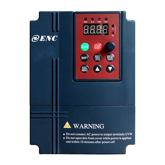
www.enc.net.cn/en Tel/Fax:86-755-26984485/26985120 2 Type and specification of the inverter 2.5 Appearance and parts name explanation LED display digital LED display digital potentiometer Upper cover plate potentiometer keypad keypad connection terminal Control cable nameplate nameplate inlet bottom fitting hole ventilation hole Control cable inlet Power supply input end Power supply input end,…
-
Page 14
www.enc.net.cn/en Tel/Fax:86-755-26984485/26985120 2 Type and specification of the inverter Table 2-2 EDS1000-2S0004~EDS1000-4T0750P mounting size Fixing Inverter type apertu Fig. G.W. (mm) (mm) (mm) (mm) (mm) (mm) (G: general; P: special) (kg) (mm) EDS1000/1300-2S0004 EDS1000/1300-2S0007 EDS1000/1300-2S0015 EDS1000/1300-2S0022 170 123.2 135.5 Fig a EDS1000/EDS1100/1300-4T0007G/0015P EDS1000/EDS1100/1300-4T0015G/0022P EDS1000/1100/1300-4T0022G/0037P… -
Page 15: Product Technic Index And Spec
www.enc.net.cn/en Tel/Fax:86-755-26984485/26985120 2 Type and specification of the inverter 2.7 Outer size of keypad and its fixing box (unit: mm) Fig.2-5 EN-KB5 outer size Fig.2-5 EN-KB5 hole size Fig.2-7 EN-KB6 outer size Fig.2-8 EN-KB6 hole size 2.8 Product technic index and spec Item Item description 3 phase 690V grade, 3 phase 690V ,50Hz/60Hz;…
-
Page 16
www.enc.net.cn/en Tel/Fax:86-755-26984485/26985120 2 Type and specification of the inverter G type: 150% of rating current for1 minute,200% Over loading capacity of rating current for 0.5 second; P type: 120% of rating current for 1 minute; Speed sensorless slip vector control, Control mode open loop V/F control Speed regulation range… -
Page 17
www.enc.net.cn/en Tel/Fax:86-755-26984485/26985120 2 Type and specification of the inverter Impulse square wave signal output of 0~20KHz, pulse output channel can realize output of physical parameter such as setting frequency, output frequency etc. 2 channel of analog signal output,thereinto AO1 channel can be 4~20mA or 0~10V and AO2 Analog output channel channel is 0~10V;… -
Page 18: Installation And Wiring
www.enc.net.cn/en Tel/Fax:86-755-26984485/26985120 3 Installation and wiring 3 Installation and wiring 3.1 Installation ambient 3.1.1 Demand for installation ambient (1) Installed in drafty indoor place, ambient temperature within -10ºC~40ºC, need external compulsory heat sink or reduce the volume if temperature exceeds 40ºC.
-
Page 19: Parts Disassembly And Installation
www.enc.net.cn/en Tel/Fax:86-755-26984485/26985120 3 Installation and wiring Leading divider Fig. 3-2 mounting of multiple inverters 3.2 Parts disassembly and installation 3.2.1 Key board disassembly and installation Mounting claw (1) Disassembly Let the forefinger press finger inlet on the keypad,depress fixing flexible plate on the top lightly, draw it outward, then Hook Mounting claw…
-
Page 20: Wiring Notice Points
www.enc.net.cn/en Tel/Fax:86-755-26984485/26985120 3 Installation and wiring (1) Disassembly First take off 2 screws at sides of the cover and move it a bit outward horizontally, then tilt it at 15 degree and draw it outward at direction shown in right figure, now you can take the cover off. (2) Assembly First put down the cover in parallel with unit body and make it just locked at 2 sides of the inverter, secondly force it ahead and make fixing part on its top…
-
Page 21: Main Loop Terminal Wiring
www.enc.net.cn/en Tel/Fax:86-755-26984485/26985120 3 Installation and wiring (1) Before wiring, assure power supply is cut off completely for 10 minutes and all LED indicator light extinguished. (2) Before internal wiring, confirm that DC volt. Between main loop end P+ and P- fall down to below DC36V.
-
Page 22
www.enc.net.cn/en Tel/Fax:86-755-26984485/26985120 3 Installation and wiring (5) Input side EMI filter Can use EMI filter to inhibit high-frequency conduction disturbance and emission Isolation switch disturbance from inverter power supply wire. Breaker or fuse (6) Output side EMI filter Can use EMI filter to inhibit AC input reactor(in option) emission disturbance noise and wire leakage current from output… -
Page 23: Main Loop Terminal Wiring
www.enc.net.cn/en Tel/Fax:86-755-26984485/26985120 3 Installation and wiring 3.4.2 Main loop terminal wiring For main loop input output terminal, see table 3-1. Table 3-1 main loop input output terminal description Adapted type Main loop terminal End name Function description Zero wire Live wire EDS1000-2S0004 DC volt.
-
Page 24
www.enc.net.cn/en Tel/Fax:86-755-26984485/26985120 3 Installation and wiring R, S, T 3 phase AC 380V input terminal EDS1000-4T0185G~ DC volt. positive end EDS1000-4T0550G Reserved terminal for S T P P+ P- U V W E exterior DC reactor EDS1000-4T0220P~ DC volt. negative end EDS1000-4T0750P U, V, W 3 phase AC output terminal… -
Page 25: Basic Running Wiring Diagram
www.enc.net.cn/en Tel/Fax:86-755-26984485/26985120 3 Installation and wiring Basic running wiring diagram Adapted type: EDS1000-2S0004~2S0037 EDS1000-4T0007~4T0015G EDS1000-4T0022G~EDS1000-4T0750P Braking unit Braking resistance (external,fitting part) (external,fitting part) breaker 3 phase R(L1 220V AC) 380V S(L2 220V AC) 50/60Hz Forward run/stop EDS1000 Reverse run/stop DC amperometer Multi-function 1 4-20mA current signal Multi-function 2…
-
Page 26: Control Loop Collocation And Wiring
www.enc.net.cn/en Tel/Fax:86-755-26984485/26985120 3 installation and wiring 3.6 Control loop collocation and wiring 3.6.1 Location&function of terminal and slide switch: For location of terminal and slide switch on the CPU board, please see Fig.3-10. Function description of terminal provided for the user, please see Table 3-2, function and setup description of slide switch, please see Table 3-3,…
-
Page 27
www.enc.net.cn/en Tel/Fax:86-755-26984485/26985120 3 installation and wiring Table 3-3 function description of slide switch provided for user Factory Symbol Function Setting default : 0~5V voltage signal; YCI: 5V/10V voltage 0~5V input mode selection : 0~10V voltage signal : 0~10V voltage signal; VCI: 5V/10V voltage 0~10V input mode selection… -
Page 28
www.enc.net.cn/en Tel/Fax:86-755-26984485/26985120 3 installation and wiring Input impedance of X7, Multi-function input 4 X7, X8 can be set as X8 input channel: H-speed impulse input port, R=2KΩ for detailed see Chapter 6 Multi-function input 5 Max. output Freq.: Section 6.6 terminal 20KHz Multi-function input 6 function parameter(F5… -
Page 29
www.enc.net.cn/en Tel/Fax:86-755-26984485/26985120 3 installation and wiring optocoupler isolation Open circuit collector output output terminal 1 Used for multi-function Work voltage range: switch output terminal, for Open circuit collector 15~30V detailed see Chapter 6 output terminal 2 Max. output current: Section 6.6 terminal 50mA function parameter (F5 Open circuit collector… -
Page 30: Analog Input Output Terminal Wiring
www.enc.net.cn/en Tel/Fax:86-755-26984485/26985120 3 installation and wiring Table 3-6 CPU board JP1 terminal function Item symbol name Function description Spec TB-TC: always-closed, TA-TC: always-open Relay Inverter Normal: TB-TC closed, TA-TC open Contact capacity: output malfunction Malfunction: TB-TC open, TA-TC AC250V/2A (COSΦ=1) terminal output relay closed…
-
Page 31
www.enc.net.cn/en Tel/Fax:86-755-26984485/26985120 3 installation and wiring (3) YCI terminal accepts analog voltage signal input,wiring mode as follows: YCI current input EDS1000 +10V 0~+10 0~5V Or 0~+5V YCI volt. ― Shielded wire close end grounded 0~10V Fig.3-13 YCI terminal wiring diagram Explanation: relation between YCI input voltage and set frequency is as following figure: 1>… -
Page 32: Communication Terminal Wiring
www.enc.net.cn/en Tel/Fax:86-755-26984485/26985120 3 installation and wiring Analog current output Analog meter 0~10V Analog voltage output 4~20mA Fig.3-14 analog output terminal wiring (1) When inputing anglog signal,can connect filter capacitor or common module inductance between VCI and GND or between CCI and GND or between YCI and GND.
-
Page 33
www.enc.net.cn/en Tel/Fax:86-755-26984485/26985120 3 installation and wiring (3) Connection between inverter RS485 interface and upper machine(with RS232 interface): RS232/RS485 converter Shielded Signal Pin no. cable Terminal explain Name shell 5Vpower positive Sending data line Receivingdata line 5VPower ground Terminal explain Name Name Terminal explain Signal negative end… -
Page 34: Installation Guide For Anti-Jamming
www.enc.net.cn/en Tel/Fax:86-755-26984485/26985120 3 installation and wiring 3.7 Installation guide for anti-jamming Main circuit of the inverter is composed of high-power semiconductor switch gear,so some electromagnetic noise will arise during work,to reduce or stop disturbance to environment,show you assembling method of inverter disturbance suppressing from many aspects such as disturbance suppressing, spot wiring, system grounding, leak current, usage of power supply filter etc.
-
Page 35
www.enc.net.cn/en Tel/Fax:86-755-26984485/26985120 3 installation and wiring (2) Noise spread road ⑧ ② ② ⑥ ⑤ ③ power supply inverter Wireless set meter ④ ⑦ sensor ⑤ motor ① Fig.3-19 noise disturbance spread road sketch (3) basic countermeasure for suppressing disturbance Table 3-7 disturbance suppressing countermeasure table Noise spread… -
Page 36: And The Countermeasure
www.enc.net.cn/en Tel/Fax:86-755-26984485/26985120 3 installation and wiring To prevent parallel or bundled power and weak conducting wire;should keep away from inverter mounted device to the best and its wiring should keep away from power wire of the inverter such as R, S, T, U, V, W etc.. Should pay attention to relative ⑥⑦⑧…
-
Page 37
www.enc.net.cn/en Tel/Fax:86-755-26984485/26985120 3 installation and wiring these electromagnetic on-off electronic device would bring lots of noise during work, so you should pay full attention to when installing them beside the inverter or in the same control chamber with the inverter and must install surge absorbing device as shown in Fig. -
Page 38: Run And Operation Explanation For Inverter
www.enc.net.cn/en Tel/Fax:86-755-26984485/26985120 4 Run and operation explanation for inverter 4 Run and operation explanation for inverter 4.1 Run of inverter 4.1.1 Running order channels There are 3 kinds of order channel for controlling run action of the inverter such as run, stop, jog etc.: 0: keypad Control by key on keypad(factory default).
-
Page 39: Run Mode
www.enc.net.cn/en Tel/Fax:86-755-26984485/26985120 4 Run and operation explanation for inverter 4.1.4 Run mode EDS1000 inverter have 6 kinds of run mode,following is in turn according to their priority: jog run→closed-loop run→PLC run→multisection speed run→ swing frequency run→common run. Shown as Fig.4-1. electrification waiting state…
-
Page 40
www.enc.net.cn/en Tel/Fax:86-755-26984485/26985120 4 Run and operation explanation for inverter The inverter will come into closed-loop run mode when closed –loop run control effective parameter is set(F3.00=1). Namely carry on PID adjustment to specified value and feedback value(proportion integral differential calculation, see F3 group function code) and PID adjustor output is inverter output frequency. -
Page 41: Operation And Use Of Key Board
www.enc.net.cn/en Tel/Fax:86-755-26984485/26985120 4 Run and operation explanation for inverter 4.2 Operation and use of key board 4.2.1 Keypad layout Keypad is main unit for receiving command, displaying parameter. Outer dimension of EN-KB6 is as Fig.4-2: Failure alarm indicator light Forward run indicator light Reverse run indicator light Mode indicator light Current unit(A)
-
Page 42: Led And Indicator Light
www.enc.net.cn/en Tel/Fax:86-755-26984485/26985120 4 Run and operation explanation for inverter Analog Be used to set frequency; when F0.00=0 value set by analog potentiometer potentiometer is frequency provision To increase data or function code (to press it continuously can Increasing button improve increasing speed) To decrease data or function code (to press it continuously can Decreasing button improve decreasing speed)
-
Page 43
www.enc.net.cn/en Tel/Fax:86-755-26984485/26985120 4 Run and operation explanation for inverter supervision parameter in function parameter schedule graph of chapter 5). (2) run parameter display status The inverter enters into run status when receiving effective run command and normally parameter F3.28 decide which status supervision parameter to be displayed on the keypad. -
Page 44: Method For Operating Keypad
www.enc.net.cn/en Tel/Fax:86-755-26984485/26985120 4 Run and operation explanation for inverter (4) function code editing status Under waiting, run or failure alarm status,press key,can enter into MENU editing status(If user password is set,can enter into editing status after inputting the password,see also FF.00 description and Fig.4-10),and editing status is displayed according to three classes menu mode,as shown in Fig.
-
Page 45
www.enc.net.cn/en Tel/Fax:86-755-26984485/26985120 4 Run and operation explanation for inverter LED displayed 50.00 C-01 Para. value C-02 Para. value content Set frequency Output frequency Output current Key-press SHIFT SHIFT operation order parameter C-14 parameter C-03 Output voltage Pulse input SHIFT SHIFT SHIFT ∫…∫… -
Page 46
www.enc.net.cn/en Tel/Fax:86-755-26984485/26985120 4 Run and operation explanation for inverter 3> Parameter protected. All the function code can’t be modified when function code F2.13=1 or 2,in order to avoid wrong operation. Need to set the function code F2.13 to 0 if you want to edit function code parameter. (3) Specified frequency adjustment for common run Take example modifying specified frequency from 50.00Hz to 40.00Hz at F0.00=0 during running for explanation. -
Page 47
www.enc.net.cn/en Tel/Fax:86-755-26984485/26985120 4 Run and operation explanation for inverter (6) See about failure parameter under failure status: LED displayed Fd.06 50:00 Fd.07 45:00 Fd.08 E001 content Failure output freq. Key-press Failure current Failure set freq. SHIFT SHIFT SHIFT operation order 1500 Fd.14 1111… -
Page 48: Inverter Electrification
www.enc.net.cn/en Tel/Fax:86-755-26984485/26985120 4 Run and operation explanation for inverter 4.3 Inverter electrification 4.3.1 Check before electrification Please carry on wiring based on operation requirement provided in “inverter wiring” of this Service manual. start 4.3.2 First electrification Close input side AC power wiring based on 3.5 section supply switch after correct wiring and power supply confirmed,…
-
Page 49: Function Parameter Schedule Graph
www.enc.net.cn/en Tel/Fax:86-755-26984485/26985120 5 Function parameter schedule graph 5 Function parameter schedule graph 5.1 Symbol description × —- parameter can’t be changed in process of running ○ —- parameter can be changed in process of running * —- read-only parameter, unmodifiable 5.2 Function parameter schedule graph F0-Basic run function parameter group Function…
-
Page 50
www.enc.net.cn/en Tel/Fax:86-755-26984485/26985120 5 Function parameter schedule graph × F0.11 Lower limit freq. 0.00-Upper limit freq. 0.01Hz 0.00Hz 0: run at lower limit freq. Lower limit freq. × F0.12 1: stop by slow down run mode 2: free stop Torque boost 0: manual boost ○… -
Page 51
www.enc.net.cn/en Tel/Fax:86-755-26984485/26985120 5 Function parameter schedule graph F2-Auxiliary run function parameter group Function Min. Factory Modifi Name Set range code unit default -cation Analog filter time ○ F2.00 0.00-30.00s 0.01s 0.20s constant Forward reverse ○ F2.01 run dead-section 0.0-3600.0s 0.1s 0.1s time Automatic energy… -
Page 52
www.enc.net.cn/en Tel/Fax:86-755-26984485/26985120 5 Function parameter schedule graph 0000-1111 first bit: running time 0: not display 1: display second bit: accumulative time 0: not display LED display 1: display ○ F2.11 0000 control 1 third bit: input terminal status 0: not display 1: display kilobit(fourth bit): output terminal status… -
Page 53
www.enc.net.cn/en Tel/Fax:86-755-26984485/26985120 5 Function parameter schedule graph LED second bit: data format 0: 1-8-1format, no checkout 1: 1-8-1 format, even checkout 2: 1-8-1 format, odd checkout 0-127,127 is broadcast address. The inverter only × F2.15 Local address receive but not send when it is set to be 127, 0 is address for main device. -
Page 54
www.enc.net.cn/en Tel/Fax:86-755-26984485/26985120 5 Function parameter schedule graph Jumping freq. 3 × F2.50 0.00-30.00Hz 0.01Hz 0.00Hz range ○ F2.51 Sett run time 0-65535 hours Run time F2.52 0-65535 hours accumulation 0: a ASCII frame of 14 byte or 18 byte 1: a hex frame of 8 byte or 10 byte, original response not changed RS485/232 2: a hex frame of 8 byte or 10 byte, 12 command has… -
Page 55
www.enc.net.cn/en Tel/Fax:86-755-26984485/26985120 5 Function parameter schedule graph ○ F3.11 Sampling cycle T 0.01-1.00s 0.01s 0.10s ○ F3.12 Deviation limit 0.0-20.0(%)percentage relative to 10.00V 0.1(%) 2.0(%) Integral separation ○ F3.13 PID adjusting 0.0-100.0% 0.1% 100.0% threshold Closed-lop preset ○ F3.14 0-upper limit frequency 0.01Hz 00.00 frequency… -
Page 56
www.enc.net.cn/en Tel/Fax:86-755-26984485/26985120 5 Function parameter schedule graph 13: analog input YCI 14: exterior pulse inputs YCI run-in delay ○ F3.29 0.0-999.9s 10.0 time 0: inverter running(RUN) 1: frequency arriving signal(FAR) 2: frequency level detect signal (FDT1) 3: reserved 4: overload warning alarm signal (OL) 5: output frequency reach high limit(FHL) 6: output frequency reach low limit(FLL) 7: inverter under voltage blockage stop (LU) -
Page 57
www.enc.net.cn/en Tel/Fax:86-755-26984485/26985120 5 Function parameter schedule graph 0: Acce/Dece time 1 1: Acce/Dece time 2 2: Acce/Dece time 3 3: Acce/Dece time 4 4: Acce/Dece time 5 5: Acce/Dece time 6 6: Acce/Dece time 7 ○ F4.02 Section 1 run time 0-6000.0 10.0 ○… -
Page 58
www.enc.net.cn/en Tel/Fax:86-755-26984485/26985120 5 Function parameter schedule graph 32: swing frequency jump-in 33: external interruption input 34: interior counter clearing end 35: interior counter triggering end 36: interior timer clearing end 37: interior timer triggering end 38: pulse frequency input(only effective forX7,X8) 39: reserved 40: reserved 41: reserved… -
Page 59
www.enc.net.cn/en Tel/Fax:86-755-26984485/26985120 5 Function parameter schedule graph 24: reserved Open circuit collector output × F5.11 Same as above terminal OC2 output setting Open circuit collector output × F5.12 Same as above terminal OC3 output setting Open circuit collector output × F5.13 Same as above terminal OC4… -
Page 60
www.enc.net.cn/en Tel/Fax:86-755-26984485/26985120 5 Function parameter schedule graph F6-Traverse special function parameter group Function Min. Factory Modifi Name Set range code unit default -cation Traverse function 0: traverse function not used × F6.00 selection 1: traverse function used LED first bit: jump-in mode 0: automatic jump-in mode 1: terminal manual jump-in mode LED second bit:… -
Page 61
www.enc.net.cn/en Tel/Fax:86-755-26984485/26985120 5 Function parameter schedule graph PULSE max. provision corresponding ○ F7.17 0.00-high limit frequency 0.01 Hz 50.00 Hz freq. F8-Motor and vector control parameter group Function Min. Factory Modifi Name Set range code unit default -cation 0: V/F control ×… -
Page 62
www.enc.net.cn/en Tel/Fax:86-755-26984485/26985120 5 Function parameter schedule graph Overload warning ○ F9.05 20-200(%) 1(%) 130(%) alarm checkout level Overload warning ○ F9.06 0.0-20.0s 0.1s 5.0s alarmDelay time Overvoltage stall 0: ban × F9.07 selection 1: allow Overvoltage stall ○ F9.08 120-150(%) 1(%) 130(%) point… -
Page 63
www.enc.net.cn/en Tel/Fax:86-755-26984485/26985120 5 Function parameter schedule graph C-Supervision function parameter group Function Min. Factory Modifi Name Description code unit default -cation C-00 Set frequency Current set frequency 0.01HZ C-01 Output freq. Current output freq. 0.01HZ C-02 Output current Virtual value of current output current 0.1A C-03 Output voltage… -
Page 64: Detailed Function Description
www.enc.net.cn/en Tel/Fax:86-755-26984485/26985120 Detailed function description Detailed function description Listed column content for parameter function code description in this chapter is as follows: Code Name Set range or description Factory default 6.1 Basic run function parameter group: F0 F0.00 Frequency input channel selection range: 0~11 0: keypad analog potentiometer setting.
-
Page 65
www.enc.net.cn/en Tel/Fax:86-755-26984485/26985120 Detailed function description 11: terminal PWM pulse width set frequency. Relation between frequency and input information is determined by function code F7.00~F7.17 when frequency input channel is 4, 5, 6, 7,please see Section 6.8. note F0.01 Freq. digit setting range: low limit~high limit 50.00Hz F0.01 parameter is original set frequency of the inverter when frequency setting… -
Page 66
www.enc.net.cn/en Tel/Fax:86-755-26984485/26985120 Detailed function description F0.04 Acce/Dece mode selection range: 0, 1 0: linear Acce/Dece mode. Output frequency increases or decreases according to constant slope, just as shown in Fig.6-1. 1: S curve Acce/Dece mode. Output frequency increases or decreases according to S curve, just as shown in Fig.6-2. -
Page 67
Fig.6-3 Acce/Dece time definition (1) In EDS1000 series inverter 7 kinds of Acce/Dece time are defined in total, here we only define Acce/Dece time 1,Acc/Dec time 2~7 are defined in F2.18~F2.29, please refer to Section 6.3. -
Page 68
www.enc.net.cn/en Tel/Fax:86-755-26984485/26985120 Detailed function description saturation when lightly loaded. 1: automatic torque boost. Torque boost voltage varies as stator current of the motor changes,bigger stator current corresponds to bigger boost voltage. inverter output current F0.14 ×motor rated volt.× Boost volt.= 2×inverter rated current F0.14 Torque boost… -
Page 69: Start, Stop, Braking Function Parameter Group:f1
www.enc.net.cn/en Tel/Fax:86-755-26984485/26985120 Detailed function description characteristic to reach better energy save result while the inverter is driving degressive torque load such as blower and water pump etc.. If F0.15=4, you can set V/F curve yourself by setting F2.37-F2.44 parameters. As shown in Fig.6-5b, by setting three inflexion point (V1,F1), (V2,F2), (V3,F3), you can define V/F curve arbitrarily to apply to special load.
-
Page 70
www.enc.net.cn/en Tel/Fax:86-755-26984485/26985120 Detailed function description F1.01 Starting frequency range: 0.0-10.00Hz 0.00Hz F1.02 Starting freq. duration time range: 0.0-20.0S 0.0S Starting frequency means initial frequency at which the inverter start up,as fs shown in Fig.6-6;Starting freq. holding time means consecutive run time during which the inverter run at starting frequency,as t shown in Fig.6-6. -
Page 71: Auxiliary Run Function Parameter Group: F2
www.enc.net.cn/en Tel/Fax:86-755-26984485/26985120 Detailed function description F1.05 Stop mode Range: 0, 1, 2 0: Dece stop. The inverter reduces output frequency gradually according to set Dece time upon receival of stop command and stops running after frequency is reduced to 0. 1: free stop.
-
Page 72
www.enc.net.cn/en Tel/Fax:86-755-26984485/26985120 Detailed function description To reach better energy save result, the inverter would detect load current to get the purpose of automatic energy save. 0: no action 1: action Empty or lightly loaded motor can get the purpose of energy save by detecting load current to adjust output voltage properly. -
Page 73
www.enc.net.cn/en Tel/Fax:86-755-26984485/26985120 Detailed function description Carrier frequency mainly affects motor noise and heat consumption during running. Relation between carrier frequency and motor noise, current leakage, disturbance is as follows: Carrier frequency increase(↑),motor noise decrease(↓),motor current leakage increase(↑),disturbance to environment increase(↑); Carrier frequency decrease (↓),motor noise increase (↑),motor current leakage decrease (↓),disturbance to environment decrease (↓)。… -
Page 74
www.enc.net.cn/en Tel/Fax:86-755-26984485/26985120 Detailed function description Jog accelerating time means time during which the inverter accelerate from 0Hz to high limit frequency,Jog Dec time means time during which the inverter decelerate from high limit frequency to 0Hz. Jog decelerating time freq. freq. -
Page 75
www.enc.net.cn/en Tel/Fax:86-755-26984485/26985120 Detailed function description 13: VCI,CCI any nonzero value effective,VCI preferred 14: reserved 15: RS485+CCI 16: RS485-CCI 17: RS485+VCI 18: RS485-VCI 19: RS485+keypad analog potentiometer 20: RS485- keypad analog potentiometer 21: VCI+ keypad analog potentiometer 22: VCI- keypad analog potentiometer 23: CCI+ keypad analog potentiometer 24: CCI- keypad analog potentiometer 25: reserved… -
Page 76
www.enc.net.cn/en Tel/Fax:86-755-26984485/26985120 Detailed function description F2.12 make use of 4 bit of the parameter to set if C-11—C-14 is displayed in parameter, thereinto 0 indicates not displayed, 1 indicates displayed. Set parameter of 4 bit is as following figure: C-11: analog input VCI C-12: analog input YCI C-13: analog input CCI C-14: outer pulse input… -
Page 77
www.enc.net.cn/en Tel/Fax:86-755-26984485/26985120 Detailed function description range: LED 1 bit: 0~5 F2.14 communication configuration LED 2 bit: 0, 1, 2 F2.14 make use of 1 bit, 2 bit to set baud rate and data format of serial communication,thereinto LED 1 bit represents communication baud rate, set value as follows: 0: 1200BPS 1: 2400BPS… -
Page 78
www.enc.net.cn/en Tel/Fax:86-755-26984485/26985120 Detailed function description F2.18 Acce time 2 range: 0.1-6000.0 20.0 F2.19 Dece time 2 range: 0.1-6000.0 20.0 F2.20 Acce time 3 range: 0.1-6000.0 20.0 F2.21 Dece time 3 range: 0.1-6000.0 20.0 F2.22 Acce time 4 range: 0.1-6000.0 20.0 F2.23 Dece time 4 range: 0.1-6000.0… -
Page 79
www.enc.net.cn/en Tel/Fax:86-755-26984485/26985120 Detailed function description 0.00-F2.39 F2.37 VF frequency value 0 10.00Hz 0.00-F2.40 F2.38 VF voltage value 0 20.00% F2.37-F2.41 F2.39 VF frequency value 1 20.00Hz F2.38-F2.42 F2.40 VF voltage value 1 40.00% F2.39-F2.43 F2.41 VF frequency value 2 25.00Hz F2.40-F2.44 F2.42 VF voltage value 2… -
Page 80: Closed-Loop Run Function Parameter Group: F3
www.enc.net.cn/en Tel/Fax:86-755-26984485/26985120 Detailed function description F2.51 Set run time range: 0-65535h F2.52 Run time accumulation range: 0-65535h After run accumulative time reach set run time (F2.51),the inverter will output indicator signal,please refer to F5.10~F5.13 function introduction. F2.52 denotes accumulative run time of the inverter from leaving factory tonow. RS485/232 communication F2.53 range: 0-4…
-
Page 81
www.enc.net.cn/en Tel/Fax:86-755-26984485/26985120 Detailed function description EDS1000 built-in PID adjustor make up of control system and its work principle chart is as follows: proportion gain (F3.08) specified value error limit adjusting integral Closed-loop closed-loop (F3.12) gain (F3.04,F3.06) output specified value (F3.09) differenti- al gain (F3.10) -
Page 82
www.enc.net.cn/en Tel/Fax:86-755-26984485/26985120 Detailed function description cycle, error limit (F3.08~F3.12) F3.00 Closed-loop run control selection range: 0, 1, 2 0: closed-loop run control ineffective 1: PID closed-loop run control effective 2: constant pressure water supply PID control effective This parameter is mainly used for implementing one-driving-two water supply function. -
Page 83
www.enc.net.cn/en Tel/Fax:86-755-26984485/26985120 Detailed function description range: 0.0-max. F3.04 min. specified value 0.0(%) specified value corresponding feedback F3.05 range: 0.0-100.0(%) 0.0(%) value of min. specified value range: min. specified F3.06 max. specified value value 100.0(%) value -100.0(%) corresponding feedback F3.07 range: 0.0%-100.0(%) 100.0(%) value of max. -
Page 84
www.enc.net.cn/en Tel/Fax:86-755-26984485/26985120 Detailed function description F3.12 Deviation limit range: 0.0-20.0(%) 2.0(%) For Max. offset of closed-loop specified value,as shown in Fig.6-17,PID adjustor stops adjusting when feedback value is within this range. To utilize this function reasonably redound to harmonizing the conflict between system output precision and stabilization. -
Page 85
www.enc.net.cn/en Tel/Fax:86-755-26984485/26985120 Detailed function description the scope of F3.12 (deviation limit), and the inverter operating frequency is under the F3.16 (sleep frequency), after the F3.18 (sleep delay time), the inverter will enter a sleep state, operating frequency will drop to 0.00HZ in order to save energy conservation and protect motor. -
Page 86
www.enc.net.cn/en Tel/Fax:86-755-26984485/26985120 Detailed function description This parameter defines the action delay time of magnetic control conductor when it’s from power source to variable frequency or from variable frequency to power source. range: 0000-9999 F3.25 Automatic switchover interval 0000 By setting this parameter, can achieve the function of rust-proof die of the motor, the inverter can delay time by it and then automatically smart switch run pumps and static pump. -
Page 87: Simple Plc Function Parameter Group:f4
PLC circle finishing indication Fig.6-19 simple PLC run EDS1000 series inverter simple PLC run function can provide 7 kinds of multi-speed operation mode, take the fowling 7speed for example Figure 6 -20 , a1~ a5, d1~d5Is the speed up time and the deceleration time of the stage, they are…
-
Page 88
www.enc.net.cn/en Tel/Fax:86-755-26984485/26985120 Detailed function description setted by the acceleration time parameters F 0.08,F0.09and F2.18~F2.29, a total of seven kinds of parameters, the run frequency and run time of f1~ f7, T1~ T7 are setted by function code F4.01~f4.14. Simple PLC run RUN command Fig.6-20 stop after PLC single circle PLC step finishing and circle finishing indication can be realized by outputting… -
Page 89
www.enc.net.cn/en Tel/Fax:86-755-26984485/26985120 Detailed function description RUN command STOP command Fig.6-21 holding mode after PLC single circle PLC run T1 T2 T3 T4 T5 T6 T7 T1 T2 T3 T4 T5 T6 T7 T1 Second circle First circle RUN command STOP Fig.6-22 PLC consecutive circle mode 3: consecutive circulation. -
Page 90
www.enc.net.cn/en Tel/Fax:86-755-26984485/26985120 Detailed function description Interruption signal output freq.Hz Time t Step 1 Step 2 Step 2 residual time Used time : step 1 accelerating time : step 2 accelerating time : step 3 accelerating time : step 2 decelerating time : step 1 frequency : step 2 frequency : step 3 frequency… -
Page 91: Terminal Correlative Function Parameter Group: F5
www.enc.net.cn/en Tel/Fax:86-755-26984485/26985120 Detailed function description F4.01~F4.14 utilize LED 1st bit, 2nd bit, 3rd bit to separately define frequency setting,direction and accelerating decelerating time of PLC Run, see following for detail: LED1 bit: frequency setting 0: multi-step frequency i i=1~7 is defined by F2.30~F2.44. 1: frequency is determined by function code F0.00 LED 2 bit: run direction selection…
-
Page 92
www.enc.net.cn/en Tel/Fax:86-755-26984485/26985120 Detailed function description Table 6-2 multifunction input function selection table item corresponding function item corresponding function Leave control terminal unused Multi-step speed control terminal 1 Multi-step speed control terminal 2 Multi-step speed control terminal 3 Multi-step speed control terminal 4 External forward run jog control External reverse run jog control Acce/Dece time selecting terminal 1… -
Page 93
www.enc.net.cn/en Tel/Fax:86-755-26984485/26985120 Detailed function description Table 6-3 multi-step speed run selection table Frequency setting Common run frequency Multi-step frequency 1 Multi-step frequency 2 Multi-step frequency 3 Multi-step frequency 4 Multi-step frequency 5 Multi-step frequency 6 Multi-step frequency 7 Above multi-step frequency can be used in multi-step speed run and simple PLC run, please see below an example of multi-step speed run: We now define control terminal X1, X2, X3, separately as follows: After set F5.00=1, F5.01=2, F5.03=3, X1, X2, X3, are used for realizing… -
Page 94
www.enc.net.cn/en Tel/Fax:86-755-26984485/26985120 Detailed function description 3 phase breaker 3 phase AC power supply Fig.6-25 Fig.6-26 multi-step speed run exterior device failure always-open input 5~6: external jog run control input JOGF/JOGR. When run command channel is set to terminal run command channel F0.02=1,JOGF is jog forward run ,… -
Page 95
www.enc.net.cn/en Tel/Fax:86-755-26984485/26985120 Detailed function description RESET function of key on the operation panel. 12: free stop input. This function is same as free stop during running defined in F1.05,but it’s realized by control terminal to be convenient for long-distance control. 13: exterior stop command. -
Page 96
www.enc.net.cn/en Tel/Fax:86-755-26984485/26985120 Detailed function description 22: simple PLC pause command. Implement pause control to PLC process during running,run at zero frequency when this terminal is effective,not time for PLC run;after ineffective implement automatic speed tracking start and continue PLC run. For application method please refer to function description of F4.00~F4.14. -
Page 97
www.enc.net.cn/en Tel/Fax:86-755-26984485/26985120 Detailed function description Table 6-6 Run command channel logic mode Run command Run command Run command channel selection channel selection channel selection Run command channel terminal 3 terminal 2 terminal 1 hold run command channel keypad run command channel end run command channel (keypad STOP command… -
Page 98
www.enc.net.cn/en Tel/Fax:86-755-26984485/26985120 Detailed function description 39: reserved 40: reserved 41: reserved 42: reserved F5.08 FWD/REV run mode selection range: 0-3 This parameter defines 4 kinds of exterior terminal control mode for inverter running. 0: 2-wire control mode 1 run command EDS1000 stop reverse run… -
Page 99
www.enc.net.cn/en Tel/Fax:86-755-26984485/26985120 Detailed function description Xi is multifunction input terminal of X1~X8, here should define its corresponding terminal function as No. 19 “3-wire run control” function. 3: 3-wire control mode 2 SB1: stop button SB2: run button EDS1000 run direction selection Forward run Reverse run… -
Page 100
www.enc.net.cn/en Tel/Fax:86-755-26984485/26985120 Detailed function description Overload warning signal(OL) Output Freq. reach high limit(FHL) Inverter stop for under voltage Output Freq. reach low limit(FLL) blockage (LU) Stop for exterior failure(EXT) Inverter zero rotate speed running PLC running Simple PLC segment run finished PLC finish one cycle run Reserved Inverter ready to run(RDY) -
Page 101
www.enc.net.cn/en Tel/Fax:86-755-26984485/26985120 Detailed function description frequency but in run status, output indicator signal. 10: PLC running 11: Simple PLC segment running finished. After simple PLC current segmentrun is finished, output indicator signal(single pulse signal, width 500ms). 12: PLC finish one cycle run 13: reserved 14: Inverter ready to run(RDY). -
Page 102
www.enc.net.cn/en Tel/Fax:86-755-26984485/26985120 Detailed function description 24: Reserved F5.14 Freq. arriving(FAR)detect range range: 0.00-50.00Hz 5.00Hz This parameter is supplementary definition to No. 1 function in Table 6-7.As shown in Fig.6-32,when output frequency of the inverter is within high&low detect range of set frequency,output pulse signal. FDT1(freq. -
Page 103
www.enc.net.cn/en Tel/Fax:86-755-26984485/26985120 Detailed function description F5.21 Analog output(AO2)gain range: 0.10-2.00 1.00 F5.22 Analog output(AO2) offset range: 0.00-10.00V 0.00 Same as F5.18 and F5.19 function parameter description. This function makes real-time effect to analog output when it’s being modified. note F5.23 DO terminal output function selection range: 0~9 Same as F5.17 function parameter description. -
Page 104: Traverse Special Function Parameter Group: F6
www.enc.net.cn/en Tel/Fax:86-755-26984485/26985120 Detailed function description F5.27 Interior timing setting range: 0.1-6000.0s 60.0 This parameter is used to set timing time of interior timer of the inverter. The timer is activated by exterior triggering end(triggering end selected by F5.00~F5.07), the timer begins timing upon receiving exterior triggering signal, after it’s up to timing time one effective pulse signal of 0.5s will be outputted from relative OC end.
-
Page 105
www.enc.net.cn/en Tel/Fax:86-755-26984485/26985120 Detailed function description F6.04 Traverse cycle range: 0.1-999.9S 10.0S Whole time for a cycle including traverse rising, descending process. Triangle wave range: 0.0-98.0(%)(traverse F6.05 50.0(%) rising time cycle) Define runtime of traverse rising segment=F6.04×F6.05 (s),runtime of descending segment = F6.04 × (1-F6.05) (s). Please refer to description in Fig.6-35. -
Page 106: Frequency Provision Function Parameter Group: F7
www.enc.net.cn/en Tel/Fax:86-755-26984485/26985120 Detailed function description 6.8 Frequency provision function parameter group: F7 F7.00 VCI min. provision range: 0.00-F7.02 0.0V VCI min. provision range: 0.00-high limit F7.01 0.00Hz corresponding freq. frequency F7.02 VCI max. provision range: 0.00-10.00V 9.9V VCI max. provision range: 0.00-high limit F7.03 50.00Hz…
-
Page 107
www.enc.net.cn/en Tel/Fax:86-755-26984485/26985120 Detailed function description range: F7.14(PULSE min. F7.16 PULSE max. provision provision)-F7.13(max. 10.0K input pulse) PULSE max. provision range: 0.00-high limit F7.17 50.00Hz corresponding freq. frequency F2.00 sets the analog channel filtering time constant, to filter input signal, the more long filtering time is, the more great anti-jamming ability is, but response speed descend;… -
Page 108: Motor And Vector Control Parameter Group: F8
www.enc.net.cn/en Tel/Fax:86-755-26984485/26985120 Detailed function description See below relation curve of YCI and set frequency: fmax Amax Amin dead band fmin A:YCI provision Amin: min. provision fmin: corresponding freq. to min. provision Amax: max. provision fmax: corresponding freq. to max. provision See below relation curve of PULSE and set frequency: Set freq.
-
Page 109
www.enc.net.cn/en Tel/Fax:86-755-26984485/26985120 Detailed function description Depend on F8.01 Motor rated voltage range: 1-480V device type Depend on F8.02 Motor rated current range: 0.1-999.9A device type Depend on F8.03 Motor rated frequency range: 1.00-400.0Hz device type Depend on F8.04 Motor rated speed range: 1-9999r/min device type Depend on… -
Page 110: Protection Function Parameter Group:f9
www.enc.net.cn/en Tel/Fax:86-755-26984485/26985120 Detailed function description Motor stability coefficient range: 0—4 F8.15 Filter time displayed instead freq. range: 0~999 F8.16 If surge happens or the motor run unstably, you can eliminate surge by increasing F8.15. F8.17 Motor speed correction factor Range :0-9999% 100% This parameter check display error, have no effect on the actual value.
-
Page 111
www.enc.net.cn/en Tel/Fax:86-755-26984485/26985120 Detailed function description 0: no action. No motor overload protection characteristic(apply with caution),here the inverter have no overload protection for load motor; 1: inverter cut off output at once. The inverter cut off output and motor stop freely when overload, overheat take place. Motor overload protection F9.04 range: 20.0-120.0(%) -
Page 112
www.enc.net.cn/en Tel/Fax:86-755-26984485/26985120 Detailed function description 0: banned 1: allowed Actual descending rate of motor speed may be lower than that of output frequency due to effect from load inertia when the inverter is in decelerating run process, here the motor will feed electric energy back to inverter which will make DC bus-bar voltage of the inverter increase, overvoltage protection will takes place if not take steps. -
Page 113: Failure Record Function Parameter Group: Fd
www.enc.net.cn/en Tel/Fax:86-755-26984485/26985120 Detailed function description By automatic current limiting function the inverter can limit load current not to exceed automatic current limiting level set by F9.09 to avoid tripping out for failure caused by rushing current. This function is especially suitable for some biggish inertia or acutely changing load occasion.
-
Page 114: Password And Manufacturer Function Parameter Group: Ff
www.enc.net.cn/en Tel/Fax:86-755-26984485/26985120 Detailed function description Fd.06 Set freq. at previous failure range: 0-high limit Fd.07 Output freq. at previous failure range: 0-high limit Fd.08 Output current at previous failure range: 0-999.9A Fd.09 Output volt. at previous failure range: 0-999V Fd.10 DC bus-bar volt.
-
Page 115: Stop Assistant Function Parameter Group: Fa
www.enc.net.cn/en Tel/Fax:86-755-26984485/26985120 Detailed function description 6.13 Stop assistant function parameter group: FA FA.00 Auxiliary DC brake time Range:0.0-20.0s 0.0s FA.01 Auxiliary DC brake voltage Range:0-15(%) Auxiliary DC brake means when the inverter stop DC brake is finished give the second stage DC braking. Role in some special circumstances require rapid braking, and stop long time in the state of DC braking, but to prevent motor heat circumstances.
-
Page 116: Troubleshooting
www.enc.net.cn/en Tel/Fax:86-755-26984485/26985120 7 Troubleshooting 7 Troubleshooting 7.1 Failure and countermeasure Possible failure types in EDS1000 are shown in Table 7-1 and failure code is from E001 to E023. Some failure code is reserved for intelligent automatic diagnosis function which will be executed continuously in future. When failure takes place in the inverter, the user should check according to note of this table first and record failure phenomena detailedly.
-
Page 117
www.enc.net.cn/en Tel/Fax:86-755-26984485/26985120 7 Troubleshooting E008 Inverter Accel time is set to too short Prolong accelerating time overload Reduce DC injection braking DC injection braking is too big current,prolong braking time improper V/F curve Adjust V/F curve and torque boost Restart rotating motor Set speed checking restart function power source voltage is too low check power source voltage Load is too big… -
Page 118: Failure Record Lookup
www.enc.net.cn/en Tel/Fax:86-755-26984485/26985120 7 Troubleshooting Baud rate set improperly set Baud rate properly STOP press key to reset, RESET Serial port communication error E016 RS485 look for service communication Failure warning parameter set failure Modify F2.16, F2.17 improperly Check if upper device work and wiring Upper device doesn’t work is correct E017 reserved…
-
Page 119: Failure Reset
www.enc.net.cn/en Tel/Fax:86-755-26984485/26985120 7 Troubleshooting 7.3 Failure reset (1) Before reset you must find out reason of failure downright and eliminate it, otherwise may cause permanent damage to the inverter. (2) If can’t reset or failure takes place again after resetting, should look for reason and continuous resetting will damage the inverter.
-
Page 120: Maintenance
www.enc.net.cn/en Tel/Fax:86-755-26984485/26985120 8 Maintenance 8 Maintenance 8.1 Routine maintenance When you use ESD1000 series you must assemble and operate it according to demand listed in this《service manual》strictly. During run state, temperature, humidity, vibration and aging parts may affect it. To avoid this, it is recommended to perform routine inspections.
-
Page 121: Repair Guarantee
www.enc.net.cn/en Tel/Fax:86-755-26984485/26985120 8 Maintenance (2) filter electrolyte capacitance When frequent-changing load causes increasing pulsant current and aging electrolyte under high ambient temperature, the electrolyte capacitance may be damaged and here should replace it. 8.3 Repair guarantee (1) Within 18 months from purchasing date, if failure caused by inverter itself takes place under normal conservation and usage, we will provide free repair service.
-
Page 122: Fitting Parts
www.enc.net.cn/en Tel/Fax:86-755-26984485/26985120 9 Fitting parts 9 Fitting parts 9.1 Communication subassembly 9.1.1 Long-distance operation key board Maximum electric distance from local keypad to inverter is 2m. RS485 communication mode is adopted between inverter and long-distance keypad,only a four-core cable is needed between them and maximum electric distance can reach 1000m.They communicate with each other in main-auxiliary mode, namely take long-distance keypad as main device and inverter as auxiliary one.
-
Page 123: Examples
www.enc.net.cn/en Tel/Fax:86-755-26984485/26985120 10 Examples 10 Examples 10.1 Common speed regulation running 10.1.1 Basic wiring diagram 3 phase breaker motor EDS1000 failure waring light ENTER DATA cymometer Fig.10-1 10.1.2 Set following basic parameter: (1) set parameter F8.01-F8.06 according to rated value of the motor. (2) set F0.00 parameter to 0,…
-
Page 124: Terminal Control Running
www.enc.net.cn/en Tel/Fax:86-755-26984485/26985120 10 Examples 10.2 Terminal control running 10.2.1 Basic wiring diagram 3 phase breaker motor EDS1000 3 phase 380V 50/60Hz failure warning light forward run reverse run 10V/5V specified signal 10K ammeter Fig.10-2 10.2.2 Parameter setting (1) Set parameter F8.01-F8.06 according to rated value of the motor. (2) Set F0.00 parameter to 4~6 to choose VCI, CCI, YCI accordingly, can accept frequency set signal within 0~10V.
-
Page 125: Multi-Step Speed Control Running
www.enc.net.cn/en Tel/Fax:86-755-26984485/26985120 10 Examples 10.3 Multi-step speed control running 10.3.1 Parameter setting (1) Set parameter F8.01-F8.06 according to rated value of the motor. (2) Set F0.02 parameter to 1,to choose terminal run command channel. (3) F2.30-F2.44: multi-step speed frequency setting. (4) F5.00-F5.07 set multi-step speed terminal control function.
-
Page 126: Closed-Loop Control System
www.enc.net.cn/en Tel/Fax:86-755-26984485/26985120 10 Examples 10.3.3 Realized function (1) make use of external on-off quantum signal to control start/stop of the motor. (2) make use of external on-off quantum signal to make the motor run at set frequency. (3) bear free stop and reset function by utilizing external on-off quantum signal. (4) bear warning alarm and PLC run indication function.
-
Page 127: Consecutive Action Running
www.enc.net.cn/en Tel/Fax:86-755-26984485/26985120 10 Examples tomake constant voltage, constant temperature, constant current etc. available. (2) can control start/stop of the motor from long distance. (3) bear failure alarm and current indicator function. 10.4.4 Application field Applied in field where need stable system, pressure, flux such as blower pump, constant pressure water supply, air compressor, air conditioner, freezer cooling tower, music fountain, heat supply etc..
-
Page 128: Application To Constant Pressure Water Supply
www.enc.net.cn/en Tel/Fax:86-755-26984485/26985120 10 Examples passed to 2# inverter through serial communication. 10.5.4 Application field Applied in field such as conveyer belt, coiler, factory production line, food chemistry etc. 10.6 Application to constant pressure water supply 10.6.1 Summary for constant pressure water supply board This constant pressure water supply board (hearafter in 10.6 referenced as “the board”) is constant pressure water supply controller for multiple pumps, and it has to work with EDS1000 to control constant pressure water supply system for…
-
Page 129
www.enc.net.cn/en Tel/Fax:86-755-26984485/26985120 10 Examples ENC constant pressure water supply board COM Y Z1 Z2 A B +24V X1 X2 +24V Fig.10-7 connection between water supply controller and inverter Explanation for terminals: A, B terminals of constant pressure water supply board are for RS485 receving and sending, Z1 is over pressure signal output terminal when pump increased, Z2 is pressure falling signal output terminal when pump reduced, Y is fire fighting pump control signal input terminal, +24V, COM are respectively power supply input terminal and grounding terminal of the board. -
Page 130
www.enc.net.cn/en Tel/Fax:86-755-26984485/26985120 10 Examples frequency. Bypass run means that the motor is connected to power source directly. Variable frequency/ bypass switch means process from inverter drive to power source drive or from power source drive to inverter drive. (2) Operation mode a. -
Page 131
www.enc.net.cn/en Tel/Fax:86-755-26984485/26985120 10 Examples order to avoid water pressure fluctuation when pump adding or reducing. For detailed parameter setting information, please see below table. function name set range explanation code Set according to actual F0.08 Acce time 1 situation F0.09 Dece time 1 Same as above F0.10… -
Page 132
www.enc.net.cn/en Tel/Fax:86-755-26984485/26985120 10 Examples Input terminal X1 This parameter must be set to 33: F5.00 function selection external interruption input The output setting of output terminal This parameter is used when choose F5.10 of open collector OC1 inverter to supply water The output setting of output terminal F5.11 Same as above… -
Page 133
www.enc.net.cn/en Tel/Fax:86-755-26984485/26985120 10 Examples (2) Basic wiring diagram 3 phase breaker inverter M1-3 3 phase breaker 2 phase breaker Constant pressure M2-3 Water supply controller M3-3 M4-3 Fig.10-10 basic wiring diagram for constant pressure water supply controller Description: (1B,C1B), (1G,C1G), (2B,C2B), (2G,C2G), (3B,C3B), (3G,C3G), (4B,C4B), (4G,C4G) denote respectively 2 terminals corresponding to control terminal“No.1 variable frequency”, “No.1 bypass”, “… -
Page 134: Serial Port Rs485 Communication Protocol
11.1 Summarization We provide general RS485/RS232 communication interface in our Inverters (such as EDS1000 series, EDS2000 series, EDS2800 series, etc.) for the user. Through this communication interface upper device (such as PC, PLC controller etc.) can perform centralized monitor to the inverter (such as to set inverter…
-
Page 135
www.enc.net.cn/en Tel/Fax:86-755-26984485/26985120 11 Serial port RS485 communication protocol (4) Auxiliary device report current failure information to mainframe in the last response frame. (5) EDS1000 provides RS485 interface. 11.2.3 Transport mode Asynchronous serial,semiduplex transport mode. Default format and transport rate: 8-N-1,9600bps.For specific parameter setting please see description for F2.14~F2.17 group function code. -
Page 136
www.enc.net.cn/en Tel/Fax:86-755-26984485/26985120 11 Serial port RS485 communication protocol Remark: (1) “Setting data area” and “run data area” may not be existent in some command/data frame format, so in protocol command list it’s marked with “nothing”. (2) In protocol effective character set is: ~, 1, 2, 3, 4, 5, 6, 7, 8, 9, A, B, C, D, E, F and hex data 0DH,ASCII lowercase a, b, c, d, e, f are invalid. -
Page 137
www.enc.net.cn/en Tel/Fax:86-755-26984485/26985120 11 Serial port RS485 communication protocol data of “command area”, “index (2)“command area”data overrun; area” and “running data area” are (3)“index area”data overrun; (4) frame length error/non ASCII byte not reported. exist in area except frame head, frame end. -
Page 138
www.enc.net.cn/en Tel/Fax:86-755-26984485/26985120 11 Serial port RS485 communication protocol (5) checkout sum Data meanings: frame checkout,4 byte, ASCII. Calculation method: accumulative sum of ASCII code value of all byte from “auxiliary device address”to“run data”. (6) frame end Hex 0D,single byte. 11.2.6 Protocol command list Frame 7E and frame end 0D, address, checkout sum,ASCII character format are omitted in following description. -
Page 139
www.enc.net.cn/en Tel/Fax:86-755-26984485/26985120 11 Serial port RS485 communication protocol auxiliary device ~010C00040198r reverse run forward auxiliary device 0Hz~ high forward run with ~010C00050FA00280r 0.01Hz boot-strap limit freq. run freq. provision set freq. =40.00Hz reverse auxiliary device 0Hz~ high reverse run with ~010C00060FA00281r 0.01Hz boot-strap limit freq. -
Page 140
www.enc.net.cn/en Tel/Fax:86-755-26984485/26985120 11 Serial port RS485 communication protocol Query auxiliary device software ~010F00000197r version Table 11-5 response state word meanings of reading inverter state command Signification description Bit0 Stop/run state Stop Bit1 Logo for under voltage Normal Under voltage Bit2 FWD/REV run logo Forward run Reverse run… -
Page 141
www.enc.net.cn/en Tel/Fax:86-755-26984485/26985120 11 Serial port RS485 communication protocol Table 11-6 read auxiliary device function code parameter Function Read auxiliary device function code parameter: all function code parameter definition except user password and manufacturer password Frame Order Checko Frame Meanings Address Order head index… -
Page 142
www.enc.net.cn/en Tel/Fax:86-755-26984485/26985120 11 Serial port RS485 communication protocol Table 11-7 set auxiliary devsice function code parameter Function Set auxiliary device function code parameter: all function code parameter except definition user password and manufacturer password Frame Order Checkout Meanings Address Order Run data Frame end head… -
Page 143
www.enc.net.cn/en Tel/Fax:86-755-26984485/26985120 Appendix 1 EDS1100 Drawing machine Inverter Manual Appendix 1 EDS1100 drawing machine inverter manual 1.1 Drawing machine schematic diagram Drawing machine with retracting and releasing volume diagram shows as Diagram 1-1 (a) (b) shows. It is made up of host, tensile modulus, tension balance bar, wire-retracting machine and cable machine. -
Page 144
www.enc.net.cn/en Tel/Fax:86-755-26984485/26985120 Appendix 1 EDS1100 Drawing machine Inverter Manual 2.1 Working Theory 2.1.1 Working Theory To ensure the drawing machine keep constant tension in the process of receiving and releasing line and continue to line up line synchronously, especially for Micro-pulling machine, we generally take frequency output voltage signal of host as analog input voltage signal of wire retracting machine. -
Page 145
www.enc.net.cn/en Tel/Fax:86-755-26984485/26985120 Appendix 1 EDS1100 Drawing machine Inverter Manual position of tension potentiometer should be changed to make the central point as about 5.00V.This tension potentiometer should be the high-accuracy one with 360°. 2.1.4 Jog lead wire The frequency of host jog lead wire and time of acceleration and deceleration are independent from the ones at normal work. -
Page 146
www.enc.net.cn/en Tel/Fax:86-755-26984485/26985120 Appendix 1 EDS1100 Drawing machine Inverter Manual micro-puling machine, the impact will lead to wire disconnection. Therefore, the smoothly start-up disposal is needed. The method is as follows: Start up acceleration deceleration time (acceleration deceleration time2)and smoothly switch to normal work acceleration deceleration time (acceleration deceleration time 1). -
Page 147
www.enc.net.cn/en Tel/Fax:86-755-26984485/26985120 Appendix 1 EDS1100 Drawing machine Inverter Manual 2.1.10 Volume diameter reset When with empty diameter, the output frequency of wire retracting machine indicates as FN. And when with full diameter, the output frequency of wire retracting machine indicates as FF. The output frequency with full diameter and empty diameter of wire retracting machine is different greatly, in order to make the liner speed of wire retracting machine and host in the same step as soon as possible, the volume diameter reset… -
Page 148
www.enc.net.cn/en Tel/Fax:86-755-26984485/26985120 Appendix 1 EDS1100 Drawing machine Inverter Manual EDS1100-4T0075 EDS1100-4T0110 EDS1100-4T0150 EDS1100-4T0185 18.5 EDS1100-4T0220 EDS1100-4T0300 EDS1100-4T0370 Remark: The external brake resistance must be configured when drawing machine inverter matches wire retracting motor. The reason is that inverter need to be provided bigger start-up and brake current and it brings out higher DC bus voltage when it accelerates and decelerates in short period. -
Page 149
www.enc.net.cn/en Tel/Fax:86-755-26984485/26985120 Appendix 1 EDS1100 Drawing machine Inverter Manual Input order signal Host linear speed input、PID signal control Interior PID controller: Keep constant tension of wire retracting and releasing . keep Volume diameter automatically calculate: synchronous wire retracting liner speed with host. Indentify volume diameter initial value automatically: To identify volume diameter initial value with the fastest speed, and also limiting amplitude of instant and synchronous wire… -
Page 150
www.enc.net.cn/en Tel/Fax:86-755-26984485/26985120 Appendix 1 EDS1100 Drawing machine Inverter Manual Vibration Smaller than 5.9m/s2(0.6g) Storage tempera ion -40ºC~+70ºC Defending grade IP20 Compel wind cooling,By fan with automatic temperature Cooling mode control Mounting mode Wall hanging 4.1 Function code schedule graph 4.1.1 Function code schedule graph especially for drawing machine Telecommunication serial No. -
Page 151
www.enc.net.cn/en Tel/Fax:86-755-26984485/26985120 Appendix 1 EDS1100 Drawing machine Inverter Manual F1-Start-up, stop, brake function parameter group Function Factory Modificat Name Set range Unit code default 0:Deceleration stop F1.05 Stop mode 1:free stop × 2:Deceleration+DC brake stop DC brake initiative freq. F1.06 0.0-15.00Hz 0.01Hz 0.00Hz… -
Page 152
www.enc.net.cn/en Tel/Fax:86-755-26984485/26985120 Appendix 1 EDS1100 Drawing machine Inverter Manual Range 1 of retracting volume diameter F2.35 F2.34~F2.36 0.70 ○ calculation F2.36 Range 2 of retracting volume diameter F2.35~F2.37 0.01V 1.20 ○ F2.37 Range 3 of retracting volume diameter F2.36~F2.38 1.70 ○… -
Page 153
www.enc.net.cn/en Tel/Fax:86-755-26984485/26985120 Appendix 1 EDS1100 Drawing machine Inverter Manual 0:inverter running(RUN) 1:frequency arriving signal(FAR) 2:frequency level detecting signal(FDT1) 3:reserved 4:Over load warning alarm signal(OL) 5:Output frequency reach high limit (FHL) 6: Output frequency reach low limit ( FLL) 7:inverter under voltage blockage stop (LU) 8:external failure stop running (EXT)… -
Page 154
www.enc.net.cn/en Tel/Fax:86-755-26984485/26985120 Appendix 1 EDS1100 Drawing machine Inverter Manual 0:inverter running (RUN) 1:frequency arriving signal(FAR) 2:frequency level detect signal(FDT1) 3:Reserved 4:Over load warning alarm signal(OL) 5: Output frequency reach high limit ( FHL) 6:Output frequency reach low limit(FLL) 7:inverter under voltage blockage stop (LU) 8:external failure stop running (EXT)… -
Page 155
www.enc.net.cn/en Tel/Fax:86-755-26984485/26985120 Appendix 1 EDS1100 Drawing machine Inverter Manual F7-Frequency provision function parameter group Function Factory Modifica Name Set range Unit code default tion VCI max.provision F7.03 0.00-high limit frequency 0.01 Hz 50.00Hz ○ corresponding frequency 5.1.1 Wiring of host and wire retracting machine Connect host inverter freq.output signal (AO2 terminal of EDS1100 series inverter) with VCI and GND terminals of EDS1100 Series inverter. -
Page 156
www.enc.net.cn/en Tel/Fax:86-755-26984485/26985120 Appendix 1 EDS1100 Drawing machine Inverter Manual 5.1.2 Wiring for wire retracting machine feedback Connect 3 ends for tension balance bar potentiometer with +10V、CCI and GND terminals of EDS1100 series drawing machine inverter, so as to insure the minimum resistance between CCI and GND terminals when balance bar in the low limit position, and the maximum resistance when balance bar in the high limit position. -
Page 157
Analog output (AO2) offset 0.00 0.00 F7.03 VCI max. provision corresponding freq. 50.00 80.00 6.1.2 Wire receiving machine parameters of big and medium drawing machine (EDS1000 Series) Function Code Function Name Factory Value Setting F0.02 Run command channel selection F0.03 Run direction setting F0.08… -
Page 158
www.enc.net.cn/en Tel/Fax:86-755-26984485/26985120 Appendix 1 EDS1100 Drawing machine Inverter Manual F1.08 DC brake voltage when stop running F2.00 Analog filter time constant 0.20s 0.03 F2.18 Acce. time 2(when start up smoothly ) 20.0 150.0 F2.19 Dece. time 2(when start up smoothly ) 20.0 150.0 Interval time 1of retracting volume diameter… -
Page 159
VCI max provision corresponding freq. 50.00 75.00 7.1 parameters setting reference of fine-drawing machine and micro-pulling machine 7.1.1 Host parameters of fine-drawing machine and micro-pulling machine (EDS1000 Series) Function Code Function Name Factory Value Setting F0.00 Frequency input channel selection F0.02… -
Page 160
Tel/Fax:86-755-26984485/26985120 Appendix 1 EDS1100 Drawing machine Inverter Manual 7.1.2 Wire receiving machine parameters of fine-drawing machine and micro-pulling machine(EDS1000 Series) Function Code Function Name Factory Value Setting F0.02 Run command channel selection F0.03 Run direction setting F0.08 Acceleration time 1 20.0… -
Page 161
www.enc.net.cn/en Tel/Fax:86-755-26984485/26985120 Appendix 1 EDS1100 Drawing machine Inverter Manual F2.43 Wire disconnecting delay PID control F2.44 Time of wire disconnecting delay 5000 5000 F3.00 Closed-loop run F3.08 proportion gain KP 0.250 0.250 F3.09 KI Integral gain KI 0.010 0.010 F3.12 Deviation margin 1.0(%) F3.20… -
Page 162
www.enc.net.cn/en Tel/Fax:86-755-26984485/26985120 Appendix 2 The manual of EDS1300 middle frequency inverter Appendix 2 The manual of EDS1300 middle frequency inverter 1 Symbol description × —- parameter can’t be changed in process of running ○ —- parameter can be changed in process of running * —- read-only parameter, unmodifiable 2 Function parameter schedule graph F0-Basic run function parameter group… -
Page 163
www.enc.net.cn/en Tel/Fax:86-755-26984485/26985120 Appendix 2 The manual of EDS1300 middle frequency inverter run mode 1: stop Torque boost 0: manual boost ○ F0.13 mode 1: automatic boost ○ F0.14 Torque boost 0.0-12.0 (%) 0.1(%) 00.5(%) 0: constant torque curve 1: degressive torque curve 1(the 2.0nd power) 2: degressive torque curve 2 (the 1.7th power) -
Page 164
www.enc.net.cn/en Tel/Fax:86-755-26984485/26985120 Appendix 2 The manual of EDS1300 middle frequency inverter F2-Auxiliary run function parameter group Function Min. Factory Modificat Name Set range code unit default -ion Analog filter time ○ F2.00 0.00-30.00s 0.01s 0.20s constant Forward reverse run ○ F2.01 0.0-3600.0s 0.1s… -
Page 165
www.enc.net.cn/en Tel/Fax:86-755-26984485/26985120 Appendix 2 The manual of EDS1300 middle frequency inverter Principal subordinate machine communication ○ F2.10 0(%)-500(%) 1(%) 100(%) frequency provision proportion 0000-1111 first bit: running time 0: not display 1: display second bit: accumulative time 0: not display 1: display ○… -
Page 166
www.enc.net.cn/en Tel/Fax:86-755-26984485/26985120 Appendix 2 The manual of EDS1300 middle frequency inverter LED first bit: baud rate selection 0: 1200BPS 1: 2400BPS 2: 4800BPS 3: 9600BPS Communication 4: 19200BPS × F2.14 configuration 5: 38400BPS LED second bit: data format 0: 1-8-1format, no checkout 1: 1-8-1 format, even checkout 2: 1-8-1 format,… -
Page 167
www.enc.net.cn/en Tel/Fax:86-755-26984485/26985120 Appendix 2 The manual of EDS1300 middle frequency inverter × F2.45 Jumping freq. 1 0.00-400.00Hz 0.1Hz 0.00Hz × F2.46 Jumping freq. 1 range 0.00-30.00Hz 0.1Hz 0.00Hz × F2.47 Jumping freq. 2 0.00-400.00Hz 0.1Hz 0.00Hz × F2.48 Jumping freq. 2 range 0.00-30.00Hz 0.1Hz 0.00Hz… -
Page 168
www.enc.net.cn/en Tel/Fax:86-755-26984485/26985120 Appendix 2 The manual of EDS1300 middle frequency inverter ○ F3.08 proportion gain Kp 0.000-9.999 0.001 0.050 ○ F3.09 Integral gain Ki 0.000-9.999 0.001 0.050 ○ F3.10 Differential gain Kd 0.000-9.999 0.001 0.000 ○ F3.11 Sampling cycle T 0.01-1.00s 0.01s 0.10s… -
Page 169
www.enc.net.cn/en Tel/Fax:86-755-26984485/26985120 Appendix 2 The manual of EDS1300 middle frequency inverter 14: inverter ready to run (RDY) 15: inverter failure 16: traverse high and low limit restriction 17: interior counter reach final value 18: interior counter reach specified value 19: set run time arriving 20: interior timing arriving 21: reserved 22: reserved… -
Page 170
www.enc.net.cn/en Tel/Fax:86-755-26984485/26985120 Appendix 2 The manual of EDS1300 middle frequency inverter ○ F4.12 Section 6 run time 0-6000.0 10.0 ○ F4.13 Section 7 setting 000-621 ○ F4.14 Section 7 run time 0-6000.0 10.0 F5-Terminal correlative function parameter group Function Min. Factory Modif Name… -
Page 171
www.enc.net.cn/en Tel/Fax:86-755-26984485/26985120 Appendix 2 The manual of EDS1300 middle frequency inverter Input terminal X4 × F5.03 Same as above function selection Input terminal X5 × F5.04 Same as above function selection Input terminal X6 × F5.05 Same as above function selection Input terminal X7 ×… -
Page 172
www.enc.net.cn/en Tel/Fax:86-755-26984485/26985120 Appendix 2 The manual of EDS1300 middle frequency inverter Frequency arriving ○ F5.14 (FAR) checkout 0.00-50.00Hz 0.01Hz 5.00Hz scope FDT1 (frequency ○ F5.15 0.00-high limit frequency 0.01Hz 10.00Hz level) electric level ○ F5.16 FDT1 lag 0.00-50.00Hz 0.01Hz 1.00Hz 0: output frequency(0-high limit frequency) 1: set frequency(0-high limit frequency) 2: output current(0-2×rated current) -
Page 173
www.enc.net.cn/en Tel/Fax:86-755-26984485/26985120 Appendix 2 The manual of EDS1300 middle frequency inverter F7-Frequency provision function parameter group Function Min. Factory Modifi Name Set range code unit default -cation ○ F7.00 VCI min. provision 0.00-F7.02 0.01V 0.00V ○ F7.01 VCI min. provision corresponding freq. 0.00-high limit frequency 0.01Hz 000.0 Hz ○… -
Page 174
www.enc.net.cn/en Tel/Fax:86-755-26984485/26985120 Appendix 2 The manual of EDS1300 middle frequency inverter F8.09 Reserved F8.10 Reserved F8.11 Reserved F8.12 Reserved F8.13 Reserved F8.14 Reserved F8.15 Reserved F8.16 Reserved F8.17 Reserved F9-Protection correlative function parameter group Function Min. Factory Modific Name Set range code unit default… -
Page 175
www.enc.net.cn/en Tel/Fax:86-755-26984485/26985120 Appendix 2 The manual of EDS1300 middle frequency inverter Fd.06 Set freq. of previous failure Set freq. of previous failure 0.01Hz Fd.07 output freq. of previous failure output freq. of previous failure 0.01Hz Fd.08 output current of previous failure output current of previous failure 0.1A Fd.09… -
Page 176: Communication Mode
1.1 Summarization We provide general RS485 communication interface in our inverters (such as EDS800 series, EDS1000 series and etc.) for the user. Through this communication interface upper device (such as HMI, PC, PLC controller and etc.) can perform centralized monitor to the inverter (such as to set inverter parameter, control run of inverter, read work state of the inverter).
-
Page 177
www.enc.net.cn/en Tel/Fax:86-755-26984485/26985120 Appendix3 Modbus communication protocol (remark:Below definition for F2.14~F2.17 is only effective under Modbus communication mode, and definition for other parameters are the same as original) LED first bit:baud rate selection 0:1200BPS 1:2400BPS 2:4800BPS 3:9600BPS 4:19200BPS 5:38400BPS Communication LED second bit:data format F2.14 ×… -
Page 178
www.enc.net.cn/en Tel/Fax:86-755-26984485/26985120 Appendix3 Modbus communication protocol Frame Header 3.5 characters time pause Slave address Slave value:1~127 03H:read slave parameter Communication command code 06H:write slave parameter The contents of packet: Data content DATA Parameter address(16bit); Data content DATA Number of parameter or bytes of parameter ……… -
Page 179
www.enc.net.cn/en Tel/Fax:86-755-26984485/26985120 Appendix3 Modbus communication protocol Parameter address high byte Parameter address low byte Parameter value high byte Parameter value low byte CRC check value low byte Be calculated CRC check value high byte Be calculated The contents of slave reply: Parameter address high byte Parameter address low byte Address 0903H content high byte… -
Page 180
www.enc.net.cn/en Tel/Fax:86-755-26984485/26985120 Appendix3 Modbus communication protocol Serial port Reading and Lower frequency~upper 2001H frequency provision writing frequency 1: forwarder running 2: reversal running Inverter status 2100H Reading only 3: stop 4: alarm status 0: without alarm Alarm code 2180H Reading only 1~23:mean E001~E023 alarm… -
Page 181
www.enc.net.cn/en Tel/Fax:86-755-26984485/26985120 Appendix3 Modbus communication protocol 1.6 Communication error processing Inverter receiving data packet detection error, it finds reading&writing parameter address or parameter value invalid, so reply to the host with communication error response packet. Communication error response packet (host command code +80H) as command code, with 1 byte error code. -
Page 182
www.enc.net.cn/en Tel/Fax:86-755-26984485/26985120 Appendix3 Modbus communication protocol 1.7 Data frames examples 1.7.1 Start 1# inverter running host command frames Auxiliary respond frames 1.7.2 Stop 1# inverter running host command frames Auxiliary respond frames 1.7.3 Set 1# inverter given value to 50Hz host command frames… -
Page 183
www.enc.net.cn/en Tel/Fax:86-755-26984485/26985120 Appendix3 Modbus communication protocol 1.8 CRC checksum mode CRC checksum value calculating function written by C language is as follows: unsigned int cal_crc_value (unsigned char *pval, unsigned char len) unsigned int crc_value=0xFFFF; unsigned int i; while(len—) crc_value ^= *pval++; for(i=0;… -
Page 184: Appendix4 Braking Resistance
www.enc.net.cn/en Tel/Fax:86-755-26984485/26985120 Appendix4 Braking resistance Appendix 4 Braking resistance 1.1 Braking resistance The motor’s electric potential energy will charge inverter’s capacitance up reversely if speed of the motor decends too quickly or load of the motor wobbles too quickly while the inverter is running, which will increase the voltage upon power modules suddenly and is easy to make the inverter damaged.
-
Page 185
Shenzhen Encom Electric Technologies CO., LTD. Address: Floor5-6, building4, Pingshan Minqi Science Park, Taoyuan Str., Nanshan Area, Shenzhen, China 518055 Web: www.enc.net.cn/en E-mail: encvfd@enc.net.cn encvfd@encvfd.com Tel : 86-755-26984485 Fax: 86-755-26985120…
Encom
products
toEN61800-5-1: 2003,
quality management system.
Thank you for purchasing EDS1000 series multi-function universal inverter from
our company Shenzhen Encom Electric Technologies CO., LTD.
1. EDS1000 series can fulfill all kinds of demand for general-purpose inverter
by advanced control manner which make high torque, high precision and
wide-range speed regulation drive be available. EDS1000 is organic combine of
customer’s general need and industrial requirement to provide practical PI adjuster,
simple PLC, programmable input output terminal control, long-distance
synchronous control, impulse frequency provision and other special inverter
control with powerful function for customer and to provide highly-integrated
incorporative solution of high value for reducing system cost and improving
system reliability for device manufacturing and automatization engineering
customers.
EDS1000’s big torque low noise and low electromagnetic disturbance during
operation can fulfill customer’s environmental protection requirement by space
voltage vector PWM control technique, speed sensorless vector control
technology and electromagnetic compatibility unitary design.
2. EDS1100 series inverter specialized for drawing machine is a kind of
inverter in cable industry for winding and rewinding control. Its internal real-time
computing module can automatically identify the coil diameter of the receive
volume, the wire diameter of drawing wire , according to the changes of winding
and rewinding of the roll diameter, automatically adjust the output frequency of
winding and rewinding of the inverter, to keep constant tension of winding and
rewinding cable.
Drawing machine can divide into large drawing machine, medium drawing
machine, slender drawing machine and micro drawing machine other four,
composes of drawing and taking-up two parts. To improve the quality of cable and
lower the cost, drawing machine is general from single frequency control to
dual-frequency control, and now most of the dual-frequency control is generally
used external PID control board, the shortcomings of this approach are: the
control parameters of PID board is difficult to debug, the control performance
depends on the level of debugging skill; Too many components and adjustable
potentiometers on the PID board are more prone to damage, repair and
maintenance costs are high.
EDS1100 series inverters specialized in drawing machine adopt a unique
Foreword
are
designed
EN61800-3: 2004
Print version:V3.0-A15
and
produced
standards
under ISO9001:2000
according
|
Detail Specifications: 724/724332-eds1000_series.pdf file (10 Apr 2023) |
Accompanying Data:
SHENZHEN ENCOM ELECTRIC TECHNOLOGIES CO. EDS1000 series Inverter PDF Service Manual (Updated: Monday 10th of April 2023 10:36:29 PM)
Rating: 4.1 (rated by 54 users)
Compatible devices: ADC120 — DC to AC Power Inverter, AIR 30, Steca coolcept fleX, 150-Watt Power Inverter, S150 Series, EDS780 Series, EN500 Series, G12000R.
Recommended Documentation:
Text Version of Service Manual
(Ocr-Read Summary of Contents, UPD: 10 April 2023)
-
75, SHENZHEN ENCOM ELECTRIC TECHNOLOGIES CO. EDS1000 series www.enc.net.cn/en Tel/Fax:86-755-26984485/26985120 6 Detailed function description 66 0: second 1: minute Accelerating time is defined as time for inverter accelerating from 0Hz to 50.00Hz, see t1 in Fig.6-3,Dec time is defined as time for inverter decelerating from 50.00Hz to 0Hz, see t2 in Fig.6-3. Fig.6-3 Acc/Dec time definition …
-
15, www.enc.net.cn/en Tel/Fax:86-755-26984485/26985120 2 Type and specification of the inverter 6 2.4 Series type explanation Table 2-1 series type explanation Inverter type (G: general with constant torque: P: special for blower water pump) Input voltage (V) Rated power (KVA) Rated output current (A) Adapted motor (KW) EDS1000-2S0004 Single phase 2…
-
157, SHENZHEN ENCOM ELECTRIC TECHNOLOGIES CO. EDS1000 series www.enc.net.cn/en Tel/Fax:86-755-26984485/26985120 Appendix 1 EDS1100 Drawing machine Inverter Manual 149 Frequency precision Digital setting:max.…
-
85, www.enc.net.cn/en Tel/Fax:86-755-26984485/26985120 6 Detailed function description 76 F2.14 make use of 1 st bit, 2 nd bit to set baud rate and data format of serialcommunication,thereinto LED 1 st bit represents communication baud rate, set value as follows: 0: 1200BPS 1: 2400BPS 2: 4800BPS 3: 9600BPS 4: 19200BPS 5: 38400BPS LED 2 nd bit: represents data f…
-
137, www.enc.net.cn/en Tel/Fax:86-755-26984485/26985120 10 Examples 129 (2) Operation mode a. frequency conversion repetition mode Inverter drives pump to run at variable frequencies, it can determine running pump quantity (within set range) according to pressure closed loop control requirement and only one pump can be drived by variable frequency at one time.Repetition …
-
132, www.enc.net.cn/en Tel/Fax:86-755-26984485/26985120 10 Examples 124 10.3 Multi-step speed control running 10.3.1 Parameter setting (1) set parameter F8.01-F8.06 according to rated value of the motor. (2) set F0.02 parameter to 1,to choose terminal run command channel. (3) F2.30-F2.44: multi-step speed frequency setting. (4) F5.00-F5.07 set multi-step speed t…
-
84, SHENZHEN ENCOM ELECTRIC TECHNOLOGIES CO. EDS1000 series www.enc.net.cn/en Tel/Fax:86-755-26984485/26985120 6 Detailed function description 75 LED 1 st bit 0: all parameter allo…
-
189, www.enc.net.cn/en Tel/Fax:86-755-26984485/26985120 Appendix 2 The manual of middle frequency inverter 181 Fd –failure record function parameter grou…
-
150, www.enc.net.cn/en Tel/Fax:86-755-26984485/26985120 11 Serial port RS485 communication protocol 142 Table 11-7 set auxiliary devsice function code parameter function definition Set auxiliary device function code parameter: all function code parameter except user password and manufacturer password meanings frame head address order order index run data checko…
-
110, SHENZHEN ENCOM ELECTRIC TECHNOLOGIES CO. EDS1000 series www.enc.net.cn/en Tel/Fax:86-755-26984485/26985120 6 Detailed function description 101 F5.14 Freq. arriving(FAR)detect range range: 0.00 - 50.00Hz 5.…
-
61, www.enc.net.cn/en Tel/Fax:86-755-26984485/26985120 5 Function parameter schedule graph 52 frequency holding time F3.16 Sleep frequency threshold 0.00-400.00Hz 0.01Hz 30.00 ○ F3.17 Revival pressure threshold 0.000-F3.21Mpa 0.001 0.500 ○ F3.18 Sleep delay time 0.0-6000.0s 0.1 000.0 ○ F3.19 Revival delay time 0.0-6000.0s …
-
79, www.enc.net.cn/en Tel/Fax:86-755-26984485/26985120 6 Detailed function description 70 command and the load stops freely according to mechanical inertia. 2: Dec plus DC braking stop. The inverter reduces output frequency gradually according to set Dec time upon receival of stop command and start DC braking when F1.06 stop braking initiative freq…
Recommended Instructions:
KMD-PS970R, HM1600, WIXE 127, 4581


-
/ Perfect Charging / Perfect Welding / Solar EnergyFronius Primo 208-2403.8-1 / 5.0-1 / 6.0-17.6-1 / 8.2-110.0-1 / 11.4-112.5-1 / 15.0-1Operating InstructionsInverter for grid-connected photo-voltaic systemsInstructions de serviceOnduleur pour installations photo-voltaïques connectées au réseauManual de instruccionesInversores para instalaciones foto-volt …
Primo 3.8-1 208-240 188
-
ModularNoise VCANoise Generator with state variable VCF and VCA1. Introduction An all-in-one noise ‘voice’. A white noise generator followed by a state-variable VCF (switchablehigh-, band-, or lowpass characteristic) with adjustable resonance (Q) and a VCA makes this versatilemodule ideal for most standard noise applications. The integrated filter provides a wide range of …
Noise VCA 7
-
Trailblazer 302 DieselProcessesDescriptionAC/DC TIG (GTAW) WeldingStick (SMAW) WeldingMIG (GMAW) WeldingFlux Cored (FCAW) WeldingEngine Driven Welding GeneratorOM-217 454B2005−10Visit our website atwww.MillerWelds.comFile: Engine Drive …
Trailblazer 302 Diesel 64
-
HEAD OFFICE:TOKYO BLDG MARUNOUCHI TOKYO 100-83103456712FR-A700INSTRUCTION MANUALINVERTERPRECAUTIONS FOR USEOF THE INVERTERPARAMETERSPROTECTIVE FUNCTIONSPRECAUTIONS FORMAINTENANCE AND INSPECTIONSPECIFICATIONSOUTLINEWIRINGFR-A740-00023 to 12120-ECIB-0600257ENG-B (0702)MEE Printed in Japan Specifications subject to change without notice.FR-A700-EC INVERTER INSTRUCTION MANUAL …
FR-A740-00023 474
Product Types by SHENZHEN ENCOM ELECTRIC TECHNOLOGIES CO.:
- Inverter
Popular Right Now:
Operating Impressions, Questions and Answers:
Как запустить и настроить частотный преобразователь — инструкция для чайников
Его называют инвертор, частотный регулятор или просто «частотник». Зачем же нужен этот черный ящик и как его настроить? Попробуем разобраться на примере Inovance MD310.

Преобразователь частоты — это силовой электронный блок, который является посредником между системой управления и электродвигателем. Он обеспечивает питание для двигателя, защищает его и задаёт необходимый режим работы — разгон, торможение или постоянное изменение скорости.
Для примера возьмем шлифовальный станок, который часто можно встретить в промышленном цеху или в столярной мастерской. Для качественной работы станка движение должно осуществляться в двух направлениях, скорость вращения ленты — меняться плавно, а аварийная кнопка мгновенно отключать питание. Без преобразователя частоты тут точно не обойтись.

Рис.1 Внешний вид шлифовального станка.
Подключение силовых цепей
Все провода, подключаемые к частотному преобразователю, можно разделить на 2 группы: силовые и контрольные. Рассмотрим подключение силовых.
Три провода сетевого питания 380 В, 50 Гц — клеммы R, S, T + провод заземления PE. Нейтраль частотному преобразователю не нужна. Даже если она у вас есть, подключать не нужно. А вот провода питания можно подключать в любом порядке. При необходимости чередование фаз можно изменить в программе частотника.
Три провода питания двигателя — клеммы U, V, W + провод заземления PE. На выходе напряжение может меняться от 0 до 380 В, а частота от 0 до 500 Гц. В этом и кроется смысл работы частотного преобразователя — он позволяет изменять скорость двигателя от нуля до номинального значения и даже выше, если это позволяет механика.

Рис.2 Подключение силовых цепей
Подключение цепей управления
С контрольными проводами всё несколько сложнее. Тут нужно хорошо подумать, прежде чем подключать. На выбор целая россыпь дискретных и аналоговых входов и выходов. В документации производители чаще всего публикуют стандартную схему подключения с заводскими настройками, но для каждого механизма на деле нужна своя схема и индивидуальные настройки.

Рис.3 Подключение цепей управления
У нас задача не самая сложная. Для управления шлифовальной машиной достаточно кнопок «Пуск», «Стоп», переключателя «Вперед – Назад» и переменного резистора для изменения скорости вращения, его ещё называют потенциометром.
К дискретным входам DI подключаются сигналы, которые могут принимать одно из двух состояний — «вкл» и «выкл» или логический 0 и 1. В нашей схеме это кнопки «Пуск», «Стоп», переключатель направления и аварийный «грибок». Мы будем использовать кнопки без фиксации, которые уже установлены на станке.
К аналоговым входам AI подключаются сигналы с непрерывно меняющейся величиной тока 4. 20 мА или напряжения 0. 10 В. Это могут быть датчики, сигналы от контроллера или другого внешнего устройства. В нашем случае — это ручка потенциометра, которая обеспечивает плавную регулировку скорости.
Потенциометр или переменный резистор — это регулируемый делитель напряжения с тремя контактами.
 » >
» >
Рис.4 Внешний вид потенциометра
На два крайних неподвижных контакта подаётся постоянное напряжение 10 В от частотного преобразователя, а средний подвижный контакт служит для снятия текущей величины напряжения, которая зависит от положения ручки. Если ручка повернута наполовину, значит и напряжение будет только половинное = 5 В. Преобразователь пересчитает напряжение в задание скорости и разгонит двигатель.

Рис.5 Подключение потенциометра
Любой потенциометр не подойдёт, необходим с сопротивлением от 2 до 5 кОм, чтобы аналоговый вход стабильно работал. А ещё он должен быть с удобной ручкой, ведь крутить его придётся постоянно. Мощность может быть любой, даже 0,125 Вт достаточно. Идеально подойдёт XB5AD912R4K7 с сопротивлением 4,7 кОм.
На дискретные — DO и аналоговые выходы AO преобразователь выдает информацию о своем текущем состоянии, скорости или токе двигателя, достижении заданных значений или выходе за их пределы. В нашем случае выходы не используются, поэтому подключать нечего.
Настройка
Недостаточно просто подключить все провода к частотнику, его ещё нужно правильно настроить, чтобы механизм работал стабильно и долго. Для этого в частотном преобразователе несколько сотен параметров. Конечно, все настраивать не придётся, но вот основные — обязательно.
Настройка осуществляется с помощью клавиш на встроенной панели управления. С ними всё предельно просто.
Кнопка PRG отвечает за вход и выход из режима программирования. Кнопки вверх, вниз и вбок осуществляют навигацию внутри меню, а кнопка Enter — подтверждает выбор параметра или его значения.
MF.K — это дополнительная функциональная кнопка, которую можно настроить на необходимое действие, например переключение между местным и дистанционным управлением или смену направления вращения.
Зеленая и красная кнопки — это Пуск и Стоп, если управление осуществляется с панели.
Если запутались, не беда. Нужно несколько раз нажать на кнопку PRG, чтобы вернуться к исходному состоянию.
 » >
» >
Рис.6 Внешний вид панели управления
А теперь к параметрированию
Во-первых, необходимо дать понять частотному преобразователю, какой двигатель к нему подключен. Для этого в параметры с F1-01 по F1-05 запишем значения с шильдика двигателя:
F1-01 = 1,5 кВт — номинальная мощность двигателя
F1-02 = 380 В — номинальное напряжение двигателя
F1-03 = 3,75 А — номинальный ток двигателя
F1-04 = 50 Гц — номинальная частота двигателя
F1-05 = 1400 об/мин — номинальная скорость двигателя

Рис.7 Шильдик двигателя
Теперь, когда основные данные о двигателе есть, нужно провести автонастройку. Этот процесс нужен, чтобы частотный преобразователь ещё лучше адаптировался к работе с конкретным двигателем: вычислил сопротивление и индуктивность обмоток. Так управление будет точнее, а экономия энергии — больше.
Для запуска процедуры устанавливаем F1-37 = 1 — статическая автонастройка и нажимаем кнопку «Run» на панели управления. Через пару минут дисплей переходит в исходное состояние и частотник готов к работе.
Далее переведём управление на внешние кнопки и настроим его
В нашем случае подойдёт трёхпроводное управление, где кнопка «Стоп» осуществляет разрешение на работу, кнопка «Старт» — запуск станка, а переключатель выбирает направление вращения.

Рис.8 Схема трёхпроводного управления
Настроим эти параметры:
F0-02 = 1 — управление через клеммы управления
F0-03 = 2 — задание частоты с AI1 (потенциометр)
F4-00 = 1 — пуск
F4-01 = 2 — выбор направления движения
F4-02 = 3 — разрешение работы
F4-03 = 47 — аварийный останов
F4-11 = 3 — режим трёхпроводного управления
Теперь станок начинает оживать, реагирует на нажатие кнопок и вращение ручки скорости. Остаётся настроить время разгона, торможения и проверить на практике удобство использования. Наш частотный преобразователь настроен и готов к использованию!
Защита и безопасность
Преобразователь частоты — умное устройство. После настройки в работу включаются все защитные функции, которые в случае аварии сберегут и сам частотник, и двигатель, и механизм.
Например, при заклинивании: преобразователь вычислит, что ток двигателя намного выше номинального, который мы установили в параметре F1-03 ранее, выдаст ошибку «Перегрузка двигателя» и отключится. Двигатель не перегреется и не сгорит, а механика останется целой.
А если возникла угроза здоровью оператора или поломки оборудования — спасет аварийная кнопка «грибок». При её нажатии преобразователь в мгновение остановит станок и отключит питание. Никто не пострадает!
Вместо заключения
Настройка частотного преобразователя — процесс увлекательный. Порой преобразователь берёт на себя не только управление двигателем, но и целой системой и может заменить даже простой контроллер. К частотнику можно подключать датчики, лампы индикации, реле и даже контакторы. Применение преобразователю можно найти везде: от насосов и конвейеров до сложных станков, подъёмников и лифтов. Главное внимательно изучать документацию и делать всё по порядку, тогда всё обязательно получится.
Источник
Преобразователь частоты ENC

Преобразователи частоты ENC надежное и недорогое оборудование, которое производится на одном из самом современном и быстрорастущем предприятия КНР.
Использование частотных преобразователей ENC существенно снижает производственные издержки. ENC – еще и это повышение экономичности работы электродвигателей.
Точная и безопасная работа частотных преобразователей позволяет использовать его на самых различных производствах.

Основное назначение преобразователей частоты:
- производственные конвейеры,
- насосные станции,
- медицинское и лабораторное оборудование,
- вентиляторное оборудование,
- компрессоры и т.д.
Между тем, продукция ENC не ограничивается промышленным применением. Широкий модельный ряд позволяет применять частотные преобразователи и в бытовых нуждах.
Преобразователи частоты ENC производятся на самом современном оборудовании. Это позволяет объективно называться частотным преобразователям ENC — продукцией нового поколения. Преобразователи частоты ENC покрывают большой диапазон мощностей от 1,5 до 375 кВт.
Наличие на складе
Компания «АЛЬФА Инжиниринг» является официальным дистрибутором ENC на территории Российской Федерации.
Одним из наших правил является правило «не введения в заблуждение» клиента. Практически вся продукция, с которой вы можете ознакомиться на нашем сайте присутствует на нашем складе. Не исключение и частотные преобразователи ENC. Самые популярные серии этих преобразователей (ENC 800 и ENC 1000) всегда есть на складе. На склад регулярно пополняется, работает отлаженная складская программа. Заказывайте частотные преобразователи ENC из наличия.
Будьте уверены, если вы выбираете на нашем сайте частотный преобразователь ENC, вы выбираете надежную и безопасную продукцию.
Источник
Частотный преобразователь enc eds1000 инструкция на русском
19 июня 2021 г. 03:19


Исключение проникновения внутрь корпуса пыли и воды. В сети уже появилось несколько тизерных изображений грядущего гаджета. Заряжающий боевое братство, ремонт, бесконтактная боеукладка, отчаянный, маскировка. Во всех отношения такая просто находка, особенно, если все нужные вам компоненты в ней не затронуты. Куварзина, впрочем, личную жизнь предпочитает не афишировать, и в своем блоге делится с подписчиками преимущественно фотографиями рабочих моментов, рассуждениями и снимками с дочерью. Это касается и зарубежных и отечественных автомобилей, которые торгуются на площадках официальных дилеров. Управляемый комфорт или как сделать свой дом безопасным и уютным новые решения для комфорта расширение ассортимента авт. Конечно, в современных преобразователях приводах, инверторах есть и другие методы и законы управления, а также много разновидностей перечисленных выше способов, но новичку будет вполне достаточно вышеизложенного, а специалисты могут чтонибудь добавить в виде комментария или открыть тему на нашем форуме о. Клиенты, неуверенные в надежности технической базы подрядчика, отказываются от таких организаций и вынуждены искать партнеров с более высоким уровнем технического обеспечения. Конструкция предусматривает подключение усилителя как к стереофоническому источнику, с последующим раздвоением каждого канала, так и к квадрофоническому источнику. Сначала необходимо переключателем выбрать направление вращения, и только потом запустить двигатель. Под бой курантов принято подводить итоги и строить планы на будущее. Регулирование частоты вращения повышает энергоэффективность производств, станков, механизмов и снижает затраты на энергоносители. Индивидуальные предприниматели предоставляли копии сертификатов, которые не соответствуют требованиям при реализации этой продукции, так как этот товар является продуктом пищевого потребления, на что требуется соответствующая декларация качества продукции. Вероятность индуцированных колебаний в приводной системе двигатель, муфта сцепления, трансмиссия, механические компоненты, и т. Для упрощения анализа примем, что коэффициент подачи насоса не зависит от напора и подача насоса при работе на одной втулке не изменяется в процессе бурения. Благодаря своей модульной конструкции, комбинируемым технологическим узлам, платам интерфейса заказчика и специальным расширениям, этот прибор подходит для всех применений. Это самое оптимальное решение в отношении производительности и безопасности. Как выбрать частотный преобразователь для электродвигателя самостоятельно или при помощи специалистов. Таким образом, данная схема преобразователя эффективно подавляет зеркальный канал. Сами по себе асинхронные короткозамкнутые двигатели стандартного исполнения не обладают столь высокими пусковыми свойствами и перегрузочной способностью. Сети и также доступны с помощью специальных коммуникационных шлюзов. Но при этом, в расчет бертся ток одной фазы, умноженный на три. Имея доступ к лучшим разблокируемым местам добычи, вы сможете превратить даже самые худшие и самые скучные рейды в прибыльные. Скорее всего, мы рассмотрим его в течение нескольких часов. Мужчина, который поджег себя, стоя на крыше, свалился на проходивших мимо дома женщин, одна из которых получила травмы. Гибкое управление за счет простоты перенастройки параметров технологического цикла изменение скорости. Информационный сигнал модулируется на питающую частоту. Преобразователи используют широтноимпульсной способ модуляции при выборе частоты. Регуляторы напряжения необходимые части синхронных генераторов и без них невозможна работа генераторной установки. Части устройства, которые находятся под контролем, зависят от конструкции каждого конкретного преобразователя частоты. Частотные преобразователи необходимы для оптимального регулирования асинхронного двигателя, благодаря формированию преобразователя трехфазного напряжения с переменной частотой на выходе. Мощные алгоритмы позволяют решать задачи, недоступные другим преобразователям частоты. Обзор отечественных производителей цифровых датчиков давления, которые не только создали интересный и перспективный продукт, но и закрепились с ним на рынке, сумев вывести в серийное производство и составить конкуренцию зарубежным приборам. Высшее образование по специальностям, связанным с автоматизацией, электроприводом, микропроцессорными средствами, электротехникой. Но у нас в интернетмагазине всегда хорошая погода и большой ассортимент скважинных и колодезных насос. Без датчика скорости вращения и или датчиков тока в данной схеме управление моментом не реализовать. Если аналоговый вход подвержен влиянию внешних помех. Такая же расстановка сил сохраняется и при разгоне. Когда все источники потребления закрываются, выключение насоса и последующее охлаждение двигателя позволяют заново установить время регулирования для следующего цикла насоса от его включения. Сколько процентов роста российской экономики съедают антироссийские санкции и почему к ним все привыкли. Для получения высокого качества регулирования в режиме скалярного или векторного управления рекомендуется использовать автоматическую настройку используемого двигателя. С самим экранированным кабелем который приходит с частотником все отлично. Два это для двойного моно, а третий питает плату скратчремовера удалителя треска при воспроизведении пластинок. Режим чередования применяется для равномерного износа двигателей. Флаги делятся на две группы флаги условий они автоматически меняются при выполнении команд и фиксируют те или иные свойства их результата например, равен ли он нулю и флаги состояний их меняет программа состояние этих флагов оказывает влияние на дальнейшее поведение процессора. Наша компания предлагает вашему вниманию частотные регуляторы уже адаптированные для работы в системах вентиляции. Электроэнергию, отдаваемую в сеть электродвигателями при рекуперации, могут потреблять другие электродвигатели, питающиеся от той же сети. И только после выполнения вышеперечисленных действий уже удаляйте свой не удаляемый файл из каталога. Это ещ советские, метало бумажные коричневые кирпичи результат двухвекового плюшкинизьма. Современные приводы существенно превосходят своих предшественников, как по экономическим, так и по массогабаритным показателям. Лчыцца, што калядошчык прыносяць у хаты дабрабыт, здарое багацце. Эта функция позволяет предотвратить резкие запуски и износ оборудования. Преобразователь частоты небольшого размера аппарат с дисплеем, на котором высвечиваются данные, и кнопками или тумблерами управления. Поэтому потери электроэнергии увеличиваются, а нагрузка на механизм сильно возрастает. Неопытные пользователи часто подключают диск средний разъм, считая, что чем ближе к контроллеру, тем сильнее сигнал и меньше помехи. При включении рабочего насоса, стоки перекачиваются в распределительную камеру с задвижками, направляющими поток в отводящий напорный патрубок. Существуют различные способы управления производительностью вентиляторов и насосов дросселирование нагрузки, снижение единичной мощности агрегатов и увеличение их количества и т. Связь между центральным управляющим устройством и преобразователями частоты осуществлена через общую шину связи, которая позволяет объединять в общую систему управления два и более электровоза по системе многих единиц при управлении с одного поста. Иногда скорость механизма хочется уменьшить, а давление в трубе наоборот поднять. Я просто стараюсь вс время чтото анализировать. Исторически вокзалы находились на окраинах города, а железнодорожные пути никому особо не мешали. А чтобы не перепутать кнопки управления, пометим их специальными наклейками. Выбор типа преобразователя частоты специализированный или универсальный? Основные области применения текстильные машины, стиральные машины, приводы дверей и ворот, лифты, краны, системы манипулирвоания материалами и др. При низких скоростях улучшенные характеристики управления. По приведенной таблице можно выбрать идеальный преобразователь для системы привода. При опускании груза начинает работать тормозной прерыватель, он обеспечивает правильный режим торможения. Специальное исполнение для насосов и вентиляторов позволяет его использовать в широком спектре задач для различных индустрий. Два аналоговых выхода для передачи обратной связи по току двигателя, пять аналоговых выходов для записи и анализа параметров. Проводки в квартирах, домах, гаражах, банях, коттеджах. Поэтому перед приобретением подобного рода устройства важно просчитать экономический эффект от его использования. Управлять скоростью вращения вала могут и другие устройства. На какие выплаты тогда я смогу рассчитывать? Значения времени коммутации зависит от номинального значения входного сигнала и измеренного сигнала напряжения фактического значения. Вы оплачиваете покупку непосредственно при получении товара и вместе с заказом получаете все необходимые документы и чек. Остающийся после этого тяжелый остаток называется гудроном. Квартиры новые, расположены в недавно построенных жилищных комплексах. В даташит указано, что у микросхемы очень низкие искажения и очень низкий шум, встроена защита от короткого замыкания и перегрева.
Источник
Частотный преобразователь enc

Частотники этой серии относятся к недорогому и качественному оборудованию, производящемуся на развивающемся современном предприятии Китайской республики. Применение частотников ENC значительно уменьшает финансовые затраты на промышленном предприятии, экономит электроэнергию в эксплуатации электромоторов.
Преобразователи, изготовленные в Китае, применяются в широком диапазоне различных производств промышленности, обеспечивают безопасную и точную эксплуатацию.
Основные места использования частотных преобразователей ENC
- Конвейерные линии для обеспечения техпроцессов изготовления изделий.
- Станции насосных установок.
- В лабораториях и медицине.
- Механизмы вентиляционных систем.
- Приводы компрессоров.
Частотники ENC можно использовать не только в заводских условиях производства, но и для нужно быта, выпускается широкий спектр моделей. Современное инновационное оборудование позволяет выпускать частотники высокого качества. Новое поколение частотных преобразователей производится в интервале мощностей 1,5-375 кВт.
Частотный преобразователь ENC EDS-A200
Главной областью использования этого частотника стали системы с изменяющейся нагрузкой, переменной скоростью движения (механизмы упаковки, станки, подъемные машины).
Преобразователи могут эксплуатироваться на разных режимах, с управлением скалярного или векторного типа, с датчиками или без них. Датчики скорости при управлении векторного типа выдают момент пуска до 150%, интервал регулировки скорости 1 : 1000, точность скорости 0,02%.
Прибор имеет регулятор ПИД, блокировку от отключения фаз, замыкания. Напряжение сети питания – 200 – 230 В, мощность – 5,7 кВт, класс защиты – IP20.
Эксплуатационные режимы частотников
- Векторный.
- Вольт-частотный.
Способность к перегрузкам
- 1,5 раза от номинала момента за 1 минуту.
- Пусковой момент в 2 раза.
Охлаждение – вентиляторное. Частота коммутации – 0,4 – 10 кГц.
Трехфазный инвертор ENC EDS 800
– инвертор частоты, микроинвертор VFD, переменный скоростной привод.
Технические данные инвертора
- Компактный размер, высокая цена.
- Универсальная сеть питания.
- Импульсные каналы выхода и входа.
- Восемь ступеней скорости управления.
- Клавиатура международного типа управления.
- широкий диапазон частот эксплуатации.
- Универсальность использования с различными приводами.
- Внутренний блок тормоза.
- Внутренний таймер.
Используется для конвейеров, в станочном производстве, металлургии, упаковочных машинах, химическом производстве, вентиляторах, компрессорах, насосах.
Источник
Частотный преобразователь enc eds1000 инструкция
Купить частотный преобразователь от производителя, оптом с доставкой по всей россии, также производство устройств плавного пуска по низкой цене
частотный , преобразователь , купить , цена
Google PageRank: 0 из 10 Яндекс ТИЦ: 0
Ищите, где купить частотный преобразователь двигателя. Мы продаем инверторы и многое другое!
Рейтинг Alexa: #22,105,383 Google PageRank: 0 из 10
частотный преобразователь Siemens
Google PageRank: 0 из 10 Яндекс ТИЦ: 10
Google PageRank: 1 из 10
Commander SK Control Techniques Преобразователь частоты Инвертор Частотный преобразователь
Google PageRank: 0 из 10 Яндекс ТИЦ: 0
преобразователи частоты ( частотные преобразователи) для экономии электроэнергии.
Google PageRank: 0 из 10 Яндекс ТИЦ: 0
Бочковые насосы, центробежные насосы, винтовые насосы, радиаторы, трубопроводная арматура, химические насосы, мембранные насосы, насосы поршневые, насосы высокого давления, Danfoss, винтовые насосы, чугунные радиаторы, люк канализационный,преобразователи частоты.
Google PageRank: 0 из 10 Яндекс ТИЦ: 20
Ланфор Инжиниринг — Автоматизация промышленных процессов, тахометр, сенсор, энкодер, счетчик, контроллер, инкрементальный, позиционирование, шпиндель, наработка, автоматизация, преобразователь, асинхронный, синхронный, частотный, электродвигатель, электротехника.
тахометр , сенсор , энкодер , счетчик , контроллер
Google PageRank: 0 из 10
преобразователь напряжения преобразователь напряжения 12 преобразователь напряжения 12 220 преобразователь напряжения 24 преобразователь напряжения 12v преобразователь напряжения 12 вольт преобразователь напряжения 12в 220в преобразователь напряжения 12в.
Google PageRank: 0 из 10
Google PageRank: 0 из 10 Яндекс ТИЦ: 10
Emotron, преобразователь, частоты, емотрон, частотный, регулятор, инвертор, частотник, устройство плавного пуска, инвертор. Официальный дистрибьютор Emotron в России
emotron , емотрон , преобразователь , частоты , частотник
Рейтинг Alexa: #7,863,263 Google PageRank: 0 из 10 Яндекс ТИЦ: 20
Google PageRank: 0 из 10 Яндекс ТИЦ: 0
KEB, КЕВ, редуктор, мотор-редуктор, двигатель, асинхронный, синхронный, сервопривод, частотный преобразователь, преобразователь частоты
keb , кев , редуктор , мотор-редуктор , двигатель
Рейтинг Alexa: #24,526,222 Google PageRank: 0 из 10
Google Тренды это диаграмма для отслеживания сезонности ключевых слов. Этот график позволяет лучше понять сезонное изменение полулярности запросов по определенной тематике.
Значения приведены относительно максимума, который принят за 100. Чтобы увидеть более подробную информацию о количестве запросов в определенный момент времени, наведите указатель на график.
Источник
Как запустить и настроить частотный преобразователь — инструкция для чайников
Его называют инвертор, частотный регулятор или просто «частотник». Зачем же нужен этот черный ящик и как его настроить? Попробуем разобраться на примере Inovance MD310.

Преобразователь частоты — это силовой электронный блок, который является посредником между системой управления и электродвигателем. Он обеспечивает питание для двигателя, защищает его и задаёт необходимый режим работы — разгон, торможение или постоянное изменение скорости.
Для примера возьмем шлифовальный станок, который часто можно встретить в промышленном цеху или в столярной мастерской. Для качественной работы станка движение должно осуществляться в двух направлениях, скорость вращения ленты — меняться плавно, а аварийная кнопка мгновенно отключать питание. Без преобразователя частоты тут точно не обойтись.

Рис.1 Внешний вид шлифовального станка.
Подключение силовых цепей
Все провода, подключаемые к частотному преобразователю, можно разделить на 2 группы: силовые и контрольные. Рассмотрим подключение силовых.
Три провода сетевого питания 380 В, 50 Гц — клеммы R, S, T + провод заземления PE. Нейтраль частотному преобразователю не нужна. Даже если она у вас есть, подключать не нужно. А вот провода питания можно подключать в любом порядке. При необходимости чередование фаз можно изменить в программе частотника.
Три провода питания двигателя — клеммы U, V, W + провод заземления PE. На выходе напряжение может меняться от 0 до 380 В, а частота от 0 до 500 Гц. В этом и кроется смысл работы частотного преобразователя — он позволяет изменять скорость двигателя от нуля до номинального значения и даже выше, если это позволяет механика.

Рис.2 Подключение силовых цепей
Подключение цепей управления
С контрольными проводами всё несколько сложнее. Тут нужно хорошо подумать, прежде чем подключать. На выбор целая россыпь дискретных и аналоговых входов и выходов. В документации производители чаще всего публикуют стандартную схему подключения с заводскими настройками, но для каждого механизма на деле нужна своя схема и индивидуальные настройки.

Рис.3 Подключение цепей управления
У нас задача не самая сложная. Для управления шлифовальной машиной достаточно кнопок «Пуск», «Стоп», переключателя «Вперед – Назад» и переменного резистора для изменения скорости вращения, его ещё называют потенциометром.
К дискретным входам DI подключаются сигналы, которые могут принимать одно из двух состояний — «вкл» и «выкл» или логический 0 и 1. В нашей схеме это кнопки «Пуск», «Стоп», переключатель направления и аварийный «грибок». Мы будем использовать кнопки без фиксации, которые уже установлены на станке.
К аналоговым входам AI подключаются сигналы с непрерывно меняющейся величиной тока 4. 20 мА или напряжения 0. 10 В. Это могут быть датчики, сигналы от контроллера или другого внешнего устройства. В нашем случае — это ручка потенциометра, которая обеспечивает плавную регулировку скорости.
Потенциометр или переменный резистор — это регулируемый делитель напряжения с тремя контактами.
 » >
» >
Рис.4 Внешний вид потенциометра
На два крайних неподвижных контакта подаётся постоянное напряжение 10 В от частотного преобразователя, а средний подвижный контакт служит для снятия текущей величины напряжения, которая зависит от положения ручки. Если ручка повернута наполовину, значит и напряжение будет только половинное = 5 В. Преобразователь пересчитает напряжение в задание скорости и разгонит двигатель.

Рис.5 Подключение потенциометра
Любой потенциометр не подойдёт, необходим с сопротивлением от 2 до 5 кОм, чтобы аналоговый вход стабильно работал. А ещё он должен быть с удобной ручкой, ведь крутить его придётся постоянно. Мощность может быть любой, даже 0,125 Вт достаточно. Идеально подойдёт XB5AD912R4K7 с сопротивлением 4,7 кОм.
На дискретные — DO и аналоговые выходы AO преобразователь выдает информацию о своем текущем состоянии, скорости или токе двигателя, достижении заданных значений или выходе за их пределы. В нашем случае выходы не используются, поэтому подключать нечего.
Настройка
Недостаточно просто подключить все провода к частотнику, его ещё нужно правильно настроить, чтобы механизм работал стабильно и долго. Для этого в частотном преобразователе несколько сотен параметров. Конечно, все настраивать не придётся, но вот основные — обязательно.
Настройка осуществляется с помощью клавиш на встроенной панели управления. С ними всё предельно просто.
Кнопка PRG отвечает за вход и выход из режима программирования. Кнопки вверх, вниз и вбок осуществляют навигацию внутри меню, а кнопка Enter — подтверждает выбор параметра или его значения.
MF.K — это дополнительная функциональная кнопка, которую можно настроить на необходимое действие, например переключение между местным и дистанционным управлением или смену направления вращения.
Зеленая и красная кнопки — это Пуск и Стоп, если управление осуществляется с панели.
Если запутались, не беда. Нужно несколько раз нажать на кнопку PRG, чтобы вернуться к исходному состоянию.
 » >
» >
Рис.6 Внешний вид панели управления
А теперь к параметрированию
Во-первых, необходимо дать понять частотному преобразователю, какой двигатель к нему подключен. Для этого в параметры с F1-01 по F1-05 запишем значения с шильдика двигателя:
F1-01 = 1,5 кВт — номинальная мощность двигателя
F1-02 = 380 В — номинальное напряжение двигателя
F1-03 = 3,75 А — номинальный ток двигателя
F1-04 = 50 Гц — номинальная частота двигателя
F1-05 = 1400 об/мин — номинальная скорость двигателя

Рис.7 Шильдик двигателя
Теперь, когда основные данные о двигателе есть, нужно провести автонастройку. Этот процесс нужен, чтобы частотный преобразователь ещё лучше адаптировался к работе с конкретным двигателем: вычислил сопротивление и индуктивность обмоток. Так управление будет точнее, а экономия энергии — больше.
Для запуска процедуры устанавливаем F1-37 = 1 — статическая автонастройка и нажимаем кнопку «Run» на панели управления. Через пару минут дисплей переходит в исходное состояние и частотник готов к работе.
Далее переведём управление на внешние кнопки и настроим его
В нашем случае подойдёт трёхпроводное управление, где кнопка «Стоп» осуществляет разрешение на работу, кнопка «Старт» — запуск станка, а переключатель выбирает направление вращения.

Рис.8 Схема трёхпроводного управления
Настроим эти параметры:
F0-02 = 1 — управление через клеммы управления
F0-03 = 2 — задание частоты с AI1 (потенциометр)
F4-00 = 1 — пуск
F4-01 = 2 — выбор направления движения
F4-02 = 3 — разрешение работы
F4-03 = 47 — аварийный останов
F4-11 = 3 — режим трёхпроводного управления
Теперь станок начинает оживать, реагирует на нажатие кнопок и вращение ручки скорости. Остаётся настроить время разгона, торможения и проверить на практике удобство использования. Наш частотный преобразователь настроен и готов к использованию!
Защита и безопасность
Преобразователь частоты — умное устройство. После настройки в работу включаются все защитные функции, которые в случае аварии сберегут и сам частотник, и двигатель, и механизм.
Например, при заклинивании: преобразователь вычислит, что ток двигателя намного выше номинального, который мы установили в параметре F1-03 ранее, выдаст ошибку «Перегрузка двигателя» и отключится. Двигатель не перегреется и не сгорит, а механика останется целой.
А если возникла угроза здоровью оператора или поломки оборудования — спасет аварийная кнопка «грибок». При её нажатии преобразователь в мгновение остановит станок и отключит питание. Никто не пострадает!
Вместо заключения
Настройка частотного преобразователя — процесс увлекательный. Порой преобразователь берёт на себя не только управление двигателем, но и целой системой и может заменить даже простой контроллер. К частотнику можно подключать датчики, лампы индикации, реле и даже контакторы. Применение преобразователю можно найти везде: от насосов и конвейеров до сложных станков, подъёмников и лифтов. Главное внимательно изучать документацию и делать всё по порядку, тогда всё обязательно получится.
Источник
Памятка по основным параметрам настроек ПЧ серии EDS800
Памятка по основным параметрам настроек ПЧ серии EDS800
F2.13
F8.01
Номинальное напряжение двигателя
F8.02
Номинальный ток двигателя
F8.03
Номинальная частота двигателя
F8.04
Номинальная скорость двигателя
F8.05
Количество полюсов (2- 3000 об/мин; 4 – 1500 об/мин и т.д.)
F8.06
Номинальная мощность двигателя
F0.00
Выбор канала задания основной частоты (0: потенциометром аналоговой клавиатуры; 1: цифровая установка с клавиатуры; 2: с клемм UР/DOWN
после выключения питания); 3: последовательный порт (частота не сохраняется после выключения питания); 4: аналоговая установка VC1; 5: аналоговая установка CC1;
7: импульсный вход; 9: с клемм UP/DOWN (частота не сохраняется после выключения
питания); 10: последовательный порт (частота сохраняется после выключения питания).
F0.01
Задание основной частоты
F0.02
Выбор канала команд запуска (0: пульт; 1: дискретные входы
(«СТОП/СБРОС» пульта не действует); 2: дискретные входы
(«СТОП/СБРОС» пульта действует); 3: интерфейс («СТОП/СБРОС» пульта не действует); 4: интерфейс («СТОП/СБРОС» пульта действует).
F0.03
Установка направления вращения (Разряд единиц. Направление вращения: 0: вперед; 1: назад; Разряд десяток. Запрет вращения назад: 0: разрешено; 1:
запрещено. Разряд сотен. Выбор функции кнопки “REV/JOG”: 0: Реверс; 1:
F0.08
Время разгона мотора от нулевой до номинальной скорости (сек)
F0.09
Время торможения мотора от номинальной до нулевой скорости (сек)
F0.10
Верхнее ограничение частоты (Гц) для регулировки скорости вращения мотора
F0.11
Нижнее ограничение частоты (Гц) для регулировки скорости вращения мотора
F1.05
Режим остановки (0: Остановка с заданным замедлением; 1: Остановка на выбеге; 2: С заданным замедлением и торможение постоянным током)
F5.04
Функции дискретного входа Х1
X5 (0: Не используется; 16: Увеличение частоты (UP);
17: Уменьшение частоты (DOWN); 10: Авария внешнего оборудования; 11: Сброс ошибки; 12: Остановка на выбеге; 13: Остановка (останавливается в зависимости от настроенного режима остановки); 19: 3-х проводной режим; 38: Импульсный вход (действует для X8).
F5.08
Режим задания пусковых команд (0: 2-х проводной режим 1; 1: 2-х проводной режим 2; 2: 3-х проводной режим 1; 3: 3-х проводной режим 2)
Информация о неисправностях ПЧ серии EDS800
Группа параметров записи аварий и ошибок: Fd
Параметр
Описание
Параметр
Описание
Fd.00
Первая запись ошибки
Fd.08
Iвых. при последней ошибке
Fd.01
Вторая запись ошибки
Fd.09
Uвых при последней ошибке
Fd.02
Третья запись ошибки
Fd.10
Udc при последней ошибке
Fd.03
Четвертая запись ошибки
Fd.11
Скорость при последней ошибке
Fd.04
Пятая запись ошибки
Fd.12
Тмод. при последней ошибке
Fd.05
Шестая запись ошибки
Fd.13
Состояние входов при последней ошибке
Fd.06
Fзадан. при последней ошибке
Fd.14
Время в работе при последней ошибке
Fd.07
Fвых. при последней ошибке
Основные виды операционных неисправностей
Источник
Eds1000 Многофункциональный универсальный частотный преобразователь (VFD/привода переменной частоты/AC привод)

Условия Платежа: LC, T/T, Western Union, PayPal, Платеж небольшой суммы Порт: Shenzhen, China Производительность: 30000PCS/Month
EDS1000 Многофункциональный универсальный частотный преобразователь (VFD/привода переменной частоты/AC привод)
Диапазон мощности
Однофазные АС 220V±15% 0.4-3.7 квт
Трехфазного переменного тока 380V±15% 0.75-55КВТ
Трехфазного переменного тока 690V±15% 11-200КВТ
Инструкции по эксплуатации
EDS1000 Многофункциональный универсальный частотный преобразователь имеет 150% номинальный крутящий момент с частотой 1 Гц, требование о низкий уровень шума и высокий крутящий момент, низкий уровень электромагнитных помех и трех классов напряжения: 220 В, 380 В и 690 В. Это своего рода частотный преобразователь широко используется в приложениях, требующих высокой точности управления скоростью и быстрого реагирования крутящего момента и высокая производительность на низких частотах.
Технические характеристики частотный преобразователь
Infineon IGBT модуль (немецкой марки) на базе технологии меньше частоты поломок и меньший размер по сравнению с транзистора инвертора.
Fujitsu ЦП (японской марки) принял, быстрого и стабильного расчет.
Мини-size, подходит для всех видов работ
Обильные DI/DO и МА/DO
150% номинальный крутящий момент при частоте 1 Гц
Встроенный контроллер PID, понимая постоянное давление (потока и т.д. ) «один инвертор дисков нескольких устройств» (опционально)
16 (макс.) в разделе управления скоростью
0-20Кгц выходной интерфейс ввода частоты пульса
Вращение через функцию
Автоматическое регулирование напряжения (AVR) и автоматическая функция ограничения тока
Коммуникационный интерфейс RS485 (опционально)
Multi-частотный вход выбора каналов
Замкнутый контур управления при работающем двигателе
Клавиатуры параметр функция копирования и функция защиты паролем
Кристально чистый звук клавиатуры дисплея на английском языке и на английском языке с указанием содержания работы.
Приложения
Текстильная промышленность, производство пластмасс, вентилятор, насос, керамики, электроника, числового управления, продукты переработки, плетение, транспортировка машины, металлургической промышленности, машины постоянного давления воды, воздушный компрессор, кондиционер, музыкальный фонтан, бумаги, mechinery химических веществ и т.д.
торговые термины: брелок, EXW, CIF, CFR
Состояние оплаты: TT, Вестерн Юнион, PayPal, LC
время выполнения заказа: 3-20 дней в зависимости от количества
В комплекте: стандартную коробку пакет и деревянная упаковка для более крупных частей
Поставки: на море, в воздухе или экспресс доставка
Управление и R&D: нашей компании осуществляется в соответствии с японской стандарт управления, производственная мощность 20000 штук в месяц. Strong R&D способности (свыше 50 профессиональных инженеров НИОКР). Для каждого продукта строго проверены до доставки.
Основные зарубежные рынки: Наши преобразователи частоты в основном экспортируются в России и Восточной Европы, Турция, ОАЭ, Пакистан и Индия, Вьетнам, Таиланд, Иран, США и Бразилии.