- Manuals
- Brands
- Datex-Ohmeda Manuals
- Respiratory Product
- Engstrom Carestation
- Technical reference manual
-
Contents
-
Table of Contents
-
Troubleshooting
-
Bookmarks
Summary of Contents for Datex-Ohmeda Engstrom Carestation
-
Page 1
Engström Carestation Technical Reference Manual… -
Page 2
Engström Carestation Datex-Ohmeda products have unit serial numbers with coded logic which indicates a product group code, the year of manufacture, and a sequential unit number for identification. The serial number can be in one of two formats. AAA X 11111… -
Page 3
Engström Carestation This document is not to be reproduced in any manner, nor are the contents to be disclosed to anyone, without the express authorization of the product service department, Datex-Ohmeda, Ohmeda Drive, PO Box 7550, Madison, Wisconsin, 53707. ©… -
Page 4: Important
The information contained in this Technical Reference manual pertains only to those models of products which are marketed by Datex-Ohmeda as of the effective date of this manual or the latest revision thereof. This Technical Reference manual was prepared for exclusive use by Datex-Ohmeda service personnel in light of their training and experience as well as the availability to them of parts, proper tools and test equipment.
-
Page 5: Table Of Contents
Table of Contents Important …………..ii Technical Competence .
-
Page 6
Engström Carestation 2 Theory of Operation 2.1 Pneumatic Operation …………2-2 2.1.1 Primary Gas Inlet . -
Page 7
Table of Contents 4 Installation and Service Menus 4.1 Service and Installation menu structure ……..4-2 4.2 Install/Service Menu (Super User) . -
Page 8
Engström Carestation 6 Installation and Maintenance 6.1 Engström Carestation Installation Checklist ……..6-2 6.2 Engström Carestation Planned Maintenance . -
Page 9
Engström Carestation 8 Service Diagnostics and Software Download 8.1 EC Service Application …………8-2 8.1.1 Main menu and system information . -
Page 10
Engström Carestation 9 Repair Procedures 9.1 Circuit Board Replacement precautions ……..9-3 9.1.1 Software download . -
Page 11
Table of Contents 10 Illustrated Parts 10.1 Service tools …………10-2 10.1.1 Software tools . -
Page 12
Engström Carestation 08/07 1505-1018-000… -
Page 13: Introduction
1 Introduction In this section This section provides a general overview of the Engström Ventilator. 1.1 What this manual includes ………..1-2 1.2 User’s Reference manuals .
-
Page 14: What This Manual Includes
Engström Carestation 1.1 What this manual includes This manual covers the service information for the Engström Carestation. It covers the following components: • Display Unit (DU/HPDU) • Integral electronics • Gas delivery components • Frame component Other equipment Other equipment may be attached to the system. Consult separate documentation relative to these items for details.
-
Page 15: What Is An Engström Carestation
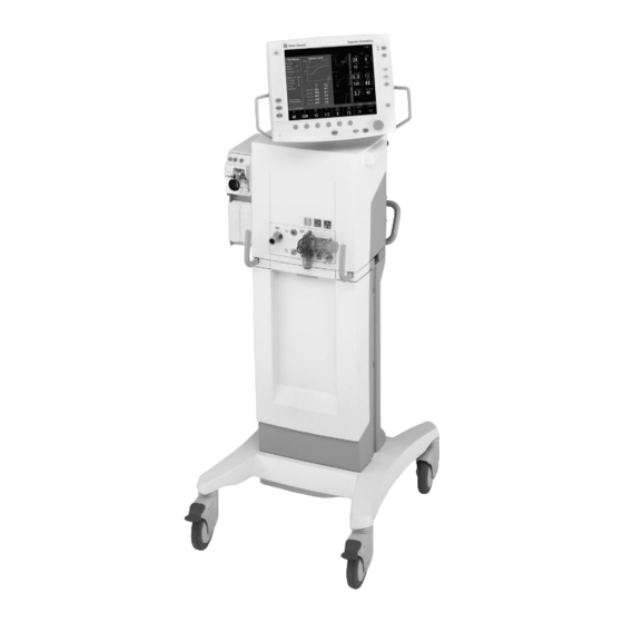
The Engström Carestation (EC) is a critical care ventilator that is flexible and physically adaptable to a variety of work environments. It has an intuitive user interface that is common to many Datex-Ohmeda products. A wide selection of performance options gives the user full control of the system configuration.
-
Page 16
Engström Carestation The system is designed for facility use, including within-facility transport, and should only be used under the orders of a clinician. It is designed to be operated on medical-grade gases only and should never be connected to gasses that do not meet the medical-grade requirements listed in Appendix A. The Engström Carestation consists of three main components: a display, a ventilator unit, and an optional module bay. -
Page 17: Ventilator Overview
1 Introduction 1.5 Ventilator overview 8 9 10 11 1. Module bay (optional) 10. Expiratory inlet 2. Ventilator lock [locks Ventilator unit (item 6) to Cart (item 3)] 11. Expiratory flow sensor 3. Cart 12. Gas exhaust port 4. Caster 13.
-
Page 18
Engström Carestation 1. Display fan filter 2. Display connection 3. Module bay connection 4. AC mains inlet 5. System switch 6. Equipotential connector 7. Oxygen supply connection (pipeline) 8. Air supply connection (pipeline or compressor) 9. Module bay mounting thumbscrews 10. -
Page 19: Display Controls And Indicators
1 Introduction 1.6 Display controls and indicators Alarm LEDs The red and yellow LEDs indicate the priority of active alarms. Silence Alarm key Push to silence any active, silenceable high and medium priority alarms or to suspend any non-active high or medium priority alarms. Alarm audio is silenced or suspended for 120 seconds for Adult and Pediatric patient types, and for 30 seconds for Neonatal patient types.
-
Page 20: Ventilator Display
Engström Carestation 1.7 Ventilator display • Alarm silence symbol Displays the time remaining during an alarm silence or alarm suspend period. and countdown Alarm message fields Alarms will appear in order of priority. Refer to “Alarms and Troubleshooting” for more information on alarm behavior.
-
Page 21
1 Introduction When a menu key is selected the waveform fields start at the right edge of the menu. The entire waveform is always displayed. 1. Menu 2. Waveform fields Figure 1-6 • Menu view 1505-1018-000 08/07… -
Page 22: Using Menus
Engström Carestation 1.7.1 Using menus Push a menu key to display the corresponding menu. Use the ComWheel to navigate through the menu. Xxxxxx Xxxxxx 1. Menu title 2. Present selection 3. Adjustment window 4. Indicates submenu 5. Short instructions 6. Menu selections Figure 1-7 •…
-
Page 23: Symbols Used In The Manual Or On The Equipment
1.8 Symbols used in the manual or on the equipment Symbols replace words on the equipment, on the display, or in Datex-Ohmeda manuals. Warnings and Cautions tell about the dangerous conditions that can occur if the instructions in the manual are not followed.
-
Page 24
Engström Carestation Pneumatic inlet Pneumatic outlet Electrical input Electrical output Inspiratory port Expiratory port Electrical testing certification Inspiratory breath identifier Serial port Module data indicator Module bay port Electronic micropump nebulizer Auxiliary pressure port Display signal input/output No battery/battery failure Battery in use. -
Page 25
1 Introduction Pump Heavy object USB port Ethernet connection Network ID connection (Datex-Ohmeda proprietary port) Í Autoclavable Not autoclavable 134°C Authorized representative in the Systems with this mark agree with European Community the European Council Directive (93/42/EEC) for Medical Devices… -
Page 26
Engström Carestation Indicates that the waste of electrical and electronic equipment must not be disposed as unsorted municipal waste and must be collected separately. Please contact an authorized representative of the manufacturer for information concerning the decommissioning of equipment. 1-14 08/07 1505-1018-000… -
Page 27: Theory Of Operation
2 Theory of Operation In this section 2.1 Pneumatic Operation …………2-2 2.1.1 Primary Gas Inlet .
-
Page 28: Pneumatic Operation
Engström Carestation 2.1 Pneumatic Operation For a complete diagram of the pneumatic system, refer to Figure 11-3, «Vent Engine manifold flow diagram» in Section11. The EC requires medical-grade oxygen (O ) and medical-grade Air sources ranging from 2.4 to 6.5 bar (35 to 94 psi). Refer to Appendix For additional information regarding medical-grade gasses.
-
Page 29: Primary Gas Inlet
2 Theory of Operation 2.1.1 Primary Gas Inlet Compressed gas enters the EC through an inlet fitting {2} that is particular to the institution’s supply system. The gas is filtered through a 2-micron particulate filter {3} and then a 0.5-micron coalescing particulate filter {3a} as it enters the ventilator’s “pneumatic engine”…
-
Page 30
Engström Carestation Downstream from the check valve is a 172 kPa (25 psi) pressure regulator {6}. (The regulator is a non-relieving type that does not bleed gas into the ventilator’s enclosure.) The regulator ensures a constant pressure supply to the flow valve {8}. The regulated supply is flow rate dependant, which is compensated for in the flow valve’s on-site calibration. -
Page 31
2 Theory of Operation Downstream of the flow sensor is a flow valve {8} that meters flows from approximately 0.05 l/min (leakage level) to a full flow value of 160 l/min. The valve is a normally- closed proportional solenoid that is powered by a current feedback loop. -
Page 32
Engström Carestation Following the two individual flow valves is the total flow sensor {10}. This sensor is the same type as the individual flow sensors and is used to measure the combined inspiratory flow being dispensed from the system. Using the known mixture composition along with atmospheric pressure and gas temperature information, mass-flow data from the sensor is converted to delivered volumetric flow towards the patient. -
Page 33
2 Theory of Operation Following the total flow sensor are the free-breathing check valve {11} and the inspiratory effort valve {12}. During normal operation, the inspiratory effort valve is open, allowing the free-breathing check valve to admit flow if the patient draws a significant amount of inspiratory pressure, causing the airway pressure to become more negative than -0.5 cm H O. -
Page 34
Engström Carestation As a safety measure, a relief valve {14}, located downstream from the O sensor, can be energized to vent the full flow rate of the inspiratory delivery side of the system. If an overpressure condition is detected, the valve can be opened by either of the EC’s two control processors. -
Page 35: Expiratory Circuit
2 Theory of Operation 2.1.2 Expiratory circuit At the expiratory side of the ventilator, a solenoid powered exhalation valve {16} controls exhaust from the breathing circuit. The valve contains an elastomer diaphragm that is held against a rigid seat by a solenoid (voice coil) driven piston.
-
Page 36
Engström Carestation electrically act as variable resistors in each of the bridges. The sensors hold a constant temperature at all times as they contain a linear resistance change with temperature. The Neonatal Flow sensor is connected to the Ventilator Monitoring Board (VMB) through the Motherboard via Port 1 and a 2 meter long shielded cable, detachable at both ends. -
Page 37: Associated Circuits
2 Theory of Operation 2.1.3 Associated circuits Associated with the inspiratory and expiratory pressure transducers are two “zeroing” solenoid valves {21} and {22}. These valves are used to disconnect the pressure transducers from circuit pressure and vent them to atmosphere during zero bias calibration.
-
Page 38: Electrical Operation
Engström Carestation 2.2 Electrical Operation For a complete diagram of the electrical system, refer to Figure 11-5, «Electrical architecture» in Section11. The EC includes 5 major processor control boards: • Display Unit: DU (1009-8289-000) or HPDU (1009-5933-000) • Ventilator Control Board (1505-5500-000) •…
-
Page 39: Software Requirements
2 Theory of Operation 2.2.2 Software The DU uses a PCMCIA interface to handle software upgrades and to load the diagnostics Service Application. The DU is compatible with system software requirements versions 3.X and lower. The HPDU uses a Compact Flash interface to handle software upgrades and to load the diagnostics Service Application.
-
Page 40: System Connections
Engström Carestation 2.3 System Connections 2.3.1 Display Unit The DU accommodates the following connections: • Display connection (1 1 1 1 ). • DIS connector — supports D-O Device Interface Solution (DIS) (2 2 2 2 ). • Network connection — Standard Ethernet port for network connectivity (3 3 3 3 ). •…
-
Page 41: Display Unit
2 Theory of Operation 2.3.2 High Performance The HPDU accommodates the following connections: Display Unit • Display connection (1 1 1 1 ). • Future expansion(2 2 2 2 ). • Future expansion (3 3 3 3 ). • Future expansion (4 4 4 4 ). •…
-
Page 42: Communication Channels
The DU communicates to the remainder of the EC system through the Motherboard using 5 digital channels. channels [1] A 500 Kbaud, RS-485 interface (Mod Bus: Datex-Ohmeda proprietary module communication protocol), to external monitoring modules. This link runs through the Monitoring Module Power supply board which forms the physical interface to the M-Gas (and ultimately other) monitoring modules.
-
Page 43
2 Theory of Operation Display Unit RS-232 38.4 Kbaud PCMCIA (2) RS-232 Serial External I/O Display Unit CPU RS-422 38.4 Kbaud RS-422 38.4 Kbaud Memory Card Mod Bus, RS-485 500 Kbaud Color LCD DU Controls Module Bay EV Chassis E & M-Gas Intel 196 Mod Bus, RS-485… -
Page 44: Ventilator Control Board — Vcb
Notes 2.3.4 Ventilator The VCB is a Motorola Coldfire V4 CPU powered assembly that: Control Board — •collects information from all EC system sensors (some indirectly from the VMB), •and controls all actuators necessary to effect ventilation delivery. he VCB computes and supplies all ventilation sensor monitoring data for display on the DU. If there are alarms to be generated based on this monitoring data, the VCB notifies the DU to post the appropriate alarm message and audio sequence.
-
Page 45
2 Theory of Operation For further details, refer to Figure 11-13, «VCB block diagram» in Section11. Vent Control Board 1 MB V Checks SRAM Piezo-Electric Coldfire Nebulizer V4 CPU Neb Board 8 MB Watchdog Flash Circuit Power Exhal Valve Flow Valve Power Drive w/ V &… -
Page 46: Ventilator Monitoring Board — Vmb
Engström Carestation 2.3.5 Ventilator The Engström Carestation can use one of two Ventilator Monitoring Boards: Monitoring Board — • Original VMB, PN 1505-5501-000 (Original VMB units do not support the Neonatal option) o o o o r r r r •…
-
Page 47
2 Theory of Operation Nurse Call Nurse Call functionality is supported on units with Serial Numbers greater than CBK00356 and units updated with Motherboard M1053184 and VMB M1052980. Port 4 (15 pin) may be used to output alarm signals to a nurse call system. The ventilator will signal an alarm with a normally open or normally closed signal. -
Page 48
Engström Carestation Vent Monitor Board Insp Effort Insp Maneuver Circuit Power Valve Atmel Valve Drive ATmega128 Safety Insp Effort Valve Control Relief Valve Exh Valve Closed Safety Valve Drive Air Pipeline P UARTS Safety Valve On/Off O2 Pipeline P Exh Valve On/Off RS-422 VMB — DU Data I/O Exp Flow… -
Page 49: Power Management Board — Pmb
2 Theory of Operation 2.3.6 Power The PMB is based on an Atmel Atmega 128 CPU. The PMB performs power selection between power sources in the following order: Management • AC power mains, Board – PMB • Internal battery. The PMB regulates the 24 Vdc power supply output down to raw 16 V and 12.5 V power rails that are used throughout the system (all boards locally regulate from these power rails).
-
Page 50: Motherboard (Backplane)
Engström Carestation 2.3.8 Motherboard The Engström Carestation can use one of two Motherboards: (backplane) • Original Motherboard — 1505-5504 (Port 2 — 15 pin) o o o o r r r r • Current Motherboard — M1053184 (Port 2 — 9 pin) N N N N o o o o t t t t e e e e : : : : If replacement of the original Motherboard with a current Motherboard is required, it is necessary to replace the original VMB (1505-5501-000) with the current VMB (M1052980).
-
Page 51: Monitoring Interface Board — Monitoring Module Bays
2 Theory of Operation 2.3.9 Monitoring The EC accommodates an optional four-bay module assembly that supports compatible Datex-Ohmeda M-series modules. Interface Board – Monitoring The assembly includes a Monitoring Interface Board (MIB) that communicates with the DU through the Mod Bus connector. The MIB includes circuitry that regulates the raw Module Bays 16 V power down to +15 V (unregulated), ±15 V (regulated), and +5 V levels required by…
-
Page 52
Engström Carestation 2-26 08/07 1505-1018-000… -
Page 53: Checkout Procedure
3 Checkout Procedure In this section 3.1 Inspect the system …………3-2 3.2 Automated Checkout .
-
Page 54: Inspect The System
Engström Carestation 3.1 Inspect the system Before testing the system, ensure that: • The equipment is not damaged. • Components are correctly attached. • Pipeline gas supplies are connected. • The casters are not loose and the brakes are set and prevent movement. •…
-
Page 55: Backlight Test
3 Checkout Procedure 5. Select Previous Menu. Checkout includes the following checks: • Paw Transducer Check • Barometric Pressure Check • Relief Valve Check • Exhalation Valve Check • Expiratory Flow Sensor Check • Air Flow Sensor Check • O2 Flow Sensor Check •…
-
Page 56: Electrical Safety Tests
3.5 Electrical safety tests w w w w WARNING Make sure the system is completely assembled and that the power cords are connected as illustrated in Section 10.15. Make sure all accessory devices are connected to electrical outlets. 1. Connect an approved test device (for example: UL, CSA, or AAMI) and verify that the leakage current is less than: Voltage Max.
-
Page 57: Installation And Service Menus
4 Installation and Service Menus In this section 4.1 Service and Installation menu structure ……..4-2 4.2 Install/Service Menu (Super User) .
-
Page 58: Service And Installation Menu Structure
Engström Carestation 4.1 Service and Installation menu structure This section describes the Service level functions that are part of the main software installed in the ventilator. Section 8, “Service Diagnostics and Software Download,” covers a separate service application that loads from a PCMCIA card and is used to download system software and run service diagnostics and other service tests.
-
Page 59: Install/Service Menu (Super User)
4 Installation and Service Menus 4.2 Install/Service Menu (Super User) Use the super-user password to access the Install/Service menu: “23-17-21”. Menu Item Message text Comments Configure graphical trend pages. Refer to section 4.2.1 Trends Setup Display Settings Set colors, units of parameter, and Refer to section 4.2.2 time and date.
-
Page 60: Trends Setup
Engström Carestation 4.2.1 Trends Setup Menu Item Message text Values Default Trend Change default trend type: Num (default), graphical, numerical, or settings. Graph, or Set Graphical Trends Configure graphical trend pages Pages 1-5 Previous Menu Return to previous menu. Graphical Trends Menu Item Message text Page 1…
-
Page 61: Display Settings
4 Installation and Service Menus 4.2.2 Display Settings The Display Settings menu can be accessed here in the super-user level to change individual preferences, or if required during installation, in the service level Installation menu. Menu Item Message text Values Colors Set colors of parameters.
-
Page 62
Engström Carestation Units Menu Menu Item Message text Values Change Paw unit kPa, cmH2O Flow Change Flow unit l/min or l/s Change CO2 unit %, kPa, or mmHg Height Change height unit cm or in Weight Change weight unit kg or lb Energy Expenditure Change EE unit kcal/d or kJ/d… -
Page 63: Ventilator Settings
4 Installation and Service Menus 4.2.3 Ventilator Settings Menu Item Message text Values Timing Change timing setting: I:E, Tinsp, or I:E, Tinsp, Tpause Tpause. Tpause is only available when Flow is set to On. Flow Select to use Flow settings or Insp On, Off Pause.
-
Page 64: Defaults
Engström Carestation 4.2.5 Defaults Menu Item Message text Comments Push ComWheel to scroll default Scroll Settings settings. Default Type Select default patient type. The selected type (Adult, Pediatric, or Neonatal) determines the Patient Type in the Select Patient Menu on power up. The corresponding Adult, Pediatric, Neonatal, or facility defaults are displayed for the settings on power up.
-
Page 65
4 Installation and Service Menus Menu Item Message text Comments Save current settings as facility The default selection is No. Common Save Current defaults. values in the saved defaults are overridden if another ventilation mode is set up and saved. Save factory settings as facility The default selection is No. -
Page 66: Factory Defaults
Engström Carestation 4.2.6 Factory Defaults The following table lists the factory defaults for parameters and alarm limits: Setting Adult Pediatric Neonatal Backup Defaults Vent Mode BiLevel BiLevel Current FiO2 setting FiO2 10 cmH2O (10 mbar, 1.0 7 cmH2O (7 mbar, 0.7 5 cm H2O (5 mbar, 0.5 10 cmH2O (10 mbar, 1.0 Pinsp…
-
Page 67: Calibration Menu
4 Installation and Service Menus 4.3 Calibration menu Menu Item Message text Comments Start O2 Flow Control Valve Select Start Calibration. O2 FCV calibration and leak test. Open inspiratory port to atmosphere. Start 02 Flow Control Valve calibration. Start Air Flow Control Valve Select Start Calibration.
-
Page 68: Service Menu
Notes 4.4 Service menu Use the service-level password to access the Service menu: “34-22-14.” Whenever service menu is entered, “Enter Service dd-mmm-yyyy hh:mm:ss” is recorded in the Event log. Menu Item Message text Configuration Set language, altitude and units. Enable software options. Options Key Display software options.
-
Page 69: Configuration
4 Installation and Service Menus 4.4.1 Configuration Menu Item Message text Values Comments Select decimal 0.01, 0 01 or 0,01 Default: 0.01 Decimal Marker delineator. Language Select language for Chinese (simplified) Default: English screen. Czech Danish Dutch English Finnish French German Greek Hungarian…
-
Page 70: Options Key
Engström Carestation 4.4.2 Options Key Menu Item Message text Current Key Enter key code to enable options. Enter first value of key-code. Entry 1 Enter second value of key-code. Entry 2 Entry 3 Enter third value of key-code. Enter fourth value of key-code. Entry 4 Enter fifth value of key-code.
-
Page 71: Copy Configuration
4 Installation and Service Menus 4.4.5 Copy Configuration Menu Item Message text Values Comments Save Configuration and <blank>, Fail, or OK. Saves all settings Save to Card defaults to card. that are not hardware The field is blank until the dependent, including data has either been facility defaults,…
-
Page 72: Service Log Menu
Engström Carestation 4.4.6 Service Log The Service log menu is a organized listing of stored events. menu Menu Item Message text Scroll through newest entries. Scroll Recent Show error history. Error Log Show event history. Event Log Alarm Log Show alarm history. SW HW versions Show system information.
-
Page 73: Software/Hardware Version Menu
4 Installation and Service Menus 4.4.7 Software/ Turn the ComWheel to scroll through the list box. Hardware Push the ComWheel to return to the Service menu. version menu System Information X=Number, A, B, C = letter menu SW HW version System Information: Running Hours: XXXXX Software Release: XX.XX…
-
Page 74: Resetting Feature Option Key Codes
Engström Carestation 4.4.8 Resetting 1. Power up the Engström Carestation and select Service Menu -Options List. feature option key 2. Record the available options that are «On». codes 3. Power down the ventilator. 4. Perform the software download per TRM Section 8.4, «Download New». 5.
-
Page 75: Service Tests And Calibration
5 Service Tests and Calibration WARNING After adjustments and calibration are completed, always perform the checkout procedure. Refer to Section 3 of this manual. In this section 5.1 Calibration (super-user) ……….. . .5-2 5.1.1 Calibration procedure .
-
Page 76: Calibration (Super-User)
Engström Carestation 5.1 Calibration (super-user) The EC ventilator includes integrated software that allows a qualified user to periodically calibrate the O flow valve, the Air flow valves, and the Exhalation valve. At a minimum, these calibrations should be completed every 6 months, whenever performance is questioned, or when associated components are serviced or replaced.
-
Page 77: Calibration Procedure
5 Service Tests and Calibration 5.1.1 Calibration 1. If present, disconnect the patient circuit from the inspiratory port (open to procedure atmosphere). 2. Access the Calibration menu. • In the standby mode, push the System Setup key. • On the System Setup menu, select Install/Service (23-17-21). •…
-
Page 78: Service Level Tests And Calibration
Engström Carestation 5.2 Service level tests and calibration The service level tests require the Windows based service application as described in Section 8.5, “EC Service Application (PC based)” . Note After completing the Service level test and calibrations, perform the Valve calibrations in Section 5.1.1.
-
Page 79: Vent Engine Debris Clean-Out
5 Service Tests and Calibration 5.2.3 Vent engine debris This procedure is needed only if: clean-out • The pneumatic system within the vent engine was serviced; that is, components were replaced or removed for evaluation. • A gas inlet filter was replaced. Clean-out procedure 1.
-
Page 80: Regulator Output Pressure Test
Engström Carestation 5.2.4 Regulator output pressure test Important The regulator output pressure should be checked during battery replacement intervals or whenever the unit is already opened for other reasons. Air regulator 1. Remove the plug from the Air regulator outlet test port. 2.
-
Page 81
5 Service Tests and Calibration 30 mm Male Cone Pneumatic Exhalation Resistor Flow Sensor Expiratory Zero Flow Valve High Pressure Valve Transducer Flow Regulator Pneumatic Sensor Exhalation Resistor 25 psi Test Valve 172 kPa Port Expiratory Pressure Inlet Check Filter Standard Primary Valv… -
Page 82: Vent Engine Leak Test (Low Pressure)
Engström Carestation 5.2.5 Vent engine leak There are two low pressure leak tests to perform: P1 and P2. test (low pressure) Low P1 Test 1. Verify that both shut-off valves are closed. 2. On the VCB screen: • Energize (;) the Auxiliary Pressure Purge valve. •…
-
Page 83
5 Service Tests and Calibration 30 mm Male Cone Pneumatic Exhalation Resistor Flow Sensor Expiratory Zero Valve High Pressure Transducer Flow Regulator Pneumatic Sensor Exhalation 25 psi Resistor Flow Test Valve 172 kPa Port Valve Expiratory Pressure Inlet Check Primary Filter Standard Valve… -
Page 84
Engström Carestation Low P2 Test 1. Verify that both shut-off valves are closed. 2. On the VCB screen: • Energize (;) the Effort Valve Energized valve. • Energize (;) the Auxiliary Pressure Purge valve. • Verify that the Air Flow Valve, O2 Flow Valve and the Exhalation Flow Valve are energized (;). -
Page 85
5 Service Tests and Calibration 30 mm Male Cone Pneumatic Exhalation Resistor Flow Sensor Expiratory Zero Valve High Pressure Transducer Flow Regulator Pneumatic Sensor Exhalation 25 psi Resistor Flow Test Valve 172 kPa Port Valve Expiratory Pressure Inlet Check Primary Filter Standard Valve… -
Page 86: Vent Engine Leak Test (High O Pressure)
Engström Carestation 5.2.6 Vent engine Note: The high O2 pressure leak test will not start if the O2 supply pressure is 35 psig or below. leak test (high O pressure) 1. Verify that the inspiratory outlet is open to atmosphere (not plugged). 2.
-
Page 87
5 Service Tests and Calibration 30 mm Male Cone Pneumatic Exhalation Resistor Flow Sensor Expiratory Zero Valve High Pressure Transducer Flow Regulator Pneumatic Sensor Exhalation 25 psi Resistor Flow Test Valve 172 kPa Port Valve Expiratory Pressure Inlet Check Primary Filter Standard Valve… -
Page 88: Vent Engine Leak Test (High Air Pressure)
Engström Carestation 5.2.7 Vent engine leak Note: The high Air pressure leak test will not start if the Air supply pressure is 35 psig or below. test (high Air pressure) 1. Verify that the INSPiratory outlet is open to atmosphere (not plugged). 2.
-
Page 89
5 Service Tests and Calibration 30 mm Male Cone Pneumatic Exhalation Resistor Flow Sensor Expiratory Zero Flow Valve High Pressure Valve Transducer Flow Regulator Pneumatic Sensor Exhalation 25 psi Resistor Test Valve 172 kPa Port Expiratory Pressure Inlet Check Primary Filter Standard Valv… -
Page 90: Calibrate Airway Pressure Transducer Zero And Span
Engström Carestation 5.2.8 Calibrate This procedure calibrates the Inspiratory, Expiratory, and Auxiliary pressure transducers. airway pressure transducer Note: If Air is not available, the O supply can be used to calibrate the pressure transducers. The Service Application senses which supply is available and, in step 5, Zero and Span activates the corresponding flow valve.
-
Page 91
5 Service Tests and Calibration 30 mm Male Cone Pneumatic Exhalation Resistor Flow Sensor Expiratory Zero Valve High Pressure Transducer Flow Regulator Pneumatic Sensor Exhalation Resistor 25 psi Flow Test Valve 172 kPa Port Valve Expiratory Pressure Inlet Check Filter Standard Primary Valv… -
Page 92: Verify Operation Of Free-Breathing Valve
Engström Carestation 5.2.9 Verify 1. Ensure both manual shut-off valves are closed. operation of free- 2. Connect a negative pressure squeeze bulb to the INSPiratory outlet. breathing valve 3. Fully depress the bulb a minimum of 10 times. 4. On the VCB screen: •…
-
Page 93
5 Service Tests and Calibration 30 mm Male Cone Pneumatic Exhalation Resistor Flow Sensor Expiratory Zero Flow Valve High Pressure Valve Transducer Flow Regulator Pneumatic Sensor Exhalation 25 psi Resistor Test Valve 172 kPa Port Expiratory Pressure Inlet Check Primary Filter Standard Valv… -
Page 94: Verify Operation Of Inspiratory Effort Valve
Engström Carestation 5.2.10 Verify 1. Ensure both manual shut-off valves are closed. operation of 2. On the VCB screen: inspiratory effort • Energize (;) the Auxiliary Pressure Purge valve. valve • Energize (close) the inspiratory effort valve (; Effort Valve Energized). •…
-
Page 95
5 Service Tests and Calibration 30 mm Male Cone Pneumatic Exhalation Resistor Flow Sensor Expiratory Zero Valve High Pressure Transducer Flow Regulator Pneumatic Sensor Exhalation 25 psi Flow Resistor Test Valve 172 kPa Port Valve Expiratory Pressure Inlet Check Primary Filter Standard Valv… -
Page 96: Verify Operation Of Auxiliary Pressure Relief Valve
Engström Carestation 5.2.11 Verify 1. Connect a manometer to the auxiliary pressure port (Paux) using a tee fitting and a operation of short piece of 3-mm (1/8 inch) tubing. auxiliary pressure 2. Open the manual Air shut-off valve. relief valve 3.
-
Page 97
5 Service Tests and Calibration 30 mm Male Cone Pneumatic Exhalation Resistor Flow Sensor Expiratory Zero Flow Valve High Pressure Valve Transducer Flow Regulator Pneumatic Sensor Exhalation 25 psi Resistor Test Valve 172 kPa Port Expiratory Pressure Inlet Check Primary Filter Standard Valv… -
Page 98: Mechanical Over-Pressure Valve Test
Notes 5.2.12 Mechanical 1. Verify that the ventilator passes the low pressure leak test (Section 5.2.5). over-pressure 2. Turn the ventilator off. valve test 3. Using a syringe, inject 60 ml of air into the ventilator through the INSPiratory port. 4.
-
Page 99
5 Service Tests and Calibration 30 mm Male Cone Pneumatic Exhalation Resistor Flow Sensor Expiratory Zero Flow Valve High Pressure Valve Transducer Flow Regulator Pneumatic Sensor Exhalation Resistor 25 psi Test Valve 172 kPa Port Expiratory Pressure Inlet Check Filter Standard Primary Valv… -
Page 100
Engström Carestation 5-26 08/07 1505-1018-000… -
Page 101: Installation And Maintenance
6 Installation and Maintenance In this section This section covers the regular maintenance procedures (minimum requirements) needed to make sure that the Engström Carestation operates to specifications. 6.1 Engström Carestation Installation Checklist ……..6-2 6.2 Engström Carestation Planned Maintenance .
-
Page 102: Engström Carestation Installation Checklist
Engström Carestation 6.1 Engström Carestation Installation Checklist Serial Number: Date: (YY/MM/DD) Hospital: Performed by: Note: Check for shipping damage, if any is noted, take photos and notify the shipping carrer. † 1. Unpack and assemble the Engström Carestation. Refer to Section 3. †…
-
Page 103
6 Maintenance † b. Options List (TRM — Section 4.4.3) • Verify that the factory installed ventilation options match the configuration purchased with the machine. † c. Copy Configuration menu (TRM — Section 4.4.5) • Can be used to copy a configuration to a Compact Flash card and then copy the configuration to additional machines. -
Page 104: Engström Carestation Planned Maintenance
Notes 6.2 Engström Carestation Planned Maintenance Serial Number: Date: (YY/MM/DD) Hospital: Performed by: † 12 months † 24 month † 48 month † ______________________ 6.2.1 Every twelve Perform the following steps every 12 months. For details, refer to the sections listed. (12) months †…
-
Page 105: Junair Evair03 Compressor Maintenance (Model Of302-1.5Dsa)
6 Maintenance 6.3 JunAir EVair03 Compressor Maintenance (Model OF302-1.5DSA) Serial Number: Date: (YY/MM/DD) Hospital: Performed by: † 12 months † 24 month † 48 month † ______________________ 6.3.1 Every twelve Perform the following steps every 12 months. (12) months Refer to the JunAir EVair03 Compressor Technical Reference manual (TRM) — 6189655 for additional information.
-
Page 106: Every 10, 000 Hours
Engström Carestation 6.3.2 Every 10, 000 hours In addition to the 12-month requirements, replace the following parts every 10,000 hours. All parts should be replaced before performing the checks, tests, and calibrations. † 1. Install 10,000 Hour Kit after 10,000 hours of operation (Check hour meter).
-
Page 107: Cleaning And Sterilizing Agents
6 Maintenance 6.4 Cleaning and sterilizing agents WARNING The following cleaning/disinfection agents have been validated for material compatibility only. The effectiveness of sterilization with these agents has not been validated. Mild Ethyl Autoclave at detergent Sporox II Cidex NU-CIDEX CIDEX OPA 134°…
-
Page 108: Battery Capacity Test
Engström Carestation 6.5 Battery capacity test Although replacement of the backup batteries is recommended at the end of 4 years, batteries that pass the capacity test can be considered viable for battery backup of the system for up to 6 years at the discretion of the hospital. Before testing the batteries, ensure that the PMB Diagnostics screen shows that the battery is fully charged.
-
Page 109: Troubleshooting
7 Troubleshooting In this section 7.1 Troubleshooting Checkout Failures ……….7-2 7.1.1 Paw transducer check .
-
Page 110: Troubleshooting Checkout Failures
Engström Carestation 7.1 Troubleshooting Checkout Failures Note: If the Automated Checkout (Section 3.2) results in failures, refer to the following sections to troubleshoot a specific failure. Use EC Service Application PC based (Section 8.5) while running all tests . To file a quality report or request technical assistance regarding a checkout failure, create and include a Checkout log using the EC Service Application.
-
Page 111: Barometric Pressure Test
7 Troubleshooting Paw insp Paw exp are not within 4 cmH O when pressurized to 34 cm H Test results indicate Fail but no alarm message is displayed. • Use EC Service Application PC based (Section 8.5) to facilitate problem isolation.
-
Page 112: Safety Valve Relief And Back Pressure
Engström Carestation 7.1.4 Safety valve The Safety Valve Relief test checks the ability of the Safety Relief Valve to relieve all patient pressure on demand. Failures include: relief and back pressure 1. Set the Air (O2) flow valve to 3 lpm. If at least 30 cmH2O cannot be achieved, the test will indicate Fail but no alarm message is displayed.
-
Page 113: Exhalation Valve Calibration Check
7 Troubleshooting 7.1.5 Exhalation valve The Exhalation Valve Calibration check sets flow at 4 l/min as measured by the total flow sensor and the expiratory valve to 34 cmH2O. Once stable, it calibration check opens the Expiratory Valve and verifies that the exp Paw is less than 2 cmH2O within 250 ms.
-
Page 114: Measure Breathing Circuit Resistance
Engström Carestation 7.1.7 Measure breathing The breathing circuit resistance is calculated from the amount of resistance created when 60 l/min is flowing through the circuit. It is calculated and circuit resistance displayed on the bottom of the screen. It represents the resistance of 1/2 of the breathing circuit.
-
Page 115: Neonatal Flow Sensor Calibration Check
7 Troubleshooting 7.1.11 Neonatal flow This test verifies the accuracy of both the inspiratory and expiratory flow sensor circuits in the Neonatal Flow Sensor at 20 l/min. sensor calibration check 1. During this stage the circuit is occluded. The flow is set to 4 l/min and the flow sensor should indicate 0 l/min.
-
Page 116: Troubleshooting Vent Engine Leaks
Engström Carestation 7.2 Troubleshooting Vent Engine Leaks Note: Use the EC Service Application PC based (Section 8.5) while running all tests. • Refer to Section 7.2.1 if the vent engine leak test fails (Section 5.2.5) by either being unable to build 70 cmH2O pressure or if the leak rate exceeds 10 ml/min.
-
Page 117
7 Troubleshooting 30 mm Male Cone Pneumatic Exhalation Resistor Flow Sensor Expiratory Zero Flow Valve High Pressure Valve Transducer Flow Regulator Pneumatic Sensor Exhalation Resistor 25 psi Test Valve 172 kPa Port Expiratory Pressure Inlet Check Filter Standard Primary Valve Inspiratory Pressure Inlet Inspiratory Zero… -
Page 118
Engström Carestation 5. Open only the O flow valve by checking the O2 Flow Valve box (verify that 60000 DAC counts are set). 6. Repeat the Vent Engine Leak Test. • If the test fails, check the individual components in the O Flow path. -
Page 119
7 Troubleshooting 30 mm Male Cone Pneumatic Exhalation Resistor Flow Sensor Expiratory Zero Flow Valve High Pressure Valve Transducer Flow Regulator Pneumatic Sensor Exhalation 25 psi Resistor Test Valve 172 kPa Port Expiratory Pressure Inlet Check Filter Primary Valve Inspiratory Pressure Inlet Inspiratory Zero Total Flow… -
Page 120: Auxiliary And Expiratory Pressure Circuit Leaks
Engström Carestation 7.2.2 Auxiliary and If the vent engine leak test (Section 5.2.5) fails at step 5, the following steps will help to locate the possible leak locations. Flow in the Auxiliary and expiratory pressure Expiratory pressure circuits is restricted, therefore failure to build pressure circuit leaks may not cause the leak test to fail, and may not affect checkout, or system while in use.
-
Page 121
7 Troubleshooting If the Auxiliary pressure is lower than the Inspiratory pressure: 1. Remove the restrictor and re-install the restrictor access cover. Repeat the test. a. If pressures equal, install a new restrictor and repeat the test. b. If not, or if failure occurs with new restrictor, continue. 2. -
Page 122: Troubleshooting Startup Screen (Post) Messages
Engström Carestation 7.3 Troubleshooting Startup Screen (POST) messages If the EC system encounters a problem at startup to where it cannot initiate system software, a BIOS error message indicating the failure will be displayed. Message What it indicates Troubleshooting Action Required ***NOTE: This indicates an illegal value in the Set the system date and time manually to the…
-
Page 123: Troubleshooting Startup Screen (Post) Messages — For Hpdu
7 Troubleshooting 7.4 Troubleshooting Startup Screen (POST) messages — for HPDU If the EC system encounters a problem at startup to where it cannot initiate system software, a BIOS error message indicating the failure will be displayed. Message What it indicates Troubleshooting Action Required ***ERROR: This indicates a hardware failure.
-
Page 124
Engström Carestation 7-16 08/07 1505-1018-000… -
Page 125: Troubleshooting The Display — Hpdu
7 Troubleshooting 7.5 Troubleshooting the Display — HPDU Symptom Resolution System will not boot from external Compact Flash 1. Verify that the Compact Flash card is properly inserted. card during software installation process 2. Insert a backup Compact Flash card. 3.
-
Page 126: Alarm Message Troubleshooting Chart
Engström Carestation 7.6 Alarm message troubleshooting chart Note: Whenever “Check/replace harness” is indicated, ensure that all terminals are fully inserted into the connector body window and that all wires are properly crimped. Troubleshooting guidelines are listed in order of probability. The entire list does not need to be carried out if the problem is resolved.
-
Page 127
7 Troubleshooting Alarm message Alarm ID Priority Alarm Condition Special Behavior/Comments • Action/Troubleshooting -none- Neo Exh Flow Sensor High (Exh TVexp — Neo TVexp) > (0.3* Neo Comparison TVexp) or 30 mL whichever is greater for 6 consecutive breaths. • Calibrate neo flow sensor. •… -
Page 128
Engström Carestation Alarm message Alarm ID Priority Alarm Condition Special Behavior/Comments • Action/Troubleshooting Temp High High Total flow sensor temperature > 48°C Switch to 100% O2. Air temp high Air is turned off regardless of Flow Wave: other alarm conditions (for O2 only example, O2 Supply Low). -
Page 129
7 Troubleshooting Alarm message Alarm ID Priority Alarm Condition Special Behavior/Comments • Action/Troubleshooting FRC invalid An FRC measurement was started for Cannot calculate FRC or PEEP Inview, but unable to be completed within the last 5 seconds. • Check end tital CO2 reading. •… -
Page 130
Engström Carestation Alarm message Alarm ID Priority Alarm Condition Special Behavior/Comments • Action/Troubleshooting Nebulizer not Nebulizer disconnected while Connect Connected nebulization procedure is running. nebulizer • Re-connect Nebulizer. • Replace Nebulizer cable. • Replace Nebulizer head. • Replace Nebulizer board. Front Panel Com Fail High Display CPU board fails to send life tick… -
Page 131
7 Troubleshooting Alarm message Alarm ID Priority Alarm Condition Special Behavior/Comments • Action/Troubleshooting Air Flow Sensor Medium Loss of communication with Air Flow Use Open Loop valve mixture FiO2 control error Communications Sensor. control. Failure Return to closed loop volume delivery control when cleared. -
Page 132
Engström Carestation Alarm message Alarm ID Priority Alarm Condition Special Behavior/Comments • Action/Troubleshooting Total Flow Temperature Out of range total temperature sensor Use air flow temperature for Mixed gas temp Sensor Failure data or loss of communication. total flow sensor calculations, sensor error including alarms. -
Page 133
7 Troubleshooting Alarm message Alarm ID Priority Alarm Condition Special Behavior/Comments • Action/Troubleshooting Neo Flow Sensor Off Medium Neo flow sensor turned off in neo flow Neo flow sensor sensor setup menu. • Turn on neo flow sensor. Remove airway Neo module not Any MGAS module is installed in the compatible… -
Page 134
Engström Carestation Alarm message Alarm ID Priority Alarm Condition Special Behavior/Comments • Action/Troubleshooting DU to PMB Com Error Medium Communications from the DU to the PMB assumes failed state and No battery -or- power controller cannot be established allows system to shutdown backup? PMB to DU Com Error for 10 seconds. -
Page 135
7 Troubleshooting Alarm message Alarm ID Priority Alarm Condition Special Behavior/Comments • Action/Troubleshooting Battery Missing Medium Any battery voltage is between -1.0 Battery status indicator No battery and +1.0VDC. appears under clock. backup Refer to Section 8.1.3 for more information. •… -
Page 136
Engström Carestation Alarm message Alarm ID Priority Alarm Condition Special Behavior/Comments • Action/Troubleshooting No Supply Pressure High O2 supply pressure and air supply Continue 100% gas flow of No gas supply pressure < 24.3 psi for more than 0.5 whichever gas has the higher pressure seconds pressure value at the onset of… -
Page 137
7 Troubleshooting Alarm message Alarm ID Priority Alarm Condition Special Behavior/Comments • Action/Troubleshooting Low Internal Medium Mains power not available. On battery Battery – 30 Internal battery supply < 30 minutes calculated via battery discharge algorithm. Medium Mains power not available. System On battery Battery powered by internal battery for more… -
Page 138
Engström Carestation Alarm message Alarm ID Priority Alarm Condition Special Behavior/Comments • Action/Troubleshooting Standby Patient High Paw insp or Paw exp > 3 cmH2O when Non-silencable Patient Detection bias flow set to 3 l/min air or O2 (if Air Audible in Standby and connected? not available) and exhalation valve set Monitoring states. -
Page 139
7 Troubleshooting Alarm message Alarm ID Priority Alarm Condition Special Behavior/Comments • Action/Troubleshooting Barometric Pressure Out of range barometric pressure data. The EC will use the entered Pbaro sensor out Sensor Out of Range Range: 2163-4340 mV or 732-1196 altitude setting to determine of range cmH2O the calculated barometric… -
Page 140
Engström Carestation Alarm message Alarm ID Priority Alarm Condition Special Behavior/Comments • Action/Troubleshooting Paw Cross- Check High Paw exp – Paw insp > 10 cmH2O for Pressure sensor more than 100 ms failure • Verify Pexp port is not occluded. •… -
Page 141
7 Troubleshooting Alarm message Alarm ID Priority Alarm Condition Special Behavior/Comments • Action/Troubleshooting MGAS Inlet Filter MGAS communicates: Residue De-escalatable. Replace D-fend Residue >40 Sec buildup on the water trap membrane. The pump turns Off. CO2 or O2 wave: This decreases airflow. Normal Screen If a push is… -
Page 142
Notes Alarm message Alarm ID Priority Alarm Condition Special Behavior/Comments • Action/Troubleshooting Failed State DU to VCB Com Error Failed Proper communications from the DU to Run Backup Ventilation if in message: the VCB is not successfully completed Therapy. System failure. within 90 seconds after startup or Service required within a 10 second window after… -
Page 143
7 Troubleshooting Alarm message Alarm ID Priority Alarm Condition Special Behavior/Comments • Action/Troubleshooting Failed State Processor Reset Failed Sequential watchdogs cause a Vent Safe Operation. message: processor reset on either VCB or VMB. This requirement is intended System failure. to ensure that a SW or Service required watchdog reset (indicating loss of processor control) of… -
Page 144
Engström Carestation Alarm message Alarm ID Priority Alarm Condition Special Behavior/Comments • Action/Troubleshooting Failed State VMB to DU Com Error Failed Proper communications from the VMB Run Backup Ventilation if in message: to the DU is not successfully Therapy. System failure. completed within a 10 second window. -
Page 145
7 Troubleshooting Alarm message Alarm ID Priority Alarm Condition Special Behavior/Comments • Action/Troubleshooting Low Internal Battery – High Mains power not available. Internal System 20 Min battery supply < 20 minutes shutdown in <20 min. calculated via battery discharge algorithm. Low Internal Battery –… -
Page 146
Engström Carestation Alarm message Alarm ID Priority Alarm Condition Special Behavior/Comments • Action/Troubleshooting Total Flow Sensor High Out of range total flow sensor data Return to closed loop volume Volume delivery Communications -or- delivery control when cleared. error Failure Loss of communication. •… -
Page 147: Troubleshooting Service App Messages
7 Troubleshooting 7.7 Troubleshooting Service App messages The VCB Service App screen includes a Calibrations and Tests section (Section 8.6.5). This section includes a field “Calibration Running” that displays messages while a test is in progress. Some messages indicate that the test encountered a problem. Use the following table to help troubleshoot messages that result in a failed test or calibration.
-
Page 148
Engström Carestation Message in Reason Troubleshooting Calibration running” “ field Aux Span Counts: Value Auxiliary pressure sensor DAC counts that None correspond to 100 cmH (range: 3026 to 3589) Aux Zero Aux Zero Cal is in progress. None Aux Zero Complete Auz Zero Cal passed. -
Page 149
7 Troubleshooting Message in Reason Troubleshooting Calibration running” “ field Can’t Establish Pressure: During Checkout step, unable to achieve 8 Lpm 1. Verify breathing circuit is connected and not Flow with which to attempt to reach 34 cmH2O. leaking. 2. Verify low pressure vent engine system is not leaking. -
Page 150
Engström Carestation Message in Reason Troubleshooting Calibration running” “ field Checking Supply Press2 During FCV calibration, the source and integrity None; normal operation. of the gas supply (compressor or wall supply) is being tested. Checking Supply Press3: During FCV calibration, the source and integrity None;… -
Page 151
7 Troubleshooting Message in Reason Troubleshooting Calibration running” “ field Exh Valve Cal Exhalation valve calibration in progress. None Exh Valve Cal Chk Exhalation valve check in progress. None Exh Valve Cal Chk Complete Exhalation valve calibration passed. None Exh Valve Cal Chk Fail Exhalation valve cal check failed. -
Page 152
Engström Carestation Message in Reason Troubleshooting Calibration running” “ field Failed Supply Press9: Value During FCV calibration — inadequate supply Check gas supply source to see if it is too weak pressure. or restricted. fCompliance = Value Intermediate value in low pressure leak check None;… -
Page 153
7 Troubleshooting Message in Reason Troubleshooting Calibration running” “ field Flow/O2 Disagree: During checkout, the O sensor check failed. O 1. Using the Service App, create a flow of Value1/Value2 approximately 15 L/min on the air channel. and Air flow set to 15 L/min. The O % is 2. -
Page 154
Engström Carestation Message in Reason Troubleshooting Calibration running” “ field High Pressure O2 Leak Test Vent engine high O2 pressure leak test passed. None Complete High Pressure O2 Leak Test Vent engine high O2 pressure leak test failed Refer to Section Section 5.2.6 Fail because measured leak was too high. -
Page 155
7 Troubleshooting Message in Reason Troubleshooting Calibration running” “ field Low Pressure Leak Test Vent engine low pressure leak test in progress. None Complete Low Pressure Leak Test Fail Vent engine low pressure leak test failed Refer to Section Section 5.2.5 because leak was too high. -
Page 156
Engström Carestation Message in Reason Troubleshooting Calibration running” “ field Neonatal Check Failed System was unable to achieve 30 Lpm of flow 1. Verify breathing circuit is connected and not (Reaching 30) during the Neonatal Checkout. leaking. 2. Verify low pressure vent engine is not leaking. 3. -
Page 157
7 Troubleshooting Message in Reason Troubleshooting Calibration running” “ field NFS Checkout Complete Neonatal flow sensor flow check completed, None No Air Supply pressure for Air is below 30 psi. Verify proper gas supply. No Exp Flow Sensor Expiratory flow sensor is not detected by Verify proper installation of expiratory flow system. -
Page 158
Engström Carestation Message in Reason Troubleshooting Calibration running” “ field O2 Too Low for 21% Cal Measured O % < 8% during 21% calibration of 1. Verify proper connection of gases to ventilator. O2 sensor. 2. Use the Service App’s O2 Sensor cal to override limits on O… -
Page 159
7 Troubleshooting Message in Reason Troubleshooting Calibration running” “ field Paracube Chk Fail (50/50 Paracube (O2 sensor) check failed to reach 15 1. Verify breathing circuit is connected and not Air) Lpm air flow for 50/50 cal. leaking. 2. Verify low pressure vent engine is not leaking. 3. -
Page 160
Engström Carestation Message in Reason Troubleshooting Calibration running” “ field Pressure not maintained: System was unable to maintain at least 25 1. Verify breathing circuit is connected and not cmH2O of pressure during relief valve check. leaking. value 2. Verify low pressure vent engine is not leaking. 3. -
Page 161
7 Troubleshooting Message in Reason Troubleshooting Calibration running” “ field Span Pressure transducer span calibration is in None progress. Start Normalization… Expiratory flow sensor normalization is in None progress. T1 = Intermediate value in low pressure leak check None; for information only. compliance calculation. -
Page 162
Engström Carestation Message in Reason Troubleshooting Calibration running” “ field VMB Exp Flow Sensor Cal Expiratory flow sensor calibration has passed. None Pass Waiting for supply pressure FCV calibration — if a weak supply pressure is None; normal operation. used, system will occasionally pause and wait for supply pressure to come back up before resuming FCV cal. -
Page 163: Service Diagnostics And Software Download
8 Service Diagnostics and Software Download In this section 8.1 EC Service Application …………8-2 8.1.1 Main menu and system information .
-
Page 164: Ec Service Application
Engström Carestation 8.1 EC Service Application This section documents the EC Service Application that loads from a PCMCIA card (DU) or Flash Card (HPDU) and is used to download software or to run various diagnostic functions. To run the application, first set the system power switch to Off. Insert the card carrier (with card and slots facing to the rear) into the rear PCMCIA interface slot of the display unit (behind left side door), then set the system power switch On.
-
Page 165: Power Diagnostics
8 Software Download and Diagnostics 8.1.2 Power diagnostics The service application provides power supply diagnostics for the various circuit boards in the EC ventilator. Selecting Power Diagnostics on the Main Menu brings up the following menu selections in the left-hand frame and the instructions in the right-hand frame: Main Menu Power Diagnostics Power Diagnostics Instructions…
-
Page 166: Power Controller Power Diagnostics
Engström Carestation 8.1.3 Power controller There are two pages of diagnostics for the Power Controller. power diagnostics Selecting Power Control brings up the first page of the Power Controller Diagnostics. ( Pa g e 1 o f 2 ) P o we r Co n t r o l Po we r Di a g n o st i cs Power Diagnostics Power Control Label…
-
Page 167
8 Software Download and Diagnostics ( Pa g e 2 o f 2 ) P o we r Co n t r o l Po we r Di a g n o st i cs Power Diagnostics Power Control Label Value Format Units Normal range… -
Page 168: Display Unit Power Diagnostics
Engström Carestation 8.1.4 Display Unit Power Selecting Display Unit brings up the Display Unit Power Diagnostics page. Diagnostics Di sp l a y Un i t P o we r Di a g n o st i cs Power Diagnostics Label Value Format Units…
-
Page 169: Display Diagnostics
8 Software Download and Diagnostics 8.2 Display Diagnostics The service application provides several pages for display diagnostics. Selecting Display Diagnostics on the Main Menu brings up the following menu selections in the left-hand frame: Main Menu Display Diagnostics Display Diagnostics Instructions Power Diagnostics Test LEDs Display Diagnostics…
-
Page 170: Special Functions
Engström Carestation 8.3 Special Functions Selecting Special Functions on the Main Menu brings up the following menu selections in the left-hand frame: Main Menu Special Functions System Information Power Diagnostics View Error Log Display Diagnostics View Alarm Log Special Functions View Event Log ——————————————- View Revision Log…
-
Page 171: View Revision Log
8 Software Download and Diagnostics 8.3.1 View revision log Selecting View Revisions Log brings up the Revision Log for the system. The log includes chronological entries for every Software Download that was completed to the system. Each entry includes two header lines and eight data lines in the following format: View Revision Log # Software configuration after download on (day) (date) (time)
-
Page 172: Software Download
Engström Carestation 8.4 Software Download Selecting Software Download bring up the following information page: Main Menu ENTERING SOFTWARE DOWNLOAD MODE! Power Diagnostics To return to Diagnostics: turn On/Standby switch Display Diagnostics to Standby, and turn off AC mains switch in rear. Wait 20 seconds, then turn on power with the AC Special Functions mains switch and the On/Standby switch.
-
Page 173
8 Software Download and Diagnostics Notes about downloading software If there is no Front Panel Control software installed in the system (as would be the case when the display units control board is replaced), the Service Application automatically downloads the Front Panel Controls software at startup. During the download the two display unit LEDs will flash and the display speaker will sound an alarm tone to indicate that Software Download is proceeding. -
Page 174: Ec Service Application (Pc Based)
Engström Carestation 8.5 EC Service Application (PC based) This section documents the EC Service Application that run on a Windows based computer and communicates with the EC ventilator through the serial port ( Port 3). To enable communication between the EC and the PC Service Application, the EC must be in the Service mode.
-
Page 175: Vcb Diagnostics And Calibration
8 Software Download and Diagnostics 8.6 VCB Diagnostics and Calibration Selecting VCB Diagnostics and Calibration on the Main Menu brings up the following page that contains five grouped area. 8.6.1 Sensirion sensors The Sensirion (Inspiratory Flow) Sensors group shows the temperature and the flow through each flow sensor: Total flow, Oxygen, and Air.
-
Page 176: Vcb Input Signal Latch
Engström Carestation 8.6.2 VCB input The VCB Input Signal Latch group shows the status of the displayed item. signal latch Item Description Module Power FAIL = Power to the monitor module has failed. OK = Module Power has not failed or module power has been manually shut off.
-
Page 177: Vcb Channel Configurations
8 Software Download and Diagnostics 8.6.3 VCB channel The VCB Channel Configurations group includes items that are measured from the VCB. If the item is within the acceptable range, “OK” is displayed next to configurations the value. If the item is out of the acceptable range, “FAIL” is displayed instead.
-
Page 178: Vcb Outputs
Engström Carestation 8.6.4 VCB outputs The VCB Outputs group controls items that can be turned on or off. Items whose default state is “On”, initially have a checkmark in the checkbox. For items whose default state is “Off”, the checkbox is initially unmarked. Item Function Default…
-
Page 179: Calibrations And Tests
8 Software Download and Diagnostics 8.6.5 Calibrations and The O2 Flow Valve DAC, Air Flow Valve DAC, and the Exhalation Flow Valve DAC return to their default values when a calibration completes. tests Item Description Calibration Running Shows the current calibration that is running. % Done The percentage of the calibration that is completed.
-
Page 180: Neon Tools
Engström Carestation 8.6.6 Neon tools The Neon Toolbox group contains lists of counts, flows, and zero offsets related to the Neonatal Flow Sensor (NFS). VCB flows Item Function Unit Insp Flow Displays the Inspiratory Flow counts Counts reported by the Neonatal Flow Sensor Exp Flow Displays the Expiratory Flow counts Counts…
-
Page 181: Peep Stability
8 Software Download and Diagnostics Static zeroing Item Function Unit Insp Offset The inspiratory point of the DAC, recorded Counts from the last static zero. Exp Offset The expiratory point of the DAC, recorded Counts from the last static zero. Zero NFS When selected, the system performs a static zero of the Neonatal Flow Sensor.
-
Page 182: Logging Checkout Results
Engström Carestation 8.6.8 Logging checkout The ventilator does not have to be in the Service Mode to log the checkout results. results • Power on the system and wait for the Patient Setup menu to display. Note: For systems with 4.2X software, wait for the Select Patient menu to display, then select Patient Setup menu .
-
Page 183: Logging Calibration Results
8 Software Download and Diagnostics 8.6.9 Logging Calibration The ventilator must be in the Service Mode to log the calibration results. Results • Power on the system and wait for the Patient Setup menu to display. Note: For systems with 4.2X software, wait for the Select Patient menu to display, then select Patient Setup menu .
-
Page 184: Vmb Diagnostics
Engström Carestation 8.7 VMB Diagnostics Selecting VMB Diagnostics on the Main menu brings up the following page that contains five grouped areas. 8-22 08/07 1505-1018-000…
-
Page 185: Vmb Channel Configurations
8 Software Download and Diagnostics 8.7.1 VMB Channel The VMB Channel Configurations group includes items that are measured from the VMB. If the item is within the acceptable range, “OK” is displayed Configurations next to the value. If the item is out of the acceptable range, “FAIL” is displayed instead.
-
Page 186: Vmb Outputs
Engström Carestation 8.7.2 VMB outputs The VMB Outputs group controls items that can be turned on or off. Items whose default state is “On”, initially have a checkmark in the checkbox. For items whose default state is “Off”, the checkbox is initially unmarked. Item Function Default…
-
Page 187: Baro P Cal
8 Software Download and Diagnostics 8.7.4 Baro P cal Item Description Enter Pressure Enter the local barometric pressure in mmHg. The Baro P Calibration will use this value to calibrate the barometric pressure transducer. Baro P Cal Starts the barometric pressure transducer calibration. The calibration will Fail if nothing is entered in the Enter Pressure box.
-
Page 188
Engström Carestation 8-26 08/07 1505-1018-000… -
Page 189
9 Repair Procedures In this section 9.1 Circuit Board Replacement precautions ……..9-3 9.1.1 Software download . -
Page 190
Engström Carestation To prevent fires: WARNING • Use lubricants approved for O environments, such as Krytox. Other lubricants may burn or explode in high O concentrations. • All covers used on the system must be made from antistatic materials. Static electricity can cause fires in high O concentrations. -
Page 191: Repair Procedures
9 Repair Procedures 9.1 Circuit Board Replacement precautions The EC stores the system serial number and installed optional features (if any) in three locations: • Display Unit CPU board • Vent Control board (VCB) • Power Monitor board (PMB) Each time the system is powered up, the software checks to ensure that the information stored in these locations is the same.
-
Page 192: How To Bleed Gas Pressure From The Machine
Engström Carestation 9.2 How to bleed gas pressure from the machine Before disconnecting pneumatic fittings, bleed all gas pressure from the ventilator. 1. Disconnect all gas supplies from the source. 2. Set the system switch to On. 3. Ensure that all pressures read zero. 4.
-
Page 193: To Remove The Chassis From The Housing
9 Repair Procedures 9.3.1 To remove 1. To prevent the housing from tipping over when the chassis from the chassis is removed, position the Display Unit (as shown) centered over the housing. the housing 2. If applicable, remove any patient circuit components.
-
Page 194: To Replace Chassis Mounted Components
Engström Carestation 9.3.3 To replace Most of the major components on the chassis can be replaced directly. chassis mounted Only a few of the less accessible components require you to remove other components components before they can be replaced. When replacing the Power Management Board, transfer the existing heat sink and fan to the new board.
-
Page 195
9 Repair Procedures Vent engine clean 1. Use compressed air to blow any loose particulates and dust from the manifold and repair procedure components prior to loosening fasteners. Use caution around small parts and elastomers such as o-rings and diaphragms. 2. -
Page 196
Engström Carestation N N N N o o o o t t t t e e e e : : : : Perform Vent Engine Debris Cleanout — Section 5.2.3 after replacement of vent engine components. Note: When replacing the following items, do not overtighten the mounting hardware. -
Page 197: To Replace Inspiratory Valve Assembly (1505-8502-000)
9 Repair Procedures 9.3.5 To replace 1. Remove the chassis from the housing per Section 9.3.1. inspiratory valve 2. Remove the Vent Engine from the chassis per Section 9.3.2. assembly 3. Disconnect the wiring harness from the inspiratory valve and safety valve actuators. (1505-8502-000) 4.
-
Page 198: To Replace Free Breathing Valve (0211-1454-100)
Engström Carestation 9.3.6 To replace 1. Remove the chassis from the housing per Section 9.3.1. free breathing 2. Remove the Vent Engine from the chassis per Section 9.3.2. valve 3. Remove the Free Breathing Valve seat (1503-3204-000) from the main manifold. (0211-1454-100) 4.
-
Page 199: To Replace Vent Engine Assembly, Complete
9 Repair Procedures 9.3.7 To replace 1. Remove the chassis from the housing. Refer to Section 9.3.1. Vent Engine 2. Remove the Vent Engine from the chassis. Refer to Section 9.3.2 assembly, 3. Replace the Vent Engine with new Vent Engine assembly and connect harness to the complete VCB and VMB.
-
Page 200: Servicing The Display Unit (Du)
Engström Carestation 9.4 Servicing the Display Unit (DU) Note The item numbers appearing in parenthesis in this section refer to items in the parts list in Section 10.9. The fan filter and the access door (26) (27) the PCMCIA interface can be replaced with the (28) Display Unit in place.
-
Page 201: Disassemble The Display Unit
9 Repair Procedures 9.4.2 Disassemble Place the Display Unit face down on an anti-static pad. Before removing the rear enclosure, ensure that the release tabs on the PCMCIA frame are fully depressed. the Display Unit 1. Loosen the four captive screws at each corner of the rear enclosure. 2.
-
Page 202: To Replace The Cpu Board
Engström Carestation 9.4.3 To replace 1. Remove the connector panel assembly — two screws. (21) the CPU board 2. Disconnect the following cables: • Inverter harnesses • Membrane switch flex-cable at ZIF (zero insertion force) connector • Speaker cable • Encoder assembly cable •…
-
Page 203: To Replace The Lcd Display
9 Repair Procedures 9.4.4 To replace 1. Disconnect the following cables: the LCD display • Membrane switch flex-cable at ZIF (zero insertion force) connector • Encoder assembly cable • Membrane switch flex-cable at ZIF (zero insertion force) connector • Fan cable •…
-
Page 204: To Replace The Backlights
Engström Carestation 7. Lift the left side of the LCD display slightly away from the mounting plate to pull some of the display ribbon cable to the top side of the plate. Flip the LCD over to the left of the assembly. 8.
-
Page 205: To Replace The Inverters
9 Repair Procedures 9.4.6 To replace The Display Unit includes two inverters (one for each backlight). the Inverters The inverters “sandwich” the mounting plate and use it as a heatsink. Follow the procedure in Section 9.4.4 to gain access to the inverters. Replace one inverter at a time.
-
Page 206: To Replace The Front Enclosure Or Components
Notes 9.4.7 To replace Disassemble the Display Unit following procedures in the previous sections to the point where you have removed the mounting plate assembly from the front enclosure. the front enclosure or If you are replacing the front enclosure, you can transfer the encoder assembly to (12) the new enclosure;…
-
Page 207
9 Repair Procedures To replace a membrane 1. Remove the screw that attaches the grounding strap to the enclosure. switch and keypad 2. Pry the membrane switch and keypad from the enclosure. 3. Remove any remaining residue from the mounting area; clean with isopropyl alcohol. -
Page 208: Servicing The High Performance Display Unit (Hpdu)
Engström Carestation 9.5 Servicing the High Performance Display Unit (HPDU) Note To service the DU, refer to Section 9.4. The item numbers appearing in parenthesis in this section refer to items in the parts list in Section 10.8. The fan filter (26) and the access door (3) to the PCMCIA interface can be replaced with the (26) Display Unit in place.
-
Page 209: Disassemble The Display Unit
9 Repair Procedures 9.5.2 Place the Display Unit face down on an anti-static pad. Disassemble the 1. Loosen (L) the four captive screws at each corner of the rear enclosure. Display Unit 2. Lift the rear enclosure slightly and pivot it away from the lower enclosure at the bottom side of the Display Unit.
-
Page 210: To Replace The Cpu Board
Engström Carestation 9.5.4 To replace 1. Remove the connector panel assembly (21) — two screws. the CPU board 2. Disconnect the following cables: • Inverter harnesses (A) • Right membrane switch flex-cable at ZIF (zero insertion force) connector (B) • Speaker cable (C) •…
-
Page 211: To Replace The Lcd Display
9 Repair Procedures 9.5.5 To replace 1. Disconnect the following cables: the LCD display • Right membrane switch flex-cable at ZIF (zero insertion force) connector (A) • Encoder assembly cable (B) • Lower membrane switch flex-cable at ZIF (zero insertion force) connector (C) •…
-
Page 212
Engström Carestation 6. Remove the four screws (circled) that hold the LCD to the mounting plate. 7. Lift the left side of the LCD display slightly away from the mounting plate to pull some of the display ribbon cable (I) to the top side of the plate. Flip the LCD over to the left of the assembly. -
Page 213: To Replace The Backlights
9 Repair Procedures 9.5.6 To replace The backlight replacement kit includes a backlight assembly (with two backlights) and two inverters with mounting hardware. To replace the backlight assembly follow the the backlights procedure in Section 9.4.4 to gain access to the assembly. To replace the inverters, Note: When replacing a follow the procedure in the next section.
-
Page 214: To Replace The Inverters
Engström Carestation 9.5.7 To replace The Display Unit includes two inverters (one for each backlight). the Inverters The inverters “sandwich” the mounting plate and use it as a heatsink. Follow the procedure in Section 9.5.5 to gain access to the inverters. Replace one inverter at a Note: When replacing a backlight or a backlight time.
-
Page 215: To Replace The Front Enclosure Or Components
9 Repair Procedures 9.5.8 To replace Disassemble the Display Unit following procedures in the previous sections to the point where you have removed the mounting plate assembly from the front enclosure. the front enclosure or If you are replacing the front enclosure, you can transfer the encoder (12) assembly to the new enclosure;…
-
Page 216
Engström Carestation To replace a membrane 1. Remove the screw that attaches the grounding strap to the enclosure. switch and keypad 2. Pry the membrane switch and keypad from the enclosure. 3. Remove any remaining residue from the mounting area; clean with isopropyl alcohol. -
Page 217: Adjusting The Display Arm
9 Repair Procedures 9.6 Adjusting the display arm The display arm includes three pivot points that allow the Display Unit to be positioned for optimal viewing: • the upper pivot allows for tilting the display • the lower pivot allows for raising or lowering the display •…
-
Page 218: Adjust Lower Pivot
Engström Carestation 9.6.2 Adjust lower 1. Position the DU as shown: pivot • Arm forward Adjust • Upper and lower pivots in line horizontally • DU vertical 2. Release the DU. • Verify that the DU does not sag from its own weight. 3.
-
Page 219: Removing A Compressor From The Cart
9 Repair Procedures 9.7 Removing a compressor from the cart In routine cases, the compressor can be serviced without removing it from the cart. Refer to the EVair03 Air Compressor Technical Reference manual (6189655). In situations where greater access to components is required, the compressor can be removed from the cart for service.
-
Page 220: Attaching Labels
Engström Carestation 9.8 Attaching Labels 9.8.1 Key/BID 1. If present, remove the existing Key/BID label from the back of the machine. label 2. Clean the area with Isopropyl alcohol. 3. Affix the new Key/BID label to the machine 9.8.2 Feature Use the feature label to attach FRC, SpiroDynamics, or Neonatal label 1.
-
Page 221
10 Illustrated Parts In this section 10.1 Service tools …………10-2 10.1.1 Software tools . -
Page 222
Engström Carestation 10.1 Service tools 10.1.1 Software tools Item Description Stock Number Service Application/System Software 2.X 1505-8000-000 (on Compact Flash card — DU) Note: For Standard Display Unit (DU) Service Application/System Software 4.X M1079267 (on Compact Flash card — HPDU) Note: For High Performance Display Unit — HPDU Compact Flash Adapter, PCMCIA carrier 1009-5874-000… -
Page 223
10 Illustrated Parts 10.1.2 Manual shut-off valves Item Tool Stock Number Manual shut-off valve — O 1505-8578-000 1505-8579-000 Manual shut-off valve — Air 1a — O-ring, 1006-3614-000 1b — Adapter, O 1505-8576-000 1505-8577-000 1b — Adapter, Air M16 1c — Valve, two-way 0207-6023-300 1d —… -
Page 224
Engström Carestation 10.1.4 Leak test devices Item Tool Stock Number Leak test device kit (includes items 1 through 10) 1505-8590-000 Syringe, 60 cc 1505-3061-000 Clamp, tubing 7000-0000-097 Tee, 1/8 inch barb 7000-0000-186 Negative low-pressure leak test device 0309-1319-800 Tee, sensing 22-mm to 15-mm 0212-0763-100 Connector, Endo tube 0219-5060-530… -
Page 225
ERROR: undefined OFFENDING COMMAND: ! STACK:…
- About
- Blog
- Projects
- Help
-
Donate
Donate icon
An illustration of a heart shape - Contact
- Jobs
- Volunteer
- People
Bookreader Item Preview
texts
Engstrom Carestation Service manual
Engstrom Carestation Service manual
- Addeddate
- 2020-05-19 23:01:13
- Classification
- Clinical;Ventilator;GE Datex-Ohmeda Ventilator;GE Engstom Carestation
- Identifier
- manual_Engstrom_Carestation_Service_manual
- Identifier-ark
- ark:/13960/t3134nn96
- Ocr
- ABBYY FineReader 11.0 (Extended OCR)
- Ppi
- 300
- Scanner
- Internet Archive Python library 1.9.0
comment
Reviews
There are no reviews yet. Be the first one to
write a review.
SIMILAR ITEMS (based on metadata)
GE Healthcare
Engstrom Carestation Ventilators
Users Reference Manual
258 Pages

File Type: PDF
File Size: 3.95 MB
File Name: Engstrom Carestation Users Reference Manual Sw Ver 5.X.pdf
By clicking Download you are confirming this is the correct document for your purposes
and that you agree to our Terms & Conditions

Features
• Simplified user interface
• Paramagnetic O
2
sensing
• Non-Invasive ventilation (Optional)
• Secure access to central stations
• Sophisticated power management control
with battery backup
• Auxiliary pressure sensor
• Airway Resistance Compensation
Integrated Ventilation and Monitoring
• Advanced ventilation
• INview
™
Suite: SpiroDynamics
™
and FRC INview
• Plug and play modules
• Patient Spirometry
• Gas monitoring with metabolics and energy expenditure
• Optional use of proximal Neo Flow Sensor
with Neonatal ventilation
Exceptional Design
• Adaptable to your environment
• Flexible and moveable display
• Transferable module bay
• Quick-release expiratory valve
• Multiple trolley configurations
Aerogen Aeroneb
®
Pro
• Built-in advanced nebulization system
• Operated in-line or independently for infants
through
adults
Engström Carestation
™
Breathing life into critical care
GE Healthcare
EngstromCarestationSpecSheet_DOC0970212_eng.indd 1
EngstromCarestationSpecSheet_DOC0970212_eng.indd 1
26.5.2011 12.04
26.5.2011 12.04