-
Contents
-
Table of Contents
-
Troubleshooting
-
Bookmarks
Related Manuals for Epson LX-1050+
Summary of Contents for Epson LX-1050+
-
Page 1: Service Manual
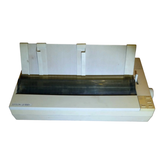
EPSON TERMINAL PRINTER L X — 1 0 5 0 + SERVICE MANUAL EPSON 4 0 0 3 2 8 3 ,’…
-
Page 2
All efforts have been made to ensure theaccuracyof the contents of this manuaI. However, should any errors be detected, SEIKO EPSON would greatly appreciate being informed of them. The above notwithstanding SEIKO EPSON can assume no responsibility for any errors in this manual or the consequence thereof. -
Page 3
THE POWER SUPPLY CABLE MUST BE CONNECTED, USE EXTREME CAUTION IN WORKING ON POWER SUPPLY AND OTHER ELECTRONIC COMPONENTS. REPAIRS ON EPSON PRODUCT SHOULD BE PERFORMED ONLY BY AN EPSON CERTIFIED REPAIR TECHNICIAN. MAKE CERTAIN THAT THE SOURCE VOLTAGE IS THE SAME AS THE RATED VOLT- AGE, LISTED ON THE SERIAL NUMBER/RATING PLATE. -
Page 4
The chapters are organized as follows: CHAPTER 1. GENERAL DESCRIPTION Provides a general product overview, lists specifications, and illustrates the main components of the printer. CHAPTER 2. OPERATING PRINCIPLES Describes the theory of printer operation. -
Page 5
REVISION SHEET Revision Issue Date Revision Page May 18, 1994 Rev. A issue… -
Page 6
TABLE OF CONTENTS CHAPTER 1. CHAPTER 2. CHAPTER 3. CHAPTER 4. CHAPTER 5. CHAPTER 6. APPENDIX GENERAL DESCRIPTION OPERATING PRINCIPLES DISASSEMBLY AND ASSEMBLY ADJUSTMENTS TROUBLESHOOTING MAINTENANCE vi -… -
Page 7: Table Of Contents
1.5.2 TAa Filter Unit……….1-16 1.5.3 Printer Mechanism (M-3D60)……. . . 1-16 Figure 1-1.
-
Page 8: List Of Tables
Table 1-1. Options for LX-105O+ ……..1-1 Table 1-2.
-
Page 9: Features
LX-105O+ Service Manual 1.1 FEATURES The LX-105O+ is a small, light-weight, low-cost, advanced paper handling printer. Its main features are: versions. Different parts are Program ROM version only. four The LX-105O+ has ROM version SOxxxx Standard version: ROM version Slxxxx…
-
Page 10
General Description Table 1-1 lists the optional units available Table 1-1. Options for LX-105O+ Cat. No. 8143 C82302*/C82304* C82303* 8165 C80624* i C80014* 8755 for the LX-1050+. Description New Serial Interface Board 32KB Serial Interface 32KB Parallel Interface IEEE-488 Interface Board Single Bin Cut Sheet Feeder [ PullTractorUnit Ribbon Cartridge… -
Page 11: Specifications
LX-105O+ Service Manual 1.2 SPECIFICATIONS This section provides detailed statistics for this printer. 1.2.1 Printing Specification Printing Method: Serial, impact, dot matrix Pin Configuration: 9 wires (diameter 0.29rnm) Figure 1-2. Bi-directional printing with logical seeking (Text mode) Print direction: Uni-directional (left to right) printing (Bit image mode) Print speed: See Table 1-2.
-
Page 12
General Description 9 X 9 matrix format: 18X 20 Text mode (NLQ 13 international character sets Ytaracter sets: ~haracter tables: See Table 1-3. Table 1-3. Character Tables Character Table ITALIC PC437 (US/ Standard Europe) PC850 (Multilingual) PC860 (Portuguese) PC863 (Canadian-French) PC865 (Nordic) PC866 (Russian) PC855 (Cyrillic) -
Page 13: General Description
LX-105O+ Service Manual Paper Handling Specification 1.2.2 1/6 inch or 1/8 inch, or programmable in units of 1/216 inch Line spacing: Approximately 95 ms (1/6 inch line feed) Line feed speed: Approximately 75 ms (1/6 inch in page feed) Friction feed Paper feed method: Tractor feed (push tractor: standard, pull tractor: optional) Rear…
-
Page 14
General Description Continuous paper 13 mm min. .———————————— Figure 1-4. Printable Area — Continuous Paper The adjust lever must be set to the proper position for the paper Adjust lever settings thickness. Table 1-4. Adjust Lever Settings Lever position 2nd step 3rd step Figure 1-5. -
Page 15: Reliability
LX-105O+ Service Manual 1.2.4 Ink Ribbon #8755 Ribbon Cartridge Type: Black Color: 3 million characters at 14 dots/character Reliability: 1.2.5 Environmental Conditions Temperature: -30 to60“C — Storage 5to35“C — Operation 5 to 85 Humidity: 10to801%0 2 G, 1 ms — Storage Resistance to shock: 1 G, 1 ms — Operation 0.50 G (55 Hz max.) — Storage…
-
Page 16: Interface Overview
ACKNLG is an acknowledge pulse with a width of approximately 10P.s. This signal goes LOW upon the completion of data reception, to indicates that the printer is ready to receive further data. The BUSY signal informs the host computer of the printer’s status.
-
Page 17: Optional Interface #8143
— runs out of paper. — off line. Signal ground. Used Pulled up to +5 V through 3.3 KQ resistor in the printer. The DC1/DC3 code is only valid when this signal is HIGH. 1 bit 1 bit or more…
-
Page 18: Printer Operations
1.4 PRINTER OPERATIONS This section describes the basic operations of the printer. 1.4.1 Control Panel The control panel of this printer contains four non-lock type push buttons and four LED indicators for easy ope;ation of the various printer function. [Buttons]…
-
Page 19: Selectype Functions
To select the Draft font, press the DRAFT button. The buzzer will sound once, indicating that the DRAFT font is selected. To set for condensed printing when the printer is in the print mode, press the CONDENSED button once (the buzzer will sound once), and the printer will enter the condensed print mode.
-
Page 20: Dip Switch Settings
General Description 1.4.5 DIP Switch Settings The two DIP switches are located on the side of the printer and function as shown in Tables 1-7 throum 1-10. Note status of the DIP switches is read only at power on or upon receipt of that the INIT signal.
-
Page 21
Manual LX-105O+ Service Table 1-9. Character Table Selection (DIP SW 1-5: ON) Sw 1-8 ~:pj:;d Sw 1-7 PC437 PC850 PC860 PC863 PC865 PC437 PC437 PC437 Table Rev. A India :?:/:: version PC437 PC437 PC437 PC866 PC437 PC869 PC437 Bulgaria PC437 PC437 PC437 PC437… -
Page 22: Buzzer Operation
This printer has EEPROM, it memorized SelecType settings, position of continuous paper, and bi-directional printing adjustment value. EEPROM reset operations are only required after the main board replacement, EEPROM replacement, or printer mechanism replacement. The EEPROM is cleared, when the printer power on while FF and LOAD/EJECT switches are pressed. 1-14 LX-105O+ Service Manual Rev.
-
Page 23: Main Components
D M-3D60: Printer mechanism. 1.5.1 TAMA Main Control Board The TAMA board is the main controller of this printer. It takes charge of interfacing with the host computer and processing of received print data, as well as control of the whole printer mechanism.
-
Page 24: Taa Filter Unit
TAa filter unit contains a power cord (120V Version) or AC inlet (220/240V Version), power switch, fuse filter circuit, and power transformer. 120V Version Figure 1-9. TAa Filter Unit 1.5.3 Printer Mechanism (M-3D60) The M-3D60 printer mechanism was developed specifically for the LX-105O+ printer. Its components include: Carriage motor Carriage mechanism Paper feed motor…
-
Page 25: Table Of Contents
Figure 2-1 Block Diagram of the Printer Mechanism ….2-1 Printhead-Printing Operation ……2-2 Figure 2-2 Figure 2-3.
-
Page 26
of Tables List Table 2-1. Ribbon-Feed Gear Train……..2-7 Table 2-2. -
Page 27: Overview
LX-105O+ Service Manual 2.1 OVERVIEW This section describes the operating principles of the printer mechanism and the electrical circuits of the LX-105O+. OPERATING PRINCIPLES OF THE PRINTER MECHANISM printer mechanism is composed of the printhead unit, paper feed mechanism, The LX-105O+ carriage drive mechanism, and various sensors.
-
Page 28: Printhead Printing Operation
Operating Principles 2.2.1 Printhead Printing Operation The dot-wire operation during printing is as follows. When the head-driving coil for a dot wire is energized, the actuating plate, which is engaged to one end of the dot wire, is attracted to the iron core, and drives the dot wire toward the platen.
-
Page 29: Carriage Drive Mechanism
LX-1050+ Service Manual Drive Mechanism 2.2.2 Carriage The carriage mechanism includes the printhead, the carriage, the timing belt, the carriage motor, and the platen. The timing belt is connected to the bottom of the carriage. The belt is driven by the carriage motor and moved via the beltdriven pulley.
-
Page 30: Paper Feed Mechanism Operation
Operating Principles 2.2.3 Paper Feed Mechanism Operation Friction feeding is used for cut sheets, and push tractor feeding is used for fanfold paper. Friction-Feed Operation The paper is held against the platen by paper-feed rollers. The paper-feed motor rotates the platen gear, via the paper-feed reduction gear, in the direction shown in following figure.
-
Page 31
LX-105O+ Service Manual Push Tractor Feed Operation When the push tractor unit is used, the paper is set such that its holes mesh with the tractor pins along the tractor belt. The paper feed motor is driven and, via the pinion on the motor shaft, rotates the gears in the direction shown in following figure, rotating the tractor belts. -
Page 32: Paperendsensor
Operating Principles Sensor 2.2.3.1 Paper End Following figure show the paper end sensor. This sensor switch is ON when no paper is in place (e.g., when the paper supply has run out.). Figure 2-7. Paper End Sensor Mechanism Release Sensor 2.2.3.2 The release sensor senses the position of the release lever in order to detect whether tractor feed or friction feed is in effect.
-
Page 33: Ribbon Advance Mechanism
LX-105O+ Service Manual 2.2.4 Ribbon Advance Mechanism The ribbon-feed mechanism consists of the ribbon cartridge and the ribbon-feed section. The ribbondriving gear is always driven counterclockwise (regardless of the timing belt direction) via the gear trains shown in following table. Table 2-1.
-
Page 34: Operating Principles Of The Electrical Circuitries
Operating Principles 2.3 OPERATING PRINCIPLES OF THE ELECTRICAL CIRCUITRIES This section describes principles of electrical circuitries. 2.3.1 Operating Principles of the Power Supply Circuit The electrical power required by this mechanism is developed combines a filter and a power transformer) and the T14NfA board. The Ac input passes first through the filter circuit, where line noise is removed, and is then set to the transformer, where it is stepped down into two separate voltages: AC 26V and AC 12C.
-
Page 35: Operating Principles Of The Main Control Circuit
LX-105O+ 2.3.2 Operating Principles of the Main Control Circuit The printer CPU is an 8-bit CPU ~D7810HG running at 15 MHz. It oversees control of all the components of the printer. The E05A30 gate array contains various memory management functions that control the assignment of the memory and 1/0 areas.
-
Page 36: Reset Circuits
E05A30 gate array. 2.3.2.1 Reset Circuit 11-tis circuit generates the signal that initializes the printer, and is made by monitoring the +5 and +24V voltages when the power is switched ON and OFF. The reset signal line is comect to the CPU and gate array 3B.
-
Page 37: Sensor Circuit
LX-105O+ Service Manual Sensor Circuit 2.3.2.2 Following figure shows the sensor circuit in block diagram. The PAO of CPU port senses carriage home position. The PA1 senses paper end. The PA2 senses release lever position. The AN5 of CPU A/D convertor senses +24V line voltage. HOME RELEASE +24V…
-
Page 38: Paper Feed Motor Drive Circuit
Operating Principles 2.3.2.4 Paper Feed Motor Drive Circuit paper-feed motor drive circuit is shown in following figure. me paper-feed motor is a step motor which can utilize 2-2 phase excitation. When the paper-feed signal PC2 is set to HIGH, Q20 and Q16 are turned on, and +24 V is supplied to the motor.
-
Page 39: Printhead Drive Circuit
LX-105O+ Service Manual Printhead Drive Circuit 2.3.2.5 Gate array E05A30 is used as an 8-bit + l-bit data latch. The CPU determines the pulse width for the head-wire drive pulses from gate array E05A30 by monitoring the printhead drive power (+24 V line).
-
Page 40: Host Interface
Operating Principles 2.3.2.6 Host Interface The host shown in following figure. STROBE pulses from the host computer pass interface circuit is through the low-pass filter, consisting of R72 and C12, and flow into the STROBE terminal. These pulses latch the parallel data and set the BUSY signal HIGH, so that subsequent data transfer is inhibited.
-
Page 41: Eeprom Circuit
LX-105O+ Service Manual Circuit 2.3.2.7 EEPROM The EEPROM stores in its memory the current feed position of continuously fed paper, as well as the current panel settings. This memory is retained even after power is shut off. EEPROM can memorize the current position of continuously fed paper, so that this information can be maintained even if power goes off.
-
Page 42
3.2.3.2 TA-a Filter Unit Removal……. 3-8 3.2.4 Removal of Printer Mechanism . .“……3-8 3.2.5 Disassembly of Printer Mechanism . -
Page 43
Figure 3-25. Paper Guide Plate Removal……3-16 Figure3-26. Adjust l_everRernoval ……. . . 3-17’ Figure 3-27. -
Page 44: General Repair Information
Prior to beginning any of these procedures, be certain that the AC power cord is disconnected. To help prevent hands jiotn being cut by the printer mechanism or sharp plate edges, wear gloves when performing these procedures. The printer mechanism, boards, and other parts are sometimes held in place with plastic clips rather than screws.
-
Page 45: Disassembly And Assembly
The disassembly procedure detailed below is in the following sequence: (1) removal of the printhead, (2) removal of the casings, (3) removal of the circuit boards, (4) removal of the printer mechanism unit, and (5) disassembly of the printer mechanism.
-
Page 46
LX-105O+ Service Manual Disassembly and Assembly [Step Unlock the two levers securing the printhead to thecarnage bypulhngthemdown. Then lift and remove the printhead. Levers Figure 3-2. Printhead Removal [Step Disconnect the head cable from theconnector ontheprinthead. Rev. A… -
Page 47: Removal Of Casing
3.2.2.1 Upper Casing Removal Remove the sheet guide unit, printer cover, paper tension unit, and paper feed knob. [Step 1] Pull in the two notches securing the push tractor to the printer mechanism, and remove [Step the push tractor from the printer mechanism.
-
Page 48
LX-105O+ Service Manual [Step While lifting the upper casing, discomect the cable of the control panel from connector CN3 on the TAMA board. Then remove the upper casing. Figure 3-5. Upper Casing Removai -2 NOTE FOR REASSEMBLY: Before reassembling the upper casin& prepare the FFC (Flat Flexible Cable) that connects the Control Panel and TAMA board in such a way that it can be connected to the Panel Cable Sailed Plate. -
Page 49: Control Panel Removal
LX-105O+ Service Manual Disassembly and Assembly Control Panel Removal 3.2.2.2 [Step 1] Remove the upper casing (as described in the previous section). [step Turn the upper casing over, push in the two notches on the casing that are securing the control panel to it, and remove the control panel.
-
Page 50: Removal Of Circuit Boards
LX-105O+ Service Manual 3.2.3 Removal of Circuit Boards This section describes the procedure for removing the TAMA Board Removal 3.2.3.1 Remove the upper casing (See section 3.2.2.1). The following connectors on the TAMA [Step 1] board, which are connecting it to external components, should be disconnected: CN4, CN5, CN6, CN7, CN8 FFC (Flexible Flat Cable), and CN9.
-
Page 51: Ta-A Filter Unit Removal
Disconnect the cables from the following connectors on the TAMA board: CN4 (red), [Step 1] CN5 (white), CN6 (black), and CN8 FFC (Flexible Flat Cable). [Step 2] Remove the fore C. B.B-tite (M4 x 12) screws securing the printer mechanism to the lower case. Remove the printer mechanism. [Step 3] II+M! Figure 3-10.
-
Page 52: Disassembly Of Printer Mechanism
LX-105O+ Service Manual 3.2.5 Disassembly of Printer Mechanism This section details the removal of components from the printer mechanism. 3.2.5.1 Removal of Carriage Motor [Step 1] Remove theprintermechanism (See section 3.2.4). [Step 2] Disconnect the motor cable from the carriage motor.
-
Page 53
Disassembly and Assembly 3.2.5.2 Removal of Home-Position [Step 1] Remove the printer mechanism. (See section3.2. [Step 2] Turn the printer mechanism upside-down. [Step 3] Push in the notch securing the home-position base frame. Figure 3-13. Home-Position Sensor Removal 3-10 LX-105O+ Service Manual… -
Page 54: Removalofplaten
LX-105O+ Service Manual 3.2.5.3 Removal of Platen [Step 1] Remove the printer mechanism. (See section 3.2.4) [Step2] Remove the paper tension unit. [Step3] Remove the C-ring (6) from the plate shaft. Figure 3-14. Cresent Ring Removal [Step C.B.N.Stite (M3 x 6) screws securing the platen cover and remove the Remove the two platen cover.
-
Page 55
Disassembly and Assembly 3.2.5.4 Separate of Frame [Step 1] Remove the platen. (See section 3.2.5.3) [Step 2] Remove the printhead. (See section 3.2.1) [Step3] Remove the FFC, head cable holder (L), and head cable holder (R) from base frame. Head Cable’ Hoder L Figure 3-16. -
Page 56
LX-105O+ Service Manual [Step 6] Push thetwonotches of the release lever outward. Remove the release lever. Figure 3-18. Release Lever Removal When the release lever is replaced, the markings should be analogously positioned. Marking Figure 3-19. Release Lever Replacement Rev. A Release Lever .’… -
Page 57
Separate the tractor cancellation cum from paper feed lever cancellation shaft. [Step Separation of Tractor Diseugage Cam Turn the printer mechanism upside-down, and manually move the carriage unit until it is [Step at the cut-out section of the base frame. The joint of the carriage unit and timing belt should be visible through the cut-out. -
Page 58: Removal Ofpaperfeed Motor
Separate side frames from base frame. CBS(0) (M3~ 6) Screws Figure 3-22. Separate When the printer mechanism is separated, perform the following adjustment. Section 4.1.3 Platen Gap Adjustment 3.2.5.5 Removal of Paper Feed Motor [Step 1] Separate side frames from base frame.
-
Page 59: Removal Ofpaperendsensor
[Step Separate side frames from base frame. (See section 3.2.5.4) Loosen the two bends securing the paper end sensor to the paper guide at the back of the [Step printer. Remove the paper end sensor. [Step 3] Figure 3-24. Paper Removal of Paper Guide Plate 3.2.5.7…
-
Page 60: Removal Ofcarriage
LX-105O+ Service Manual 3.2.5.8 Removal of Carriage [Step 1] %paratesideframes from base frame. (Seesection3.2.5 .4) [Step 2] Remove the HNO (M4) nut Securing theadjustlever, and remove the adjust lever. [Step 3] Remove the head adjust lever from thecarriage guide shaft. [Step 4] Remove thecarnageguide shaft and the carriage from the frame.
-
Page 61
LX-105O+ Service Manual Disassembly and Assembly Remove the tractor set L, the paper support, and tractor set R from the tractor and [Step 2] sprocket guide shafts. Figure 3-28. Extraction of Tractor Set NOTES FOR REASSEMBLY: When reassembling, align the phases as shown below. ‘,.-’, Figure 3-29. -
Page 62
Chapter 4 Adjustments Table of Contents 4.1 ADJUSTMENTS 4.1.1 Carriage Motor Backlash Adjustment ……4-1 4.1.2 Paper Feed Motor Backlash Adjustment. -
Page 63
LX-105O+ Service Manual ADJUSTMENTS section describes the adjustment procedures necessary when the LX-105O+ printer is This reassembled or when parts are reinstalled or replaced. These procedures are necessary to ensure the correct operation of the printer. 4.1.1 Carriage Motor Backlash Adjustment… -
Page 64
Adjustments 4.1.2 Paper Feed Motor Backlash Adjustment adjustment is required either when the paper This position is shifted. Separate side frames from base frame. (See section 3.2.5.4) CBS(0)(M3 x 6) screws on the paper feed motor. Loose the two 3. Manually rotate the paper feed motor, and adjust the backlash between the pinion and the appear feed reduction gear. -
Page 65
Following the removal of the carriage guide shaft or adjust lever, or if printing is abnormal, the gap between the platen and the print head should be adjusted. 1. Remove the printer mechanism (See section 3.2.4), Remove the printhead. Using tweezers, remove the ribbon mask. Remove the maskby pulling it slightly forward, then lifting. -
Page 66
Adjustments insert the blade of a screwdriver into the countersink of carnage guide shaft. < Countersink> Large / ’ ” Carriage G;ide Shaft B Figure 4-5. Platen Gap Adjustment 9. Adjust the platen gap using a thickness gauge, while rotating carnage guide shaft in the direction of the arrow in figure. -
Page 67
The printer stores the compensation data in the EEPROM on the main board (TAMA), and referring to this data when the bi-directional printing is performed. -
Page 68
Table 5-4. Symptoms and Problems……. . . 5-3 Table 5-5. The Printer does Not Operate at All ……5-4 Table 5-6. -
Page 69
LX-105O+ Service Manual 5.1 OVERVIEW Troubleshooting most other serial impact dot matrix printers is difficult to perform, since there may be wide variety of problems. Therefore, the LX-105O+ function that reduces troubleshooting time by identifying failed parts or selfdiagnostic components. The following tables and figure provide troubleshooting information. -
Page 70
This section describes operating conditions of each component. If any abnormality is detected, the printer displays an error message by beep sound. Table 5-3 lists the messages that tell you if service maintenance is required. -
Page 71: Troubleshooting
Each paragraph refers you to a detailed troubleshooting table. Table 5-4. Symptoms and Problems Symptom The printer does not operate at all. The LEDs on control panel does not oDerate at all. The buttons on control panel does not…
-
Page 72
Troubleshooting The Printer does Not Operate at Table 5-5. Cause Step The TA-a filter unit maybe dead. The TAMA board maybe bead. Table 5-6. The LEDs do Not Operate at All Step Cause Connector CN3 on the TAMA board may be disconnected. -
Page 73
The TAMA boards may be dead. Rev. A Checkpoint Turn the printer off and try to move the carriage manually. Does the carriage move smoothly? Does the carriage move and clash to right or left frame before error displayed? -
Page 74
Troubleshooting Table 5-9. Paper is Not Fed (1) Step Cause The paper Does the sensor toggle? sensor ‘ (Check with multimeter) may be dead. Does the sensor toggle? The release sensor (Check may be dead. Disconnect CN5 on the TAMA board and cheek the coil resistance between: pin 12 and pin 10;… -
Page 75
LX-105O+ Service Manual Table 5-10. Paper is Not Fed (2) Cause The paper end sensor may be dead. The release sensor may be dead. The paper feed motor may be dead. The paper path may be bad. Table 5-11. Paper Out Displayed Step Cause The paper end sensor… -
Page 76
Table 5-12. Abnormal Voltage Displayed Cause Step Connector CN5 and CN8 The CR motor, PF disconnect, and power on. motor or printhead coil Does printer not display abnormal is short. voltage? The TAMA board may — be bad. Table 5-13. Incorrect SRAM Displayed… -
Page 77
LX-105O+ Service Manual Table 5-16. Self-test Printout has Poor Quality (1) Cause Step The printhead wire may be broken. The printhead coil short or open. Rev. A Checkpoint Check the printhead. Are wires OK? Check the printhead coil resistance by multirneter. .(refer to figure 5-1) Are coils short or open? If any coil is shorted, check the… -
Page 78
Troubleshooting Table 5-17. Self-test Printout has Poor Quality (2) Step Cause Check the paper feed mechanism Paper feed mechanism gears and rollers. may be bad. Are there OK? Disconnect board and between: pin 12 and pin 10; pin 8 and pin 10; pin 11 and pin 9; pin 7 and pin 9 (4 points total) on the disconnected cable side using a multimeter. -
Page 79
Table 5-19. Abnormal Printing in On-line Step Cause Software setting may be bad. Dip switch settings of printer may be bad. Interface cable may be bad. The TAMA board may be bad. Table 5-20. Abnormal Printing in On-1ine Mode (3) -
Page 80
Table 5-21. Repair of the TAMA Board Condition Symptom IC 3A is defective The printer The +24V is ~oes not jead. >perate at all. IC 3Aor transistor Q1 (Q2) is defective. -
Page 81
LX-105O+ Service Manual Table 5-21. Repair of the TAMA Board (Continued) Condition Symptom rhe reset circuit s not operating. Selection of rhe printer CPU is mntrol ROM is joes not not operating. ~bnormal. >perate at all. 7AM is defective rhe CPU is… -
Page 82
LX-105O+ Service Manual Troubleshooting Table 5-21. Repair of the TAMA Board (Continued) Solution e..— +A — Check~oint Cause Pfinr4itinn Rev. A !5-14… -
Page 83
LX-105O+ Service Manual Troubleshooting Table 5-21. Repair of the TAMA Board (Continued) Rev. A 5-15… -
Page 84
Maintenance Chapter 6 Table of Contents 6.1 MAINTENANCE 6.1.1 Preventive Maintenance ..6.1.2 Lubrication and Adhesive Application Figure 6-1. Correct Adhesive Application ……6-2 Figure 6-2. -
Page 85
6.1.2 Lubrication and Adhesive Application EPSON recommends lubrication at the points illustrated in Figure 6-2. Table 6-2 provides a list of these points, and the recommended lubricant to be used for each. The lubricants—EPSON O-2, EPSON G-26, and EPSON G-37—have all been thoroughly tested and fully meet the needs of this printer. -
Page 86
Maintenance Table 6-2. Lubrication Points Ref. No. Contact portion of paper feed lever Contact portion of paper feed lever drive shaft and base frame Oil pad Contact portion of release lever and paper feed lever drive shaft Contact portion of adjust lever and side frame left Contact portion of adjust lever and side frame left Contact portion of belt pulley and ribbon gear Contact portion of carriage and carriage guide plate… -
Page 87
Maintenance LX-105O+ Service Manual Figure 6-2. Lubrication Points Rev. A… -
Page 88
LX-1050+ Exploded Diagram ……A-9 Figure A-6. Printer Mechanism Exploded Diagram ….. A-10 Figure A-7. -
Page 89
Figure below shows the intercomection between the major components of the LX-105O+. T A P N L — W Contrgrr~anel Release — . ——- L ———- HOST COMPUTER 1 Interconnection of Major Components Figure A-1. Rev. A Model 3D60 Printer Mechanism ;; Inn::; HOME HEAD Appendix 4>… -
Page 90
Appendix Table A-1. Connector Summary Connector Main TAMA Control Board I CN1 I Parallel interface Optional interface board connector Control panel Release lever CR motor and PF PE sensor ! CN7 I Home Position sensor Printhead AC voltage input CN1O Not used TA-a Filter Unit AC voltage… -
Page 91
LX-105O+ Service Manual Table A-2. Connector Pin Assignment — CN2 Pin No. Signal Name BUSY IN ITRD4 AC12 RESET AC12 +24V +12V — SLCTIN Table A-3. Connector Pin Assignment — CN3 Pin No. Sigrial N a m e UO LF SW FF SW LINE SW LIE SW… -
Page 92
Appendix Table A-5. Connector Pin Assignment — CN5 Pin No. Signal Name CRCDCOM CRABCOM PFCOM PFCOM Table A-6. Connector Pin Assignment — CN6 Signal Name Pin No. Table A-7. Connector Pin Assignment — CN7 Pin No. Signal Name HOME Table A-8. Connector Pin Assignment — CN8 Name Pin No. -
Page 93
LX-105O+ Sewice Manual INPUT Figure A-3. TA-a Filter Unit Circuit Diagram 200Q .O.lgF LED I $ GREEN Figure A-4. Control Panel Circuit Diagram Rev. A , “’J) LED2 GREEN LED4 Appendix ONLINE SW FF SW LF SW LD/EJ SW BUZZER READY LP ONLINE LP PE LP… -
Page 94
Appendix A.3 CIRCUIT BOARD COMPONENT LAYOUT II II Figure A-5. TAMA Main Control Board Component Layout LX-105O+ Service Manual Rev. A… -
Page 95: Exploded Diagram
LX-105O+ Service Manual EXPLODED DIAGRAM Figure A-6. LX-105O+ Exploded Diagram Rev. A Appendix A —…
-
Page 96
LX-105O+ Service Manual Appendix Figure A-7. Printer Mechanism Exploded Diagram Rev. A A-10… -
Page 97
EPSON OVERSEAS MARKETING LOCATIONS EPSON AMERICA, INC. 20770 Madrona Avenue, P.O. B 2842 Torrance, CA 90509-2642 Phone: (800) 922-8911 Fax: (310) 782-5220 EPSON UK LTD. Campus 100, Maylands Avenue, Hemel Hempstead, Herts. HP27EZ, U.K. Phone: 442-61144 Fax: 442-227227 EPSON IBERICA, S.A. -
Page 98
EPSON Printed in Japan 94.04-.2-G…
Найди любой мануал:
Например: Sony VGN-FW460J/T
Вы можете бесплатно скачать Инструкция по эксплуатации для Epson LX-1050+.
Также вы сможете прочесть онлайн этот документ без скачивания.
Скачать Инструкция по эксплуатации для Epson LX-1050+
Тип файла
PDF
Размер
1.79 Mb
Кол-во страниц
98
Просмотров
1998
Читать онлайн Инструкция по эксплуатации для Epson LX-1050+ (Страница 1)

Другие Принтеры Epson LX-1050+
Топ Epson Принтеры
Вопросы
Ранее вы смотрели
Эта страница полезна для вас? Поделитесь ссылкой:
-
Руководства по ремонту
1

Epson LX-1050+ сервис-мануал
(98 страниц)
-
Тип:
PDF -
Размер:
1.79 MB
Просмотр
Epson LX-1050+ (Принтеры) сервис мануалы в PDF-формате помогут найти неполадки и ошибки, а также осуществить ремонт Epson LX-1050+ и восстановить работу устройства.

- 1
- 2
- 3
- 4
- 5
- 6
- 7
- 8
- 9
- 10
- 11
- 12
- 13
- 14
- 15
- 16
- 17
- 18
- 19
- 20
- 21
- 22
- 23
- 24
- 25
- 26
- 27
- 28
- 29
- 30
- 31
- 32
- 33
- 34
- 35
- 36
- 37
- 38
- 39
- 40
- 41
- 42
- 43
- 44
- 45
- 46
- 47
- 48
- 49
- 50
- 51
- 52
- 53
- 54
- 55
- 56
- 57
- 58
- 59
- 60
- 61
- 62
- 63
- 64
- 65
- 66
- 67
- 68
- 69
- 70
- 71
- 72
- 73
- 74
- 75
- 76
- 77
- 78
- 79
- 80
- 81
- 82
- 83
- 84
- 85
- 86
- 87
- 88
- 89
- 90
- 91
- 92
- 93
- 94
- 95
- 96
- 97
- 98
- 99


На чтение 2 мин. Просмотров 27 Опубликовано 15.12.2019
Страница скачивания руководства по обслуживанию Epson LX-1050+
Размер: 1,88 MB
Добавлено: 2014-02-19 12:23:48
Количество страниц: 98
Скачивание руководства по обслуживанию Epson LX-1050+ должно начаться в течении нескольких секунд. Если загрузка не началась автоматически в течение 10 секунд, нажмите на Прямая ссылка. Если у Вас остаются проблемы со скачиванием инструкции Epson LX-1050+, свяжитесь с нами, используя формуляр для сообщения об ошибках.;
Если у вас отсутствует техническая возможность для скачивания Инструкция по эксплуатации для Epson LX-1050+
вы можете прочесть документ прямо на нашем сайте или
Скачать Epson LX-1050+ Инструкция по эксплуатации
Марк : EPSON
Категория : Компьютеры
Подкатегория : Принтер
Продукт : LX-1050
Наш сайт предлагает вам бесплатный доступ к руководству по EPSON LX-1050 ,
руководство пользователя по EPSON LX-1050 .
Найти руководство пользователя по LX-1050 нажав на ссылку ниже.
Установка учебники, Руководство по эксплуатации, Руководство пользователя для EPSON LX-1050
Ниже вы найдете руководство пользователя по данному продукту. Руководства для владельца, руководства пользователя и руководства по эксплуатации являются оригинальными материалами торговых марок. Данное руководство пользователя доступно на различных языках.
Руководство по эксплуатации для EPSON LX-1050 — LX1050
Чтобы просмотреть руководство пользователя по LX-1050 .
Adobe Acrobat Reader должен быть установлен в системе. Для бесплатной загрузки Acrobat Reader нажмите на ссылку.

Нажмите на ссылку, и вы будете перенаправлены. Пожалуйста, дождитесь окончания загрузки файла.
Руководство пользователя, Руководство пользователя, Руководство по эксплуатации для похожие продукты
Этот сайт международный сайт, бесплатно, предлагая инструкции по эксплуатации EPSON, Руководства пользователя EPSON, Руководство по эксплуатации EPSON и технических руководств. EPSON для загрузки. Теги: Установкo учебники EPSON — Руководства пользователя EPSON — руководства по монтажу EPSON — Технические руководства EPSON — руководство по обслуживанию EPSON — руководство по установке EPSON — Установка учебники EPSON — Руководство пользователя EPSON
Все названия и торговые марки являются собственностью их владельцев.