ОГЛАВЛЕНИЕ
1.
ВВЕДЕНИЕ
. . . . . . . . . . . . . . . . . . . . . . . . . . . . . . . . . . . . . . . 4
2.
ОБЩИЕ
СВЕДЕНИЯ
О
СИСТЕМЕ
И
КОМПОНЕНТАХ
. . . . . . . . . . . . . . . . . . . . .. 5
2.1
Т
ИПЫ
ПКП
E
SSER BY
H
ONEYWELL
. . . . . . . . . . . . . . . . . . . . . . . . . . . . .. 5
2.2
Т
ИПЫ
ПРИМЕНЯЕМОГО
ПЕРИФЕРИЙНОГО
ОБОРУДОВАНИЯ
. . . . . . . . . . . . . . . . . . . … 5
3.
ВНУТРЕННЯЯ
СТРУКТУРА
КОНТРОЛЬНЫХ
ПАНЕЛЕЙ
. . . . . . . . . . . . . . . . . . . . 6
3.1
С
ЕРИЯ
IQ8C
ONTROL
. . . . . . . . . . . . . . . . . . . . . . . . . . . . . . . . . … 6
3.1.1
ПКП
IQ8Control C
. . . . . . . . . . . . . . . . . . . . . . . . . . . . . . . . .. 6
3.1.2
ПКП
IQ8Control M
. . . . . . . . . . . . . . . . . . . . . . . . . . . . . . . . . 8
3.1.3
Лицевые
панели
для
ПКП
IQ8Control
С
/M
. . . . . . . . . . . . . . . . . . . . . . 10
3.2.1
ПКП
FX2
. . . . . . . . . . . . . . . . . . . . . . . . . . . . . . . . . . . . 11
3.2.2
ПКП
FX10
. . . . . . . . . . . . . . . . . . . . . . . . . . . . . . . . . . . .. 13
3.2.3
ПКП
FX18
. . . . . . . . . . . . . . . . . . . . . . . . . . . . . . . . . . . .. 15
3.2.4
Лицевые
панели
для
ПКП
FlexES Control
. . . . . . . . . . . . . . . . . . . . . . 17
3.2.5
Платформы
расширения
для
ПКП
FlexES Control
. . . . . . . . . . . . . . . . . . 17
3.2.6
Модули
для
ПКП
FlexEs Control
. . . . . . . . . . . . . . . . . . . . . . . . . .. 18
3.2.7
Расширение
блоков
питания
ПКП
FlexEs Control
. . . . . . . . . . . . . . . . . .. 18
3.2.8
Конфигуратор
заказных
позиций
ПКП
FlexEs Control FX10 / FX18
в
стоечной
(19”)
версии
. . 20
3.2.8
Выносные
пульты
управления
для
ПКП
FlexEs Control
. . . . . . . . . . . . . . .. 21
3.3
Р
ЕКОМЕНДАЦИИ
ПО
ОСОБЫМ
СЛУЧАЯМ
ПРИМЕНЕНИЯ
ПКП
IQ8C
ONTROL
И
F
LEX
E
S
C
ONTROL
. . . . . .. 21
3.3.1
Русскоязычные
дескрипторы
в
сети
essernet
®
. . . . . . . . . . . . . . . . . . 21
4.
ОБЪЕДИНЕНИЕ
КОНТРОЛЬНЫХ
ПАНЕЛЕЙ
В
СЕТЬ
ESSERNET
®
. . . . . . . . . . . . . . . 23
4.1
О
БЩИЕ
СВЕДЕНИЯ
. . . . . . . . . . . . . . . . . . . . . . . . . . . . . . . . . . 23
4.3
О
СОБЕННОСТИ
И
ИНФОРМАЦИЯ
ПО
УСТАНОВКЕ
МИКРОМОДУЛЕЙ
ESSERNET
®
. . . . . . . . . . . . . 24
4.3.1
Для
модуля
essernet
®
62,5 kBd:
. . . . . . . . . . . . . . . . . . . . . . . . . .. 24
4.3.2
Для
модуля
essernet
®
500 kBd:
. . . . . . . . . . . . . . . . . . . . . . . . . … 24
4.4
П
ОДКЛЮЧЕНИЕ
ESSERNET
®
. . . . . . . . . . . . . . . . . . . . . . . . . . . . . . . 24
4.4.1
Подключение
медным
кабелем
. . . . . . . . . . . . . . . . . . . . . . . . . .. 24
4.5
П
ОСЛЕДОВАТЕЛЬНЫЙ
ИНТЕРФЕЙС
ESSERNET
®
(SEI) . . . . . . . . . . . . . . . . . . . . . . 26
4.5.1
Подключение
к
системе
Variodyn D1
. . . . . . . . . . . . . . . . . . . . . . . 26
4.5.2
Подключение
к
WinmagPlus
. . . . . . . . . . . . . . . . . . . . . . . . . . . 27
4.5.3
Мультипротокольные
шлюзы
MPG
. . . . . . . . . . . . . . . . . . . . . . . 27
4.5.4
Удалённое
подключение
пожарных
станций
. . . . . . . . . . . . . . . . . . . . 29
5.1
Р
АЗНОВИДНОСТИ
АНАЛОГОВО
—
КОЛЬЦЕВЫХ
ШЛЕЙФОВ
СПС
E
SSER
. . . . . . . . . . . . . . . .. 30
5.2
О
СОБЕННОСТИ
ПРИМЕНЕНИЯ
АНАЛОГОВО
—
КОЛЬЦЕВЫХ
ШЛЕЙФОВ
. . . . . . . . . . . . . . . . 30
5.2.1
Преимущества
аналогово
—
кольцевых
шлейфов
. . . . . . . . . . . . . . . . . .. 30
5.2.2
Радиальные
ответвления
. . . . . . . . . . . . . . . . . . . . . . . . . . . . 30
6
ПЕРИФЕРИЙНЫЕ
УСТРОЙСТВА
ШЛЕЙФА
. . . . . . . . . . . . . . . . . . . . . . . . 32
6.1
О
БЩИЕ
ОСОБЕННОСТИ
ПРИМЕНЯЕМОЙ
ПЕРИФЕРИИ
. . . . . . . . . . . . . . . . . . . . . .. 32
6.1.1
Информация
по
расчёту
кольцевого
шлейфа
типа
esserbus
®
-Plus
. . . . . . . . . 32
6.2
А
НАЛОГОВО
—
АДРЕСНЫЕ
АВТОМАТИЧЕСКИЕ
ПОЖАРНЫЕ
ИЗВЕЩАТЕЛИ
СЕРИИ
IQ8Q
UAD
. . . . . . . . 33
6.2.1
Основные
особенности
серии
. . . . . . . . . . . . . . . . . . . . . . . . . … 33
6.2.2
Классификация
извещателей
серии
IQ8Quad
. . . . . . . . . . . . . . . . . . . 33
6.3
Р
УЧНЫЕ
ПОЖАРНЫЕ
ИЗВЕЩАТЕЛИ
СЕРИИ
IQ8Q
UAD
. . . . . . . . . . . . . . . . . . . . . . 43
6.3.1
Извещатели
в
малом
корпусе
. . . . . . . . . . . . . . . . . . . . . . . . . … 43
6.3.2
Извещатели
в
большом
корпусе
. . . . . . . . . . . . . . . . . . . . . . . . .. 45
6.4
А
ДРЕСНЫЕ
РАСШИРИТЕЛИ
(
ТРАНСПОНДЕРЫ
И
МОДУЛИ
) . . . . . . . . . . . . . . . . . . . … 47
6.4.1
Транспондеры
с
входными
и
выходными
сигналами
. . . . . . . . . . . . . . . .. 47
6.4.3
Принадлежности
к
транспондерам
. . . . . . . . . . . . . . . . . . . . . . . . 51
6.4.4
Модули
управления
и
контроля
. . . . . . . . . . . . . . . . . . . . . . . . . 52
Особенности
логики
работы
модулей
FCT
. . . . . . . . . . . . . . . . . . . . . . 52
См
.
также
п
. 9.1.3
. . . . . . . . . . . . . . . . . . . . . . . . . . . . . . . . . … 52
6.4.5
Типовые
схемы
подключения
. . . . . . . . . . . . . . . . . . . . . . . . . . 54
6.5
А
ДРЕСНЫЕ
ТРЕВОЖНЫЕ
ОПОВЕЩАТЕЛИ
IQ8A
LARM
. . . . . . . . . . . . . . . . . . . . . .. 62
6.5.1.
Разновидности
адресных
тревожных
оповещателей
. . . . . . . . . . . . . . .. 62
7.1
О
БЩИЕ
СВЕДЕНИЯ
. . . . . . . . . . . . . . . . . . . . . . . . . . . . . . . . . . 63
7.2
Р
АЗНОВИДНОСТИ
БЕСПРОВОДНЫХ
КОМПОНЕНТОВ
. . . . . . . . . . . . . . . . . . . . . . 63
7.2.1
Центральноеприёмно
—
передающее
оборудование
. . . . . . . . . . . . . . . . .. 63
3
7.2.2
Периферийное
приёмно
—
передающее
оборудование
. . . . . . . . . . . . . . . … 64
7.2.3
Принадлежности
. . . . . . . . . . . . . . . . . . . . . . . . . . . . . . . .. 66
7.2.4
Системные
ограничения
. . . . . . . . . . . . . . . . . . . . . . . . . . . . 66
8
ИЗВЕЩАТЕЛИ
ДЛЯ
ОСОБЫХ
УСЛОВИЙ
ПРИМЕНЕНИЯ
. . . . . . . . . . . . . . . . . . . 67
8.1
В
ЗРЫВОБЕЗОПАСНЫЕ
ИЗВЕЩАТЕЛИ
СЕРИИ
IQ8Q
UAD
E
X
. . . . . . . . . . . . . . . . . . . . 67
8.2
И
ЗВЕЩАТЕЛИ
ДЛЯ
ВЕНТКАНАЛОВ
. . . . . . . . . . . . . . . . . . . . . . . . . . . . .. 71
8.3
Л
ИНЕЙНЫЕ
ДЫМОВЫЕ
ИЗВЕЩАТЕЛИ
. . . . . . . . . . . . . . . . . . . . . . . . . . . . 72
8.3.1
Модификации
. . . . . . . . . . . . . . . . . . . . . . . . . . . . . . . . . . 72
8.3.2
Схемы
подключения
. . . . . . . . . . . . . . . . . . . . . . . . . . . . . . . 73
8.4
Л
ИНЕЙНЫЕ
ТЕПЛОВЫЕ
ИЗВЕЩАТЕЛИ
. . . . . . . . . . . . . . . . . . . . . . . . . . . . 74
8.4.1
Конвенциональные
извещатели
. . . . . . . . . . . . . . . . . . . . . . . . … 74
8.5
А
СПИРАЦИОННЫЕ
ИЗВЕЩАТЕЛИ
. . . . . . . . . . . . . . . . . . . . . . . . . . . . . 78
8.5
И
ЗВЕЩАТЕЛИ
ПЛАМЕНИ
. . . . . . . . . . . . . . . . . . . . . . . . . . . . . . . . . 79
9
УПРАВЛЕНИЕ
ПОЖАРНОЙ
АВТОМАТИКОЙ
. . . . . . . . . . . . . . . . . . . . . . . … 82
9.1
В
ОЗМОЖНОСТИ
ПРАКТИЧЕСКОЙ
РЕАЛИЗАЦИИ
. . . . . . . . . . . . . . . . . . . . . . . … 82
9.1.1
Выделенные
шлейфы
под
автоматику
. . . . . . . . . . . . . . . . . . . . . .. 82
9.1.2
Выделенные
под
автоматику
контрольные
панели
. . . . . . . . . . . . . . . .. 83
9.1.3
Преимущества
транспондеров
FCT
. . . . . . . . . . . . . . . . . . . . . . . 83
10
ПРОГРАММНОЕ
ОБЕСПЕЧЕНИЕ
. . . . . . . . . . . . . . . . . . . . . . . . . . . . 84
10.1
П
РОГРАММНОЕ
ОБЕСПЕЧЕНИЕ
ДЛЯ
ПУСКО
—
НАЛАДКИ
. . . . . . . . . . . . . . . . . . . . … 84
10.2
П
РОГРАММНОЕ
ОБЕСПЕЧЕНИЕ
ДЛЯ
МОНИТОРИНГА
. . . . . . . . . . . . . . . . . . . . . .. 84
ПРИЛОЖЕНИЕ
A —
ОПРЕДЕЛЕНИЕ
АДРЕСНОГО
ПРОСТРАНСТВА
НА
ШЛЕЙФЕ
ESSERBUS . . . .. 85
A.1
Ф
ИЗИЧЕСКИЕ
АДРЕСА
. . . . . . . . . . . . . . . . . . . . . . . . . . . . . . . . . 85
A.2
Л
ОГИЧЕСКИЕ
АДРЕСА
. . . . . . . . . . . . . . . . . . . . . . . . . . . . . . . . . . 85
A.2.1
Логическая
группа
,
как
объединение
адресных
устройств
. . . . . . . . . . . . .. 85
A.2.1
Логическая
группа
,
как
единичный
входной
сигнал
. . . . . . . . . . . . . . . . 85
A.2.3
Подсчёт
общего
количества
логических
групп
,
используемых
на
шлейфе
. . . . . 85
A.3
Л
ИМИТИРОВАНИЕ
УСТРОЙСТВ
НА
ШЛЕЙФЕ
В
ЗАВИСИМОСТИ
ОТ
ТИПА
. . . . . . . . . . . . . . . .. 86
A.4
Л
ИМИТИРОВАНИЕ
УСТРОЙСТВ
НА
УРОВНЕ
КОНТРОЛЬНОЙ
ПАНЕЛИ
. . . . . . . . . . . . . . . . .. 87
A.5
А
ДРЕСАЦИЯ
ВЫХОДНЫХ
СИГНАЛОВ
. . . . . . . . . . . . . . . . . . . . . . . . . . . . 87
———————————————————
>>> СКАЧАТЬ ФАЙЛ <<<
———————————————————
Проверено, вирусов нет!
———————————————————

.
.
.
.
.
.
.
.
.
.
.
.
.
.
.
.
.
.
.
.
.
.
.
.
.
.
.
.
.
.
.
.
.
.
.
В 1973 году Klaus Esser, известный строительный бизнесмен Германии. Руководство по проектированию пожарной сигнализации ESSER ред.2009. Esser by Honeywell пожарка пожарная сигнализация IQ8 esserbus. Август 2017. 14.08, FA-204 Проектирование САПС Esser, 8, Записаться. 15.08 -. В перечень выпускаемого оборудования Esser by Honeywell входят. Общее руководство по проектированию систем пожарной сигнализации Esser by. Общее руководство по проектированию систем пожарной сигнализации на базе оборудования Esser by Honeywell. ОГЛАВЛЕНИЕ. 1. ВВЕДЕНИЕ; 2. Данное руководство описывает сборку корпуса и установку новой пожарной контрольной панели FlexES control. Для проектирования, эксплуатации и. Общее руководство по проектированию систем речевого оповещения на базе оборудования VARIODYN® D1. ОГЛАВЛЕНИЕ. 1. БАЗОВОЕ. Пожалуйста, всегда консультируйтесь с нашей службой технической подержки при проектировании систем и составлении спецификаций оборудования. и предоставляет полнофункциональную интеграцию с пожарными системами ESSER by. нера для проектирования, установки и технического обслу-. Сетевая автоматическая пожарная сигнализация Esser by Honeywell с возможностью подключения радиоканальных устройств и датчиков с. в Россию компанией «ВАЙФАЙНДЕР», ESSER by Honeywell, ESMI, Novar. Общее руководство по проектированию систем речевого оповещения на. В состав рабочей группы под руководством менеджера проекта входят. опыт работы с многими известными системами, в том числе APOLLO, ESSER и др. Проектный отдел компании имеет многолетний опыт проектирования. Осуществляет общее руководство деятельностью компании, определяет. Руководит составлением технических заданий на проектирование систем. Cerberus, ESSER by Honeywell, ИС Орион , Рубеж, РОСА, Apollo Apacs. ну, для этого надо при проектировании закладывать запас по размеру/ сечению в коробах/трубах. Esser все мозги вынес бы на утечку по плюсу или минусу. У Вас Игорь Николаевич руководство какого года? Подготовка задания на проектирование, технических заданий и участие в подготовке. Техническое руководство проектными работами. by Honeywell, проектирование систем пожарной сигнализации ESSER by Honeywell. Сейчас проектирование предприятий химической промышленности играет ведущую роль в современной индустрии. Учитывая особенности их работы. организацию и проведение НИР и НИОКР;; моделирование технологических процессов;; патентные и рыночные исследования;; проектирование и. Специалисты TEGRUS получили сертификаты от ESSER. полного цикла, расширил спектр компетенций в области проектирования. Книга представляет собой полное руководство по издательской системе LATEX. LATEX создан для логического проектирования печатного документа. Она ведёт свою родословную от системы teTeX Томаса Эссера (Esser. Под руководством профессоров из Бизнес Школы Северного. СПбПУ, генеральный директорGETInformationTechnologyGmbH д-р Эссер Манфред). о работах института в области проектирования энергетических объектов и. проектирование систем безопасности, постгарантийное обслуживание. ESSER Forteza G.S.N. Electronic Getcall Honeywell HostCall. Legrand Optex
-
Contents
-
Table of Contents
-
Bookmarks
Related Manuals for Esser 8000C
Summary of Contents for Esser 8000C
-
Page 1
Operation and Installation Instruction Fire Alarm Computer 8000C / M… -
Page 2
Danger of death, severe injury or considerable material damage if the relevant safety precautions are not observed. ☞ Important information on the product or a particular section of this manual, which should be read with particular attention. Page 2 Fire Alarm Computer 8000C / M… -
Page 3: Table Of Contents
4.9 Lamp test ………………………..39 Service Level ……………………….40 5.1.1 Primary loop functions………………..41 5.1.2 Sensor functions (loop) ………………..43 5.1.3 Sensor functions (zone/detector) ……………… 45 Installation Instruction……………………..47 Micromodule……………………….107 Commissioning / Servicing …………………… 145 Fire Alarm Computer 8000C / M Page 3…
-
Page 4: General
These Operating Instructions are intended to aid you in the operation of the Fire Alarm Computer 8000C / M in addition to the description provided by the specialised installer and should be kept together with the technical documentation of the fire alarm system. If you have any questions, please consult your specialised installer.
-
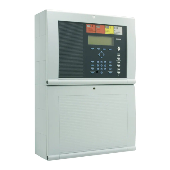
Page 5: General View
Fig. 1: General view of the display and operating elements Single zone indicator units (GEA) Common display FIRE Common display PRE-ALARM Common display TROUBLE Common display disconnection Alphanumeric display Key switch Operating elements Function keys and keyboard Fire Alarm Computer 8000C / M Page 5…
-
Page 6: Key Switch / Enabling Operation
Key switch in horizontal position locked unlocked Fig. 2: Keyboard unlocked ♦ The keyboard is unlocked for the operation of the single Fire Alarm Computer 8000C / M and ® other processors interconnected through the essernet ♦ The display menu is activated.
-
Page 7: Function Of The Display And Operating Elements
With the four function keys, the menu options positioned above them in the alphanumeric display are selected. Depending on the current state of the fire alarm control panel or the operation level, differing menu options are shown in the display. Fire Alarm Computer 8000C / M Page 7…
-
Page 8
(e.g. fire department) has been alarmed. Notify fire department Red LED is permanently on ⇒ The master box (MB) has malfunctioned or is switched off and cannot be activated. Call the fire department immediately ! Page 8 Fire Alarm Computer 8000C / M… -
Page 9
Control actions assigned to this event by means of customer data programming, e.g. relay outputs for activating internal signalling devices or evacuation signals will be executed. ☞ On pre-alarm, the master box for alarming the emergency services will not be activated. Fire Alarm Computer 8000C / M Page 9… -
Page 10
The programmed Verify time (max. 600 seconds) for the Verify of the cause of the alarm is running. The master box is only activated after the expiry of the Verify time. ☞ The function delay/Verify is described in Section 4.7. Page 10 Fire Alarm Computer 8000C / M… -
Page 11
Yellow LED is permanently on ⇒ The power supply (battery or mains voltage) is out of order. ☞ In cases of malfunction or emergency operation, correct functioning of the FACP is no longer ensured. Inform customer/maintenance service! Fire Alarm Computer 8000C / M Page 11… -
Page 12
⇒ A component of the control panel (e.g. detector zone) has been set to Testmode for servicing and maintenance work. A detector zone in Testmode will not transmit an alarm in the case of an event. Page 12 Fire Alarm Computer 8000C / M… -
Page 13
Optical displays (LED) for a total of 64 detector zones may be integrated into the control panel of the fire alarm computer 8000C / M. Fire is signalled by a red LED. Malfunctions and disconnections are signalled by a yellow LED. There is a labelling field for each detector zone which can be marked with the name of the zone or of the area monitored by this group of detectors. -
Page 14
Disconnect function). Switch-offs are displayed visually in the Common display Master Box disconnection field. Switched off alarm devices and master boxes will not transmit an alarm in the case of an event. Page 14 Fire Alarm Computer 8000C / M… -
Page 15
The Delay/Verify function is explained in section 4.7. Buzzer off Acknowledgement of the control panel buzzer. This key remains active when the keyboard is locked. The buzzer is reactivated in the case of a further event. Fire Alarm Computer 8000C / M Page 15… -
Page 16: Operating Status Of The Fire Alarm Control Panel
Operating status of the fire alarm control panel Operating status of the fire alarm control panel The current operating status of the fire alarm control panel 8000C / M is shown on the operating panel. Six different operating conditions are possible:…
-
Page 17: Trouble
The master box and the Master box (MB) LED and Notify fire department will be activated even in the control panel CPU failure mode. A comprehensive operation of the fire alarm control panel is no longer provided. Call customer/maintenance service immediately! Fire Alarm Computer 8000C / M Page 17…
-
Page 18: Disconnection
The yellow LED Testmode lights. The Testmode mode of the control panel has been activated for service and maintenance purposes: ♦ The function of detectors/detector zones is under inspection. A detector zone in Testmode will not signal an alarm in the case of an event. Page 18 Fire Alarm Computer 8000C / M…
-
Page 19: Operation
The following section describes the most important operating actions for a single fire alarm control ® panel 8000C / M. If several processors are connected in a network through the essernet deviations from this description are possible. In this case, please ask your specialised installer.
-
Page 20
If information or additional text has been programmed for a message, the additional text (Param/AT) is always displayed first. Pushing the function key during the display of the additional text shows the information text. Page 20 Fire Alarm Computer 8000C / M… -
Page 21: Display / Display Control
♦ The display field Info shows that an information text has been programmed for this detector zone, which can be accessed by pressing the corresponding function key. Fire Alarm Computer 8000C / M Page 21…
-
Page 22
Acoustic disconnected when at least one acoustic alarm device has been disconnected. Revision active when the fire alarm control panel has been switched to revision on the fire department operating panel. Page 22 Fire Alarm Computer 8000C / M… -
Page 23: Display Priority Of The Messages In The Display
The first and last message with the highest current priority are shown in the alphanumeric display of the Fire alarm control panel 8000C / M respectively. If several messages with equal priority are imminent, these can be queried by pressing the key Additional Messages.
-
Page 24: Info Text / Additional Text And Parameter Display
Info text / additional text and parameter display ☞ Pressing the Condition function key returns the panel to the condition display. The display switches automatically to the preceding menu point approx. 20 sec. after the last operation. Page 24 Fire Alarm Computer 8000C / M…
-
Page 25: Entering Time/Date
Entering times for the function Delay/Verify; see Section 4.6 ! ☞ Approx. 20 seconds after the last operating action, the display switches back automatically to the last menu point without storing the changes/inputs ! Fire Alarm Computer 8000C / M Page 25…
-
Page 26: Detector Zones
Fire or Trouble are deleted. Zone Press Key Fig. 16: Switching on / resetting a detector zone 4 (example) Operation Zone: Detector: in progress Fig. 17: Display switching on zone 4 Page 26 Fire Alarm Computer 8000C / M…
-
Page 27: Disconnect A Detector Zone
11:10 22:11 Additional text (client text) Overview Service Time funct. Info Fig. 20: Disconnect to status display A disconnected detector zone will not signal an alarm in the case of an event! Fire Alarm Computer 8000C / M Page 27…
-
Page 28: Status Of A Detector Zone
With this function, the current status, e.g. Normal, Alarm and Trouble, of the corresponding detector zone can be interrogated directly. Zone Status query Press Key Fig. 21: Status detector zone 2 (example) Operation Zone : 0002 Status: normal Fig. 22: Display Status zone 2 Page 28 Fire Alarm Computer 8000C / M…
-
Page 29: Detectors
Detectors Detectors Functions relating to detectors are only possible for addressable fire detectors of the ESSER detector series 9100 and 9200. These fire detectors can be selected and controlled by a detector address. 4.4.1 Switching on / resetting a detector…
-
Page 30: Disconnect A Detector
Common display Disconnect field. Individual detectors within a detector zone can only be disconnected if addressable ESSER series 9100 and 9200 detectors are used. Series 9000 standard fire detectors can not be disconnected individually.
-
Page 31: Status Of A Detector
With this function, the current status, e.g. Normal, Alarm and Trouble, of the corresponding detector can be queried directly. Individual status query within a detector zone is only possible if addressable ESSER series 9100 and 9200 detectors are used. Series 9000 standard fire detectors can not be queried individually.
-
Page 32: Controls
In case of an event, the switched-on output will be controlled in accordance with the programmed control conditions. Relay Press Key Fig. 29: Switching on Relay 2 (example) Operation Relay : 2 in progress Fig. 30: Display switching on Relay 2 Page 32 Fire Alarm Computer 8000C / M…
-
Page 33: Disconnect A Control Output
Fig. 32: Display disconnect Relay 2 Relays may be set to inverse by means of customer data programming of the 8000C / M FACP. In this case, the relays will be activated in the normal state of the FACP and deactivated in case of the associated event.
-
Page 34: Status Of A Control Output
Fig. 34: Display status Relay 2 Relays may be set to inverse by means of customer data programming of the 8000C / M FACP. In this case, the relays will be activated in the normal state of the FACP and deactivated in case of the associated event.
-
Page 35: Common Display Of The Status Messages
Fig. 36: Display for a detailed status message fire alarm (example) Additional text line associated with the triggered zone/detector (example) Additional information or parameters may be displayed by pressing function key Info. Fire Alarm Computer 8000C / M Page 35…
-
Page 36: Delay And Verify
If this function is not activated, e.g. for technical reasons or requirements, the functions described in this section can not be used. Page 36 Fire Alarm Computer 8000C / M…
-
Page 37: Delay
Verify of the cause of the alarm by pressing this key. Verify Buzzer off Fig. 39: Verify key The guidelines of the Association of German Property Insurance Companys (Verband der Schadenversicherer VdS, Cologne) must be observed for the function Delay and Verify. Fire Alarm Computer 8000C / M Page 37…
-
Page 38: Alarm Counter
® The sum of all alarm signals detected in the essernet network amounts to 50 fire alarms and 7 technical alarms (TAL alarms). ☞ The alarm counter cannot be reset to -0000-. Page 38 Fire Alarm Computer 8000C / M…
-
Page 39: Lamp Test
The versions No. of the panel software is then shown on the display. This function ends automatically after approx. 10 seconds! Pressing the Test key again stops the lamp test before the expiry of 10 seconds! Fire Alarm Computer 8000C / M Page 39…
-
Page 40: Service Level
FACP may only be carried out by authorised and trained persons under observance of the safety precautions and, if necessary, in cooperation with the emergency services (e.g. fire department). Page 40 Fire Alarm Computer 8000C / M…
-
Page 41: Primary Loop Functions
When a primary loop, for example a 4-zone module or an analog loop module is disconnected, all zones and loop devices connected to this module are disconnected. Disconnected fire detectors and call points will not activate an alarm in the case of an event. Fire Alarm Computer 8000C / M Page 41…
-
Page 42
Example FACP 8000M Definition of primary loop numbers Individual assemblies of the FACP 8000C/M can be switched on/off with the internal primary loop number through the control panel keyboard or programmed with the customer data editor. This internal primary loop number is composed of the control panel number, the slot and the assembly number. -
Page 43: Sensor Functions (Loop)
Switching off sensors is only possible for OH and OHI multisensor fire detectors. If multisensor fire detectors and standard detectors (detectors with a single sensor) are installed together in an analog loop, only the sensor in multisensor detectors are switched off. Fire Alarm Computer 8000C / M Page 43…
-
Page 44
In order to change the existing sensor switching status, all disconnected detector sensors must first be switched on, for example with the command All sensors on. After all detector sensors have been switched on, a further switching off/sensor disconnect can be performed. Page 44 Fire Alarm Computer 8000C / M… -
Page 45: Sensor Functions (Zone/Detector)
It is possible to switch off other detector zones of this analog loop in which detectors or sensors have not been switched off. Fire Alarm Computer 8000C / M Page 45…
-
Page 46
Notes ______________________________________________________________________________ ______________________________________________________________________________ ______________________________________________________________________________ ______________________________________________________________________________ ______________________________________________________________________________ ______________________________________________________________________________ ______________________________________________________________________________ ______________________________________________________________________________ ______________________________________________________________________________ ______________________________________________________________________________ ______________________________________________________________________________ ______________________________________________________________________________ ______________________________________________________________________________ ______________________________________________________________________________ ______________________________________________________________________________ ______________________________________________________________________________ ______________________________________________________________________________ ______________________________________________________________________________ Page 46 Fire Alarm Computer 8000C / M… -
Page 47: Installation Instruction
Installation Instructions Fire Alarm Computer 8000C / 8000M from Version V2.41…
-
Page 48
11.4.1Connecting the Relays K2, K3, K4 …………….102 Extension module (Part no. 772419) ………………..104 Extension module (Part no. 772421) ………………..105 Configuration of the FACP 8000C / M with customer data editor ……….106 Technical Data………………………. 107 Page 48… -
Page 49: Installation Instructions
Federal Republic of Germany [D]. Operation of the fire alarm control panel 8000C/M is governed by the national version of the operating system software used and the country version programmed in the customer data.
-
Page 50: Standards And Guidelines
VdS 2046 Safety rules for electrical power systems with voltages up to 1000 V VdS 2015 Electrical appliances and systems – rules for damage prevention VdS 2095 Design and installation of fire alarm systems Page 50 Fire Alarm Computer 8000C / M…
-
Page 51: Overview
(also refer to Section on micro modules). One micro module slot is located on the basis card of the 8000C / M FACP. A second micro module slot may be added by inserting the appropriate peripheral or extension module.
-
Page 52: Esserbus -Plus Function
-PLus, (transponders. detectors MCP´s etc.) are identified by the part number 80xxxx. These devices are also fully compatible to ® the existing devices with part no. 78xxxx and may be used in standard esserbus installations. Page 52 Fire Alarm Computer 8000C / M…
-
Page 53: Plus
The straight line for alarm sounder, cable length and Base sounder must be inside the grey marked area in the Calculation Diagram. Cables below 700m should be treat as same as a length of exact 700m. Fire Alarm Computer 8000C / M Page 53…
-
Page 54
P r o z e s s a n a l o g m e l d e r S e r i e 9 2 0 0 I n p u t ® ® Fig. 3: Overview Fire alarm system 8000 with esserbus -PLus and essernet Page 54 Fire Alarm Computer 8000C / M… -
Page 55: Configuration Options Facp 8000C
Configuration options FACP 8000C Configuration options FACP 8000C The FACP 8000C can be configured in different variations. The operating module front (7860_ _) is available in various language versions. The language is defined with the two digits of the part number, e.g.
-
Page 56
On the basic module of the FACP 8000C, only the upper slot (slot 1) can be used for a field device or extension module. The lower slot (slot 2) of the FACP 8000C is not used. -
Page 57
Due to the lack of the field device module, no connection is available for the fire department key pad and the master box. These devices can be connected to a different control panel of the ® essernet Fire Alarm Computer 8000C / M Page 57… -
Page 58: Configuration Options Facp 8000 M
7865 _ _ or Plug 1: 772420 or 772418 or 772419 or 772421 7869 _ _ or Basic module+ Extension module Power supply module+ for three micro module slot micromodule 742100 battery bag battery bag Page 58 Fire Alarm Computer 8000C / M…
-
Page 59
-transponder esserbus transponder esserbus transponder Plug 1: 772420 or 772418 or 772419 or 772421 Basic module+ Extension module Power supply module+ for three micro module slot micromodule battery bag battery bag Fire Alarm Computer 8000C / M Page 59… -
Page 60
The panel configuration may be extended by additional In-/Output modules (esserbus transponders). It is possible to install these transponders inside the panel housing (depending on available space) or remote from the panel together with available mounting boxes (IP-rating 50). Page 60 Fire Alarm Computer 8000C / M… -
Page 61
Field device module with one micro module slot Part No. 772418 Extension module with one micro module slot Part No. 772419 Extension module with three micro module slots (FACP 8000M only) Part No. 772421 Fire Alarm Computer 8000C / M Page 61… -
Page 62
FACP 8000M — Example 4: Basic module with a micro module, a extension module (Part No. 772421 with 2 micro module slots) on slot 1 and slot 2 of the basic module. Page 62 Fire Alarm Computer 8000C / M… -
Page 63: Assembly
Assembly Assembly The exploded view shows a FACP 8000C with two 12 V / 12 Ah rechargeable batteries in the battery compartment on the left and the basic module installed on the right. Fig. 7: FACP 8000C with Standard rear panel Metal sheet of the base plate for shielding and the PE connection Fastening screws for the basic module.
-
Page 64: Wallmounting
The drilling template is enclosed with the additional pack for the central unit. Rear panel fastening points Only use flat-head screws for the wall compensation pieces Fig. 8: Base plate without components wall compensation pieces Fig. 9: Standard rear panel Page 64 Fire Alarm Computer 8000C / M…
-
Page 65
Fig. 10: Wall compensation element for adjusting The central unit’s additional pack contains a special spanner for the adjusting the wall compensation elements. Fig. 11: Spanner for adjusting the wall compensation elements Fire Alarm Computer 8000C / M Page 65… -
Page 66: Connection Between The Central Housing And The Extension Housing
Fig. 12: Remove the housing plates — insert the connection pieces Assembly example with extension housing, Item No: 789300 Fig. 13: Mechanical connection to connect the two housings connecting pieces with cable glands Page 66 Fire Alarm Computer 8000C / M…
-
Page 67: Central Housing
The three unused fastening points between the base plate and the housing frame are not necessary on the FACP 8000C / M. This fastening is intended for a different housing use. The basic module terminals could be removed for easy installation. Disconnection of already wired terminals is not necessary.
-
Page 68
Assembly Fig. 14: Fastening points of the four connecting screws (FACP 8000C) Fig. 15: Fastening points of the four connecting screws (FACP 8000M) Page 68 Fire Alarm Computer 8000C / M… -
Page 69: Mounting The Cabinet / Installation
Remove all power (mains and battery) from the fire alarm system before any work is carried out. Make sure to lead all cables complete with their outer sheaths intact into the cabinet. Only remove the insulation from those sections which are inside the cabinet. Fire Alarm Computer 8000C / M Page 69…
-
Page 70
Assembly Compact housing FACP 8000C (with battery) 1. Insert the rechargeable battery (batteries) into the battery compartment and secure the battery fastener by screwing in the two screws. The mechanical battery fastener (plastic part) is enclosed in the central unit’s additional pack. -
Page 71
A total of four cover contacts can be inserted into the housing of the FACP 8000C. When a single cover contact is installed, it should always be inserted into one of the two holders in the upper part of the housing. -
Page 72: Extension Housing
Assembly Extension housing Four different extension housings are available for individual extension of the FACP 8000C/M. Item No. Description 789300 Extension housing for batteries Housing complete with battery rear panel, space for two rechargeable batteries with an individual capacity of 12 V / 24 Ah. Neutral front and fastening material for fitting to the central housing.
-
Page 73
788613/14 (mounting holes E) ♦ 4 esserbus ® transponders, part no. 788610/11 (holes H) ♦ 5 esserbus ® ® transponders, part no. 788613/14 (holes E) and 2 esserbus transponders, part no. 788610/11 (holes H) Fire Alarm Computer 8000C / M Page 73… -
Page 74: Extension Housing For Two Rechargeable Batteries (789300/01)
Fig. 20: Fitted extension housing without housing door Please note that, depending on the rechargeable batteries used, the fastening screws of the extension housing must support a significant weight. Longer 8 mm flat-head screws should always be used here. Page 74 Fire Alarm Computer 8000C / M…
-
Page 75: Operating Module / Housing Door
The operating module is hooked into the holder of the central unit’s housing with the two retaining bolts. The operating module is not required for programming the FACP 8000C / M. The service PC can also be directly connected to the programming connector of the basic module.
-
Page 76: Definition Of The Primary Loop Number
Location of plug in cards Definition of the Primary loop number Individual assemblies of the FACP 8000C / M can be switched on/off with the internal primary loop number through the control panel keyboard or programmed with the customer data editor. This internal primary loop number is composed of the control panel number, the slot and the assembly number.
-
Page 77
No. 3 of the extension module Peripheral modules or extension modules may only be installed in slot 1 of the basic module. Slot 2 of the basic module is unused on the 8000C FACP. Fire Alarm Computer 8000C / M… -
Page 78: Power Supply Module (Standard / Esserbus -Plus)
Power supply module (standard / esserbus -Plus) The power supply module is installed on the basic circuit board of the FACP 8000C/M. This module accommodates the entire voltage supply for the fire alarm control panel and the +12 V DC supply voltage for external devices.
-
Page 79
4 analog loop modules, part no. 804383 may be fitted in a esserbus PLus system with a loop voltage of 42 V. potentiometer for adjusting the battery charging voltage to +13.8 V DC (at 20°C) X 2 / 3 Basic module connector Fire Alarm Computer 8000C / M Page 79… -
Page 80
Please pay attention to the manual of the manufacturer of the batteries. It is possible that deep discharged batteries can not be used and need to be replaced. Page 80 Fire Alarm Computer 8000C / M… -
Page 81
If a battery is connected without deactivating or overriding the monitoring of the second battery, battery trouble will be signaled the next time an internal control panel battery test is performed. Fire Alarm Computer 8000C / M Page 81… -
Page 82: Basic Module Of The Facp 8000C / M
Before changing the EPROM, save your data on the hard disk of the service PC. After installing the new operating system software, the customer data can be transferred back from the service PC to the FACP 8000C / M. To prevent short circuits All connected power and signal lines must be secured using appropriate fasteners, e.g.
-
Page 83
DIL switch – do not alter the factory setting («OFF»). In position «OFF» of the S5 / LED V42 DIL switch, LED V42 will not be activated. lights during emergency operation of the 8000C/M FACP. LED V41 Limited functionality of the FACP. -
Page 84
772421 (with 3 micro module slots) can be plugged into slot 2. The field device module (when present) must always be plugged into slot 1 of the basic module. Slot 2 is without function on the basic module FACP 8000C. Connection terminals To simplify installation, you may detach the connection terminals from the basic card. -
Page 85: Mains Connection
Remove all power (mains and battery) before any work is carried out. Make sure to lead all cables complete with their outer sheaths intact into the cabinet. Only remove the insulation from those sections which are inside the cabinet. Fire Alarm Computer 8000C / M Page 85…
-
Page 86: 1Protective Earth — Facp 8000 C
The base module is connected to the rear panel of the cabinet by means of metal spacers and screws. This electrically conducting connection between base module and rear panel is essential for correct functional earthing of the FACP 8000 C/M. Page 86 Fire Alarm Computer 8000C / M…
-
Page 87: 2Protective Earth — Facp 8000 M
The base module is connected to the rear panel of the cabinet by means of metal spacers and screws. This electrically conducting connection between base module and rear panel is essential for correct functional earthing of the FACP 8000 C/M. Fire Alarm Computer 8000C / M Page 87…
-
Page 88: Connecting The Micro Module
If a essernet micro module is used in the micro module slot, the integrated EMC filter must ® be disabled. EMC protection of the essernet cabling has to be ensured by appropriate external devices. Page 88 Fire Alarm Computer 8000C / M…
-
Page 89: Serial Interface
The connection terminals A/B of the RS485 interface on the basic module are reserved for future function extensions and are not supported on this version of the central unit. RS485 interface not for FACP 8000 C / M RS485 Fire Alarm Computer 8000C / M Page 89…
-
Page 90: Common Trouble Relay
Monitored inputs IN1 and IN2 allow you to monitor two external devices, such as an external power supply for feeding the control panel components. For each input, Customer Data Editor 8000C may be used for entering specific additional text of 25 I1 I2…
-
Page 91: Connection Of The Cover Contacts
Fig. 33: Connection of three cover contacts Fig. 34: Connection of four cover contacts The cover contact must be opened when the service PC is connected, otherwise connection of the PC is not recognized by the central unit. Fire Alarm Computer 8000C / M Page 91…
-
Page 92: Dil Switch S5
Basic module 10.7 DIL switch S5 On the FACP 8000C / M, this DIL switch has no function. For fault-free operation, the DIL switch S5 must always be set to «OFF». The LED V42 must not light up. Switch position «OFF» required for FACP 8000C/M 10.8 Reset-Function…
-
Page 93: Connecting The Built-In Printer
Basic module 10.9 Connecting the built-in printer The built-in printer of the FACP 8000C is connected to terminal X 10 of the basic module via a ribbon cable. The power supply for the built-in printer is connected to the connection terminal Ub (+12V DC/GND).
-
Page 94: Field Device Module
The field device module integrates all of the input and output modules that are necessary in addition to the modules on the basic module for the FACP 8000C to operate as a fire alarm control panel to DIN VDE 0833.
-
Page 95
Fig. 37: Field device module 772418 (with micro module slot) The field device module (when present) is fitted to slot Plug 1 on the basic module of the FACP 8000C / M. Fire Alarm Computer 8000C / M Page 95… -
Page 96
Coding jumpers for the FDOP connector with fire event control out. (Terminals X4/IN8) Jumper in position 1-2 → fire event control out not connected Jumper in position 2-3 → fire event control out connected (factory setting) Page 96 Fire Alarm Computer 8000C / M… -
Page 97: Connection Of The Micro Module
Primary loop No.: XX24 (XX = panel no. 01-31) R* = monitored end-of-line resistor R =10 kΩ 10 kΩ ⇒ normal status ⇒ 5kΩ Fire alarm, display «Prim. loop fire» ⇒ 1kΩ trouble Fire Alarm Computer 8000C / M Page 97…
-
Page 98: Connecting A Fire Department Operating Panel
Outputs (OUT1 to OUT
 at the fire department operating panel interface may have a maximum load current intensity of no more than 25 mA per output. If the inspection input (terminal IN8) is not used, jumper BR21 must always be fitted at position 1-2 ! Page 98 Fire Alarm Computer 8000C / M…
 -
Page 99: Connecting The Master Box (Relay K1)
Monitored end-of-line resistor R = 680 Ω (state on leaving factory) Monitoring capability of internal resistor in master box 50-1000 ohms (refer to customer data programming) Potential-free confirmation contact in master box Fire Alarm Computer 8000C / M Page 99…
-
Page 100
MFAB acknowledge acknowledge ÜE — alarm ÜE + 680Ω + UB ext. 10 9 8 7 FSK adapter SDA-97 784708 Fig. 43: Schematic circuit diagram master box with FSK adapter (main key depot) Page 100 Fire Alarm Computer 8000C / M… -
Page 101
External voltage: < 30 V DC, max 1 A The 8000C / M FACP’s relays may only be connected to DC voltages. No AC voltage may be applied, not even when a relay is programmed as a non-monitored change-over contact. -
Page 102: 1Connecting The Relays K2, K3, K4
BR 16 BR 15 BR 14 BR 13 BR 20 BR 19 BR 18 BR 17 BR 20 BR 19 BR 18 BR 17 BR 20 BR 19 BR 18 BR 17 Page 102 Fire Alarm Computer 8000C / M…
-
Page 103
Relay also activated while the fire alarm control panel is in CPU failure mode. Used if a common function is programmed for the relays, such as common fire, common alarm and common disconnection. Fire Alarm Computer 8000C / M Page 103… -
Page 104: Extension Module (Part No. 772419)
X 10 Extension module Fig. 48: Position of the assemblies – Extension module 772419 Plug contact of Slot 1 of the basic module of the FACP 8000C, or Slot 1 or 2 of the X 1a/2b/3c FACP 8000M general micro module slot X11a/12b ®…
-
Page 105: Extension Module (Part No. 772421)
X 4/5/6 not possible) ® If an essernet micro module is installed in the FACP 8000C / M, this module can only be ® operated in the micro module slot of the basic module. For the essernet micro module, it is necessary to adapt the connections on the basic module using the jumpers X11-14.
-
Page 106: Configuration Of The Facp 8000C / M With Customer Data Editor
Configuration of the FACP 8000C / M with customer data editor The control panel configuration of the FACP 8000C / M is programmed with customer data editor 8000C / M in the customer data of the fire alarm control panel.
-
Page 107: Micromodule
Quiescent current : 150 mA (incl. operating panel card and power supply) Field device module One micro module slot with 8-pole terminal card. Quiescent current : ca. 10 mA (without micro module) Fire Alarm Computer 8000C / M Page 107…
-
Page 108
(Using peripheral module, part no. 772418 with additional micro module slot, without micro module) The 8000C/M FACP’s relays may only be connected to DC voltages. No AC voltage may be applied, not even when a relay is programmed as a non-monitored change-over contact. -
Page 109
Installation Instructions Fire Alarm Computer 8000C / M Micro modules (V2.41) -
Page 110
149 ® 24.14 esserbus — transponder eK-32AE ……………….. 149 ® 24.15 esserbus — transponder eK-1GRP………………. 149 ® 24.16 esserbus transponder eK-4 IN/2OUT………………150 ® 24.17 esserbus transponder eK-KOM-LMST ………………. 150 Page 110 Fire Alarm Computer 8000C / M… -
Page 111: Analog Loop Modules
Analog loop module Analog loop modules The following two analog loop modules are available for the Fire alarm control panels 8000C/M: ® esserbus analog loop module (Part-no. 4382) ® Analog loop module to connect fire detectors series 9200 and esserbus transponders.
-
Page 112
Commissioning a wired and functional analog loop requires use of the service PC and the software Customer Data Editor 8000C / M Version V2.27 or higher. This customer data editor initiates an ®… -
Page 113
-PLus Systems Fire alarm systems in accordance to the German VdS-Guidelines (VdS Schadenverhütung GmbH, Köln) must not be installed with more than 512 automatic fire alarm detectors per panel. Fire Alarm Computer 8000C / M Page 113… -
Page 114: Analog Loop Module Esserbus
Part no. 784382) ® The analog loop module enables you to connect the analog loop — the esserbus . The analog loop is configured with Customer Data Editor 8000C / M. Analog ring module LED 2 LED 3 LED 1…
-
Page 115: Plus (Part No. 804382)
-PLus (see power supply module). Damage to the system possible ! 64-way plug connector to micro module slot of the basic module, field device module or extension module of the FACP 8000C / M Bi-directional loop interrogation by loop isolators…
-
Page 116: Wiring — Esserbus -Plus
(v.v.). The maximum quantity of sounders to be calculated for a given loop length or ® for the max. loop length to be calculated for a certain mix of sounders (see chapter esserbus PLus function). Page 116 Fire Alarm Computer 8000C / M…
-
Page 117
Intelligent fire detector Intelligent fire detector with isolator Input ® esserbus -transponder Diagnostic fire detector with isolator Diagnostic fire detector Output Base sounder (with integrated Isolator) Alarm sounder Detector (with integrated Isolator) Fire Alarm Computer 8000C / M Page 117… -
Page 118: 13 3-Relay Module / 3-Relay Common Trouble Module
F1, F3, F5 Electronic fuse (multifuse): to reset, de-energize for approx. 30 seconds at the relevant screw terminals on the terminal card No AC voltages may be applied to the relays built-into the 8000C / M FACP. This applies also to those relays operated in the non-monitored mode.
-
Page 119
4-relay micro module using the service PC in menu item Function assignment of the customer data editor. Wiring an external signalling device without loop monitoring Example with relay K2 (terminal 5 and 6), non-monitored mode 766231 alarm Fire Alarm Computer 8000C / M Page 119… -
Page 120
Example using relay K2 (terminal 5 and 6), monitored mode 766231 monitoring 766231 alarm R = 10kΩ end-of-line resistor , V= protective diode (1A). Page 120 Fire Alarm Computer 8000C / M… -
Page 121
7, 8, 9, 10 at relay K1, e.g. +12 V open ext. device for relay K2 1 + 2 ext. Voltage for external device n. o. at relay K1, e.g. +24 V Fire Alarm Computer 8000C / M Page 121… -
Page 122: 14 4-Relay Module
Electronic fuse (multifuse): to reset, de-energize for approx. 30 seconds at the relevant screw terminals on the terminal card. No AC voltages may be applied to the relays built-into the 8000C / M FACP. This applies also to those relays operated in the non-monitored mode.
-
Page 123
Terminal card assignment ext. device at relay K1 ext. device at relay K2 ext. device at relay K3 ext. device at relay K4 Schematic circuit diagram (example using relay K1) Pow er supply Fire Alarm Computer 8000C / M Page 123… -
Page 124: Master Box Activation Module
MFAB activation module BR1 BR2 BR3 BR4 BR5 BR6 You may install a max. of ten master box activation modules in an fire control panel 8000C / M or a ® control panel system in the essernet…
-
Page 125
(cover contact), the master box will not be activated in the case of an event. A switched off master box will not transmit an alarm message to assisting organisations (e.g. fire department) in the case of an event. Fire Alarm Computer 8000C / M Page 125… -
Page 126
If it has been impossible to activate a master box due to an event, possibly because the MFAB was switched off, this is indicated on the control panel by the steadily lit red LED Notify fire department. Page 126 Fire Alarm Computer 8000C / M… -
Page 127
The allocation of the MFAB relay is programmed with the service PC using the software Customer data editor 8000C / M. For the MFAB relay, an individual additional text with 25 characters per line can be entered for the clear text display and the protocol printer. -
Page 128: Rs 232 / Tty Module (Serial Interface)
BR 4 64-way plug connector to micro module slot of the basic module, field device module or extension module of the FACP 8000C / M Solder jumper for activating control LED D16 to D19. Factory setting (jumper = BR 4 open) should only be altered for testing the interface as a result of the higher level of current required by the LED.
-
Page 129
If solder jumper BR3 is closed on the module, TTY interface may not be used. Max. cable length for TTY is 1000 m, recommended cable I-Y (ST) Y 2 x 2 x 0.8 ∅ mm Fire Alarm Computer 8000C / M Page 129… -
Page 130: 17 4-Output Module
Assignment of the four outputs is programmed using the service PC and Customer Data Editor 8000C / M software. For each output, you may enter a specific additional text comprising 25 characters per line for output on the alphanumeric display and protocol printer.
-
Page 131
If the current drawn exceeds 300 mA per output or the total current of outputs exceeds 1A ≤ 1A), an electronic fuse will shut down this output until overload is rectified (recovery total time approx. 60 seconds). Fire Alarm Computer 8000C / M Page 131… -
Page 132: 18 7-Output-P Module / 7-Output-M Module
Assignment of the seven outputs is programmed using the service PC and Customer Data Editor 8000C / M software. For each output, you may enter a specific additional text comprising 25 characters per line for output on the alphanumeric display and protocol printer.
-
Page 133
If the current drawn exceeds 300mA per output or the total current of outputs exceeds 1A ≤ 1A), an electronic fuse will shut down this output until overload is rectified (recovery total time approx. 60 seconds). Fire Alarm Computer 8000C / M Page 133… -
Page 134: 19 4-Zone Module
4-zone module only hardware release A2 required! Master board 64-way plug connector to micro module slot of the basic module, field device module or extension module of the FACP 8000C / M ⇒ Normal status LED5 yellow LED off (SMD) ⇒…
-
Page 135
Zone assignment and operating mode are programmed using the service PC and Customer Data Editor 8000C / M software. For each detector zone, you may enter a specific additional text comprising 25 characters per line for output on the alphanumeric display and protocol printer. -
Page 136: Bsl Interface Module
B S L m o d u l e 64-way plug connector to micro module slot of the basic module, field device module or extension module of the FACP 8000C / M Setting for freely programmable relay K1 (monitored/not monitored) ⇒…
-
Page 137
Terminal card assignment IN + IN — OUT + OUT — Schematic circuit diagram Fire Alarm Control Panel Releasing Control Equipment trouble message Ω monitored input 3,3K activation 3,3K R monitored input Ω Fire Alarm Computer 8000C / M Page 137… -
Page 138: Essernet Module
® module orange transformer/filter 64-way plug connector to micro module slot of the basic module FACP 8000C / M. ® If an essernet module is used, the EMC protection integrated for this slot must be disabled with the appropriate jumpers on the micro module plug-in card.
-
Page 139
-repeater modules may be used for extending the distance between two essernet devices to a max. of 3000m. Networking fire alarm control panels 8000C / M with 0 series hardware (control panels without EEPROM card) is not possible with module type 1. -
Page 140
1 2 4 8 16 Control panel adress 8 Control panel adress 16 Do not change factory-set position (ON) of DIP-switch no. 6 ! This switch is intended for in-factory testing purposes. Page 140 Fire Alarm Computer 8000C / M… -
Page 141
♦ ® Different overvoltage protection modules are have been approved for the two essernet micro module types (ESSER information sheet on «Overvoltage protection in hazard alarm systems», part no. 798410). ♦ ® Always avoid installing an essernet line together with lines from the power supply, motor control lines, phase control lines or other live switch cables. -
Page 142: Essernet ® Micro Module Hardware Revision E And Higher
These indications will remain until the module is re- started. • The messages communication error, short circuit/open line, and normal operation are only shown while the relevant state persists. Page 142 Fire Alarm Computer 8000C / M…
-
Page 143
A residential area is defined as an area in which the operation of broadcast radio or television receivers must to be anticipated in a range of 10 m from the device in question. Fire Alarm Computer 8000C / M Page 143… -
Page 144: Esserbus ® Transponder
-PLus loops with a loop voltage of 42 V it is required to connect the appropriate transponders or ® devices with the part-no. 80xxx x (refer to section «esserbus -PLus function «). Page 144 Fire Alarm Computer 8000C / M…
-
Page 145: Commissioning / Servicing
Short-circuit current limit : 65 mA (normal), 280 mA (alarm) CPU-failure function : Processor with capability of operating in CPU failure mode Internal voltage supply : +12V and +42V via connector strip Fire Alarm Computer 8000C / M Page 145…
-
Page 146: Rs 232/Tty Module (Serial Interface)
» Reset MFAB“ output max. 300 mA (+12V bzw.+24V DC) short-circuit resistant » Reset MFAB » output max. 300 mA short-circuit resistant Fuse F1 Multifuse 1,1 A (on operating panel control card) Page 146 Fire Alarm Computer 8000C / M…
-
Page 147: 4-Relay Module
Power consumption max. 2,7 mA Switch-contacts Relay K1 , potential-free, freely programmable, Switching power 30 V DC/1A ⇒ Monitored input : 3,3 kΩ (± 10%) normal mode ≤ 680Ω ⇒ trouble message Fire Alarm Computer 8000C / M Page 147…
-
Page 148: Essernet ® Module Type 1
An essernet micro module can only be operated in the basis module’s micro module slot of the ® 8000C / M FACP. When connecting an essernet module the factory installed EMC protection of ® the fire control panel must be disabled. EMC protection of the essernet has to be provided by special LAN protective devices.
-
Page 149: Esserbus ® Transponder Ek-12-Rel
Power consumption max. 28 mA Detector zones voltage 9 V DC Line length in detector zone max 1000m External switching voltage, capable of being monitored 12 V DC or 24 V DC Fire Alarm Computer 8000C / M Page 149…
-
Page 150: Esserbus ® Transponder Ek-4 In/2Out
Mounting location Inside the housing of the 8010 fire alarm and extinguishing computer Software requirements customer data editor, fire alarm system 8000, version 2.38 or higher FACP software version 2.38 or higher Page 150 Fire Alarm Computer 8000C / M…
-
Page 151
Commissioning / Servicing Fire Alarm Computer 8000C / M… -
Page 152
25.1.6 Query of additional and info texts of other control panels (remote text) ….170 25.1.7 Printer function ………………….. 170 25.1.8 Display of the event memory ……………… 174 Diagnostic display……………………..175 26.1 Power supply values of FACP 8000C / M…………….175 ® 26.2 The essernet diagnostic line ………………..176 Meaning of the 3 digit error codes…………………. -
Page 153: Commissioning / Servicing
Commissioning / Servicing 24.1 Status display In normal operation of the fire alarm control panel 8000C / M, the central display shows the status with messages sorted according to their priority. In the case of an alarm, trouble or switch-off, the display always shows the first and last message with equal priority.
-
Page 154
(alarm, trouble, switch-off and other events) for rapid information on the status of the equipment. Overview 13:51 28:04 Fire 1 Signal switch-off 1 Signal RO switch-off 2 Signals Overview Service Time func. Alarm counter Fig. 3: Overview display Page 154 Fire Alarm Computer 8000C / M… -
Page 155: Installer Level
Installer in the fire alarm control panel 8000C / M. The service level is protected from unauthorised access by a numeric authorisation code. This authorisation code is dependent on the country function programmed in the customer data.
-
Page 156
The Function menu of the installer level appears Correcting an input error An incorrect entry can be corrected with the Delete function key. Following the fourth incorrect entry, the keyboard is blocked for approx. 60 seconds. Page 156 Fire Alarm Computer 8000C / M… -
Page 157
1. Primary loop function ♦ Switching on/resetting a primary loop ♦ Switching off a primary loop ♦ Test operation of an analog loop ♦ Detector replacement in an analog loop Fire Alarm Computer 8000C / M Page 157… -
Page 158
4. Printer functions ♦ Switching off the internal or external protocol printer ♦ Switching on the internal or external protocol printer ♦ Print out the event memory / repeat printout ♦ Display event memory Page 158 Fire Alarm Computer 8000C / M… -
Page 159: Installer Level; Primary Loop Function
Definition of the Primary loop number Individual assemblies of the FACP 8000C / M can be switched on/off with the internal primary loop number through the control panel keyboard or programmed with the customer data editor. This internal primary loop number is composed of the control panel number, the slot and the assembly number.
-
Page 160
No. 3 of the extension module Peripheral modules or extension modules may only be installed in slot 1 of the basic module. Slot 2 of the basic module is unused on the 8000C FACP. Page 160 Fire Alarm Computer 8000C / M… -
Page 161: Switching On / Resetting A Primary Loop
When a primary loop is switched off, for example the 4-zone module or the analog loop module, all detector zones and fire detectors connected to this module are also switched off. Switched off fire detectors will not signal an alarm in the case of an event ! Fire Alarm Computer 8000C / M Page 161…
-
Page 162: Testing (The Analog Loop)
(if necessary, the detector data is automatically updated). ♦ Conformance of the analog loop wiring with the Customer data programming. ♦ Conformance of detector types and external wiring with the Customer data programming. Page 162 Fire Alarm Computer 8000C / M…
-
Page 163: Detector Replacement
Any number of detectors or esserbus transponders in an analog loop can be replaced. The replacement of detectors can be carried out in many cases without the service PC. (See table overleaf) Fire Alarm Computer 8000C / M Page 163…
-
Page 164
Replace detector function. Switch the primary loop, detector zone or detector. Replacement Replacement of detectors is completed. of detectors is completed. Fig. 9: Flow diagram of detector replacement Page 164 Fire Alarm Computer 8000C / M… -
Page 165
® Replacement of a manual call point with an esserbus transponder St : 080 and the converse. possible in the installer level of the fire alarm control panel Fire Alarm Computer 8000C / M Page 165… -
Page 166: Simulation Of Detector States
(next higher) zone/detector number on the keyboard. Dependant on the programming of the control panel, the master box and any other external alarm devices are activated during the state simulation of a fire detector! Page 166 Fire Alarm Computer 8000C / M…
-
Page 167
To end this simulation Each individual detector (or zone) whose operating state has been simulated must be terminated with the End test function ! Fire Alarm Computer 8000C / M Page 167… -
Page 168: Simulation Of Control States
♦ Relay or open collectors of the micro modules of these FACP 8000C / M ♦ Detector base outputs of intelligent fire detectors (Series 9100) ♦…
-
Page 169
3 End test Status Function Fig. 13: Selecting a function To end this simulation, each individual control whose operating state has been simulated must be terminated with the End test function ! Fire Alarm Computer 8000C / M Page 169… -
Page 170: Query Of Additional And Info Texts Of Other Control Panels (Remote Text)
With this function, the programmed additional and info text for controls, detector zones or ® detectors of any FACP 8000C / M in the essernet network can be queried and shown on the display. This remote text query can also be carried out by the operator. If an event is imminent for which additional or info text has been programmed, this is automatically displayed as remote text 1.
-
Page 171
RS232/TTY-Module is fitted in the same way as the primary loop number. Fire Alarm Computer 8000C / M Page 171… -
Page 172
Enter the number of the printer which is to be switched on and press the Select function key ♦ Enter the number of the desired function (2 = Switching on) or select the menu options Switching on with the cursor keys and press the Function key Page 172 Fire Alarm Computer 8000C / M… -
Page 173
Select function key ♦ Enter the number of the desired function (3 = Print event memory) or select the menu options Event mem. with the cursor keys and press the Function key Fire Alarm Computer 8000C / M Page 173… -
Page 174: Display Of The Event Memory
All entries (max. 200) of the event memory are printed out ordered from the most recent to the oldest event. (see “Printing out the event memory“) Page 174 Fire Alarm Computer 8000C / M…
-
Page 175: Diagnostic Display
MB (K1) Field device module expansion slot 1 70 to 120 Analog 3 Primary loop Field device module expansion slot 1 70 to 120 Analog 4 — 6 Without function by FACP 8000C / M 2,5V ± 2% Analog 7 Test channel 125 to 130 nom. 128…
-
Page 176: The Essernet ® Diagnostic Line
® Switching off the essernet diagnostic line Test Test Press key ® After approx. 5 seconds, the display of the essernet diagnostic line is switched off. Page 176 Fire Alarm Computer 8000C / M…
-
Page 177
1) Initial / last message with next higher priority 2) Next message with equal priority 3) Initial / last message with next lower priority 4) Prior message with equal priority Fig. 23: Cursor keys Fire Alarm Computer 8000C / M Page 177… -
Page 178
Panel no. 5-31 are displayed with the ?-sign, because the they are not programmed in the customer data. ® During the display of the essernet diagnostic line, status messages such as MB switched off or Acoustics switched off are not shown in this line of the display. Page 178 Fire Alarm Computer 8000C / M… -
Page 179: Meaning Of The 3 Digit Error Codes
Checks immediate proximity of the sensor in the area of whether record circuit was detector. Moving detector if transferred parallelly to 8-60kHz (>50V/m) necessary. power lines. Fire Alarm Computer 8000C / M Page 179…
-
Page 180
ESSER. 92TOOL or 92GRAF 2) Faulty detector Clean detector and check it Detector is soiled with oily with the diagnosis software substance. 92TOOL or 92GRAF Page 180 Fire Alarm Computer 8000C / M… -
Page 181
⇒ search for this trouble ⇒ loop short a short-circuit behind its loop short circuits between circuit between detector cut-off relay. the two detectors and panel see 001 see 004 Fire Alarm Computer 8000C / M Page 181… -
Page 182
PC and run a configuration Detector change function at different location. One or check. Re-program more detectors on the loop the panel. customer data. have been interchanged. Page 182 Fire Alarm Computer 8000C / M… -
Page 183
Check whether detector Otherwise install detector location. The detector type type change is desired; if it you require and re-start has changed in is, activate analog loop. Detector change comparison with the customer data Fire Alarm Computer 8000C / M Page 183… -
Page 184
Ionization smoke detector or fire detector with ionization sensor may only be opened by authorized persons with handling license issued under the Radiation Protection Ordinance (German: Strahlenschutzverordnung — StrSchV). Page 184 Fire Alarm Computer 8000C / M… -
Page 185: Trouble Messages In The Display
Localise the source with An error has been the service detected when an analog program92GRAF or start-up ring loop was switched on; 92TOOLswitch on or normal operation is reconfigure the analog ring impossible loop Fire Alarm Computer 8000C / M Page 185…
-
Page 186
EEPROM write error in Replace EEPROM card FACP 8008 only EEPROM event memory Monitoring of the 4-zone BM module is no longer Replace 4-zone BM Test chan. possible due to a hardware module failure Page 186 Fire Alarm Computer 8000C / M… -
Page 187
+42 V analog loop module Loss of 42 V loop voltage Err. 42 V mode damaged I-MesDef Internal module failure Module damaged Sounder damaged Fire Alarm Computer 8000C / M Page 187… -
Page 188
Notes ______________________________________________________________________________ ______________________________________________________________________________ ______________________________________________________________________________ ______________________________________________________________________________ ______________________________________________________________________________ ______________________________________________________________________________ ______________________________________________________________________________ ______________________________________________________________________________ ______________________________________________________________________________ ______________________________________________________________________________ ______________________________________________________________________________ ______________________________________________________________________________ ______________________________________________________________________________ ______________________________________________________________________________ ______________________________________________________________________________ ______________________________________________________________________________ ______________________________________________________________________________ ______________________________________________________________________________ Page 188 Fire Alarm Computer 8000C / M… -
Page 189
Notes ______________________________________________________________________________ ______________________________________________________________________________ ______________________________________________________________________________ ______________________________________________________________________________ ______________________________________________________________________________ ______________________________________________________________________________ ______________________________________________________________________________ ______________________________________________________________________________ ______________________________________________________________________________ ______________________________________________________________________________ ______________________________________________________________________________ ______________________________________________________________________________ ______________________________________________________________________________ ______________________________________________________________________________ ______________________________________________________________________________ ______________________________________________________________________________ ______________________________________________________________________________ ______________________________________________________________________________ Fire Alarm Computer 8000C / M Page 189… -
Page 190
.alarm GmbH Dieselstraße 2 • 41469 Neuss • Telefon (02137) 17-1 • Telefax (02137) 17-286• www.esser-effeff-alarm.com FB 798359 / 09.2002…
 at the fire department operating panel interface may have a maximum load current intensity of no more than 25 mA per output. If the inspection input (terminal IN8) is not used, jumper BR21 must always be fitted at position 1-2 ! Page 98 Fire Alarm Computer 8000C / M…
 This manual is also suitable for:
8000m