
GE Fanuc Automation
Computer Numerical Control Products
Series 21i-TB/210i-TB
Operator’s Manual
GFZ-63604EN/01 June 2002

Warnings, Cautions, and Notes
as Used in this Publication
Warning notices are used in this publication to emphasize that hazardous voltages, currents,
temperatures, or other conditions that could cause personal injury exist in this equipment or
may be associated with its use.
In situations where inattention could cause either personal injury or damage to equipment, a
Warning notice is used.
Caution notices are used where equipment might be damaged if care is not taken.
GFL-001
Warning
Caution
Note
Notes merely call attention to information that is especially significant to understanding and
operating the equipment.
This document is based on information available at the time of its publication. While efforts
have been made to be accurate, the information contained herein does not purport to cover all
details or variations in hardware or software, nor to provide for every possible contingency in
connection with installation, operation, or maintenance. Features may be described herein
which are not present in all hardware and software systems. GE Fanuc Automation assumes
no obligation of notice to holders of this document with respect to changes subsequently made.
GE Fanuc Automation makes no representation or warranty, expressed, implied, or statutory
with respect to, and assumes no responsibility for the accuracy, completeness, sufficiency, or
usefulness of the information contained herein. No warranties of merchantability or fitness for
purpose shall apply.
©Copyright 2002 GE Fanuc Automation North America, Inc.
All Rights Reserved.

SAFETY PRECAUTIONS
This section describes the safety precautions related to the use of CNC units. It is essential that these precautions
be observed by users to ensure the safe operation of machines equipped with a CNC unit (all descriptions in this
section assume this configuration). Note that some precautions are related only to specific functions, and thus
may not be applicable to certain CNC units.
Users must also observe the safety precautions related to the machine, as described in the relevant manual supplied
by the machine tool builder . Before attempting to operate the machine or create a program to control the operation
of the machine, the operator must become fully familiar with the contents of this manual and relevant manual
supplied by the machine tool builder.
Contents
1. DEFINITION OF WARNING, CAUTION, AND NOTE s–2. . . . . . . . . . . . . . . . . . . . . . .
2. GENERAL WARNINGS AND CAUTIONS s–3. . . . . . . . . . . . . . . . . . . . . . . . . . . . . . . .
3. WARNINGS AND CAUTIONS RELATED TO PROGRAMMING s–5. . . . . . . . . . . . .
4. WARNINGS AND CAUTIONS RELATED TO HANDLING s–7. . . . . . . . . . . . . . . . . . .
5. WARNINGS RELATED TO DAILY MAINTENANCE s–9. . . . . . . . . . . . . . . . . . . . . . . .
s–1

1
SAFETY PRECAUTIONS
B–63604EN/01
DEFINITION OF WARNING, CAUTION, AND NOTE
This manual includes safety precautions for protecting the user and preventing damage to the
machine. Precautions are classified into W arning and Caution according to their bearing on safety.
Also, supplementary information is described as a Note. Read the Warning, Caution, and Note
thoroughly before attempting to use the machine.
WARNING
Applied when there is a danger of the user being injured or when there is a danger of both the user
being injured and the equipment being damaged if the approved procedure is not observed.
CAUTION
Applied when there is a danger of the equipment being damaged, if the approved procedure is not
observed.
NOTE
The Note is used to indicate supplementary information other than Warning and Caution.
` Read this manual carefully, and store it in a safe place.
s–2

B–63604EN/01
2
SAFETY PRECAUTIONS
GENERAL W ARNINGS AND CAUTIONS
WARNING
1. Never attempt to machine a workpiece without first checking the operation of the machine.
Before starting a production run, ensure that the machine is operating correctly by performing
a trial run using, for example, the single block, feedrate override, or machine lock function or
by operating the machine with neither a tool nor workpiece mounted. Failure to confirm the
correct operation of the machine may result in the machine behaving unexpectedly, possibly
causing damage to the workpiece and/or machine itself, or injury to the user.
2. Before operating the machine, thoroughly check the entered data.
Operating the machine with incorrectly specified data may result in the machine behaving
unexpectedly , possibly causing damage to the workpiece and/or machine itself, or injury to the
user.
3. Ensure that the specified feedrate is appropriate for the intended operation. Generally , for each
machine, there is a maximum allowable feedrate. The appropriate feedrate varies with the
intended operation. Refer to the manual provided with the machine to determine the maximum
allowable feedrate. If a machine is run at other than the correct speed, it may behave
unexpectedly , possibly causing damage to the workpiece and/or machine itself, or injury to the
user.
4. When using a tool compensation function, thoroughly check the direction and amount of
compensation.
Operating the machine with incorrectly specified data may result in the machine behaving
unexpectedly , possibly causing damage to the workpiece and/or machine itself, or injury to the
user.
5. The parameters for the CNC and PMC are factory–set. Usually , there is not need to change them.
When, however, there is not alternative other than to change a parameter, ensure that you fully
understand the function of the parameter before making any change.
Failure to set a parameter correctly may result in the machine behaving unexpectedly , possibly
causing damage to the workpiece and/or machine itself, or injury to the user.
6. Immediately after switching on the power , do not touch any of the keys on the MDI panel until
the position display or alarm screen appears on the CNC unit.
Some of the keys on the MDI panel are dedicated to maintenance or other special operations.
Pressing any of these keys may place the CNC unit in other than its normal state. Starting the
machine in this state may cause it to behave unexpectedly.
7. The operator’s manual and programming manual supplied with a CNC unit provide an overall
description of the machine’s functions, including any optional functions. Note that the optional
functions will vary from one machine model to another. Therefore, some functions described
in the manuals may not actually be available for a particular model. Check the specification of
the machine if in doubt.
s–3

SAFETY PRECAUTIONS
B–63604EN/01
WARNING
8. Some functions may have been implemented at the request of the machine–tool builder . When
using such functions, refer to the manual supplied by the machine–tool builder for details of their
use and any related cautions.
NOTE
Programs, parameters, and macro variables are stored in nonvolatile memory in the CNC unit.
Usually, they are retained even if the power is turned of f. Such data may be deleted inadvertently,
however, or it may prove necessary to delete all data from nonvolatile memory as part of error
recovery.
T o guard against the occurrence of the above, and assure quick restoration of deleted data, backup
all vital data, and keep the backup copy in a safe place.
s–4

B–63604EN/01
3
1. Coordinate system setting
SAFETY PRECAUTIONS
W ARNINGS AND CAUTIONS RELATED TO
PROGRAMMING
This section covers the major safety precautions related to programming. Before attempting to
perform programming, read the supplied operator’s manual and programming manual carefully
such that you are fully familiar with their contents.
WARNING
If a coordinate system is established incorrectly, the machine may behave unexpectedly as a
result of the program issuing an otherwise valid move command.
Such an unexpected operation may damage the tool, the machine itself, the workpiece, or cause
injury to the user.
2. Positioning by nonlinear interpolation
When performing positioning by nonlinear interpolation (positioning by nonlinear movement
between the start and end points), the tool path must be carefully confirmed before performing
programming.
Positioning involves rapid traverse. If the tool collides with the workpiece, it may damage the
tool, the machine itself, the workpiece, or cause injury to the user.
3. Function involving a rotation axis
When programming polar coordinate interpolation or normal–direction (perpendicular) control,
pay careful attention to the speed of the rotation axis. Incorrect programming may result in the
rotation axis speed becoming excessively high, such that centrifugal force causes the chuck to
lose its grip on the workpiece if the latter is not mounted securely.
Such mishap is likely to damage the tool, the machine itself, the workpiece, or cause injury to
the user.
4. Inch/metric conversion
Switching between inch and metric inputs does not convert the measurement units of data such
as the workpiece origin offset, parameter, and current position. Before starting the machine,
therefore, determine which measurement units are being used. Attempting to perform an
operation with invalid data specified may damage the tool, the machine itself, the workpiece, or
cause injury to the user.
5. Constant surface speed control
When an axis subject to constant surface speed control approaches the origin of the workpiece
coordinate system, the spindle speed may become excessively high. Therefore, it is necessary
to specify a maximum allowable speed. Specifying the maximum allowable speed incorrectly
may damage the tool, the machine itself, the workpiece, or cause injury to the user.
s–5

SAFETY PRECAUTIONS
WARNING
6. Stroke check
After switching on the power, perform a manual reference position return as required. Stroke
check is not possible before manual reference position return is performed. Note that when stroke
check is disabled, an alarm is not issued even if a stroke limit is exceeded, possibly damaging
the tool, the machine itself, the workpiece, or causing injury to the user.
7. Tool post interference check
A tool post interference check is performed based on the tool data specified during automatic
operation. If the tool specification does not match the tool actually being used, the interference
check cannot be made correctly, possibly damaging the tool or the machine itself, or causing
injury to the user.
After switching on the power, or after selecting a tool post manually, always start automatic
operation and specify the tool number of the tool to be used.
8. Absolute/incremental mode
B–63604EN/01
If a program created with absolute values is run in incremental mode, or vice versa, the machine
may behave unexpectedly.
9. Plane selection
If an incorrect plane is specified for circular interpolation, helical interpolation, or a canned cycle,
the machine may behave unexpectedly. Refer to the descriptions of the respective functions for
details.
10.Torque limit skip
Before attempting a torque limit skip, apply the torque limit. If a torque limit skip is specified
without the torque limit actually being applied, a move command will be executed without
performing a skip.
11. Programmable mirror image
Note that programmed operations vary considerably when a programmable mirror image is
enabled.
12.Compensation function
If a command based on the machine coordinate system or a reference position return command
is issued in compensation function mode, compensation is temporarily canceled, resulting in the
unexpected behavior of the machine.
Before issuing any of the above commands, therefore, always cancel compensation function
mode.
s–6

B–63604EN/01
4
1. Manual operation
SAFETY PRECAUTIONS
W ARNINGS AND CAUTIONS RELATED TO HANDLING
This section presents safety precautions related to the handling of machine tools. Before attempting
to operate your machine, read the supplied operator’s manual and programming manual carefully,
such that you are fully familiar with their contents.
WARNING
When operating the machine manually , determine the current position of the tool and workpiece,
and ensure that the movement axis, direction, and feedrate have been specified correctly.
Incorrect operation of the machine may damage the tool, the machine itself, the workpiece, or
cause injury to the operator.
2. Manual reference position return
After switching on the power, perform manual reference position return as required. If the
machine is operated without first performing manual reference position return, it may behave
unexpectedly . Stroke check is not possible before manual reference position return is performed.
An unexpected operation of the machine may damage the tool, the machine itself, the workpiece,
or cause injury to the user.
3. Manual numeric command
When issuing a manual numeric command, determine the current position of the tool and
workpiece, and ensure that the movement axis, direction, and command have been specified
correctly, and that the entered values are valid.
Attempting to operate the machine with an invalid command specified may damage the tool, the
machine itself, the workpiece, or cause injury to the operator.
4. Manual handle feed
In manual handle feed, rotating the handle with a large scale factor, such as 100, applied causes
the tool and table to move rapidly. Careless handling may damage the tool and/or machine, or
cause injury to the user.
5. Disabled override
If override is disabled (according to the specification in a macro variable) during threading, rigid
tapping, or other tapping, the speed cannot be predicted, possibly damaging the tool, the machine
itself, the workpiece, or causing injury to the operator.
6. Origin/preset operation
Basically, never attempt an origin/preset operation when the machine is operating under the
control of a program. Otherwise, the machine may behave unexpectedly, possibly damaging the
tool, the machine itself, the tool, or causing injury to the user.
s–7

SAFETY PRECAUTIONS
WARNING
7. Workpiece coordinate system shift
Manual intervention, machine lock, or mirror imaging may shift the workpiece coordinate
system. Before attempting to operate the machine under the control of a program, confirm the
coordinate system carefully.
If the machine is operated under the control of a program without making allowances for any shift
in the workpiece coordinate system, the machine may behave unexpectedly, possibly damaging
the tool, the machine itself, the workpiece, or causing injury to the operator.
8. Software operator ’s panel and menu switches
Using the software operator’s panel and menu switches, in combination with the MDI panel, it
is possible to specify operations not supported by the machine operator’s panel, such as mode
change, override value change, and jog feed commands.
Note, however, that if the MDI panel keys are operated inadvertently, the machine may behave
unexpectedly, possibly damaging the tool, the machine itself, the workpiece, or causing injury
to the user.
B–63604EN/01
9. Manual intervention
If manual intervention is performed during programmed operation of the machine, the tool path
may vary when the machine is restarted. Before restarting the machine after manual intervention,
therefore, confirm the settings of the manual absolute switches, parameters, and
absolute/incremental command mode.
10.Feed hold, override, and single block
The feed hold, feedrate override, and single block functions can be disabled using custom macro
system variable #3004. Be careful when operating the machine in this case.
11. Dry run
Usually, a dry run is used to confirm the operation of the machine. During a dry run, the machine
operates at dry run speed, which differs from the corresponding programmed feedrate. Note that
the dry run speed may sometimes be higher than the programmed feed rate.
12.Cutter and tool nose radius compensation in MDI mode
Pay careful attention to a tool path specified by a command in MDI mode, because cutter or tool
nose radius compensation is not applied. When a command is entered from the MDI to interrupt
in automatic operation in cutter or tool nose radius compensation mode, pay particular attention
to the tool path when automatic operation is subsequently resumed. Refer to the descriptions of
the corresponding functions for details.
13.Program editing
If the machine is stopped, after which the machining program is edited (modification, insertion,
or deletion), the machine may behave unexpectedly if machining is resumed under the control
of that program. Basically , do not modify, insert, or delete commands from a machining program
while it is in use.
s–8

B–63604EN/01
5
1. Memory backup battery replacement
SAFETY PRECAUTIONS
W ARNINGS RELATED TO DAILY MAINTENANCE
WARNING
When replacing the memory backup batteries, keep the power to the machine (CNC) turned on,
and apply an emergency stop to the machine. Because this work is performed with the power
on and the cabinet open, only those personnel who have received approved safety and
maintenance training may perform this work.
When replacing the batteries, be careful not to touch the high–voltage circuits (marked
fitted with an insulating cover).
Touching the uncovered high–voltage circuits presents an extremely dangerous electric shock
hazard.
and
NOTE
The CNC uses batteries to preserve the contents of its memory, because it must retain data such as
programs, offsets, and parameters even while external power is not applied.
If the battery voltage drops, a low battery voltage alarm is displayed on the machine operator’s panel
or screen.
When a low battery voltage alarm is displayed, replace the batteries within a week. Otherwise, the
contents of the CNC’s memory will be lost.
Refer to the maintenance section of the operator’s manual or programming manual for details of the
battery replacement procedure.
s–9

SAFETY PRECAUTIONS
B–63604EN/01
WARNING
2. Absolute pulse coder battery replacement
When replacing the memory backup batteries, keep the power to the machine (CNC) turned on,
and apply an emergency stop to the machine. Because this work is performed with the power
on and the cabinet open, only those personnel who have received approved safety and
maintenance training may perform this work.
When replacing the batteries, be careful not to touch the high–voltage circuits (marked
fitted with an insulating cover).
Touching the uncovered high–voltage circuits presents an extremely dangerous electric shock
hazard.
NOTE
The absolute pulse coder uses batteries to preserve its absolute position.
If the battery voltage drops, a low battery voltage alarm is displayed on the machine operator’s panel
or screen.
When a low battery voltage alarm is displayed, replace the batteries within a week. Otherwise, the
absolute position data held by the pulse coder will be lost.
Refer to the maintenance section of the operator’s manual or programming manual for details of the
battery replacement procedure.
and
s–10

B–63604EN/01
3. Fuse replacement
SAFETY PRECAUTIONS
WARNING
For some units, the chapter covering daily maintenance in the operator’s manual or programming
manual describes the fuse replacement procedure.
Before replacing a blown fuse, however, it is necessary to locate and remove the cause of the
blown fuse.
For this reason, only those personnel who have received approved safety and maintenance
training may perform this work.
When replacing a fuse with the cabinet open, be careful not to touch the high–voltage circuits
(marked
Touching an uncovered high–voltage circuit presents an extremely dangerous electric shock
hazard.
and fitted with an insulating cover).
s–11


B–63604EN/01
Table of Contents
SAFETY PRECAUTIONS s–1. . . . . . . . . . . . . . . . . . . . . . . . . . . . . . . . . . . . . . . . . . . . . . . . . .
I. GENERAL
1. GENERAL 3. . . . . . . . . . . . . . . . . . . . . . . . . . . . . . . . . . . . . . . . . . . . . . . . . . . . . . . . . . . .
1.1 GENERAL FLOW OF OPERATION OF CNC MACHINE TOOL 6. . . . . . . . . . . . . . . . . . . . . . . . .
1.2 CAUTIONS ON READING THIS MANUAL 8. . . . . . . . . . . . . . . . . . . . . . . . . . . . . . . . . . . . . . . . . .
1.3 CAUTIONS ON VARIOUS KINDS OF DATA 8. . . . . . . . . . . . . . . . . . . . . . . . . . . . . . . . . . . . . . . . .
II. PROGRAMMING
1. GENERAL 11. . . . . . . . . . . . . . . . . . . . . . . . . . . . . . . . . . . . . . . . . . . . . . . . . . . . . . . . . . . .
1.1 TOOL MOVEMENT ALONG WORKPIECE PARTS FIGURE–INTERPOLATION 12. . . . . . . . . . .
1.2 FEED–FEED FUNCTION 14. . . . . . . . . . . . . . . . . . . . . . . . . . . . . . . . . . . . . . . . . . . . . . . . . . . . . . . . .
1.3 PART DRAWING AND TOOL MOVEMENT 15. . . . . . . . . . . . . . . . . . . . . . . . . . . . . . . . . . . . . . . . .
1.3.1 Reference Position (Machine–Specific Position) 15. . . . . . . . . . . . . . . . . . . . . . . . . . . . . . . . . . . . . . . . .
1.3.2 Coordinate System on Part Drawing and Coordinate System Specified by
1.3.3 How to Indicate Command Dimensions for Moving the T ool – Absolute,
1.4 CUTTING SPEED – SPINDLE SPEED FUNCTION 21. . . . . . . . . . . . . . . . . . . . . . . . . . . . . . . . . . . .
1.5 SELECTION OF TOOL USED FOR VARIOUS MACHINING – TOOL FUNCTION 22. . . . . . . . . .
1.6 COMMAND FOR MACHINE OPERATIONS – MISCELLANEOUS FUNCTION 22. . . . . . . . . . . .
1.7 PROGRAM CONFIGURATION 23. . . . . . . . . . . . . . . . . . . . . . . . . . . . . . . . . . . . . . . . . . . . . . . . . . . .
1.8 COMPENSATION FUNCTION 26. . . . . . . . . . . . . . . . . . . . . . . . . . . . . . . . . . . . . . . . . . . . . . . . . . . . .
1.9 TOOL MOVEMENT RANGE – STROKE 27. . . . . . . . . . . . . . . . . . . . . . . . . . . . . . . . . . . . . . . . . . . .
CNC – Coordinate System 16. . . . . . . . . . . . . . . . . . . . . . . . . . . . . . . . . . . . . . . . . . . . . . . . . . . . . . . . . .
Incremental Commands 19. . . . . . . . . . . . . . . . . . . . . . . . . . . . . . . . . . . . . . . . . . . . . . . . . . . . . . . . . . . .
2. CONTROLLED AXES 28. . . . . . . . . . . . . . . . . . . . . . . . . . . . . . . . . . . . . . . . . . . . . . . . . .
2.1 CONTROLLED AXES 29. . . . . . . . . . . . . . . . . . . . . . . . . . . . . . . . . . . . . . . . . . . . . . . . . . . . . . . . . . . .
2.2 NAMES OF AXES 29. . . . . . . . . . . . . . . . . . . . . . . . . . . . . . . . . . . . . . . . . . . . . . . . . . . . . . . . . . . . . . .
2.3 INCREMENT SYSTEM 30. . . . . . . . . . . . . . . . . . . . . . . . . . . . . . . . . . . . . . . . . . . . . . . . . . . . . . . . . . .
2.4 MAXIMUM STROKES 31. . . . . . . . . . . . . . . . . . . . . . . . . . . . . . . . . . . . . . . . . . . . . . . . . . . . . . . . . . .
3. PREPARATORY FUNCTION (G FUNCTION) 32. . . . . . . . . . . . . . . . . . . . . . . . . . . . . .
4. INTERPOLATION FUNCTIONS 37. . . . . . . . . . . . . . . . . . . . . . . . . . . . . . . . . . . . . . . . . .
4.1 POSITIONING (G00) 38. . . . . . . . . . . . . . . . . . . . . . . . . . . . . . . . . . . . . . . . . . . . . . . . . . . . . . . . . . . . .
4.2 LINEAR INTERPOLATION (G01) 40. . . . . . . . . . . . . . . . . . . . . . . . . . . . . . . . . . . . . . . . . . . . . . . . . .
4.3 CIRCULAR INTERPOLATION (G02, G03) 41. . . . . . . . . . . . . . . . . . . . . . . . . . . . . . . . . . . . . . . . . . .
4.4 POLAR COORDINATE INTERPOLATION (G12.1, G13.1) 45. . . . . . . . . . . . . . . . . . . . . . . . . . . . . .
4.5 CYLINDRICAL INTERPOLATION (G07.1) 49. . . . . . . . . . . . . . . . . . . . . . . . . . . . . . . . . . . . . . . . . .
4.6 CONSTANT LEAD THREADING (G32) 53. . . . . . . . . . . . . . . . . . . . . . . . . . . . . . . . . . . . . . . . . . . . .
4.7 VARIABLE–LEAD THREAD CUTTING (G34) 57. . . . . . . . . . . . . . . . . . . . . . . . . . . . . . . . . . . . . . .
4.8 CONTINUOUS THREAD CUTTING 58. . . . . . . . . . . . . . . . . . . . . . . . . . . . . . . . . . . . . . . . . . . . . . . .
4.9 MULTIPLE–THREAD CUTTING 59. . . . . . . . . . . . . . . . . . . . . . . . . . . . . . . . . . . . . . . . . . . . . . . . . . .
4.10 SKIP FUNCTION (G31) 61. . . . . . . . . . . . . . . . . . . . . . . . . . . . . . . . . . . . . . . . . . . . . . . . . . . . . . . . . .
c–1

Table of Contents
4.11 MULTISTAGE SKIP 63. . . . . . . . . . . . . . . . . . . . . . . . . . . . . . . . . . . . . . . . . . . . . . . . . . . . . . . . . . . . .
4.12 TORQUE LIMIT SKIP (G31 P99) 64. . . . . . . . . . . . . . . . . . . . . . . . . . . . . . . . . . . . . . . . . . . . . . . . . . .
B–63604EN/02
5. FEED FUNCTIONS 66. . . . . . . . . . . . . . . . . . . . . . . . . . . . . . . . . . . . . . . . . . . . . . . . . . . . .
5.1 GENERAL 67. . . . . . . . . . . . . . . . . . . . . . . . . . . . . . . . . . . . . . . . . . . . . . . . . . . . . . . . . . . . . . . . . . . . .
5.2 RAPID TRAVERSE 68. . . . . . . . . . . . . . . . . . . . . . . . . . . . . . . . . . . . . . . . . . . . . . . . . . . . . . . . . . . . . .
5.3 CUTTING FEED 69. . . . . . . . . . . . . . . . . . . . . . . . . . . . . . . . . . . . . . . . . . . . . . . . . . . . . . . . . . . . . . . .
5.4 DWELL (G04) 71. . . . . . . . . . . . . . . . . . . . . . . . . . . . . . . . . . . . . . . . . . . . . . . . . . . . . . . . . . . . . . . . . .
6. REFERENCE POSITION 72. . . . . . . . . . . . . . . . . . . . . . . . . . . . . . . . . . . . . . . . . . . . . . . .
6.1 REFERENCE POSITION RETURN 73. . . . . . . . . . . . . . . . . . . . . . . . . . . . . . . . . . . . . . . . . . . . . . . . .
7. COORDINATE SYSTEM 76. . . . . . . . . . . . . . . . . . . . . . . . . . . . . . . . . . . . . . . . . . . . . . . .
7.1 MACHINE COORDINATE SYSTEM 77. . . . . . . . . . . . . . . . . . . . . . . . . . . . . . . . . . . . . . . . . . . . . . . .
7.2 WORKPIECE COORDINATE SYSTEM 78. . . . . . . . . . . . . . . . . . . . . . . . . . . . . . . . . . . . . . . . . . . . .
7.2.1 Setting a Workpiece Coordinate System 78. . . . . . . . . . . . . . . . . . . . . . . . . . . . . . . . . . . . . . . . . . . . . . . .
7.2.2 Selecting a W orkpiece Coordinate System 80. . . . . . . . . . . . . . . . . . . . . . . . . . . . . . . . . . . . . . . . . . . . . .
7.2.3 Changing Workpiece Coordinate System 81. . . . . . . . . . . . . . . . . . . . . . . . . . . . . . . . . . . . . . . . . . . . . . .
7.2.4 W orkpiece Coordinate System Preset (G92.1) 83. . . . . . . . . . . . . . . . . . . . . . . . . . . . . . . . . . . . . . . . . . .
7.2.5 W orkpiece Coordinate System Shift 85. . . . . . . . . . . . . . . . . . . . . . . . . . . . . . . . . . . . . . . . . . . . . . . . . . .
7.3 LOCAL COORDINATE SYSTEM 86. . . . . . . . . . . . . . . . . . . . . . . . . . . . . . . . . . . . . . . . . . . . . . . . . .
7.4 PLANE SELECTION 88. . . . . . . . . . . . . . . . . . . . . . . . . . . . . . . . . . . . . . . . . . . . . . . . . . . . . . . . . . . . .
8. COORDINATE VALUE AND DIMENSION 89. . . . . . . . . . . . . . . . . . . . . . . . . . . . . . . . .
8.1 ABSOLUTE AND INCREMENTAL PROGRAMMING (G90, G91) 90. . . . . . . . . . . . . . . . . . . . . . .
8.2 INCH/METRIC CONVERSION (G20, G21) 91. . . . . . . . . . . . . . . . . . . . . . . . . . . . . . . . . . . . . . . . . . .
8.3 DECIMAL POINT PROGRAMMING 92. . . . . . . . . . . . . . . . . . . . . . . . . . . . . . . . . . . . . . . . . . . . . . . .
8.4 DIAMETER AND RADIUS PROGRAMMING 93. . . . . . . . . . . . . . . . . . . . . . . . . . . . . . . . . . . . . . . .
9. SPINDLE SPEED FUNCTION 94. . . . . . . . . . . . . . . . . . . . . . . . . . . . . . . . . . . . . . . . . . .
9.1 SPECIFYING THE SPINDLE SPEED WITH A CODE 95. . . . . . . . . . . . . . . . . . . . . . . . . . . . . . . . . .
9.2 SPECIFYING THE SPINDLE SPEED VALUE DIRECTLY (S5–DIGIT COMMAND) 95. . . . . . . . .
9.3 CONSTANT SURFACE SPEED CONTROL (G96, G97) 96. . . . . . . . . . . . . . . . . . . . . . . . . . . . . . . .
9.4 SPINDLE SPEED FLUCTUATION DETECTION FUNCTION (G25, G26) 100. . . . . . . . . . . . . . . . .
9.5 SPINDLE POSITIONING FUNCTION 103. . . . . . . . . . . . . . . . . . . . . . . . . . . . . . . . . . . . . . . . . . . . . . .
9.5.1 Spindle Orientation 103. . . . . . . . . . . . . . . . . . . . . . . . . . . . . . . . . . . . . . . . . . . . . . . . . . . . . . . . . . . . . . . .
9.5.2 Spindle Positioning 103. . . . . . . . . . . . . . . . . . . . . . . . . . . . . . . . . . . . . . . . . . . . . . . . . . . . . . . . . . . . . . .
9.5.3 Canceling Spindle Positioning 105. . . . . . . . . . . . . . . . . . . . . . . . . . . . . . . . . . . . . . . . . . . . . . . . . . . . . . .
10.TOOL FUNCTION (T FUNCTION) 106. . . . . . . . . . . . . . . . . . . . . . . . . . . . . . . . . . . . . . . .
10.1 TOOL SELECTION 107. . . . . . . . . . . . . . . . . . . . . . . . . . . . . . . . . . . . . . . . . . . . . . . . . . . . . . . . . . . . . .
10.2 TOOL LIFE MANAGEMENT 108. . . . . . . . . . . . . . . . . . . . . . . . . . . . . . . . . . . . . . . . . . . . . . . . . . . . . .
10.2.1 Program of Tool Life Data 108. . . . . . . . . . . . . . . . . . . . . . . . . . . . . . . . . . . . . . . . . . . . . . . . . . . . . . . . . .
10.2.2 Counting a T ool Life 111. . . . . . . . . . . . . . . . . . . . . . . . . . . . . . . . . . . . . . . . . . . . . . . . . . . . . . . . . . . . . .
10.2.3 Specifying a T ool Group in a Machining Program 112. . . . . . . . . . . . . . . . . . . . . . . . . . . . . . . . . . . . . . . .
11.AUXILIARY FUNCTION 113. . . . . . . . . . . . . . . . . . . . . . . . . . . . . . . . . . . . . . . . . . . . . . . . .
c–2

B–63604EN/01
Table of Contents
11.1 AUXILIARY FUNCTION (M FUNCTION) 114. . . . . . . . . . . . . . . . . . . . . . . . . . . . . . . . . . . . . . . . . . .
11.2 MULTIPLE M COMMANDS IN A SINGLE BLOCK 115. . . . . . . . . . . . . . . . . . . . . . . . . . . . . . . . . . .
11.3 THE SECOND AUXILIARY FUNCTIONS (B CODES) 116. . . . . . . . . . . . . . . . . . . . . . . . . . . . . . . . .
12.PROGRAM CONFIGURATION 117. . . . . . . . . . . . . . . . . . . . . . . . . . . . . . . . . . . . . . . . . .
12.1 PROGRAM COMPONENTS OTHER THAN PROGRAM SECTIONS 119. . . . . . . . . . . . . . . . . . . . .
12.2 PROGRAM SECTION CONFIGURATION 122. . . . . . . . . . . . . . . . . . . . . . . . . . . . . . . . . . . . . . . . . . .
12.3 SUBPROGRAM (M98, M99) 128. . . . . . . . . . . . . . . . . . . . . . . . . . . . . . . . . . . . . . . . . . . . . . . . . . . . . . .
13.FUNCTIONS TO SIMPLIFY PROGRAMMING 131. . . . . . . . . . . . . . . . . . . . . . . . . . . . .
13.1 CANNED CYCLE (G90, G92, G94) 132. . . . . . . . . . . . . . . . . . . . . . . . . . . . . . . . . . . . . . . . . . . . . . . . .
13.1.1 Outer Diameter / Internal Diameter Cutting Cycle (G90) 132. . . . . . . . . . . . . . . . . . . . . . . . . . . . . . . . . . .
13.1.2 Thread Cutting Cycle (G92) 134. . . . . . . . . . . . . . . . . . . . . . . . . . . . . . . . . . . . . . . . . . . . . . . . . . . . . . . . .
13.1.3 End Face Turning Cycle (G94) 137. . . . . . . . . . . . . . . . . . . . . . . . . . . . . . . . . . . . . . . . . . . . . . . . . . . . . . .
13.1.4 How to Use Canned Cycles (G90, G92, G94) 140. . . . . . . . . . . . . . . . . . . . . . . . . . . . . . . . . . . . . . . . . . .
13.2 MULTIPLE REPETITIVE CYCLE (G70 – G76) 142. . . . . . . . . . . . . . . . . . . . . . . . . . . . . . . . . . . . . . .
13.2.1 Stock Removal in Turning (G71) 142. . . . . . . . . . . . . . . . . . . . . . . . . . . . . . . . . . . . . . . . . . . . . . . . . . . . .
13.2.2 Stock Removal in Facing (G72) 146. . . . . . . . . . . . . . . . . . . . . . . . . . . . . . . . . . . . . . . . . . . . . . . . . . . . . .
13.2.3 Pattern Repeating (G73) 147. . . . . . . . . . . . . . . . . . . . . . . . . . . . . . . . . . . . . . . . . . . . . . . . . . . . . . . . . . . .
13.2.4 Finishing Cycle (G70) 148. . . . . . . . . . . . . . . . . . . . . . . . . . . . . . . . . . . . . . . . . . . . . . . . . . . . . . . . . . . . .
13.2.5 End Face Peck Drilling Cycle (G74) 151. . . . . . . . . . . . . . . . . . . . . . . . . . . . . . . . . . . . . . . . . . . . . . . . . . .
13.2.6 Outer Diameter / Internal Diameter Drilling Cycle (G75) 152. . . . . . . . . . . . . . . . . . . . . . . . . . . . . . . . . . .
13.2.7 Multiple Thread Cutting Cycle (G76) 153. . . . . . . . . . . . . . . . . . . . . . . . . . . . . . . . . . . . . . . . . . . . . . . . . .
13.2.8 Notes on Multiple Repetitive Cycle (G70 – G76) 158. . . . . . . . . . . . . . . . . . . . . . . . . . . . . . . . . . . . . . . . .
13.3 CANNED CYCLE FOR DRILLING (G80 – G89) 159. . . . . . . . . . . . . . . . . . . . . . . . . . . . . . . . . . . . . .
13.3.1 Front Drilling Cycle (G83) / Side Drilling Cycle (G87) 163. . . . . . . . . . . . . . . . . . . . . . . . . . . . . . . . . . . .
13.3.2 Front Tapping Cycle (G84) / Side Tapping Cycle (G88) 166. . . . . . . . . . . . . . . . . . . . . . . . . . . . . . . . . . . .
13.3.3 Front Boring Cycle (G85) / Side Boring Cycle (G89) 168. . . . . . . . . . . . . . . . . . . . . . . . . . . . . . . . . . . . .
13.3.4 Canned Cycle for Drilling Cancel (G80) 169. . . . . . . . . . . . . . . . . . . . . . . . . . . . . . . . . . . . . . . . . . . . . . . .
13.3.5 Precautions to be T aken by Operator 170. . . . . . . . . . . . . . . . . . . . . . . . . . . . . . . . . . . . . . . . . . . . . . . . . .
13.4 CHAMFERING AND CORNER R 171. . . . . . . . . . . . . . . . . . . . . . . . . . . . . . . . . . . . . . . . . . . . . . . . . .
13.5 MIRROR IMAGE FOR DOUBLE TURRET (G68, G69) 174. . . . . . . . . . . . . . . . . . . . . . . . . . . . . . . . .
13.6 DIRECT DRAWING DIMENSIONS PROGRAMMING 175. . . . . . . . . . . . . . . . . . . . . . . . . . . . . . . . .
13.7 RIGID TAPPING 180. . . . . . . . . . . . . . . . . . . . . . . . . . . . . . . . . . . . . . . . . . . . . . . . . . . . . . . . . . . . . . . .
13.7.1 Front Face Rigid T apping Cycle (G84) / Side Face Rigid Tapping Cycle (G88) 181. . . . . . . . . . . . . . . . . .
14.COMPENSATION FUNCTION 184. . . . . . . . . . . . . . . . . . . . . . . . . . . . . . . . . . . . . . . . . . .
14.1 TOOL OFFSET 185. . . . . . . . . . . . . . . . . . . . . . . . . . . . . . . . . . . . . . . . . . . . . . . . . . . . . . . . . . . . . . . . . .
14.1.1 T ool Geometry Offset and Tool Wear Offset 185. . . . . . . . . . . . . . . . . . . . . . . . . . . . . . . . . . . . . . . . . . . . .
14.1.2 T Code for T ool Offset 186. . . . . . . . . . . . . . . . . . . . . . . . . . . . . . . . . . . . . . . . . . . . . . . . . . . . . . . . . . . . .
14.1.3 T ool Selection 186. . . . . . . . . . . . . . . . . . . . . . . . . . . . . . . . . . . . . . . . . . . . . . . . . . . . . . . . . . . . . . . . . . . .
14.1.4 Offset Number 186. . . . . . . . . . . . . . . . . . . . . . . . . . . . . . . . . . . . . . . . . . . . . . . . . . . . . . . . . . . . . . . . . . .
14.1.5 Offset 187. . . . . . . . . . . . . . . . . . . . . . . . . . . . . . . . . . . . . . . . . . . . . . . . . . . . . . . . . . . . . . . . . . . . . . . . . .
14.1.6 G53, G28, G30, and G30.1 Commands When T ool Position Offset is Applied 190. . . . . . . . . . . . . . . . . .
14.2 OVERVIEW OF TOOL NOSE RADIUS COMPENSATION 194. . . . . . . . . . . . . . . . . . . . . . . . . . . . . .
14.2.1 Imaginary Tool Nose 194. . . . . . . . . . . . . . . . . . . . . . . . . . . . . . . . . . . . . . . . . . . . . . . . . . . . . . . . . . . . . .
14.2.2 Direction of Imaginary T ool Nose 196. . . . . . . . . . . . . . . . . . . . . . . . . . . . . . . . . . . . . . . . . . . . . . . . . . . .
14.2.3 Offset Number and Offset Value 197. . . . . . . . . . . . . . . . . . . . . . . . . . . . . . . . . . . . . . . . . . . . . . . . . . . . . .
14.2.4 W ork Position and Move Command 199. . . . . . . . . . . . . . . . . . . . . . . . . . . . . . . . . . . . . . . . . . . . . . . . . . .
14.2.5 Notes on Tool Nose Radius Compensation 204. . . . . . . . . . . . . . . . . . . . . . . . . . . . . . . . . . . . . . . . . . . . . .
14.3 DETAILS OF TOOL NOSE RADIUS COMPENSATION 207. . . . . . . . . . . . . . . . . . . . . . . . . . . . . . . .
c–3

Table of Contents
14.3.1 General 207. . . . . . . . . . . . . . . . . . . . . . . . . . . . . . . . . . . . . . . . . . . . . . . . . . . . . . . . . . . . . . . . . . . . . . . . .
14.3.2 T ool Movement in Start–up 209. . . . . . . . . . . . . . . . . . . . . . . . . . . . . . . . . . . . . . . . . . . . . . . . . . . . . . . . .
14.3.3 T ool Movement in Of fset Mode 211. . . . . . . . . . . . . . . . . . . . . . . . . . . . . . . . . . . . . . . . . . . . . . . . . . . . . .
14.3.4 T ool Movement in Of fset Mode Cancel 224. . . . . . . . . . . . . . . . . . . . . . . . . . . . . . . . . . . . . . . . . . . . . . . .
14.3.5 Interference Check 227. . . . . . . . . . . . . . . . . . . . . . . . . . . . . . . . . . . . . . . . . . . . . . . . . . . . . . . . . . . . . . . .
14.3.6 Overcutting by Tool Nose Radius Compensation 232. . . . . . . . . . . . . . . . . . . . . . . . . . . . . . . . . . . . . . . . .
14.3.7 Correction in Chamfering and Corner Arcs 233. . . . . . . . . . . . . . . . . . . . . . . . . . . . . . . . . . . . . . . . . . . . .
14.3.8 Input Command from MDI 235. . . . . . . . . . . . . . . . . . . . . . . . . . . . . . . . . . . . . . . . . . . . . . . . . . . . . . . . . .
14.3.9 General Precautions for Offset Operations 236. . . . . . . . . . . . . . . . . . . . . . . . . . . . . . . . . . . . . . . . . . . . . .
14.3.10 G53, G28, G30, and G30.1 Commands in T ool–tip Radius Compensation Mode 237. . . . . . . . . . . . . . . .
B–63604EN/02
14.4 TOOL COMPENSATION VALUES, NUMBER OF COMPENSATION VALUES,
AND ENTERING VALUES FROM THE PROGRAM (G10) 246. . . . . . . . . . . . . . . . . . . . . . . . . . . . .
14.4.1 T ool Compensation and Number of Tool Compensation 246. . . . . . . . . . . . . . . . . . . . . . . . . . . . . . . . . . .
14.4.2 Changing of T ool Offset Value (Programmable Data Input) (G10) 247. . . . . . . . . . . . . . . . . . . . . . . . . . . .
14.5 AUTOMATIC TOOL OFFSET (G36, G37) 248. . . . . . . . . . . . . . . . . . . . . . . . . . . . . . . . . . . . . . . . . . . .
15.CUSTOM MACRO 251. . . . . . . . . . . . . . . . . . . . . . . . . . . . . . . . . . . . . . . . . . . . . . . . . . . . .
15.1 VARIABLES 252. . . . . . . . . . . . . . . . . . . . . . . . . . . . . . . . . . . . . . . . . . . . . . . . . . . . . . . . . . . . . . . . . . . .
15.2 SYSTEM VARIABLES 256. . . . . . . . . . . . . . . . . . . . . . . . . . . . . . . . . . . . . . . . . . . . . . . . . . . . . . . . . . .
15.3 ARITHMETIC AND LOGIC OPERATION 263. . . . . . . . . . . . . . . . . . . . . . . . . . . . . . . . . . . . . . . . . . .
15.4 MACRO STATEMENTS AND NC STATEMENTS 268. . . . . . . . . . . . . . . . . . . . . . . . . . . . . . . . . . . . .
15.5 BRANCH AND REPETITION 269. . . . . . . . . . . . . . . . . . . . . . . . . . . . . . . . . . . . . . . . . . . . . . . . . . . . .
15.5.1 Unconditional Branch (GOTO Statement) 269. . . . . . . . . . . . . . . . . . . . . . . . . . . . . . . . . . . . . . . . . . . . . .
15.5.2 Conditional Branch (IF Statement) 270. . . . . . . . . . . . . . . . . . . . . . . . . . . . . . . . . . . . . . . . . . . . . . . . . . . .
15.5.3 Repetition (WHILE Statement) 271. . . . . . . . . . . . . . . . . . . . . . . . . . . . . . . . . . . . . . . . . . . . . . . . . . . . . . .
15.6 MACRO CALL 274. . . . . . . . . . . . . . . . . . . . . . . . . . . . . . . . . . . . . . . . . . . . . . . . . . . . . . . . . . . . . . . . . .
15.6.1 Simple Call (G65) 275. . . . . . . . . . . . . . . . . . . . . . . . . . . . . . . . . . . . . . . . . . . . . . . . . . . . . . . . . . . . . . . . .
15.6.2 Modal Call (G66) 279. . . . . . . . . . . . . . . . . . . . . . . . . . . . . . . . . . . . . . . . . . . . . . . . . . . . . . . . . . . . . . . . .
15.6.3 Macro Call Using G Code 281. . . . . . . . . . . . . . . . . . . . . . . . . . . . . . . . . . . . . . . . . . . . . . . . . . . . . . . . . .
15.6.4 Macro Call Using an M Code 282. . . . . . . . . . . . . . . . . . . . . . . . . . . . . . . . . . . . . . . . . . . . . . . . . . . . . . . .
15.6.5 Subprogram Call Using an M Code 283. . . . . . . . . . . . . . . . . . . . . . . . . . . . . . . . . . . . . . . . . . . . . . . . . . .
15.6.6 Subprogram Calls Using a T Code 284. . . . . . . . . . . . . . . . . . . . . . . . . . . . . . . . . . . . . . . . . . . . . . . . . . . .
15.6.7 Sample Program 285. . . . . . . . . . . . . . . . . . . . . . . . . . . . . . . . . . . . . . . . . . . . . . . . . . . . . . . . . . . . . . . . . .
15.7 PROCESSING MACRO STATEMENTS 287. . . . . . . . . . . . . . . . . . . . . . . . . . . . . . . . . . . . . . . . . . . . . .
15.8 REGISTERING CUSTOM MACRO PROGRAMS 289. . . . . . . . . . . . . . . . . . . . . . . . . . . . . . . . . . . . . .
15.9 LIMITATIONS 290. . . . . . . . . . . . . . . . . . . . . . . . . . . . . . . . . . . . . . . . . . . . . . . . . . . . . . . . . . . . . . . . . .
15.10 EXTERNAL OUTPUT COMMANDS 291. . . . . . . . . . . . . . . . . . . . . . . . . . . . . . . . . . . . . . . . . . . . . . .
15.11 INTERRUPTION TYPE CUSTOM MACRO 295. . . . . . . . . . . . . . . . . . . . . . . . . . . . . . . . . . . . . . . . . .
15.11.1 Specification Method 296. . . . . . . . . . . . . . . . . . . . . . . . . . . . . . . . . . . . . . . . . . . . . . . . . . . . . . . . . . . . . .
15.11.2 Details of Functions 297. . . . . . . . . . . . . . . . . . . . . . . . . . . . . . . . . . . . . . . . . . . . . . . . . . . . . . . . . . . . . . .
16.PROGRAMMABLE PARAMETER ENTRY (G10) 304. . . . . . . . . . . . . . . . . . . . . . . . . . .
17.MEMORY OPERATION BY SERIES 10/11 TAPE FORMAT 307. . . . . . . . . . . . . . . . . .
17.1 ADDRESSES AND SPECIFIABLE VALUE RANGE FOR SERIES 10/11 TAPE FORMAT 308. . . . .
17.2 EQUAL–LEAD THREADING 309. . . . . . . . . . . . . . . . . . . . . . . . . . . . . . . . . . . . . . . . . . . . . . . . . . . . .
17.3 SUBPROGRAM CALLING 310. . . . . . . . . . . . . . . . . . . . . . . . . . . . . . . . . . . . . . . . . . . . . . . . . . . . . . . .
17.4 CANNED CYCLE 311. . . . . . . . . . . . . . . . . . . . . . . . . . . . . . . . . . . . . . . . . . . . . . . . . . . . . . . . . . . . . . .
17.5 MULTIPLE REPETITIVE CANNED TURNING CYCLE 312. . . . . . . . . . . . . . . . . . . . . . . . . . . . . . . .
17.6 CANNED DRILLING CYCLE FORMATS 314. . . . . . . . . . . . . . . . . . . . . . . . . . . . . . . . . . . . . . . . . . . .
c–4

B–63604EN/01
Table of Contents
18.FUNCTIONS FOR HIGH SPEED CUTTING 318. . . . . . . . . . . . . . . . . . . . . . . . . . . . . . .
18.1 REMOTE BUFFER 319. . . . . . . . . . . . . . . . . . . . . . . . . . . . . . . . . . . . . . . . . . . . . . . . . . . . . . . . . . . . . .
18.2 HIGH–SPEED REMOTE BUFFER A (G05) 320. . . . . . . . . . . . . . . . . . . . . . . . . . . . . . . . . . . . . . . . . . .
18.3 DISTRIBUTION PROCESSING TERMINATION MONITORING FUNCTION
FOR THE HIGH–SPEED MACHINING COMMAND (G05) 322. . . . . . . . . . . . . . . . . . . . . . . . . . . . .
19.AXIS CONTROL FUNCTION 323. . . . . . . . . . . . . . . . . . . . . . . . . . . . . . . . . . . . . . . . . . . .
19.1 POLYGONAL TURNING 324. . . . . . . . . . . . . . . . . . . . . . . . . . . . . . . . . . . . . . . . . . . . . . . . . . . . . . . . .
19.2 ROTARY AXIS ROLL–OVER 329. . . . . . . . . . . . . . . . . . . . . . . . . . . . . . . . . . . . . . . . . . . . . . . . . . . . .
19.3 SIMPLE SYNCHRONIZATION CONTROL 330. . . . . . . . . . . . . . . . . . . . . . . . . . . . . . . . . . . . . . . . . .
19.4 B–AXIS CONTROL (G100, G101, G102, G103, G110) 332. . . . . . . . . . . . . . . . . . . . . . . . . . . . . . . . . .
19.5 ANGULAR AXIS CONTROL / ARBITRARY ANGULAR AXIS CONTROL 341. . . . . . . . . . . . . . .
20.PATTERN DATA INPUT FUNCTION 343. . . . . . . . . . . . . . . . . . . . . . . . . . . . . . . . . . . . . .
20.1 DISPLAYING THE PATTERN MENU 344. . . . . . . . . . . . . . . . . . . . . . . . . . . . . . . . . . . . . . . . . . . . . . .
20.2 PATTERN DATA DISPLAY 348. . . . . . . . . . . . . . . . . . . . . . . . . . . . . . . . . . . . . . . . . . . . . . . . . . . . . . . .
20.3 CHARACTERS AND CODES TO BE USED
FOR THE PATTERN DATA INPUT FUNCTION 352. . . . . . . . . . . . . . . . . . . . . . . . . . . . . . . . . . . . . . .
III. OPERATION
1. GENERAL 357. . . . . . . . . . . . . . . . . . . . . . . . . . . . . . . . . . . . . . . . . . . . . . . . . . . . . . . . . . . .
1.1 MANUAL OPERATION 358. . . . . . . . . . . . . . . . . . . . . . . . . . . . . . . . . . . . . . . . . . . . . . . . . . . . . . . . . .
1.2 TOOL MOVEMENT BY PROGRAMMING – AUTOMATIC OPERATION 360. . . . . . . . . . . . . . . . .
1.3 AUTOMATIC OPERATION 361. . . . . . . . . . . . . . . . . . . . . . . . . . . . . . . . . . . . . . . . . . . . . . . . . . . . . . .
1.4 TESTING A PROGRAM 363. . . . . . . . . . . . . . . . . . . . . . . . . . . . . . . . . . . . . . . . . . . . . . . . . . . . . . . . . .
1.4.1 Check by Running the Machine 363. . . . . . . . . . . . . . . . . . . . . . . . . . . . . . . . . . . . . . . . . . . . . . . . . . . . . .
1.4.2 How to View the Position Display Change without Running the Machine 364. . . . . . . . . . . . . . . . . . . . . .
1.5 EDITING A PART PROGRAM 365. . . . . . . . . . . . . . . . . . . . . . . . . . . . . . . . . . . . . . . . . . . . . . . . . . . . .
1.6 DISPLAYING AND SETTING DATA 366. . . . . . . . . . . . . . . . . . . . . . . . . . . . . . . . . . . . . . . . . . . . . . . .
1.7 DISPLAY 369. . . . . . . . . . . . . . . . . . . . . . . . . . . . . . . . . . . . . . . . . . . . . . . . . . . . . . . . . . . . . . . . . . . . . .
1.7.1 Program Display 369. . . . . . . . . . . . . . . . . . . . . . . . . . . . . . . . . . . . . . . . . . . . . . . . . . . . . . . . . . . . . . . . . .
1.7.2 Current Position Display 370. . . . . . . . . . . . . . . . . . . . . . . . . . . . . . . . . . . . . . . . . . . . . . . . . . . . . . . . . . . .
1.7.3 Alarm Display 370. . . . . . . . . . . . . . . . . . . . . . . . . . . . . . . . . . . . . . . . . . . . . . . . . . . . . . . . . . . . . . . . . . .
1.7.4 Parts Count Display, Run Time Display 371. . . . . . . . . . . . . . . . . . . . . . . . . . . . . . . . . . . . . . . . . . . . . . . .
1.7.5 Graphic Display (See Section III–12) 372. . . . . . . . . . . . . . . . . . . . . . . . . . . . . . . . . . . . . . . . . . . . . . . . . .
1.8 DATA OUTPUT 373. . . . . . . . . . . . . . . . . . . . . . . . . . . . . . . . . . . . . . . . . . . . . . . . . . . . . . . . . . . . . . . . .
2. OPERATIONAL DEVICES 374. . . . . . . . . . . . . . . . . . . . . . . . . . . . . . . . . . . . . . . . . . . . . .
2.1 SETTING AND DISPLAY UNITS 375. . . . . . . . . . . . . . . . . . . . . . . . . . . . . . . . . . . . . . . . . . . . . . . . . .
2.1.1 7.2″/8.4″ LCD–Mounted T ype CNC Control Unit 376. . . . . . . . . . . . . . . . . . . . . . . . . . . . . . . . . . . . . . . .
2.1.2 9.5″/10.4″ LCD–Mounted T ype CNC Control Unit 376. . . . . . . . . . . . . . . . . . . . . . . . . . . . . . . . . . . . . . .
2.1.3 Stand–Alone Type Small MDI Unit 377. . . . . . . . . . . . . . . . . . . . . . . . . . . . . . . . . . . . . . . . . . . . . . . . . . .
2.1.4 Stand–Alone Type Standard MDI Unit 378. . . . . . . . . . . . . . . . . . . . . . . . . . . . . . . . . . . . . . . . . . . . . . . . .
2.1.5 Stand–Alone T ype 61 Full–Key MDI Unit 379. . . . . . . . . . . . . . . . . . . . . . . . . . . . . . . . . . . . . . . . . . . . . .
2.2 EXPLANATION OF THE KEYBOARD 380. . . . . . . . . . . . . . . . . . . . . . . . . . . . . . . . . . . . . . . . . . . . . .
2.3 FUNCTION KEYS AND SOFT KEYS 382. . . . . . . . . . . . . . . . . . . . . . . . . . . . . . . . . . . . . . . . . . . . . . .
2.3.1 General Screen Operations 382. . . . . . . . . . . . . . . . . . . . . . . . . . . . . . . . . . . . . . . . . . . . . . . . . . . . . . . . . .
c–5

Table of Contents
2.3.2 Function Keys 383. . . . . . . . . . . . . . . . . . . . . . . . . . . . . . . . . . . . . . . . . . . . . . . . . . . . . . . . . . . . . . . . . . .
2.3.3 Soft Keys 384. . . . . . . . . . . . . . . . . . . . . . . . . . . . . . . . . . . . . . . . . . . . . . . . . . . . . . . . . . . . . . . . . . . . . . .
2.3.4 Key Input and Input Buffer 400. . . . . . . . . . . . . . . . . . . . . . . . . . . . . . . . . . . . . . . . . . . . . . . . . . . . . . . . . .
2.3.5 W arning Messages 401. . . . . . . . . . . . . . . . . . . . . . . . . . . . . . . . . . . . . . . . . . . . . . . . . . . . . . . . . . . . . . . .
2.3.6 Soft Key Configuration 402. . . . . . . . . . . . . . . . . . . . . . . . . . . . . . . . . . . . . . . . . . . . . . . . . . . . . . . . . . . .
B–63604EN/02
2.4 EXTERNAL I/O DEVICES 403. . . . . . . . . . . . . . . . . . . . . . . . . . . . . . . . . . . . . . . . . . . . . . . . . . . . . . . .
2.4.1 F ANUC Handy File 405. . . . . . . . . . . . . . . . . . . . . . . . . . . . . . . . . . . . . . . . . . . . . . . . . . . . . . . . . . . . . . .
2.5 POWER ON/OFF 406. . . . . . . . . . . . . . . . . . . . . . . . . . . . . . . . . . . . . . . . . . . . . . . . . . . . . . . . . . . . . . . .
2.5.1 Turning on the Power 406. . . . . . . . . . . . . . . . . . . . . . . . . . . . . . . . . . . . . . . . . . . . . . . . . . . . . . . . . . . . . .
2.5.2 Screen Displayed at Power–on 407. . . . . . . . . . . . . . . . . . . . . . . . . . . . . . . . . . . . . . . . . . . . . . . . . . . . . . .
2.5.3 Power Disconnection 408. . . . . . . . . . . . . . . . . . . . . . . . . . . . . . . . . . . . . . . . . . . . . . . . . . . . . . . . . . . . . .
3. MANUAL OPERATION 409. . . . . . . . . . . . . . . . . . . . . . . . . . . . . . . . . . . . . . . . . . . . . . . . .
3.1 MANUAL REFERENCE POSITION RETURN 410. . . . . . . . . . . . . . . . . . . . . . . . . . . . . . . . . . . . . . . .
3.2 JOG FEED 412. . . . . . . . . . . . . . . . . . . . . . . . . . . . . . . . . . . . . . . . . . . . . . . . . . . . . . . . . . . . . . . . . . . . .
3.3 INCREMENTAL FEED 414. . . . . . . . . . . . . . . . . . . . . . . . . . . . . . . . . . . . . . . . . . . . . . . . . . . . . . . . . . .
3.4 MANUAL HANDLE FEED 415. . . . . . . . . . . . . . . . . . . . . . . . . . . . . . . . . . . . . . . . . . . . . . . . . . . . . . . .
3.5 MANUAL ABSOLUTE ON AND OFF 418. . . . . . . . . . . . . . . . . . . . . . . . . . . . . . . . . . . . . . . . . . . . . . .
4. AUT OMATIC OPERA TION 423. . . . . . . . . . . . . . . . . . . . . . . . . . . . . . . . . . . . . . . . . . . . . .
4.1 MEMORY OPERATION 424. . . . . . . . . . . . . . . . . . . . . . . . . . . . . . . . . . . . . . . . . . . . . . . . . . . . . . . . . .
4.2 MDI OPERATION 427. . . . . . . . . . . . . . . . . . . . . . . . . . . . . . . . . . . . . . . . . . . . . . . . . . . . . . . . . . . . . . .
4.3 PROGRAM RESTART 430. . . . . . . . . . . . . . . . . . . . . . . . . . . . . . . . . . . . . . . . . . . . . . . . . . . . . . . . . . . .
4.4 SCHEDULING FUNCTION 438. . . . . . . . . . . . . . . . . . . . . . . . . . . . . . . . . . . . . . . . . . . . . . . . . . . . . . .
4.5 SUBPROGRAM CALL FUNCTION (M198) 443. . . . . . . . . . . . . . . . . . . . . . . . . . . . . . . . . . . . . . . . . .
4.6 MANUAL HANDLE INTERRUPTION 445. . . . . . . . . . . . . . . . . . . . . . . . . . . . . . . . . . . . . . . . . . . . . .
4.7 MIRROR IMAGE 448. . . . . . . . . . . . . . . . . . . . . . . . . . . . . . . . . . . . . . . . . . . . . . . . . . . . . . . . . . . . . . . .
4.8 MANUAL INTERVENTION AND RETURN 450. . . . . . . . . . . . . . . . . . . . . . . . . . . . . . . . . . . . . . . . .
4.9 DNC OPERATION 452. . . . . . . . . . . . . . . . . . . . . . . . . . . . . . . . . . . . . . . . . . . . . . . . . . . . . . . . . . . . . . .
4.10 DNC OPERATION WITH MEMORY CARD 455. . . . . . . . . . . . . . . . . . . . . . . . . . . . . . . . . . . . . . . . . .
4.10.1 Specification 455. . . . . . . . . . . . . . . . . . . . . . . . . . . . . . . . . . . . . . . . . . . . . . . . . . . . . . . . . . . . . . . . . . . . .
4.10.2 Operations 456. . . . . . . . . . . . . . . . . . . . . . . . . . . . . . . . . . . . . . . . . . . . . . . . . . . . . . . . . . . . . . . . . . . . . .
4.10.2.1 DNC operation 456. . . . . . . . . . . . . . . . . . . . . . . . . . . . . . . . . . . . . . . . . . . . . . . . . . . . . . . . . . . . .
4.10.2.2 Subprogram call (M198) 457. . . . . . . . . . . . . . . . . . . . . . . . . . . . . . . . . . . . . . . . . . . . . . . . . . . . .
4.10.3 LIMITATION and NOTES 458. . . . . . . . . . . . . . . . . . . . . . . . . . . . . . . . . . . . . . . . . . . . . . . . . . . . . . . . . .
4.10.4 PARAMETER 458. . . . . . . . . . . . . . . . . . . . . . . . . . . . . . . . . . . . . . . . . . . . . . . . . . . . . . . . . . . . . . . . . . .
4.10.5 Connecting PCMCIA Card Attachment 459. . . . . . . . . . . . . . . . . . . . . . . . . . . . . . . . . . . . . . . . . . . . . . . .
4.10.5.1 Specification number 459. . . . . . . . . . . . . . . . . . . . . . . . . . . . . . . . . . . . . . . . . . . . . . . . . . . . . . . .
4.10.5.2 Assembling 459. . . . . . . . . . . . . . . . . . . . . . . . . . . . . . . . . . . . . . . . . . . . . . . . . . . . . . . . . . . . . . .
4.10.6 Recommended Memory Card 461. . . . . . . . . . . . . . . . . . . . . . . . . . . . . . . . . . . . . . . . . . . . . . . . . . . . . . . .
5. TEST OPERATION 462. . . . . . . . . . . . . . . . . . . . . . . . . . . . . . . . . . . . . . . . . . . . . . . . . . . . .
5.1 MACHINE LOCK AND AUXILIARY FUNCTION LOCK 463. . . . . . . . . . . . . . . . . . . . . . . . . . . . . . .
5.2 FEEDRATE OVERRIDE 465. . . . . . . . . . . . . . . . . . . . . . . . . . . . . . . . . . . . . . . . . . . . . . . . . . . . . . . . . .
5.3 RAPID TRAVERSE OVERRIDE 466. . . . . . . . . . . . . . . . . . . . . . . . . . . . . . . . . . . . . . . . . . . . . . . . . . .
5.4 DRY RUN 467. . . . . . . . . . . . . . . . . . . . . . . . . . . . . . . . . . . . . . . . . . . . . . . . . . . . . . . . . . . . . . . . . . . . . .
5.5 SINGLE BLOCK 468. . . . . . . . . . . . . . . . . . . . . . . . . . . . . . . . . . . . . . . . . . . . . . . . . . . . . . . . . . . . . . . .
c–6

B–63604EN/01
Table of Contents
6. SAFETY FUNCTIONS 471. . . . . . . . . . . . . . . . . . . . . . . . . . . . . . . . . . . . . . . . . . . . . . . . . .
6.1 EMERGENCY STOP 472. . . . . . . . . . . . . . . . . . . . . . . . . . . . . . . . . . . . . . . . . . . . . . . . . . . . . . . . . . . . .
6.2 OVERTRAVEL 473. . . . . . . . . . . . . . . . . . . . . . . . . . . . . . . . . . . . . . . . . . . . . . . . . . . . . . . . . . . . . . . . . .
6.3 STORED STROKE CHECK 474. . . . . . . . . . . . . . . . . . . . . . . . . . . . . . . . . . . . . . . . . . . . . . . . . . . . . . .
6.4 CHUCK AND TAILSTOCK BARRIERS 478. . . . . . . . . . . . . . . . . . . . . . . . . . . . . . . . . . . . . . . . . . . . .
7. ALARM AND SELF–DIAGNOSIS FUNCTIONS 485. . . . . . . . . . . . . . . . . . . . . . . . . . . .
7.1 ALARM DISPLAY 486. . . . . . . . . . . . . . . . . . . . . . . . . . . . . . . . . . . . . . . . . . . . . . . . . . . . . . . . . . . . . . .
7.2 ALARM HISTORY DISPLAY 488. . . . . . . . . . . . . . . . . . . . . . . . . . . . . . . . . . . . . . . . . . . . . . . . . . . . . .
7.3 CHECKING BY SELF–DIAGNOSTIC SCREEN 489. . . . . . . . . . . . . . . . . . . . . . . . . . . . . . . . . . . . . . .
8. DATA INPUT/OUTPUT 492. . . . . . . . . . . . . . . . . . . . . . . . . . . . . . . . . . . . . . . . . . . . . . . . . .
8.1 FILES 493. . . . . . . . . . . . . . . . . . . . . . . . . . . . . . . . . . . . . . . . . . . . . . . . . . . . . . . . . . . . . . . . . . . . . . . . .
8.2 FILE SEARCH 495. . . . . . . . . . . . . . . . . . . . . . . . . . . . . . . . . . . . . . . . . . . . . . . . . . . . . . . . . . . . . . . . . .
8.3 FILE DELETION 497. . . . . . . . . . . . . . . . . . . . . . . . . . . . . . . . . . . . . . . . . . . . . . . . . . . . . . . . . . . . . . . .
8.4 PROGRAM INPUT/OUTPUT 498. . . . . . . . . . . . . . . . . . . . . . . . . . . . . . . . . . . . . . . . . . . . . . . . . . . . . .
8.4.1 Inputting a Program 498. . . . . . . . . . . . . . . . . . . . . . . . . . . . . . . . . . . . . . . . . . . . . . . . . . . . . . . . . . . . . . .
8.4.2 Outputting a Program 501. . . . . . . . . . . . . . . . . . . . . . . . . . . . . . . . . . . . . . . . . . . . . . . . . . . . . . . . . . . . . .
8.5 OFFSET DATA INPUT AND OUTPUT 503. . . . . . . . . . . . . . . . . . . . . . . . . . . . . . . . . . . . . . . . . . . . . .
8.5.1 Inputting Offset Data 503. . . . . . . . . . . . . . . . . . . . . . . . . . . . . . . . . . . . . . . . . . . . . . . . . . . . . . . . . . . . . .
8.5.2 Outputting Offset Data 504. . . . . . . . . . . . . . . . . . . . . . . . . . . . . . . . . . . . . . . . . . . . . . . . . . . . . . . . . . . . .
8.6 INPUTTING AND OUTPUTTING PARAMETERS AND PITCH ERROR
COMPENSATION DATA 505. . . . . . . . . . . . . . . . . . . . . . . . . . . . . . . . . . . . . . . . . . . . . . . . . . . . . . . . . .
8.6.1 Inputting Parameters 505. . . . . . . . . . . . . . . . . . . . . . . . . . . . . . . . . . . . . . . . . . . . . . . . . . . . . . . . . . . . . . .
8.6.2 Outputting Parameters 506. . . . . . . . . . . . . . . . . . . . . . . . . . . . . . . . . . . . . . . . . . . . . . . . . . . . . . . . . . . . .
8.6.3 Inputting Pitch Error Compensation Data 507. . . . . . . . . . . . . . . . . . . . . . . . . . . . . . . . . . . . . . . . . . . . . . .
8.6.4 Outputting Pitch Error Compensation Data 508. . . . . . . . . . . . . . . . . . . . . . . . . . . . . . . . . . . . . . . . . . . . .
8.7 INPUTTING/OUTPUTTING CUSTOM MACRO COMMON VARIABLES 509. . . . . . . . . . . . . . . . .
8.7.1 Inputting Custom Macro Common Variables 509. . . . . . . . . . . . . . . . . . . . . . . . . . . . . . . . . . . . . . . . . . . .
8.7.2 Outputting Custom Macro Common Variable 510. . . . . . . . . . . . . . . . . . . . . . . . . . . . . . . . . . . . . . . . . . . .
8.8 DISPLAYING DIRECTORY OF FLOPPY DISK 511. . . . . . . . . . . . . . . . . . . . . . . . . . . . . . . . . . . . . . .
8.8.1 Displaying the Directory 512. . . . . . . . . . . . . . . . . . . . . . . . . . . . . . . . . . . . . . . . . . . . . . . . . . . . . . . . . . . .
8.8.2 Reading Files 515. . . . . . . . . . . . . . . . . . . . . . . . . . . . . . . . . . . . . . . . . . . . . . . . . . . . . . . . . . . . . . . . . . . .
8.8.3 Outputting Programs 516. . . . . . . . . . . . . . . . . . . . . . . . . . . . . . . . . . . . . . . . . . . . . . . . . . . . . . . . . . . . . .
8.8.4 Deleting Files 517. . . . . . . . . . . . . . . . . . . . . . . . . . . . . . . . . . . . . . . . . . . . . . . . . . . . . . . . . . . . . . . . . . . .
8.9 OUTPUTTING A PROGRAM LIST FOR A SPECIFIED GROUP 519. . . . . . . . . . . . . . . . . . . . . . . . .
8.10 DATA INPUT/OUTPUT ON THE ALL IO SCREEN 520. . . . . . . . . . . . . . . . . . . . . . . . . . . . . . . . . . . .
8.10.1 Setting Input/Output–Related Parameters 521. . . . . . . . . . . . . . . . . . . . . . . . . . . . . . . . . . . . . . . . . . . . . . .
8.10.2 Inputting and Outputting Programs 522. . . . . . . . . . . . . . . . . . . . . . . . . . . . . . . . . . . . . . . . . . . . . . . . . . .
8.10.3 Inputting and Outputting Parameters 526. . . . . . . . . . . . . . . . . . . . . . . . . . . . . . . . . . . . . . . . . . . . . . . . . .
8.10.4 Inputting and Outputting Offset Data 528. . . . . . . . . . . . . . . . . . . . . . . . . . . . . . . . . . . . . . . . . . . . . . . . . .
8.10.5 Outputting Custom Macro Common Variables 530. . . . . . . . . . . . . . . . . . . . . . . . . . . . . . . . . . . . . . . . . . .
8.10.6 Inputting and Outputting Floppy Files 531. . . . . . . . . . . . . . . . . . . . . . . . . . . . . . . . . . . . . . . . . . . . . . . . .
8.10.7 Memory Card Input/Output 536. . . . . . . . . . . . . . . . . . . . . . . . . . . . . . . . . . . . . . . . . . . . . . . . . . . . . . . . .
8.11 DATA INPUT/OUTPUT USING A MEMORY CARD 545. . . . . . . . . . . . . . . . . . . . . . . . . . . . . . . . . . .
9. EDITING PROGRAMS 557. . . . . . . . . . . . . . . . . . . . . . . . . . . . . . . . . . . . . . . . . . . . . . . . . .
9.1 INSERTING, ALTERING AND DELETING A WORD 558. . . . . . . . . . . . . . . . . . . . . . . . . . . . . . . . . .
9.1.1 W ord Search 559. . . . . . . . . . . . . . . . . . . . . . . . . . . . . . . . . . . . . . . . . . . . . . . . . . . . . . . . . . . . . . . . . . . . .
9.1.2 Heading a Program 561. . . . . . . . . . . . . . . . . . . . . . . . . . . . . . . . . . . . . . . . . . . . . . . . . . . . . . . . . . . . . . . .
c–7

Table of Contents
9.1.3 Inserting a Word 562. . . . . . . . . . . . . . . . . . . . . . . . . . . . . . . . . . . . . . . . . . . . . . . . . . . . . . . . . . . . . . . . . .
9.1.4 Altering a W ord 563. . . . . . . . . . . . . . . . . . . . . . . . . . . . . . . . . . . . . . . . . . . . . . . . . . . . . . . . . . . . . . . . . .
9.1.5 Deleting a W ord 564. . . . . . . . . . . . . . . . . . . . . . . . . . . . . . . . . . . . . . . . . . . . . . . . . . . . . . . . . . . . . . . . . .
B–63604EN/02
9.2 DELETING BLOCKS 565. . . . . . . . . . . . . . . . . . . . . . . . . . . . . . . . . . . . . . . . . . . . . . . . . . . . . . . . . . . .
9.2.1 Deleting a Block 565. . . . . . . . . . . . . . . . . . . . . . . . . . . . . . . . . . . . . . . . . . . . . . . . . . . . . . . . . . . . . . . . . .
9.2.2 Deleting Multiple Blocks 566. . . . . . . . . . . . . . . . . . . . . . . . . . . . . . . . . . . . . . . . . . . . . . . . . . . . . . . . . . .
9.3 PROGRAM NUMBER SEARCH 567. . . . . . . . . . . . . . . . . . . . . . . . . . . . . . . . . . . . . . . . . . . . . . . . . . .
9.4 SEQUENCE NUMBER SEARCH 568. . . . . . . . . . . . . . . . . . . . . . . . . . . . . . . . . . . . . . . . . . . . . . . . . . .
9.5 DELETING PROGRAMS 570. . . . . . . . . . . . . . . . . . . . . . . . . . . . . . . . . . . . . . . . . . . . . . . . . . . . . . . . .
9.5.1 Deleting One Program 570. . . . . . . . . . . . . . . . . . . . . . . . . . . . . . . . . . . . . . . . . . . . . . . . . . . . . . . . . . . . .
9.5.2 Deleting All Programs 570. . . . . . . . . . . . . . . . . . . . . . . . . . . . . . . . . . . . . . . . . . . . . . . . . . . . . . . . . . . . .
9.5.3 Deleting More Than One Program by Specifying a Range 571. . . . . . . . . . . . . . . . . . . . . . . . . . . . . . . . . .
9.6 EXTENDED PART PROGRAM EDITING FUNCTION 572. . . . . . . . . . . . . . . . . . . . . . . . . . . . . . . . .
9.6.1 Copying an Entire Program 573. . . . . . . . . . . . . . . . . . . . . . . . . . . . . . . . . . . . . . . . . . . . . . . . . . . . . . . . .
9.6.2 Copying Part of a Program 574. . . . . . . . . . . . . . . . . . . . . . . . . . . . . . . . . . . . . . . . . . . . . . . . . . . . . . . . . .
9.6.3 Moving Part of a Program 575. . . . . . . . . . . . . . . . . . . . . . . . . . . . . . . . . . . . . . . . . . . . . . . . . . . . . . . . . .
9.6.4 Merging a Program 576. . . . . . . . . . . . . . . . . . . . . . . . . . . . . . . . . . . . . . . . . . . . . . . . . . . . . . . . . . . . . . . .
9.6.5 Supplementary Explanation for Copying, Moving and Merging 577. . . . . . . . . . . . . . . . . . . . . . . . . . . . .
9.6.6 Replacement of W ords and Addresses 579. . . . . . . . . . . . . . . . . . . . . . . . . . . . . . . . . . . . . . . . . . . . . . . . .
9.7 EDITING OF CUSTOM MACROS 581. . . . . . . . . . . . . . . . . . . . . . . . . . . . . . . . . . . . . . . . . . . . . . . . . .
9.8 BACKGROUND EDITING 582. . . . . . . . . . . . . . . . . . . . . . . . . . . . . . . . . . . . . . . . . . . . . . . . . . . . . . . .
9.9 PASSWORD FUNCTION 583. . . . . . . . . . . . . . . . . . . . . . . . . . . . . . . . . . . . . . . . . . . . . . . . . . . . . . . . .
10.CREATING PROGRAMS 585. . . . . . . . . . . . . . . . . . . . . . . . . . . . . . . . . . . . . . . . . . . . . . . .
10.1 CREATING PROGRAMS USING THE MDI PANEL 586. . . . . . . . . . . . . . . . . . . . . . . . . . . . . . . . . . .
10.2 AUTOMATIC INSERTION OF SEQUENCE NUMBERS 587. . . . . . . . . . . . . . . . . . . . . . . . . . . . . . . .
10.3 CREATING PROGRAMS IN TEACH IN MODE (PLAYBACK) 589. . . . . . . . . . . . . . . . . . . . . . . . . .
1 1.SETTING AND DISPLA YING DATA 592. . . . . . . . . . . . . . . . . . . . . . . . . . . . . . . . . . . . . .
11.1 SCREENS DISPLAYED BY FUNCTION KEY
11.1.1 Position Display in the Workpiece Coordinate System 600. . . . . . . . . . . . . . . . . . . . . . . . . . . . . . . . . . . . .
11.1.2 Position Display in the Relative Coordinate System 601. . . . . . . . . . . . . . . . . . . . . . . . . . . . . . . . . . . . . . .
11.1.3 Overall Position Display 603. . . . . . . . . . . . . . . . . . . . . . . . . . . . . . . . . . . . . . . . . . . . . . . . . . . . . . . . . . . .
11.1.4 Presetting the W orkpiece Coordinate System 604. . . . . . . . . . . . . . . . . . . . . . . . . . . . . . . . . . . . . . . . . . . .
11.1.5 Actual Feedrate Display 605. . . . . . . . . . . . . . . . . . . . . . . . . . . . . . . . . . . . . . . . . . . . . . . . . . . . . . . . . . . .
11.1.6 Display of Run Time and Parts Count 607. . . . . . . . . . . . . . . . . . . . . . . . . . . . . . . . . . . . . . . . . . . . . . . . .
11.1.7 Operating Monitor Display 608. . . . . . . . . . . . . . . . . . . . . . . . . . . . . . . . . . . . . . . . . . . . . . . . . . . . . . . . . .
11.2 SCREENS DISPLAYED BY FUNCTION KEY
(IN MEMORY MODE OR MDI MODE) 610. . . . . . . . . . . . . . . . . . . . . . . . . . . . . . . . . . . . . . . . . . . . .
11.2.1 Program Contents Display 611. . . . . . . . . . . . . . . . . . . . . . . . . . . . . . . . . . . . . . . . . . . . . . . . . . . . . . . . . .
11.2.2 Current Block Display Screen 612. . . . . . . . . . . . . . . . . . . . . . . . . . . . . . . . . . . . . . . . . . . . . . . . . . . . . . . .
11.2.3 Next Block Display Screen 613. . . . . . . . . . . . . . . . . . . . . . . . . . . . . . . . . . . . . . . . . . . . . . . . . . . . . . . . . .
11.2.4 Program Check Screen 614. . . . . . . . . . . . . . . . . . . . . . . . . . . . . . . . . . . . . . . . . . . . . . . . . . . . . . . . . . . . .
11.2.5 Program Screen for MDI Operation 616. . . . . . . . . . . . . . . . . . . . . . . . . . . . . . . . . . . . . . . . . . . . . . . . . . .
11.2.6 Displaying the B–axis Operation State 617. . . . . . . . . . . . . . . . . . . . . . . . . . . . . . . . . . . . . . . . . . . . . . . . .
POS
PROG
600. . . . . . . . . . . . . . . . . . . . . . . . . . . . . . . . . . .
11.3 SCREENS DISPLAYED BY FUNCTION KEY
11.3.1 Displaying Memory Used and a List of Programs 619. . . . . . . . . . . . . . . . . . . . . . . . . . . . . . . . . . . . . . . .
11.3.2 Displaying a Program List for a Specified Group 622. . . . . . . . . . . . . . . . . . . . . . . . . . . . . . . . . . . . . . . . .
PROG
(IN THE EDIT MODE) 618. . . . . . . . . . . . . . .
c–8

B–63604EN/01
Table of Contents
11.4 SCREENS DISPLAYED BY FUNCTION KEY
11.4.1 Setting and Displaying the Tool Offset Value 626. . . . . . . . . . . . . . . . . . . . . . . . . . . . . . . . . . . . . . . . . . . .
11.4.2 Direct Input of T ool Offset Value 629. . . . . . . . . . . . . . . . . . . . . . . . . . . . . . . . . . . . . . . . . . . . . . . . . . . . .
11.4.3 Direct Input of T ool Offset Measured B 631. . . . . . . . . . . . . . . . . . . . . . . . . . . . . . . . . . . . . . . . . . . . . . . .
11.4.4 Counter Input of Offset value 633. . . . . . . . . . . . . . . . . . . . . . . . . . . . . . . . . . . . . . . . . . . . . . . . . . . . . . . .
11.4.5 Setting the Workpiece Coordinate System Shifting Amount 634. . . . . . . . . . . . . . . . . . . . . . . . . . . . . . . . .
11.4.6 Y Axis Offset 636. . . . . . . . . . . . . . . . . . . . . . . . . . . . . . . . . . . . . . . . . . . . . . . . . . . . . . . . . . . . . . . . . . . .
11.4.7 Displaying and Entering Setting Data 639. . . . . . . . . . . . . . . . . . . . . . . . . . . . . . . . . . . . . . . . . . . . . . . . . .
11.4.8 Sequence Number Comparison and Stop 641. . . . . . . . . . . . . . . . . . . . . . . . . . . . . . . . . . . . . . . . . . . . . . .
11.4.9 Displaying and Setting Run Time, Parts Count, and Time 643. . . . . . . . . . . . . . . . . . . . . . . . . . . . . . . . . .
11.4.10 Displaying and Setting the W orkpiece Origin Offset Value 645. . . . . . . . . . . . . . . . . . . . . . . . . . . . . . . . . .
11.4.11 Direct Input of Measured W orkpiece Origin Offsets 646. . . . . . . . . . . . . . . . . . . . . . . . . . . . . . . . . . . . . . .
11.4.12 Displaying and Setting Custom Macro Common V ariables 648. . . . . . . . . . . . . . . . . . . . . . . . . . . . . . . . .
11.4.13 Displaying and Setting the Software Operator’s Panel 649. . . . . . . . . . . . . . . . . . . . . . . . . . . . . . . . . . . . .
11.4.14 Displaying and Setting T ool Life Management Data 651. . . . . . . . . . . . . . . . . . . . . . . . . . . . . . . . . . . . . . .
11.4.15 Setting and Displaying B–axis T ool Compensation 654. . . . . . . . . . . . . . . . . . . . . . . . . . . . . . . . . . . . . . .
11.5 SCREENS DISPLAYED BY FUNCTION KEY
11.5.1 Displaying and Setting Parameters 657. . . . . . . . . . . . . . . . . . . . . . . . . . . . . . . . . . . . . . . . . . . . . . . . . . . .
11.5.2 Displaying and Setting Pitch Error Compensation Data 659. . . . . . . . . . . . . . . . . . . . . . . . . . . . . . . . . . . .
OFFSET
SETTING
SYSTEM
11.6 DISPLAYING THE PROGRAM NUMBER, SEQUENCE NUMBER, AND STATUS,
AND WARNING MESSAGES FOR DATA SETTING OR INPUT/OUTPUT OPERATION 662. . . . .
11.6.1 Displaying the Program Number and Sequence Number 662. . . . . . . . . . . . . . . . . . . . . . . . . . . . . . . . . . .
11.6.2 Displaying the Status and W arning for Data Setting or Input/Output Operation 663. . . . . . . . . . . . . . . . . .
625. . . . . . . . . . . . . . . . . . . . . . . . . . . . . . . . . . .
656. . . . . . . . . . . . . . . . . . . . . . . . . . . . . . . . . . .
11.7 SCREENS DISPLAYED BY FUNCTION KEY
11.7.1 External Operator Message History Display 665. . . . . . . . . . . . . . . . . . . . . . . . . . . . . . . . . . . . . . . . . . . . .
MESSAGE
11.8 CLEARING THE SCREEN 667. . . . . . . . . . . . . . . . . . . . . . . . . . . . . . . . . . . . . . . . . . . . . . . . . . . . . . . .
11.8.1 Erase CRT Screen Display 667. . . . . . . . . . . . . . . . . . . . . . . . . . . . . . . . . . . . . . . . . . . . . . . . . . . . . . . . . .
11.8.2 Automatic Erase Screen Display 668. . . . . . . . . . . . . . . . . . . . . . . . . . . . . . . . . . . . . . . . . . . . . . . . . . . . . .
12.GRAPHICS FUNCTION 669. . . . . . . . . . . . . . . . . . . . . . . . . . . . . . . . . . . . . . . . . . . . . . . . .
12.1 GRAPHICS DISPLAY 670. . . . . . . . . . . . . . . . . . . . . . . . . . . . . . . . . . . . . . . . . . . . . . . . . . . . . . . . . . . .
13.HELP FUNCTION 675. . . . . . . . . . . . . . . . . . . . . . . . . . . . . . . . . . . . . . . . . . . . . . . . . . . . . .
14.SCREEN HARDCOPY 680. . . . . . . . . . . . . . . . . . . . . . . . . . . . . . . . . . . . . . . . . . . . . . . . . .
IV. MAINTENANCE
1. METHOD OF REPLACING BATTERY 685. . . . . . . . . . . . . . . . . . . . . . . . . . . . . . . . . . . .
1.1 REPLACING BATTERY FOR LCD–MOUNTED TYPE i SERIES 686. . . . . . . . . . . . . . . . . . . . . . . .
1.2 REPLACING THE BATTERY FOR STAND–ALONE TYPE i SERIES 689. . . . . . . . . . . . . . . . . . . . .
1.3 BATTERY IN THE PANEL i (3 VDC) 692. . . . . . . . . . . . . . . . . . . . . . . . . . . . . . . . . . . . . . . . . . . . . . .
1.4 BATTERY FOR SEPARATE ABSOLUTE PULSE CODERS (6 VDC) 694. . . . . . . . . . . . . . . . . . . . . .
1.5 BATTERY FOR BUILT–IN ABSOLUTE PULSE CODERS (DC6V) 695. . . . . . . . . . . . . . . . . . . . . . .
665. . . . . . . . . . . . . . . . . . . . . . . . . . . . . . . . . . .
APPENDIX
A. TAPE CODE LIST 703. . . . . . . . . . . . . . . . . . . . . . . . . . . . . . . . . . . . . . . . . . . . . . . . . . . . . .
c–9

Table of Contents
B–63604EN/02
B. LIST OF FUNCTIONS AND TAPE FORMAT 706. . . . . . . . . . . . . . . . . . . . . . . . . . . . . . .
C. RANGE OF COMMAND VALUE 710. . . . . . . . . . . . . . . . . . . . . . . . . . . . . . . . . . . . . . . . .
D. NOMOGRAPHS 713. . . . . . . . . . . . . . . . . . . . . . . . . . . . . . . . . . . . . . . . . . . . . . . . . . . . . . .
D.1 INCORRECT THREADED LENGTH 714. . . . . . . . . . . . . . . . . . . . . . . . . . . . . . . . . . . . . . . . . . . . . . .
D.2 SIMPLE CALCULATION OF INCORRECT THREAD LENGTH 716. . . . . . . . . . . . . . . . . . . . . . . . .
D.3 TOOL PATH AT CORNER 718. . . . . . . . . . . . . . . . . . . . . . . . . . . . . . . . . . . . . . . . . . . . . . . . . . . . . . . .
D.4 RADIUS DIRECTION ERROR AT CIRCLE CUTTING 721. . . . . . . . . . . . . . . . . . . . . . . . . . . . . . . . .
E. STATUS WHEN TURNING POWER ON,
WHEN CLEAR AND WHEN RESET 722. . . . . . . . . . . . . . . . . . . . . . . . . . . . . . . . . . . . . .
F. CHARACTER–TO–CODES CORRESPONDENCE TABLE 724. . . . . . . . . . . . . . . . . .
G. ALARM LIST 725. . . . . . . . . . . . . . . . . . . . . . . . . . . . . . . . . . . . . . . . . . . . . . . . . . . . . . . . . .
c–10

I. GENERAL


B–63604EN/01
GENERAL
1
About this manual
GENERAL
This manual consists of the following parts:
I. GENERAL
Describes chapter organization, applicable models, related manuals,
and notes for reading this manual.
II. PROGRAMMING
Describes each function: Format used to program functions in the NC
language, characteristics, and restrictions. When a program is created
through conversational automatic programming function, refer to the
manual for the conversational automatic programming function
(Table1).
III. OPERATION
Describes the manual operation and automatic operation of a machine,
procedures for inputting and outputting data, and procedures for
editing a program.
IV. MAINTENANCE
Describes procedures for replacing batteries.
APPENDIX
Lists tape codes, valid data ranges, and error codes.
1. GENERAL
Some functions described in this manual may not be applied to some
products. For detail, refer to the DESCRIPTIONS manual
(B–63522EN).
This manual does not describe parameters in detail. For details on
parameters mentioned in this manual, refer to the manual for parameters
(B–63610EN).
This manual describes all optional functions. Look up the options
incorporated into your system in the manual written by the machine tool
builder.
The models covered by this manual, and their abbreviations are:
Product name Abbreviations
FANUC Series 21i–TB 21i–TB Series 21i
FANUC Series 210i–TB 210i–TB Series 210i
3
GENERAL1. GENERAL
B–63604EN/01
Special symbols
_
D P
I
D ;
Related manuals of
Series 16i/18i/21i/160i/
180i/210i–MODEL B
This manual uses the following symbols:
Indicates a combination of axes such as X__ Y__ Z (used in
PROGRAMMING.).
Indicates the end of a block. It actually corresponds to the ISO code LF
or EIA code CR.
The following table lists the manuals related to Series 16i, Series 18i,
Series 21i, Series 160i, Series 180i, Series 210i–MODEL B. This manual
is indicated by an asterisk(*).
Manual name
DESCRIPTIONS B–63522EN
CONNECTION MANUAL (HARDWARE) B–63523EN
CONNECTION MANUAL (FUNCTION) B–63523EN–1
OPERA T ORS MANUAL (16i/18i/160i/180i–TB) B–63524EN
OPERATOR’S MANUAL (16i/18i/160i/180i–MB) B–63534EN
Specification
number
OPERATOR’S MANUAL (21i/210i–TB) B–63604EN *
OPERATOR’S MANUAL (21i/210i–MB) B–63614EN
MAINTENANCE MANUAL B–63525EN
P ARAMETER MANUAL (16i/18i/160i/180i–MODEL B) B–63530EN
P ARAMETER MANUAL (21i/210i–MODEL B) B–63610EN
PROGRAMMING MANUAL
Macro Compiler/Macro Executor
PROGRAMMING MANUAL
FAPT MACRO COMPILER (For Personal Computer)
PROGRAMMING MANUAL
C Language Executor PROGRAMMING MANUAL B–62443EN–3
CAP (T series)
FANUC Super CAPi T OPERATORS MANUAL B–63284EN
FANUC Symbol CAPi T OPERATOR’S MANUAL B–63304EN
MANUAL GUIDE For Lathe PROGRAMMING MANUAL B–63343EN
MANUAL GUIDE For Lathe OPERA T OR’S MANUAL B–63344EN
B–61803E–1
B–66102E
CAP (M series)
FANUC Super CAPi M OPERATOR’S MANUAL B–63294EN
MANUAL GUIDE For Milling PROGRAMMING MANUAL B–63423EN
MANUAL GUIDE For Milling OPERA T OR’S MANUAL B–63424EN
4

B–63604EN/01
GENERAL
1. GENERAL
Related manuals of
SERVO MOTOR a series
Manual name
PMC
PMC Ladder Language PROGRAMMING MANUAL B–61863E
PMC C Language PROGRAMMING MANUAL B–61863E–1
Network
FANUC I/O Link–II CONNECTION MANUAL B–62714EN
Profibus–DP Board OPERA T OR’S MANUAL B–62924EN
DeviceNet Board OPERA T OR ’S MANUAL B–63404EN
Ethernet Board/DA T A SERVER Board
OPERATOR’S MANUAL
Specification
number
B–63354EN
The following table lists the manuals related to SER VO MOT OR a series
Manual name
AC SERVO MOTOR a series DESCRIPTIONS B–65142E
AC SERVO MOTOR a series PARAMETER MANUAL B–65150E
Specification
number
AC SPINDLE MOTOR a series DESCRIPTIONS B–65152E
AC SPINDLE MOTOR a series PARAMETER MANUAL B–65160E
SERVO AMPLIFIER a series DESCRIPTIONS B–65162E
SERVO MOTOR a series MAINTENANCE MANUAL B–65165E
5
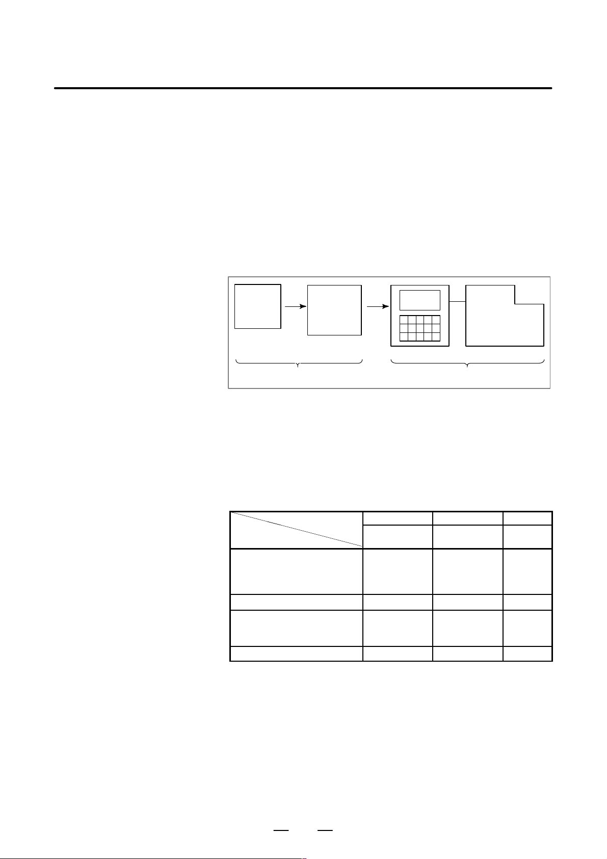
GENERAL1. GENERAL
B–63604EN/01
1.1
GENERAL FLOW OF
OPERATION OF CNC
MACHINE TOOL
When machining the part using the CNC machine tool, first prepare the
program, then operate the CNC machine by using the program.
1) First, prepare the program from a part drawing to operate the CNC
machine tool.
How to prepare the program is described in the Chapter II.
PROGRAMMING.
2) The program is to be read into the CNC system. Then, mount the
workpieces and tools on the machine, and operate the tools according
to the programming. Finally, execute the machining actually.
How to operate the CNC system is described in the Chapter III.
OPERATION.
Part
drawing
CHAPTER II PROGRAMMING CHAPTER III OPERA TION
Part
programming
CNC
MACHINE TOOL
Before the actual programming, make the machining plan for how to
machine the part.
Machining plan
1. Determination of workpieces machining range
2. Method of mounting workpieces on the machine tool
3. Machining sequence in every cutting process
4. Cutting tools and cutting conditions
Decide the cutting method in every cutting process.
Cutting process
Cutting procedure
1. Cutting method
: Rough
Semi
Finish
2. Cutting tools
3. Cutting conditions
: Feedrate
Cutting depth
4. Tool path
1 2 3
End face
cutting
Outer diameter
cutting
Grooving
6
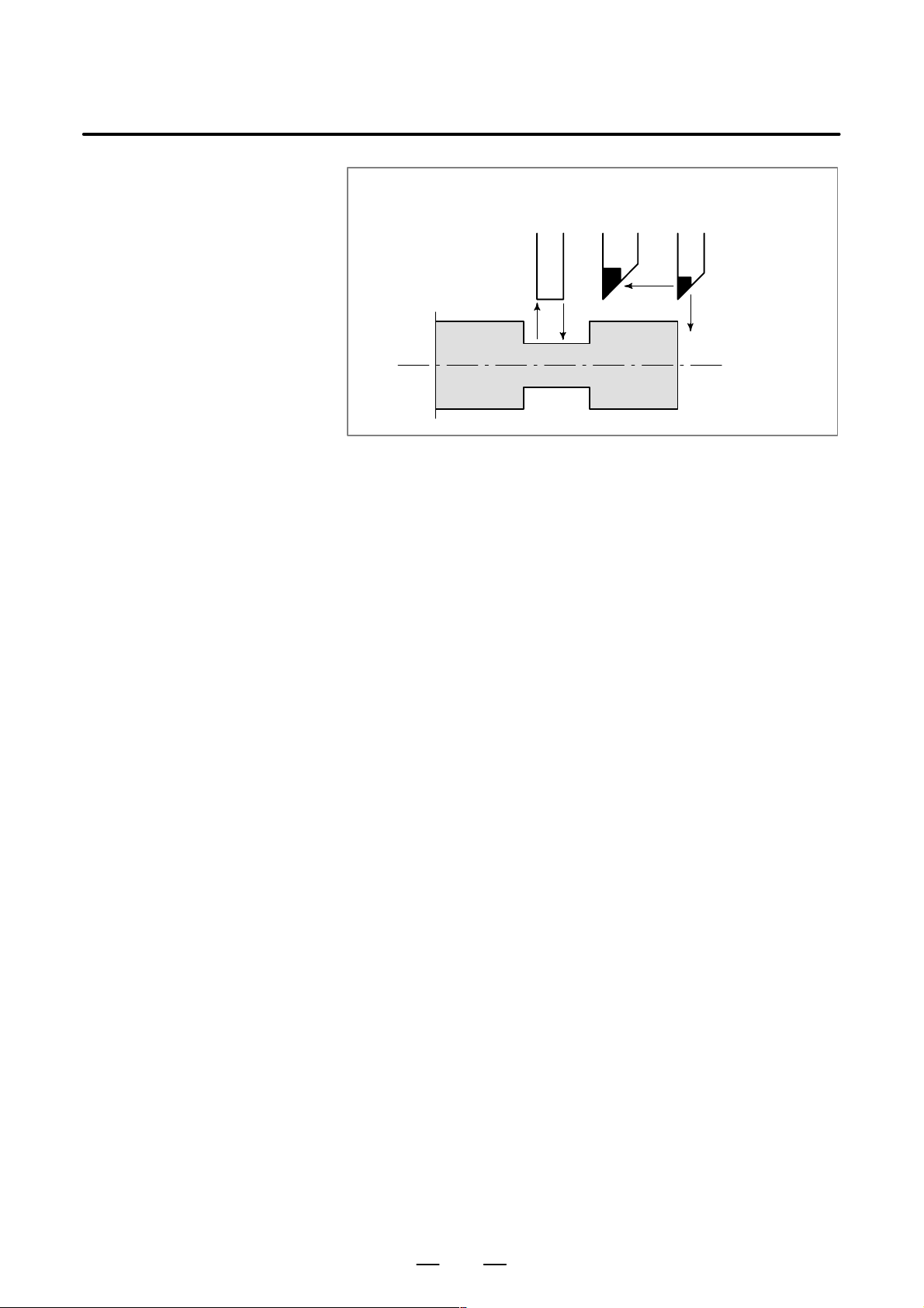
B–63604EN/01
GENERAL
1. GENERAL
Grooving
Outer
diameter
cutting
Workpiece
End
face
cutting
Prepare the program of the tool path and cutting condition according to
the workpiece figure, for each cutting.
7

1.2
CAUTIONS ON
READING THIS
MANUAL
GENERAL1. GENERAL
CAUTION
1 The function of an CNC machine tool system depends not
only on the CNC, but on the combination of the machine
tool, its magnetic cabinet, the servo system, the CNC, the
operator’s panels, etc. It is too difficult to describe the
function, programming, and operation relating to all
combinations. This manual generally describes these from
the stand–point of the CNC. So, for details on a particular
CNC machine tool, refer to the manual issued by the
machine tool builder, which should take precedence over
this manual.
2 Headings are placed in the left margin so that the reader can
easily access necessary information. When locating the
necessary information, the reader can save time by
searching though these headings.
3 This manual describes as many reasonable variations in
equipment usage as possible. It cannot address every
combination of features, options and commands that
should not be attempted.
If a particular combination of operations is not described, it
should not be attempted.
B–63604EN/01
1.3
CAUTIONS ON
V ARIOUS KINDS OF
DATA
CAUTION
Machining programs, parameters, variables, etc. are stored
in the CNC unit internal non–volatile memory. In general,
these contents are not lost by the switching ON/OFF of the
power. However, it is possible that a state can occur where
precious data stored in the non–volatile memory has to be
deleted, because of deletions from a maloperation, or by a
failure restoration. In order to restore rapidly when this kind
of mishap occurs, it is recommended that you create a copy
of the various kinds of data beforehand.
8

II. PROGRAMMING


B–63604EN/01
1
GENERAL
PROGRAMMING
1. GENERAL
11
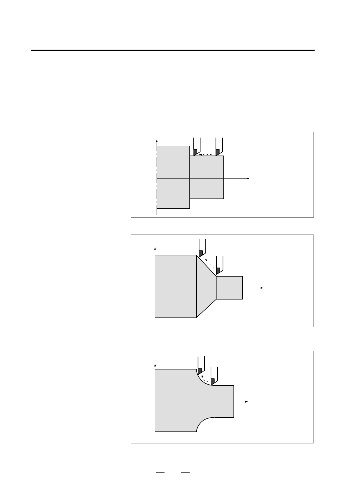
PROGRAMMING1. GENERAL
B–63604EN/01
1.1
TOOL MOVEMENT
ALONG WORKPIECE
P ARTS FIGURE–
INTERPOLATION
Explanations
D Tool movement along a
straight line
The tool moves along straight lines and arcs constituting the workpiece
parts figure (See II–4).
X
Tool
Workpiece
Fig.1.1 (a) Tool movement along the straight line which is parallel to Z–axis
Program
G01 Z…;
Z
D Tool movement along an
arc
X
Tool
Workpiece
Fig.1.1 (b) T ool movement along the taper line
X
Workpiece
Tool
Program
G02X … Z … R … ;
or
G03X … Z … R … ;
Z
Program
G01 X … Z… ;
Z
Fig. 1.1 (c) T ool movement along an arc
12
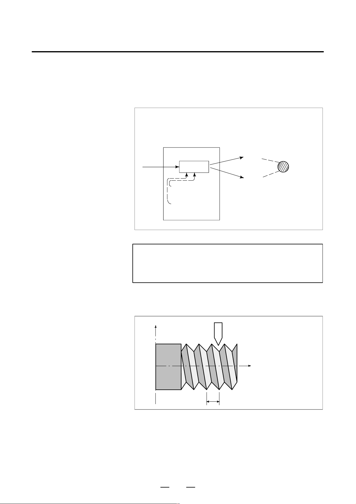
B–63604EN/01
PROGRAMMING
1. GENERAL
The term interpolation refers to an operation in which the tool moves
along a straight line or arc in the way described above.
Symbols of the programmed commands G01, G02, … are called the
preparatory function and specify the type of interpolation conducted in
the control unit.
(a) Movement along straight line
G01 Z__;
X––Z––––;
Control unit
Interpolation
a) Movement
along straight
line
b) Movement
along arc
Fig. 1.1 (d) Interpolation function
(b) Movement along arc
G03X––Z––;
X axis
Y axis
Tool
movement
NOTE
Some machines move workpiece (spindle) instead of tools
but this manual assumes that tools are moved against
workpieces.
D Thread cutting
Threads can be cut by moving the tool in synchronization with spindle
rotation. In a program, specify the thread cutting function by G32.
X
Workpiece
Fig. 1.1 (e) Straight thread cutting
Tool
Z
F
Program
G32Z––F––;
13
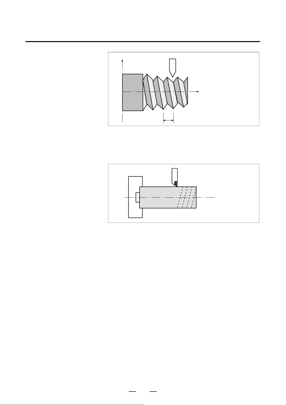
PROGRAMMING1. GENERAL
B–63604EN/01
1.2
FEED–
FEED FUNCTION
X
Workpiece
Fig. 1.1 (f) T aper thread cutting
Tool
Program
G32X––Z––F––;
Z
F
Movement of the tool at a specified speed for cutting a workpiece is called
the feed.
Chuck
Workpiece
Tool
Fig. 1.2 Feed function
Feedrates can be specified by using actual numerics.
For example, the following command can be used to feed the tool 2 mm
while the workpiece makes one turn :
F2.0
The function of deciding the feed rate is called the feed function (See
II–5).
14
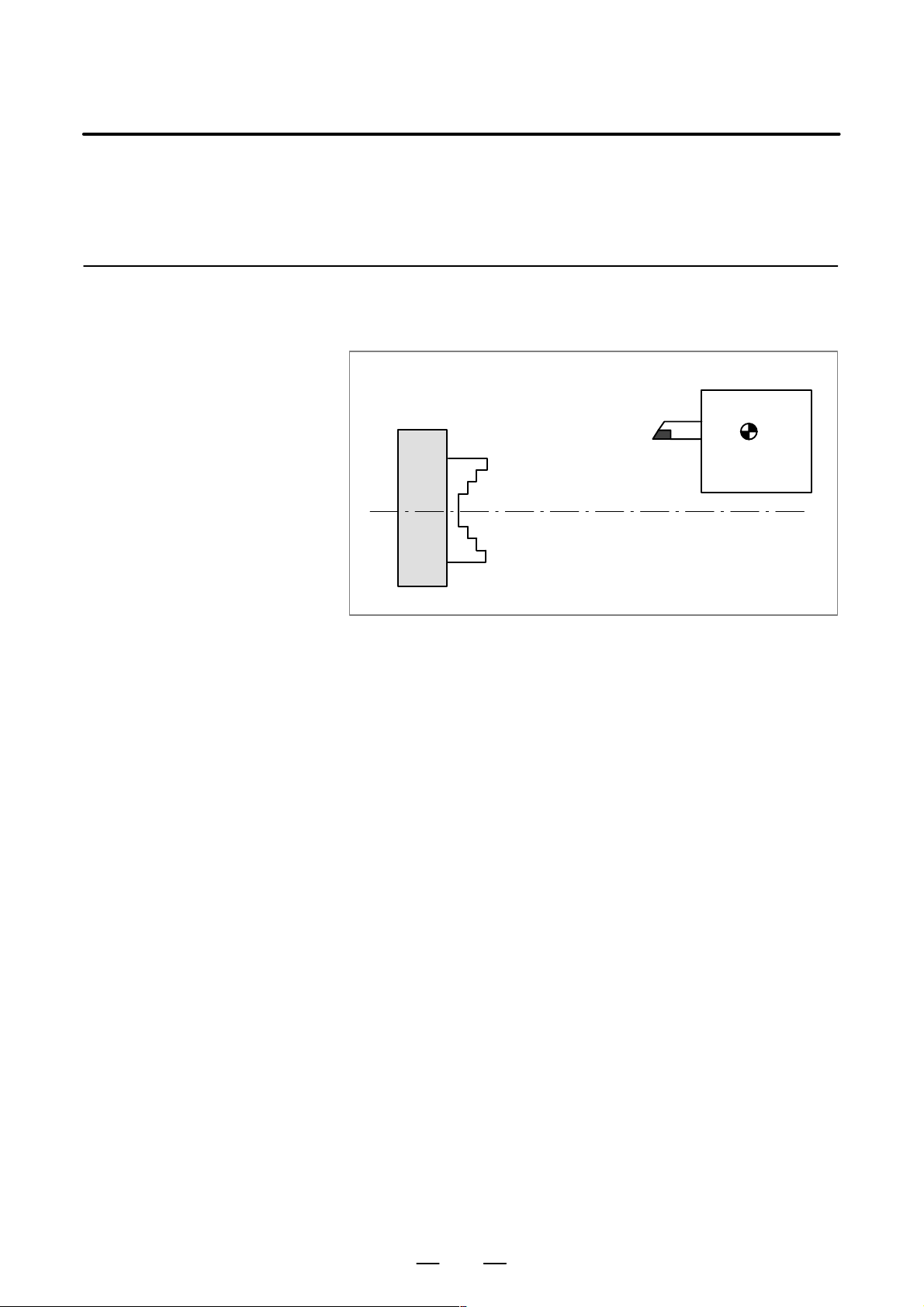
B–63604EN/01
1.3
PART DRAWING AND
TOOL MOVEMENT
PROGRAMMING
1. GENERAL
1.3.1
Reference Position
(Machine–Specific
Position)
Explanations
A CNC machine tool is provided with a fixed position. Normally, tool
change and programming of absolute zero point as described later are
performed at this position. This position is called the reference position.
Tool post
Chuck
Fig. 1.3.1 Reference position
The tool can be moved to the reference position in two ways:
1. Manual reference position return (See III–3.1)
Reference position return is performed by manual button operation.
Reference
position
2. Automatic reference position return (See II–6)
In general, manual reference position return is performed first after
the power is turned on. In order to move the tool to the reference
position for tool change thereafter, the function of automatic
reference position return is used.
15
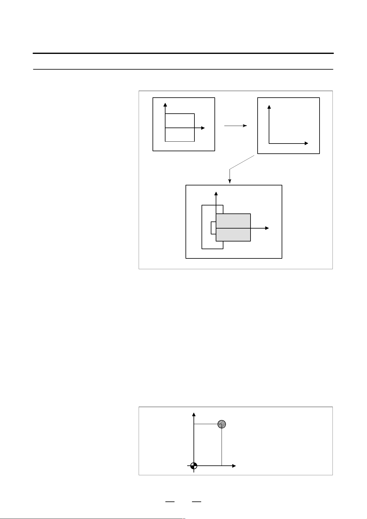
1.3.2
Coordinate System on
Part Drawing and
Coordinate System
Specified by CNC –
Coordinate System
PROGRAMMING1. GENERAL
X
Part drawing
B–63604EN/01
X
Program
Z
Z
Coordinate system
CNC
Command
X
Workpiece
Explanations
D Coordinate system
Z
Machine tool
Fig. 1.3.2 (a) Coordinate system
The following two coordinate systems are specified at different locations:
(See II–7)
1. Coordinate system on part drawing
The coordinate system is written on the part drawing. As the program
data, the coordinate values on this coordinate system are used.
2. Coordinate system specified by the CNC
The coordinate system is prepared on the actual machine tool. This
can be achieved by programming the distance from the current
position of the tool to the zero point of the coordinate system to be
set.
X
230
300
Program
zero point
Fig. 1.3.2 (b) Coordinate system specified by the CNC
Present tool position
Distance to the zero point of a coordinate system to be set
Z
16
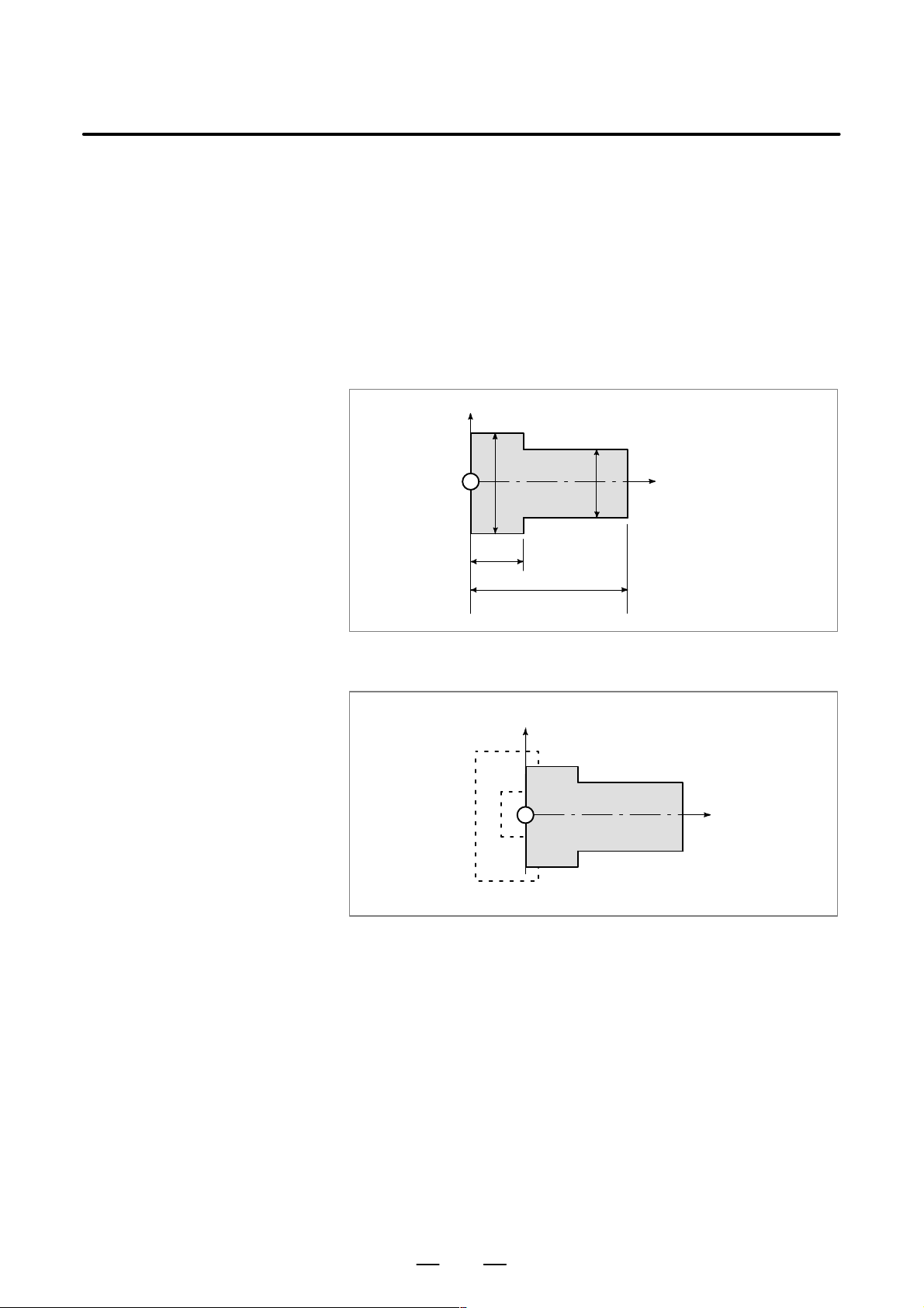
B–63604EN/01
PROGRAMMING
1. GENERAL
The tool moves on the coordinate system specified by the CNC in
accordance with the command program generated with respect to the
coordinate system on the part drawing, and cuts a workpiece into a shape
on the drawing.
Therefore, in order to correctly cut the workpiece as specified on the
drawing, the two coordinate systems must be set at the same position.
D Methods of setting the
two coordinate systems
in the same position
The following method is usually used to define two coordinate systems
at the same location.
1. When coordinate zero point is set at chuck face
X
Workpiece
60
40
150
Fig. 1.3.2 (c) Coordinates and dimensions on part drawing
X
40
Z
Workpiece
Z
Fig. 1.3.2 (d) Coordinate system on lathe as specified by CNC
(made to coincide with the coordinate system on part drawing)
17
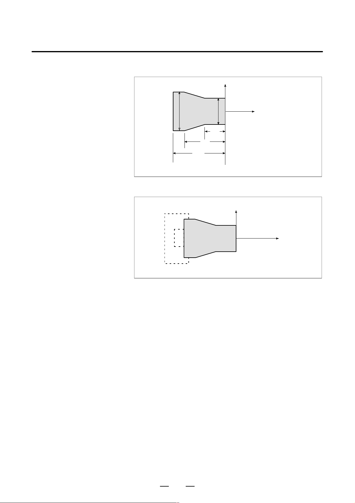
PROGRAMMING1. GENERAL
2. When coordinate zero point is set at work end face.
X
B–63604EN/01
Workpiece
60
100
Fig. 1.3.2 (e) Coordinates and dimensions on part drawing
Workpiece
80
30
30
Z
X
Z
Fig. 1.3.2 (f) Coordinate system on lathe as specified by CNC
(made to coincide with the coordinate system on part drawing)
18
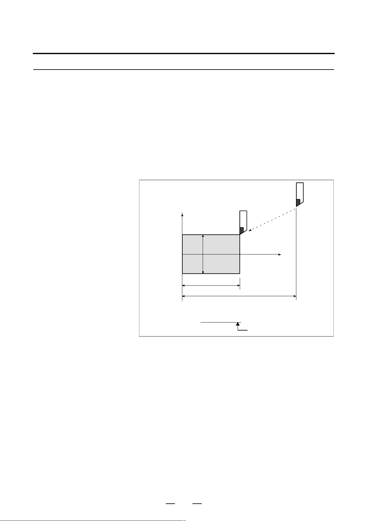
B–63604EN/01
1.3.3
How to Indicate
Command Dimensions
for Moving the Tool –
Absolute, Incremental
Commands
PROGRAMMING
1. GENERAL
Explanations
D Absolute command
Methods of command for moving the tool can be indicated by absolute
or incremental designation (See II–8.1).
The tool moves to a point at “the distance from zero point of the
coordinate system” that is to the position of the coordinate values.
Tool
X
Workpiece
φ30
70
Command specifying movement from point A to point B
G90X30.0Z70.0;
B
110
A
Z
Fig. 1.3.3 (a) Absolute command
19
Coordinates of point B
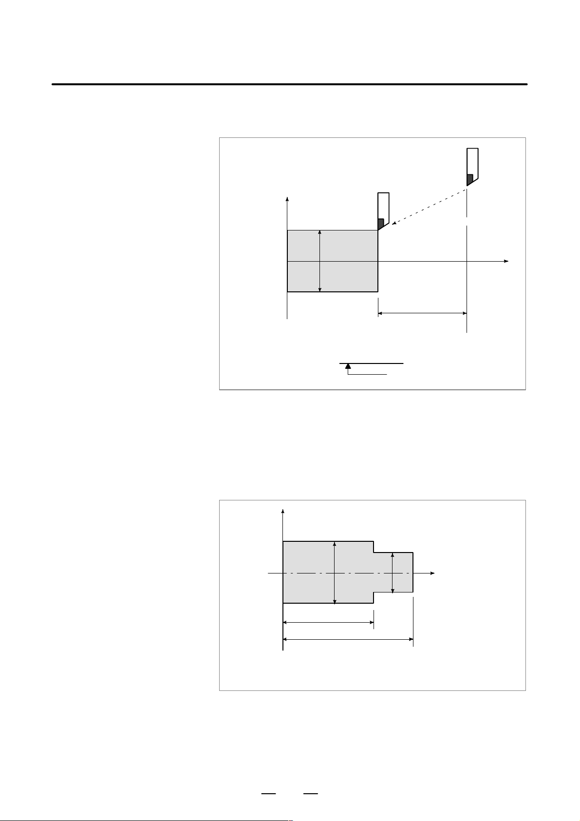
PROGRAMMING1. GENERAL
B–63604EN/01
D Incremental command
Specify the distance from the previous tool position to the next tool
position.
Tool
A
X
φ60
B
Z
φ30
40
Command specifying movement from point A to point B
U–30.0W–40.0
Distance and direction for
movement along each axis
D Diameter programming /
radius programming
Fig. 1.3.3 (b) Incremental command
Dimensions of the X axis can be set in diameter or in radius. Diameter
programming or radius programming is employed independently in each
machine.
1. Diameter programming
In diameter programming, specify the diameter value indicated on the
drawing as the value of the X axis.
X
B
φ30
A
Z
Workpiece
φ40
60
80
Coordinate values of points A and B
A(30.0, 80.0), B(40.0, 60.0)
Fig. 1.3.3 (c) Diameter programming
20
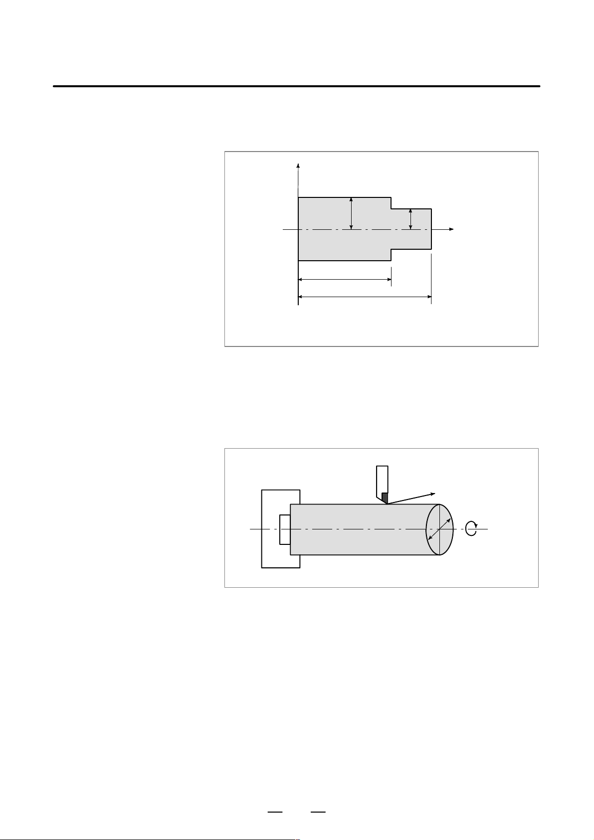
B–63604EN/01
PROGRAMMING
1. GENERAL
2. Radius programming
In radius programming, specify the distance from the center of the
workpiece, i.e. the radius value as the value of the X axis.
X
B
20
Workpiece
60
80
Coordinate values of points A and B
A(15.0, 80.0), B(20.0, 60.0)
Fig. 1.3.3 (d) Radius programming
A
15
Z
1.4
CUTTING SPEED –
SPINDLE SPEED
FUNCTION
Examples
The speed of the tool with respect to the workpiece when the workpiece
is cut is called the cutting speed.
As for the CNC, the cutting speed can be specified by the spindle speed
–1
in min
unit.
Tool
Workpiece
Fig. 1.4 Cutting speed
V: Cutting speed
v m/min
φD
N min
–1
<When a workpiece 200 mm in diameter should be machined at
a cutting speed of 300 m/min. >
–1
The spindle speed is approximately 478 min
, which is obtained from
N=1000v/πD. Hence the following command is required:
S478 ;
Commands related to the spindle speed are called the spindle speed
function (See II–9).
The cutting speed v (m/min) can also be specified directly by the speed
value. Even when the workpiece diameter is changed, the CNC changes
the spindle speed so that the cutting speed remains constant.
This function is called the constant surface speed control function
(See II–9.3).
21
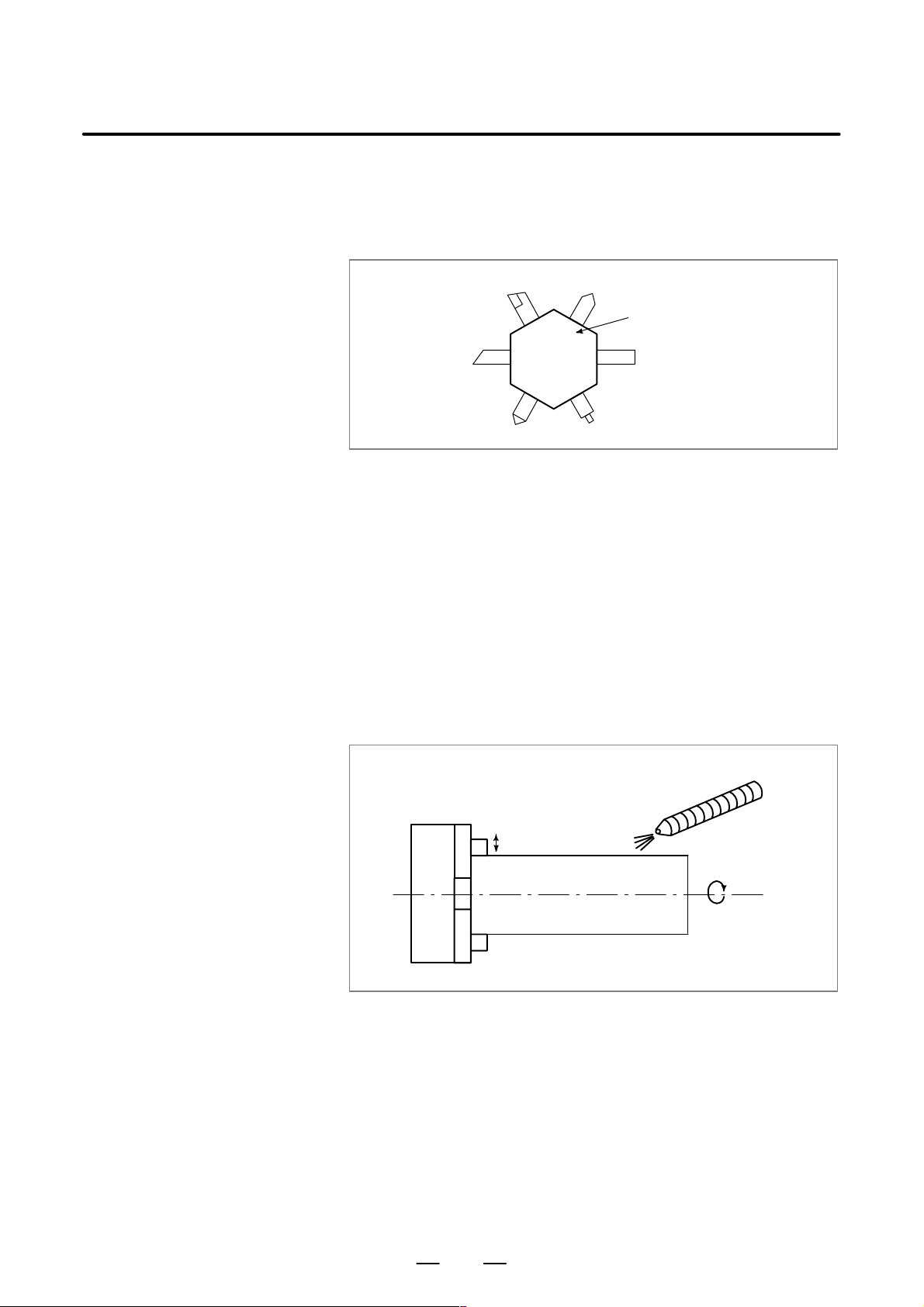
PROGRAMMING1. GENERAL
B–63604EN/01
1.5
SELECTION OF
TOOL USED FOR
VARIOUS
MACHINING – TOOL
FUNCTION
Examples
When drilling, tapping, boring, milling or the like, is performed, it is
necessary to select a suitable tool. When a number is assigned to each tool
and the number is specified in the program, the corresponding tool is
selected.
Tool number
01
06
02 05
04
03
Fig. 1.5 T ool used for various machining
<When No.01 is assigned to a roughing tool>
When the tool is stored at location 01 of the tool post, the tool can be
selected by specifying T0101.
This is called the tool function (See II–10).
Tool post
1.6
COMMAND FOR
MACHINE
OPERATIONS –
MISCELLANEOUS
FUNCTION
When machining is actually started, it is necessary to rotate the spindle,
and feed coolant. For this purpose, on–off operations of spindle motor and
coolant valve should be controlled (See II–11).
Coolant on/off
Chuck open/close
Workpiece
Fig. 1.6 Command for machine operations
The function of specifying the on–off operations of the components of the
machine is called the miscellaneous function. In general, the function is
specified by an M code.
For example, when M03 is specified, the spindle is rotated clockwise at
the specified spindle speed.
CW spindle rotation
22
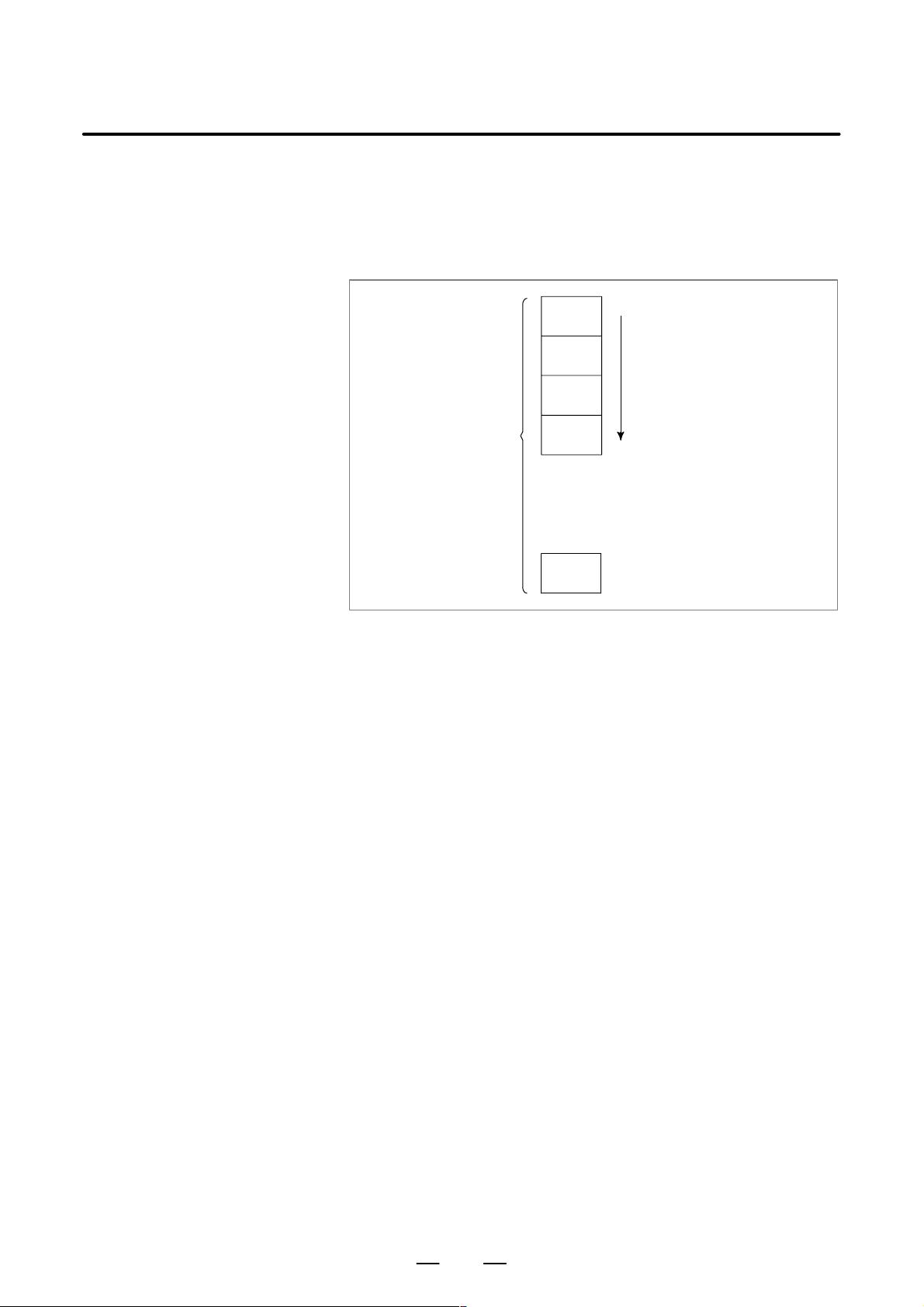
B–63604EN/01
PROGRAMMING
1. GENERAL
1.7
PROGRAM
CONFIGURATION
A group of commands given to the CNC for operating the machine is
called the program. By specifying the commands, the tool is moved along
a straight line or an arc, or the spindle motor is turned on and off.
In the program, specify the commands in the sequence of actual tool
movements.
Block
Block
Tool movement sequence
Block
Program
Block
⋅
⋅
⋅
⋅
Block
Fig. 1.7 (a) Program configuration
A group of commands at each step of the sequence is called the block.
The program consists of a group of blocks for a series of machining. The
number for discriminating each block is called the sequence number, and
the number for discriminating each program is called the program number
(See II–12).
23

PROGRAMMING1. GENERAL
B–63604EN/01
Explanations
D Block
The block and the program have the following configurations.
1 block
N fffff G ff Xff.f Zfff.f M ff S ff T ff ;
Sequence
number
Preparatory
function
Dimension word Miscel-
laneous
function
Fig. 1.7 (b) Block configuration
Spindle
function
Tool
function
End of
block
A block begins with a sequence number that identifies that block and ends
with an end–of–block code.
This manual indicates the end–of–block code by ; (LF in the ISO code and
CR in the EIA code).
The contents of the dimension word depend on the preparatory function.
In this manual, the portion of the dimension word may be represent as IP_.
D Program
;
Offff;
⋅
⋅
⋅
M30 ;
Fig. 1.7 (c) Program configuration
Program number
Block
Block
Block
⋅
⋅
⋅
End of program
Normally, a program number is specified after the end–of–block (;) code
at the beginning of the program, and a program end code (M02 or M30)
is specified at the end of the program.
24
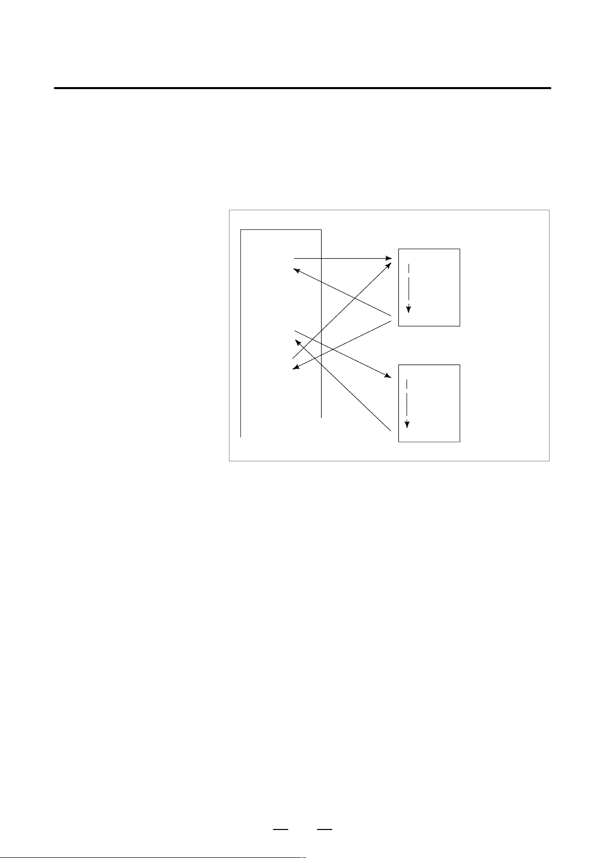
B–63604EN/01
PROGRAMMING
1. GENERAL
D Main program and
subprogram
When machining of the same pattern appears at many portions of a
program, a program for the pattern is created. This is called the
subprogram. On the other hand, the original program is called the main
program. When a subprogram execution command appears during
execution of the main program, commands of the subprogram are
executed. When execution of the subprogram is finished, the sequence
returns to the main program.
Main program
⋅
⋅
M98P1001
⋅
⋅
⋅
M98P1002
⋅
⋅
⋅
M98P1001
⋅
⋅
Subprogram #1
O1001
M99
Subprogram #2
O1002
Program for
hole #1
Program for
hole #2
⋅
M99
25

1.8
COMPENSATION
FUNCTION
Explanations
PROGRAMMING1. GENERAL
B–63604EN/01
D Machining using the end
of cutter – Tool length
compensation function
Usually, several tools are used for machining one workpiece. The tools
have different tool length. It is very troublesome to change the program
in accordance with the tools.
Therefore, the length of each tool used should be measured in advance.
By setting the difference between the length of the standard tool and the
length of each tool in the CNC (data display and setting : see III–11),
machining can be performed without altering the program even when the
tool is changed. This function is called tool length compensation.
Workpiece
Standard
tool
Rough
cutting
tool
Fig. 1.8 Tool offset
Finishing
tool
Grooving
tool
Thread
cutting
tool
26
 Loading…

![]()

Инструкция по эксплуатации станка ЧПУ на русском языке на базе системы Fanuc 16, 18i, 21i. Инструкции в редактируемом формате DOC для программы microsoft word
Прикрепленные файлы
Последние добавленные макеты

Пригласительное на свадьбу
Подставка для книг, тарелок и другой сувенирной продукции
Значки для украшения георгиевских лент
Звезды с гергиевской лентой
Варианты написания слова «Победа»
Стол студийный
- Файлы
- Академическая и специальная литература
- Машиностроение и металлообработка
- Металлорежущие станки
- ГПС и станки с ЧПУ
- Нормативные документы
-
Файл формата
pdf - размером 5,83 МБ
- Добавлен пользователем vanka_S 03.01.2014 12:02
- Описание отредактировано 21.05.2017 08:49

Автор: неизвестен; выходные данные: не указаны. Код документа B-63604RU/01, 809 стр. В руководстве изложены общие сведения, программирование, работа и техобслуживание стойки ЧПУ.
Предназначено для операторов и наладчиков ЧПУ (эксплуатационного персонала), а также для любознательных в ознакомительных целях.
- Чтобы скачать этот файл зарегистрируйтесь и/или войдите на сайт используя форму сверху.
- Регистрация
- Узнайте сколько стоит уникальная работа конкретно по Вашей теме:
- Сколько стоит заказать работу?
|
Руководство оператора Fanuc 21i/210i TB (3 и 4 тома)
Добавлять комментарии могут только зарегистрированные пользователи. [ Регистрация | Вход ] |
CNC Manual/Fanuc/Fanuc 21i/Fanuc 21i Operator Manual