- Manuals
- Brands
- Festo Manuals
- Controller
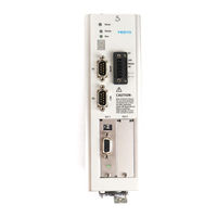
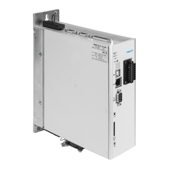
- CMMP-AS-C5-3A
Manuals and User Guides for Festo CMMP-AS-C5-3A. We have 2 Festo CMMP-AS-C5-3A manuals available for free PDF download: Mounting And Installation Manual, Brief Overview
Festo CMMP-AS-C5-3A Mounting And Installation Manual (110 pages)
Type CMMP-AS-3A….
Motorcontroller CMMP…
Brand: Festo
|
Category: Controller
|
Size: 11.8 MB
Table of Contents
-
Table of Contents
5
-
1 General Data
10
-
Documentation
10
-
Scope of Delivery
11
-
-
2 Safety Instructions for Electric Drives and Controllers
12
-
Icons Used
12
-
General Information
12
-
Danger through Incorrect Use
14
-
Safety Instructions
15
-
General Safety Information
15
-
Safety Instructions for Assembly and Maintenance
16
-
Protection against Touching Electric Components
18
-
Protection by Low Voltage (PELV) against Electric Shock
20
-
Protection from Dangerous Movements
20
-
Protection against Touching Hot Components
21
-
Protection When Handling and Assembling
22
-
-
-
3 Product Description
23
-
General Data
23
-
Switch-On Sequence
26
-
-
Power Supply
27
-
Single-Phase AC Supply with Active PFC
27
-
Intermediate Circuit Coupling, DC Power Supply
29
-
Mains Fuse
29
-
-
Brake Chopper
29
-
Communication Interfaces
30
-
Festo Profile for Handling and Positioning (FHPP)
30
-
RS232 Interface
31
-
CAN Bus
31
-
Profibus
31
-
Devicenet
32
-
Sercos
32
-
I/O Functions and Device Control
33
-
-
-
4 Function Overview
35
-
Motors
35
-
Synchronous Servo Motors
35
-
Linear Motors
35
-
-
Functions of the CMMP-AS Servo Positioning Controller
35
-
Compatibility
35
-
Pulse Width Modulation (PWM)
36
-
Setpoint Management
36
-
Controlled Torque Mode
37
-
Controlled Speed Mode
37
-
Torque-Limited Speed Control
38
-
Synchronisation to External Clock Sources
38
-
Load Torque Compensation for Vertical Axes
38
-
Positioning and Position Control
38
-
4.2.10 Synchronisation, Electrical Gearboxes
40
-
4.2.11 Brake Management
40
-
-
Positioning Control
40
-
Overview
40
-
Relative Positioning
41
-
Absolute Positioning
42
-
Motion Profile Generator
42
-
Homing Run
42
-
Positioning Sequences
43
-
Optional Stop Input
44
-
Contour Control with Linear Interpolation
44
-
Time-Synchronised Multi-Axis Positioning
45
-
-
-
5 Functional Safety Engineering
46
-
General Information and Intended Use
46
-
Integrated «Safe Standstill» Function
48
-
General Information / Description of «Safe Standstill
48
-
Secure Stopping Brake Control
50
-
Functional Method / Timing
51
-
Typical Applications
54
-
-
-
6 Mechanical Installation
59
-
Important Instructions
59
-
Device View
61
-
Assembly
64
-
-
7 Electrical Installation
65
-
Connector Pin Assignments
65
-
Entire CMMP-AS System
66
-
Connection: Power Supply [X9]
68
-
Layout on Device [X9]
68
-
Counterplug [X9]
68
-
Pin Assignments [X9]
68
-
Calculating the Required Braking Resistor
69
-
-
Connection: Motor [X6]
69
-
Layout on Device [X6]
69
-
Counterplug [X6]
69
-
Pin Assignments [X6]
69
-
-
Connection: I/O Communication [X1]
70
-
Layout on Device [X1]
71
-
Counterplug [X1]
71
-
Pin Assignments [X1]
72
-
Type and Layout of Cable [X1]
72
-
Connection Notes [X1]
73
-
-
Connection: Safe Standstill [X3]
74
-
Layout on Device [X3]
75
-
Counterplug [X3]
75
-
Pin Assignments [X3]
75
-
-
Connection: Resolver [X2A]
75
-
Layout on Device [X2A]
75
-
Counterplug [X2A]
75
-
Pin Assignments [X2A]
75
-
-
Connection: Encoder [X2B]
76
-
Layout on Device [X2B]
76
-
Counterplug [X2B]
76
-
-
Connection: Increment Encoder Input [X10]
77
-
Layout on Device [X10]
77
-
Counterplug [X10]
77
-
Pin Assignments [X10]
77
-
Type and Layout of Cable [X10]
77
-
Connection Notes [X10]
77
-
-
Connection: Incremental Encoder Output [X11]
78
-
Layout on Device [X11]
78
-
Counterplug [X11]
78
-
Pin Assignments [X11]
78
-
-
Connection: CAN Bus [X4]
78
-
Layout on Device [X4]
78
-
Counterplug [X4]
79
-
Pin Assignments [X4]
79
-
Connection Notes [X4]
79
-
-
Connection: RS232/COM [X5]
80
-
Layout on Device [X5]
80
-
Counterplug [X5]
80
-
Pin Assignments [X5]
81
-
-
Instructions on Safe and EMC-Compliant Installation
82
-
7.13.1 Explanations and Terms
82
-
7.13.2 Connection Instructions
82
-
7.13.3 General Information on EMC
82
-
7.13.4 EMC Areas: First and Second Environments
83
-
7.13.5 EMC-Compliant Wiring
84
-
7.13.6 Operation with Long Motor Cables
84
-
7.13.7 ESD Protection
85
-
-
-
8 Startup
86
-
General Connection Instructions
86
-
Tools / Material
86
-
Connecting the Motor
86
-
Connect the CMMP-AS Servo Positioning Controller to the Power Supply
87
-
Connecting a PC
87
-
Checking Readiness for Operation
87
-
-
9 Service Functions and Error Messages
89
-
Protective and Service Functions
89
-
Overview
89
-
Overload Current and Short-Circuit Monitoring
89
-
Overvoltage Monitoring for the Intermediate Circuit
89
-
Temperature Monitoring for the Heat Sink
89
-
Motor Monitoring
90
-
I²T Monitoring
90
-
Power Monitoring for the Brake Chopper
90
-
L²T Monitoring of the PFC Stage
90
-
Commissioning Status
90
-
9.1.10 Operating Time Counter
91
-
-
Operating Mode and Error Messages
91
-
Operating Mode and Error Display
91
-
Error Messages
91
-
Acknowledge Error
100
-
-
-
Technical Specifications
101
-
Operation and Display Components
102
-
Power Supply [X9]
102
-
Motor Connection [X6]
104
-
Angle Encoder Connections [X2A] and [X2B]
104
-
Resolver Connection [X2A]
104
-
Encoder Connection [X2B]
105
-
Encoder Connection [X2B] for EMMS-AS
105
-
-
Communication Interfaces
106
-
Rs232 [X5]
106
-
CAN Bus [X4]
106
-
A.5 Communication Interfaces
106
-
I/O Interface [X1]
107
-
A.5.3 I/O Interface [X1]
107
-
Increment Encoder Input [X10]
108
-
Incremental Encoder Output [X11]
108
-
-
-
Glossary
109
Advertisement
Festo CMMP-AS-C5-3A Brief Overview (86 pages)
Motor controller
Brand: Festo
|
Category: Controller
|
Size: 2 MB
Advertisement
Related Products
-
Festo CMMP-AS-C5-3A-M0
-
Festo CMMP-AS-C5-11A-P3-M0
-
Festo CMMP-AS-C5-3A-M3
-
Festo CMMP-AS-C5-11A-P3-M3
-
Festo CMMP-AS-C5-11A-P3-M0-C1
-
Festo CMMP-AS-C5-11A-P3-M3-C1
-
Festo CMMP-AS-C5-3A-M0-C1
-
Festo CMMP-AS-C5-3A-M3-C1
-
Festo CMMP-AS-C5-11A
-
Festo CMMP-AS-C10-11A-P3-M0
Festo Categories
Industrial Equipment
Control Unit
Controller
Touch terminals
DC Drives
More Festo Manuals
-
Contents
-
Table of Contents
-
Bookmarks
Quick Links
Motor controller
CMMP-AS-…-M0
Description
Mounting and
installation
For motor controller
CMMP-AS-…-M0
8049674
1511c
Related Manuals for Festo CMMP-AS-C5-3A-M0
Summary of Contents for Festo CMMP-AS-C5-3A-M0
-
Page 1
Motor controller CMMP-AS-…-M0 Description Mounting and installation For motor controller CMMP-AS-…-M0 8049674 1511c… -
Page 2
Text designations: • Activities that may be carried out in any order 1. Activities that should be carried out in the order stated – General lists è Result of an action/References to more detailed information Festo – GDCP-CMMP-M0-HW-EN – 1511c –… -
Page 3: Table Of Contents
…………Festo – GDCP-CMMP-M0-HW-EN – 1511c – English…
-
Page 4
…………Festo – GDCP-CMMP-M0-HW-EN – 1511c – English… -
Page 5
…………… . Festo – GDCP-CMMP-M0-HW-EN – 1511c – English… -
Page 6: Instructions On This Documentation
0 … 1000 Hz 2.5 A Degree of protection IP10/20 Max. ambient temperature 40 °C Tab. 1 Rating plate example CMMP-AS-C2-3A-M0 Service Please consult your regional Festo contact if you have any technical problems. Specified standards/directives Issue status 2006/42/EC EN 60204-1:2006-06/A1:2009-02 2006/95/EC EN 50178:1997-10 2004/108/EC…
-
Page 7
2.5 A 10 A Input voltage 100 … 230 V AC 3x 230 … 480 V AC 11 A Number of phases – 1-phase 3-phase Number of slots Without slot Fig. 1 Type codes Festo – GDCP-CMMP-M0-HW-EN – 1511c – English… -
Page 8: Documentation
AS-…-M0 with the integrated safety function STO. Help for the FCT plug-in CMMP-AS User interface and functions of the CMMP-AS plug-in for the Festo Configuration Tool è www.festo.com/sp. Tab. 5 Documentation on the motor controller CMMP-AS-…-M0 Festo – GDCP-CMMP-M0-HW-EN – 1511c – English…
-
Page 9: Safety And Requirements For Product Use
– Perform a risk assessment in accordance with the EC machinery directive. – Based on this risk assessment, design the safety system for the entire machine, taking into account all integrated components. This also includes the electric drives. – Bypassing safety equipment is impermissible. Festo – GDCP-CMMP-M0-HW-EN – 1511c – English…
-
Page 10: Protection Against Electric Shock Through Protective Extra-Low Voltage (Pelv)
Note In the event of damage caused by unauthorised manipulation or other than intended use, the guarantee is invalidated and the manufacturer is not liable for damages. Festo – GDCP-CMMP-M0-HW-EN – 1511c – English…
-
Page 11: Requirements For Product Use
Standards and test values, which the product complies with and fulfils, can be found in the “Technical data” section (è Appendix A). The product-relevant EU directives can be found in the declaration of conformity. Certificates and declaration of conformity on this product can be found at è www.festo.com/sp. Festo – GDCP-CMMP-M0-HW-EN – 1511c – English…
-
Page 12
– The technical data in this documentation may show values deviating from this. Certain configurations of earlier revisions of the product have been certified by Underwriters Laborator ies Inc. (UL) for the USA. These are marked as follows: UL Listing Mark for the United States Festo – GDCP-CMMP-M0-HW-EN – 1511c – English… -
Page 13: Product Overview
– Motor controller CMMP-AS-…-M0 – Motor with motor and encoder cables A Windows PC with USB or Ethernet connection is required for parametrisation. Observe the instructions regarding mains fuses in è Chapter 4. Festo – GDCP-CMMP-M0-HW-EN – 1511c – English…
-
Page 14: Scope Of Delivery
Complete structure CMMP-AS-…-M0 with motor and PC Scope of delivery The delivery includes: Scope of delivery Motor controller CMMP-AS-…-M0 Operator package Brief description Assortment of plugs NEKM-C-7, NEKM-C-8 Tab. 2.1 Scope of delivery Festo – GDCP-CMMP-M0-HW-EN – 1511c – English…
-
Page 15: Device View
Ethernet interface [X18] Activation of firmware download [S3] USB interface [X19] SD-/MMC card slot [M1] 7-segment display Activation of CANopen terminating resistor Reset button [S2] LEDs Fig. 2.2 Motor controller CMMP-AS-…-M0: Front view Festo – GDCP-CMMP-M0-HW-EN – 1511c – English…
-
Page 16
Product overview PE connection Incremental encoder output [X11] I/O communication [X1] Power supply [X9] Incremental encoder input [X10] Fig. 2.3 Motor controller CMMP-AS-…-3A-M0: Top view Festo – GDCP-CMMP-M0-HW-EN – 1511c – English… -
Page 17
Product overview PE connection Incremental encoder output [X11] I/O communication [X1] Power supply [X9] Incremental encoder input [X10] Fig. 2.4 Motor controller CMMP-AS-…-11A-P3-M0: Top view Festo – GDCP-CMMP-M0-HW-EN – 1511c – English… -
Page 18
Product overview Spring-loaded terminal connection for the Connection for the resolver [X2A] outer shield of the motor cable Connection for the encoder [X2B] Motor connection [X6] Fig. 2.5 Motor controller CMMP-AS-…-M0: Bottom view Festo – GDCP-CMMP-M0-HW-EN – 1511c – English… -
Page 19: Mechanical Installation
We wish to point out that excessive heating can lead to premature aging and/or damage to the device. With high thermal stress on the mo tor controller CMMP-AS-…-M0, a mounting distance (è Fig. 3.2) is recommended! Festo – GDCP-CMMP-M0-HW-EN – 1511c – English…
-
Page 20: Mounting
The clips are part of the radiator profile, ensuring an optimal heat transfer to the mounting plate. Please use size M5 screws to attach the motor controller CMMP-AS-…-M0. Festo – GDCP-CMMP-M0-HW-EN – 1511c – English…
-
Page 21
Motor controller CMMP-AS-…-M0: Mounting plate CMMP-AS-… -3A-M0 [mm] 207 248 202 12.5 10.5 66 30.7 10 -11A-P3-M0 [mm] 247 297 252 12.5 10.5 79 37.5 10 Tab. 3.1 Motor controller CMMP-AS-…-M0: Dimensions table Festo – GDCP-CMMP-M0-HW-EN – 1511c – English… -
Page 22
CMMP-AS-…-11A-P3-M0 [mm] 1) An installation clearance of 150 mm underneath the device is recommended for optimum wiring of the motor or encoder cable! Tab. 3.2 Motor controller CMMP-AS-…-M0: Mounting distance and installation clearance Festo – GDCP-CMMP-M0-HW-EN – 1511c – English… -
Page 23: Electrical Installation
(RCD) or an error current monitoring device (RCM) is used to protect against direct or indirect contact, only the Type B kind of RCD or RCM is permitted on the power supply side of this product. Festo – GDCP-CMMP-M0-HW-EN – 1511c – English…
-
Page 24
• Before installation: Earth the system parts and use appropriate ESD equipment (e.g. shoes, earthing straps etc.). • After installation: Seal unassigned Sub-D plug connectors with protective caps (available at authorized dealers). • Observe the handling specifications for electrostatically sensitive devices. Festo – GDCP-CMMP-M0-HW-EN – 1511c – English… -
Page 25: Allocation Of The Plug Connectors
24V+ 24 V DC supply GND24V Connection for the outer screening of the motor cable Encoder/resolver X2A/X2B Encoder /Resolver Angle encoder Fig. 4.1 CMMP-AS-…-3A-M0: Single-phase connection to the supply voltage and the motor Festo – GDCP-CMMP-M0-HW-EN – 1511c – English…
-
Page 26
24V+ 24 V DC supply GND24V Connection for the outer screening of the motor cable X2A/X2B Encoder/ Resolver Angle encoder Fig. 4.2 CMMP-AS-…-3A-M0: Dual-phase connection L1/L2 to the supply voltage and the motor Festo – GDCP-CMMP-M0-HW-EN – 1511c – English… -
Page 27
+24 V 24V+ 24 V DC supply GND24V Connection for the outer screening of the motor cable X2A/X2B Encoder/ Resolver Angle encoder Fig. 4.3 CMMP-AS-…-11A-M0: Triple-phase connection to the supply voltage and the motor Festo – GDCP-CMMP-M0-HW-EN – 1511c – English… -
Page 28
If the polarity of the operating voltage connections is reversed, or if the operating voltage is too high or the operating voltage and motor connections are reversed, the motor controller CMMP-AS-…-M0 will be damaged. Festo – GDCP-CMMP-M0-HW-EN – 1511c – English… -
Page 29: Connection: I/O Communication [X1]
Setpoint input 0, differential analogue input AIN0 AGND Reference potential for analogue signals AGND Screening for analogue signals, AGND 1) Configuration with FCT. Observe not è Abschnitt 4.3.3. Tab. 4.4 Pin assignment: I/O communication [X1] (firmware factory setting) Festo – GDCP-CMMP-M0-HW-EN – 1511c – English…
-
Page 30: Use Analogue Inputs As Digital Inputs
If the digital inputs AIN1 and ANI2 are used as digital inputs, then a ground reference from AGND to GND24 at plug X1 pins 14 and 6 must be established. Note Connecting AGND to GND24 renders the electronics overvoltage protection inoperable. Festo – GDCP-CMMP-M0-HW-EN – 1511c – English…
-
Page 31
DINX DIN9 GND24 DOUT0 +24 V DC 100 mA max! DOUT3 DOUTX GND24 GND24 GND24 Plug housing Fig. 4.4 Basic circuit diagram of connection [X1] Control cable and Sub-D plug connector è www.festo.com/catalogue. Festo – GDCP-CMMP-M0-HW-EN – 1511c – English… -
Page 32: Connection: Resolver [X2A]
The outer screening must always be connected to the PE (plug housing) of the motor controller. The inner screenings must be placed on one side on the motor controller CMMP-AS-…-M0 on PIN3 of [X2A]. Festo – GDCP-CMMP-M0-HW-EN – 1511c – English…
-
Page 33: Connection: Encoder [X2B]
1) Heidenhain encoder: A=SIN_Z0; B=COS_Z0, C=SIN_Z1; D=COS_Z1 Tab. 4.9 Pin assignment: Analogue incremental encoder – optional The outer screening must always be connected to the PE (plug housing) of the motor controller. Festo – GDCP-CMMP-M0-HW-EN – 1511c – English…
-
Page 34
1) Heidenhain encoder: A=SIN_Z0; B=COS_Z0 Tab. 4.10 Pin assignment: Incremental encoder with serial interface, e.g. EnDat – optional The outer screening must always be connected to the PE (plug housing) of the motor controller. Festo – GDCP-CMMP-M0-HW-EN – 1511c – English… -
Page 35
L 120 Ω (differential) from digital incre mental encoder Tab. 4.11 Pin assignment: Digital incremental encoder – optional The outer screening must always be connected to the PE (plug housing) of the motor controller. Festo – GDCP-CMMP-M0-HW-EN – 1511c – English… -
Page 36: Connection: Can Bus [X4]
CAN-GND – Galvanically connected to GND in the motor controller – – Not assigned – – Not assigned – – Not assigned CAN shield – Screening Tab. 4.13 Pin assignment for CAN-interface [X4] Festo – GDCP-CMMP-M0-HW-EN – 1511c – English…
-
Page 37: Cmmp-As
A motor holding brake can be connected to terminals BR+ and BR-. The locking brake is supplied from the logic supply of the motor controller. The maximum output current provided by the CMMP-AS-…-M0 motor controller must be observed. Festo – GDCP-CMMP-M0-HW-EN – 1511c – English…
-
Page 38
High voltages with spark formation are created when inductive direct currents are con nected via relays. For interference suppression, we recommend integrated RC interfer ence suppressors, e.g. from Evox RIFA, designation: PMR205AC6470M022 (RC element with 22 Ω in series with 0.47 μF). Festo – GDCP-CMMP-M0-HW-EN – 1511c – English… -
Page 39: Connection: Voltage Supply [X9]
Supply for control section, holding brake and I/O GND24 V GND24 V DC Reference potential for supply 0V 1) Representation of the contact strip on the motor controller CMMP-AS-…-3A-M0 Tab. 4.17 Pin assignment [X9] – single-phase Festo – GDCP-CMMP-M0-HW-EN – 1511c – English…
-
Page 40: Pin Assignment [X9] — Triple-Phase
1) Representation of the contact strip on the motor controller CMMP-AS-…-11A-P3-M0 Tab. 4.18 Pin assignment [X9] – triple-phase Note The DC power supply must be generated from a max. 230/400 V or a max. 277/480 V grid. Festo – GDCP-CMMP-M0-HW-EN – 1511c – English…
-
Page 41: Mains Fuse
Note Operation with mains line choke is not permissible, since the control circuit could be stimulated to oscillate. Note Operation with isolating transformer is not permissible as no reference potential (N) is available. Festo – GDCP-CMMP-M0-HW-EN – 1511c – English…
-
Page 42
Otherwise, the motor controllers will be damaged due to the resulting voltage at the rectifiers. The maximum number of coupled motor controllers is limited by the power of the sup ply. Pay attention to a symmetrical load of the network here. Festo – GDCP-CMMP-M0-HW-EN – 1511c – English… -
Page 43: Braking Resistor
The motor controller detects the external brake resistance automatically as soon as the intermediate circuit voltage rises above the response threshold (è A.1, Tab. A.6). After that, a connected external brake resistance can also be displayed in the configuration software. Festo – GDCP-CMMP-M0-HW-EN – 1511c – English…
-
Page 44: Connection: Incremental Encoder Input [X10]
Pin assignment X10: Incremental encoder input When connecting two motor controllers in the master-slave mode via [X11] and [X10], the pins 5 (+5 V — auxiliary supply) must not be connected to each other. Festo – GDCP-CMMP-M0-HW-EN – 1511c – English…
-
Page 45: Type And Design Of The Cable [X10]
Up to 32 other controllers can be addressed by one device. When connecting two motor controllers in the master-slave mode via [X11] and [X10], the pins 5 (+5 V — auxiliary supply) must not be connected to each other. Festo – GDCP-CMMP-M0-HW-EN – 1511c – English…
-
Page 46: Fct Interfaces
USB driver for the PC The USB driver package is a component of the FCT installation. The following operating systems are supported through this: – Windows XP from Service Pack 2 – Windows Vista – Windows 7 Festo – GDCP-CMMP-M0-HW-EN – 1511c – English…
-
Page 47: Ethernet Tcp/Ip [X18]
The following services are supported by the Ethernet interface: – TCP/IP – UDP/IP – DNS (ARP and BOOTP) – DHCP – AutoIP – TFTP TFTP must be activated separately in Windows if necessary and a pass rule defined in the Firewall. Festo – GDCP-CMMP-M0-HW-EN – 1511c – English…
-
Page 48
If no IP address can be obtained via the higher-level service, the following service is used. Thus if no address can be obtained via DHCP, first an AutoIP and then a static address is used. Festo – GDCP-CMMP-M0-HW-EN – 1511c – English… -
Page 49: Connection: I/O Interface For Sto [X40]
X40 interface, as depicted in Fig. 4.8. This deactivates the integrated safety function! When using this circuitry for the CMMP-AS-…-M0, safety in the application must be en sured through other appropriate measures. Festo – GDCP-CMMP-M0-HW-EN – 1511c – English…
-
Page 50
0V-B +VDC Integrated safety function STO Driver supply Power output stage in CMMP-AS-…-M0 Motor connection (only one phase shown) Voltage supply Fig. 4.8 Circuitry without use of the safety function – functional principle Festo – GDCP-CMMP-M0-HW-EN – 1511c – English… -
Page 51: Instructions On Safe And Emc-Compliant Installation
CMMP-AS-C5-3A-M0 integrated motor chokes and mains filters, which means that it can CMMP-AS-C5-11A-P3-M0 be operated without additional shielding and filters in most appli CMMP-AS-C10-11A-P3-M0 cations. Tab. 4.26 Mains filter Festo – GDCP-CMMP-M0-HW-EN – 1511c – English…
-
Page 52: Emc Areas: First And Second Environment
EN 61800-3 that is applicable to electric drives. The standard compon ents from the Festo accessories were used for qualification. EMC can only be guaranteed if the motor and encoder or resolver cables from Festo are used and not extended or changed in any other form.
-
Page 53: Emc-Compliant Wiring
– Connect the inner screenings to the pins of the plug connectors provided for the purpose; length maximum 40 mm. – Length of the unscreened wires with self-made cables, maximum 35 mm. – Connect entire screening on the controller side flush to the PE terminal; maximum length 40 mm. Festo – GDCP-CMMP-M0-HW-EN – 1511c – English…
-
Page 54
All PE protective earth conductors must always be connected prior to commissioning for reasons of safety. The regulations of EN 50178 and EN 60204-1 for protective grounding must always be observed during installation! Festo – GDCP-CMMP-M0-HW-EN – 1511c – English… -
Page 55: Operation With Long Motor Cables
A distinction is made between the following separated areas: – Output stage with intermediate circuit and mains input – Control electronics with analogue signal processing – 24 V supply and digital inputs and outputs Festo – GDCP-CMMP-M0-HW-EN – 1511c – English…
-
Page 56: Commissioning
4. Connect encoder cable on the motor side. 5. Insert the Sub-D plug connector into socket [X2A] resolver or [X2B] encoder of the device and tight en the locking screws. 6. Check all plug connectors once again. Festo – GDCP-CMMP-M0-HW-EN – 1511c – English…
-
Page 57: Connect Motor Controller Cmmp-As
5. Make the network power supply connections. 6. Check all plug connectors once again. Connecting a PC 1. Connect PC via USB è 4.11.2 USB [X19] or Ethernet è 4.11.3 Ethernet TCP/IP [X18] to the motor controller. Festo – GDCP-CMMP-M0-HW-EN – 1511c – English…
-
Page 58: Check Operating Status
3. Check all connecting cables. 4. Check that the 24 V power supply is functional. 5. Switch on the power supply again. 6. If still no indicator lights up è Device is defective. Festo – GDCP-CMMP-M0-HW-EN – 1511c – English…
-
Page 59: Service Functions And Diagnostic Messages
The heat sink temperature of the output end stage is measured with a linear temperature sensor. The temperature limit varies between the device performance classes è Tab. A.3 on page 66. A temperature warning is triggered approx. 5 °C below the limit value. Festo – GDCP-CMMP-M0-HW-EN – 1511c – English…
-
Page 60: Monitoring Of The Motor
In addition, the brake chopper is protected by means of overcurrent detection. If a short circuit is detec ted via the braking resistor, the brake chopper controller is switched off. Festo – GDCP-CMMP-M0-HW-EN – 1511c – English…
-
Page 61: Commissioning Status
Service functions and diagnostic messages 6.1.9 Commissioning status Motor controllers sent to Festo for servicing are loaded with other firmware and parameters for testing purposes. Before it is commissioned again at the location of the final customer, the motor controller CMMP- AS-…-M0 must be parametrised.
-
Page 62: 7-Segment Display
Warning message with main index “xx” and sub-index “y”. A warning is shown at least twice on the 7-segments display. 1) Several characters are displayed one after the other. Tab. 6.3 Operating mode and error display Festo – GDCP-CMMP-M0-HW-EN – 1511c – English…
-
Page 63: Acknowledgement Of Error Messages
Diagnostic events that are parameterised as warnings are automatically acknowledged when the cause is no longer present. 6.2.4 Diagnostic messages The significance and their measures for diagnostic messages are summarised in the following chapter: è Chapter A Technical appendix Festo – GDCP-CMMP-M0-HW-EN – 1511c – English…
-
Page 64: Maintenance, Care, Repair And Replacement
– Mounting è Section 3.2. – Electrical installation è Chapter 4. – Commissioning è Chapter 5. 7.3.2 Disposal Observe the local regulations for environmentally appropriate disposal of electronic mod ules. The product is RoHS-compliant. Festo – GDCP-CMMP-M0-HW-EN – 1511c – English…
-
Page 65: A Technical Appendix
1) without plugs, shield screw and screw heads Tab. A.1 Technical data: General Transport and storage CMMP-AS- C2-3A-M0 C5-3A-M0 C5-11A-P3-M0 C10-11A-P3-M0 Temperature [°C] -25 … +70 range Tab. A.2 Technical data: Transport and storage Festo – GDCP-CMMP-M0-HW-EN – 1511c – English…
-
Page 66
Technical data: Logic supply Note With a warm motor and a supply voltage that is too low (outside of tolerance), the mo tor’s brakes cannot open 100%, which can lead to premature wearing of the brake. Festo – GDCP-CMMP-M0-HW-EN – 1511c – English… -
Page 67
Peak power 1000 – Tab. A.5 Technical data: Load voltage Below the nominal power supply voltage, the PFC stage power is linearly reduced. These power charac teristic curves are shown in the following figure. Festo – GDCP-CMMP-M0-HW-EN – 1511c – English… -
Page 68
[kW] Continuous output Braking resistor, external 50 40 Resistance value [Ω] 460 800 Operating voltage [V] 2500 5000 Continuous output Tab. A.6 Technical data for brake resistance Festo – GDCP-CMMP-M0-HW-EN – 1511c – English… -
Page 69
This calculation determines the best values to prevent an overloading of the components. In addition, the length of the motor cable is also incorporated into the calculation in order to protect the mains filters contained in the motor controller è Section 4.13.5. Festo – GDCP-CMMP-M0-HW-EN – 1511c – English… -
Page 70
Maximum output current for maximum time (effective value) Max. output current Max. time Max. output current 13.2 Max. time Max. output current, effective 17.6 Max. time 1) Option with FCT able to be parametrised Tab. A.11 Output data CMMP-AS-C5-3A-M0 Festo – GDCP-CMMP-M0-HW-EN – 1511c – English… -
Page 71
Max. output current Max. time Max. output current Max. time Max. output current Max. time 1) Option with FCT able to be parametrised Output data CMMP-AS-C5-11A-P3-M0 with electrical rotation frequency 20 Hz Tab. A.13 Festo – GDCP-CMMP-M0-HW-EN – 1511c – English… -
Page 72
Max. time Max. output current 10.35 Max. time Max. output current 13.8 Max. time 1) Option with FCT able to be parametrised Output data CMMP-AS-C10-11A-P3-M0 with electrical rotation frequency 20 Hz Tab. A.15 Festo – GDCP-CMMP-M0-HW-EN – 1511c – English… -
Page 73: Interfaces
[kHz] AGND Voltage Reference potential +VREF Output section 0 … 10 Reference output for setpoint po tentiometer 1) Configuration with FCT. Observe note è Section 4.3.3 Tab. A.17 Technical data: Analogue inputs/outputs [X1] Festo – GDCP-CMMP-M0-HW-EN – 1511c – English…
-
Page 74
Resolution [Bit] 200 Signal detection time delay [μs] Speed resolution [min approx. 4 5 Absolute accuracy of angle ac quisition max. speed [min 16000 Tab. A.20 Technical data: Resolver evaluation [X2A] Festo – GDCP-CMMP-M0-HW-EN – 1511c – English… -
Page 75
CAN bus [X4] Communication interface Values CANopen controller ISO 11898, Full CAN controller, max. 1M baud CANopen protocol in accordance with CiA 301 and CiA 402 Tab. A.22 Technical data: CAN bus [X4] Festo – GDCP-CMMP-M0-HW-EN – 1511c – English… -
Page 76
A, B, N RS422 specification switched off Output impedance R [Ω] o,diff 1.8 Critical frequency f [MHz] Lines/s Crit Output supply Voltage Current [mA] max. 100 Tab. A.24 Technical data: Incremental encoder output [X11] Festo – GDCP-CMMP-M0-HW-EN – 1511c – English… -
Page 77
Switching time closing [ms] + 5 ms) (T_C1/C2_ON) (STO-A/B_ON Switching time opening [ms] + 5 ms) (T_C1/C2_OFF) 1) STO-A/B_OFF, STO-A/B_ONè Tab. A.25 Tab. A.27 Technical data: Electrical data of the acknowledgment contact C1/C2 Festo – GDCP-CMMP-M0-HW-EN – 1511c – English… -
Page 78
Cable cross section (flexible conductors, wire end sleeve with insulating collar) One conductor [mm²] 0.25 … 0.5 Two conductors [mm²] 2 x 0.25 (with twin wire end sleeves) Tightening torque M2 [Nm] 0.22 … 0.25 Tab. A.30 Technical data: Cabling at [X40] Festo – GDCP-CMMP-M0-HW-EN – 1511c – English… -
Page 79: Supported Encoders
EnDat 2.2 (22) coder with/without analogue signal EQN 100, 400, 1100, 1300 LC 100, 400 EnDat 2.1 (01) [X2B] Heidenhain absolute length measure EnDat 2.2 (22) ment equipment Tab. A.34 Supported EnDat encoders Festo – GDCP-CMMP-M0-HW-EN – 1511c – English…
-
Page 80
Measuring length max. approx. 40 m. Tab. A.35 Supported HIPERFACE encoders BiSS encoder Type Protocol Interface Comment ME 20.20-0.40 BiSS [X2B] ELGO magnetic incremental linear en coder (use e.g. for ELGL-LAS…) Tab. A.36 Supported BiSS encoders Festo – GDCP-CMMP-M0-HW-EN – 1511c – English… -
Page 81: B Diagnostic Messages
Tab. B.1 Explanations of the diagnostic messages A complete list of the diagnostic messages corresponding to the firmware statuses at the time of print ing of this document can be found in section B.2. Festo – GDCP-CMMP-M0-HW-EN – 1511c – English…
-
Page 82: Diagnostic Messages With Instructions For Fault Clearance
– Sporadic high processor load due to cycle time being too short and specific processor-intensive processes (save parameter set etc.). Action • Load an approved firmware. • Reduce the processor load. • Contact Technical Support. Festo – GDCP-CMMP-M0-HW-EN – 1511c – English…
-
Page 83
The measured resistance value is above the threshold for wire break detection. Action • Check the connecting cables of the temperature sensor for wire breaks. • Check the parametrisation (threshold value) for wire break detection. Festo – GDCP-CMMP-M0-HW-EN – 1511c – English… -
Page 84
• Check digital outputs and brake output for short circuit or spe cified load. • Separate device from the entire peripheral equipment and check whether the error is still present after reset. If so, an internal defect is present è Repair by the manufacturer. Festo – GDCP-CMMP-M0-HW-EN – 1511c – English… -
Page 85
Action • Check pin allocation of the connected peripherals. • Short circuit? Safety module internal voltage failure PSoff Cause Defect on the safety module. • Internal defect è Repair by the manufacturer. Action Festo – GDCP-CMMP-M0-HW-EN – 1511c – English… -
Page 86
Defect in the motor controller. • Internal defect è Repair by the manufacturer. Action Encoder supply defective PSoff Cause Back measurement of the encoder voltage not OK. • Internal defect è Repair by the manufacturer. Action Festo – GDCP-CMMP-M0-HW-EN – 1511c – English… -
Page 87
Over-current at the brake chopper output. Action • Check external braking resistor for short circuit or insufficient resistance value. • Check circuitry of the brake chopper output at the motor con troller (bridge, etc.). Festo – GDCP-CMMP-M0-HW-EN – 1511c – English… -
Page 88
If the signals do not comply with the signal spe cifications, replace the resolver. c) If the error recurs sporadically, check the screen bonding or check whether the resolver simply has an insufficient transmis sion ratio (standard resolver: A = 0.5). Festo – GDCP-CMMP-M0-HW-EN – 1511c – English… -
Page 89
For example, EnDat 2.2 or EnDat 2.1 without analogue track. info Heidenhain encoder: Order codes EnDat 22 and EnDat 21. With these encoders there are no incremental signals, even when the cables are connected. Festo – GDCP-CMMP-M0-HW-EN – 1511c – English… -
Page 90
– Angle encoder connected? – Angle encoder cable defective? – Angle encoder defective? Action Check the configuration of the angle encoder interface. b) Encoder signals faulty? b) Test with another encoder. è Tab. B.2, page 120. Festo – GDCP-CMMP-M0-HW-EN – 1511c – English… -
Page 91
– Declining illumination intensity with visual encoders? – Excess rotational speed? – Angle encoder defective? Action If the error occurs repeatedly, the encoder is defective. è Replace encoder. Festo – GDCP-CMMP-M0-HW-EN – 1511c – English… -
Page 92
Purely serial eval uation is not possible due to the long response times of this encoder system. Encoder must be operated with analogue tracking signal evaluation è Connect to analogue Z0 tracking signal evaluation. Festo – GDCP-CMMP-M0-HW-EN – 1511c – English… -
Page 93
• Save the encoder parameters again in order to delete the paramet er record in the encoder and replace it with a readable record. If the error still occurs after that, the encoder may be faulty. • Replace the encoder as a test. Festo – GDCP-CMMP-M0-HW-EN – 1511c – English… -
Page 94
– Motor is parametrised correctly but the limit for spinning pro tection is set too low. Action • Check the commutation angle offset. • Check the limit value setting in the parameters. Festo – GDCP-CMMP-M0-HW-EN – 1511c – English… -
Page 95
• Reference switch connected? • Check configuration of the reference switches. • Move limit switch so that it is not in the zero pulse area. • Check limit switch parametrisation (N/C contact/N/O contact). Festo – GDCP-CMMP-M0-HW-EN – 1511c – English… -
Page 96
• Replace device on a test basis. If a different device works without errors with the same cabling, send the device to the manufacturer for inspection. Festo – GDCP-CMMP-M0-HW-EN – 1511c – English… -
Page 97
• Check the parametrisation of the selected CAN bus protocol. Error group 13 CAN bus timeout Code Message Reaction 13-0 CAN: Timeout configurable Cause Error message from manufacturer-specific protocol. Action • Check the CAN parameters. Festo – GDCP-CMMP-M0-HW-EN – 1511c – English… -
Page 98
The pulse train and/or segmenting of the Hall signals is i nappropriate. Action • Check connection. • Refer to the technical data to check whether the encoder shows three Hall signals with 1205 or 605 segments; if neces sary, contact Technical Support. Festo – GDCP-CMMP-M0-HW-EN – 1511c – English… -
Page 99
Internal firmware error. Error during program execution. Illegal CPU command found in the program sequence. Action • In case of repetition, load firmware again. If the error occurs repeatedly, the hardware is defective. Festo – GDCP-CMMP-M0-HW-EN – 1511c – English… -
Page 100
Temperature warning threshold Code Message Reaction 18-0 Analogue motor temperature configurable Cause Motor temperature (analogue) greater than 5° below T_max. Action • Check parametrisation of current regulator and/or speed regulator. • Motor permanently overloaded? Festo – GDCP-CMMP-M0-HW-EN – 1511c – English… -
Page 101
Actual position: Flash contents inconsistent configurable Cause Internal error during Save operation. Action Repeat the activation process. Comply with activation sequence: 1. Enable function. 2. Save and restart. 3. Carry out a reference run. Festo – GDCP-CMMP-M0-HW-EN – 1511c – English… -
Page 102
If the error remains, the hardware may be defective. 26-2 5582h Flash: Error when writing PSoff Cause Error when writing the internal flash memory. Action • Execute the last operation again. If the error appears again, the hardware may be faulty. Festo – GDCP-CMMP-M0-HW-EN – 1511c – English… -
Page 103
No record for an operating hour counter could be found in the parameter block. A new operating hour counter was created. Oc curs during initial start-up or a processor change. Action Warning only, no further action required. Festo – GDCP-CMMP-M0-HW-EN – 1511c – English… -
Page 104
– The memory card could not be initialised. Card type may not be supported! – File system not supported. – Error in relationship with the shared memory. Action • Check card type used. • Connect memory card to a PC and format again. Festo – GDCP-CMMP-M0-HW-EN – 1511c – English… -
Page 105
– The firmware file is not appropriate for the device. – Other error during firmware download, e.g. checksum error with an SRecord, error with flash memory, etc. Action • Connect memory card to PC and transfer firmware file. Festo – GDCP-CMMP-M0-HW-EN – 1511c – English… -
Page 106
• Parameterise operation without PFC (using FCT). 31-3 2314h Braking resistor I²t configurable Cause – Overloading of the internal braking resistor. Action • Use external braking resistor. • Reduce resistance value or use resistor with higher pulse load. Festo – GDCP-CMMP-M0-HW-EN – 1511c – English… -
Page 107
(through the mains relay). Action • In the application, check whether the mains supply and control ler enable signals were sent one quickly after the other. Festo – GDCP-CMMP-M0-HW-EN – 1511c – English… -
Page 108
– Synchronisation via fieldbus messages during ongoing opera tion (interpolated position mode) has failed. – Synchronisation messages from master failed? – Synchronisation interval (IPO interval) parametrised too small/ too large? Action • Check the settings for the controller cycle times. Festo – GDCP-CMMP-M0-HW-EN – 1511c – English… -
Page 109
If this is the case, reduce the excitation current. In the opposite case, if the drive does not move, the excitation current may not be strong enough, causing the saturation to be insufficient. Festo – GDCP-CMMP-M0-HW-EN – 1511c – English… -
Page 110
• Check positioning area. Error group 41 Record linking Code Message Reaction 41-0 Record linking: Synchronisation error configurable Cause Start of synchronisation without prior sampling pulse. Action • Check the parametrisation of the pre-stop path. Festo – GDCP-CMMP-M0-HW-EN – 1511c – English… -
Page 111
Error group 43 Hardware limit switch Code Message Reaction 43-0 8081h Limit switch: Negative setpoint value blocked configurable Cause Negative hardware limit switch reached. Action • Check parametrisation, wiring and limit switches. Festo – GDCP-CMMP-M0-HW-EN – 1511c – English… -
Page 112
Action • Carry out a homing run. Festo – GDCP-CMMP-M0-HW-EN – 1511c – English… -
Page 113
No / unknown safety module or driver supply faulty PSoff Cause Internal voltage error of the STO circuit. Action • Protection circuit defective. No action possible, please contact Festo. If possible, replace with another motor controller. Error group 52 Safety function Code Message Reaction… -
Page 114
Modbus/TCP: Telegram length too long configurable Cause The data transmitted by the host is too long. Host sends more data than expected by the controller. Action • Correct the data length in the host. Festo – GDCP-CMMP-M0-HW-EN – 1511c – English… -
Page 115
IRQ overflow Code Message Reaction 80-0 F080h Current regulator IRQ overflow PSoff Cause The process data could not be calculated in the set current/velo city/position interpolator cycle. Action • Please contact Technical Support. Festo – GDCP-CMMP-M0-HW-EN – 1511c – English… -
Page 116
• Only for information — no measures required. 82-1 Multiple-started CO write access configurable Cause Parameters in cyclical and acyclical operation are used concurrently. Action • Only one parameterisation interface can be used (USB or Ethernet). Festo – GDCP-CMMP-M0-HW-EN – 1511c – English… -
Page 117
SD-ADUs (hardware) cannot be started. One or more SD-ADUs are not supplying any serial data. Action • Switch on the device again (24 V). If the error occurs again, the hardware is faulty. Festo – GDCP-CMMP-M0-HW-EN – 1511c – English… -
Page 118
Reaction 91-0 6000h Processor error PSoff Cause Internal SRAM too small for the compiled firmware. Can only occur with beta versions. Action • Check the firmware version, and update the firmware if necessary. Festo – GDCP-CMMP-M0-HW-EN – 1511c – English… -
Page 119
• Check firmware file. • Restart firmware download. 92-1 Error during bootloader update PSoff Cause Error during requested bootloader download. Action • Restart the bootloader download. • Return device to manufacturer for inspection. Festo – GDCP-CMMP-M0-HW-EN – 1511c – English… -
Page 120
(error-free) encoder (replace the connecting cable as well). If the error still encoders. occurs, there is a fault in the motor controller. Repair by the manufacturer required. Tab. B.2 Instructions on error messages 08-2 … 08-7 Festo – GDCP-CMMP-M0-HW-EN – 1511c – English… -
Page 121: Index
….Type codes ……Festo – GDCP-CMMP-M0-HW-EN – 1511c – English…
-
Page 122
Copyright: Festo AG & Co. KG Postfach 73726 Esslingen Germany Phone: +49 711 347-0 Fax: +49 711 347-2144 e-mail: service_international@festo.com Reproduction, distribution or sale of this document or communica tion of its contents to others without express authorization is Internet: prohibited.
Кол-во фаз рабочего напряжения
-
Однофазный
Номинальный ток
-
4
, -
4 ÷ 6 A
Номинальная мощность контроллера
-
1000 VA
Fieldbus интерфейс, протокол
-
CANopen Modbus/TCP
Функция безопасности
-
Безопасная остановка 1 (SS1)
, -
Безопасное отключение момента (STO)
Монтаж
-
затянутый
-
на монтажной плите
Температура окружающей среды
-
0 ÷ 40
°C
Сертификационный департамент
-
TÜV Rheinland
Обозначение CE (см. заявление о соответствии)
-
в соответствии с директивой EU по машиностроению
, -
в соответствии с директивой EU по оборудованию низкого напряжения
, -
в соответствии с директивой EU по электромагнитной совместимости EMC
Допустимые колебания напряжения
-
±10 %
Температура хранения
-
-25 ÷ 70
°C
Относительная влажность воздуха
-
0 — 90 %
Рабочее напряжение
-
230 V AC
Замечания по материалу
-
Содержит PWIS вещества
, -
Соответствует директиве по ограничению использования опасных веществ (RoHS)
Маркировка
CMMP-AS-C5-3A-M0
Наименование
Контроллер электродвигателя
Safety Integrity Level (SIL)
-
Безопасное отключение момента (STO)/SIL 3/SILCL 3
SFF Доля Безопасных Отказов
-
99,17 %
Аппаратная отказоустойчивость
-
1
Входной интерфейс датчика перемещения, функции
-
При синхронизированной работе как заданная скорость в об./мин. для ведомого вала
, -
Сигнал датчика, уставка скорости в об./мин.
Входной интерфейс датчика перемещения, характеристики
-
3-фазные сигналы кодировки
, -
EnDat
, -
HIPERFACE
, -
RS422
, -
SINCOS
Выходная частота
-
0 ÷ 1.000 Hz
Выходной интерфейс датчика перемещения, функции
-
Задача уставок для последующего ведомого приводного устройства
, -
Реальное значение обратной связи через сигнал датчика в режиме управления скоростью
Выходной интерфейс датчика перемещения, характеристики
-
Разрешение: 16384 ppr
Диагностическое покрытие
-
0.97
Диапазон выходного напряжения переменного тока (AC)
-
3x 0 — 270 V
Диапазон работы логических входов
-
8 ÷ 30 V
Допустимый диапазон, напряжение для логики
-
± 20 %
Импеданс уставки входа
-
20 kOhm
Интервал контрольных испытаний
-
20 a
Интерфейс процесса
-
For 256 position sets
, -
Подключение вх/вых
Кол-во аналоговых уставок входов
-
2
Кол-во контрольных аналоговых выходов
-
2
Кол-во цифровых выходов на 24 В DC
-
5
Кол-во цифровых логических входов
-
10
Коммуникационный профиль
-
DS301/DSP402
Линейная частота
-
50 ÷ 60 Hz
Макс. длительного пикового тока
-
5 s
Макс. скорость передачи по fieldbus
-
1 Mbit/s
Макс. среднее напряжение в сети, DC
-
320 V
Макс. ток, цифровые выходы логики
-
100 mA
Мощность тормозного импульса
-
2,8 kVA
Номинальное рабочее напряжение постоянного тока, питание логики
-
24 V
Номинальный выходной ток
-
0.208333333333333
Параметры конфигурации интерфейса
-
Ethernet
, -
USB
, -
Конфигурация параметров и ввод в эксплуатацию
Пиковая нагрузка
-
2.000 VA
Потребление тока, питание логики без зажимного тормоза
-
0,65 A
Рабочий диапазон контрольного выхода
-
± 10 V
Рабочий диапазон уставок входа
-
± 10 V
Разрешающая способность контрольного выхода
-
9 Bit
Соединение Fieldbus
-
CANopen
, -
Modbus/TCP
Соединение шины
-
9-пин
, -
Sub-D
, -
Разъем
Тормозное сопротивление
-
60 Ohm
Уровень представления (PL)
-
Безопасное отключение момента (STO)/Категория 4, Класс оборудования е
Фильтр сетевого питания
-
Встроенный
Характеристики контрольного выхода
-
Защита от короткого замыкания
Характеристики логических входов
-
Свободно конфигурируемый
, -
Электрически изолирован
Характеристики уставки входа
-
Дифференциальные входы
, -
Конфигурируется для скорости в об./мин.
, -
Конфигурируется для тока
Характеристики цифровых выходов
-
Свободно конфигурируется в данных пределах
, -
Электрически изолирован
Эффективный номинальной ток на фазу
-
0.208333333333333
Эффективный пиковый ток на фазу
-
0.416666666666667
Найти похожие
Склад самовывоза
111033, г. Москва, ул. Золоторожский Вал, д. 11, стр. 26, эт. 4, оф. Б41/007 (БЦ «Рогожская Застава»)
Пн.-Пт. 9:00-18:00
+7(499)990-55-56
Нет в наличии
По вашему запросу ничего не найдено
Festo Manuals and Guides:
The main types of Festo CMMP-AS-C5-3A-M0 instructions: user guide — rules of useing and characteristics, service manual — repair, diagnostics, maintenance, operation manual — description of the main functions of Festo CMMP-AS-C5-3A-M0 equipment, etc.
Most of the instructions, that you can see on the site are uploaded by our users. If you have available a manual or document for Festo CMMP-AS-C5-3A-M0, which is currently not on the site or present in a different language version, we ask you to upload your document on website, using the «uploading form» available to all registered users.
|
Detail Specifications: 1421/1421812-cmmpasc53am0.pdf file (08 Feb 2023) |
Accompanying Data:
Festo CMMP-AS-C5-3A-M0 Controller PDF Mounting And Installation (Updated: Wednesday 8th of February 2023 04:18:09 AM)
Rating: 4.2 (rated by 89 users)
Compatible devices: CPX-CMAX-C1-1, CMMS-ST-C8-7-G2, EGSP Series, 03-B, EasyPort USB D16A, FEC FC20, CPX Series, CMMS-AS G2-STO Series.
Recommended Documentation:
Text Version of Mounting And Installation
(Ocr-Read Summary of Contents, UPD: 08 February 2023)
-
89, B Diagnostic messages Festo – GDCP-CMMP-M0-HW-EN – 1511c – English 89 Error group 8 Angle encoder No. ReactionMessageCode 8-1 — Sense of rotation of the serial and incremental position evalu ation is not identical configurable Cause Only encoders with serial position transmission combined with an analogue SIN/COS signal track: The directions of rotation for posi tion determination in t…
-
35, Festo CMMP-AS-C5-3A-M0 4 Electrical installation Festo – GDCP-CMMP-M0-HW-EN – 1511c – English 35 [X2B] Pin no. Designation Value Specification 1 MT+ +3.3 V R i = 2 kΩ Temperature sensor, motor temperature, N/C contact, PTC, KTY … 9 U_SENS+ 5 V … 12 V R I L 1 kΩ Sensor cable for the encoder supply 2 U_SENS- 10 US 5 V/12 V / ±10% I max = 300 mA Operating voltage for high- resolution incremental enc…
-
8, CMMP-AS-…-M0 8 Festo – GDCP-CMMP-M0-HW-EN – 1511c – English Documentation You will find additional information on the motor controller in the following documentation: User documentation on the motor controller CMMP-AS-…-M0 Name, type Table of contents Hardware description, GDCP-CMMP-M0-HW-… Mounting and installation of the motor controller CMMP- AS-…
-
112, B Diagnostic messages 112 Festo – GDCP-CMMP-M0-HW-EN – 1511c – English Error group 43 Hardware limit switch No. ReactionMessageCode 43-1 8082h Limit switch: Positive setpoint value blocked configurable Cause Positive hardware limit switch reached. Action Check parametrisation, wiring and limit switches. 43-2 8083h Limit switch: Positioning suppressed configurable C…
-
87, B Diagnostic messages Festo – GDCP-CMMP-M0-HW-EN – 1511c – English 87 Error group 6 Over-current No. Code Message Reaction 6-0 2320h Output stage short circuit PSoff Cause – Faulty motor, e.g. winding short circuit due to motor overheat ing or short to PE inside motor. – Short circuit in the cable or the connecting plugs, i.e. short circuit between …
-
61, 6 Service functions and diagnostic messages Festo – GDCP-CMMP-M0-HW-EN – 1511c – English 61 6.1.9 Commissioning status Motor controllers sent to Festo for servicing are loaded with other firmware and parameters for testing purposes. Before it is commissioned again at the location of the final customer, the motor controller CMMP- AS-…-M0 must be parametrised. The parametrisation so…
-
41, Festo CMMP-AS-C5-3A-M0 4 Electrical installation Festo – GDCP-CMMP-M0-HW-EN – 1511c – English 41 4.8.4 Mains fuse In the mains power supply cable, an automatic circuit breaker is installed for protection of the line: Motor controller Phases Mains fuse 1) CMMP-AS-C2-3A-M0 1 B10 CMMP-AS-C5-3A-M0 1 B16 CMMP-AS-C5-11A-P3-M0 3 B16 CMMP-AS-C10-11A-P3-M0 3 B16 1) The required fuse is dependent,…
-
93, B Diagnostic messages Festo – GDCP-CMMP-M0-HW-EN – 1511c – English 93 Error group 9 Angle encoder parameter set No. Code Message Reaction 9-0 73A1h Old angle encoder parameter set configurable Cause Warning: An encoder parameter record in an old format was found in the EEPROM of the connected encoder. This has now been converted and saved again. Action No activity at thi…
-
14, Festo CMMP-AS-C5-3A-M0 2 Product overview 14 Festo – GDCP-CMMP-M0-HW-EN – 1511c – English 1 2 3 4 6 5 7 1 Power switch 2 Fuse 3 Power pack for logic voltage 4 Optional: external braking resistor 5 Motor controller CMMP-AS-…-M0 6 PC 7 Motor (e.g. EMMS-AS with encoder) Fig. 2.1 Complete structure CMMP-AS-…-M0 with motor and PC 2.2 Scope of delivery The delivery includes: Sco…
-
2, CMMP-AS-…-M0 2 Festo – GDCP-CMMP-M0-HW-EN – 1511c – Translation of the original instructions GDCP-CMMP-M0-HW-EN CANopen ® , Modbus ® , Heidenhain ® , EnDat ® , PHOENIX ® , Windows ® are registered trademarks of the respective trademark owners in certain countries. Identification of hazards and instructions on how to prevent them: Danger Immediate dangers which can lead to death…
-
95, B Diagnostic messages Festo – GDCP-CMMP-M0-HW-EN – 1511c – English 95 Error group 11 Homing No. Code Message Reaction 11-0 8A80h Error when starting the homing run configurable Cause Controller enable missing. Action Homing can only be started when closed-loop controller enable is active. Check the condition or sequence. 11-1 8A81h Error during homing confi…
Recommended Instructions:
CS9e, 15A1, CID3688/00, Ranger 8900, 2004 Freightliner, TrackPoint


-
LTC3212 1 DESCRIPTION WARNING! Do not look directly at operating LED. This circuit produces light that can damage eyes. Demonstration circuit 1187 is an RGB LED Driver and Charge Pump featuring the LTC3212. The LTC3212 is a low noise charge pump capable of driving three LEDs up to 25mA each. This de-vice requires only one flying capacitor, two by-pass capacitors, and on …
LTC3212 8
-
1synergy ™Quick Start GuideType le A kW at 400V UL.FLA AHPat 440-480VSGY-101 17 7.5 17 10SGY-103 22 11 21 15SGY-105 29 15 27 20SGY-107 35 18.5 34 25SGY-109 41 22 40 30SGY-111 55 30 52 40SGY-113 66 37 65 50SGY-115 80 45 77 60SGY-117 100 55 96 75Ie AC-53a:3.5-17:90-5 …
Synergy SGY-101 12
-
48ES and 51ES NXT Stager ControllerService Manual 43037 Rev B FE11TABLE OF CONTENTSNXT STAGER DIMENSIONS ………………………………………….2SYSTEM SPECIFICATIONS 48ES AND 51ES SERIES ……..2SYSTEM DEFINITIONS …………………………………………………3SYSTEM OPERATION IN SERVICE (SYSTEM 14-DEMAND) ……………………………………………. …
48ES Series 21
-
LuminaLEDandLuminaHybridcontroller2,3,4OperatingLEDindicator2-Aquaristiccomputercontrol3-Manualcontroller4-Computercontrol234RJ12PortConnecthereanaquaristiccomputerDimmingsystem1-10v.Portdistribution1-12V2-channel13-ground4-free5-channel26-freeTurnknobwithanscrewdriver2dimmingchannelsGetthesoftw …
Lumina LED 5
Additional Information:
Popular Right Now:
Operating Impressions, Questions and Answers:
2 docs – User Manuals, Help Guides and Specs – for the Festo CMMP-AS-C5-3A-M0 product are present in our data base.
Tips for Finding Manuals:
This web-page provides a list of 2 accessible operating manuals and information books describing Festo CMMP-AS-C5-3A-M0.
All manuals and instructions for Festo CMMP-AS-C5-3A-M0 are introduced in an easy-to-use PDF format and may be gratuitously downloaded or looked through directly from the site.
The page offers the following types of manuals: Controller.
Helpful hints: While selecting a necessary guide for Festo CMMP-AS-C5-3A-M0 one should pay special attention to the type of the document.
We try to supply you with the fullest possible set of papers we or our users are able to find. These may be overviews and specifications of the device, mounting and installing instructions, the unit operating rules and maintenance regulations and much more.
Haven’t found a required manual for your Festo CMMP-AS-C5-3A-M0?
Check in a while. We update our guides collection and add new documents on a daily basis for you to be always able to find the very paper you need on our web-site. In case you own a directory or an instruction for Festo CMMP-AS-C5-3A-M0, which is absent on our site, and you’d like to share it with the public, please send it to us as a scanned copy or a PDF file, and we’ll definitely place it on our page while providing your name as a supplier of the doc. Lots of our users will be grateful for your assistance!
Описание и характеристики
Контроллер электродвигателя Festo CMMP-AS-C5-3A-M0 — линейка многофункциональных контроллеров, предназначенных для работы с серводвигателями. Используются для задач высокодинамичного позиционирования. Идеально подходят для решения задач с электронным кулачком.
Ключевые особенности
- простое встраивание в мехатронные многоосевые модульные системы;
- простой ввод в эксплуатацию и настройка параметров с помощью Festo Configuration Tool;
- 256 наборов данных для позиционирования;
- автоматическая остановка двигателя;
- контроль скорости вращения и позиционирования;
- контроль крутящего момента и тока;
- позиционирование без рывков;
- обратная связь по току, скорости и положению.
Основные характеристики
Наименование
Контроллер электродвигателя
Технические характеристики
Номинальное рабочее напряжение АС
Номинальное рабочее напряжение, фазы
Максимальное среднее напряжение в сети, DC
Характеристики цифровых выходов
Электрически изолирован
Свободно конфигурируется в данных пределах
Мощность тормозного импульса
Номинальное рабочее напряжение DC, питание логики
Параметры конфигурации интерфейса
Конфигурация параметров и ввод в эксплуатацию
USB
Ethernet
Потребление тока, питание логики без зажимного тормоза
Диапазон выходного напряжения AC
Допустимый диапазон, напряжение для логики
Эффективный номинальной ток на фазу
Эффективный пиковый ток на фазу
Макс. длительного пикового тока
Количество цифровых выходов на 24 В DC
Номинальная мощность контроллера
Количество цифровых логических входов
Максимальная скорость передачи по fieldbus
Выходной интерфейс датчика перемещения, характеристики
Выходной интерфейс датчика перемещения, функции
Реальное значение обратной связи через сигнал датчика в режиме управления скоростью
Задача уставок для последующего ведомого приводного устройства
Входной интерфейс датчика перемещения, характеристики
3-фазные сигналы кодировки
EnDat
HIPERFACE
RS422
SINCOS
Входной интерфейс датчика перемещения, функции
Сигнал датчика, уставка скорости в об./мин.
При синхронизированной работе как заданная скорость в об./мин. для ведомого вала
Интерфейс процесса
Подключение вх/вых
For 256 position sets
Диапазон работы логических входов
Характеристики уставки входа
Дифференциальные входы
Конфигурируется для скорости в об./мин.
Конфигурируется для тока
Рабочий диапазон уставок входа
Характеристики логических входов
Электрически изолирован
Свободно конфигурируемый
Количество контрольных аналоговых выходов
Рабочий диапазон контрольного выхода
Разрешающая способность контрольного выхода
Характеристики контрольного выхода
Защита от короткого замыкания
Максимальный ток, цифровые выходы логики
Интервал контрольных испытаний
SFF Доля Безопасных Отказов
Аппаратная отказоустойчивость
Количество аналоговых уставок входов
Электрические характеристики
Допустимые колебания напряжения
Массо-габаритные и монтажные характеристики
Тип крепления
На монтажной плите
Затянутый
Особенности материалов
Замечания по материалу
Соответствует директиве RoHS
Условия эксплуатации
Температура окружающей среды
Уровень целостности безопасности (SIL)
Безопасное отключение момента (STO)/SIL 3/SILCL 3
Относительная влажность воздуха
Обозначение CE
В соответствии с директивой EU по электромагнитной совместимости EMC
В соответствии с директивой EU по машиностроению
В соответствии с директивой EU по оборудованию низкого напряжения
Стандарты
Сертификационный департамент
Авторизация
RCM Mark
c UL us — Listed (OL)
Дополнительные характеристики
Функция безопасности
Безопасное отключение момента (STO)
Безопасная остановка 1 (SS1)
Уровень представления (PL)
Безопасное отключение момента (STO)/Категория 4, Класс оборудования е
*Производитель оставляет за собой право без уведомления дилера менять характеристики, внешний вид, комплектацию товара и место его производства. Указанная информация не является публичной офертой.
Документация
![]()
Электрические системы автоматизации
![]()
Краткое описание CMMP-AS-M3-R1
![]()
Краткое описание CMMP-AS-M0-R1
![]()
Краткое описание CMMP-AS-M0-S1-R2
![]()
Краткое описание CAMC-G-S1-R2
![]()
Инструкция по монтажу CAMC-_-D2
![]()
Инструкция по монтажу CAMC-DS-/CAMC-G-_-D2
![]()
Инструкции по эксплуатации CAMC-D-8E8A RU/ZH
![]()
Свидетельство Festo 2022
Способы доставки
Доставляем заказы по всей России.
Доступны два варианта доставки:
- До терминала транспортной компании;
- До адреса (на склад, в офис или домой).
Работаем с транспортными компаниями Деловые Линии, СДЭК, а также сервисом Яндекс.Доставка.
Доступен самовывоз со склада – г. Ростов-на-Дону, ул. Зрелищная, 4.
Время работы склада: с понедельника по пятницу, с 9:00 до 18:00.
Подробная информация о способах доставки
Способы оплаты
Заказ можно оплатить:
- Онлайн с помощью банковской карты (при оформлении заказа);
- Наличными или банковской картой при самовывозе (требуется предоплата).
Для юридических лиц
Компании и ИП могут оплачивать заказы:
- По безналичному расчету;
- Банковской картой;
- Наличными.
На заказные позиции потребуется предоплата в размере 50% от суммы заказа.
Подробнее о способах оплаты