-
Contents
-
Table of Contents
-
Troubleshooting
-
Bookmarks
Quick Links
Fetal Monitor FC-700 Operating Manual
FC-700
OPERATION
MANUAL
Fetal Monitor
Operation Manual
Rev 2.41
Related Manuals for Bionet FC-700
Summary of Contents for Bionet FC-700
-
Page 1: Operation Manual
Fetal Monitor FC-700 Operating Manual FC-700 OPERATION MANUAL Fetal Monitor Operation Manual Rev 2.41…
-
Page 2
We provide a 1-year warranty period for main body, but Accessory provides a 6 months warranty period.(Two years in Europe) We will repair or replace any part of the FC-700 found to be defective in usual operating circumstance for free to you. -
Page 3
Fetal Monitor FC-700 Operating Manual How to reach us … The following are telephone numbers and addresses for contacting various service, product supplies and sales personnel Product and Bionet Co.,Ltd. Purchase Address #1101 11F E&C Venture Dream Tower3 38-21, Inquiry Digital-Ro 31-Gil, Guro-gu, Seoul, South Korea (ZIP 152-719) Overseas sales dept. -
Page 4
Fetal Monitor FC-700 Operating Manual Definition of Warning, Prohibition, Mandatory Action and Note For a special emphasis on agreement, terms are defined as listed below in operation manual. Users should operate the equipment according to all the Warning and Caution instructions. -
Page 5
Fetal Monitor FC-700 Operating Manual General Precaution on Environment Do not keep or operate the equipment in the environment listed below. Avoid placing in an area exposed to moist. Do not Avoid exposure to touch the equipment direct sunlight with wet hand . -
Page 6
Otherwise, it may cause incorrect result. Self-power line is important for FC-700. To use same power source with other electric instruments may cause incorrect result. Warning statement for class i me equipment indicating: “warning: To avoid risk of electric shock, this equipment must only be connected. -
Page 7
Fetal Monitor FC-700 Operating Manual Safety Symbols ■ The International Electrotechnical Commission (IEC) has established a set of symbols for medical electronic equipment which classify a connection or warn of any potential hazards. The classifications and symbols are shown below. -
Page 8: Table Of Contents
4) Explanation of Sections of Output Sheets ……… 16 5) CardioTocoGraph(CTG) Analysis output paper area ….17 6) Product Installation …………..19 Chapter 2. How to Use FC-700 ……..21 1) Basic operation …………….21 2) Function of Keys …………….21 3) FHR Measurement ……………
-
Page 9
Fetal Monitor FC-700 Operating Manual 3) Error Message …………….41 Chapter 6. Specifications ………. 42 Appendix A Maintenance, Care, and Service ..44 Appendix B Ultrasound Power ……… 46 Appendix C Abbreviation and Symbol ….. 50 Appendix D Electromagnetic Emissions and Immunity — Manufacturer’s declaration …. -
Page 10: Chapter 1. General Information
LED. Also, FC-700 provides the sound from the heart of fetus. FC-700 measures the uterine contraction of a pregnant woman by pressure sensors and displays the numerical values. And FC-700 records the heart rate of the fetus, fetal movement and the values of uterine contraction. Intended use…
-
Page 11
— A warning statement addressing hazards that can result from unauthorized modification of me equipment according to following examples: only can fix the Service person of Bionet. Power supply is specified as a part of ME Equipment. Safety Symbols Marked on the Package… -
Page 12
Fetal Monitor FC-700 Operating Manual Main Body configuration ▣ Top view ① ② ③ ④ ⑤ ① Hand Grip ② Printer door ③ Printer door release button ④ Display LED ⑤ Control panel Rev.2.41… -
Page 13: Front View
Fetal Monitor FC-700 Operating Manual ▣ Front view ① ① Printer door release button ▣ Rear view ○, ○, ○, ○, ○,1 Power adaptor connection port ○,2 Power on/off switch ○,3 RS-232C serial port ○,4 Mark Jack connection port Prohibition Please instruct the operators to avoid contact with both the RS-232C Serial port area and the patient simultaneously.
-
Page 14
① Hand Grip ▣ Right side view ① ① Doppler, UC Probe connection port Note To avoid an expected electric shock, do not open the equipment cover or disassemble the equipment. Refer servicing to qualified personnel of Bionet Co., Ltd. Rev.2.41… -
Page 15
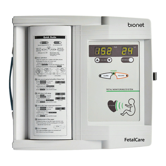
Fetal Monitor FC-700 Operating Manual ▣ Control Panel ① ② ③ ④ ⑤ ⑥ ⑦ ⑧ ⑨ ⑩ ① Heart rhythm symbol (Green : stable, Red : unstable). ② Heart rate of the fetus (bpm). ③ UC measurement value. ④ Volume up/down key. During the use of the Menu for setup, this key is used to change the setting value. -
Page 16: Explanation Of Sections Of Output Sheets
Fetal Monitor FC-700 Operating Manual 4) Explanation of Sections of Output Sheets ① Fetal heart rate per minute ② Fetal movement point that is indicated when Event Marker is pressed ③ Uterine contraction ④ Information on the recording condition ⑤…
-
Page 17: Cardiotocograph(Ctg) Analysis Output Paper Area
Fetal Monitor FC-700 Operating Manual 5) CardioTocoGraph(CTG) Analysis output paper area (Option) ① ② CTG Analysis results is printed out every 10 minute. (Intermediate Report) Start printing by pressing print button in order to analyze CTG and repress print button to stop printing process.
-
Page 18
Fetal Monitor FC-700 Operating Manual < Final Report > CTG REPORT (PERIOD : 0 — 15 MIN 0 SEC) AVERAGE BASELINE FHR(BPM) : 123 bpm NUMBER OF UC(FREQUENCY) : 5/ 20.0/h NUMBER OF ACC(FREQUENCY) : 0/ 0.0/h NUMBER OF DEC(FREQUENCY) : 5/ 20.0/h… -
Page 19: Product Installation
If you put the plug of power adaptor in the terminal of power adaptor of the main body of FC-700 and then switch it on, the equipment will work. If the power supply is normal, LED at the operation panel indicating Power On/Off will be turned on green.
-
Page 20: Software Version
▣ Setting of Recording Paper If you release the button to open the printer cover at the front of FC-700 to the right, it will open. Put recording paper with the recording part on the upper side adjusting the paper roll parallel to the print direction and then close the cover.
-
Page 21: Chapter 2. How To Use Fc-700
Chapter 2. How to Use FC-700 1) Basic operation ① Put the plug of FC-700 in an outlet and switch it on. ② Check setup values if they are set as wished. ③ Change the setup values, as you want.
-
Page 22: Fhr Measurement
Fetal Monitor FC-700 Operating Manual ▣ LAMP POWER: If it is switched on, the lamp will be turned on green. ALARM: If the alarm is on, the lamp will be turned on red. RECORD: During printing, the lamp will be turned on green.
-
Page 23
Fetal Monitor FC-700 Operating Manual Note When the Doppler Probe is put not on the back but on the breast part of a fetus, accurate ultrasonic waves can’t be caught from the fetal heart and the fetal heat beat can be frequently missed. -
Page 24: Uc Measurement
Fetal Monitor FC-700 Operating Manual 4) UC Measurement UC (Uterine Contraction) can be measured with an externally attached pressure sensor. If the UC Probe is put on the abdomen of a pregnant woman, it measures a relative pressure changing according to the uterine contraction and records uterine contraction.
-
Page 25: Measurement Of Fetal Movements
Fetal Monitor FC-700 Operating Manual 5) Measurement of Fetal Movements ▣ How to Use Event Marker Even Marker relys on the recognition of a pregnant woman to record a fetal movement point: when she feels a fetal movement, press a button on Event Marker. When Event Marker is pressed during recording, the fetal movement point is indicated with an arrow mark on recording paper with a signal of “Beep~”…
-
Page 26: Recording
Fetal Monitor FC-700 Operating Manual 6) Recording The recording functions include AUTO NST (Non-Stress Test) and monitoring. The AUTO NST function that records FHR, UC, and fetal movements for the period of established time and stops automatically is effective in the non-contraction test. The monitoring function enables a user to operate Start/Stop of recording.
-
Page 27: Fhr Alarm
Fetal Monitor FC-700 Operating Manual 7) FHR Alarm If FHR beyond the established upper or lowest limit of normal FHR exceeds the established delay time, an alarm is made. ▣ Order to Use the FHR Alarm Function ① Use the Volume Up/Down Key to set the value of “H” menu which means the upper limit of FHR and that of “L”…
-
Page 28: Equipment State Alarm
Fetal Monitor FC-700 Operating Manual 9) Equipment State Alarm The following circumstances raise a signal of “Ding-dong~” to ask a user to pay attention: ① The contacter of Doppler Probe in use is disconnected from the main body (Er1) ② Out of paper during recording (Er2) ③…
-
Page 29: Chapter 3. Setup Modes
Fetal Monitor FC-700 Operating Manual Chapter 3. Setup Modes The setup modes include those of alarm/time, recording, and factory. The factory setup is a part having great effect on the performance of the equipment if the set-up value is easily changed;…
-
Page 30
Fetal Monitor FC-700 Operating Manual ▣ How to Set the Date and Time ① To set the year, press the Alarm key for over two seconds and then the Reference key to indicate the following. It indicates that the current year is 2002. -
Page 31
Fetal Monitor FC-700 Operating Manual ④ To set the hour, press the Alarm key for over two seconds and then Reference key to indicate the following. It indicates “ 1 o’clock “ now. Use the Volume Up/Down Key to change the set-up hour. Press the Record Key to store the changed value and then return it to the basic state after a signal of “Ding-dong”. -
Page 32: Recording Setup
The output speed can be set at one of 1, 2, and 3 cm/min, and may be changed with the Volume Up/Down Key. ② Thermal paper for a facsimile can be used for FC-700 besides those supplied. To use those for a facsimile, press the Reference key for over two seconds and then for a short time to indicate the following.
-
Page 33
Fetal Monitor FC-700 Operating Manual ③ To control the contrast of graph, press the Reference key for over two seconds and then for a short time to indicate the following. Select 1 for a medium and 2 for the darker state, and use the Volume Up/Down Key to change it. -
Page 34
Fetal Monitor FC-700 Operating Manual ▣ How to set Cardio-Toco Graph(CTG) analysis function Press REFERENCE button for at least 2 seconds and repress REFERENCE button for a short amount of time in order to set automatic CTG diagnosis function. It should appear like the figure below. -
Page 35
Fetal Monitor FC-700 Operating Manual ▣ How to set Demo mode Press REFERENCE button for at least 2 seconds and repress REFERENCE button for a short amount of time in order to set Demo mode. It should appear like the figure below. Use the Volume Up/Down Key to change it. -
Page 36: Factory Setup
Fetal Monitor FC-700 Operating Manual 3) Factory Setup ▣ How to Set the FHR Alarm Delay To set the FHR alarm delay, switch it off (and then press the Volume Down key) and switch it on again pressing the Volume Up key. Then, the following appears which indicates that the alarm delay time (‘t’) is set at ten minutes.
-
Page 37: Chapter 4. Ctg Terminology
Fetal Monitor FC-700 Operating Manual Chapter 4. CTG Terminology 1) Baseline FHR Mean FHR rounded to increments of 5 bpm during a 10 minute segment excluding periodic or episodic changes, periods of marked variability and, segments of baseline that differ by >25bpm.
-
Page 38
Fetal Monitor FC-700 Operating Manual 4) EARLY DECELERATION Visually apparent gradual decrease(onset to nadir is ≥ 30 sec.) of FHR below baseline. Return to baseline associated with a uterine contraction. Nadir of deceleration occurs at the same time as the peak of the contraction. Generally, the onset, nadir, and recovery of the deceleration occur at the same time as the onset, peak and recovery of the contraction Rev.2.41… -
Page 39
Fetal Monitor FC-700 Operating Manual 5) Variable DECELERATION Visually apparent abrupt decrease ( onset to nadir is <30sec) in FHR below baseline. Decrease is ≥15 bpm. Duration is ≥ 2 min and < 10 min. Rev.2.41… -
Page 40: Chapter 5. Trouble Shooting
Chapter 5. Trouble shooting 1) Maintenance and Cleaning You can keep FC-700 clean in many different ways. Use the following recommendations to avoid the damage or stain to the machine. If the material (not approved material) that may cause damage to the product is used, the product is not guaranteed even within the period of guarantee is not expired.
-
Page 41: Regular Inspection
1) When DOP Probe does NOT work, it is connected to the other channel or exchange the DOP Probe. Also equal UC Probe. 2) If equipment does NOT work, you have to make a phone call service person of Bionet. For more information, see the Service Manual.
-
Page 42: Chapter 6. Specifications
Fetal Monitor FC-700 Operating Manual Chapter 6. Specifications Environmental Specifications Operating Temperature:15°C to 30°C (59°F to 86°F) Storage Temperature:- 10°C to 60°C (14°F to 140°F) Operating/Storage Humidity:20% to 95% RH, non-condensing Operating Altitude:70(700) to 106Kpa(1060mbar) Power Specifications Power Adaptor ;…
-
Page 43
Fetal Monitor FC-700 Operating Manual Recorder Recorder Method : Thermal Array Type Resolution: 8(vertical)/10(horizental) dot/mm Print Speed : 1, 2, 3 cm/min Paper Feeding Function Paper Grid : On/Off Print Contrast : 1, 2 Auto Print Period : 0, 10, 20, 30, 40, 50, 60… -
Page 44: Appendix A Maintenance, Care, And Service
Fetal Monitor FC-700 Operating Manual Appendix A Maintenance, Care, and Service Mechanical hazard Warning Ultrasound probes are highly sensitive medical instruments that can easily be damaged by improper handling. Use care when handling and protect from damage when not in use.
-
Page 45
Do not to touch signal input, signal output or other connectors, and the patient simultaneously. Refer servicing to qualified personnel of Bionet Co., Ltd. Probe acoustic output hazard Warning Ultrasound can produce harmful effects in tissue and potentially result in patient injury. -
Page 46: Appendix B Ultrasound Power
Fetal Monitor FC-700 Operating Manual Appendix B Ultrasound Power Use of Diagnostic Ultrasound The American Institute of Ultrasound in Medicine (AIUM) has published a document entitled «Medical Ultrasound Safety». This three part document covers Bioeffects and Biophysics, prudent Use and Implementing ALARA.
-
Page 47
Fetal Monitor FC-700 Operating Manual Maximum Probe Temperature (Degrees C) Probe Max Temperature With TMM In Air Mode Phantom 33.8 23.6 PWD Mode Lens temperature monitored for 30 min. Measurement uncertainty: +-0.5 degree C. Ambient temperature : 23.5 degree C Table Key Meaning IEC60601-2-37 / FDA&NEMA… -
Page 48
Fetal Monitor FC-700 Operating Manual Output Power / Time average acoustic power at the source Attenuated Output Power / Time average Pα W.3(Z) acoustic power derated to depth z Bounded Output Power / Power emitted from the central 1cm of aperture… -
Page 49
Fetal Monitor FC-700 Operating Manual Acoustic Output Tables MC65R1S – Pulsed Doppler Mode Index scan Non-scan Non-scan Aaprt<= 1 Aaprt > 1 Global Maximum : Index Value 0.014874 0.010567 0.166265 0.178513 Unit Associated pr.3 (MPa) 0.0148732 Acoustic (mW) 43.7 43.7 43.7… -
Page 50: Appendix C Abbreviation And Symbol
Fetal Monitor FC-700 Operating Manual Appendix C Abbreviation and Symbol Abbreviation and Symbol of manual or system operation is arranged in alphabetical order. Abbreviations alternating current Celsius cm, CM centimeter direct current electromagnetic compatibility electromagnetic interference Fahrenheit gram heart rate, hour…
-
Page 51
Fetal Monitor FC-700 Operating Manual kg, KG kilogram liter, left lbs, LBS pounds liquid crystal display light emitting diode M mean, minute meter MIN, min minute MM, mm millimeters MM/S millimeters per second MMHG, mmHg millimeters of mercury millivolt second… -
Page 52
Fetal Monitor FC-700 Operating Manual multiplier when used with a number (2X) Symbols & ° degree(s) > greater than < less than – minus number percent ± , +/- plus or minus Rev.2.41… -
Page 53: Appendix D Electromagnetic Emissions And Immunity — Manufacturer’s Declaration
Electromagnetic Emissions and Immunity Manufacturer’s declaration — electromagnetic emission The FC-700 system is intended for use in the electromagnetic environment specified below. The customer or the user of FC-700 system should assure that it is used in such an environment Emission test…
-
Page 54
Note: Uт is the a.c. mains voltage prior to application of the test level. The FC-700 system is intended for use in the electromagnetic environment specified below. The customer or the user of the FC-700 system should assure that it is used in such an environment Immunity test… -
Page 55
Fetal Monitor FC-700 Operating Manual Radiated RF 3 V/m 3 V/m Recommended separation IEC 61000-4-3 80.0 MHz to 2.5 80.0 MHz to 2.5 distance Where P is the maximum output power rating of the transmitter in watts (W) according to the… -
Page 56
Equipment and the FC-700 system. The FC-700 system is intended for use in an electromagnetic environment in which radiated RF disturbances are controlled. The user of the FC-700 system can help prevent electromagnetic interference by maintaining a minimum distance between portable… -
Page 57
Guidance and manufacturer’s declaration — electromagnetic immunity The FC-700 system is intended for use in the electromagnetic environment specified below. The customer or the user of the FC-700 system should assure that it is used in such an environment Immunity test… -
Page 58
Name : Tel : Sales Agency Manufacturer ※ Thank you for purchasing FC-700. ※ This product is manufactured and passed through strict quality control and inspection. ※ Compensation standard concerning repair, replacement, refund of the product complies with “Consumer’s protection law” noticed by Economic Planning Dept. -
Page 59
Fetal Monitor FC-700 Operating Manual International Sales & service Bionet Co., Ltd. : #1101 11F E&C Venture Dream Tower3, 38-21, Digital-Ro, 31-Gil, Guro-Gu, Seoul, 152-719, Republic of Korea Tel : +82-70-7585-6418 / Fax : +82-2-6499-7789 / e-mail: sales@ebionet.com Website: www.ebionet.com U.S.A sales &…
- Описание
- Характеристики
- Видео
- Прикрепленные файлы
Фетальный монитор Bionet FC 700 используется для диагностики состояния плода в акушерских стационарах и медицинских центрах. Это многофункциональное оборудование, которое отвечает всем современным требованиям и стандартам качества.
Корейская компания Bionet является одним из лидеров по производству медицинского оборудования в мире, а именно, фетальных мониторов. Также компания ведет активные разработки системы теле консультаций.
Принцип действия
Действие аппарата представляет собой внешнюю, неинвазивную методику определения активности сердца плода с помощью ультразвуковой диагностики. Устройство контролирует сократительную маточную активность, проводит токометрию, подсчитывает количество сокращений и движений плода.
Особенности
- Высокочувствительный фетальный монитор для одноплодной беременности;
- Возможность провести оценку функционального состояния и степень тяжести метаболической гипоксии плода;
- Производит автоматический расчет параметров и анализ антенатальной КТГ;
- Наличие принтера. Результаты исследований можно вывести на печать сразу на бумаге формата А4 или бумаге для факса;
- Стойкость датчиков к помехам;
- Удобные размеры и легкость перемещения;
- Компактные размеры, длительная работа от аккумулятора.
Страна изготовления
Южная Корея
Вид оборудования
Фетальные мониторы
Количество исследуемых плодов
1
Измеряемые параметры
- Маркер движения плода
- Маточное сокращение
- ЧСС плода
Печать
Распечатка любых данных с монитора.
Встроенный термопринтер
Встроенный КТГ анализ
Есть
Тип термобумаги
Рулон, возможность использования бумаги для факса с нанесением сетки
Частота ультразвука, МГц
1
Найти похожие

Фетальный монитор Bionet FC 700: инструкция

VER 1.0 May 15, 2002 BabyCare Service Manual
FC-700
SERVICE MANUAL

VER 1.0 May 15, 2002 FC-700 Service Manual
2
BioNet CO., LTD.

VER 1.0 May 15, 2002 FC-700 Service Manual
3
Terms of Warranty
— This product is manufactured and passed through strict quality control
and inspection.
— Compensation standard concerning repair, replacement, refund of the
product complies with “Consumer’s protection law” noticed by Economic
Planning Dept.
— FC-700 is warranted by Bionet Co.,Ltd to be free from defects in material
and workmanship for two years from date of purchase.
— Warranty repair or replacement will be made by Bionet Service Center at
no charge during warranty period if properly used under normal condition
in accordance with the instructions for use.
— In the event of a malfunction or failure during warranty period, customer
should inform Bionet Co.,Ltd of the model name, serial number, date of
purchase and explanation of failure about the defective equipment.

VER 1.0 May 15, 2002 FC-700 Service Manual
4
Definition of Warning, Caution, Note For a special emphasis on agreement, terms are defined as listed below
in operation manual. Users should operate the equipment according to
all the Warning and Caution instructions.
Manufacturer or Sales agency takes no responsibility for any kind of
damage or breakdown that is caused by misuse and failure to maintain
the equipment..
Warning
Be informed that it may cause serious injury or death to the
patient, property damage, material losses against the
“Warning” sign.
Caution
Be informed that it may cause no harm in life but lead to
injury against the “Caution” sign.

VER 1.0 May 15, 2002 FC-700 Service Manual
5
Note
Be informed that “Note” sign is used for notifying some
important contents relating to installations, use,
maintenance for users, but not dangerous.

VER 1.0 May 15, 2002 FC-700 Service Manual
6
General Precaution on Environment
Do not keep or operate the equipment in the environment listed below.
Avoid placing in an area
exposed to moist. Do not
touch the equipment with
wet hand .
Avoid exposure to direct
sunlight
Avoid placing in an area
where there is a high
variation of temperature.
Operating temperature
ranges from 10 C to
40 C. Operating humidity
ranges from 30% to 85%.
Avoid in the vicinity of
Electric heater
Avoid placing in an area
where there is an
excessive humidity rise or
ventilation problem.
Avoid placing in an
area where there is an
excessive shock or
vibration.
Avoid placing in an area
where chemicals are
stored or where there is in
danger of gas leakage.
Avoid dust and
especially metal
material into the
equipment
Do not disjoint or
disassemble the equipment.
Bionet Co.Ltd takes no
responsibility of it
Power off when the
equipment is not
fully installed.
Otherwise,
equipment could be
damaged.

VER 1.0 May 15, 2002 FC-700 Service Manual
7
General Precaution on Electric Safety
Check the items listed below before operating the equipment.
— Be sure that power supply line is appropriate to use.
(Power Adaptor Input : 100 — 240V AC, Power Adaptor Output : 18V, 2.5A).
— Be sure that the entire connection cable of the system is properly and firmly
fixed.
Note : The equipment should not be placed in the vicinity of electric
generator, X-ray, broadcasting apparatus to eliminate the electric noise
during operation. Otherwise, it may cause incorrect result.
Self-power line is important for FC-700. To use same power source with
other electric instruments may cause incorrect result.
Note : FC-700 is classified as listed below ;
— This equipment conforms to Class I, Type-BF.
— Do not use the equipment in the vicinity of flammable anesthetics
and solvents.
— The equipment conforms to Class I according to IEC/EN 60601-1
(Safety of Electric Medical Equipment)
— This equipment conforms to Level B according to IEC/EN 60601-
1-2 (Electromagnetic Compatibility Requirements)
Note : Accessory equipment connected to the analog and digital
interfaces must be certified according to the respective IEC standards
( e.g. IEC 950 for data processing equipment and IEC 601-1 for medical
equipment ). Furthermore all configuration shall comply with the system
standard EN 60601-1-1:1993.
If in doubt, consult the technical service department or your local
representative.

VER 1.0 May 15, 2002 FC-700 Service Manual
8
Safety Symbols
■ The International Electrotechnical Commission (IEC) has established
a set of symbols for medical electronic equipment which classify a
connection or warn of any potential hazards. The classifications and
symbols are shown below.
Save these instructions.
Symbols contents
Isolated patient connection. (IEC 601-1-Type BF)
Device part switched off.
Device part switched on.
Conductor provides a connection between
equipment and the potential equalization busbar of
the electrical installation
External Signal IN/OUT Port
.

VER 1.0 May 15, 2002 FC-700 Service Manual
9
========================================================
CONTENTS
========================================================
Terms of Warranty
How to reach us
Definition of Warning, Caution, Note
General Precaution on Environment
General Precaution on Electric Safety
1. Product Overview
1) Product Description
2) Product Features
3) Product Configuration
4) Product Installation
2. Function Block Analysis
1) Overall Block Diagram
2) Doppler Signal Processing Block
3) UC Signal Processing Block
4) Sound Block
5) Main CPU Block
3. Troubleshooting
1) Power on failure
2) 7-LED is off although the power is on
3) Sound problem
4) When the printer is not working properly
5) When the keyboard is not working
6) When the serial interface is not working
4. Technical Specification
5. Service Part List
6. Calibration

VER 1.0 May 15, 2002 FC-700 Service Manual
10
7. PCB Board Diagram
8. Assembly Drawings
1. Product Overview
1) Product Description
FC-700 is the fetal monitor that measures the fetal heart rate and uterine
contraction. FC-700 irradiates ultrasound wave to the abdomen of a pregnant woman,
and detects the Doppler frequency signal reflected from the heart of the fetus. FC-700
analyzes this signal and displays the heart rate by LED. Also, FC-700 provides the
sound from the heart of fetus.
FC-700 measures the uterine contraction of a pregnant woman by pressure sensors
and displays the numerical values.
And FC-700 records the heart rate of the fetus, fetal movement and the values of
uterine contraction.
2) Product Features
— FC-700 records the heart rate of the fetus, fetal movement and the uterine
contraction of a pregnant woman, and basic information of the equipment with wide
A4 Size paper.
— FC-700 can use general fax paper as well as thermal paper for fetal monitor.
— FC-700 has automatic NST function which records FHR, UC and fetal movement
only for the established time.
3) Product Configuration
FC-700 system consists of the following. Unpack the package and check the
followings are included. Also, be sure to check any damage to the main body and
accessories.
① FC-700 main body
② Ultrasound Doppler Probe (1 EA)
③ UC Probe (1EA)

VER 1.0 May 15, 2002 FC-700 Service Manual
11
④ Event Mark Jack (1EA)
⑤ Print Paper (1EA)
⑥ Power Adaptor (1EA)
⑦ Power Cord (1EA)
⑧ Ultrasound Gel (1EA)
⑨ Probe Belt (2EA)
⑩ Operation Manual (1EA)
⑪ Stand (1EA)
⑫ Basket (1EA)
4) Main Body configuration
▣ Top view

VER 1.0 May 15, 2002 FC-700 Service Manual
12
① ② ③ ④ ⑤
① Hand Grip
② Printer door
③ Printer door release button
④ Display LED
① ②

VER 1.0 May 15, 2002 FC-700 Service Manual
13
⑤ Control panel

VER 1.0 May 15, 2002 FC-700 Service Manual
14
▣ Front view
①
① Printer door release button
▣ Rear view
① ② ③
④

VER 1.0 May 15, 2002 FC-700 Service Manual
15
① Power adaptor connection port
② Power on/off switch
③ RS-232C serial port
④ Mark Jack connection port
① ②

VER 1.0 May 15, 2002 FC-700 Service Manual
16
▣ Left side view
① Hand Grip
▣ Right side view
① Doppler, UC Probe connection port
①
①

VER 1.0 May 15, 2002 FC-700 Service Manual
17
Warning
To avoid an expected electric shock, do not open the equipment cover or
disassemble the equipment. Refer servicing to qualified personnel of
Bionet Co., Ltd.

VER 1.0 May 15, 2002 FC-700 Service Manual
18
▣ Control Panel
① ② ③
④ ⑤ ⑥ ⑦ ⑧ ⑨ ⑩
① Heart rhythm symbol (Green : stable, Red : unstable).
② Heart rate of the fetus (bpm).
③ UC measurement value.
④ Volume up/down key. During the use of the Menu for setup, this key is
used to change the setting value.
⑤ LED of the alarm on/off
⑥ Alarm on/off key. During the use of the Menu for setup, this key is used
to set the function of the time and date.
⑦ LED of the power on/off
⑧ Print on/off Key. When setup mode, store the setting value. When out of

VER 1.0 May 15, 2002 FC-700 Service Manual
19
print, paper feeding function.
⑨ LED of the print on/off
⑩ Key setting UC value as reference value(10). When setup mode,
printing related functions setup.
4) Product Installation
▣ Attention in Installation
Pay attention to the following in installing FC-700:
① Use it at the temperature between 10 and 40 degrees centigrade and at
the humidity between 30 and 85 percent.
② Check plug-in and treat the Probe Cable carefully.
③ Don’t put several plugs in an outlet.
④ Install the main body at the flat place.
⑤ Avoid using a plug making a noise in plug-in.
⑥ All the setup will be recorded at the interior memory even when it is
switched off and then on.
⑦ Be careful, as it is easy to break by the shock.
⑧ Install it away from dust or inflammable things in consideration of the
temperature and humidity.
▣ Power Supply
Use free voltage of AC between 100 and 250V. If a plug is put in an outlet, the
“POWER” LED at operation panel will be turned on green. Within the equipment
is a battery to change the date and time even when it is switched off. Use a
Type CR2032 3V Lithium Battery.
☞ Note!
Don’t throw away batteries carelessly to protect environment, but
ask the hospital for the designated places to dump batteries
according to proper procedure.

VER 1.0 May 15, 2002 FC-700 Service Manual
20
▣ Plug-in
Put the plug in an outlet of 110V or 220V and connect one side of power cable
to the power adaptor. If you put the plug of power adaptor in the terminal of
power adaptor of the main body of FC-700 and then switch it on, the equipment
will work.
If the power supply is normal, LED at the operation panel indicating Power
On/Off will be turned on green.
▣ Connection of the Probe Cable
Connect the Probe Cable to the Probe Cable terminal at the right side of the
main body.
Connect the Doppler Probe to the “DOP” terminal and the UC Probe to the “UC”
terminal.
Connect Mark Jack to the “MARK” terminal at the backside of the main body.
▣ Setting of Recording Paper
If you release the button to open the printer cover at the front of FC-700 to the
right, it will open. Put recording paper with the recording part on the upper side
adjusting the paper roll parallel to the print direction and then close the cover.

VER 1.0 May 15, 2002 FC-700 Service Manual
21
2. Functional Block Analysis
1) Overall Block Diagram
Overall Block Diagram is mainly divided into an analogue part and digital part.
The analogue part consists of the Doppler & UC probe analogue part where receives

VER 1.0 May 15, 2002 FC-700 Service Manual
22
bio-signals (Doppler sound & UC) and an analogue-to-digital converter which charges
the analogue signals into the digital signals. Also it processes the out of the Doppler &
alarm sound.
The digital part consists of those parts below.
1. Analogue to digital converting : the signal of FHR & UC, Fetal movement
2. Display : the values of FHR & UC
3. Alarm sound generation
4. Volume control
5. Key scan
6. Print date generation
7. Interface of PC (RS232)
2) Doppler Signal Processing Block
Doppler Signal Processing Block consists of those parts below.
1. Control logic : generate the Tx wave using the 16MHz clock
2. Tx : Amplify the signal where receives control logic and then transport the
signal to Doppler probe.

VER 1.0 May 15, 2002 FC-700 Service Manual
23
3. AMP : Amplify the signal where receives Doppler probe
4. Demodulation : Demodulate the signal from the AMP
5. LPF & HPF : Filtering the signal
6. Full wave rectify
3) UC Signal Processing Block
UC Signal Processing Block consists of those parts below.
1. Amplify UC signal which is measured by using the Strain gage.
2. Convert the analogue signal to the digital signal.
4) Sound Block

VER 1.0 May 15, 2002 FC-700 Service Manual
24
Sound Block consists of those parts below.
1. Control the volume level of the Doppler signal
2. After receiving the Doppler signal & Alarm signal, make the output of sound by
using the Audio Amp.
5) Main CPU Block

VER 1.0 May 15, 2002 FC-700 Service Manual
25
Main CPU Block consists of those parts below.
1. Calculate the FHR & UC values after processing the signal of the Doppler & UC
input and then output the signal in the 7-LED display
2. Check the status of the connection between Doppler & UC and main body, and
then send the message of the status
3. Transport the Mark signal to print and Central monitoring system
4. Control the sound volume.
5. Generate the control signal and date of the printer & motor by using the printer
engine, and then check the paper empty
6. Apply and save the status of Print & Alarm, Time setup after receiving the key
input.
7. Generate the check-signal of Watch Dog.

VER 1.0 May 15, 2002 FC-700 Service Manual
26
3. Troubleshooting

VER 1.0 May 15, 2002 FC-700 Service Manual
27
No
Yes
A
B

VER 1.0 May 15, 2002 FC-700 Service Manual
28

VER 1.0 May 15, 2002 FC-700 Service Manual
29
No
No
Yes
B
A
B
No
No
No
No
Yes
Yes
Yes
Yes
Yes
No
No
Yes
Yes
A
A
A
A
A

VER 1.0 May 15, 2002 FC-700 Service Manual
30

VER 1.0 May 15, 2002 FC-700 Service Manual
31
Yes
No
NoNo
Yes
B
A
B
A
Yes A
No
A
Yes

VER 1.0 May 15, 2002 FC-700 Service Manual
32
4. Technical Specification
Environmental Specifications
Temperature Range
Operating : 10 to 40℃
Storage : -10 to 60℃
Relative Humidity Range
Operating : 30 ~ 85%
Storage : 20 ~ 95%
Atmospheric Pressure Range
Operating : 70 ~ 106kPa
Storage : 70 ~ 106kPa
Power Specifications
Power Adaptor Input : 100 — 250VAC, 50/60Hz, about 80VA
Power Adaptor Output : 16V, 2.8A
Power Fail Protection
Battery : CR 2032 3V Lithium battery
Performance Specifications
FHR Measurement
Input signal : Ultrasound Pulsed Doppler
Ultrasound Frequency : 1.0 MHz
Ultrasound Power : <10mW/cm2
FHR Detection Method: Auto Correlation
Measurement Range : 50 ~ 240 beats per minutes(BPM)
FHR Accuracy : ±1 bpm over normal FHR range
UC Measurement
Input Source : External Transducer with strain gauge
Frequency Response : DC ~ 0.5 Hz

VER 1.0 May 15, 2002 FC-700 Service Manual
33
Reference(Zero) Control : One touch switch
Measurement Range : 0 ~ 99 units
Fetal Movement Measurement
Detection Source : Ultrasound Pulsed Doppler
Recording Method:
① Spike-like waveform on UC channel denotes relative intensity and duration
of Fetal Movement.
② Dot marks between FHR and UC channels when FM intensity exceeds
selected threshold.
Recorder
Recorder Method : Thermal Array Type
Resolution: 8(vertical)/10(horizontal) dot/mm
Print Speed : 1, 2, 3 cm/min
Paper Feeding Function
Paper Grid : On/Off
Print Contrast : 1, 2
Auto Print Period : 0, 10, 20, 30, 40, 50, 60
Fetal movement: On/Off
Display
Five 7-Segment LED
2 Channels (FHR, UC)
Indicators
Heart Rhythm (Green : Stable, Red : Unstable)
Alarm On/Off State
Print On/Off State
AC Power (Green LED)
Sound
Doppler Sound with Volume Control (8 steps)
Alarms Sound :
Information Sound : Doppler Probe off, Paper off, Watch Dog, Set-up Data

VER 1.0 May 15, 2002 FC-700 Service Manual
34
Storage
NST End.
Set-up
Alarm Upper/Lower Limit Value
Alarm check delay time
Print Speed
Paper Grid
Print Contrast
Auto Print Period(NST time)
Time / Date
Fetal Movement On/OFF
Fetal Movement Detection Threshold
Function
Event Mark Function
External Link
RS232C : Program Down Load, Central (Option)

VER 1.0 May 15, 2002 FC-700 Service Manual
35
5. Service Part List
Item Quantity Reference Part
1 1 BT1 3V 2032 Lithium Ion Battery
2 3 C1, C141, C142 330pF
3 86
C2,C4,C5,C6,C7,C8,C9,C12,
C16,C18,C19,C20,C21,C24,
C27,C29,C32,C33,C34,C35,
C36,C37,C38,C39,C40,C42,
C43,C44,C45,C47,C48,C50,
C52,C54,C55,C56,C57,C58,
C59,C62,C63,C64,C65,C68,
C70,C71,C72,C75,C76,C81,
C83,C84,C86,C87,C88,C91,
C97,C99,C109,C110,C112,
C113,C114,C115,C116,C117,
C118,C119,C120,C121,C122,
C123,C124,C125,C126,C127,
C129,C133,C134,C135,C140,
C144,C146,C149,C150,C151
100nF
4 7 C3,C41,C66,C67,C78,C82,C85 T10uF
5 20
C10,C13,C17,C25,C28,C49,
C61,C90,C92,C93,C94,C95,
C96,C103,C104,C105,C106,
C107,C108,C111
1nF
6 1 C11 47nF
7 12 C14,C15,C30,C51,C53,C77,C79,
C80,C98,C100,C101,C102 10nF

VER 1.0 May 15, 2002 FC-700 Service Manual
36
8 2 C154,C22 4.7nF
9 1 C23 510pF
10 2 C26,C152 22nF
11 1 C31 3.3nF
12 1 C46 820pF
13 1 C60 15nF
14 3 C69,C147,C148 220nF
15 2 C73,C74 22pF
16 1 C89 1uF
17 2 C128,C132 100uF
18 1 C130 T1uF
19 3 C131,C138,C145 470uF
20 1 C136 1000uF
21 1 C137 22uF
22 1 C139 2.2uF
23 1 C143 470nF
24 1 C153 33nF
25 7 D1,D2,D3,D4,D5,D6,D7 1N4148
26 2 D8,D9 1N5158
27 2 G2,G3 Test Point
28 5 H1,H2,H3,H4,H5 MH
29 1 J1 HEADER 7 X 2
30 2 J2,J3 LMB0509-6P
31 1 J4 5267-3
32 1 J5 8283-14
33 1 J6 HIF3F-26PA-2.54DSA
34 1 J7 5267-6
35 1 J8 5267-4
36 2 J9,J12 5267-2
37 1 J10 HTJ-020-04
38 1 J11 HTJ-035-10
39 2 L1,L2 27uH
40 3 L3,L4,L5 220uH

VER 1.0 May 15, 2002 FC-700 Service Manual
37
41 1 P1 D-SUB 9 pin
42 1 Q1 MMBT3906
43 6 Q2,Q3,Q4,Q5,Q6,Q7 MMBT3904
44 5 Q8,Q9,Q10,Q11,Q12 DTA123
45 11 R1,R2,R8,R14,R17,R20,R23,R37
,R86,R139,R153 1K
46 9 R3,R111,R112,R113,R114,R115,
R116,R117,R119 100
47 14 R4,R5,R11,R18,R19,R24,R25,
R32,R33,R45,R61,R68,R79,R142 20K
48 30
R6,R7,R10,R12,R13,R15,R28,R29,
R30,R31,R34,R42,R43,R44,R46,R47
,R55,R57,R62,R67,R70,R71,R72,
R74,R76,R77,R78,R88,R90,R141
10K
49 3 R9,R16,R54 2M
50 1 R21 15K
51 1 R22 470
52 3 R26,R50,R69 68K
53 2 R27,R89 51K
54 9 R35,R65,R91,R92,R98,R129,R130,
R131,R132 100K
55 6 R36,R49,R51,R87,R135,R136 20
56 7 R38,R48,R56,R64,R96,R97,R99 200K
57 1 R39 33K
58 6 R40,R58,R63,R75,R150,R151 2K
59 2 R41,R73 6.8K
60 5 R52,R66,R83,R85,R152 3.3K
61 2 R53,R143 150K
62 1 R59 10K 1%
63 1 R60 430K
64 1 R80 20K
65 1 R81 150K 1%
66 2 R82,R84 30K 1%

VER 1.0 May 15, 2002 FC-700 Service Manual
38
67 14
R93,R95,R107,R118,R120,R121,
R122,R123,R124,R125,R126,
R127,R128,R133
4.7K
68 1 R94 75K
69 5 R100,R101,R102,R103,R104 10
70 5 R105,R106,R108,R109,R110 330
71 1 R134 1
72 1 R137 33K 1%
73 1 R138 2K 1%
74 1 R140 220
75 2 R144,R145 120K
76 1 R146 56K
77 1 R147 270K
78 1 R148 560K
79 1 R149 180K
80 4 R154,R155,R156,R157 680
81 1 U1 DG212
82 2 U2,U5 74HC08
83 2 U3,U4 74HC393
84 2 U6,U20 74HC04
85 1 U7 SST39VF040(PLCC)
86 5 U8,U9,U14,U15,U33 TL064
87 1 U10 CD4051B
88 1 U11 K4S641632D
89 1 U12 S3C44B0X
90 1 U13 OSC 16MHz(3.3V)
91 1 U16 LM1117MPX-2.5
92 1 U17 LM78L05
93 1 U18 LM1117MPX-3.3

VER 1.0 May 15, 2002 FC-700 Service Manual
39
94 2 U19,U29 LM7812
95 1 U21 MM1075
96 5 U22,U23,U24,U25,U26 74HC245
97 1 U27 MAX232CSE
98 1 U28 ULN2064
99 1 U30 TDA2030
100 1 U31 LM2576S-5.0
101 1 U32 PQ2CF1
102 1 X1 32.768KHz
6. Calibration
1) UC calibration
1. Turn on the power with pushing the Reference key. At this time, the
display of FHR shows the value of UC and the display of UC shows UC.
2. Open the upper cover of UC probe.
3. Turn the variable resistance toward the counterclockwise until the value of
UC shows around 300.
4. Turn the variable resistance toward the clockwise until the value of UC
shows 550 ~ 600.

VER 1.0 May 15, 2002 FC-700 Service Manual
40
5. Close the upper cover of UC probe.

VER 1.0 May 15, 2002 FC-700 Service Manual
41
7. PCB Board Diagram

VER 1.0 May 15, 2002 FC-700 Service Manual
42

VER 1.0 May 15, 2002 FC-700 Service Manual
43
8. Assembly Drawings
- Портативный, настольный
- Для одноплодной беременности
- Дисплей: монохромный светодиодный
- 5 функциональных клавиш
- 2 канала (пульс плода, маточное сокращение)
- Водонепроницаемые датчик ЧСС плода и тензодатчик
- 8 уровней громкости сердцебиения плода
- Регистрационное удостоверение
Арт. 6720
Монитор фетальный Bionet FC 700
- Описание
- Характеристики
- Комплектация
- Данные для транспортировки
- Документация
- Фетальный монитор Bionet FC 700 предназначен для регистрации состояния плода и активности матки в антенатальном и интранатальном периоде при одноплодной беременности
- Является незаменимым оборудованием для женских консультаций, перинатальных центров и роддомов
- Позволяет оценивать как функциональное состояние, так и степень тяжести гипоксии плода
- Производит автоматический расчет параметров и анализ антенатальной КТГ
- На дисплее отображает частоту сердечных сокращений плода и маточные сокращения
- Имеет водонепроницаемые датчики: высокочувствительный 7 кристальный датчик регистрации ЧСС плода и тензодатчик
- Особенности:
— монохромный светодиодный 7 сегментный дисплей
— ультразвуковой датчик для регистрации ЧСС плода состоит из 7 кристаллов, обеспечивает большое поле обзора, что повышает диагностические возможности
— ультразвуковая частота 1 МГц
— точное отображение сердечного ритма (FHR) и активности матки (UC)
— автоматическое обнаружение движения плода
— регулировка громкости сердцебиений плода (8 уровней)
— легко читаемый тренд данных (FHR, UC)
— нестрессовый тест 10, 20 ,30, 40, 50, 60 мин
— встроенный принтер, скорость печати — 1,2,3 см/мин
— диаграммная бумага формата A4
— возможность использования бумаги для факса
— простота в использовании
— сигналы тревог (при тахикардии и брадикардии)
— чувствительный токографический датчик
— автоматическая расшифровка КТГ
— сенсорные кнопки управления
Перед применением необходимо ознакомиться с инструкцией по применению (паспортом изделия) или получить консультацию специалиста
Тип
портативный, настольный
Дисплей
монохромный светодиодный 7 сегментный
Отображение
ЧСС плода, сила маточных сокращений, качество сигнала
Печать
встроенный термопринтер
Тип термобумаги
рулон, возможность использования бумаги для факса с нанесением сетки
Программное обеспечение
нет
Проводной централизованный мониторинг
нет
Беспроводной централизованный мониторинг
есть
Встроенный КТГ анализ
есть
Кросс-канальная верификация
есть
Частота ультразвука, МГц
1
Централизованный мониторинг
есть
Держатель для датчиков
нет
Электропитание от сети переменного тока, В/Гц
100–240/50–60
Гарантия производителя, мес.
12
Монитор фетальный Bionet FC 700
Перед применением необходимо ознакомиться с инструкцией по применению (паспортом изделия) или получить консультацию специалиста
- Монитор фетальный FС 700 Fetal (блок аппарата базовый) — 1 шт.
- Датчик TOCO для фетальных мониторов FС 700 — 1 шт.
- Датчик US для фетальных мониторов FС 700 — 1 шт.
- Маркеры событий (Event marker) — 1 шт.
- Бумага для устройства регистрации данных — 2 шт.
- Блок питания — 1 шт.
- Гель для ультразвуковых исследований — 1 шт.
- Пояса для датчиков — 2 шт.
- Руководство по эксплуатации
- Паспорт
Габариты в упаковке, м
0,4х0,4х0,21
Количество изделий в упаковке
1
Упаковка
3-х слойный гофрокартон
Дополнительная упаковка
требуется
Фетальный монитор FC 700 — высокочувствительный, для дородовой диагностики состояния плода одноплодной беременности.
Фетальный монитор FC 700 легок в установке и в использовании. Ультразвуковой датчик частотой 1 МГц позволяет получит качественный сигнал даже в сложных для диагностики случаях.
Излучающая часть ультразвукового датчика для регистрации ЧСС плода состоит из 7 кристаллов, обеспечивающая большое поле обзора и повышая диагностические возможности прибора. Чувствительный токо-датчик. Автоматическая/ ручная регистрация движения плода.
Функции тревоги — тахикардия, брадикардия плода (FHR), сенсорные кнопки управления.
Сохранение данных.
Легко читаемые тренды ЧСС плода (FHR) и маточных сокращений (UC) можно распечатать на диаграммной бумаге формата А4 (встроенный принтер), скорость печати — 1,2,3 см/ мин.
Возможность использования бумаги для факса.
Возможна поставка подставки для прибора, что увеличивает удобства использования.
Особенности:
- Ультразвуковая частота 1,0 МГц
- Точный FHR и UC тренд
- Автоматическое обнаружение движения эмбриона (Automatic Fetal Movement)
- Легко читаемый тренд данных (FHR,UC) фетального монитора
- Диаграммная бумага формата A4
- Детальное аннотирование записей
- Лёгкость монитора фетального в установке и использовании
- Громкость, информация по UC, тревога, кнопки записи
- Функция тревоги фетального монитора FHR высокий/низкий
Комплектация:
- Основной блок фетального монитора Fc 700
- Ультразвуковой доплеровский датчик (1 шт.)
- ТОСО-датчик (1 шт.)
- Маркер для метки события (1 шт.)
- Бумага для печати (2 шт.)
- Адаптер электропитания (1 шт.)
- Шнур электропитания (1 шт.)
- Гель для ультразвука (1 шт.)
- Ремни для датчика (2 шт.)