
Мультимедийное руководство по техническому обслуживанию и ремонту Fiat 500 с 2007 года выпуска, многоязычный интерфейс (русского нет).
- Автор: —
- Издательство: —
- Год издания: —
- Страниц: —
- Формат: ISO
- Размер: 130,7 Mb
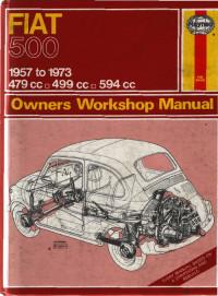
Руководство на английском языке по техническому обслуживанию и ремонту Fiat 500 1957-1973 годов выпуска.
- Автор: J.H. Haynes, J.C. Larminie
- Издательство: Haynes Publishing
- Год издания: 1992
- Страниц: 161
- Формат: PDF
- Размер: 13,0 Mb
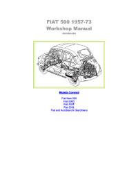
Руководство на английском языке по техническому обслуживанию и ремонту Fiat 500 1957-1973 годов выпуска.
- Автор: —
- Издательство: —
- Год издания: —
- Страниц: 128
- Формат: PDF
- Размер: 6,7 Mb

Руководство по эксплуатации и техническому обслуживанию автомобиля Fiat 500 с 2007 года выпуска.
- Автор: —
- Издательство: Automachanic
- Год издания: —
- Страниц: 227
- Формат: PDF
- Размер: —

Подборка руководств по эксплуатации Fiat 500 2007-2014 годов выпуска.
- Автор: —
- Издательство: Fiat Auto
- Год издания: 2007/2012/2014
- Страниц: 228/246/283
- Формат: PDF
- Размер: 74,3 Mb

Ищу мануал!

Может, кто подскажет, где можно скачать на Русском.
Комментарии
26
Войдите или зарегистрируйтесь, чтобы писать комментарии, задавать вопросы и участвовать в обсуждении.

На ютуб есть видео, как коннектиться с «блю энд ми». Я свою сконнектил. Правда музыка только по AUX.

У меня есть на английском. Именно мануал в полном смысле этого слова. Покупал на али вроде. На фиат 500 и панду 2004-2012 г.в. страниц наверное 100 с черно-белыми фотографиями. Издательство Haynes/
Спасибо. Нашел на Русском.166 страниц. Ссылку выложил. На английском у меня книжка шла с машинкой.

В России продают фиаты без мануала на Русском?
Эти мануалы только для дилера. Они не должны быть доступны обычным людям
Это странно! Для Альфы есть мануал на Русском.
MaxxxPower
Эти мануалы только для дилера. Они не должны быть доступны обычным людям
Разве, чтобы сконектить мобилу с blue&me, нужно обращаться к дилеру?
Так это не мануал, это руководство пользователя вам нужно
user’s manual и есть руководство пользователя
Я не говорил про users. Мануал а моем понятии руководство по ремонту
MaxxxPower
Так это не мануал, это руководство пользователя вам нужно
Может ты знаешь где скачать руководство пользователя?

MaxxxPower
Эти мануалы только для дилера. Они не должны быть доступны обычным людям
Дилеры тоже пользуются мануалом на английском
Все комментарии
- Руководства по ремонту — Fiat 500 (2008+) — Правила управления механической коробкой передач с электронным управлением Dualogic
- 231 просмотров
- 0
Расход топлива, рассчитанный в соответствии с директивой 999/100/EC (литров x 100 км) Городской цикл Вне города Комбинированный цикл 1.2 8V 6,2 4,3 5,0 1.4 16V 7,3 5,2 6,0 Значения расхода топлива соответствуют режиму AUTO-ECO для версий с двигателем 1.2 8V […]
Читать
- Руководства по ремонту — Fiat 500 (2008+) — Правила управления механической коробкой передач с электронным управлением Dualogic
- 116 просмотров
- 0
Образование CO2 (расчет в соответствии с директивой 1999/100/CE, г x 100 км) Суммарный объем образования CO2 для автомобилей с двигателем 1.2 8V составляет 118 (гx100 км). Суммарный объем образования CO2 для автомобилей с двигателем 1.4 16V составляет 140 (гx100 км).
Читать
- Руководства по ремонту — Fiat 500 (2008+) — Правила управления механической коробкой передач с электронным управлением Dualogic
- 389 просмотров
- 0
1.2 8V — 1.4 16V Рабочие жидкости, рекомендованные к применению Гидросистема трансмиссии Dualogic 0,70 литров 0,59 кг Специальная жидкость TUTELA CAR CS SPEED с добавлением «ATF DEXRON III»
Читать
- Руководства по ремонту — Fiat 500 (2008+) — Ваш автомобиль — Аудиосистема
- 171 просмотров
- 0
Технические характеристики — два 165-миллиметровых среднечастотных громкоговорителя мощностью 40 Вт каждый в передних дверях; — два 38-миллиметровых высокочастотных громкоговорителя мощностью 30 Вт каждый на задней стороне панели; — антенна на крыше автомобиля; — радиоприемник с CD MP3-проигрывателем. При установке Hi-Fi […]
Читать
- Руководства по ремонту — Fiat 500 (2008+) — Правила управления механической коробкой передач с электронным управлением Dualogic
- 89 просмотров
- 0
Масса (кг) 1.2 8V 1.4 16V Собственная масса (включая рабочие жидкости, запасное колесо, инструменты и принадлежности). 900 940 Полезная нагрузка (*), включая вес водителя 440 440 Максимально допустимая нагрузка (**) — на переднюю ось, — на заднюю ось, — полная […]
Читать
- Руководства по ремонту — Fiat 500 (2008+) — Правила управления механической коробкой передач с электронным управлением Dualogic
- 174 просмотров
- 0
Коробка передач Пять передних передач и одна передача заднего хода, оснащена электрогидравлической системой с электронным управлением Сцепление Привод электрогидравлический, с электронным управлением Тип привода автомобиля Передний
Читать
- Руководства по ремонту — Fiat 500 (2008+) — Ваш автомобиль — Аудиосистема
- 188 просмотров
- 0
Общие функции оборудования Радиоприемник: — Прием радиостанций с использованием технологии фазовой подстройки частоты (Phase Locked Loop, PLL) в частотных диапазонах FM/AM/MW/LW; — Радиоприемник поддерживает следующие функции: RDS, TA, TP, EON, REG; — AF: поиск альтернативных радиочастот в режиме RDS; — […]
Читать
- Руководства по ремонту — Fiat 500 (2008+) — Правила управления механической коробкой передач с электронным управлением Dualogic
- 86 просмотров
- 0
Наибольшая фактическая скорость автомобиля с двигателем версии 1.2 8V составляет 160 км/ч. Наибольшая фактическая скорость автомобиля с двигателем версии 1.4 16V составляет 182 км/ч.
Читать
- Руководства по ремонту — Fiat 500 (2008+) — Ваш автомобиль — Аудиосистема
- 71 просмотров
- 0
Помните о том, что загрязнения и царапины на диске могут стать причиной пропусков фрагментов записей и снижения качества воспроизведения. Вот несколько советов, соблюдение которых позволит достичь наилучшего качества звучания: — используйте компакт-диски только имеющие маркировку: — осторожно удаляйте с диска […]
Читать
- Руководства по ремонту — Fiat 500 (2008+) — Правила управления механической коробкой передач с электронным управлением Dualogic
- 132 просмотров
- 0
Версия двигателя Код типа двигателя Код исполнения кузова 1.2 8V 169A4000 312AXA11 1.4 16V 169A3000 312AXC11
Читать
-
Contents
-
Table of Contents
-
Bookmarks
Quick Links
FIAT 500 1957-73
Workshop Manual
Autobooks
Models Covered
Fiat New 500
Fiat 500D
Fiat 500F
Fiat 500L
Fiat and Autobianchi Giardiniera
Related Manuals for Fiat 500L
Summary of Contents for Fiat 500L
-
Page 1
FIAT 500 1957-73 Workshop Manual Autobooks Models Covered Fiat New 500 Fiat 500D Fiat 500F Fiat 500L Fiat and Autobianchi Giardiniera… -
Page 2: The Engine
CHAPTER 1 THE ENGINE 1 :1 Description 1 :12 Flywheel and starter ring gear 1 :2 Engine removal (sedan—all versions) 1 :13 The oil pump 1 :3 Engine removal (station wagon) 1 :14 Lubrication, oil filter, relief valve 1 :4 Engine disassembly (sedan—all versions) 1 :15 Valve timing…
-
Page 3
Mounted on the top of the cylinder head is the overhead valve rocker mechanism that is operated by a chain driven camshaft through tappets and vertical pushrods. The carburetter is of the downdraft type fitted with a starting device that is controlled by a lever on the central floor tunnel. -
Page 4
FIG 1:3 Engine section through crankshaft, pistons and valves F500… -
Page 5
FIG 1:4 Engine cross-section through a cylinder… -
Page 6
The interior of the car can be heated by the engine warmed air being ducted into the front compartment and controlled by a lever on the heating system tunnel. Engine ignition is by a battery, ignition coil and distribu- tor which is driven by a gear on the camshaft. The engine is started by an electric starter motor which is mounted on the gearbox casing and is controlled by a lever located behind the gearchange lever. -
Page 7
that rear air ducting panels are not strained or the mating faces damaged. NUMBER PLATE LAMP 8 Carefully ease the engine away from the gearbox ensur- CABLE JUNCTION ing that there is no strain placed on the clutch shaft. Lower the engine to the floor taking care that no weight NUMBER PLATE is allowed on any of the attachments. -
Page 8
16 Using Fiat tool A.60156 on the two central studs, lock the two cylinder barrels in place as shown in FIG 1 :11. FIG 1:11 Cylinder hold-down tool A.601 56… -
Page 9
If difficulty is A.40010 experienced it is essential to use Fiat tool A.40014 or a similar drilled plate as shown in FIG 1 :9, otherwise serious damage could be caused if other means are .SPACER AND CONNECTION… -
Page 10
15 Using Fiat tool A.60156 on the two central studs, lock the two cylinder barrels in place (see FIG 1 :11). 16 Turn the engine upside down ensuring that no weight is placed on the studs. -
Page 11
.00134 to .00244 inch. To install the guides 2 Remove the rocker shaft pedestal- and lift away the use Fiat tool A.601 53 as shown in FIG 1 :17. As the rocker gear. Extract the pushrods, making a careful guides have no stop ring during the press fitting, the note of their location. -
Page 12
Cylinder head installation: To refit the cylinder head proceed as follows: Place a new cylinder head joint on the cleaned faces of the cylinder barrels. Insert the rocker pushrod and lubrication pipe sleeves together with the relevant gaskets and rings. Fit the washers and nuts to the studs and tighten to fingertight. -
Page 13
FIG 1 :22. It is recommended that to zero the internal micrometer Fiat ring gauge C.672 is used (see FIG 1 :23). If bore wear or ovality is between .0059 and .0079 inch the cylinder bore may be honed. -
Page 14
Insert a .0079 ± .00197 inch thick oil paper gasket between the crankcase and cylinder bottom face and a FEELER GAUGE C.316 .0236 to .0275 inch thick graphitized asbestos gasket between the cylinder and cylinder head. The compression of the gaskets on assembly will eliminate any very small differences between the two mating surfaces. -
Page 15
FEELER GAUGE Place a piece of ‘Plastigage type P G — 1 ‘ along the full w i d t h of the bearing insert along the crankshaft longitudinal axis (see FIG 1 : 3 0 ) . Refit the bearing cap and tighten the nuts to a torque wrench setting of 23.9 Ib ft. -
Page 16
CLEARANCE CALIBRATED Use Fiat tool A.60155 or a suitably sized drift and care- STRIP READING fully install the new bush which must be an interference fit of between .0011 to .0036 inch. -
Page 17
(Camshaft end) FIG 1:34 Engine front end without flywheel Using an expanding reamer or Fiat reamer U.0307 ease out the internal diameter of the bush to between .7874 to .7876 inch so that a standard piston may be fitted. MAIN BEARING… -
Page 18
FIG 1 :34 and provides a bearing held in place by a cover plate. The oil pressure relief valve for the clutch shaft. Should the bush be worn use Fiat is mounted on the drive gear shaft guide. -
Page 19
FIG 1:37 Lubrication diagram of engine 120.000 Key to Fig 1:37 Oil dipstick 2 Oil filler with vent valve 3 Centrifugal oil filter 4 Crankshaft, with central oil gallery 5 Low oil pressure indicator sending unit 6 Oil pressure relief valve 7 Gear pump 8 Camshaft, with central oil gallery 9 Oil suction filter from sump… -
Page 20
Drain the oil sump to ensure that the oil does not syphon out. Thoroughly clean the area around the pump body (see FIG 1 :37). Remove the end cover plate by releasing the retaining bolts and washers. Carefully ease the driven gear down- wards followed by the driving gear and shaft Clean all parts removed and blow clean using a com- pressed air jet. -
Page 21
Should it be necessary to check the valve timing and sprocket marks, proceed as follows: 1 Fit Fiat C.673 tool as shown in FIG 1 :42. 2 Temporarily adjust the valve stem-to-rocker arm clearance of cylinder No. 1 at .01 77 inch for the inlet valve and .01 50 inch for the exhaust valve (Model 500… -
Page 22
5 Using the graduated sector check that all the valve timing angles are as detailed in Technical Data. Readjust the valve stem to rocker arm clearance to the correct setting. 1 : 1 6 Valve stem-to-rocker clearance adjustment It is important that the clearance between the valve stem and rocker is kept to the recommended figure of .0059 inch, measured when the engine is cold. -
Page 23
108.5 Ib ft. Bend down the lockplate. 10 Assemble the clutch assembly to the flywheel and using Fiat pilot A.62023 centralize the driven plate to the pressure plate assembly. Secure the pressure plate assembly using screws and toothed washers. -
Page 24
sections of the air conveyor securing with seven screws, seven toothed washers and five nuts. 22 Slide the fuel pump control rod into its seating, assemble the insulator between oil wetted graphite gaskets and fit the pump to the crankcase using nuts and toothed washers. -
Page 25
4 Tighten the three nuts to a torque wrench setting of 14.5 lb ft. 1 :21 Modifications Since its introduction the Fiat new 500 model has been continually developed. The main modifications that have been made are as follows: 1 Heating system safety device… -
Page 26
check (e) 4 Mixture too weak 2 Excessive carbon around valve seat and head 5 Water in fuel system 6 Petrol tank vent blocked (j) Sticking valves 7 Incorrect valve clearance 1 Check 2 in (d) (c) Engine idles badly 2 Bent valve stem 3 Scored valve stem or guide 1 Check 1 and 6 in (b) -
Page 27
Blank Page… -
Page 28
CHAPTER 2 THE FUEL SYSTEM Description 2 : 7 Modifications 2 : 2 Fuel pump operating principles Carburetter operation adjustment, Routine maintenance Weber 26.OC 2 : 4 Pump removal, dismantling and examination 2 :9 Air cleaner Reassembly, installation and adjustment 2:10 Blow-by gases recirculation device 2 : 6 Carburetter… -
Page 29
Dismantling: TO CARBURETOR 1 Refer to FIG 2 : 2 and remove the cover mounting FROM TANK screw 1 and washer 2. Lift off cover 4 and filter 13. Mark the relative position of the two halves of the pump body. -
Page 30
design with a 1.0236 inch diameter throat measured at the height of the throttle shaft. The amount of charge passing to the manifold is controlled by a throttle butterfly valve from an accelerator pedal operating a lever secured to the throttle valve shaft via a cable. -
Page 31
pulling the device control fully across through lever 38 and rocker 36, the valve 33 is lifted from its seating and brought into the ‘fully open’ position. Refer to diagram ‘A’ (FIG 2:5). Under these conditions the valve 33 closes the air hole 27 and the mixture hole 29 and uncovers mixture orifices 30 and 32 which also communicate with the starting jet 46 through a duct 26 and air holes 35. -
Page 32
3 Engine warm-up: As the engine begins to warm up to its normal operating temperature, gradually push home the starting device lever so as only to supply the engine with the richened charge enabling the cold engine operation to be smooth and regular. -
Page 33
The Weber 26.IM B carburetter has undergone a number normal operating temperature. Any excessive clearance of minor changes during the development of the Fiat 500 caused by wear or the throttle valve butterfly distorted are models, but no changes in servicing procedure are made liable to cause irregular engine operation which will be necessary. -
Page 34
FIG 2:12 illustrates the starting device fitted to 26.IMB.4 and later carburetters. It differs from earlier units in detail, principally in having fewer starting mixture orifices 30 and 32 into the mixture duct 26. 2:8 Carburetter operation adjustment, Weber 26. OC The new 500 station wagon is fitted with the Weber 26.OC carburetter which is of a horizontal draft design to suit the engine which is fitted in the horizontal position. -
Page 35
3. 1 FIG 2:13 Diagrammatic section views of 26.OC Weber carburetter through the starting device Key to Fig 2:13 23 Bowl 28 Starting mixture duct 29 Starting mixture duct 30 Starting valve 31 Starting device control lever 32 Starting device control wire 33 Bowden fixing screw 34 Emulsion air orifices 35 Bowl-to-starting jet duct… -
Page 36
Check that with the cover held in the vertical position and the float arm 6 in slight contact with the ball 8 of the needle 4, the float is .2953 inch away from the cover with its gasket 2 fitted flat against the cover face. 3 Check that the float level is .5709 inch from the cover face and if necessary bend the lug 5 to give the required setting. -
Page 37
Engine 110 F. 000 Engine 120.000 Engine 110 F. 000 FIG 2:18 Diagram of blow-by gases re-circulation device 1 Head cover 2 Blow-by gases and oil vapours breather valve 3 Oil filler cap 4 Strainer Key t o Fig 2 : 1 8 6 Air cleaner 7 Carburetter 5 Pipe… -
Page 38
Air cleaner—station wagon: A pleated paper air cleaner element is housed in a special air intake chamber connected to the front of the engine air cooling cowling (see FIG 4:2). This chamber FUEL TANK will be seen located towards the rear of the power unit compartment. -
Page 39
(c) Idling speed too high 2:12 Fault diagnosis (a) Leakage or insufficient fuel delivered 1 Rich fuel mixture 2 Carburetter controls sticking 1 Air vent in tank restricted 3 Slow-running screws incorrectly adjusted 2 Petrol pipes blocked 4 Worn carburetter butterfly valve 3 Air leaks at pipe connections 4 Pump or carburetter filters blocked 5 Pump gaskets faulty… -
Page 40
CHAPTER 3 THE IGNITION SYSTEM Removing dismantling distributor Description 3 : 1 3 : 6 (station wagon) Operation 3 : 2 Routine maintenance Timing the ignition 3 : 3 3 : 7 Sparking plugs Ignition faults 3 : 4 3 : 8 Removing and dismantling distributor (sedan The distributor drive spindle 3 : 5… -
Page 41
Lubricate the cam spindle felt pad using ignition coil and from the side of the distributor. Fiat VS oil. There is provision for the oil to make its way Connect a test lamp between the two terminals. Turn downwards. -
Page 42
Fiat spares otherwise the auto- denser flange screw from the outside of the distributor matic ignition advance characteristics could be altered. -
Page 43
To retime the ignition proceed as follows: 1 On the timing sprocket cover fit Fiat tool AP.5030/1 as shown in FIG 3:4. Ensure No. 1 cylinder is on the compression stroke with both valves closed. Rotate the crankshaft until the mark on the centrifugal filter cover lines up with the 10°… -
Page 44
indicates the condition inside the combustion chamber the threads. Finally tighten the plugs to a torque wrench and may be used as a guide to engine tuning. setting of 18 to 21 Ib ft. Before the spark plugs are removed blow away any loose dirt from the plug recesses using a compressed air Sparking plug leads: jet or tyre pump. -
Page 45
Blank Page… -
Page 46
Sedan: cowling. With the shutter in its closed position, the air is All the Fiat new 500 models covered by this manual are recirculated in the engine cowling so ensuring a quick aircooled by the forced air circulation system from a engine warm-up period. -
Page 47
FIG 4:1 Engine cooling air circulation system Key to Fig4:1 A Engine cooling air intake B Carburetter air suction cleaner C Centrifugal fan and air conveyor D Oil pan cooling air passage E Warmed air admission hose to car interior F Engine air outlet control shutter, wide open position (at 178°… -
Page 48
FIG 4 : 2 Cooling air circulation system of engine 120.000 Key to Fig 4 : 2 A Air intakes B Fan C Thermostat, engine air draft shutter control D Shutter enqine air draft E Carburetter air cleaner F Duct, warmed air-to-car interior G Lever, air-to-car interior valve control F500… -
Page 49
4 : 3 Tension adjustment, thermostat to shutter COOLING AIR DUCTS link: The tension may be varied by using the shims which are located between the upper shank of the thermostat and the cover shoulder washer. Before any adjustment is made ensure that the shutter is able to move freely and that the return spring has not stretched or fractured. -
Page 50
4 : 4 Heating system safety device 1 Inspect all the air conveyor system joints and ensure that all the joint nuts and bolts are tight and that there 110F series sedan engines and later station wagon is no distortion between two joint faces. engines incorporate a modification to the cylinder head designed so that in the event of cylinder head gasket 2 Check that the tension of the generator and fan drive… -
Page 51
Blank Page… -
Page 52
CHAPTER 5 THE CLUTCH Description Installation of clutch on flywheel Pilot bushing Removal and installation Withdrawal mechanism Dismantling and inspection of clutch cover Fault diagnosis Assembly and adjustment Each of the three withdrawal levers is mounted on a bolt 5:1 Description together with an adjustment nut which is inserted in the New 500, 500D sedan and early station wagon: pressure plate. -
Page 53
5 To ensure that the driven plate is correctly centred use and springs on Fiat fixture 62038 (see FIG 5:2). Fiat pilot A.62023 (see FIG 5 : 5) or a suitably sized 2 Fit the six pressure springs in their respective seats on mandrel. -
Page 54
2 Adjust the height of the three withdrawal levers so that the lever tips are 1.9094 inch from the face of the Fiat supporting plate. 500 sedan (110.F) late 500 station wagon : Inspection—diaphragm clutch:… -
Page 55
(new 500, 500D sedan and early station wagon) assembly proceed as follows: 1 Position the clutch cover assembly on Fiat fixture A.62038 with a spacer .311 inch thick between the cover and the plate. 2 Operate the clutch mechanism for four complete… -
Page 56
.0059 inch otherwise the pilot bush must be renewed. To remove the pilot bush use Fiat puller A . 4 0 0 0 6 / 1 /2 or a small universal internal bush and bearing removal tool. -
Page 57
2 Misalignment between engine and gearbox first motion shaft 3 Driven plate hub binding on first motion shaft splines 4 Binding of first motion shaft spigot bearing 5 Distorted clutch plate 6 Warped or damaged pressure plate or clutch cover 7 Broken driven plate linings 8 Dirt or foreign matter in clutch (b) Fierceness or snatch… -
Page 58
CHAPTER 6 GEARBOX AND DIFFERENTIAL UNIT Description Final drive gear set adjustment Removal of gearbox/differential unit Replacement of gearbox/differential unit Swing axle shafts and slip joints Dismantling — gearbox Reassembly — gearbox 6:10 Gear shift control mechanism Modifications Dismantling — differential and final drive 6:11 Fault diagnosis Reassembly—… -
Page 59
PRIMARY SHAFT WITH CLUTCH SHAFT SEAL PRIMARY SHAFT-TO-CLUTCH 1st, 3rd AND 4th SPEED GEAR CLUSTER SHAFT MOUNTING PIN PRIMARY JOINING SLEEVE 2nd SPEED LOCKRING PRIMARY SHAFT SHAFT-TO-CLUTCH PRIMARY SHAFT DRIVE GEAR REAR BALL BEARING FRONT BALL BEARING i SHAFT JOINING SLEEVE SPEED SELECTOR LEVER CLUTCH SHAFT LAYSHAFT WITH BEVEL PINION… -
Page 60
REVERSE STRIKER ROD GUIDE BUSHES 5 Using a garage type hydraulic jack fitted with Fiat support Arr.2076 carefully placed under the gearbox- differential unit take the weight of the unit from the front mounting. Carefully remove the nuts securing the… -
Page 61
1 Remove the speedometer drive support together with REVERSE REVERSE STRIKER STRIKER ROD its gears. Remove the front cover together with its ROD LOCK ROLLER gasket and the gear selection rod (see FIG 6:2). 2 Remove the lock ring and carefully slide the splined sleeve from the axle shafts. -
Page 62
FIG 6:7 Differential components Key toFig 6:7 1 Axle shafts 2 Sleeve retainment lockrings 3 Slip joint casings 4 Axle shaft-to-wheel shaft coupling sleeve 5 Differential case cover with bearing inner race 6 Side gears 7 Oil boot retainment cover 8 Side gear thrust ring 9 Idle pinion shaft 10 Idle pinions… -
Page 63
3 Check the layshaft and the primary shaft between 6 Slide the second-speed driving gear onto the primary centres and using a dial gauge ensure that there is no shaft. Place the engagement fork on the third- and distortion. The out of true reading for bearing seats fourth-speed engagement sliding sleeve, and insert should be less than .0008 inch. -
Page 64
13 lb ft. onto the top of Fiat tool A.62036 with its pointer resting It should be noted that after the gearbox has been over- on the lowest position of the differential bearing hous- hauled the complete differential unit should only be in- ing bore as shown in FIG 6:10. -
Page 65
FIG 6:9 Graphic demonstration of values A and a of 115.64 mm. Fiat tool A.62037 as shown in FIG 6:12 used in conjunction with the dial gauge can now be used ‘A’ Distance between pinion front bearing inner shoulder and… -
Page 66
‘c’ Difference between actual height C and the minimum drawing call-out 4.5527 inch represented by tool A.62037 that the new Fiat tools are used to determine shim thick- ness as detailed below: S = 0.90 + a — (b + c) Where S = shim thickness 0.90 = standard coefficient… -
Page 67
3 Carefully connect the gearbox rear housing to the A.52022 as shown in FIG 6:15. engine crankcase by using the studs, two of which 4 Remove Fiat tool A.62041 and using Fiat support have special location dowels fitted. Screw home A.62040 mount the special dynamometer A.95697 and finger tight the gearbox/differential to body to front adaptor on the axle shaft. -
Page 68
Correct tooth contact. Excessive contact on tooth heel: move pinion in towards ring gear by increasing thickness of shim. Excessive contact on tooth flank: Excessive contact on tooth face: move pinion out from move pinion in towards ring gear by reducing ring gear by increasing thickness of shim. -
Page 69
2 Remove the screws fixing the assembly to the tunnel. Remove the tunnel front cover. 3 Disconnect the gear shift control rod at the gear GEARSHIFT LEVER engagement control lever and pull out the assembly from the front end. GEARSHIFT LEVER BOOT Dismantling and inspection: The gear shift handlever is removed by releasing the lever to support mounting self-locking nut. -
Page 70
FIG 6:19 Modified items in transmission-differential assembly Key to Fig 6:19 1 Reverse shifter shaft 2 Third and fourth shifter shaft 3 First and second shifter shaft 4 Countershaft pinion (and ring gear) 5-7 Transmission-differential case 6 Housing 8 Clutch shaft FIG 6:20 End sectional view of transmission —… -
Page 71
although these do not affect the service procedures that 2 Front extension, upper cover and clutch housing nuts have been previously described. loose 3 Speed selector and engagement lever seal at front extension damaged 6:12 Fault diagnosis 4 Faulty bellhousing gasket (a) Noisy transmission 5 Gaskets, upper cover-to-case, front extension-to-case, 1 Excessive backlash of gears in mesh due to gear wear… -
Page 72
CHAPTER 7 REAR SUSPENSION AND WHEELS Description Installation of rear suspension assembly Checking and adjusting rear wheel toe-in Removal of rear suspension assembly Modifications Servicing swinging arms Fault diagnosis Coil springs 2 Using a garage hydraulic jack support the swinging 7:1 Description arm to facilitate the removal of the upper shock The rear wheels are independently sprung by means of… -
Page 73
Should, however, new bearings or bearing housings Thoroughly clean all the parts and install the swinging be fitted it is considered good practice to fit a new arm on Fiat fixture A.66064 as shown in FIG 7:4. If the spacer. -
Page 74
The maximum permissible wear backlash is .0059 inch. 1 Always use Fiat tool A.66056 to install ‘estendblock’ 6 Ensure that the flexible joint is not damaged where the on the swing arm. -
Page 75
1 Tighten the wheel shaft nut gradually so that the rotation torque does not exceed .36 Ib/ft. 2 To check the rotation torque install Fiat tool A.95697/2 on the wheel drum and insert the shank 2 (see FIG 7:5) of dynomometer A.95697 in the support and securely hold the lever 3. -
Page 76
Repeat the rotation torque test. Swinging arm adjustment: To adjust the swinging arm use Fiat fixture A.66064 as shown in FIG 7:3 and proceed as follows: 1 At points A and B as indicated in FIG 7 : 4 between the ‘estendblock’ and the swinging arm to body front mounting bracket fit three shims on each side. -
Page 77
7 :6 Checking and adjusting rear wheel toe-in This check should be carried out by a Fiat agent as special setting equipment is necessary. However, details of this check are given for reference purposes:… -
Page 78
TOOL A.66062 SUPPORT C. 696/3 GAUGE C.696 FIG 7:12 Checking left rear wheel toe-in ARM C. 696/3 GAUGE C.696 FIG 7:11 Checking left rear wheel toe-in FIG 7:13 Sectional view of right side rear wheel and axle shaft NOTE—This assembly differs from the early design in the following items: control arm, handbrake shoe actuating lever, flexible joint, axle shaft-to-flexible joint sleeve, sleeve snap ring, axle shaft and joint casing. -
Page 79
7:7 Modifications A tolerance of — 1 0 ‘ . + 15’ is permitted providing that the value is the same for both rear wheels. It is The new 500 Sedan (110F) and late 500 Station important that both rear wheels are set to the same Wagon are fitted with modified wheels side flexible angle otherwise uneven tyre wear and adverse handl- joints and rear control arm as shown in FIG 7:13. -
Page 80
‘estendblocks’. The half arms are anchored 5 Fit Fiat crossbeam Arr.2072 under the leaf spring to the body as shown in FIG 8:3 and pivot on their pins and support this, using a garage hydraulic jack. -
Page 81
8 Using Fiat wrench A . 5 6 0 3 0 , disconnect the hydraulic shock absorber from the kingpin housing. Also remove the swinging arm pin mounting nuts and remove the pin. -
Page 82
FRONT LEAF SPRING, LOADED AT CENTER Flexibility, between Load P Camber Elastic give-in from pos. 2 pos. 2 and pos. 3 Position in/100 lbs 220.5 5.3936 ± .2362 2.23 ±.10 440.9* 4.9212 ± .2362 • When testing the spring never exceed 440.9 lbs load. FREE SPRING 137 ±… -
Page 83
DRIFT ROD Dismantling: A.66056 1 Clamp the swinging arm into a vice and fit Fiat tool A.66054 as shown in FIG 8:7. Remove the splitpin and nut securing the half arms onto their pin. 2 Using a universal two leg puller or Fiat puller A.40005 together with items 1 and 5 pull out the rubber bushes as shown in FIG 8:7. -
Page 84
4 Use Fiat tool A.66058 or a suitably sized drift for refitting the rubber bushes into the swinging arms. Upon reassembly it should be observed that the… -
Page 85
14 Casing 15 W o r k i n g cylinder 16 Vapour pocket drain passage 17 Valve lift limiting disc 18 Fluid passage orifice 19 Valve lift adjustment washer 20 Valve star-shaped spring 21 Inlet valve 22 Piston 23 Compression ring 24 Inlet valve holes in piston 25 R e b o u n d valve holes in piston… -
Page 86
15 and remove the seal gasket, the housing, and threaded ring. Thoroughly wash all parts in petrol and 1 Attach Fiat fixture A.66061 to the springs as shown carefully blow dry using a compressed air jet. The in FIG 8:12 and load it using the centre screw on the following parts should be inspected as follows. -
Page 87
Hub end play should be .001 to .0039 inch. 4 Using Fiat tool A.66059 as shown in FIG 8:13, reassemble the cap to the hub. Also reassemble the steering knuckle to the kingpin housing replacing… -
Page 88
Adjustment of castor angle: 10 Carefully remove Fiat fixture A.66061, connect the steering rods, hydraulic brake pipes and refit wheels. Slacken the two nuts securing the swinging arm pin… -
Page 89
to the body and proceed as follows: 5 Weak or seized shock absorber 1 If the camber angle requires to be increased (see FIG 6 Wheel rim or tyre misaligned 8:16) add the same number of shims S on both screws D and E. -
Page 90
1 Disconnect the battery positive terminal clamp and tie rod locking nuts from the pitman arm and then using Fiat tool A.46006 or a suitable two leg puller withdraw remove the horn control from the steering wheel. the pins from the seats. -
Page 91
7 Remove the oil seal using Fiat tool A.10110 followed by the worm screw upper bearing outer ring using Fiat tool A.66040 or a suitably sized drift. -
Page 92
FIG 9:3 Layout of steering gear components Key to Fig 9:3 1 Steering wheel and column assembly 2 Nut 3 Toothed washer 4 Plain washer 5 Steering column bracket-to-instrument panel screw 6 Steering column-to-worm screw locking screw 7 Lockplate 8 Plain washer 9 Cover screw 10 Toothed washer Cover… -
Page 93
FIG 9:5 Section of steering box, through worm sector Key to Fig 9:5 1 Sector adjustment screw 2 Locking FIG 9:4 Section of steering box, through worm screw nut and plain washer 3 Sector thrust washer 4 Shim 5 Eccentric bush 6 Bush adjusting plate 7 Plate screw Key to Fig 9 : 4… -
Page 94
To remove the steering rods from the pitman arm, the checked at regular intervals and if any parts are suspect relay lever and knuckle arms Fiat pullers A.46006 and then they must be renewed. A.6473 or universal ball joint removers should be used. -
Page 95
normal straight-ahead position with the spokes (d) Pull to one side horizontal. Check that the wheels are in the straight- 1 Incorrect tyre pressure ahead position. 2 Incorrect front wheel alignment 2 Load the vehicle to static load conditions or with four 3 Incorrect front wheel bearing adjustment average size passengers. -
Page 96: The Braking System
CHAPTER 10 THE BRAKING SYSTEM 10:1 Description 10:7 Self-adjusting device 10:2 Maintenance 10:8 Removing a flexible hose 10:3 Front brakes 10:9 Brake fluid reservoir 10:4 Rear brakes 10:10 Bleeding the system 10:5 Master cylinder 10:11 Hand parking brake 10:6 Wheel cylinder 10:12 Fault diagnosis the brake pedal travel becomes excessive.
-
Page 97
5 Ensure that the hydraulic fluid level in the reservoir is DEVICE correctly filled up to the top of the filter using Fiat special ‘Blue Label’ brake fluid. Extra care must be taken to ensure that no fluid is spilled over the body SHOES paintwork, as this acts as a strong solvent. -
Page 98
2 Using Fiat puller A.46023 as shown in FIG 8 : 9 remove the wheel grease cap. 3 Using a universal two leg puller or Fiat puller A.40005 together with items 1 and 9 remove the wheel hub/ drum assembly having first extracted the splitpin if fitted and released the hub retaining nut (see FIG 8:10). -
Page 99
Brake shoe linings: Refer to Section 10:3. Brake drums: Refer to Section 10:3. Reassembly of rear brakes: This is the reverse procedure to dismantling. Ensure that the pull-off springs are correctly fitted to the holes in the webs of the brake shoes and that the shoes register in the slotted ends of the pistons and the side mounting plate. -
Page 100
FIG 10:7 Master cylinder section Key to Fig 10:7 1 Plug and spring seat 2 Body 3 Front wheel brake line duct 4 Plunger return spring 5 Compensating hole 6 Plug 7 Supply duct 8 Fluid inlet hole 9 Plunger 10 Plunger snap ring 11 Boot 12 Pushrod… -
Page 101
Before reassembly it is advisable to check the spring rating using Fiat tester A.11493 by compressing the SHOE OPERATING LEVER spring to a height of .374 inch which should give a LEVER RETURN SPRING corresponding load reading of 97 ±… -
Page 102
1 Fill the reservoir with Fiat ‘Blue Label’ hydraulic fluid. 3 Jack up the rear of the vehicle and place on firmly During the bleeding operation fluid will be used and based stands. -
Page 103
When the pedal is applied, it moves the rear (primary) (b) Excessive pedal movement piston to pressurise the front brakes through the rear port. 1 Check 1 and 4 in (a) This, in turn, forces the front (secondary) piston down the 2 Excessive lining wear bore to pressurise the rear brake circuit through the front 3 Very low fluid level in supply reservoir… -
Page 104
CHAPTER 11 THE ELECTRICAL EQUIPMENT 11:1 Description 11 :8 Windscreen wipers 11:2 Battery 11:9 The lighting system 11:3 The generator 11:10 Panel and warning lights 11:4 The starter 11:11 The horn 11:5 The control box 11:12 Lighting and flasher switch 11:6 Fuses 11:13 Fault diagnosis 11:7 Flasher unit… -
Page 105
These figures are given assuming an electrolyte temperature of 16°C or 60°F. If the temperature of the electrolyte exceeds this, add .002 to the readings for each 3°C or 5°F rise in temperature. Subtract .002 if it drops below 16°C or 60°F. All six cells should read approximately the same. -
Page 106
If new brushes are fitted always fit genuine Fiat replace- fine glasspaper. To undercut the insulation between the ments. -
Page 107
4 Pack all ballbearings with Fiat Jota 3 grease or an equivalent grade grease. Generator bearings: 1 Commutator end head bearings. Remove the ball-… -
Page 108
Only Fiat replacement brushes must be used. good electrical connection. If the starter motor still does not work it should be removed from the power unit for Testing the field coils: inspection. -
Page 109
GR Regulator GN 1.1 2.1 6 G Generator A regulation resistor is fitted under the base and is FIAT DSV 90.1 2.1 6.3 S B Battery, 50 Ah, fully charged secured to the voltage regulator and current regulator A Ammeter, asymmetrical scale 10-0-15 A V Voltmeter, relay core threaded shanks. -
Page 110
Key to Fig 11:9 GR Regulator GN 1.1 2.1 6 G Generator FIAT D 90.12.16.3 V Voltmeter, 20 V scale (0.5% accuracy) Once thermal stabilization has been obtained the A Ammeter, 20 A scale (to check voltage regulator) and 40 A… -
Page 111
Key to Fig 11:9 GR Regulator GN 1.1 2.1 6 G Generator FIAT D 90.12.16.3 V Voltmeter, 20 V scale (0.5% accuracy) Once thermal stabilization has been obtained the A Ammeter, 20 A scale (to check voltage regulator) and 40 A… -
Page 112
Cut-out relay adjustment: Ascertain the type of regulator fitted and then wire to the test unit as shown in FIG 11:10 or FIG 11 :12. Before the unit is assembled to the test bed the instru- ments should be set as follows: — at minimum so that voltmeter reads zero. -
Page 113
signal lamp pairs. The flasher unit connections are in FIG 11:14 and the unit is of the hot wire type. WINDSHIELD WIPER MOTOR ASSY Faulty operation of flashers: In cases of trouble check the bulb for broken filaments. WIPER MOTOR SCREWS Refer to the wiring diagrams in Technical Data and check all flasher circuit cables and connections. -
Page 114
parking position the trouble will be found in the sliding sector which fails to open the switch D (see FIG 11 :16). Check by removing the four motor cover mounting screws and uncover the sliding sector. If possible suitably bend the sector to bring it against into contact with the rod tip of switch D. -
Page 115
Front parking and direction indicator lamp: To replace the double filament bulb, release the screws securing the lens to the lamp casing as shown in FIG 11 :19 and remove the bulb from its bayonet holder. Where the parking lamp is in the headlamp unit the bulbholder can be pulled out inside the front compartment. -
Page 116
Lamp brilliance varies with the speed of the car: Check the condition of the battery. Examine the battery connections. Make sure they are tight and renew faulty cables. 11:10 Panel and warning lights: All the gauges are clustered in a single instrument mounted on the dashboard above the steering column. -
Page 117
Switch unit installation: Before removing an apparently faulty horn check the wiring and connections. Check that the mounting bolts This is the reverse procedure to dismantling. It is are tight and that the horn does not foul any adjacent part. advisable after installation to check that the steering wheel when in the straight-ahead position and the Removal and installation:… -
Page 118
(h) Starter motor rough or noisy (j) Wiper motor sluggish, taking high current 1 Mounting bolts loose 1 Faulty armature 2 Damaged pinion or flywheel gear teeth 2 Bearings out of alignment 3 Commutator dirty or short-circuited (i) Lamps inoperative or erratic 1 Battery low, bulbs burned out 2 Faulty earthing of lamps or battery (k) Wiper motor operates but does not drive… -
Page 119
Blank Page… -
Page 120
CHAPTER 12 THE BODYWORK 12:1 Bodywork finish 12:8 Removing rear window glass 12:2 Interior and chrome cleaning 12:9 Front compartment lid 12:3 Door trim and accessories 12:10 Engine compartment lid 12:4 Door handles and locks 12:11 Folding top 12:5 Removing regulator and door glass 12:12 Sun roof 12:6… -
Page 121
Chrome plated parts: To ensure long life from the chrome plated parts these should be periodically washed using a cloth dampened with petrol and dried with a soft cloth. Rub with a cloth moistened in clean oil especially around the edges of the components and finally rub using a clean dry cloth until all traces of oil have been apparently removed. -
Page 122
Inner panels: Imitation leather-lined masonite trim panels are fitted to all versions of the new 500′ models. The panels are secured in the housing below the door window by means of four stiff clips located at the top and seven spring clips located at the bottom equally spaced around the panel border. -
Page 123
NUT AND JAM NUT FOR ADJUSTING PIN FRICTION Reassembly: 1 Fit Fiat No. 16 clips equally spaced all along the door window flange. FIG 12:5 Ventilation panel lower pivot 2 Install the glass runway by inserting it in the rear and upper side of the window groove. -
Page 124
8 Refit the intermediate protection lining ensuring that it is properly located and well glued. Refit the door lining panel, key and crank handle. Door ventilator: The door ventilator comprises the glass, weather strip BUMPER placed between the glass and chromium plated frame, the chromium plated frame together with pin and bracket for upper and lower hinging, frame control handle and HOOD LID LINING… -
Page 125
removal and replacement of the windshield glass. Ensure that the weather strip inner groove is thoroughly SEAT RUBBER PAD filled using correct sealing compound. SEAT ARTICULATION SUPPORT 12:9 Front compartment lid The front compartment lid is hinged at the centre with SEAT MECHANISM the lower half of the hinge welded to the body upper CONTROL LEVER… -
Page 126
12:11 Folding top The folding top assembly comprises the following items: FOLDED TOP STRAP 1 Imitation leather top with vinylite back window. 2 Front end frame complete with two handles and catches. A movable bow which slides on the frame guide rails. -
Page 127
4 Rear moulding for the top lining mounting onto the rear metal panel. 5 Top lining retaining strap which is secured to the front end of the rear metal panel using a bridge bracket. 6 Bracket for strap which hooks up the top lining when in the folded position. -
Page 128
cushion and back rest. A number of rubber straps are hooked across the frame under the cushion and in a sheath covering on the seat back. The bottom of the front seat frame ends are provided with sliding guides which run in guide rails attached to the floor.
Сервисное руководство по ремонту, техническому обслуживанию а также схемы электрооборудования автомобиля Nuova Fiat 500 с 2007 года выпуска с двигателями рабочим объемом 1.2 л. 8v, 1.3 л. Multijet, 1.4 л. 16v, 1.4 л. TB (eLEARN).
Содержание мультимедийного руководства:
— подробное и полное описание ремонта и диагностики всех узлов и агрегатов автомобиля
— приведены подробные электрические схемы
— даны моменты затяжек
— описан процесс сборки и разборки двигателя, подробный ремонт АКПП и МКП, ремонт сцепления, рулевого управление, кондиционера, всех электрических устройств и блоков управления
— покраска, инструменты и прочая информация.
Издание: Fiat
Год издания: 2010
Страниц: 1000
Язык: английский, немецкий, итальянский
Формат: ISO образ диска
Размер: 484.44 Мб
Скачать руководство по ремонту Nuova Fiat 500:
Внимание! У Вас нет прав для просмотра скрытого текста.