Страницы 1 2 3 Далее
Чтобы отправить ответ, вы должны войти или зарегистрироваться
RSS
Сообщений с 1 по 25 из 52
1 2014-02-26 15:44:57
Тема: Документация: инструкции, мануалы, руководства — скачать
В этой теме будем собирать ссылки на различную документацию по автомобилю Fiat Freemont
-
Руководство по эксплуатации Fiat Freemont (на русском языке) Скачать (PDF 4.2 Mb)
-
Сервисная книжка для Fiat Freemont (на русском языке). Скачать (PDF 1.3 Mb)
-
Онлайн-каталог Fiat. Ссылка
2 Ответ от Fanat vw 2014-03-06 12:52:12
- Fanat vw
- Участник
- Неактивен
- Зарегистрирован: 2014-02-25
- Сообщений: 148
- Репутация : [ 3 | 1 ]
![]()
Re: Документация: инструкции, мануалы, руководства — скачать
3 Ответ от Торелло 2014-03-06 15:50:42

- Торелло
- Moderator
- Неактивен

Re: Документация: инструкции, мануалы, руководства — скачать
ну вот, кстати по австрийскому каталогу предлагают только задние брызговики…
«Женщины — существа злобные, но бестолковые» В.Г.Волков
4 Ответ от Сергей 2014-04-16 21:20:32
Re: Документация: инструкции, мануалы, руководства — скачать
это не брызговики а скребки, жесткие, дубовые и еще согнуты как совковая лопата, представляю как они будут шкрябать зимой, а встреча с бордюром — думаю будет фатальна и всего-то за 5 килорублей.
FF Lounge 24.12.2013 Е754ВС 750 RUS
ничего не покупайте и не заказывайте в «Авалюкс» г. Москва
5 Ответ от koksc 2014-04-16 21:28:58
- koksc
- Участник
- Неактивен
- Откуда: санкт-петербург
- Зарегистрирован: 2013-08-15
- Сообщений: 105
- Репутация : [ 2 | 0 ]
![]()
Re: Документация: инструкции, мануалы, руководства — скачать
Зиму выдержали все четыре, иногда конечно задним доставалось, когда с больших бордюров слезаешь, но это учит аккуратности .
6 Ответ от СЕРЖ56 2014-06-20 12:48:58
Re: Документация: инструкции, мануалы, руководства — скачать
http://fiatonline.com.ua/home.html?page … _id=551433
Отличный он-лайн каталог на ФИАТ, не раз выручал.
Добавьте в первый пост.
7 Ответ от vasiliy50 2014-10-05 11:13:51
- vasiliy50
- Участник
- Неактивен
- Зарегистрирован: 2014-07-01
- Сообщений: 26
- Репутация : [ 0 | 0 ]
Re: Документация: инструкции, мануалы, руководства — скачать
Привет всем фф, я тоже хотел купить бризговички, но у нас только в Сургуте в автосалоне додж, и цена космическая 6 тысяч руб за 4 бризговика, я плюнул на эту ф ,,,,,,,,ю и нашел комбинированные за 500 рублей резиновые, мягкие и подошли как они там и были, так что не заморачивайтесь, поищите, и подошли как на заводе ставили, а пока все ок, проехал уже 5,500 и ни каких проблем,всем удачи, с уважением Вася,
vasiliy 50
8 Ответ от Kea 2014-10-06 10:11:48
Re: Документация: инструкции, мануалы, руководства — скачать
vasiliy50, проверочное слово «брИзги»?
Ну да, 6000 р. для машины за 1300+ дороговато. Совсем зажрались в своих мексиках.
2013, Lounge
9 Ответ от fodik 2014-10-06 14:37:59

- fodik
- Участник
- Неактивен

Re: Документация: инструкции, мануалы, руководства — скачать
А потом коврики универсальные с высоченными бортами,чехлы безразмерные,одно слово кросовер ценой больше миллиона.
Диагностика и ремонт Dodge Chrysler Jeep. Химиков 2 , 92I 595 55 55
10 Ответ от dor-mas2013 2015-01-21 14:02:58
- dor-mas2013
- Новый участник
- Неактивен
- Зарегистрирован: 2015-01-21
- Сообщений: 7
- Репутация : [ 0 | 0 ]
Re: Документация: инструкции, мануалы, руководства — скачать
Искал руководство по ремонту и эксплуатации Freemont с 2013 года — нашел у «Автоинформ96» за 1628 руб книга.
В Москве и Питере возможен самовывоз с точек (указаны на сайте autoinform96.com), или по почте за отдельные деньги.
11 Ответ от escus 2015-01-21 15:31:07

- escus
- Участник
- Неактивен

Re: Документация: инструкции, мануалы, руководства — скачать
+120 руб. за самовывоз! 
Pearl White Tricot
«Вот брошу пить, возьмусь за вас!»(с)
12 Ответ от dor-mas2013 2015-01-21 16:07:25
- dor-mas2013
- Новый участник
- Неактивен
- Зарегистрирован: 2015-01-21
- Сообщений: 7
- Репутация : [ 0 | 0 ]
Re: Документация: инструкции, мануалы, руководства — скачать
по почте дороже
13 Ответ от 5200ford 2015-01-21 22:30:30
Re: Документация: инструкции, мануалы, руководства — скачать
Я у них уже три раза пытался эту книжку заказать -до сих пор жду от них ответа о наличии книги  !
!
Т.Серый Lounge F.F. У…КТ 777
14 Ответ от dor-mas2013 2015-01-21 22:48:49
- dor-mas2013
- Новый участник
- Неактивен
- Зарегистрирован: 2015-01-21
- Сообщений: 7
- Репутация : [ 0 | 0 ]
Re: Документация: инструкции, мануалы, руководства — скачать
Да,позвонили,сказали что не напечатали. Может через издательство узнать срок выхода?
15 Ответ от vasiliy50 2015-03-22 09:31:21
- vasiliy50
- Участник
- Неактивен
- Зарегистрирован: 2014-07-01
- Сообщений: 26
- Репутация : [ 0 | 0 ]
Re: Документация: инструкции, мануалы, руководства — скачать
Фримонтовцы запах в салоне, совет, везде проверил, ни подтечки, все на месте, а в салоне запах бенза, что еще не знаю, про верил все, с ув Вася
vasiliy 50
16 Ответ от Fanat vw 2015-03-27 11:10:14
- Fanat vw
- Участник
- Неактивен
- Зарегистрирован: 2014-02-25
- Сообщений: 148
- Репутация : [ 3 | 1 ]
![]()
Re: Документация: инструкции, мануалы, руководства — скачать
Съездить к дилеру, не?
17 Ответ от ale-8200 2015-04-01 18:28:55

- ale-8200
- Участник
- Неактивен
- Откуда: сергиев посад регион 750
- Зарегистрирован: 2014-04-29
- Сообщений: 56
- Репутация : [ 0 | 0 ]
Re: Документация: инструкции, мануалы, руководства — скачать
добрый день .есть вопросик VIN у всех корректно пробивается у меня пишет крайслер хчбек 5 дверка 2013 года модель не помню
18 Ответ от Wenator 2015-04-01 19:40:04
- Wenator
- Участник
- Неактивен

Re: Документация: инструкции, мануалы, руководства — скачать
Пробивается где ?
серый Мышь ..316…Lounge
19 Ответ от ale-8200 2015-04-01 20:52:28
- ale-8200
- Участник
- Неактивен
- Откуда: сергиев посад регион 750
- Зарегистрирован: 2014-04-29
- Сообщений: 56
- Репутация : [ 0 | 0 ]
Re: Документация: инструкции, мануалы, руководства — скачать
в гаи на экзисте и просто проверка машины по вину
20 Ответ от ale-8200 2015-04-01 20:54:17 (2015-04-01 20:54:46 отредактировано ale-8200)
- ale-8200
- Участник
- Неактивен
- Откуда: сергиев посад регион 750
- Зарегистрирован: 2014-04-29
- Сообщений: 56
- Репутация : [ 0 | 0 ]
Re: Документация: инструкции, мануалы, руководства — скачать
Год выпуска
2013
Наименование
Chrysler
200 седан
2.4
ED3
Мощность , л.с. вот с экзиста
21 Ответ от Кролик 2015-04-01 22:37:28
- Кролик
- Участник
- Неактивен

Re: Документация: инструкции, мануалы, руководства — скачать
Мне на экзисте написали автоматом ФИАТ ФРИМОНТ, но двигатель пришлось выбрать.
22 Ответ от Антон 2015-04-01 22:48:01
- Антон
- Участник
- Неактивен
Re: Документация: инструкции, мануалы, руководства — скачать
У меня тоже Крайслер двухсотка по ВИНу 
Ветер, ветер! Ты могуч, Ты гоняешь стаи туч…
Слышишь ветер,туч не надо, пригони Фримонт Фиато (белого с рейлингами) ))
23 Ответ от Wenator 2015-04-02 10:01:35
- Wenator
- Участник
- Неактивен
Re: Документация: инструкции, мануалы, руководства — скачать
ale-8200 пишет:
Год выпуска
2013
Наименование
Chrysler
200 седан
2.4
ED3
Мощность , л.с. вот с экзиста
Я этот вопрос им еще в январе задавал, надо наверно их забомбить вопросами, чтобы вбили нашу модель в каталог…
От кого: ******<****@exist.ru>
Кому: Евгений <******@mail.ru>
Дата: Четверг, 8 января 2015, 10:27 +04:00
Тема: Re: Сообщение для:
Вот и у нас в каталогах выдаёт Крайслер. Видимо ошибка на сайте.
серый Мышь ..316…Lounge
24 Ответ от escus 2015-04-02 11:20:50
- escus
- Участник
- Неактивен
Re: Документация: инструкции, мануалы, руководства — скачать
Дайте ссылку, где на сайте экзиста Вы пробиваете так, что по ВИН Фримонта выдает как крайслер 200. Я у них давно зарегился. И по моему ВИНу, мой авто для них — ФФ!
Pearl White Tricot
«Вот брошу пить, возьмусь за вас!»(с)
25 Ответ от Wenator 2015-04-02 12:11:45
- Wenator
- Участник
- Неактивен
Re: Документация: инструкции, мануалы, руководства — скачать
escus пишет:
Дайте ссылку, где на сайте экзиста Вы пробиваете так, что по ВИН Фримонта выдает как крайслер 200. Я у них давно зарегился. И по моему ВИНу, мой авто для них — ФФ!
вот ссылка http://exist.ru/Profile/Car/Create.aspx
вот VIN , для примера…3C4PFBCY1DT583620
никак не фримонт
серый Мышь ..316…Lounge
Страницы 1 2 3 Далее
Чтобы отправить ответ, вы должны войти или зарегистрироваться
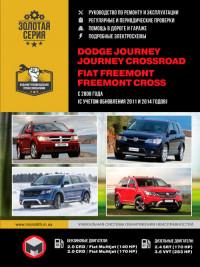
Руководство по эксплуатации и ремонту автомобилей Dodge Journey/Journey Crossroad и Fiat Freemont/Freemont Cross с 2008 года выпуска с бензиновыми и дизельными двигателями.
- Автор: —
- Издательство: Монолит
- Год издания: —
- Страниц: —
- Формат: —
- Размер: —

Подборка руководств по эксплуатации Fiat Freemont.
- Автор: —
- Издательство: Fiat Auto
- Год издания: 2012/2013
- Страниц: 424/516
- Формат: PDF
- Размер: 30,2 Mb

Вы здесь

ЭЛЕМЕНТЫ ПРИБОРНОЙ ПАНЕЛИ
(Рис. 2)
(Рис. 2)
1 — Отверстие для обдува боко-
вого окна
6 — Блок выключателей
11 — Кнопка пуска / останова
двигателя
2 — Воздуховыпускное отверстие 7 — Элементы управления сис-
темы Uconnect®
12 — Рычаг открытия капота
3 — Панель приборов
8 — Слот для карт памяти SD
13 — Переключатели света фар
4 — Система Uconnect®
9 — Розетка питания
14 — Переключатель света фар
5 — Перчаточный ящик
10 — Слот для подключения
проигрывателя CD / DVD-дисков
6
ЗНАКОМ-
СТВО С
АВТОМО-
БИЛЕМ
БЕЗОПАС-
НОСТЬ
ЗАПУСК
ДВИГАТЕЛЯ
И УПРАВЛЕ-
НИЕ АВТО-
МОБИЛЕМ
КОНТРОЛЬ-
НЫЕ ИНДИ-
КАТОРОЫ
И ПРЕД-
УПРЕЖ-
ДАЮЩИЕ
СООБЩЕНИЯ
В ЭКСТРЕН-
НОЙ
СИТУАЦИИ
ОБСЛУЖИ-
ВАНИЕ И
УХОД
ТЕХНИЧЕ-
СКИЕ
ХАРАКТЕ-
РИСТИКИ
ПРЕДМЕТНЫЙ
УКАЗАТЕЛЬ

ПРИБОРЫ
(Рис. 3)
1. Тахометр
Этот прибор измеряет обороты двигателя в
минуту (об./мин. х. 1000). До достижения ука-
зателем красной зоны, ослабьте нажим на пе-
даль акселератора для предотвращения пов-
реждения двигателя.
2. Спидометр
Показывает скорость автомобиля.
3. Уровень топлива
Датчик уровня топлива показывает уровень
топлива в баке, если замок зажигания нахо-
дится в положении ON/RUN.
(Рис. 3)
7
ЗНАКОМ-
СТВО С
АВТОМО-
БИЛЕМ
БЕЗОПАС-
НОСТЬ
ЗАПУСК
ДВИГАТЕЛЯ
И УПРАВЛЕ-
НИЕ АВТО-
МОБИЛЕМ
КОНТРОЛЬ-
НЫЕ ИНДИ-
КАТОРОЫ
И ПРЕД-
УПРЕЖ-
ДАЮЩИЕ
СООБЩЕНИЯ
В ЭКСТРЕН-
НОЙ
СИТУАЦИИ
ОБСЛУЖИ-
ВАНИЕ И
УХОД
ТЕХНИЧЕ-
СКИЕ
ХАРАКТЕ-
РИСТИКИ
ПРЕДМЕТНЫЙ
УКАЗАТЕЛЬ

4. Датчик температуры охлаждающей
жидкости
Датчик температуры показывает температуру
охлаждающей жидкости двигателя. Любые
показания в пределах нормальных значений
показывают, что система охлаждения рабо-
тает удовлетворительно. Стрелка датчика бу-
дет, скорее всего, показывать высокую темпе-
ратуру при движении в жаркую погоду, вверх
по горной дороге, в плотном потоке или при
движении с прицепом. Если указатель подни-
мается до отметки 9Н9, безопасно сверните на
обочину и остановите автомобиль. Если сис-
тема кондиционирования воздуха включена,
выключите ее. Кроме того, переключите ко-
робку передач на нейтральную передачу и ос-
тановите автомобиль. Если стрелка остается
на отметке 9Н9, немедленно выключите двига-
тель и обратитесь в сервисную службу.
Не оставляйте автомобиль с рабо-
тающим
двигателем
без
при-
смотра, поскольку вы не сможете
отреагировать на показания температуры
в случае перегрева двигателя.
КЛЮЧИ ОТ ВАШЕГО АВТОМОБИЛЯ
В вашем автомобиле используется система
зажигания без ключа. Эта система состоит из
брелока с передатчиком дистанционного уп-
равления замками (RKE) и узла зажигания без
ключа (KIN).
Функция бесключевого доступа в салон
автомобиля Keyless Enter-N-Go Feature™
Автомобиль оснащен функцией бесключевого
доступа в салон автомобиля Enter-N-Go™ . Для
получения дополнительной информации обра-
титесь к пункту 9Порядок запуска двигателя9 в
разделе 9Пуск и эксплуатация9.
УЗЕЛ ЗАЖИГАНИЯ БЕЗ КЛЮЧА (KIN)
Эта функция позволяет водителю управлять
выключателем зажигания посредством нажа-
тия на кнопку, если передатчик дистанцион-
ного управления замками (RKE) находится в
салоне автомобиля.
Узел зажигания без ключа (KIN) имеет четыре
рабочих положения, три из которых маркиро-
ваны и загорятся при включении. Эти три поло-
жения — LOCK/OFF (блокировка/выключено),
ACC (вспомогательное оборудование) и ON/RUN
(включение/работа). Четвертая позиция — START
(пуск). Во время пуска загорится положение
RUN.
8
ЗНАКОМ-
СТВО С
АВТОМО-
БИЛЕМ
БЕЗОПАС-
НОСТЬ
ЗАПУСК
ДВИГАТЕЛЯ
И УПРАВЛЕ-
НИЕ АВТО-
МОБИЛЕМ
КОНТРОЛЬ-
НЫЕ ИНДИ-
КАТОРОЫ
И ПРЕД-
УПРЕЖ-
ДАЮЩИЕ
СООБЩЕНИЯ
В ЭКСТРЕН-
НОЙ
СИТУАЦИИ
ОБСЛУЖИ-
ВАНИЕ И
УХОД
ТЕХНИЧЕ-
СКИЕ
ХАРАКТЕ-
РИСТИКИ
ПРЕДМЕТНЫЙ
УКАЗАТЕЛЬ

ПРИМЕЧАНИЕ: Если замок зажигания не по-
дает сигнала при нажатии кнопки, причиной
этого может быть разряженный аккумулятор
передатчика RKE (брелока). В этой ситуации
может быть использован дублирующий метод
для управления замком зажигания. Поместите
переднюю сторону (сторону, противополож-
ную ключу для чрезвычайных ситуаций) бре-
лока к кнопке ENGINE START / STOP (кнопка
пуска / останова двигателя) и нажмите ее для
управления замком зажигания.
(Рис. 4)
Брелок для ключей
Брелок также содержит передатчик дистанци-
онного управления замками (RKE) и ключ для
чрезвычайных ситуаций, который хранится в
задней части брелока.
Ключ для чрезвычайных ситуаций делает воз-
можным доступ в автомобиль при низком за-
ряде аккумулятора автомобиля или брелока.
Ключ для чрезвычайных ситуаций предназна-
чен также для запирания перчаточного ящика.
Вы можете оставить ключ для чрезвычайных
ситуаций у себя при парковке автомобиля слу-
жащим парковки.
(Рис. 4)
Узел зажигания без ключа (KIN)
1 — LOCK/OFF (блокировка/выключено)
2 — ACC (вспомогательное оборудование)
3 — ON/RUN (включение / работа)
9
ЗНАКОМ-
СТВО С
АВТОМО-
БИЛЕМ
БЕЗОПАС-
НОСТЬ
ЗАПУСК
ДВИГАТЕЛЯ
И УПРАВЛЕ-
НИЕ АВТО-
МОБИЛЕМ
КОНТРОЛЬ-
НЫЕ ИНДИ-
КАТОРОЫ
И ПРЕД-
УПРЕЖ-
ДАЮЩИЕ
СООБЩЕНИЯ
В ЭКСТРЕН-
НОЙ
СИТУАЦИИ
ОБСЛУЖИ-
ВАНИЕ И
УХОД
ТЕХНИЧЕ-
СКИЕ
ХАРАКТЕ-
РИСТИКИ
ПРЕДМЕТНЫЙ
УКАЗАТЕЛЬ
Комментарии
- Manuals
- Brands
- Fiat Manuals
- Automobile
- Freemont
- Owner’s handbook manual
-
Contents
-
Table of Contents
-
Bookmarks
Quick Links
F
R
E
E
M
O
N
T
F
I
A
T
O
W
N
E
R
H
A
N
D
B
O
O
K
Related Manuals for Fiat Freemont
Summary of Contents for Fiat Freemont
-
Page 2
Fiat Service authorised workshops you can find technicians who are trained by us, offering quality and professionalism for all your service requirements. Fiat workshops are always close to you for your servicing operations, repairs and seasonal checks and our experts will offer practical recommendations for keeping your car in the best possible condition. -
Page 4
All our Genuine Parts undergo rigorous testing, both in design and build stages, by specialists who check the use of cutting-edge materials and test their reliability. This guarantees performance and safety in the long term for both you and the passengers in your automobile. Always insist on a Genuine Part and check that it has been used. -
Page 5
• the Warranty Certificate with terms and conditions for maintaining its validity • the range of additional services available to Fiat customers. Enjoy the read. Happy motoring! This Owner Handbook describes all versions of the Fiat Freemont; please consider only the information relevant to your version, engine and configuration. -
Page 7
Operating this vehicle at excessive speeds or while VEHICLE intoxicated may result in loss of control, collision with Congratulations on selecting your new FIAT vehicle. Be other vehicles or objects, going off the road, or over- assured that it represents precision workmanship, dis- turning;… -
Page 8
IMPORTANT NOTICE NOTE: Be sure to read the Owner’s Manual first KNOWING before driving your vehicle and before attaching or ALL MATERIAL CONTAINED IN THIS PUBLICA- YOUR installing parts/accessories or making other modifica- VEHICLE TION IS BASED ON THE LATEST INFORMATION tions to the vehicle. -
Page 9
When it comes to service, remember that your autho- MESSAGES rized dealer knows your vehicle best, has the factory- trained technicians and genuine parts, and is interested IN AN in your satisfaction. EMERGENCY Copyright © FIAT Group Automobiles S.p.A. SERVICING AND CARE TECHNICAL SPECIFICATIONS CONTENTS… -
Page 10
Consult the following table for a description of the KNOWING symbols that may be used on your vehicle or through- YOUR out this Owner’s Manual: (fig. 1) VEHICLE SAFETY STARTING DRIVING WARNING LIGHTS MESSAGES IN AN EMERGENCY SERVICING AND CARE TECHNICAL SPECIFICATIONS CONTENTS… -
Page 11
VEHICLE MODIFICATIONS/ KNOWING ALTERATIONS YOUR VEHICLE WARNING! Any modifications or alterations to this SAFETY vehicle could seriously affect its road- worthiness and safety and may lead to a collision resulting in serious injury or death. STARTING DRIVING WARNING LIGHTS MESSAGES IN AN EMERGENCY SERVICING… -
Page 12
INSTRUMENT PANEL FEATURES KNOWING (fig. 2) YOUR VEHICLE SAFETY STARTING DRIVING WARNING LIGHTS MESSAGES IN AN EMERGENCY SERVICING AND CARE TECHNICAL (fig. 2) SPECIFICATIONS 1 — Side Window Demist Outlet 6 — Switch Bank 11 — Engine Start/Stop Button 2 — Air Outlet 7 —… -
Page 13
INSTRUMENTS KNOWING (fig. 3) YOUR VEHICLE 1. Tachometer 3. Fuel Gauge This gauge measures engine revolutions per minute The fuel gauge shows the level of fuel in the tank when SAFETY (RPM x 1000). Before the pointer reaches the red area, ignition switch is in the ON/RUN position. -
Page 14
A WORD ABOUT YOUR KEYS 4. Coolant Temperature Gauge KNOWING The temperature gauge indicates engine coolant tem- Your vehicle uses a keyless ignition system. This system YOUR perature. Any reading within the normal range indi- VEHICLE consists of a Key Fob with Remote Keyless Entry (RKE) cates that the cooling system is operating satisfactorily. -
Page 15
KEYLESS IGNITION NODE (KIN) NOTE: In case the ignition switch does not change KNOWING with the push of a button, the RKE transmitter (Key This feature allows the driver to operate the ignition YOUR Fob) may have a low or dead battery. In this situation a VEHICLE switch with the push of a button, as long as the Remote back up method can be used to operate the ignition… -
Page 16
KEY FOB NOTE: You can insert the double-sided emergency KNOWING key into the lock cylinders with either side up. The Key Fob also contains the Remote Keyless Entry YOUR VEHICLE (RKE) transmitter and an emergency key, which stores IGNITION OR ACCESSORY ON MESSAGE in the rear of the Key Fob. -
Page 17
SENTRY KEY® KNOWING WARNING! (Continued) The Sentry Key® Immobilizer system prevents unau- YOUR • Allowing children to be in a vehicle unattended VEHICLE thorized vehicle operation by disabling the engine. The is dangerous for a number of reasons. A child or system does not need to be armed or activated. -
Page 18
All of the Key Fobs provided with your new vehicle CUSTOMER KEY PROGRAMMING KNOWING have been programmed to the vehicle electronics. Programming Key Fobs or RKE transmitters may be YOUR VEHICLE performed at an authorized dealer. REPLACEMENT KEYS General Information NOTE: Only Key Fobs that are programmed to the The Sentry Key®… -
Page 19
REMOTE KEYLESS ENTRY (RKE) To Unlock The Doors And Liftgate KNOWING Press and release the UNLOCK button on the RKE The RKE system allows you to lock or unlock the YOUR VEHICLE transmitter once to unlock the driver’s door or twice doors and liftgate from distances up to approximately within five seconds to unlock all doors and liftgate. -
Page 20
Turn Headlights On With Remote Key Unlock NOTE: KNOWING This feature activates the headlights for up to 90 • Perchlorate Material — special handling may apply. YOUR VEHICLE seconds when the doors are unlocked with the RKE Batteries could contain dangerous materials. Please transmitter. -
Page 21
2. Insert the tip of the emergency key or a #2 flat blade 4. To assemble the RKE transmitter case, snap the two KNOWING screwdriver into the slot and gently pry the two halves together. YOUR halves of the RKE transmitter apart. Make sure not VEHICLE General Information to damage the seal during removal. -
Page 22
VEHICLE SECURITY ALARM • Press the LOCK button on the exterior Passive KNOWING Entry Door Handle with a valid Key Fob available in The Vehicle Security Alarm (VSA) system monitors the YOUR the same exterior zone (refer to «Keyless Enter-N- VEHICLE vehicle doors, hood, and liftgate for unauthorized en- Go™»… -
Page 23
NOTE: Vehicle Security Alarm will arm regardless of whether KNOWING you are in the vehicle or not. If you remain in the • The driver’s door key cylinder and the liftgate button YOUR vehicle and open a door, the alarm will sound. If this VEHICLE on the RKE transmitter cannot arm or disarm the occurs, disarm the Vehicle Security Alarm. -
Page 24
PREMIUM SECURITY SYSTEM (for TO ARM THE SYSTEM KNOWING versions/markets, where Follow these steps to arm the theft alarm: YOUR VEHICLE provided) 1. Make sure the vehicle ignition system is «OFF». (refer to «Starting Procedures» in «Starting And The Premium Security system monitors the doors, Driving»… -
Page 25
• The ultrasonic intrusion sensor (motion detector) NOTE: KNOWING actively monitors your vehicle every time you arm • The driver’s door key cylinder and the trunk button YOUR the security system. If you prefer, you can turn OFF VEHICLE on the RKE transmitter cannot arm or disarm the the ultrasonic intrusion sensor and vehicle tilt sensor Vehicle Security Alarm. -
Page 26
STEERING WHEEL LOCK ELECTRONIC VEHICLE KNOWING INFORMATION CENTER (EVIC) Your vehicle may be equipped with a passive electronic YOUR VEHICLE steering wheel lock. This lock prevents steering the The Electronic Vehicle Information Center (EVIC) fea- vehicle without the ignition key. If the steering wheel is tures a driver-interactive display that is located in the moved to one of the lock positions with the key in the instrument cluster. -
Page 27
• Tire Pressure • UP Arrow Button KNOWING YOUR • Vehicle Information Push and release the UP button to scroll VEHICLE upward through the main menus and • Warning Message Displays submenus. • Turn Menu OFF • DOWN Arrow Button SAFETY The system allows the driver to select information by Push and release the DOWN button to scroll… -
Page 28
ELECTRONIC VEHICLE INFORMATION • Unstored Messages KNOWING CENTER (EVIC) DISPLAYS This message type is displayed indefinitely or until the YOUR condition that activated the message is cleared. Ex- VEHICLE The EVIC display consists of three sections: amples of this message type are «Turn Signal On» (if a 1. -
Page 29
Left Front Turn Signal Light Out (with a single chime) Inflate Tire to XXX. Refer to information on «Tire KNOWING Pressure» and «Tire Pressure Monitor» in «Knowing YOUR Left Rear Turn Signal Light Out (with a single chime) Your Vehicle.» VEHICLE Right Front Turn Signal Light Out (with a single chime) Service TPM System (with a single chime). -
Page 30
Exhaust Service Required — See Dealer Now. The EVIC AMBER TELLTALE LIGHTS KNOWING engine will be de-rated to prevent permanent damage This area will show reconfigurable amber caution tell- YOUR to the after-treatment system. If this condition occurs, VEHICLE tales. These telltales include: it is necessary to have your vehicle serviced by your •… -
Page 31
• Electronic Stability Control OFF (ESC OFF) Indi- • Charging System Light KNOWING cator Light This light shows the status of the electrical YOUR This light indicates the Electronic Stability charging system. The light should come on when VEHICLE Control system (ESC) has been turned off by the ignition is first cycled ON and remain on briefly as the driver. -
Page 32
If a problem is detected, the light will come on while • Transmission Temperature Warning Light (for KNOWING the engine is running. Cycle the ignition key when the versions/markets, where provided) YOUR vehicle has completely stopped and the shift lever is This light indicates that the transmission fluid VEHICLE placed in the PARK position (for versions/markets,… -
Page 33
GEAR SHIFT INDICATOR (GSI) — (for When the shift down indicator (-) is shown on the KNOWING versions/markets, where provided) display, the GSI is advising the driver to engage a lower YOUR gear. (fig. 12) (fig. 13) VEHICLE The Gear Shift Indicator (GSI) system is enabled on vehicles with a manual transmission, or when a vehicle The GSI indicator in the EVIC remains illuminated until with an automatic transmission is in manual shift mode. -
Page 34
LIGHTS To turn off the message temporarily, press and release the BACK button. To reset the oil change indicator MESSAGES system please refer to a Fiat Dealership. (fig. 12) GSI Shift Down (-) Indicator — Automatic Transmission IN AN FUEL ECONOMY EMERGENCY Press and release the UP or DOWN button until “Fuel… -
Page 35
AVERAGE FUEL ECONOMY NOTE: Significant changes in driving style or vehicle KNOWING loading will greatly affect the actual drivable distance of Shows the average fuel economy since the last reset. YOUR the vehicle, regardless of the DTE displayed value. VEHICLE When the fuel economy is reset, the display will read “RESET”… -
Page 36
TRIP INFO ELAPSED TIME KNOWING Press and release the UP or DOWN button until “Trip Shows the total elapsed time of travel since the last YOUR VEHICLE Info” displays highlighted in the EVIC and press the reset. Elapsed time will increment when the ignition is SELECT button. -
Page 37
Uconnect® SETTINGS • Oil Temperature — for versions/markets, where KNOWING provided YOUR BUTTONS ON THE FACEPLATE Displays the actual oil temperature. VEHICLE Buttons on the faceplate are located on the left and • Oil Pressure — for versions/markets, where pro- right side of the Uconnect®… -
Page 38
NOTE: Only one touchscreen area may be selected at Display KNOWING a time. • Brightness YOUR VEHICLE Press the «Settings» button on the faceplate to access Press the Brightness button on the touchscreen to the Settings screen, use the Page Up/Down buttons on change this display. -
Page 39
• Mode (for versions/markets, where provided) • Voice Response (for versions/markets, where KNOWING Press the Mode button on the touchscreen to change provided) YOUR this display. When in this display you may select one of Press the Voice Response button on the touchscreen VEHICLE the auto display settings. -
Page 40
• Show Time Status (for versions/markets, where Sound Only or Sounds and Display button followed by KNOWING provided) pressing the arrow back button on the touchscreen. YOUR Press the Show Time Status button on the touchscreen VEHICLE • Hill Start Assist (for versions/markets, where to change this display. -
Page 41
• Illuminated Approach (for versions/markets, • Auto High Beams “SmartBeam™” (for versions/ KNOWING where provided) markets, where provided) YOUR Press the Illuminated Approach button on the touch- Press the Auto High Beams button on the touchscreen VEHICLE screen to change this display. When this feature is to change this display. -
Page 42
Doors & Locks with Lock button on the touchscreen, select On or Off KNOWING followed by pressing the arrow back button on the • Auto Lock (for versions/markets, where pro- YOUR touchscreen. VEHICLE vided) When this feature is selected, all doors will lock auto- •… -
Page 43
• Passive Entry (Keyless Enter-N-Go™) (for Engine Off Options KNOWING versions/markets, where provided) • Headlight Off Delay YOUR Press the Passive Entry button on the touchscreen to VEHICLE Press the Headlight Off Delay button on the touch- change this display. This feature allows you to lock and screen to change this display. -
Page 44
Compass Settings NOTE: Keep magnetic materials away from the top of KNOWING the instrument panel, such as iPod’s, Mobile Phones, • Variance (for versions/markets, where provided) YOUR Laptops and Radar Detectors. This is where the com- VEHICLE Press the Variance button on the touchscreen to pass module is located, and it can cause interference change this display. -
Page 45
• Calibration (for versions/markets, where pro- NOTE: Bass/mid/treble allow the you to simply slide KNOWING vided) your finger up/down to change the setting as well as YOUR Press the Calibration button to change this setting. press directly on the desired setting. VEHICLE This compass is self-calibrating, which eliminates the •… -
Page 46
Phone/Bluetooth® screen followed by pressing the arrow back button on KNOWING the touchscreen. • Paired Devices YOUR VEHICLE This feature shows which phones are paired to the NOTE: The usage of the Parade Mode feature will Phone/Bluetooth® system. For further information, cause the radio to activate the “Display Brightness refer to the Uconnect®… -
Page 47
• Set Language (for versions/markets, where pro- • Touchscreen Beep KNOWING vided) When in this display you may turn on or shut off the YOUR When in this display you may select a different language sound heard when a touchscreen button (button on VEHICLE for all display nomenclature, including the trip functions the touchscreen) is pressed. -
Page 48
• Set Time Hours Safety / Assistance KNOWING When in this display you may select the time display • Park Assist (for versions/markets, where pro- YOUR settings. To make your selection, press the Set Time VEHICLE vided) button on the touchscreen, adjust the hours using the The Rear Park Assist system will scan for objects up and down buttons on the touchscreen, followed by behind the vehicle when the transmission shift lever is… -
Page 49
• Hill Start Assist (for versions/markets, where • Headlights with Wipers (for versions/markets, KNOWING provided) where provided) YOUR When this feature is selected, the Hill Start Assist When this feature is selected, and the headlight switch VEHICLE (HSA) system is active. Refer to “Electronic Brake is in the AUTO position, the headlights will turn on Control System”… -
Page 50
• Flash Headlights With Lock (for versions/ • Flash Headlight with Lock (for versions/markets, KNOWING markets, where provided) where provided) YOUR When this feature is selected, the front and rear turn When this feature is selected, the front and rear turn VEHICLE signals will flash when the doors are locked or unlocked signals will flash when the doors are locked or unlocked… -
Page 51
NOTE: If the vehicle is equipped with Keyless Enter- Engine Off Options KNOWING N-Go™ (Passive Entry) and the EVIC is programmed • Engine Off Power Delay YOUR to Unlock All Doors 1st Press, all doors will unlock no VEHICLE When this feature is selected, the power window matter which Passive Entry equipped door handle is switches, radio, Uconnect®… -
Page 52
Compass Settings NOTE: Keep magnetic materials away from the top of KNOWING the instrument panel, such as iPod’s, Mobile Phones, • Variance (for versions/markets, where provided) YOUR Laptops and Radar Detectors. This is where the com- VEHICLE Compass Variance is the difference between Magnetic pass module is located, and it can cause interference North and Geographic North. -
Page 53
• Perform Compass Calibration (for versions/ NOTE: Bass/mid/treble allow the you to simply slide KNOWING markets, where provided) your finger up/down to change the setting as well as YOUR Press the Calibration button to change this setting. press directly on the desired setting. VEHICLE This compass is self-calibrating, which eliminates the •… -
Page 54
SEATS Adjusting The Seat Up Or Down KNOWING The height of the seats can be adjusted up or down. Pull Seats are a part of the Occupant Restraint System of YOUR VEHICLE upward or push downward on the seat switch, the seat the vehicle. -
Page 55
POWER LUMBAR (for versions/markets, WARNING! KNOWING where provided) YOUR • Adjusting a seat while driving may be VEHICLE The Power Lumbar switch is located on the outboard dangerous. Moving a seat while driving side of the driver’s seat. Push the switch forward to could result in loss of control which could cause a increase the lumbar support. -
Page 56
HEATED SEATS (for versions/markets, where NOTE: The engine must be running for the heated KNOWING provided) seats to operate. YOUR VEHICLE The front heated seats control buttons are located WARNING! within the Uconnect® system. You can gain access to the control buttons through the climate screen or the •… -
Page 57
uMANUAL FRONT SEAT ADJUSTMENTS WARNING! KNOWING For models equipped with manual seats, the driver and YOUR • Adjusting a seat while driving may be VEHICLE passenger seats can be adjusted forward or rearward dangerous. Moving a seat while driving by using a bar located by the front of the seat cushion, could result in loss of control which could cause a near the floor. -
Page 58
RECLINER ADJUSTMENT WARNING! KNOWING The recline lever is located on the outboard side of the YOUR • Adjusting a seat while the vehicle is VEHICLE seat. To recline the seat, lean forward slightly, lift the moving is dangerous.The sudden move- lever, lean back to the desired position and release the ment of the seat could cause you to lose control. -
Page 59
DRIVER’S SEAT HEIGHT ADJUSTMENT has a hardback surface that you can use as a work KNOWING surface when the seat is folded flat and the vehicle is The seat height control lever is located on the out- YOUR not in motion. (fig. -
Page 60
HEAD RESTRAINTS When AHRs deploy during a rear impact, the front half KNOWING of the head restraint extends forward to minimize the Head restraints are designed to reduce the risk of YOUR gap between the back of the occupant’s head and the VEHICLE injury by restricting head movement in the event of a AHR. -
Page 61
For comfort, the Active Head Restraints can be tilted • In the event of deployment of an Active Head Re- KNOWING forward and backward. To tilt the head restraint closer straint, refer to “Occupant Restraints/Supplemental YOUR to the back of your head, pull forward on the bottom of Active Head Restraints (AHR)/Resetting Active VEHICLE the head restraint. -
Page 62
NOTE: WARNING! KNOWING • The head restraints should only be removed by YOUR • Do not place items over the top of the VEHICLE qualified technicians, for service purposes only. If any Active Head Restraint, such as coats, of the head restraints require removal, see your seat covers or portable DVD players.These items authorized dealer. -
Page 63
60/40 SPLIT SECOND-ROW PASSENGER WARNING! KNOWING SEATS YOUR Driving a vehicle with the head re- VEHICLE To provide additional storage area, each second-row straints removed or improperly adjusted passenger seat can be folded flat. This allows for ex- could cause serious injury or death in the event of tended cargo space and still maintains some seating a collision.The head restraints should be checked SAFETY… -
Page 64
To Fold The Seat WARNING! KNOWING 1. Locate the control lever on the lower outboard side YOUR To prevent personal injury or damage to VEHICLE of the seat. (fig. 29) objects, keep your head, arms, and ob- jects out of the folding path of the seatback. 2. -
Page 65
Forward And Rearward Adjustment Recliner Adjustment KNOWING The control lever is on the outboard side of the seat. The recline lever is on the outboard side of the seat. To YOUR Lift the lever to move the seat forward or rearward. VEHICLE recline the seatback, lean back, lift the lever, position Release the lever once the seat is in the desired… -
Page 66
WARNING! WARNING! KNOWING YOUR • Adjusting a seat while the vehicle is Keep the latch clean and free of objects VEHICLE moving is dangerous.The sudden move- and be certain that the seatback/ ment of the seat could cause you to lose control. armrest is locked securely into position. -
Page 67
To Move The Second-Row Passenger Seat For- NOTE: A hand-grip is molded into the front of each KNOWING ward quarter trim panel near the door opening to assist YOUR entry and exit from the third-row passenger seats. VEHICLE NOTE: Raise the seatback/armrest before moving the seat to allow for full seat travel. -
Page 68
To Unfold And Move The Second-Row Passen- NOTE: Prior to folding the third-row passenger seat- KNOWING ger Seat Rearward back, make sure the second-row passenger seatback is YOUR not in a reclined position. This will allow the seatback VEHICLE Move the seatback rearward until it locks in place and to fold easily. -
Page 69
To Unfold The Seatback WARNING! KNOWING Grasp the assist strap loop on the seatback and pull it YOUR • Be certain that the seatback is locked VEHICLE toward you to raise the seatback. Continue to raise the securely into position. Otherwise, the seatback until it locks in place. -
Page 70
TILT/TELESCOPING STEERING WARNING! KNOWING COLUMN YOUR Do not adjust the steering column while VEHICLE This feature allows you to tilt the steering column driving. Adjusting the steering column upward or downward. It also allows you to lengthen or while driving or driving with the steering column shorten the steering column. -
Page 71
HEATED STEERING WHEEL (for WARNING! KNOWING versions/markets, where YOUR • Persons who are unable to feel pain to VEHICLE provided) the skin because of advanced age, The steering wheel contains a heating element that chronic illness, diabetes, spinal cord injury, medi- helps warm your hands in cold weather. -
Page 72
MIRRORS AUTOMATIC DIMMING MIRROR (for KNOWING versions/markets, where provided) YOUR INSIDE DAY/NIGHT MIRROR VEHICLE This mirror automatically adjusts for headlight glare from A two-point pivot system allows for horizontal and vehicles behind you. This feature will be defaulted on, and vertical adjustment of the mirror. -
Page 73
NOTE: The passenger side convex outside mirror will Models Without Express Window Feature KNOWING give a much wider view to the rear, and especially of the Press the mirror select button marked L (left) or R YOUR lane next to your vehicle. VEHICLE (right) and then press one of the four arrow buttons to move the mirror in the direction the arrow is pointing. -
Page 74
POWER FOLDING MIRRORS (for Resetting the Power Folding Outside Mirrors KNOWING versions/markets, where provided) You may need to reset the power folding mirrors if the YOUR VEHICLE The switch for the power folding mirrors is located following occurs: between the power mirror switches L (left) and R •… -
Page 75
HEATED MIRRORS (for versions/markets, Sun Visor “Slide-On Rod” Feature (for KNOWING where provided) versions/markets, where provided) YOUR VEHICLE This feature allows for additional flexibility in position- These mirrors are heated to melt frost or ice. ing the visor to block out the sun. This feature is activated whenever you turn on 1. -
Page 76
CLIMATE CONTROLS KNOWING YOUR CLIMATE CONTROLS VEHICLE The air conditioning and heating system is designed to make you comfortable in all types of weather. This system can be operated through either the instrument SAFETY panel or through the Uconnect® system display. When the Uconnect®… -
Page 77
Buttons On The Touchscreen 2. A/C Button KNOWING Press and release to change the current setting, the Buttons on the touchscreen are accessible on the YOUR indicator illuminates when A/C is ON. Performing this Uconnect® system screen. (fig. 45) (fig. 46) VEHICLE function again will cause the A/C operation to switch Button Descriptions (Applies To Both Buttons… -
Page 78
4. Front Defrost Button Failure to follow these cautions can KNOWING Press and release to change the current airflow setting YOUR cause damage to the heating elements: to Defrost mode. The indicator illuminates when this VEHICLE • Use care when washing the inside of feature is ON. -
Page 79
NOTE: Pressing this button while in Sync mode will Blower Control Knob On The Faceplate KNOWING automatically exit Sync. The blower speed increases as you turn the blower YOUR VEHICLE control knob clockwise from the lowest blower set- 8. Passenger Temperature Control Down Button ting. -
Page 80
• Bi-Level Mode 13. Driver Temperature Control Down Button KNOWING Air comes from the instrument panel outlets (Uconnect® 8.4 Only) YOUR and floor outlets. A slight amount of air is Provides the driver with independent temperature VEHICLE directed through the defrost and side window demister control. -
Page 81
CLIMATE CONTROL FUNCTIONS MAX A/C KNOWING MAX A/C sets the control for maximum cooling per- YOUR A/C (Air Conditioning) formance. VEHICLE The Air Conditioning (A/C) button allows the opera- Press and release to toggle between MAX A/C and the tor to manually activate or deactivate the air condition- prior settings. -
Page 82
NOTE: In cold weather, use of Recirculation mode Controlling The Rear Climate Controls From KNOWING may lead to excessive window fogging. The recircula- The Front Uconnect® Touchscreen YOUR tion feature may be unavailable (soft button greyed VEHICLE The Three-Zone climate control system allows for out). -
Page 83
To change the rear system settings: • To return to Front screen, press «REAR» button KNOWING again, or it will revert to the Front screen after six • Press «REAR» button to change control to rear YOUR seconds. VEHICLE control mode, Rear display (below) will appear. Con- trol functions now operate rear system. -
Page 84
Rear Blower Control Interior air enters the Rear Automatic KNOWING The rear blower control knob can be manually set to YOUR Temperature Control System through an VEHICLE off, or any fixed blower speed, by rotating the knob intake grille, located in the right side trim from low to high. -
Page 85
Rear Mode Control KNOWING • Headliner Mode YOUR VEHICLE Air comes from the outlets in the headliner. Each of these outlets can be individually adjusted to direct the flow of air. Moving the air vanes of the SAFETY outlets to one side will shut off the airflow. •… -
Page 86
Buttons On The Touchscreen 2. A/C Button KNOWING Press and release to change the current setting, the Buttons on the touchscreen are accessible on the YOUR indicator illuminates when A/C is ON. Performing this VEHICLE Uconnect® system screen. (fig. 52) (fig. 53) function again will cause the A/C operation to switch Button Descriptions (Applies To Both Buttons into manual mode and the A/C indicator will turn off. -
Page 87
4. AUTO Operation Button Failure to follow these cautions can KNOWING Automatically controls the interior cabin temperature YOUR cause damage to the heating elements: by adjusting airflow distribution and amount. Perform- VEHICLE • Use care when washing the inside of ing this function will cause the ATC to switch between the rear window. -
Page 88
8. Passenger Temperature Control Up Button control knob on the faceplate or buttons on the touch- KNOWING Provides the passenger with independent temperature screen as follows: YOUR control. Push the button for warmer temperature VEHICLE Blower Control Knob On The Faceplate settings. -
Page 89
• Bi-Level Mode 14. Driver Temperature Control Down Button KNOWING Air comes from the instrument panel outlets Provides the driver with independent temperature YOUR and floor outlets. A slight amount of air is control. Push the button for cooler temperature set- VEHICLE directed through the defrost and side window demister tings. -
Page 90
A/C (Air Conditioning) MAX A/C KNOWING The Air Conditioning (A/C) button allows the opera- MAX A/C sets the control for maximum cooling per- YOUR VEHICLE tor to manually activate or deactivate the air condition- formance. ing system. When the air conditioning system is turned Press and release to toggle between MAX A/C and the on, cool dehumidified air will flow through the outlets prior settings. -
Page 91
NOTE: In cold weather, use of Recirculation mode NOTE: KNOWING may lead to excessive window fogging. The recircula- • It is not necessary to move the temperature settings. YOUR tion feature may be unavailable (soft button greyed VEHICLE The system automatically adjusts the temperature, out). -
Page 92
The operator can also select the direction of the To change the rear system settings: KNOWING airflow by selecting one of the available mode settings. • Press the «REAR» button to change control to rear YOUR A/C operation and Recirculation control can also be VEHICLE control mode, Rear display (below) will appear. -
Page 93
Rear Lock The rear ATC is located in the headliner, near the KNOWING center of the vehicle. Pressing the Rear Temperature Lock button on the YOUR VEHICLE Uconnect® touchscreen, illuminates a lock symbol in • Press the Rear Temperature Lock button on the the rear display. -
Page 94
NOTE: It is not necessary to move the temperature Interior air enters the Rear Automatic KNOWING settings for cold or hot vehicles. The system automati- YOUR Temperature Control System through an cally adjusts the temperature, mode and fan speed to VEHICLE intake grille, located in the right side trim provide comfort as quickly as possible. -
Page 95
DRIVING outlets to one side will shut off the airflow. Technology) coolant that meets the requirements of WARNING Fiat Classification 9.55522 and 50% water is recom- • Bi-Level Mode LIGHTS mended. Refer to “Maintenance Procedures” in “Ser- Air comes from both the headliner outlets and MESSAGES vice and Care”… -
Page 96
Window Fogging Outside Air Intake KNOWING Interior fogging on the windshield can be quickly re- Make sure the air intake, located directly in front of the YOUR moved by turning the mode selector to Defrost. The windshield, is free of obstructions such as leaves. VEHICLE Defrost/Floor mode can be used to maintain a clear Leaves collected in the air intake may reduce airflow,… -
Page 97
Manual Control Setting Suggestions For Various Weather Conditions KNOWING (fig. 57) YOUR VEHICLE SAFETY STARTING DRIVING WARNING LIGHTS MESSAGES IN AN EMERGENCY SERVICING AND CARE TECHNICAL SPECIFICATIONS CONTENTS (fig. 57) -
Page 98
LIGHTS AUTOMATIC HEADLIGHTS (for KNOWING versions/markets, where provided) YOUR HEADLIGHT SWITCH VEHICLE This system automatically turns the headlights on or off according to ambient light levels. To turn the system The headlight switch is located on the drivers on, rotate the headlight switch counterclockwise to side of the instrument panel. -
Page 99
To operate, rotate the headlight leveling switch until NOTE: The Headlights On with Wipers feature can be KNOWING the appropriate number, which corresponds to the turned on and off using the Uconnect® System, refer YOUR load listed on the following chart, illuminates on the to “Uconnect®… -
Page 100
LIGHTS-ON REMINDER Front Fog Lights KNOWING If the headlights or parking lights are on after the To activate the front fog lights, turn on the YOUR VEHICLE ignition is placed in the OFF position, a chime will parking lights or the low beam headlights and sound to alert the driver when the driver’s door is press the headlight switch. -
Page 101
MULTIFUNCTION LEVER NOTE: KNOWING The multifunction lever controls the operation of the • If either light remains on and does not flash, or there YOUR VEHICLE turn signals, headlight beam selection and passing lights. is a very fast flash rate, check for a defective outside The multifunction lever is located on the left side of the light bulb. -
Page 102
INTERIOR LIGHTS Rotating the dimmer control upward with the parking KNOWING lights or headlights on will increase the brightness of The interior lights come on when a door is opened. YOUR the instrument panel lights. VEHICLE To protect the battery, the interior lights will turn off automatically 10 minutes after the ignition switch is DOME LIGHT POSITION moved to the LOCK position. -
Page 103
ILLUMINATED ENTRY WINDSHIELD WIPERS AND KNOWING WASHERS The courtesy lights will turn on when you use the YOUR VEHICLE Remote Keyless Entry (RKE) transmitter to unlock the The windshield wiper/washer control lever is located doors or open any door or liftgate. on the left side of the steering column. -
Page 104
INTERMITTENT WIPER SYSTEM NOTE: The wiper delay times depend on vehicle KNOWING speed. If the vehicle is moving less than 16 km/h, delay Use the intermittent wiper system when weather con- YOUR times will be doubled. VEHICLE ditions make a single wiping cycle, with a variable pause between cycles, desirable. -
Page 105
NOTE: The wipers will automatically return to the WINDSHIELD WASHERS KNOWING “park” position if you turn OFF the ignition switch To use the windshield washer, push the washer knob, YOUR while they are operating. The wipers will resume op- VEHICLE located on the end of the multifunction lever, inward to eration when you turn the ignition switch back to the the second detent. -
Page 106
HEADLIGHT WASHERS (for MIST FEATURE KNOWING versions/markets, where Push the washer knob, located on the end of the YOUR VEHICLE multifunction lever, inward to the first detent to acti- provided) vate a single wipe cycle to clear the windshield of road The Headlight Washers are recessed into the top of mist or spray from a passing vehicle. -
Page 107
REAR WINDOW FEATURES Rotate the switch upward past the first detent KNOWING position to activate the rear washer. The washer YOUR REAR WINDOW WIPER/WASHER pump will continue to operate as long as the switch is VEHICLE The rear window wiper/washer control is located on held. -
Page 108
NOTE: To prevent excessive battery drain, use the • Turn the rear wiper off when driving KNOWING rear window defroster only when the engine is oper- YOUR through an automatic car wash. Damage ating. VEHICLE to the rear wiper may result if the rear wiper switch is left in the ON position. -
Page 109
ELECTRONIC SPEED CONTROL TO ACTIVATE KNOWING Push the ON/OFF button. The Cruise Indicator Light When engaged, the Electronic Speed Control takes YOUR VEHICLE in the instrument cluster will illuminate. To turn the over accelerator operations at speeds greater than system off, push the ON/OFF button a second time. 40 km/h. -
Page 110
TO DEACTIVATE To Decrease Speed KNOWING A soft tap on the brake pedal, pushing the CANCEL When the Electronic Speed Control is set, you can YOUR VEHICLE button, or normal brake pressure while slowing the decrease speed by pushing the SET (-) button. vehicle will deactivate the Electronic Speed Control •… -
Page 111
OVERHEAD CONSOLE Using Electronic Speed Control On Hills KNOWING The transmission may downshift on hills to maintain The overhead console contains courtesy/reading lights, YOUR VEHICLE the vehicle set speed. storage for sunglasses, an interior observation mirror and an optional power sunroof switch. (fig. -
Page 112
COURTESY/READING LIGHTS SUNGLASSES STORAGE KNOWING The overhead console has two courtesy lights. The To access the storage compartment, press on the YOUR VEHICLE lights turn on when a door or the liftgate is opened. If raised bars on the compartment door in the center of your vehicle is equipped with Remote Keyless Entry the console and release and the door will swing (RKE) the lights will also turn on when the UNLOCK… -
Page 113
HAZARD WARNING FLASHERS NOTE: From the “observation mirror” position, the KNOWING door can only be closed. The Hazard Warning flasher switch is located in the YOUR VEHICLE To return to the full open position, the door must first instrument panel switch bank, above the climate be closed and then opened by pressing the latch again controls. -
Page 114
STORAGE KNOWING YOUR GLOVE COMPARTMENT VEHICLE The glove compartment is located on the passenger side of the instrument panel. Pull on the release handle to open the glove compartment. SAFETY (fig. 72) FLOOR CONSOLE STORAGE An open storage area, or cubby bin, is located in the STARTING floor console. -
Page 115
Pull upward on the release handle, located on the front WARNING! KNOWING of the lid, to gain access to the storage tray and storage YOUR Do not operate this vehicle with a con- compartment. (fig. 75) VEHICLE sole compartment lid in the open posi- The storage tray can be slid forward and rearward or tion. -
Page 116
Sliding Armrest (for automatic transmission NOTE: Make sure that objects inside the bin do not KNOWING only) interfere with the latch before closing the seat. Push YOUR the seat cushion downward after closing it to make VEHICLE The center console armrest can also be slid rearward sure it latches to the base. -
Page 117
SECOND-ROW PASSENGER SEAT IN-FLOOR STORAGE BIN WITH KNOWING TEMPORARY STORAGE BIN REMOVABLE LINER YOUR VEHICLE This is a temporary storage bin designed for use when NOTE: Position the front seat to at least a mid-track the seatback/armrest is down. Be sure to remove all position to provide easier access to the storage bin. -
Page 118
ELECTRICAL POWER OUTLETS The liner can be removed for easy cleaning. (fig. 81) KNOWING A 12 Volt (13 Amp) power outlet is located in the YOUR VEHICLE center console below the radio. The power outlet has power available when the ignition switch in the ON/ RUN or ACC position. -
Page 119
A second 12 Volt (13 Amp) power outlet is located KNOWING inside the center console storage area. Power is avail- YOUR able with the ignition switch in the ON/RUN, ACC or VEHICLE LOCK position. (fig. 83) A third fused 12 Volt power outlet is located on the SAFETY back of the center console. -
Page 120
• Do not exceed the maximum power of WARNING! KNOWING YOUR 160Watts (13 Amps) at 12Volts.If the 160 To avoid serious injury or death: VEHICLE Watt (13 Amp) power rating is exceeded • Only devices designed for use in this type the fuse protecting the system will need to be of outlet should be inserted into any 12 Volt outlet. -
Page 121
CUPHOLDERS • Many accessories that can be plugged KNOWING There are two cupholders, located in the center floor YOUR in draw power from the vehicle’s battery, VEHICLE console, for the front passengers. even when not in use (i.e., cellular (fig. 87) phones, etc.). -
Page 122
When the armrest is folded flat the cupholders are in In addition to cupholders, vehicles may also be KNOWING the back of the Head Restraint. The Head Restraint can equipped with bottle holders. The bottle holders are YOUR be adjusted to better position the cupholders. located on the door trim panels. -
Page 123
POWER SUNROOF (for WARNING! KNOWING versions/markets, where YOUR • Never leave children unattended in a VEHICLE provided) vehicle, or with access to an unlocked The power sunroof switch is located between the sun vehicle. Never leave the Key Fob in or near the visors on the overhead console. -
Page 124
OPENING SUNROOF — EXPRESS PINCH PROTECT FEATURE KNOWING Press the switch rearward and release it within one-half This feature will detect an obstruction in the opening YOUR VEHICLE second and the sunroof will open automatically from of the sunroof during Express Close operation. If an any position. -
Page 125
DOOR LOCKS minimized. If the buffeting occurs with the rear win- KNOWING dows open, open the front and rear windows together YOUR MANUAL DOOR LOCKS to minimize the buffeting. If the buffeting occurs with VEHICLE To lock each door, push the door lock knob on each the sunroof open, adjust the sunroof opening to mini- door trim panel downward. -
Page 126
POWER DOOR LOCKS WARNING! KNOWING A power door lock switch is on each front door trim YOUR • For personal security and safety in the VEHICLE panel. Use this switch to lock or unlock the doors and event of a collision, lock the vehicle liftgate. -
Page 127
Automatic Door Locks — (for versions/ NOTE: Use the Automatic Unlock Doors On Exit KNOWING markets, where provided) feature in accordance with local laws. YOUR VEHICLE The auto door lock feature default condition is dis- Automatic Unlock Doors On Exit abled. -
Page 128
To Engage The Child-Protection Door Lock WARNING! KNOWING System YOUR Avoid trapping anyone in a vehicle in a VEHICLE 1. Open the rear door. collision. Remember that the rear doors can only be opened from the outside when the 2. Insert the tip of the emergency key (or alike) into Child-Protection locks are engaged. -
Page 129
KEYLESS ENTER-N-GO™ To Disengage The Child-Protection Door Lock KNOWING System The Passive Entry system is an enhancement to the YOUR VEHICLE 1. Open the rear door. vehicle’s Remote Keyless Entry (RKE) system and a feature of Keyless Enter-N-Go™. This feature allows 2. -
Page 130
To Unlock From The Driver’s Side: To Unlock From The Passenger Side: KNOWING With a valid Passive Entry RKE transmitter within 1.5 With a valid Passive Entry RKE transmitter within 1.5 YOUR VEHICLE m of the driver’s door handle, grab the driver’s front m of the passenger door handle, grab the front passen- door handle to unlock the driver’s door automatically. -
Page 131
horn three times (on the third attempt ALL doors will To Lock The Vehicle’s Doors KNOWING lock and the Passive Entry RKE transmitter can be With one of the vehicle’s Passive Entry RKE transmit- YOUR locked in the vehicle). VEHICLE ters within 1.5 m of the driver or passenger front door To Enter The Liftgate handle, press the door handle LOCK button to lock all… -
Page 132
Do NOT grab the door handle, when pressing the door • If Passive Entry is disabled using Uconnect® System, KNOWING handle lock button. This could unlock the door(s). the key protection described in «Preventing Inadver- YOUR tent Locking of Passive Entry RKE Transmitter in (fig. -
Page 133
WINDOWS NOTE: For vehicles equipped with the Uconnect®, KNOWING the power window switches will remain active for up to YOUR POWER WINDOWS 10 minutes after the ignition is cycled to the LOCK/ VEHICLE The window controls on the driver’s door trim panel OFF position. -
Page 134
AUTO-DOWN FEATURE NOTE: KNOWING The driver’s power window switch has an Auto-down • If the window runs into any obstacle during Auto- YOUR VEHICLE feature. Press the window switch past the first detent, closure, it will reverse direction and then go back release, and the window will go down automatically. -
Page 135
2. Push the window switch down firmly to the second WIND BUFFETING KNOWING detent to open the window completely and con- Wind buffeting can be described as the perception of YOUR tinue to hold the switch down for an additional two VEHICLE pressure on the ears or a helicopter-type sound in the seconds after the window is fully open. -
Page 136
LIFTGATE NOTE: KNOWING The liftgate can be unlocked or locked pushing the • In the event of a power malfunction to the liftgate, an YOUR VEHICLE UNLOCK or LOCK button on the Remote Keyless emergency liftgate latch release can be used to open Entry (RKE) transmitter, the Keyless Enter-N-Go™… -
Page 137
CARGO AREA FEATURES WARNING! KNOWING YOUR RECHARGEABLE FLASHLIGHT (for • Driving with the liftgate open can al- VEHICLE low poisonous exhaust gases into your versions/markets, where provided) vehicle. These fumes could injure you and your The rechargeable LED flashlight stores in its charging passengers.Keep the liftgate closed when you are station in the left rear quarter trim panel. -
Page 138
To operate the flashlight, press the switch once for • 60/40 split second-row passenger seats with fold flat KNOWING high, twice for low, and a third time to return to off. feature, which allows for extended cargo space. Re- YOUR fer to “Seats”… -
Page 139
CARGO TIE-DOWNS WARNING! KNOWING YOUR The weight and position of cargo and WARNING! VEHICLE passengers can change the vehicle cen- Cargo tie-downs are not safe anchors for ter of gravity and vehicle handling.To avoid loss of a child seat tether strap.In a sudden stop control resulting in personal injury, follow these SAFETY or collision, a tie-down could pull loose and allow… -
Page 140
RETRACTABLE CARGO AREA COVER — To install the cover, position it in the vehicle so that the KNOWING FIVE PASSENGER MODELS (for flat side of the housing faces upward. Then, insert YOUR versions/markets, where provided) either the left or the right spring-loaded post (located VEHICLE on the ends of the cover housing) into the left attach- NOTE: The purpose of this cover is for privacy, not to… -
Page 141
Grab the cover handle and pull it toward you. As the WARNING! KNOWING cover nears the liftgate opening, guide the rear attach- YOUR A cargo cover that is unsecured in the ment posts (on both ends of the cover) into the VEHICLE vehicle could cause injury in a collision.It notches in the trim panels. -
Page 142
TO OPEN AND CLOSE THE HOOD KNOWING Two latches must be released to open the hood. YOUR VEHICLE 1. Pull the hood release lever located under the left side of the instrument panel. (fig. 108) SAFETY 2. Outside of the vehicle, locate the safety latch lever near the center of the grille between the grille and hood opening. -
Page 143
Failure to follow IN AN Metal Crossbars can be purchased from your FIAT EMERGENCY this warning could result in serious injury or dealer to provide a functional roof rack system. -
Page 144
To Move The Crossbars 3. Tighten the knobs on each crossbar to lock it in KNOWING position. As you tighten the knob, make sure the 1. Loosen the knobs on top of each crossbar approxi- YOUR clamp tooth engages completely into the side rail VEHICLE mately six turns to disengage the clamp tooth from slot. -
Page 145
• To prevent damage to the roof of your WARNING! KNOWING YOUR vehicle, DO NOT carry any loads on the Cargo must be securely tied before driv- VEHICLE roof rack without the crossbars installed. ing your vehicle. Improperly secured The load should be secured and placed on top of loads can fly off the vehicle, particularly at high the crossbars, not directly on the roof. -
Page 146
BRAKE SYSTEM WARNING! KNOWING YOUR • Riding the brakes can lead to brake VEHICLE Your vehicle is equipped with dual hydraulic failure and possibly a collision. Driving brake systems. If either of the two hydraulic with your foot resting or riding on the brake systems loses normal capability, the remaining system pedal can result in abnormally high brake tem- SAFETY… -
Page 147
ELECTRONIC BRAKE CONTROL ANTI-LOCK BRAKE SYSTEM (ABS) KNOWING SYSTEM This system aids the driver in maintaining vehicle con- YOUR VEHICLE trol under adverse braking conditions. The system Your vehicle is equipped with an advanced electronic controls hydraulic brake pressure to prevent wheel brake control system commonly referred to as ESC. -
Page 148
ABS is activated during braking under certain road or KNOWING WARNING! (Continued) stopping conditions. ABS-inducing conditions can in- YOUR • Pumping of the Anti-Lock Brakes will diminish clude ice, snow, gravel, bumps, railroad tracks, loose VEHICLE their effectiveness and may lead to an accident. debris, or panic stops. -
Page 149
Anti-Lock Brake Light BRAKE ASSIST SYSTEM (BAS) KNOWING The BAS is designed to optimize the vehicle’s braking YOUR The Anti-Lock Brake Light monitors the ABS. VEHICLE capability during emergency braking maneuvers. The The light will turn on when the ignition system detects an emergency braking situation by sens- switch is turned to the ON position and may ing the rate and amount of brake application and then… -
Page 150
TRACTION CONTROL SYSTEM (TCS) other factors, such as road conditions, leaving the KNOWING roadway, or striking objects or other vehicles. This system monitors the amount of wheel spin of each YOUR VEHICLE of the driven wheels. If wheel spin is detected, brake WARNING! pressure is applied to the slipping wheel(s) and engine power is reduced to provide enhanced acceleration… -
Page 151
applies the brake of the appropriate wheel to assist in ESC Operating Modes KNOWING counteracting the condition of over-steer or under- The ESC system has two available operating modes. YOUR steer. VEHICLE Full On • Over-steer — when the vehicle is turning more than This is the normal operating mode for ESC. -
Page 152
Partial Off NOTE: To improve the vehicle’s traction when driving KNOWING with snow chains, or when starting off in deep snow, The “ESC OFF” button is located in the switch bank YOUR sand, or gravel, it may be desirable to switch to the VEHICLE above the climate control. -
Page 153
ESC ACTIVATION/MALFUNCTION NOTE: KNOWING INDICATOR LIGHT AND ESC OFF • The “ESC Activation/Malfunction Indicator Light” YOUR INDICATOR LIGHT VEHICLE and the “ESC OFF Indicator Light” come on momen- tarily each time the ignition switch is turned ON. The “ESC Activation/Malfunction Indicator •… -
Page 154
HSA Activation Criteria WARNING! KNOWING The following criteria must be met in order for HSA to YOUR • If you use a trailer brake controller VEHICLE activate: with your trailer, your trailer brakes may • Vehicle must be stopped. be activated and deactivated with the brake switch. -
Page 155
ONBOARD DIAGNOSTIC SYSTEM — TRAILER SWAY CONTROL (TSC) KNOWING OBD II TSC uses sensors in the vehicle to recognize an exces- YOUR VEHICLE sively swaying trailer. TSC activates automatically once Your vehicle is equipped with a sophisticated onboard the excessively swaying trailer is recognized. When diagnostic system called OBD II. -
Page 156
POWER STEERING Prolonged operation of the steering sys- KNOWING The standard power steering system will give you good YOUR tem at the end of the steering wheel VEHICLE vehicle response and increased ease of maneuverability travel will increase the steering fluid tem- in tight spaces. -
Page 157
TIRE PRESSURE MONITOR SYSTEM Do not use chemical flushes in your KNOWING (TPMS) YOUR power steering system as the chemicals VEHICLE can damage your power steering compo- The Tire Pressure Monitor System (TPMS) will warn nents. Such damage is not covered by the New the driver of a low tire pressure based on the vehicle Vehicle Limited Warranty. -
Page 158
The TPMS will warn the driver of a low tire pressure if • The TPMS has been optimized for the KNOWING the tire pressure falls below the low-pressure warning YOUR original equipment tires and wheels. limit for any reason, including low temperature effects VEHICLE TPMS pressures and warning have been and natural pressure loss through the tire. -
Page 159
NOTE: BASE SYSTEM KNOWING The Tire Pressure Monitor System (TPMS) uses wire- • The TPMS is not intended to replace normal tire care YOUR VEHICLE less technology with wheel rim mounted electronic and maintenance, or to provide warning of a tire sensors to monitor tire pressure levels. -
Page 160
NOTE: When filling warm tires, the tire pressure may 3. Lots of snow or ice around the wheels or wheel KNOWING need to be increased to an additional 0.3 BAR above housings. YOUR the recommended cold placard pressure in order to VEHICLE 4. -
Page 161
5. Once you repair or replace the original road tire and To reactivate the TPMS, first, replace all four wheel and KNOWING reinstall it on the vehicle in place of the compact tire assemblies (road tires) with those equipped with YOUR spare, the TPMS will update automatically and the TPM Sensors. -
Page 162
Tire Pressure Monitoring Low Pressure ServiceTPMS Warning KNOWING Warnings When a system fault is detected, the Tire Pressure YOUR VEHICLE Monitoring Telltale Light will flash on and off for 75 The Tire Pressure Monitoring Telltale Light will seconds and then remain on solid. The system fault will illuminate in the instrument cluster and a chime also sound a chime. -
Page 163
The EVIC will also display a «SERVICE TPM SYSTEM» 3. After driving the vehicle for up to 20 minutes above KNOWING message for a minimum of five seconds when a system 25 km/h, the TPMS Telltale Light will flash on and off YOUR fault related to an incorrect sensor location fault is for 75 seconds and then remain on solid. -
Page 164
TPMS Deactivation And Reactivation To reactivate the TPMS, first, replace all four wheel and KNOWING tire assemblies (road tires) with those equipped with The TPMS can be deactivated if replacing all four wheel YOUR TPM Sensors. Then, drive the vehicle for up to 20 VEHICLE and tire assemblies (road tires) with wheel and tire minutes above 25 km/h. -
Page 165
REAR PARK ASSIST (for PARK ASSIST SENSORS KNOWING versions/markets, where The four Park Assist sensors, located in the rear YOUR VEHICLE provided) fascia/bumper, monitor the area behind the vehicle that is within the sensors’ field of view. The sensors can The Rear Park Assist system provides visual and audible detect obstacles from approximately 30 cm up to 200 indications of the distance between the rear fascia and… -
Page 166
PARK ASSIST DISPLAY The system will indicate a detected obstacle by show- KNOWING ing three solid arcs and will produce a one-half second When the vehicle is in REVERSE, the warning display YOUR tone. As the vehicle moves closer to the object, the VEHICLE will turn ON indicating the system status. -
Page 167
KNOWING YOUR VEHICLE SAFETY STARTING DRIVING WARNING LIGHTS MESSAGES (fig. 115) Slow Tone IN AN EMERGENCY SERVICING AND CARE TECHNICAL SPECIFICATIONS CONTENTS (fig. 116) (fig. 117) Fast Tone Continuous Tone… -
Page 168
The vehicle is close to the obstacle when the warning KNOWING display shows one flashing arc and sounds a continuous YOUR tone. The following chart shows the warning alert VEHICLE operation when the system is detecting an obstacle: SAFETY WARNING ALERTS Rear Distance Greater than 200-100 cm… -
Page 169
If “CLEAN PARK ASSIST” appears in the Electronic • When you turn Park Assist off, the EVIC will display KNOWING Vehicle Information Center (EVIC) make sure the “PARK ASSIST SYSTEM OFF.” Furthermore, once YOUR outer surface and the underside of the rear fascia/ you turn Park Assist off, it remains off until you turn VEHICLE bumper is clean and clear of snow, ice, mud, dirt or… -
Page 170
• Park Assist is only a parking aid and it is KNOWING WARNING! (Continued) YOUR unable to recognize every obstacle, in- • Before using Park Assist, it is strongly recom- VEHICLE cluding small obstacles. Parking curbs mended that the ball mount and hitch ball as- might be temporarily detected or not detected at sembly is disconnected from the vehicle when the all. -
Page 171
PARKVIEW® REAR BACK UP speed exceeds 13 km/h, the transmission is shifted into KNOWING CAMERA (for versions/markets, «PARK» or the vehicle’s ignition is cycled to the OFF YOUR position. VEHICLE where provided) Static grid lines will illustrate the width of the vehicle Your vehicle may be equipped with the ParkView®… -
Page 172
NAVIGATION SYSTEM (for WARNING! KNOWING versions/markets, where YOUR Drivers must be careful when backing up VEHICLE provided) even when using the ParkView® Rear Back Up Camera.Always check carefully behind Refer to your Uconnect® User Manual. your vehicle, and be sure to check for pedestri- SAFETY ans, animals, other vehicles, obstructions, or blind spots before backing up.You are responsible for… -
Page 173
SOUND SYSTEMS STEERING WHEEL AUDIO KNOWING CONTROLS Refer to your Uconnect® User Manual. YOUR VEHICLE The remote sound system controls are located on the rear surface of the steering wheel. The left and right- hand controls are rocker-type switches with a pushbut- SAFETY ton in the center of each switch. -
Page 174
UCONNECT® MULTIMEDIA VIDEO LEFT -HAND SWITCH FUNCTIONS FOR KNOWING RADIO OPERATION ENTERTAINMENT SYSTEM (VES™) YOUR VEHICLE (for versions/markets, where • Push the top of the switch to SEEK the next listen- able station up from the current setting. provided) • Push the bottom of the switch to SEEK the next Your rear seat Video Entertainment System (VES™) is SAFETY listenable station down from the current setting. -
Page 175
Video Screen Play Video Games KNOWING Connect the video game console to the Auxiliary RCA YOUR NOTE: Typically there are two different ways to VEHICLE input jacks located on the back of the center console. operate the features of the Video Entertainment Sys- tem (VES™). -
Page 176
Using The Remote Control Using The Remote Control KNOWING 1. Push the MODE button on the Remote Control. 1. Push the MODE button on the Remote Control and YOUR VEHICLE the Mode Select Screen will display, unless a video is 2. -
Page 177
Important Notes For Single Video Screen Using The Remote Control KNOWING System 1. Push the MODE button on the Remote Control. YOUR VEHICLE • VES™ is able to transmit two channels of stereo 2. While looking at the Video Screen, highlight DISC audio simultaneously. -
Page 178
Using The Touchscreen Radio Controls Remote Control Operation KNOWING Quick Reference Chart 1. Press the “Player” button on the touchscreen. YOUR VEHICLE This chart provides a quick reference of the remote 2. Press the “Rear Entertainment” button on the control button functions for the different radio modes touchscreen to display the Rear Entertainment and menu screens. -
Page 179
Standard Screens Menu Screens KNOWING Remote Con- AM/FM/ DISC Mode YOUR Screen VEHICLE trol Button MW/LW AUX/AUX1/AUX2 Select Setup Menu Power Screen ON/OFF SAFETY Light Remote Backlight ON/OFF Audio: Next Track Video Play: Next STARTING Next Selection Selection Up Arrow Next Chapter Seek Up* Track… -
Page 180
Standard Screens Menu Screens KNOWING Remote Con- YOUR AM/FM/ DISC Mode Screen VEHICLE trol Button MW/LW AUX/AUX1/AUX2 Select Setup Menu Audio: Show Numeric SAFETY Show Entry Show Activate Numeric Enter Numeric Video Play: Not Available Selected Entry Available Available Entry Menu* Item Video Menu: Activate STARTING… -
Page 181
Standard Screens Menu Screens KNOWING Remote Con- AM/FM/ DISC Mode YOUR Screen VEHICLE trol Button MW/LW AUX/AUX1/AUX2 Select Setup Menu Audio: Pause if playing/ SAFETY resume Pause if playing, Video Play: Pause if Play/Pause Not Available else re- playing/resume Available Available Available STARTING… -
Page 182
Standard Screens Menu Screens KNOWING Remote Con- YOUR AM/FM/ DISC Mode Screen VEHICLE trol Button MW/LW AUX/AUX1/AUX2 Select Setup Menu Next Next Disc (if player is Prog Up SAFETY Preset* Available changer) Available Available Available Previous Previous Disc (if player is Prog Down Preset* Available… -
Page 183
5. ▸▸ – In radio modes, press to seek the next tunable 12. SLOW – Press to slow playback of a DVD disc. KNOWING station. In disc modes, press and hold to fast for- Press play (▸) to resume normal play. YOUR ward through the current audio track or video VEHICLE… -
Page 184
18. ENTER – Press to select the highlighted option in Locking The Remote Control KNOWING a menu. All remote control functionality can be disabled as a YOUR VEHICLE parental control feature. 19. ▴ / NEXT – In radio modes, press to select to the next station. -
Page 185
Replacing The Remote Control Batteries Controls KNOWING The remote control requires two AAA batteries for The headphone power indicator and controls are lo- YOUR VEHICLE operation. To replace the batteries: cated on the right ear cup. • Locate the battery compartment on the back of the NOTE: The rear video system must be turned on remote, then slide the battery cover downward. -
Page 186
Changing The Audio Mode For Headphones Replacing The Headphone Batteries KNOWING Each set of headphones requires two AAA batteries for 1. Ensure the Remote Control channel/screen selec- YOUR VEHICLE operation. To replace the batteries: tor switch is in the same position as the headphone selector switch. -
Page 187
What Does This Warranty Not Cover? This war- What Will Unwired® Do? Unwired®, at its option, KNOWING ranty does not cover any damage or defect that results will repair or replace any defective Product. Unwired® YOUR from misuse, abuse or modification of the Product reserves the right to replace any discontinued Product VEHICLE other than by Unwired. -
Page 188
Only Channel 1 displays video images. When in video In a two-screen system, the video for Channel 1 is KNOWING mode the image is displayed on the full screen, however displayed on the first rear seat screen and the video for YOUR Channel 2’s functionality is still available. -
Page 189
System Information • Channel 2 Mode — Displays the current source for KNOWING Channel 2. YOUR Information Mode Display VEHICLE • Channel 2 ENTER Button Action — When the When information mode is active, the current mode ENTER button on the remote control is pressed setting for both audio channels is displayed. -
Page 190
Numeric Keypad Menu 3. To delete the last digit, navigate to the Del button KNOWING (fig. 124) and push the remote control’s ENTER button. YOUR When the display for either Channel 1 or Channel 2 VEHICLE 4. After all of the digits are entered, navigate to the Go shows DIRECT TUNE, pushing the remote control’s button and push the remote control’s ENTER but- ENTER button activates a numeric keypad menu. -
Page 191
To change the settings, push the remote control’s Listening To Audio With The Screen Closed KNOWING navigation buttons to select an item, then push the To listen to only audio portion of the channel with the YOUR remote control’s navigation buttons to change the VEHICLE screen closed: value for the currently selected item. -
Page 192
DVD Region Codes compatible format and is playable on other players. To KNOWING help avoid playback problems, use the following guide- The DVD player and many DVD discs are coded by YOUR lines when recording discs. VEHICLE geographic region. These region codes must match in order for the disc to play. -
Page 193
Compressed Audio Files (MP3, WMA AND • If you are creating your own files, the recommended KNOWING ACC) fixed bit rate for MP3 files is between 96 and 192Kbps YOUR and the recommended fixed bit rate for WMA files is VEHICLE The DVD player is capable of playing MP3 (MPEG-1 between 64 and 192Kbps. -
Page 194
The DVD player may shut down during extremely hot and is intended for home or other limited viewing uses KNOWING conditions, such as when the vehicle’s interior tem- otherwise authorized by Macrovision. Reverse engi- YOUR perature is above 49°C. When this occurs, the DVD neering or disassembly is prohibited. -
Page 195
iPod®/USB/MP3 CONTROL (for CD/DVD DISC MAINTENANCE KNOWING versions/markets, where To keep a CD/DVD in good condition, take the follow- YOUR VEHICLE provided) ing precautions: This feature allows an iPod® or external USB device to 1. Handle the disc by its edge; avoid touching the be plugged into the USB port. -
Page 196
RADIO OPERATION AND MOBILE ADDING FUEL KNOWING PHONES YOUR FUEL FILLER CAP (GAS CAP) VEHICLE Under certain conditions, the mobile phone being on in The gas cap is located behind the fuel filler door on the your vehicle can cause erratic or noisy performance left side of the vehicle. -
Page 197
NOTE: When removing the fuel filler cap, lay the cap NOTE: KNOWING tether in the hook, located on the fuel filler door • When the fuel nozzle “clicks” or shuts off, the fuel YOUR reinforcement. VEHICLE tank is full. • Tighten the gas cap until you hear a “clicking” sound. •… -
Page 198
SAFETY KNOWING OCCUPANT RESTRAINT SYSTEMS YOUR 3. Children that are not big enough to wear the vehicle VEHICLE seat belt properly (Refer to «Child Restraints») Some of the most important safety features in your should be secured in a vehicle with a rear seat in vehicle are the restraint systems: child restraints or belt-positioning booster seats. -
Page 199
6. All occupants should always wear their lap and SEAT BELT SYSTEMS KNOWING shoulder belts properly. Buckle up even though you are an excellent driver, even YOUR VEHICLE on short trips. Someone on the road may be a poor 7. The driver and front passenger seats should be driver and could cause a collision that includes you. -
Page 200
Always wear your seat belt BeltAlert can be activated or deactivated by your even though you have air bags. authorized dealer. Fiat Group does not recommend TECHNICAL SPECIFICATIONS deactivating BeltAlert. -
Page 201
KNOWING WARNING! (Continued) WARNING! (Continued) YOUR • In a collision, you and your passengers can • Two people should never be belted into a single VEHICLE suffer much greater injuries if you are not prop- seat belt. People belted together can crash into erly buckled up.You can strike the interior of your one another in a collision, hurting one another vehicle or other passengers, or you can be thrown… -
Page 202
LAP/SHOULDER BELT OPERATING KNOWING WARNING! (Continued) INSTRUCTIONS YOUR • A seat belt that is too loose will not protect you VEHICLE 1. Enter the vehicle and close the door. Sit back and properly.In a sudden stop,you could move too far adjust the seat. -
Page 203
3. When the seat belt is long enough to fit, insert the 6. To release the seat belt, push the red button on the KNOWING latch plate into the buckle until you hear a “click.” buckle. The seat belt will automatically retract to its YOUR (fig. -
Page 204
3. Slide the latch plate upward over the folded web- As a guide, if you are shorter than average, you will KNOWING bing. The folded webbing must enter the slot at the prefer the shoulder belt anchorage in a lower position, YOUR top of the latch plate. -
Page 205
SEAT BELT PRETENSIONER SUPPLEMENTAL ACTIVE HEAD KNOWING RESTRAINTS (AHR) The front seat belt system is equipped with pretension- YOUR VEHICLE ing devices that are designed to remove slack from the These head restraints are passive, deployable compo- seat belt in the event of a collision. These devices may nents, and vehicles with this equipment cannot be improve the performance of the seat belt by removing readily identified by any markings, only through visual… -
Page 206
NOTE: The Active Head Restraints (AHR) may or WARNING! KNOWING may not deploy in the event of a front or side impact. YOUR All occupants, including the driver, However if during a front impact, a secondary rear VEHICLE should not operate a vehicle or sit in a impact occurs, the AHR may deploy based on the vehicle’s seat until the head restraints are placed severity and type of the impact. -
Page 207
3. Pull down then rearward towards the rear of the KNOWING vehicle then down to engage the locking YOUR mechanism. (fig. 134) (fig. 135) VEHICLE SAFETY STARTING DRIVING WARNING LIGHTS MESSAGES (fig. 133) IN AN Hand Positioning Points On AHR EMERGENCY SERVICING AND CARE… -
Page 208
4. The AHR front soft foam and trim half should lock ACTIVE HOOD SYSTEM KNOWING into the back decorative plastic half. (fig. 136) The Active Hood system is intended to enhance pe- YOUR VEHICLE destrian protection by elevating the vehicle’s hood NOTE: upon an impact with a pedestrian or other object. -
Page 209
SERVICE ACTIVE HOOD SYSTEM The temporary hood reset position will leave the hood KNOWING approximately 5 mm above the fender surface. The If the system has deployed the Active Hood, or if it YOUR front bumper assembly may affect proper operation of VEHICLE detects a malfunction in any part of the system, it turns the Active Hood system. -
Page 210
To prevent possible damage, do not slam KNOWING WARNING! (Continued) YOUR the rear of the hood to reset it. Press the • Do not attempt to modify any part of your VEHICLE rear of the hood down until an audible Active Hood system.The Active Hood may deploy and tactile detent is detected (approximately 5 accidentally or may not function properly if… -
Page 211
SUPPLEMENTAL RESTRAINT SYSTEM ADVANCED FRONT AIR BAGS KNOWING (SRS) This vehicle has Advanced Front Air Bags for both the YOUR driver and front passenger as a supplement to the seat VEHICLE AIR BAG SYSTEM COMPONENTS belt restraint systems. The driver’s Advanced Front Air Your vehicle may be equipped with the following air bag Bag is mounted in the center of the steering wheel. -
Page 212
energy output is used in less severe collisions. A higher WARNING! KNOWING energy output is used for more severe collisions. YOUR • Being too close to the steering wheel VEHICLE This vehicle may be equipped with a driver and/or front or instrument panel during Advanced passenger seat belt buckle switch that detects whether Front Air Bag deployment could cause serious… -
Page 213
ADVANCED FRONT AIR BAG OPERATION The steering wheel hub trim cover and the upper right KNOWING side of the instrument panel separate and fold out of Advanced Front Air Bags are designed to provide YOUR the way as the air bags inflate to their full size. The VEHICLE additional protection by supplementing the seat belts. -
Page 214
SUPPLEMENTAL SIDE AIR BAGS When the SAB deploys, it opens the seam on the KNOWING outboard side of the seatback’s trim cover. The Your vehicle is equipped with two types of side air bags: YOUR inflating SAB deploys through the seat seam into the VEHICLE 1. -
Page 215
2. Supplemental Side Air Bag Inflatable Curtains edge of the trim out of the way and covers the KNOWING (SABICs): Located above the side windows. The window. The SABICs inflate with enough force to YOUR trim covering the SABICs is labeled SRS AIRBAG or injure you if you are not belted and seated properly, VEHICLE AIRBAG. -
Page 216
The SABICs and SABs (“Side Air Bags”) are designed to WARNING! KNOWING activate in certain side impacts and certain rollover YOUR • Side Air Bags need room to inflate. Do events. The Occupant Restraint Controller (“ORC”) VEHICLE not lean against the door or window. Sit determines whether the deployment of the Side Air upright in the center of the seat. -
Page 217
The Side Air Bags will not deploy in all side collisions, IF A DEPLOYMENT OCCURS KNOWING including some collisions at certain angles, or some The Advanced Front Air Bags are designed to deflate YOUR side collisions that do not impact the area of the VEHICLE immediately after deployment. -
Page 218
Do not drive your vehicle after the air bags have ENHANCED ACCIDENT RESPONSE KNOWING deployed. If you are involved in another collision, the SYSTEM YOUR air bags will not be in place to protect you. VEHICLE In the event of an impact, if the communication net- work remains intact, and the power remains intact, WARNING! depending on the nature of the event, the ORC will… -
Page 219
AIR BAG WARNING LIGHT The ORC also includes diagnostics that will illuminate KNOWING the instrument panel Air Bag Warning Light if a mal- The air bags must be ready to inflate for your YOUR function is detected that could affect the air bag sys- VEHICLE protection in a collision. -
Page 220
WARNING! KNOWING WARNING! (Continued) YOUR Ignoring the Air Bag Warning Light in • It is dangerous to try to repair any part of the VEHICLE your instrument panel could mean you air bag system yourself. Be sure to tell anyone won’t have the air bags to protect you in a who works on your vehicle that it has an air bag collision. -
Page 221
EVENT DATA RECORDER (EDR) NOTE: EDR data are recorded by your vehicle only if KNOWING a non-trivial crash situation occurs; no data are re- This vehicle is equipped with an event data recorder YOUR corded by the EDR under normal driving conditions VEHICLE (EDR). -
Page 222
CHILD RESTRAINTS — CARRYING WARNING! KNOWING CHILDREN SAFELY YOUR In a collision, an unrestrained child can (fig. 141) VEHICLE become a projectile inside the vehicle. Everyone in your vehicle needs to be buckled up at all The force required to hold even an infant on your times, including babies and children. -
Page 223
In Europe, children restraint systems are defined by WARNING! KNOWING regulation ECE-R44, which divides them into five YOUR Extreme Hazard! Do not place rearward weight groups: VEHICLE facing infant seat in front of an active air bag. Refer to visor and door shut face mounted Restraint Group Weight Group labels for information. -
Page 224
Group 0 And 0+ WARNING! KNOWING (fig. 142) YOUR • Never place a rear-facing child re- Safety experts recommend that children ride rearward VEHICLE straint in front of an air bag.A deploying facing in the vehicle as long as possible . Infants up to passenger Advanced Front Air Bag can cause 13 kg must be restrained in a rear-facing seat like the death or serious injury to a child 12 years or… -
Page 225
Group 1 Group 2 KNOWING (fig. 143) (fig. 144) YOUR Children who weigh between 9 kg and 18 kg may be Children who weigh between 15 kg and 25 kg and who VEHICLE carried in a Group 1, forward facing seat like the one in are too big for the Group 1 child restraint may use a fig. -
Page 226
Group 3 WARNING! KNOWING (fig. 145) YOUR • Improper installation can lead to fail- Children who weigh between 22 kg and 36 kg and who VEHICLE ure of an infant or child restraint. It are tall enough to use the adult shoulder belt may use could come loose in a collision.The child could be a Group 3 child restraint. -
Page 227
INTEGRATED CHILD BOOSTER SEAT (for 3. Lift the seat cushion up and push back to lock it in KNOWING versions/markets, where provided) the booster seat position. (fig. 147) YOUR VEHICLE The Integrated Child Booster Seat is located in each 4. Place the child upright in the seat with their back outboard second-row passenger seat. -
Page 228
7. Once the seat belt is long enough to fit properly, WARNING! KNOWING insert the latch plate into the buckle until you hear YOUR Securely lock the seat cushion into posi- a “click.” (fig. 148) VEHICLE tion before using the seat. Otherwise, 8. -
Page 229
SUITABILITY OF PASSENGER SEATS FOR KNOWING UNIVERSAL CHILD RESTRAINT SYSTEM YOUR VEHICLE According to the European Directive 2000/3/EC, the suitability of each passenger seat position for the instal- SAFETY lation of Universal Child Restraint Systems is shown in the following table: Seating Position (or other site) STARTING Mass Group… -
Page 230
Seat Belts For Older Children If the answer to any of these questions was “no,” then KNOWING the child still needs to use a Group 2 or 3 child restraint Children over 1.50 m in height can wear seat belts YOUR in this vehicle. -
Page 231
ISOFIX Restraint System LOCATING THE LOWER ISOFIX KNOWING (fig. 149) ANCHORAGES YOUR Your vehicle is equipped with the child restraint an- VEHICLE The lower anchorages are round bars that are found at chorage system called ISOFIX. This system allows ISO- the rear of the seat cushion where it meets the seat- FIX — equipped child seats to be installed without using back. -
Page 232
LOCATING THE UPPER TETHER CENTER SEAT ISOFIX: KNOWING ANCHORAGES This vehicle has 5 lower ISOFIX anchorages in the rear YOUR VEHICLE seat. Anchorages A and B are used for the right out- There are tether strap anchorages behind board rear seating position (1). Anchorages D and E are each second row rear seating position, lo- used for the left outboard rear seating position (3). -
Page 233
You can install up to two child seats using the ISOFIX used to restraint an occupant or child restraint in KNOWING system at the same time. If you are installing three child the center seating position. YOUR restraints, you must use the seat belt to install the VEHICLE 2. -
Page 234
SUITABILITY OF PASSENGER SEATS FOR KNOWING WARNING! (Continued) ISOFIX CHILD RESTRAINT SYSTEM USE YOUR • If you are installing three child restraints next VEHICLE The table below shows the various installation possi- to each other, you must use the seat belt and the bilities for ISOFIX child restraint systems on seats center tether anchor for the center position.You fitted with ISOFIX anchorages in accordance with Eu-… -
Page 235
Vehicle ISOFIX Positions Chart KNOWING Interme- YOUR VEHICLE diate Front Rear Interme- Mass Size Rear Out- Other Fixture Passen- Out- diate Group Class Center board Sites board Center SAFETY Right / Left *IUF / ISO/R1 *IUF STARTING *IUF *IUF / DRIVING ISO/R2 *IUF… -
Page 236
Vehicle ISOFIX Positions Chart KNOWING YOUR Interme- VEHICLE diate Front Rear Interme- Mass Size Rear Out- Other Fixture Passen- Out- diate Group Class Center board Sites board Center SAFETY Right / Left II – 15 to STARTING 25 kg III – 22 to DRIVING 36 kg WARNING… -
Page 237
TO INSTALL AN ISOFIX CHILD 6. Test that the child restraint is installed tightly by KNOWING RESTRAINT: pulling back and forth on the child seat at the belt YOUR path. It should not move more than 25 mm in any VEHICLE 1. -
Page 238
INSTALLING CHILD RESTRAINTS USING 2. Route the tether strap to provide the most direct KNOWING THE TOP TETHER ANCHORAGE: path for the strap between the anchor and the child YOUR seat. If your vehicle is equipped with adjustable rear VEHICLE 1. -
Page 239
SAFETY TIPS WARNING! KNOWING YOUR Transporting Passengers • An incorrectly anchored tether strap VEHICLE could lead to increased head motion and NEVER TRANSPORT PASSENGERS IN THE CARGO possible injury to the child. Use only the anchor- AREA. age position directly behind the child seat to SAFETY secure a child restraint top tether strap. -
Page 240
The best protection against carbon monoxide entry KNOWING WARNING! (Continued) into the vehicle body is a properly maintained engine YOUR • On seven passenger models, do not allow a exhaust system. VEHICLE passenger to sit in a third row seat with the Whenever a change is noticed in the sound of the second row seatback(s) folded flat. -
Page 241
Air Bag Warning Light WARNING! KNOWING YOUR Pedals that cannot move freely can The light should turn on and remain on for VEHICLE cause loss of vehicle control and increase four to six seconds as a bulb check when the the risk of serious personal injury. -
Page 242
Lights KNOWING WARNING! (Continued) Have someone observe the operation of brake lights YOUR • If required, mounting posts must be properly VEHICLE and exterior lights while you work the controls. Check installed, if not equipped from the factory. Fail- turn signal and high beam indicator lights on the instru- ure to properly follow floor mat installation or ment panel. -
Page 243
STARTING AND DRIVING KNOWING YOUR ENGINE BREAK-IN STARTING PROCEDURES VEHICLE RECOMMENDATIONS Before starting your vehicle, adjust your seat, adjust the inside and outside mirrors, fasten your seat belt, and if A long break-in period is not required for the engine SAFETY present, instruct all other occupants to buckle their and drivetrain (transmission and axle) in your vehicle. -
Page 244
3. The system takes over and attempts to start the KNOWING WARNING! (Continued) vehicle. If the vehicle fails to start, the starter will YOUR • Do not leave the Key Fob in or near the vehicle disengage automatically after 10 seconds. VEHICLE (or in a location accessible to children), and do 4. -
Page 245
NOTE: If the ignition switch is left in the ACC or RUN EXTREME COLD WEATHER KNOWING (engine not running) position and the transmission is in (BELOW −29°C) YOUR PARK, the system will automatically time out after 30 VEHICLE To ensure reliable starting at these temperatures, use minutes of inactivity and the ignition will switch to the of an externally powered electric engine block heater is OFF position. -
Page 246
Clearing A Flooded Engine (Using ENGINE NORMAL STARTING — DIESEL ENGINE KNOWING START/STOP Button) YOUR Using The ENGINE START/STOP Button VEHICLE If the engine fails to start after you have followed the 1. Turn the ignition switch to the ON position by “Normal Starting”… -
Page 247
To Turn Off The Engine Using ENGINE • If the shift lever is not in PARK and the vehicle speed KNOWING START/STOP Button is above 8 km/h, the ENGINE START/STOP button YOUR must be held for two seconds before the engine VEHICLE 1. -
Page 248
TurboCharger “Cool Down” Chart KNOWING YOUR Turbocharger Idle Time (In Minutes) Driving Conditions Load VEHICLE Temperature Before Shut Down Maximum Gross Combina- Highway Speeds Warm tion Weight Rating SAFETY Maximum Gross Combina- Uphill Grade tion Weight Rating STARTING PARKING BRAKE Manual Transmission DRIVING Before leaving the vehicle, make sure that the parking… -
Page 249
Automatic Transmission NOTE: KNOWING The foot operated parking brake is located below the • When the parking brake is applied and the automatic YOUR VEHICLE lower left corner of the instrument panel. To apply the transmission is placed in gear, the “Brake Warning park brake, firmly push the park brake pedal fully. -
Page 250
WARNING! KNOWING WARNING! (Continued) YOUR • Never use PARK position on an auto- • Be sure the parking brake is fully disengaged VEHICLE matic transmission as a substitute for before driving; failure to do so can lead to brake the parking brake. Always apply the parking failure and an accident. -
Page 251
MANUAL TRANSMISSION (for Use each gear in numerical order, do not skip a gear. Be KNOWING versions/markets, where sure the transmission is in first gear, (not third), when YOUR starting from a standing position. Damage to the clutch VEHICLE provided) can result from starting in third. -
Page 252
AUTOMATIC TRANSMISSION (for DOWNSHIFTING KNOWING versions/markets, where Proper downshifting will improve fuel economy and YOUR VEHICLE prolong engine life. provided) If you skip a gear while downshifting or Damage to the transmission may occur if SAFETY downshift at too high of a vehicle speed, the following precautions are not ob- these conditions may cause the engine to served:… -
Page 253
WARNING! KNOWING WARNING! (Continued) YOUR • It is dangerous to shift out of PARK or • Never leave children alone in a vehicle, or with VEHICLE NEUTRAL if the engine speed is higher access to an unlocked vehicle. Allowing children than idle speed. -
Page 254
Brake/Transmission Shift Interlock System The electronically-controlled transmission provides a KNOWING precise shift schedule. The transmission electronics are This vehicle is equipped with a Brake Transmission Shift YOUR self-calibrating; therefore, the first few shifts on a new VEHICLE Interlock System (BTSI) that holds the shift lever in vehicle may be somewhat abrupt. -
Page 255
The transmission shift lever has PARK, REVERSE, NOTE: After selecting any gear range, wait a moment KNOWING NEUTRAL, DRIVE, and AutoStick® (-/+) shift posi- to allow the selected gear to engage before accelerat- YOUR tions. Manual shifts can be made using the AutoStick® ing. -
Page 256
WARNING! KNOWING WARNING! (Continued) YOUR • Never use the PARK position as a sub- • Unintended movement of a vehicle could injure VEHICLE stitute for the parking brake.Always ap- those in or near the vehicle. As with all vehicles, ply the parking brake fully when parked to guard you should never exit a vehicle while the engine is against vehicle movement and possible injury or SAFETY… -
Page 257
may be started in this range. Apply the parking brake • Before moving the shift lever out of KNOWING and shift the transmission into PARK if you must leave YOUR PARK, you must turn the ignition switch the vehicle. VEHICLE from the LOCK/OFF position to the ON/ RUN position, and also press the brake pedal. -
Page 258
When frequent transmission shifting occurs (such as Transmission Limp Home Mode KNOWING when operating the vehicle under heavy loading condi- Transmission function is monitored electronically for YOUR tions, in hilly terrain, traveling into strong head winds, abnormal conditions. If a condition is detected that VEHICLE or while towing heavy trailers), use the AutoStick®… -
Page 259
NOTE: Even if the transmission can be reset, we Torque Converter Clutch KNOWING recommend that you visit your authorized dealer at A feature designed to improve fuel economy has been YOUR your earliest possible convenience. Your authorized included in the automatic transmission on your vehicle. VEHICLE dealer has diagnostic equipment to determine if the A clutch within the torque converter engages auto-… -
Page 260
AUTOSTICK In AutoStick mode, the transmission will shift up or KNOWING down when the driver moves the shift lever to the right AutoStick is a driver-interactive transmission feature YOUR (+) or left (-), unless an engine lugging or overspeed VEHICLE providing manual shift control, giving you more control condition would result. -
Page 261
ALL WHEEL DRIVE (AWD) (for • If a requested downshift would cause the engine to KNOWING over-speed, that shift will not occur. versions/markets, where YOUR VEHICLE provided) • Avoid using speed control when AutoStick is en- gaged. This feature provides on-demand All-Wheel Drive (AWD). -
Page 262
DRIVING ON SLIPPERY SURFACES TRACTION KNOWING When driving on wet or slushy roads, it is possible for YOUR ACCELERATION VEHICLE a wedge of water to build up between the tire and road Rapid acceleration on snow covered, wet, or other surface. -
Page 263
DRIVING THROUGH WATER • Always check the depth of the standing KNOWING Driving through water more than a few centimeters YOUR water before driving through it. Never VEHICLE deep will require extra caution to ensure safety and drive through standing water that is prevent damage to your vehicle. -
Page 264
TRAILER TOWING WARNING! KNOWING In this section you will find safety tips and information YOUR • Driving through standing water limits VEHICLE on limits to the type of towing you can reasonably do your vehicle’s traction capabilities. Do with your vehicle. Before towing a trailer, carefully not exceed 8 km/h when driving through standing review this information to tow your load as efficiently water. -
Page 265
Gross Trailer Weight (GTW) Tongue Weight (TW) KNOWING The GTW is the weight of the trailer plus the weight of The tongue weight is the downward force exerted on YOUR VEHICLE all cargo, consumables and equipment (permanent or the hitch ball by the trailer. In most cases, it should not temporary) loaded in or on the trailer in its «loaded and be less than 7% or more than 10% of the trailer load. -
Page 266
BREAKAWAY CABLE ATTACHMENT • For fixed ball tow bar, attach the clip directly to the KNOWING designated point. This alternative must be specifically European braking regulations for braked trailers up to YOUR permitted by the trailer manufacturer since the clip VEHICLE 3,500 kg require trailers to be fitted with either a may not be sufficiently strong for use in the way. -
Page 267
Without Attachment Points • For fixed ball tow bar, loop the cable around the neck KNOWING of the tow ball. If you fit the cable like this, use a single • For detachable ball tow bar, you must follow the YOUR loop only. -
Page 268
TRAILER TOWING WEIGHTS (MAXIMUM KNOWING TRAILER WEIGHT RATINGS) YOUR VEHICLE The following chart provides the maximum trailer weight ratings towable for your given drivetrain. SAFETY Engine/Transmission Frontal Area Max. GTW (Gross Max.Trailer Tongue Weight ♦ (5 and 7 Trailer Wt.) (5 and 7 Passenger Model Passenger Model) STARTING… -
Page 269
NOTE: Remember that everything put into or on the WARNING! KNOWING trailer adds to the load on your vehicle. Also, additional YOUR Improper towing can lead to an injury factory-installed options or dealer-installed options VEHICLE accident. Follow these guidelines to must be considered as part of the total load on your make your trailer towing as safe as possible: vehicle. -
Page 270
• When replacing tires, refer to “Tires – General KNOWING WARNING! (Continued) Information” in “Technical Specifications” for proper YOUR • Vehicles with trailers should not be parked on a tire replacement procedures. Replacing tires with a VEHICLE grade.When parking, apply the parking brake on higher load carrying capacity will not increase the the tow vehicle. -
Page 271
NOTE: Do not cut or splice wiring into the vehicles WARNING! KNOWING wiring harness. YOUR • Do not connect trailer brakes to your VEHICLE The electrical connections are all complete to the vehicle’s hydraulic brake lines. It can vehicle but you must mate the harness to a trailer overload your brake system and cause it to fail. -
Page 272
(fig. 164) Pin Number Function Wire Color KNOWING YOUR Right Rear Position, Brown Pin Number Function Wire Color VEHICLE Side Marker Lights, Left Turn Signal Yellow and Rear Rear Fog Light Blue Registration Plate SAFETY Ground/Common White Illumination Return for Contacts Device. -
Page 273
Pin Number Function Wire Color Pin Number Function Wire Color KNOWING Right Rear Position, Brown 11 a Return for Contact White YOUR VEHICLE Side Marker Lights, (Pin) 10 and Rear Registra- Reserve for Future Red/Blue tion Plate Illumina- Allocation SAFETY tion Device. -
Page 274
TOWING TIPS NOTE: Check the transmission fluid level (four-speed KNOWING transmission only) before towing. The six-speed trans- Before setting out on a trip, practice turning, stopping, YOUR mission does not require a fluid level check before VEHICLE and backing up the trailer in an area located away from towing. -
Page 275
Cooling System Trailer Tow Hitch Attaching Points And Overhang KNOWING To reduce potential for engine and transmission over- Dimensions YOUR VEHICLE heating, take the following actions: 366.71 mm City Driving 501.62 mm When stopped for short periods, shift the transmission SAFETY 628.69 mm into NEUTRAL and increase engine idle speed. -
Page 276
RECREATIONAL TOWING (BEHIND MOTORHOME, ETC.) KNOWING YOUR TOWING THIS VEHICLE BEHIND ANOTHER VEHICLE VEHICLE FWD MODELS Towing Wheels OFF FWD MODELS MANUAL AUTOMATIC AWD MODELS SAFETY Condition the Ground TRANSMISSION TRANSMISSION • Transmission in NEUTRAL STARTING Flat Tow NONE NOT ALLOWED NOT ALLOWED •… -
Page 277
Front-Wheel Drive (FWD) Models — Manual Front-Wheel Drive (FWD) Models — Automatic KNOWING Transmission Transmission YOUR VEHICLE Front-wheel drive vehicles with manual transmis- This vehicle may be towed on a flatbed or vehicle sions may be flat towed (with all four wheels on the trailer provided all four wheels are OFF the ground. -
Page 278
WARNING LIGHTS AND MESSAGES KNOWING INSTRUMENT CLUSTER YOUR VEHICLE (fig. 166) SAFETY STARTING DRIVING WARNING LIGHTS MESSAGES IN AN EMERGENCY SERVICING AND CARE TECHNICAL SPECIFICATIONS CONTENTS (fig. 166) -
Page 279
INSTRUMENT CLUSTER Certain conditions, such as a loose or missing gas cap, KNOWING DESCRIPTIONS poor fuel quality, etc., may illuminate the MIL after YOUR engine start. The vehicle should be serviced if the MIL VEHICLE 1. Air Bag Warning Light stays on through several of your typical driving cycles. -
Page 280
3. Electronic Stability Control (ESC) Activation/ 4. Turn Signal Indicator Light KNOWING Malfunction Indicator Light (for versions/markets, The left or right arrow will flash in unison YOUR where provided) with the corresponding front and rear turn VEHICLE The “ESC Activation/Malfunction Indicator signal lights when the turn signal switch is Light”… -
Page 281
7. Odometer Display / Electronic Vehicle Informa- As an added safety feature, your vehicle has been KNOWING tion Center (EVIC) Display equipped with a tire pressure monitoring system YOUR Odometer (TPMS) that illuminates a low tire pressure telltale VEHICLE when one or more of your tires is significantly under- The odometer display shows the total distance the inflated. -
Page 282
signal low tire pressure as intended. TPMS malfunctions 10. Seat Belt Reminder Light KNOWING may occur for a variety of reasons, including the instal- When the ignition switch is first turned to YOUR lation of replacement or alternate tires or wheels on ON/RUN, this light will turn on for four to eight VEHICLE the vehicle that prevent the TPMS from functioning… -
Page 283
The dual brake system provides a reserve braking Vehicles equipped with the Anti-Lock Brake System KNOWING capacity in the event of a failure to a portion of the (ABS), are also equipped with Electronic Brake Force YOUR hydraulic system. A leak in either half of the dual brake Distribution (EBD). -
Page 284
12. Anti-Lock Brake (ABS) Light 13. Fuel Cap Indicator KNOWING This light monitors the Anti-Lock Brake Sys- This symbol indicates the side of the vehicle YOUR tem (ABS). The light will turn on when the where the fuel filler cap is located. VEHICLE ignition switch is turned to the ON/RUN position and may stay on for as long as four… -
Page 285
IN AN EMERGENCY KNOWING YOUR JUMP-STARTING PREPARATIONS FOR JUMP-START VEHICLE The battery in your vehicle is located between the left If your vehicle has a discharged battery it can be front headlight assembly and the left front wheel splash jump-started using a set of jumper cables and a battery shield. -
Page 286
WARNING! WARNING! KNOWING YOUR • Take care to avoid the radiator cooling Do not allow vehicles to touch each VEHICLE fan whenever the hood is raised. It can other as this could establish a ground start anytime the ignition switch is ON.You can connection and personal injury could result. -
Page 287
4. Connect the opposite end of the negative (-) 3. Disconnect the opposite end of the positive (+) KNOWING jumper cable to the remote negative (-) post of the jumper cable from the positive (+) post of the YOUR vehicle with the discharged battery. booster battery. -
Page 288
Socket MESSAGES Size 135 N·m M12 x 1.25 19 mm IN AN EMERGENCY **Use only FIAT recommended lug nuts/bolts and clean or remove any dirt or oil before tightening. SERVICING AND CARE TECHNICAL SPECIFICATIONS CONTENTS (fig. 168) Wheel Mounting Surface… -
Page 289
JACKING AND TIRE CHANGING (for Tighten the lug nuts/bolts in a star pattern until each KNOWING nut/bolt has been tightened twice. versions/markets, where (fig. 169) YOUR VEHICLE provided) After 40 km check the lug nut/bolt torque to be sure that all the lug nuts/bolts are properly seated against the wheel. -
Page 290
JACK LOCATION WARNING! KNOWING The jack and jack-handle are stowed underneath a YOUR Do not attempt to change a tire on the VEHICLE cover in the rear storage bin in the cargo area. (fig. 170) side of the vehicle close to moving traf- SPARE TIRE LOCATION fic. -
Page 291
SPARE TIRE REMOVAL NOTE: Assemble components 2 and 3 by seating the KNOWING small ball at the end of component 2 in the small hole at YOUR NOTE: On seven-passenger models, fold the third- the end of component 3. This will lock these compo- VEHICLE row passenger seats flat. -
Page 292
4. Tilt the retainer at the end of the winch cable and 3. Fit the assembled jack-handle over the winch drive KNOWING remove it from the center of the wheel. (fig. 172) nut. Rotate the jack-handle assembly clockwise to YOUR raise the spare tire into the storage area. -
Page 293
Do not attempt to raise the vehicle by KNOWING WARNING! (Continued) YOUR jacking on locations other than those • Do not get under the vehicle when it is on a VEHICLE indicated in the Jacking Instructions for jack. If you need to get under a raised vehicle, this vehicle. -
Page 294
3. Place the jack underneath the lift area that is closest KNOWING to the flat tire. Center the jack saddle between the YOUR drain flute formations on the sill flange. Turn the VEHICLE jack screw clockwise to firmly engage the jack saddle with the lift area of the sill flange. -
Page 295
WARNING! WARNING! KNOWING YOUR Raising the vehicle higher than neces- To avoid possible personal injury, handle VEHICLE sary can make the vehicle less stable. It the wheel covers with care to avoid con- could slip off the jack and hurt someone near it. tact with any sharp edges. -
Page 296
NOTE: 9. Finish tightening the lug nuts. Push down on the KNOWING wrench while at the end of the handle for increased • For vehicles so equipped, do not attempt to install a YOUR leverage. Tighten the lug nuts in a star pattern until VEHICLE center cap or wheel cover on the compact spare. -
Page 297
ROAD TIRE INSTALLATION WARNING! KNOWING YOUR Vehicles Equipped With Wheel Covers To avoid the risk of forcing the vehicle VEHICLE off the jack, do not tighten the lug nuts 1. Mount the road tire on the axle. fully until the vehicle has been lowered.Failure to 2. -
Page 298
6. Finish tightening the lug nuts. Push down on the WARNING! KNOWING wrench while at the end of the handle for increased YOUR To avoid the risk of forcing the vehicle leverage. Tighten the lug nuts in a star pattern until VEHICLE off the jack, do not tighten the lug nuts each nut has been tightened twice. -
Page 299
TIRE SERVICE KIT (for versions/ TIRE SERVICE KIT COMPONENTS AND KNOWING markets, where provided) OPERATION YOUR (fig. 181) VEHICLE Small punctures up to 6 mm in the tire tread can be Using The Mode Select Knob And Hoses sealed with Tire Service Kit. Foreign objects (e.g., screws or nails) should not be removed from the tire. -
Page 300
• Selecting Air Mode TIRE SERVICE KIT USAGE PRECAUTIONS KNOWING Push in the Mode Select Knob (5) and turn to • Replace the Tire Service Kit Sealant Bottle (1) and YOUR this position for air pump operation only. Use VEHICLE Sealant Hose (6) prior to the expiration date the Black Air Pump Hose (7) when selecting (printed at the lower right hand corner on the bottle… -
Page 301
• When the Tire Service Kit sealant is in a liquid form, WARNING! KNOWING clean water, and a damp cloth will remove the mate- YOUR • Do not attempt to seal a tire on the rial from the vehicle or tire and wheel components. VEHICLE side of the vehicle closest to traffic. -
Page 302
(6) and (7) to reach the valve stem and keep the Tire KNOWING WARNING! (Continued) Service Kit flat on the ground. This will provide the YOUR • Take care not to allow the contents of Tire best positioning of the kit when injecting the sealant VEHICLE Service Kit to come in contact with hair, eyes, or into the deflated tire and running the air pump. -
Page 303
NOTE: Do not remove foreign objects (e.g., screws or 2. Connect the Power Plug (8) to a different 12 Volt KNOWING nails) from the tire. power outlet in your vehicle or another vehicle, if YOUR available. Make sure the engine is running before VEHICLE (C) Injecting Tire Service Kit Sealant Into The turning ON the Tire Service Kit. -
Page 304
If the tire does not inflate to at least 1.8 Bar • The metal end fitting from Power Plug KNOWING pressure within 15 minutes: YOUR (8) may get hot after use, so it should be VEHICLE • The tire is too badly damaged. Do not attempt to handled carefully. -
Page 305
(E) After Driving: NOTE: If the tire becomes over-inflated, press the KNOWING Deflation Button to reduce the tire pressure to the Pull over to a safe location. Refer to “Whenever You YOUR recommended inflation pressure before continuing. VEHICLE Stop to Use Tire Service Kit” before continuing. 2. -
Page 306
REPLACEMENT BULBS (F) Sealant Bottle And Hose Replacement: KNOWING 1. Uncoil the Sealant Hose (6) (clear in color). All the inside bulbs are brass or glass wedge base. YOUR VEHICLE Aluminum base bulbs are not approved and should not 2. Locate the round Sealant Bottle release button in be used for replacement. -
Page 307: Table Of Contents
Side Repeater Lamp ….WY5W Where possible, it is advisable to have STARTING Center High Mounted Stop Lamp (CHMSL) ..LED bulbs changed at a FIAT Dealership. (Serviced at Authorized Dealer) DRIVING Proper operation and orientation of the Rear Tail/Stop .
-
Page 308: Low Beam Headlamp
2. Rotate the applicable bulb and connector assembly ¼ 4. Install the bulb and connector assembly into the KNOWING turn counterclockwise and remove the assembly headlamp housing and rotate it ¼ turn clockwise to YOUR from the headlamp housing. (fig. 183) lock it in place.
-
Page 309: Rear Fog Lamp
3. Firmly grasp the bulb by the two side latches and 3. Disconnect the electrical harness connector. KNOWING squeeze them together to unlock the bulb from the (fig. 186) YOUR back of the front fog lamp housing. VEHICLE 4. Pull the bulb straight out from the keyed opening in the housing.
-
Page 310: Side Repeater Lamp
4. Firmly grasp the bulb by the two side latches and SIDE REPEATER LAMP KNOWING squeeze them together to unlock the bulb from the The side repeater lamps are located in both front YOUR back of the lamp housing. VEHICLE fender panels.
-
Page 311: Rear Turn Signal
REAR TURN SIGNAL AND BACKUP LAMP 3. Carefully insert a trim stick (plastic flat-blade tool) KNOWING between the body panel and the outboard side of The taillamps are a two-piece design. The tail/stop/rear YOUR the taillamp housing with one hand and grasp the VEHICLE turn signal lamps are located in the rear corner body flange on the inboard side of the taillamp housing…
-
Page 312
Changing The Backup Lamp 4. Rotate the applicable bulb’s electrical connector ¼ KNOWING turn counterclockwise and remove it from the 1. Open the liftgate. YOUR housing. VEHICLE 2. Remove the two fasteners retaining the taillamp 5. Remove the bulb from the connector socket and housing to the liftgate from the inboard face of the install the replacement bulb. -
Page 313
FUSES LICENSE PLATE LAMP KNOWING 1. Push the small locking tab sticking out of the end of YOUR VEHICLE WARNING! the lens toward the side of the vehicle and hold it in that position. • When replacing a blown fuse, always use an appropriate replacement fuse 2. -
Page 314
INTERIOR FUSES KNOWING The interior fuse panel is located on the passenger side YOUR VEHICLE under the instrument panel. Cavity Cartridge Fuse Mini-Fuse Description SAFETY 110V AC Inverter – For Versions/Markets, F100 30 Amp Pink Where Provided F101 10 Amp Red Interior Lights STARTING Cigar Lighter in Instrument Panel/Left Rear… -
Page 315
Cavity Cartridge Fuse Mini-Fuse Description KNOWING F119 10 Amp Red Steering Column Control Module YOUR VEHICLE All Wheel Drive – For Versions/Markets, F120 10 Amp Red Where Provided F121 15 Amp Blue Wireless Ignition Node SAFETY F122 25 Amp Clear Driver Door Module F123 25 Amp Clear… -
Page 316
UNDERHOOD FUSES (POWER KNOWING DISTRIBUTION CENTER) YOUR VEHICLE The power distribution center is located in the engine compartment. (fig. 191) SAFETY STARTING DRIVING WARNING (fig. 191) LIGHTS Power Distribution Center (Fuses) MESSAGES Cavity Cartridge Fuse Mini-Fuse Description F101 60 Amp Yellow Interior Power Distribution Center Rail IN AN F102… -
Page 317
Cavity Cartridge Fuse Mini-Fuse Description KNOWING F144 40 Amp Green Exterior Lights 2 YOUR VEHICLE F145 30 Amp Pink To Body Computer – Lamp F146 30 Amp Pink Spare F147 30 Amp Pink Spare SAFETY F148 40 Amp Green Radiator Fan Motor F149 30 Amp Pink Starter Solenoid… -
Page 318
Cavity Cartridge Fuse Mini-Fuse Description KNOWING YOUR F165 20 Amp Yellow Powertrain Shutdown VEHICLE F166 20 Amp Yellow Spare F167 30 Amp Green Powertrain Shutdown F168 10 Amp Red Air Conditioner Clutch SAFETY Emissions – Partial Zero Emissions Vehicle F169 40 Amp Green Motor STARTING… -
Page 319
SHIFT LEVER OVERRIDE 4. Press and maintain firm pressure on the brake pedal. KNOWING If a malfunction occurs and the shift lever cannot be YOUR 5. Insert a screwdriver or similar small tool into the VEHICLE moved out of the PARK position, you can use the access port, and push and hold the override release following procedure to temporarily move the shift lever forward. -
Page 320
FREEING A STUCK VEHICLE • Racing the engine or spinning the KNOWING If your vehicle becomes stuck in mud, sand, or snow, it YOUR wheels may lead to transmission over- VEHICLE can often be moved using a rocking motion. Turn the heating and failure. -
Page 321
TOW EYE USAGE WARNING! KNOWING Your vehicle is equipped with a tow eye that can be YOUR Fast spinning tires can be dangerous. VEHICLE used to tow a disabled vehicle. Forces generated by excessive wheel speeds may cause damage, or even failure, of the When using a tow eye be sure to follow the “Tow Eye Usage Precautions”… -
Page 322
Tow Eye Usage Precautions • The tow eye must be used exclusively KNOWING YOUR for roadside assistance operations. Only NOTE: VEHICLE use the tow eye with an appropriate • Ensure that the tow eye is properly seated and device in accordance with the highway code (a secure in the mounting receptacle. -
Page 323
FRONT TOW EYE INSTALLATION REAR TOW EYE INSTALLATION KNOWING The front tow eye receptacle is located behind a door, The rear tow eye receptacle is located behind a door, YOUR VEHICLE located on the right front bumper fascia. To install the located on the left rear bumper fascia. -
Page 324
TOWING A DISABLED VEHICLE KNOWING This section describes procedures for towing a dis- YOUR VEHICLE abled vehicle using a commercial towing service. Towing Wheels FWD MODELS SAFETY FWD MODELS MANUAL Condi- OFF the AUTOMATIC AWD MODELS TRANSMISSION tion Ground TRANSMISSION If transmission is oper- STARTING able:… -
Page 325
ALL-WHEEL DRIVE (AWD) MODELS • Do not use sling type equipment when KNOWING The manufacturer requires towing with all four wheels YOUR towing.Vehicle damage may occur. VEHICLE OFF the ground. Acceptable methods are to tow the • When securing the vehicle to a flat bed vehicle on a flatbed, or with one end of vehicle raised truck, do not attach to front or rear suspension and the opposite end on a towing dolly. -
Page 326
If the transmission is not operable, or the ve- Towing this vehicle in violation of the KNOWING hicle must be towed faster than 40 km/h or YOUR above requirements can cause severe en- farther than 24 km, it must be towed with the VEHICLE gine and/or transmission damage. -
Page 327
SERVICING AND CARE KNOWING YOUR MAINTENANCE SCHEDULE NOTE: VEHICLE • The oil change indicator message will not MAINTENANCE SCHEDULE – GASOLINE monitor the time since the last oil change. ENGINE SAFETY Change your vehicles oil if it has been 1 year The Scheduled Maintenance services listed in this since your last oil change even if the oil change manual must be done at the times or mileages specified… -
Page 328
Thousands Of Kilometers KNOWING YOUR Years VEHICLE Check tire condition/wear and adjust pressure, if necessary, check TIREKIT expiration date (if • • • • • • • • • • SAFETY provided). Check operation of lighting system (headlamps, direction indicators, hazard warning lights, STARTING luggage compartment, passenger compartment, •… -
Page 329
Thousands Of Kilometers KNOWING YOUR Years VEHICLE Visually inspect condition of: exterior bodywork, underbody protection, pipes and hoses (exhaust • • • • • • • • • • SAFETY — fuel system — brakes), rubber elements (boots, sleeves, bushes, etc.). Check the front suspension, tie rods, CV joints •… -
Page 330
Thousands Of Kilometers KNOWING YOUR Years VEHICLE Replace rear drive assembly (RDA) fluid (for • versions/markets, where provided). SAFETY Replace power transfer unit (PTU) fluid (for • versions/markets, where provided). Replace cabin filter. (#) ◦ • ◦ • ◦ • ◦… -
Page 331
• check front disc brake pad conditions and wear; and have access to factory trained information, genuine • check cleanliness of hood and trunk locks, cleanli- FIAT parts, and specially designed electronic and me- SERVICING AND CARE ness and lubrication of linkage;… -
Page 332
The vehicle is equipped with an engine oil change NOTE: KNOWING indicator system. The “Oil Change Required” message • Under no circumstances should oil change intervals YOUR will flash in the EVIC display for approximately 10 VEHICLE exceed 2 years. seconds after a single chime has sounded to indicate •… -
Page 333
Thousands Of Kilome- KNOWING ters YOUR VEHICLE Years Check tire condition/wear and adjust pressure, if SAFETY • • • • • • • • • • necessary; check TIREKIT expiration date (if provided). Check operation of lighting STARTING system (headlights, direction DRIVING indicators, hazard lights, •… -
Page 334
Thousands Of Kilome- KNOWING ters YOUR VEHICLE Years Check operation of windshield washer system • • • • • SAFETY and adjust jets if necessary. Check cleanliness of the hood and tailgate locks and STARTING • • • • • cleanliness and lubrication of DRIVING linkages. -
Page 335
Thousands Of Kilome- KNOWING ters YOUR VEHICLE Years Visually inspect the • • condition of timing belt. SAFETY Visually inspect the condition of accessory drive • • belt(s). STARTING Replace the timing belt (#). DRIVING Replace auxiliary drive belts WARNING (#). -
Page 336
Thousands Of Kilome- KNOWING ters YOUR VEHICLE Years Replace power transfer unit (PTU) fluid (for SAFETY • • versions/markets, where provided). Flush and replace the engine STARTING • coolant. DRIVING ○ ○ ○ ○ ○ Replace cabin air filter (##). •… -
Page 337
• dusty roads; Failure to perform the required mainte- KNOWING YOUR nance items may result in damage to the • short, repeated journeys (less than 7-8 km) at sub- VEHICLE vehicle. zero outside temperatures; • engine often idling or driving long distances at low Periodic Checks speeds or long periods of idleness. -
Page 338
ENGINE COMPARTMENT — 2.4L KNOWING (fig. 197) YOUR VEHICLE SAFETY STARTING DRIVING WARNING LIGHTS MESSAGES IN AN EMERGENCY SERVICING AND CARE (fig. 197) TECHNICAL SPECIFICATIONS 1 — Engine Coolant Reservoir 7 — Power Distribution Center (Fuses) 2 — Power Steering Fluid Reservoir 8 —… -
Page 339
ENGINE COMPARTMENT — 3.6L KNOWING (fig. 198) YOUR VEHICLE SAFETY STARTING DRIVING WARNING LIGHTS MESSAGES IN AN EMERGENCY SERVICING AND CARE TECHNICAL SPECIFICATIONS (fig. 198) 1 — Engine Coolant Reservoir 5 — Air Cleaner Filter 2 — Power Steering Fluid Reservoir 6 —… -
Page 340
ENGINE COMPARTMENT — 2.0L DIESEL KNOWING (fig. 199) YOUR VEHICLE SAFETY STARTING DRIVING WARNING LIGHTS MESSAGES IN AN EMERGENCY SERVICING AND CARE TECHNICAL SPECIFICATIONS (fig. 199) 1 — Engine Coolant Reservoir 5 — Brake Fluid Reservoir 2 — Power Steering Fluid Reservoir 6 —… -
Page 341
• Car maintenance should be done at a FIAT STARTING future. Dealership. For routine and minor maintenance… -
Page 342
ENGINE OIL Do not overfill the engine. Overfilling the KNOWING YOUR engine will cause oil aeration, which can Checking Oil Level — Gasoline Engine VEHICLE lead to loss of oil pressure and an in- To assure proper engine lubrication, the engine oil crease in oil temperature.This could damage your must be maintained at the correct level. -
Page 343
9.55535-CR1 API SN, ILSAC GF-5 may be used when VEHICLE maintenance operations you wish to SAE 5W-20 engine oil meeting Fiat 9.55535-CR1 is not carry out yourself, we do recommend you have available. the proper equipment, genuine FIAT spare parts SAFETY and the necessary fluids;do not however carry out… -
Page 344
Disposing Of Used Engine Oil And Oil Filters Engine Air Cleaner Filter Selection KNOWING Care should be taken in disposing of used engine oil and The quality of replacement engine air cleaner filters YOUR VEHICLE oil filters from your vehicle. Used oil and oil filters, varies considerably. -
Page 345
AIR CONDITIONER MAINTENANCE KNOWING WARNING! (Continued) For best possible performance, your air conditioner YOUR • Battery gas is flammable and explosive. Keep VEHICLE should be checked and serviced by an authorized flame or sparks away from the battery. Do not dealer at the start of each warm season. -
Page 346
SERVICING AND CARE the proper equipment, genuine FIAT spare parts and the necessary fluids;do not however carry out these operations if you have no experience. TECHNICAL SPECIFICATIONS CONTENTS (fig. -
Page 347
4. Disengage the two retaining tabs that secure the The A/C air filter is identified with an KNOWING filter cover to the HVAC housing and remove the YOUR arrow to indicate airflow direction cover. (fig. 201) VEHICLE through the filter. Failure to install the 5. -
Page 348
If any of these condi- carry out yourself, we do recommend you have tions are present, clean the wiper blades or replace as the proper equipment, genuine FIAT spare parts SAFETY necessary. and the necessary fluids;do not however carry out these operations if you have no experience. -
Page 349
2. Lift the rear wiper arm upward to raise the wiper ADDING WASHER FLUID KNOWING blade off of the liftgate glass. The windshield washer and the rear window washer YOUR VEHICLE share the same fluid reservoir. The fluid reservoir is 3. -
Page 350
FIAT spare parts Whenever a change is noticed in the sound of the SAFETY and the necessary fluids;do not however carry out exhaust system, when exhaust fumes can be detected these operations if you have no experience. -
Page 351
• Do not shut OFF the engine or interrupt the ignition the proper equipment, genuine FIAT spare parts when the transmission is in gear and the vehicle is in and the necessary fluids;do not however carry out TECHNICAL motion. -
Page 352
Coolant Checks Selection Of Coolant — Gasoline Engine KNOWING Check engine coolant (antifreeze) protection every 1 Use only the manufacturer’s recommended coolant. YOUR VEHICLE year (before the onset of freezing weather, where Refer to “Fluids, Lubricants, and Genuine Parts” in applicable). -
Page 353
Selection Of Coolant — Diesel Engine Use only high purity water such as distilled or deion- KNOWING ized water when mixing the water/engine coolant (an- Use only the manufacturer’s recommended coolant YOUR tifreeze) solution. The use of lower quality water will VEHICLE (antifreeze). -
Page 354
NOTE: Mixing coolant types will decrease the life of Disposal Of Used Coolant KNOWING the engine coolant (antifreeze) and will require more Used ethylene glycol-based engine coolant is a regu- YOUR frequent coolant changes. VEHICLE lated substance requiring proper disposal. Check with your local authorities to determine the disposal rules Cooling System Pressure Cap for your community. -
Page 355
• Keep the front of the radiator clean. If your vehicle is the proper equipment, genuine FIAT spare parts equipped with air conditioning, keep the front of the CONTENTS and the necessary fluids;do not however carry out… -
Page 356
Master Cylinder — Brake Fluid Level Check NOTE: If your vehicle is equipped with a manual KNOWING transmission, the brake fluid reservoir supplies fluid Check the fluid level in the master cylinder immediately YOUR to both the brake system and the clutch release sys- VEHICLE if the “Brake Warning Light”… -
Page 357
AUTOMATIC TRANSMISSION (for KNOWING WARNING! (Continued) versions/markets, where provided) YOUR • To avoid contamination from foreign matter or VEHICLE Selection Of Lubricant moisture, use only new brake fluid or fluid that It is important to use the proper transmission fluid to has been in a tightly closed container. -
Page 358
DRIVING carry out yourself, we do recommend you have Do not use chemical flushes in your the proper equipment, genuine FIAT spare parts WARNING transmission as the chemicals can dam- LIGHTS and the necessary fluids;do not however carry out age your transmission components. -
Page 359
4. Place the shift lever momentarily into each gear • If the fluid level is low, add fluid through the dipstick KNOWING position (allowing time for the transmission to fully tube to bring it to the proper level. Do not overfill. YOUR engage in each position), ending with the transmis- After adding any quantity of oil through the dipstick… -
Page 360
Fluid And Filter Changes Fluid Level Check KNOWING Refer to the “Maintenance Schedule” for the proper Visually inspect the unit at each oil change for leakage. YOUR VEHICLE maintenance intervals. If leakage is detected, check the fluid level by removing the fill plug. -
Page 361
Frequency Of Fluid Change What Causes Corrosion? KNOWING Refer to the “Maintenance Schedule” for the proper Corrosion is the result of deterioration or removal of YOUR VEHICLE maintenance intervals. paint and protective coatings from your vehicle. The most common causes are: APPEARANCE CARE AND PROTECTION FROM CORROSION •… -
Page 362
Special Care Wheel And Wheel Trim Care KNOWING All wheels and wheel trim, especially aluminum and • If you drive on salted or dusty roads or if you drive YOUR VEHICLE chrome-plated wheels should be cleaned regularly with near the ocean, hose off the undercarriage at least a mild soap and water to prevent corrosion. -
Page 363
Interior Care WARNING! KNOWING Instrument Panel Cover YOUR Do not use volatile solvents for cleaning VEHICLE The instrument panel cover has a low glare surface, purposes. Many are potentially flam- which minimizes reflections in the windshield. Do not mable,and if used in closed areas they may cause use protectants or other products, which may cause respiratory harm. -
Page 364
Glass Surfaces Seat Belt Maintenance KNOWING All glass surfaces should be cleaned on a regular basis Do not bleach, dye or clean the belts with chemical YOUR VEHICLE with any commercial household-type glass cleaner. solvents or abrasive cleaners. This will weaken the Never use an abrasive type cleaner. -
Page 365
VEHICLE STORAGE TIRE ROTATION KNOWING RECOMMENDATIONS If you will not be using your vehicle for more than 21 YOUR VEHICLE days you may want to take steps to preserve your Tires on the front and rear axles of vehicles operate at battery. -
Page 366
TECHNICAL SPECIFICATIONS KNOWING VEHICLE IDENTIFICATION NUMBER YOUR NOTE: It is illegal to remove or alter the VIN. VEHICLE The Vehicle Identification Number (VIN) is on the left front corner of the instrument panel and is visible from outside of the vehicle through the windshield. This SAFETY number also appears stamped on the right front door sill under the sill moulding and printed on the Automo-… -
Page 367
TIRE SAFETY INFORMATION design standards. Tires designed to this standard KNOWING have the tire size molded into the sidewall beginning YOUR TIRE MARKINGS with the section width. The letter «P» is absent from VEHICLE (fig. 206) this tire size designation. Example: 215/65R15 96H. NOTE: •… -
Page 368
Tire Sizing Chart KNOWING EXAMPLE: YOUR VEHICLE Example Size Designation: P215/65R15XL 95H, 215/65R15 96H, LT235/85R16C,T145/80D18 103M, 31×10.5 R15 LT P = Passenger car tire size based on U.S. design standards, or SAFETY «..blank..» = Passenger car tire based on European design standards, or LT = Light truck tire based on U.S. -
Page 369
EXAMPLE: KNOWING Service Description: YOUR VEHICLE 95 = Load Index – A numerical code associated with the maximum load a tire can carry H = Speed Symbol SAFETY – A symbol indicating the range of speeds at which a tire can carry a load corresponding to its load index under certain operating conditions STARTING –… -
Page 370
TIRE IDENTIFICATION NUMBER (TIN) tire. Look for the TIN on the outboard side of black KNOWING sidewall tires as mounted on the vehicle. If the TIN is The TIN may be found on one or both sides of the tire, YOUR not found on the outboard side, then you will find it on VEHICLE… -
Page 371
TIRE TERMINOLOGY AND DEFINITIONS KNOWING YOUR Term Definition VEHICLE B-Pillar The vehicle B-Pillar is the structural member of the body located be- hind the front door. SAFETY Cold Tire Inflation Pressure Cold tire inflation pressure is defined as the tire pressure after the vehicle has not been driven for at least three hours, or driven less than 1.6 km after sitting for a minimum of three hours. -
Page 372
TIRE LOADING AND TIRE PRESSURE 3. Tire size designed for your vehicle. KNOWING YOUR 4. Cold tire inflation pressures for the front, rear, and Tire And Loading Information Placard VEHICLE spare tires. Location Loading NOTE: The proper cold tire inflation pressure is listed SAFETY on the driver’s side B-Pillar or the rear edge of the The vehicle maximum load on the tire must not exceed… -
Page 373
NOTE: Under a maximum loaded vehicle condition, 4. The resulting figure equals the available amount of KNOWING gross axle weight ratings (GAWRs) for the front and cargo and luggage load capacity. For example, if YOUR rear axles must not be exceeded. For further informa- “XXX”… -
Page 374
• For the following example, the combined weight of KNOWING occupants and cargo should never exceed 392 kg. YOUR (fig. 209) VEHICLE SAFETY STARTING DRIVING WARNING LIGHTS MESSAGES IN AN EMERGENCY SERVICING AND CARE TECHNICAL SPECIFICATIONS CONTENTS (fig. 209) -
Page 375
TIRES — GENERAL INFORMATION WARNING! KNOWING YOUR TIRE PRESSURE Overloading of your tires is dangerous. VEHICLE Overloading can cause tire failure, af- Proper tire inflation pressure is essential to the safe and fect vehicle handling, and increase your stopping satisfactory operation of your vehicle. Four primary distance. -
Page 376
Ride Comfort And Vehicle Stability KNOWING WARNING! (Continued) Proper tire inflation contributes to a comfortable ride. YOUR • Unequal tire pressures can cause steering VEHICLE Over-inflation produces a jarring and uncomfortable problems.You could lose control of your vehicle. ride. • Unequal tire pressures from one side of the TIRE INFLATION PRESSURES SAFETY vehicle to the other can cause the vehicle to drift… -
Page 377
The cold tire inflation pressure must not exceed the original equipment vehicle dealer for recommended KNOWING maximum inflation pressure molded into the tire side- safe operating speeds, loading and cold tire inflation YOUR wall. pressures. VEHICLE Check tire pressures more often if subject to a wide WARNING! range of outdoor temperatures, as tire pressures vary SAFETY… -
Page 378
Summer Or Three Season Tires (for Snow Tires KNOWING versions/markets, where provided) Some areas of the country require the use of snow YOUR VEHICLE Summer tires provide traction in both wet and dry tires during the winter. Snow tires can be identified by conditions, and are not intended to be driven in snow a “mountain/snowflake”… -
Page 379
RUN FLAT TIRES (for versions/markets, Because of the reduced ground clear- KNOWING where provided) YOUR ance, do not take your vehicle through an VEHICLE Run Flat tires allow you the capability to drive 80 km at automatic car wash with a compact, full 80 km/h after a rapid loss of inflation pressure. -
Page 380
Compact Spare Tire (for versions/markets, WARNING! KNOWING where provided) YOUR Compact spares are for temporary VEHICLE The compact spare is for temporary emergency use emergency use only. With these spares, only. You can identify if your vehicle is equipped with a do not drive more than 80 km/h.Temporary use compact spare by looking at the spare tire description spares have limited tread life.When the tread is… -
Page 381
Limited-Use Spare (for versions/markets, TIRE SPINNING KNOWING where provided) When stuck in mud, sand, snow, or ice conditions, do YOUR VEHICLE The limited-use spare tire is for temporary emergency not spin your vehicle’s wheels above 48 km/h or for use only. This tire is identified by a label located on the longer than 30 seconds continuously without stopping. -
Page 382
TREAD WEAR INDICATORS LIFE OF TIRE KNOWING Tread wear indicators are in the original equipment The service life of a tire is dependent upon varying YOUR VEHICLE tires to help you in determining when your tires should factors including, but not limited to: be replaced. -
Page 383
REPLACEMENT TIRES It is recommended you contact your authorized tire KNOWING dealer or original equipment dealer with any questions The tires on your new vehicle provide a balance of YOUR you may have on tire specifications or capability. Failure VEHICLE many characteristics. -
Page 384
TIRE CHAINS (TRACTION DEVICES) KNOWING WARNING! (Continued) Use of traction devices require sufficient tire-to-body YOUR • Failure to equip your vehicle with tires having VEHICLE clearance. Follow these recommendations to guard adequate speed capability can result in sudden against damage. tire failure and loss of vehicle control. -
Page 385
FUEL REQUIREMENTS — GASOLINE To avoid damage to your vehicle or tires, KNOWING ENGINE YOUR observe the following precautions: VEHICLE • Because of restricted traction device All engines are designed to meet all emissions regula- clearance between tires and other suspension tions and provide excellent fuel economy and perfor- components, it is important that only traction mance when using high quality unleaded gasoline with a… -
Page 386
Poor quality gasoline can cause problems such as hard spark plug life and reduces emission system perfor- KNOWING starting, stalling and stumble. If you experience these mance in some vehicles. The manufacturer recom- YOUR problems, try another brand of gasoline before consid- mends that gasoline without MMT be used in your VEHICLE ering service for the vehicle. -
Page 387
FLEXIBLE FUEL — 3.6L ENGINE WARNING! KNOWING ONLY (for versions/markets where YOUR Carbon monoxide (CO) in exhaust gases VEHICLE provided) is deadly. Follow the precautions below to prevent carbon monoxide poisoning: E-85 GENERAL INFORMATION • Do not inhale exhaust gases.They contain car- SAFETY The information in this section is for Flexible Fuel bon monoxide, a colorless and odorless gas which… -
Page 388
ETHANOL FUEL (E-85) Your vehicle will operate on both unleaded gasoline KNOWING with a minimum Research Octane Number (RON) of E-85 is a mixture of approximately 85% fuel ethanol YOUR 91, or E-85 fuel, or any mixture of these two. For best VEHICLE and 15% unleaded gasoline. -
Page 389
SELENIA K POWER fully synthetic engine gasoline, you will experience an increase in fuel con- oils, and in equivalent oils meeting FIAT Qualification sumption. You can expect your kilometers per liter and 9.55535-CR1 API SN, ILSAC GF-5. The manufacturer… -
Page 390
FUEL REQUIREMENTS — DIESEL KNOWING ENGINE YOUR VEHICLE Use Premium Quality Diesel fuels with a Cetane rating of 50 or higher, and meeting the EN590 standard are highly recommended. See your authorized dealer for SAFETY further information regarding fuels available in your area. STARTING FLUID CAPACITIES DRIVING… -
Page 391
FIAT Classification 9.55523 (PARAFLU UP Contractual Technical Reference N° F101.M01. Cooling circuit usage percentage: 50% water 50% STARTING PARAFLU UP **) SAE Grade 5W-20 fully synthetic engine oil that meets FIAT Classification DRIVING 9.55535-CR1, API SN, ILSAC GF-5 (SELENIA K POWER, Contractual Techni- cal Reference N°F102.F11). -
Page 392
Component Fluids and Lubricants Specs (Genuine Parts) KNOWING YOUR Fuel Selection – 2.4L And 3.6L Engine Research Octane Number (RON) of 91 or higher VEHICLE Fuel Selection – 2.0L Diesel Engine 50 Cetane or higher (Less than 15 ppm Sulfur) Additive for diesel with antifreeze and protective action for diesel engines. -
Page 393
MZ6 (TUTELA TRANSMISSION GEARFORCE Contractual Technical Refer- markets, where provided) STARTING ence N° F002.F10) Synthetic fluid that meets FIAT Classification 9.55597, FMVSS n° 116, DOT 4, DRIVING Brake/Clutch Master Cylinder ISO 4925, SAE J-1704 (TUTELA TOP 4, Contractual Technical Reference WARNING N°… -
Page 394
(in particular, the engine and bodywork) and has no additional waste. To hand your vehicle over at the end of its life without extra cost, go to one of our Dealerships or FIAT-authorized collection and scrapping centres. -
Page 397
CONTENTS KNOWING YOUR About Your Brakes….. .140, 242 All Wheel Drive (AWD) …..255 VEHICLE ABS (Anti-Lock Brake System) . -
Page 398: Bulb Replacement
Brake Assist System ……143 Cargo Tie-Downs……133 KNOWING Brake Control System, Electronic .
-
Page 399
Drain, Flush, and Refill ….346 Driving KNOWING Inspection ……348 Through Flowing, Rising, or Shallow Standing Water . -
Page 400
Flooded, Starting ……239 Flexible Fuel Vehicles KNOWING Fuel Requirements ….. . .379 Cruising Range . -
Page 401
Requirements ……379 Headlights KNOWING Saver Mode ……29 Automatic . -
Page 402
Instrument Panel and Controls ….6 Leaks, Fluid ……236 KNOWING Instrument Panel Cover . -
Page 403
License ……307 Low Tire Pressure System ….151 KNOWING Lights On Reminder . -
Page 404
Monitor, Tire Pressure System ….151 Placard, Tire and Loading Information … .366 KNOWING Multi-Function Control Lever….95 Power YOUR Brakes . -
Page 405
Rear Window Features ….. .101 Seat Belt KNOWING Rear Wiper/Washer ……101 Adjustable Upper Shoulder Belt Anchorage . -
Page 406
Sentry Key (Immobilizer)….. .11 Steering Wheel Audio Controls ….167 KNOWING Sentry Key Programming . -
Page 407
Replacement ……377 Transaxle KNOWING Rotation ……359 Manual . -
Page 408
Warning Flasher, Hazard …..107 KNOWING Warning Lights (Instrument Cluster Description)..273 YOUR Washer VEHICLE Adding Fluid ……343 Washers, Headlight. -
Page 409
Notes… -
Page 410
Notes Fiat Group Automobiles S.p.A. — Parts & Services — Technical Services — Service Engineering Largo Senatore G. Agnelli, 3 — 10040 Volvera — Torino (Italia) Print n. 530.02.337 — 09/2014 — Edition 1… -
Page 412
ENGLISH The data contained in this publication is intended merely as a guide. FIAT reserves the right to modify the models and versions described in this booklet at any time for technical and commercial reasons. If you have any further questions please consult your FIAT dealer.