- Manuals
- Brands
- FCI Manuals
- Switch
- FLT93 Series
Manuals and User Guides for FCI FLT93 Series. We have 1 FCI FLT93 Series manual available for free PDF download: Installation, Operation, Maintenance And Troubleshooting
[
]
Installation, Operation and Maintenance
Nuclear Qualifi ed FLT 93
Series FlexSwitch
Doc 06EN003409
®TM
Flow, Level, Temperature Switch/Monitor
Models: FLT93F, FLT93L, FLT93S

FLT
®
Series FlexSwitch
TM
Fluid Components International LLC
Notice of Proprietary Rights
This document contains confi dential technical data, including trade secrets and proprietary information which is the property of Fluid
Components International LLC (FCI). Disclosure of this data to you is expressly conditioned upon your assent that its use is limited to use with-
in your company only (and does not include manufacture or processing uses). Any other use is strictly prohibited without the prior written consent of FCI.
© Copyright 2011 by Fluid Components International LLC. All rights reserved.
Manufactured in accordance with one or more of the following patents: 5,600,528; 6,340,243. FCI is a registered trademark of Fluid Components International LLC. Information subject to change without notice.

FLT
®
Series FlexSwitch
TM
06EN003409 Rev. —
Fluid Components International LLC 3
Table of Contents
1 GENERAL …………………………………………………………………………………………………………………………………………………………………………...7
Description…………………………………………………………………………………………………………………………………………………………………………………………. 7
Theory of Operation …………………………………………………………………………………………………………………………………………………………………………….. 7
Sensing Element …………………………………………………………………………………………………………………………………………………………………………………. 7
Control Circuit …………………………………………………………………………………………………………………………………………………………………………………….. 7
Technical Specifi cation ………………………………………………………………………………………………………………………………………………………………………… 8
2 INSTALLATION ………………………………………………………………………………………………….……………………………………………………………….11
Receiving/Inspection …………………………………………………………………………………………….…………………………………………………………………………….. 11
Packing/Shipping/Returns ……………………………………………………………………………………………………………………………………………………………………. 11
Factory Calibration Note………………………………………………………………………………………………………………………………………………………………………. 11
Pre-Installation Procedure ……………………………………………………………………………………………………………………………………………………………………. 11
Use Standard ESD Precautions ………………………………………………………………………………………………………………………………………………………….. 11
Prepare or Verify Sensing Element Location ………………………………………………………………………………………………………………………………………… 11
Verify Dimensions ……………………………………………………………………………………………………………………………………………………………………………. 11
Verify Sensing Element Flow Direction and Placement Orientation (Flow Application) …………………………………………………………………………….. 11
Verify Sensing Element Flow Direction and Placement Orientation (Level Application) ……………………………………………………………………………. 12
Install the Sensing Element………………………………………………………………………………………………………………………………………………………………….. 12
Male NPT Mounting …………………………………………………………………………………………………………………………………………………………………………. 12
Flange Mounting ……………………………………………………………………………………………………………………………………………………………………………… 12
Packing Gland Assembly …………………………………………………………………………………………………………………………………………………………………… 13
In-line NPT Assembly (FLT93-L) …………………………………………………………………………………………………………………………………………………………. 13
Install and Wire the Enclosure(s) ……………………………………………………………………………………………………………………………………………………….. 14
Minimum Wire Size………………………………………………………………………………………………………………………………………………………………………….. 14
Enclosures Covers ……………………………………………………………………………………………………………………………………………………………………………. 14
Cable and Conduit Entry Devices ……………………………………………………………………………………………………………………………………………………….. 14
Wiring the Local Enclosure ………………………………………………………………………………………………………………………………………………………………. 15
Wiring The Remote Enclosure……………………………………………………………………………………………………………………………………………………………. 15
Locate the Remote Hardware Location……………………………………………………………………………………………………………………………………………….. 15
Wiring Remote Enclosure with Auxiliary Relay ……………………………………………………………………………………………………………………………………. 16
Wiring A Remote Control Circuit To An Auxiliary Relay Board ……………………………………………………………………………………………………………….. 16
Wiring Output Signal Terminals ……………………………………………………………………………………………………………………………………………………………. 17
3 OPERATION …………………………………………………………………………………………………….………………………………………………………………….19
Factory Default Jumper Confi guration …………………………………………………………………………………………………………………………………………………… 19
Confi guration Jumpers ………………………………………………………………………………………………………………………………………………………………………… 19
Heater Cut-Off ……………………………………………………………………………………………………………………………………………………………………………………. 19
Alarm Set Point Adjustments ……………………………………………………………………………………………………………………………………………………………….. 20
Numerical Adjustment Versus Adjustment by Observation …………………………………………………………………………………………………………………… 20
Numerical Alarm Set Point Adjustment …………………………………………………………………………………………………………………………………………………. 22
Air/Gas Flow Applications ………………………………………………………………………………………………………………………………………………………………… 22
Wet/Dry Liquid Level Applications …………………………………………………………………………………………………………………………………………………….. 24
Liquid Flow Applications …………………………………………………………………………………………………………………………………………………………………… 26
Adjustment by Observation ………………………………………………………………………………………………………………………………………………………………….. 28
Flow Applications …………………………………………………………………………………………………………………………………………………………………………….. 28

06EN003409 Rev. — FLT
®
Series FlexSwitch
TM
4 Fluid Components International LLC
Level Applications ……………………………………………………………………………………………………………………………………………………………………………. 28
Temperature Applications …………………………………………………………………………………………………………………………………………………………………. 29
Converting Temp Out Voltage to Temperature in Degrees F or Degrees C ……………………………………………………………………………………………….. 31
Fail Safe Alarm Setting ………………………………………………………………………………………………………………………………………………………………………. 37
Low Flow Alarm Settings ………………………………………………………………………………………………………………………………………………………………….. 37
High Flow Alarm Settings …………………………………………………………………………………………………………………………………………………………………. 37
Low Level Alarm Settings (Sensing Element Normally Wet) …………………………………………………………….………………………………………………….. 38
High Level Alarm Settings (Sensing Element Normally Dry) …………………………………………………………………………………………………………………. 38
4 MAINTENANCE …………………………………………………………………………………………………..…………………………………………………………….39
Maintenance …………………………………………………………………………………………………….………………………………………………………………………………… 39
Calibration …………………………………………………………………………………………………….………………………………………………………………………………… 39
Electrical Connections ………………………………………………………………………………………………………………………………………………………………………. 39
Remote Enclosure …………………………………………………………………………………………………………………………………………………………………………….. 39
Electrical Wiring ………………………………………………………………………………………………………………………………………………………………………………. 39
Sensing Element Connections……………………………………………………………………………………………………………………………………………………………. 39
Sensing Element Assembly ……………………………………………………………………………………………………………………………………………………………….. 39
5 TROUBLESHOOTING ……………………………………………………………………………………………….……………………………………………………….. .41
Tools Needed …………………………………………………………………………………………………………………………………………………………………………………… 41
Quick Check …………………………………………………………………………………………………………………………………………………………………………………….. 41
Non-maintenance Observations…………………………………………………………………………………………………………………………………………………………. 41
Check Serial Numbers ………………………………………………………………………………………………………………………………………………………………………. 41
Check Input Power ……………………………………………………………………………………………………………………………………………………………………………. 41
Check the Instrument Installation ………………………………………………………………………………………………………………………………………………………. 41
Check for Moisture …………………………………………………………………………………………………………………………………………………………………………… 41
Check Application Design Requirements …………………………………………………………………………………………………………………………………………….. 41
Troubleshooting the Flow Element ………………………………………………………………………………………………………………………………………………………… 42
Troubleshooting the Flow Transmitter ……………………………………………………………………………………………………………………………………………………. 43
Spares …………………………………………………………………………………………………………………………………………………………………………………………….. 44
Defective Parts ………………………………………………………………………………………………………………………………………………………………………………… 44
Customer Service …………………………………………………………………………………………………………………………………………………………………………….. 44

FLT
®
Series FlexSwitch
TM
06EN003409 Rev. —
Fluid Components International LLC 5
APPENDIX A DRAWINGS …………………………………………………………………………………………………………………………………………………… .45
APPENDIX B GLOSSARY ……………………………………………………………………………………………………………………………………………………..47
APPENDIX C TEMPERATURE COMPENSATION …………………………………………………………………………………………………………………..49
Introduction ………………………………………………………………………………………………………………………………………………………………………………………… 49
Factory Temperature Compensation Settings …………………………………………………………………………………………………………………………………………. 49
Field Temp Comp Calibration ………………………………………………………………………………………………………………………………………………………………… 50
APPENDIX D CUSTOMER SERVICE ……………………………………………………………………………………………………………………………………..53
Customer Service/ Technical Support …………………………………………………………………………………………………………………………………………………. 53
Warranty Repairs or Returns ……………………………………………………………………………………………………………………………………………………………… 53
Non-Warranty Repairs or Returns ………………………………………………………………………………………………………………………………………………………. 53
Return to Stock Equipment………………………………………………………………………………………………………………………………………………………………… 54
Field Service Procedures …………………………………………………………………………………………………………………………………………………………………… 54
Field Service Rates …………………………………………………………………………………………………………………………………………………………………………… 54
Return Authorization Request ………………………………………………………………………………………………………………………………………………………….. 55

FLT
®
Series FlexSwitch
TM
6 Fluid Components International LLC
INTENTIONALLY LEFT BLANK
FLT
®
Series FlexSwitch
TM
GENERAL
Fluid Components International LLC 7
1 GENERAL
Description
The FLT Series models are multipurpose measurement instruments. The FLT Series models that are included in this manual are FLT93-S, FLT93-F,
FLT93-HT and FLT93-L. Each model is a single instrument that is capable of detecting fl uid fl ow and temperature. It is also able to detect liquid level
or fl uid media interfaces. The instrument has two fi eld adjustable alarm set points, two buffered voltage outputs, as well as a built-in calibration
circuit. The output of the alarm set points are 6 amp relay contacts that can be used to control customer process applications. An optional 10 amp
relay contacts can be used to control the customer process application. One buffered voltage output is available for fl ow or level monitoring and the
second buffered voltage output is available for temperature monitoring.
Theory of Operation
The fl ow switch is a fi xed position, single-point fl ow, level, interface and temperature switch. The operation of the sensing element is based upon
the thermal dispersion principle: A low-powered heater is used to produce a temperature differential between two Resistance Temperature Detec-
tors (RTDs). The RTD temperature differential varies as a function of forced convection for fl ow measurement and as a function of fl uid thermal
conductivity for level and interface measurement. The measurement of the fl uid’s temperature is obtained from the non-heated RTD.
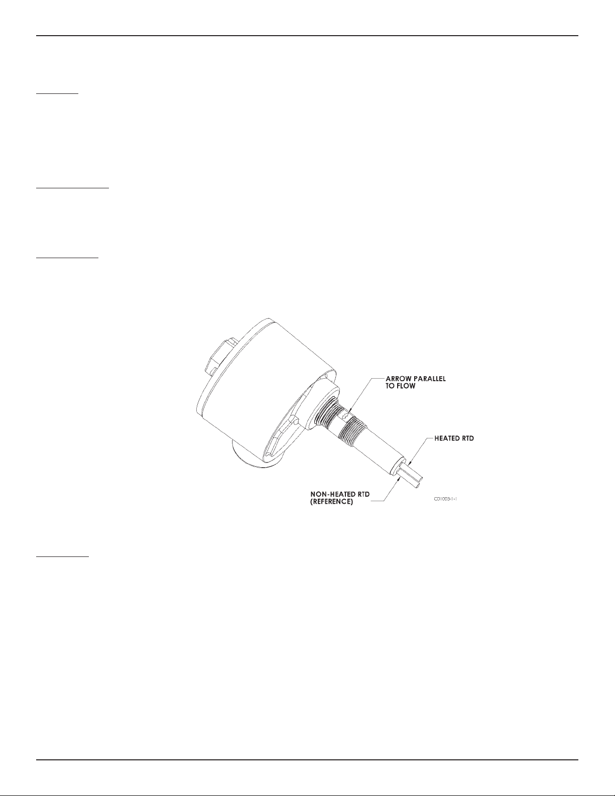
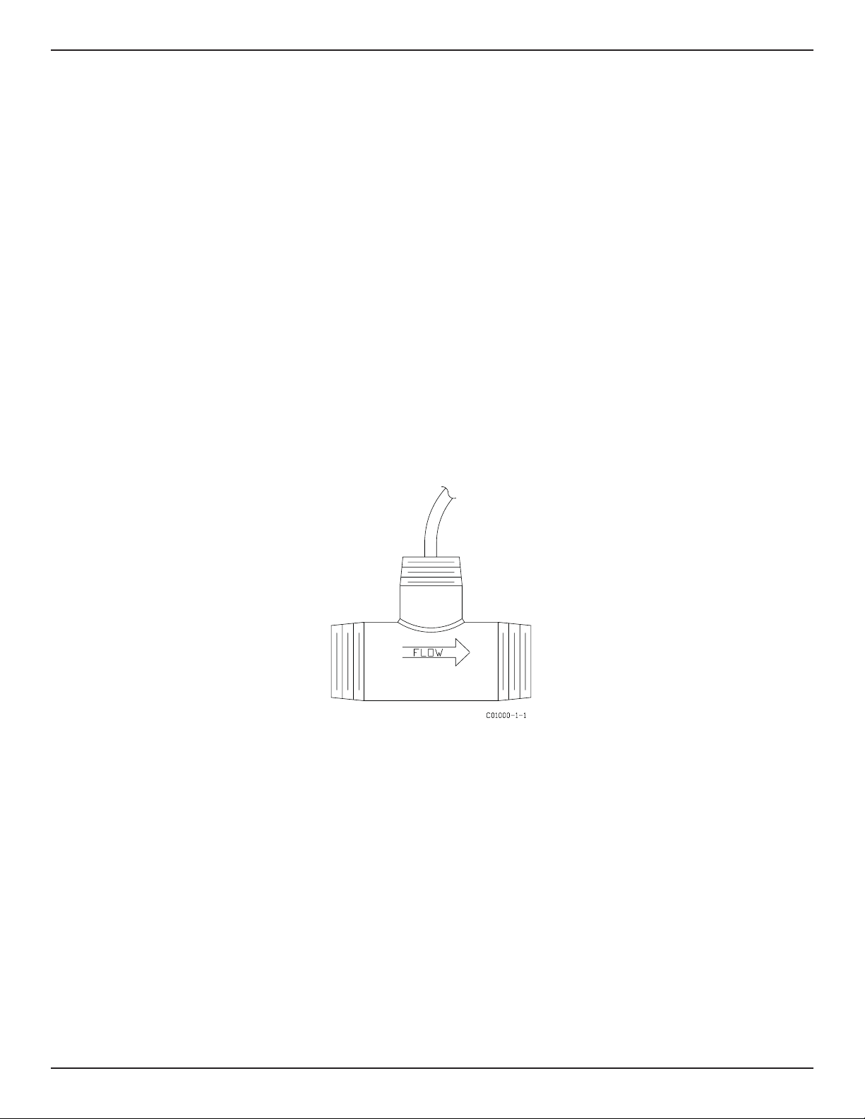
Sensing Element
The sensing element consists of two thermowells (hollow tubes) that when inserted into the fl ow process allows an unimpeded fl ow inside the
process line. The top thermowell has a self-heated RTD inserted into it. The bottom thermowell has a reference RTD inserted into it. In order to
correctly orient the sensing element a fl ow arrow has been etched onto the threaded portion of the sensing element. See Figure 1-1 for a view of the
sensing element.
Control Circuit
The control circuit converts the sensing element’s RTD temperature differential into an analog DC voltage signal. Dual comparators monitor the
sensing element signal and activates the relay alarm circuits if the signal exceeds an adjustable set point.
The control circuit contains fi eld removable jumpers that confi gures the instrument to perform in the fi eld as needed by the customer.
Figure 1-1 View of the Sensing Element

TECHNICAL SPECIFICATIONS FLT
®
Series FlexSwitch
TM
8 Fluid Components International LLC
Application
Flow rate and /or level /interface and temperature sensing in liquid,
gas and slurry applications.
Sensing Elements
Process Connection
Models S and F
3/4 inch male NPT standard; optional 1 inch BSP, 1 inch male
NPT, 3/4 inch Male NPT (FLT93-F only); fl anges, or spool pieces.
Model L
1” male NPT or 3/4” female NPT, both ends with orifi ce;
fl anges optional.
Insertion Length
Models S and F
Available in standard lengths of 1.2” [30mm], 2” [51mm],
4” [102mm], 6” [152mm], 9” [229mm], 12” [305mm],
18” [457mm] and custom-specifi ed lengths.
Model L
3.375” [86mm] in-line body length
Sensing Element
Models S and F
All wetted surfaces are 316L stainless steel with all-welded
construction. Hastelloy C, Monel 400, electro-polished
stainless steel and titanium (FLT93-S only) are optionally
available.
Model L
All wetted surfaces are 316L stainless steel with all-welded
construction. Hastelloy C, Monel 400 and titanium are
optionally available.
Operating Temperature
Sensing Element:
All Models
Standard temperature confi guration:
-40°F to +350°F [-40°C to +177°C]
Medium temperature confi guration:
-100°F to +500°F [-73°C to +260°C]
Model S Only
High temperature confi guration:
-100°F to +850°F [-73°C to +454°C]
Control Circuit:
All Models
Ambient -40°F to +140°F [-40°C to + 60°C]
Operating Pressure
Models S, F and L
2350 psig [ 162 bar(g)] maximum at 500°F [260°C]
1450 psig [100 bar(g)] maximum at 850°F [454°C]
Control Circuit Features
Control Circuit
Standard: Plug-in, socket mounted with dual alarm/trip epoxy sealed
relays.
Optional: Rack-mount confi guration (card cage or enclosure not
included)
Output Signal
Analog DC voltage related to fl ow or level / interface signal and
proportional to temperature, standard.
Input Power
Field selected or pre-confi gured in the factory to 115 Vac (±15),
230 Vac (±30, 50 to 60 Hz), 24 Vdc (+4, -3) or 24 Vac (+2, -6);
100 Vac ±10 optionally available. LED indicates power on.
Power Consumption
AC units, 13 VA maximum; DC units, 7 watts maximum.
Heater Power
Field or factory selected to optimize switching performance and
rangeability and selectable for specifi c fl uid service requirements.
7 watts power consumption, 230 mA maximum.
Typical Service Sensing Element Power (W)
Gas or Air S-Style 0.75
F-Style 0.25
Liquids S-Style 3.0
The above typical service power selections are for reference
only. Depending on application requirements, surface temperature
rating requirements, and rangeability expectations, alternate power
selections may be recommended. Other intermediate power selec-
tions can be made. Consult installation manual for recommendations
in your service.
Relay Rating
Dual SPDT or single DPDT fi eld confi gurable 6 amp resistive at 115
Vac, 240 Vac or 24 Vdc; hermetically sealed relay confi gurations
optionally available.
Electrical Enclosure
Aluminum (epoxy coated) or optional stainless steel. Enclosures are
rated for hazardous location use (Class I and II, Division 1 and 2,
Group B, C, D, E, F and G; and EEx d IIC) and resists the effect of
weather and corrosion (NEMA and CSA Type 4X and equivalent to
IP66).
For Flow Service
Setpoint Range
Model S
Water-based Liquids:
0.01 FPS to 0.5 FPS [0.003 MPS to 1.52 MPS]with 0.75 watt heater;
0.01 FPS to 3.0 FPS [0.003 MPS to 0.9 MPS] with 3.0 watt heater.
Hydrocarbon-based Liquids:
0.01 FPS to 1.0 FPS [0.003 MPS to 0.3 MPS] with 0.75 watt heater;
0.01 FPS to 5.0 FPS with [0.003 MPS to 1.5 MPS] with 3.0 watt
heater.
Air/Gas:
0.25 SFPS to 120 SFPS [0.08 NMPS to 37 NMPS] with 0.75 watt
heater at standard conditions; 70°F [21.1°C], 14.7 psia [1.013
bar(g)].
Other Fluids: Contact the factory for approximate rangeability.
Model F
Air/Gas:
0.25 SFPS to 120 SFPS [0.08 NMPS to 37 NMPS] 0.75 watt heater
at standard conditions; 70°F [21.1°C], 14.7 psig [1.013 bar(g)].
Model L
Water-based Liquids: 0.015 cc/sec to 50 cc/sec
Hydrocarbon-based Liquids: 0.033 cc/sec to 110 cc/sec
Air/Gas: 0.6 cc/sec to 20,000 cc/sec
Technical Speci cation

FLT
®
Series FlexSwitch
TM
TECHNICAL SPECIFICATIONS
Fluid Components International LLC 9
Factory Calibrated Switch Point Accuracy
Any fl ow rate within the instrument fl ow range may be selected as a
setpoint alarm. A factory-calibrated setpoint adjustment may be
optimally preset with accuracy of ±2% of setpoint velocity over an
operating temperature range of ±50°F [±28°C].
Monitoring Accuracy
Based on a measured output voltage over the entire fl ow range, an
operating temperature range of ±50°F [±28°C], and an operating
pressure range of ±100 psig [±7 bar(g)]:
Liquids: ±5% reading or ±0.04 SFPS [±0.012 NMPS],
whichever is larger
Gases: ±5% reading or ±2 SFPS [±0.61 NMPS], whichever is larger
Repeatability
±0.5% reading
For Level/Interface Service
Accuracy
Model S
±0.25° [±6.4 mm]
Model F
±0.1° [±2.5 mm]
Repeatability
Model S
±0.125° [±3.2 mm]
Model F
±0.05° [±1.3 mm]
For Temperature Service
Accuracy
±2.0°F [±1°C] with fi eld setpoint adjustment. Monitoring accuracy
±3.5°F [±2°C] with standard curve fi t output voltage operation
across the selected instrument temperature range. Higher accuracy
available with factory calibrations.
Repeatability
±1.0°F [±0.6°C]
The above accuracy is based on liquid or slurry service and in
gas service with a minimum 1 SFPS [0.3 NMPS] velocity past the
sensing element or with the heater deactivated for temperature
sensing service only.
MTBF: 190 years
SIL: SIL-2 compliant, safe failure fraction (SFF) 82% to 84%
Factory Application-Speci c Set-up and
Setpoint Calibration
Standard instrument factory default setting, unless otherwise
selected at order entry, will be as follows:
• 115 Vac input power for all FM Approved units. 230 Vac for all
other agency approval units.
• Dual SPDT alarms set for:
• Alarm No. 1: Preset for fl ow or level and to de-energize with
decreasing conditions.
• Alarm No. 2: Preset to de-energize for increasing temperature at
10 °F [5 °C] below the maximum instrument process tempera-
ture.
• Heater power at 0.25 watt on Model F or 0.75 watt on Model S.
• Calibration switch set at “operate.”
Factory calibration including set-up for specifi c service, process
fl uid and alarm conditions optionally available. Contact factory for
fl uid handling capabilities.
Nuclear Safety Certi cation
FLT93 sensor elements were qualifi ed for harsh environment applica-
tions under the guidelines of iEEE-323, iEEE-344 and iEEE-382.
Radiation Exposure
Models S and F
2×10
8
rads
High Temperature
5×10
7
rads
Electronics Module [5294] qualifi ed for radiation harsh
5×10
5
rads
Seismic Level
Models S and F
3g ZPA’s
High Temperature
8g ZPA’s
Shipping Weight (approximate)
Integral: 8 lb [3.6 kg]
Remote: 13 lb [5.9 kg]

FLT
®
Series FlexSwitch
TM
10 Fluid Components International LLC
INTENTIONALLY LEFT BLANK
FLT
®
Series FlexSwitch
TM
INSTALLATION
Fluid Components International LLC 11
2 INSTALLATION
Receiving/Inspection
• Unpack carefully.
• Verify that all items in the packing list are received and are correct.
• Inspect all instruments for damage or contaminants prior to installation.
If the above three items are satisfactory, proceed with the installation. If not, then stop and contact a customer service representative.
Packing/Shipping/Returns
These issues are addressed in Appendix D — Customer Service.
Factory Calibration Note
The instrument is factory calibrated to the applications as specifi ed at the time of order. There is no need to perform any verifi cation or
calibration steps prior to installing and placing the instrument in service unless the application has been varied.
Pre-Installation Procedure
Warning: Only qualifi ed personnel should install this instrument. Install and follow safety procedures in accordance with the current
National Electrical Code. Ensure that power is off during installation. Any instances where power is applied to the instru-
ment will be noted in this manual. Where the instructions call for the use of electrical current, the operator assumes all
responsibility for conformance to safety standards and practices.
Caution: The instrument contains electrostatic discharge (ESD) sensitive devices. Use standard ESD precautions when handling the
control circuit. See below, for ESD details.
The instrument is not designed for weld-in-place applications. Never weld to a process connection or a structural support.
Damage resulting from moisture penetration of the control circuit or fl ow element enclosure is not covered by product warranty.
Use Standard ESD Precautions
Use standard ESD precautions when opening an instrument enclosure or handling the control circuit. FCI recommends the use of the follow-
ing precautions: Use a wrist band or heel strap with a 1 megohm resistor connected to ground. If the instrument is in a shop setting there
should be static conductive mats on the work table and fl oor with a 1 megohm resistor connected to ground. Connect the instrument to
ground. Apply antistatic agents to hand tools to be used on the instrument. Keep high static producing items away from the instrument such
as non-ESD approved plastic, tape and packing foam.
The above precautions are minimum requirements to be used. The complete use of ESD precautions can be found in the U.S. Department Of
Defense Handbook 263.
Prepare or Verify Sensing Element Location
Prepare the process pipe for installation, or inspect the already prepared location to ensure that the instrument will fi t into the system.
Review the requirement for the supply power and alarm circuit connections.
Verify Dimensions
Verify the instrument’s dimensions versus the process location to be sure of a correct fi t. Also see Appendix A for dimensions.
Verify Sensing Element Flow Direction and Placement Orientation (Flow Application)
For fl ow detection, the sensing element surface marked with direction arrows should be oriented parallel to the process fl ow. The fl ow can
be from either direction.
Mount the sensing element at least 20 diameters downstream and 10 diameters upstream from any bends or interference in the process pipe
or duct to achieve the greatest accuracy.
For liquid fl ow service, the sensing element should be located in the process pipe so that the thermowells are always completely wet.
When mounted in a tee or section of pipe larger than the normal process pipe, position in a vertical run of pipe with fl ow upward. This will
prevent air or gas bubbles from becoming trapped at the sensor assembly.
Vertical positioning with fl ow downward is only recommended for higher fl ow rate applications (consult FCI).
INSTALLATION FLT
®
Series FlexSwitch
TM
12 Fluid Components International LLC
Verify Sensing Element Flow Direction and Placement Orientation (Level Application)
If the sensing element is side-mounted on the process vessel, then the surface marked with direction arrows should be vertically oriented.
If the sensing element is top- or bottom-mounted on the process vessel, the orientation of the surface marked with direction arrows does not
matter.
Install the Sensing Element
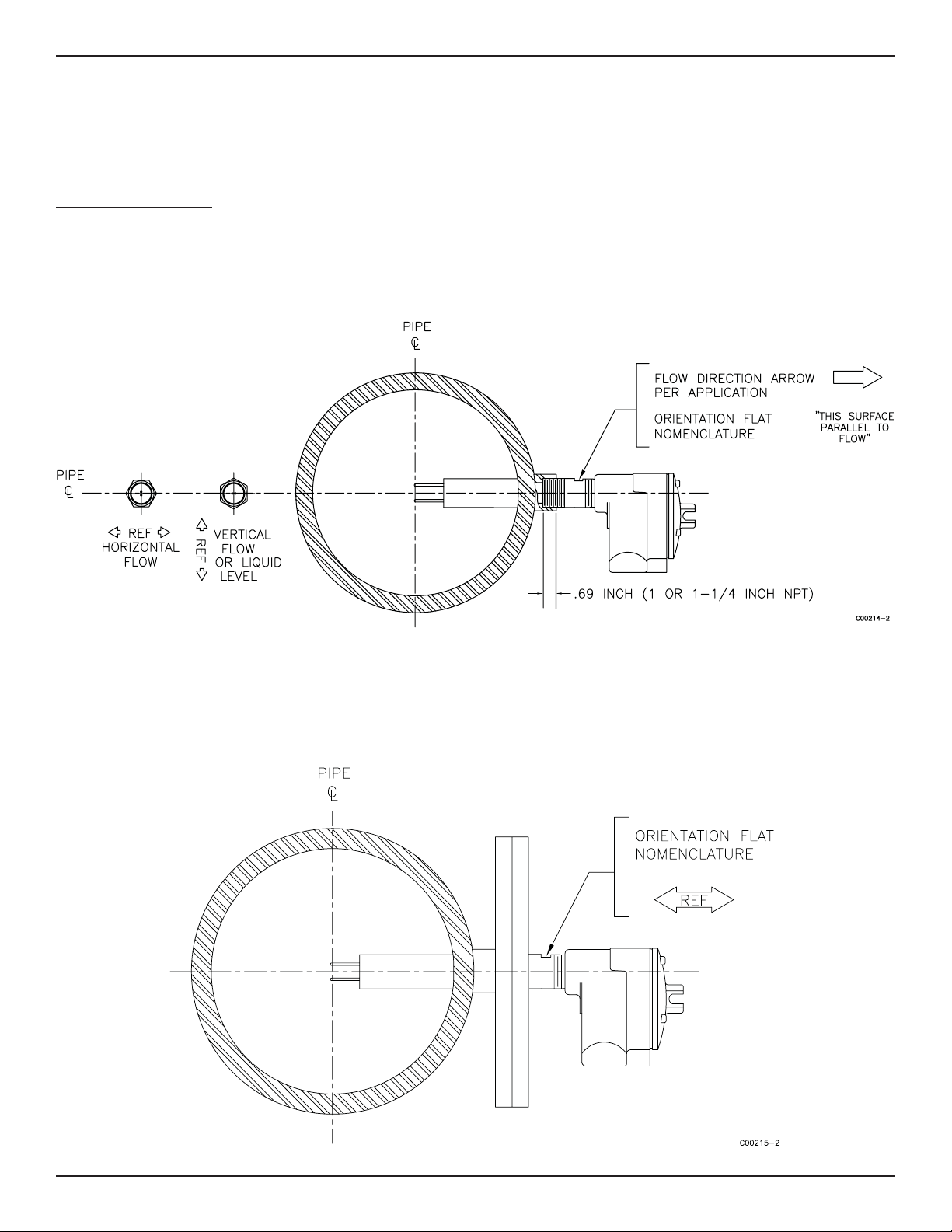
Male NPT Mounting
When mounting the sensing element to the process pipe, it is important that a lubricant/sealant be applied to the male threads of all con-
nections. Be sure to use a lubricant/sealant compatible with the process environment. All connections should be tightened fi rmly. To avoid
leaks, do not overtighten or cross-thread connections. See Figure 2-1 for proper mounting.
Figure 2-1 NPT Pipe Thread Mount
Flange Mounting
For fl ange mounted sensing elements, attach the process mating fl ange with care. The correct orientation of the sensing element must be
maintained to ensure optimum performance or calibration. See Figure 2-2.
Figure 2-2 Flange Mount
FLT
®
Series FlexSwitch
TM
INSTALLATION
Fluid Components International LLC 13
Packing Gland Assembly
1. Threaded or fl anged packing gland mounts are available. The valve assembly with appropriate connections are customer supplied. Fol-
low the male NPT mounting procedure above to attach the pipe thread portion or fl ange mounting portion as applicable.
2. Tighten the packing nut until the internal packing is tight enough so that the friction fi t on the shaft is adequate to prevent leakage but
not prevent the shaft from sliding. Position the etched fl ow arrow parallel with the fl ow (±1° of level) and position the fl ow arrow so it is
pointing in the direction of the fl ow.
3. Proceed to insert the probe into the process media line. Use the adjusting nuts on the all-thread to pull the sensing element into proper
predetermined depth position.
4. Tighten the opposing lock nuts on the all-threads. Tighten the packing nut another half to full turn until tight (approximately 65 to 85
ft-lbs [88 to 115 N-m] torque).
5. Rotate the split ring locking collar to line up with the connecting strap welded to the packing nut. Tighten the two 1/4-28 hex socket cap
screws on the split ring locking collar.
Reverse these steps for removal.
In-line NPT Assembly (FLT93-L)
The body length of the in-line assembly should be verifi ed to be sure the assembly will fi t into the process line. The direction of fl ow is im-
portant for proper operation. There is a fl ow direction arrow on the in-line pipe that is to point in the direction of fl ow. See Figure 2-3 for the
correct orientation.
If the instrument is a butt weld assembly, be sure to do the following: Remove the circuit board, properly ground the fl ow element before
welding, GTAW is highly recommended.
Figure 2-3 FLT93-L In-Line Flow Element
INSTALLATION FLT
®
Series FlexSwitch
TM
14 Fluid Components International LLC
Install and Wire the Enclosure(s)
Caution:
In applications where the sensing element is located in an explosive environment, isolate the conduit before it leaves the
environment. A potting Y may be used to provide the isolation.
Pulling wires can cause damage to the control circuit. Therefore, remove the control circuit from the enclosure and use
extreme care when pulling wires into the enclosure.
Mount and wire the control circuit either locally or remotely (option) by following the local or remote enclosure procedure below.
Minimum Wire Size
Table 2-1 shows the smallest (maximum AWG number) copper wire that is used in the electrical cables. Use a lower gauge of wire for less of
a voltage drop. Contact FCI concerning greater distances than those listed in the table. The sensing element cable must be shielded. If the
cable is spliced the shield wire must be continued through the splice. If a terminal block is used, the shield must have its own terminal.
Enclosures Covers
All enclosure covers must be in place and securely closed to achieve environmental and safety classifi cations.
All circular thread-on covers should be tightened about 1/3-turn past hand tight.
Cover locks must be in place and secure if required by a particular approval.
Note: Nitrile (buna-N) O-rings are standard on the circular thread covers;n these O-rings have a 250°F (121°C) maximum useage
temperature.
A Viton O-ring [400°F (204°C) max. temp.] is available for the thread-on covers; these O-rings have a 500°F (260°C) maximum useage tem-
perature.
To receive a Viton O-ring, provide FCI with the following information:
• Shipping address
• Quantity required
• Desired P/N:
Use P/N 000391-01 for the single conduit port enclosure (Local)
Cable and Conduit Entry Devices
The cable and conduit entry devices and blanking elements shall be of a certifi ed fl ameproof type EEx d, suitable for the conditions of use and
correctly installed. With the use of conduit entries a ceiling device shall be provided immediately on the entrance of the device.
All cable glands and conduit fi ttings, includign conduit plugs, must meet or exceed the area approval where the unit is being installed.
Connection
Maximum Distance for AWG
10 ft.
(3m)
50 ft
(15m)
100 ft.
(31m)
250 ft.
(76m)
500 ft.
(152m)
1000 ft.
(305m)
AC/DC Power 22 22 22 20 18 16
Relay (6A) 28 22 20 16 12 10
Flow Element Wires* 22 20 20 18 18 18
* Requires a shielded cable with the shield wire connected to the control socket only.
Table 2-1 Maximum AWG Number

FLT
®
Series FlexSwitch
TM
INSTALLATION
Fluid Components International LLC 15
Wiring the Local Enclosure
This procedure is for instruments with the control circuit located in the sensing element enclosure.
1. Remove the control circuit from its socket. Do not remove the control circuit socket. Removal of the control circuit socket may cause
damage to the instrument.
2. Install conduit between the local enclosure and the power source and monitoring circuit. Provide watertight hardware and apply thread
sealant to all connections to prevent water damage.
Warning:
Ensure that all power is off before wiring any circuit.
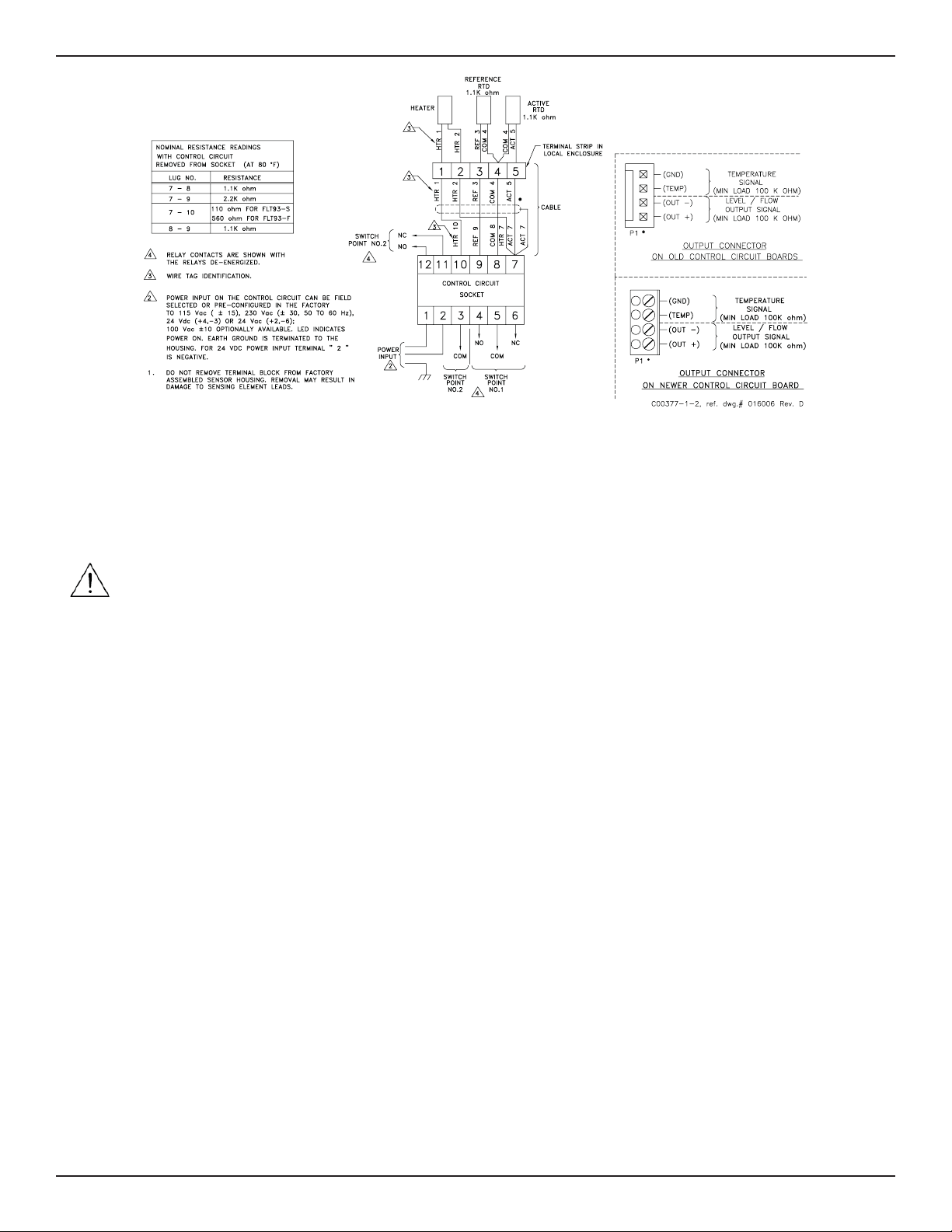
3. When connecting the relay wiring, do so with complete understanding of what the process requires of the instrument. The instrument
has dual SPDT or single DPDT relay output contacts dependent on the jumper confi guration for each alarm switch point. For the relay
logic, refer to Figure 2-5. Also refer to Table 3-5 and Table 3-6 in Chapter 3 — Operation. Relay contacts are shown with the relays de-
energized. Wire in accordance with the system requirements.
Figure 2-5 Local Wiring Diagram
Wiring the Remote Enclosure
This procedure is for instruments with the control circuit located remotely from the sensing element.
Locate the Remote Hardware Location
Select a location for the remote enclosure within a 1000 feet (305 m) of the sensing element. Pigtail sensing elements can not be located
more than 10 feet (3 m) from the enclosure unless the pigtail is extended with the proper size cable listed in Table 2-1. If the cable is ex-
tended the cable connections should be located in a junction box with a 6 position terminal block. All 5 conductors and the shield must have
its own termination. The remote enclosure should be easily accessible with enough room to open the enclosure cabinet cover at any time.
Secure the remote enclosure solidly to a vertical surface capable of providing support. Use appropriate hardware to secure the enclosure.
1. Remove the control circuit from the remote enclosure.
2. Run a fi ve-conductor, shielded cable from the local enclosure to the remote enclosure. Use Table 2-1 to determine which wire gauge to
use.
3. Wire between the local and remote enclosures according to Figure 2-6.
Warning: Ensure that all power is off before wiring any circuit.
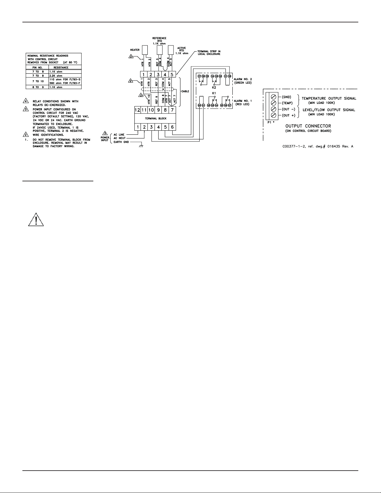
4. When connecting the relay wiring, do so with complete understanding of what the process requires of the instrument. The instrument
has dual SPDT or single DPDT relay output contacts dependent on the jumper confi guration for each alarm switch point. For the relay
logic, refer to Figure 2-6. Also refer to Table 3-5 and Table 3-6 in Chapter 3 — Operation. Relay contacts are shown with the relays de-
energized. Wire in accordance with the system requirements.
INSTALLATION FLT
®
Series FlexSwitch
TM
16 Fluid Components International LLC
relay board is in the same enclosure as the control circuit. Both boards are mounted on the same panel and have been wired together at the
factory. This confi guration can be ordered without an enclosure which can be supplied by the customer.
The alarm connections are made at the auxiliary relay board where each alarm is driving a DPDT relay.
Caution:
Do not connect any loads to the control circuit socket. Damage will occur to the control circuit if the alarm circuit is
energized.
Be sure the correct relay board has been ordered for the correct output. See the following paragraph.
This confi guration uses a control circuit that provides a switching voltage signal instead of relay contacts. The switch voltage is wired from
the control circuit socket to the auxiliary relay board actuating the relays.
The auxiliary relay board has several relay options that can be ordered. The options are as follows:
• Dry to 2 amps at 115 Vac or 28Vdc, Dry to 1 amp at 230 Vac (relay is enclosed in a plastic sealed cover).
• 100mA to 10mA at 115 Vac or 28Vdc, 50mA to 3 amps at 230 Vac (relay is enclosed in a plastic sealed cover).
• Dry to 0.5 amps at 115 Vac, hermetically sealed relay.
Make sure that the proper relays have been selected for the intended load. See Appendix A for the auxiliary relay board confi guration
drawing.
When connecting the relay wiring, do so with complete understanding of what the process requires of the instrument. The instrument has
dual DPDT or single 4PDT relay output contacts dependent on the jumper confi guration for each alarm switch point. For the relay logic, refer
to Figure 2-5. Also refer to Table 3-5 and Table 3-6 in Chapter 3 — Operation. Relay contacts are shown with the relays de-energized. Wire in
accordance with the system requirements.
The control circuit can be ordered with switching voltage outputs without ordering a relay board. This can be used with customer supplied
relays or any other device that has a differential input. The output voltage is 17 Vdc and will drive a load as low as 1500 ohms. Refer to
Figure 2-7 for the output terminals.
Wiring A Remote Control Circuit To An Auxiliary Relay Board
1. Run a four-conductor cable from the control circuit to the auxiliary relay board if the board was not factory installed. Use the wiring
diagram in Figure 2-7 to wire the boards together.
2. Attach the customer wiring as desired using Figure 2-7 as a wiring guide.
Wiring for this confi guration is the same as the sensing element wiring to the control circuit on a remote instrument.
Figure 2-6 Remote Wiring Diagram
FLT
®
Series FlexSwitch
TM
INSTALLATION
Fluid Components International LLC 17
Wiring Output Signal Terminals
Two output signals are provided on the control circuit at P1. The signal voltage at positions 1 and 2 represents the process change. The
signal voltage at positions 3 and 4 is proportional to the temperature at the sensing element. See Figures 2-5 through 2-7. See also Chapter
3 for the physical layout of the control circuit.
Caution: Do not ground terminal 2 of P1. (Terminal 2 is the negative lead of the process signal.) This terminal is 9 volts above the
control circuit ground. The peripheral using this signal must have a differential input.
These voltages can be used by other peripherals with a minimum load of 100K ohms. The terminal block can be wired with between gauge
26 and 18 wire (22 gauge wire is normally used). The maximum recommended length of wire is 1000 feet. Shielding is required on any
length of cable. The shield must be terminated at position 4 on P1.
Early versions of the FLT93 require a connecting harness that was supplied with each instrument. The harness can be ordered if it is missing.
The FCI part number is 015664-01. Newer versions of the FLT93 require a supplied terminal plug.
Figure 2-7 Auxilliary Relay Board Wiring Diagram

INSTALLATION FLT
®
Series FlexSwitch
TM
18 Fluid Components International LLC
INTENTIONALLY LEFT BLANK
 Loading…
Тепловое реле протока / вставки — FLT93S серии
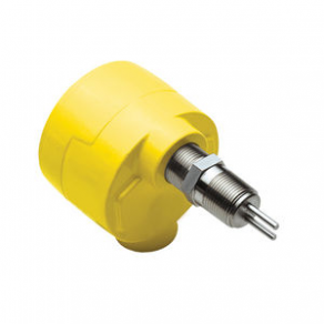

В FTL93S производится компанией Флюидных компонентов Международный ООО. Это вставки типа реле протока, которые могут быть использованы в широком спектре приложений, включая насос защиты, безопасности форсунка мониторинга, охлаждения воды/тепла бирж, нефтяная скважина тестирования системы, дренажной линии потока, и клапан сброса мониторинга.
В FLT93S может быть просто поле-настроен или на заводе, обеспечивая хороший уровень универсальности, точности и стабильности для всех многократный процесс зондирования и переключение требования.
Уставка диапазон для жидкости на основе воды составляет 0,01 до 3,0 кадров в секунду, для углеводородов на основе жидкости составляет 0,01 до 5,0 кадров в секунду , и для воздуха/газа от 0,25 до 120 модулей SFP.
Есть вопросы?
Вы можете задать их менеджерам наших партнеров прямо сейчас!
Задать вопрос
Note for Owners:
Guidesimo.com webproject is not a service center of FCI trademark and does not carries out works for diagnosis and repair of faulty FCI FLT93 Series equipment. For quality services, please contact an official service center of FCI company. On our website you can read and download documentation for your FCI FLT93 Series device for free and familiarize yourself with the technical specifications of device.
More Switch Devices:
-
ATZ HDMI-V2-44B
pg. 1 All specifications are subject to change without prior notice. © Copyright ATZ 2015 Model : ATZ HDMI-V2-44B Description: 4×4 HDMI2.0 Matrix Switch 18Gbps [email protected] (4:4:4) 1. Introduction T …
HDMI-V2-44B Switch, 12
-
Kramer VP-427UHD
VP-427UHD Quick Start P/N: 2900- 30115 6 QS Rev: 5 Scan for full manual VP-427UHD Quick Start Guide This guide helps you install and use your VP-427UHD for the first time. Go to www.kramerav.com/downloads/VP-427UHD to download the latest user manual and check if firmware upgrades are available. Step 1: Check what’s in the box VP-427UHD HDMI/HDBT Receiver/Switcher/Scaler 1 Bracket set 1 Q …
VP-427UHD Switch, 2
-
Black Box KV9628A
BL A C K B O X®This eight-port KVM switch provides the ultimate in multimedia and USB switching.ServSwitch™ DT Dual-Head DVI USB, 8-PortOrder toll-free in the U.S.: Call 877-877-BBOX (outside U.S. call 724-746-5500)FREE technical support 24 hours a day, 7 days a week: Call 724-746-5500 or fax 724-746-0746 • Mailing address: Black Box Corporation, 1000 Park Drive, Lawrence, PA 15055-1018 …
KV9628A Switch, 32
-
GSD GSDs-1FP
“Wireless NetworkSystem”GSD Wi-Enterprise/Wi-Plus System is thenext generation in access control solutions.It provides a Wireless Network throughoutthe premises, giving the convenience andsecurity of a fully networked system for afraction of the cost.For more information on the Wireless Network System visit our website www.globalsecurity.ieNo.1 Turnpike Business Park,Ballymount,Dublin 22, Irel …
GSDs-1FP Switch, 8
-
Davin DV‑44
Handleiding DV‑4431.0 ALGEMEENDe DV-44 is een tijdgestuurde relais kast waarmee maximaal 16 x 600 watt, óf 20 x 400 watt armaturen geschakeld kunnen worden.1.1 TECHNISCHE GEGEVENSAfmetingen : 210 x 290 x 90mm.Benodigde werkspanning : 230 Vac / 50Hz.Max. vermogen : 4 x 15 Ampère.Isolatie niveau : IP-441.2 BENODIGDE WERK SPANNING DV44Om de DV-44 aan te sluiten, heeft U vier ‘sch …
DV‑44 Switch, 12