- Manuals
- Brands
- Fluke Manuals
- Multimeter
- 8808A
- User manual
-
Contents
-
Table of Contents
-
Bookmarks
Quick Links
July 2007, Rev. 1, 12/09
© 2007, 2009 Fluke Corporation, All rights reserved. Specifications subject to change without notice.
All product names are trademarks of their respective companies.
8808A
Digital Multimeter
Users Manual
®
Related Manuals for Fluke 8808A
Summary of Contents for Fluke 8808A
-
Page 1: Digital Multimeter
® 8808A Digital Multimeter Users Manual July 2007, Rev. 1, 12/09 © 2007, 2009 Fluke Corporation, All rights reserved. Specifications subject to change without notice. All product names are trademarks of their respective companies.
-
Page 2
Fluke authorized resellers shall extend this warranty on new and unused products to end-user customers only but have no authority to extend a greater or different warranty on behalf of Fluke. Warranty support is available only if product is purchased through a Fluke authorized sales outlet or Buyer has paid the applicable international price. -
Page 3: Table Of Contents
Resistance …………………. 1-11 DC Current ………………..1-11 AC Current ………………..1-12 Frequency …………………. 1-13 Continuity …………………. 1-13 Diode Test ………………… 1-13 Preparing the Meter for Operation …………. 2-1 Introduction………………….2-3 Unpacking and Inspecting the Meter …………..2-3 Contacting Fluke………………..2-3…
-
Page 4
Turning Power On ………………… 2-8 Adjusting the Bail ………………..2-8 Installing the Meter into an Equipment Rack ………… 2-8 Cleaning the Meter………………… 2-9 Fluke 45 Emulation……………….. 2-9 Illuminating All Display Segments…………..2-10 Operating the Meter from the Front Panel ……..3-1 Introduction………………….3-3 Dual Display …………………. -
Page 5
(continued) Contents Local and Remote Operations …………… 4-3 Computer Interfaces ………………4-3 Preparing the Meter for Operations via the RS-232 Interface ……4-3 Setting Communication Parameters (RS-232) ……….4-3 RS-232 Print-Only Mode …………….4-4 Cabling the Meter to a Host or Printer (RS-232)……….. 4-5 Character Echoing and Deletion………….. -
Page 6
8808A Users Manual… -
Page 7
Safety and Electrical Symbols…………….1-6 1-3. Accessories………………….1-7 2-1. Line Voltage to Fuse Rating………………. 2-4 2-2. Line-Power Cord Types Available from Fluke…………2-7 3-1. Front-Panel Features ………………..3-4 3-2. Display Annunciators and Indicators …………..3-7 3-3. Rear-Panel Features ………………..3-8 3-4. -
Page 8
8808A Users Manual… -
Page 9
Title Page 2-1. Replacing the Line Power Fuse…………….2-5 2-2. Replacing the Current-Input Fuses…………….. 2-6 2-3. Line-Power Cord Types Available from Fluke…………2-7 2-4. Bail Adjustment and Removal …………….2-8 2-5. Boot Removal………………….2-9 3-1. Front Panel ………………….3-4 3-2. -
Page 10
8808A Users Manual viii… -
Page 11: Introduction And Specifications
Chapter 1 Introduction and Specifications Title Page Introduction………………….1-3 Manual Set ………………….1-3 About this Manual ………………..1-4 Safety Information ………………..1-4 General Safety Summary…………….. 1-4 Symbols ………………….1-6 Options and Accessories ………………1-7 General Specifications ………………1-8 Voltage ………………….1-8 Dimensions ………………….
-
Page 12
8808A Users Manual… -
Page 13: Introduction
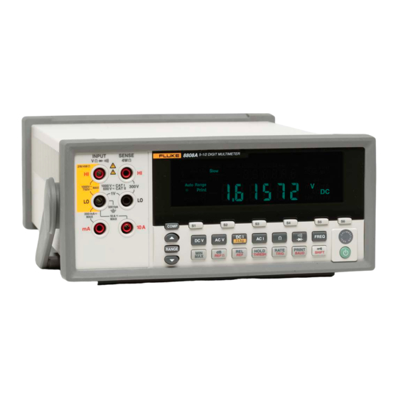
Introduction and Specifications Introduction Introduction The Fluke 8808A Digital Multimeter (hereafter referred to as the Meter) is a 5-1/2 digit dual-display multimeter designed for bench-top, field service, and system applications. The multiple measurement functions, plus the RS-232 remote interface, make the Meter an ideal candidate for precision manual measurements and use in automated systems.
-
Page 14: About This Manual
8808A Users Manual About this Manual This manual contains all the information a new user will need to operate the Meter effectively. This manual is divided into the following chapters: Chapter 1, “Introduction and Specifications,” provides information on how safely to use the Meter, and standard and optional accessories and specifications.
-
Page 15
Introduction and Specifications Safety Information Table 1-1. Safety Information XW Warning To avoid possible electric shock, personal injury, or death, read the following before using the Meter: Use the Meter only as specified in this manual, or the protection provided by the Meter might be impaired. -
Page 16: Symbols
Recycle Do not dispose of this product as Static awareness. Static discharge unsorted municipal waste. Contact can damage parts. Fluke or a qualified recycler for disposal. Measurement Category II is for Measurement Category I is for measurements performed on CAT II…
-
Page 17: Options And Accessories
Introduction and Specifications Options and Accessories Options and Accessories Table 1-3 lists available options and accessories. Table 1-3. Accessories Item Model / Part Number Premium Test Lead Set TL71 Fuse, .25*1.25, 0.063 A, 250 V, Slow 163030 Fuse, .25*1.25, 0.125 A, 250 V, Slow 166488 F1 — Fuse, 11 A, 1000 V, Fast, 406INX1.5IN, BULK 803293…
-
Page 18: General Specifications
8808A Users Manual General Specifications Voltage 100V Setting …………90 V to 110 V 120V Setting …………. 108 V to 132 V 220V Setting …………. 198 V to 242 V 240V Setting …………. 216 V to 264 V Frequency…………47 Hz to 440 Hz Power Consumption ………
-
Page 19: Remote Interfaces
Introduction and Specifications Electrical Specifications Overrange …………10 % on the largest ranges of all functions except continuity and diode test Remote Interfaces RS-232C Warranty One year Electrical Specifications Specifications are valid for 5-½ digit mode and after at least a half-hour warm-up. DC Voltage Specifications Maximum Input ……….
-
Page 20: Ac Voltage Specifications
8808A Users Manual AC Voltage Specifications AC Voltage specifications are for ac sinewave signals >5 % of range. For inputs from 1 % to 5 % of range and <50 kHz, add an additional error of 0.1 % of range, and for 50 kHz to 100 kHz, add 0.13 % of range. Maximum Input ……….
-
Page 21: Resistance
Introduction and Specifications Electrical Specifications Resistance Specifications are for 4-wire resistance function, or 2-wire resistance with REL. If REL is not used, add 0.2 for 2-wire resistance plus lead resistance. Measurement Method ……..Current source referenced to LO input Max Lead Resistance (4-wire ohms) ….10 % of range per lead for 200 , 2 k ranges. 1 k per lead on all other ranges.
-
Page 22: Ac Current
8808A Users Manual Accuracy Uncertainty Temperature Coefficient/ C Range 90 days 1 year Outside 18 – 28 C 23 C 23 C 200 A 0.02 + 0.005 0.03 + 0.005 0.003 + 0.001 2 mA 0.015 + 0.005 0.02 + 0.005 0.002 + 0.001 20 mA 0.03 + 0.02…
-
Page 23: Frequency
Introduction and Specifications Electrical Specifications Frequency Gate Time …………131 ms Measurement Method ……..AC-coupled input using the ac voltage measurement function. Settling Considerations ……..When measuring frequency after a dc offset voltage change, errors may occur. For the most accurate measurement, wait up to 1 second to allow input blocking RC time constant to settle.
-
Page 24
8808A Users Manual 1-14… -
Page 25: Preparing The Meter For Operation
Current-Input Fuses………………. 2-5 Connecting to Line Power …………….. 2-7 Turning Power On ………………… 2-8 Adjusting the Bail ………………..2-8 Installing the Meter into an Equipment Rack ………… 2-8 Cleaning the Meter………………… 2-9 Fluke 45 Emulation……………….. 2-9 Illuminating All Display Segments…………..2-10…
-
Page 26
8808A Users Manual… -
Page 27: Introduction
Fluke immediately. Save the container and packing material in case you have to return the Meter. Contacting Fluke To order accessories, receive operating assistance, or get the location of the nearest Fluke distributor or Service Center, call: USA:…
-
Page 28: Selecting The Line Voltage
8808A Users Manual Selecting the Line Voltage The Meter operates on four different input line voltages. The selected line-voltage setting is visible through the window in the line-fuse holder on the Meter’s rear panel. 1. Unplug the power cord. 2. Insert a small screwdriver blade into the narrow recess to the left of the fuse holder and pry it to the right until the holder pops out.
-
Page 29: Current-Input Fuses
Preparing the Meter for Operation Power Considerations eue20.eps Figure 2-1. Replacing the Line Power Fuse Current-Input Fuses The 200 mA and 10 A inputs are protected by user-replaceable fuses. The 200 mA input is protected by a fuse (F2) rated at 440 mA, 1000 V (fast blow), 10,000 A minimum breaking capacity.
-
Page 30
8808A Users Manual To replace the current-input fuses: 1. Remove power from the Meter by unplugging its power cord. 2. Turn the Meter upside down. 3. Remove the retaining screw on the fuse access door located on the bottom of the Meter. -
Page 31: Connecting To Line Power
2. Verify that the correct fuse for the line voltage is installed. 3. Connect the power cord to a properly grounded three-prong outlet. See Figure 2- 3 for line-power cord types available from Fluke. Refer to Table 2-2 for descriptions of the line-power cords.
-
Page 32: Turning Power On
8808A Users Manual Turning Power On 1. If required, connect the Meter to line power. 2. Toggle the power switch on the rear panel so the “I” side of the switch is depressed. The Meter will turn on and briefly illuminate all LCD segments. Note To save on power consumption, the Meter can be set to a standby mode by pressing P on the front panel.
-
Page 33: Cleaning The Meter
Do not use aromatic hydrocarbons, alcohol, chlorinated solvents, or methanol-based fluids when wiping down the Meter. Fluke 45 Emulation To switch the Meter to Fluke 45 emulation: Press and hold S and f for two seconds.
-
Page 34: Illuminating All Display Segments
8808A Users Manual Press U or V to scroll between F8808A and F45. The presently selected mode will appear bright in the display, while the other is dim. Press R to set the mode and reset the Meter. Illuminating All Display Segments To illuminate all display segments, start with the Meter display off.
-
Page 35: Operating The Meter From The Front Panel
Chapter 3 Operating the Meter from the Front Panel Title Page Introduction………………….3-3 Dual Display …………………. 3-6 Primary Display………………… 3-6 Secondary Display………………3-6 Rear Panel ………………….3-8 Adjusting Meter Range ………………3-8 Selecting a Measurement Rate…………….3-9 Selecting a Measurement Function…………..3-9 Measuring Voltage ………………
-
Page 36
8808A Users Manual… -
Page 37: Introduction
Operating the Meter from the Front Panel Introduction Introduction The Meter can be controlled either by sending commands through its RS232 communication interface or through the front panel. This chapter explains the function and use of the controls and indicators located on the front panel of the Meter. Operating the Meter through its RS232 communication interface is covered in Chapter 4.
-
Page 38
8808A Users Manual 8808A 5-1/2 DIGIT MULTIMETER INPUT SENSE 2W/4W 1000 V CAT I 1000V 300V 600 V CAT II 750V 500 V pk 200 mA 10 A eue02.eps Figure 3-1. Front Panel Table 3-1. Front-Panel Features Name Description INPUT VZYR HI, LO Input terminals for Volts, 2-Wire and 4-Wire Ohms, and Hz measurements. -
Page 39
Operating the Meter from the Front Panel Introduction Table 3-1. Front-Panel Features (cont.) Name Description Primary operation: Sets the Meter’s measurement rate to slow, medium or fast Second level operation: Selects source for triggering measurement Primary operation: Selects Touch Hold function Second level operation: Sets Touch Hold minimum response level Primary operation: Selects relative readings function to display… -
Page 40: Dual Display
8808A Users Manual Dual Display The Meter has a 5-1/2 digit vacuum fluorescent dual display. See Figure 3-2 and Table 3- 2 for an overview of the display annunciators and indicators The dual display is comprised of a primary display and a secondary display, which show measurement readings, annunciators and messages.
-
Page 41
Operating the Meter from the Front Panel Table 3-2. Display Annunciators and Indicators Name Description Meter is in remote mode (remotely controlled) the front panel is locked out Ext Trig Meter is in external trigger mode is pressed and secondary function will be selected Relative readings function modifier is selected –… -
Page 42: Rear Panel
8808A Users Manual Rear Panel See Figure 3-3 and Table 3-3 for an overview of the rear-panel features. eue03.eps Figure 3-3. Rear Panel Table 3-3. Rear-Panel Features Name Description Line power terminal Connects Meter to power source via power cord Power switch Turns power on and off to the Meter Fuse holder and power line voltage…
-
Page 43: Selecting A Measurement Rate
Operating the Meter from the Front Panel Selecting a Measurement Rate In autoranging mode, the Meter automatically selects the next higher range when a reading is greater than full-scale. If no higher range is available, 0L is displayed on the primary or secondary display to indicate an overload.
-
Page 44: Measuring Voltage
8808A Users Manual Measuring Voltage The Meter is capable of measuring voltage up to 1000 V dc and 750 V ac. W Caution To avoid possible damage to the Meter, do not apply voltage to the Meter’s inputs until the test leads are properly connected and the proper voltage function is selected.
-
Page 45: Frequency Ranging
Operating the Meter from the Front Panel Selecting a Measurement Function Frequency Ranging Frequency measurements are automatically ranged so that a frequency measurement is always displayed with maximum resolution. To select a range manually, press F to select the frequency function, and then press U or V to select a range manually.
-
Page 46: 4-Wire Resistance Measurement
10 A eue12.eps Figure 3-6. 4-Wire Resistance Measurement To make a four-wire resistance measurement using Fluke’s 2X4 test leads: 1. Connect the test leads to the Meter’s input connectors as show in Figure 3-7. 2. Press N. 2*4 Wire is displayed.
-
Page 47: Measuring Current
Operating the Meter from the Front Panel Selecting a Measurement Function INPUT SENSE 2W/4W 1000 V CAT I 1000V 300V 600 V CAT II 750V 500 V pk 200 mA 10 A Ground tab eue26.eps Figure 3-7. Input Connections for 4-Wire Ohms Using 2×4 Wire Leads Measuring Current W Caution To avoid blowing the current fuse or damaging the Meter, do…
-
Page 48: Automatic Input Terminal Detection
8808A Users Manual I < 200 mA INPUT SENSE 2W/4W 1000 V CAT I 1000V 300V 750V 600 V CAT II 500 V pk 200 mA 10 A V AC eue13.eps Figure 3-8. Current Measurement <200 mA I > 200 mA INPUT SENSE I <…
-
Page 49: Diode / Continuity Testing
Operating the Meter from the Front Panel Selecting a Measurement Function Diode / Continuity Testing Press G to toggle between the continuity and diode test functions for the primary display. (These functions cannot be selected for the secondary display.) To perform a continuity test: 1.
-
Page 50: Making A Triggered Measurement
8808A Users Manual INPUT SENSE 2W/4W 1000 V CAT I 1000V 300V 600 V CAT II 750V 500 V pk 200 mA 10 A eue16.eps Figure 3-11. Diode Test Making a Triggered Measurement The Meter features a trigger function that allows you to select a measurement trigger source.
-
Page 51: Selecting A Function Modifier
Operating the Meter from the Front Panel Selecting a Function Modifier An external TTL signal on pin 9 will trigger a measurement cycle. Alternatively, pin 9 of the RS-232 interface can be connected to pin 1 through an external switch. See Figure 3- 12.
-
Page 52: Relative Readings Modifier (Rel)
8808A Users Manual After a function modifier is selected, pressing any function button turns off all modifiers, causes the secondary display to go blank, and returns unmodified readings to the primary display. Relative Readings Modifier (REL) The relative readings modifier displays the difference between the relative base and the input measurement.
-
Page 53: Touch Hold Function (Hold)
Operating the Meter from the Front Panel Selecting a Function Modifier Table 3-5. dBM Reference Impedances Impedance Impedance Impedance 8000 1200 1000 Voltage annunciator lit Audio power readings possible To access the reference impedance list, press Q then press W. The reference impedance currently selected is displayed, along with the «db»…
-
Page 54: Minimum / Maximum Modifier (Min Max)
8808A Users Manual Level 1 (5 % of range) Level 2 (7 % of range) Level 3 (8 % of range) To change the response level, press Q and I. The response level currently selected (1, 2, 3 or 4) appears on the primary display. Press U or V to step to the desired response level, then press R for two seconds to set the level and return to the primary display.
-
Page 55: Using The Function Modifiers In Combination
Operating the Meter from the Front Panel Selecting a Function Modifier Using the Function Modifiers in Combination You can use multiple function modifiers simultaneously. Selected modifiers are evaluated in the following order: Touch Hold, minimum/maximum, and then relative readings. The Meter first looks for a stable measurement for Touch Hold, then determines if the measurement is a new minimum or maximum value, and then subtracts the relative base from the measurement.
-
Page 56: Compare Function (Comp)
8808A Users Manual Table 3-6. Second Level Operations (cont.) Buttons Description In COMP mode, stores value on primary display as LO compare point (see the “Using the Compare Function” section later in this manual) In COMP mode, stores value on primary display as HI compare point (see “Using the Compare Function”) [1] Hold both buttons for 2 seconds.
-
Page 57: Using The List Editor
Operating the Meter from the Front Panel List and Number Editors Using the List Editor The list editor is used to select the options described in Table 3-7. You may abort an edit and return to normal operation at any time by pressing Q. To use the list editor: 1.
-
Page 58: Using The Number Editor
8808A Users Manual Using the Number Editor Use the number editor to edit the relative base for the relative readings modifier and to set the high and low threshold values for the compare function. Note that you can abort the number editor and return the Meter to normal operation by pressing Q.
-
Page 59: Power-Up Configuration
Operating the Meter from the Front Panel Power-Up Configuration Range mode on primary display (manual or autorange) Measurement rate (slow, medium, fast) Dual display status (active or inactive) Any combination of selected function modifiers Touch Hold level (1, 2, 3, 4) Last recorded minimum and maximum values for MINMAX modifier Last recorded relative base Relative base shown in secondary display (enabled or disabled)
-
Page 60
8808A Users Manual 3-26… -
Page 61: Operating The Meter Using The Computer Interface
Chapter 4 Operating the Meter Using the Computer Interface Title Page Introduction………………….4-3 Local and Remote Operations …………… 4-3 Computer Interfaces ………………4-3 Preparing the Meter for Operations via the RS-232 Interface ……4-3 Setting Communication Parameters (RS-232) ……….4-3 RS-232 Print-Only Mode …………….
-
Page 62
8808A Users Manual Compare Commands and Queries …………..4-24 Trigger Configuration Commands…………..4-24 Miscellaneous Commands and Queries…………4-25 RS-232 Remote / Local Configurations …………4-25 RS-232 Save / Recall System Configurations ……….4-26 Sample Program Using the RS-232 Computer Interface ……..4-27… -
Page 63: Introduction
Operating the Meter Using the Computer Interface Introduction Introduction This chapter describes how to set up, configure and operate the Meter via the RS-232 computer interface on the Meter’s rear panel. The Meter can be operated from a host (a terminal, controller, PC, or computer) by sending commands to the Meter through its computer interface.
-
Page 64: Rs-232 Print-Only Mode
RS-232 Print-Only Mode The print-only mode is used to send measurements to a printer or terminal automatically. While the Meter will respond to remote commands during print-only operations, Fluke recommends first setting the Meter’s echo mode to OFF. This prevents mixing echoed command characters and incoming data.
-
Page 65: Cabling The Meter To A Host Or Printer (Rs-232)
Longer cables can be used if the load capacitance at the interface point (including signal terminator) is less than 2500 pf. To connect the Meter to a personal computer (with DB-9 connector), use a Fluke RS43 Null modem cable. Refer to Table 1-3.
-
Page 66: Character Echoing And Deletion
4. Type *IDN? and press Enter. 5. Verify that the Meter sends the following response: FLUKE, 8808A, nnnnnnn, n.n Dn.n Where nnnnnnn is the Meter’s serial number; n.n is the main software version; and Dn.n is the display’s software version.
-
Page 67: If Test Fails
Operating the Meter Using the Computer Interface How the Meter Processes Input If Test Fails If the Meter does not respond as indicated in the “Installation Test for RS-232 Operation” section, perform the following: 1. Ensure all cables are properly connected. See the “Cabling the Meter to a Host or Printer (RS-232)”…
-
Page 68: Sending Numeric Values To The Meter
8808A Users Manual Sending Numeric Values to the Meter Numeric values can be sent to the Meter as integers, real numbers, or real numbers with exponents, as shown in the following examples: +12345689 Sends the signed integer “12345689” -1.2345E2 Sends “-1.2345E2” or “-123.45” Sending Command Strings to the Meter Observe the following rules when you construct strings to be sent to the Meter over the computer interface:…
-
Page 69: Triggering Output
Operating the Meter Using the Computer Interface Triggering Output +/- 1.0E+9 Overload (0L on the display) Triggering Output The Meter takes measurements when triggered to do so. There are five trigger types, which are described in Table 4-3. Triggers fall into two basic categories: Internal trigger, which triggers measurements continuously.
-
Page 70: Setting The Trigger Type Configuration
8808A Users Manual Note In external trigger mode (mode 2 to mode 5), *TRG command is always available. Setting the Trigger Type Configuration To set the trigger type configuration using the computer interface, enter the command TRIGGER <type> (where <type> is the trigger type) and press Enter. See Table 4-3 for trigger types.
-
Page 71: Status Registers
Operating the Meter Using the Computer Interface Status Registers Status Registers The contents of the status register (STB) are determined by the service enable register (SRE), event status register (ESR), event status enable register (ESE), and the output buffer. These status registers are explained in the following paragraphs and summarized in Table 4-5.
-
Page 72: Event Status And Event Status Enable Registers
8808A Users Manual Standard Event Status Register Read Using *ESR? & & & & & & & Queue & Not-Empty Standard Event Status Enable Register Read Using *ESE? Write to Using *ESE Output Queue Read by Serial Poll Service Status Byte Register ESB MAV Request Generation…
-
Page 73
Operating the Meter Using the Computer Interface Status Registers When any enabled bit in the ESR changes from 0 to 1, the ESB bit in the STB also changes to 1. When the ESR is read using the *ESR? command or cleared using the *CLS command, the ESB bit in the STB returns to 0. -
Page 74: Status Byte Register
8808A Users Manual Table 4-6. Description of Bits in ESR and ESE Bit No. Name Condition Operation Complete (OPC) All commands before receipt of an *OPC command have been executed. Interface is ready to accept another message. Not used Always set to 0. Query Error (QYE) Attempted to read data from the Meter’s output buffer when no output was present or pending.
-
Page 75: Reading The Status Byte Register
Operating the Meter Using the Computer Interface Computer Interface Command Set Table 4-7. Description of Bits in the Status Byte Register (STB) (cont.) Bit No. Name Condition Master Summary Status (MSS) Set to 1 if any enabled bit in the STB (MSS) register is set to 1;…
-
Page 76: Common Commands
(1 or 0) of bits in the register. *IDN? Identification Query Meter returns the identification code of the Meter as four fields separated by commas. These fields are: Manufacturer (FLUKE); model (8808A); seven-digit serial number; and versions of main software and display software. *OPC Operation Complete…
-
Page 77: Function Commands And Queries
Operating the Meter Using the Computer Interface Computer Interface Command Set Table 4-8. Common Commands (cont.) Command Name Description *SRE Service Request Enable Sets the Service Request Enable Register to <value>, where <value> is an integer between 0 and 255. The value of bit 6 is ignored because the Service Request Enable Register does not use it.
-
Page 78
8808A Users Manual Table 4-9. Function Commands and Queries (cont.) Commands Function Primary Display Secondary Display FUNC1? (Not applicable) Meter returns function selected as command mnemonic. For example, if frequency is selected, FUNC1? returns FREQ. (Not applicable) FUNC2? Meter returns function selected as command mnemonic. -
Page 79: Function Modifier Commands And Queries
Operating the Meter Using the Computer Interface Computer Interface Command Set Function Modifier Commands and Queries Table 4-10 describes function modifier commands and queries. A function modifier causes the Meter to modify the normal operation of a measurement function or to perform an action on a measurement before displaying a reading.
-
Page 80
8808A Users Manual Table 4-10. Function Modifier Commands and Queries (cont.) Command Description HOLDTHRESH? Meter returns Touch Hold <threshold> (1, 2, 3, or 4). See “Touch Hold Function (HOLD)” in Chapter 3 for more information. Meter enters MAX modifier with present reading as maximum value. If already in MAX modifier, Meter displays maximum value. -
Page 81: Range And Measurement Rate Commands And Queries
Operating the Meter Using the Computer Interface Computer Interface Command Set Table 4-10. Function Modifier Commands and Queries (cont.) Command Description MOD? Meter returns a numeric value indicating modifiers in use, where 1 = MIN; 2 = MAX; 4 = HOLD; 8 = dB; 16 = dB Power; 32 = REL; and 64 = COMP. If multiple modifiers are selected, the value returned is equal to the sum of the values of the selected modifiers.
-
Page 82
8808A Users Manual Table 4-11. Range and Measurement Rate Commands and Queries (cont.) Command Description RANGE <value range> Sets the primary display to <value range> where <value range> is the number in the Range Value column of Table 4-11A that corresponds with the applicable function ranges (voltage, ohms, current, etc.). -
Page 83: Measurement Queries
Operating the Meter Using the Computer Interface Computer Interface Command Set Measurement Queries Table 4-12 describes measurement queries, which are shown on the primary and/or secondary displays. Table 4-12. Measurement Queries Command Description MEAS1? Meter returns the value shown on the primary display after the next triggered measurement is completed.
-
Page 84: Compare Commands And Queries
8808A Users Manual Compare Commands and Queries Table 4-13 describes the compare commands and queries. These commands cause the Meter to determine whether a measurement is higher than, lower than, or within a specified range. These commands correspond with C, U and V on the front panel.
-
Page 85: Miscellaneous Commands And Queries
Operating the Meter Using the Computer Interface Computer Interface Command Set Miscellaneous Commands and Queries Table 4-15 describes miscellaneous commands and queries. Table 4-15. Miscellaneous Commands and Queries Command Description ^C (CONTRL C) Causes =><CR><LF> to be output. FORMAT <format> Set output <format>…
-
Page 86: Rs-232 Save / Recall System Configurations
8808A Users Manual Table 4-17. Remote/Local Configuration Commands Command Description REMS Puts the Meter into remote (REMS) state mode without front panel lockout. r is shown on the display. RWLS Puts the Meter in remote with lockout state (RWLS) with front panel lockout. r and L are shown on the display.
-
Page 87: Sample Program Using The Rs-232 Computer Interface
Operating the Meter Using the Computer Interface Sample Program Using the RS-232 Computer Interface Sample Program Using the RS-232 Computer Interface Figure 4-4 is an annotated BASIC A program written for a PC that demonstrates how the Meter can be used with the RS-232 computer interface. aam23f.eps Figure 4-4.
-
Page 88
8808A Users Manual 4-28… -
Page 89: Appendices
Appendices Appendix Title Page Applications ………………….A-1 2X4 Test Leads ………………..B-1…
-
Page 90
8808A Users Manual… -
Page 91: Using The Dual Display
Appendix A Applications Introduction This chapter discusses some applications that will help you use the Meter effectively. These applications assume you are familiar with the basic operation of the Meter and have a basic understanding of electronics. A sophisticated understanding of electrical circuits is not necessary.
-
Page 92
8808A Users Manual eue25.eps Figure A-1. Example of Dual Display Showing Volts AC and Frequency Using Measurement Functions in Combination The dual display allows you to display select combinations of measurements for the input signal being measured. Allowable combinations of properties are shown in Table A-1. Volts (dc + ac) rms or current (dc + ac) rms measurements can only be made in the primary display. -
Page 93
Appendices Applications If the relative readings value of a dc voltage measurement is shown in the primary display and the dc voltage itself is shown in the secondary display, the Meter takes a single measurement and updates both displays with it. Updating Primary and Secondary Displays with Separate Measurements If the measurement function in the primary display is different from that in the secondary display, the Meter updates each display using a separate measurement. -
Page 94
8808A Users Manual Table A-2. Sample Dual Display Applications (cont.) Primary Secondary Applications Display Display Resistance Select and sort resistors. (See also «Using the Compare Function» in Chapter 3.) HOLD Actual Value Show actual measurement while holding a previous, stable measurement on the primary display 8808A 5-1/2 DIGIT MULTIMETER… -
Page 95
Appendices Applications function selected, number of measurements being made (single measurement when only the primary display is used, or two measurements when both the primary and secondary display are used), the input level, range type (autorange or manual range), the measurement rate (slow, medium, or fast), and whether measurement types are mixed or not. -
Page 96
8808A Users Manual Table A-3. Typical Single Measurement Response Times (in Seconds) Slow Rate Medium Rate Fast Rate Meas. Auto Single Auto Single Auto Single Function Range Range Range Range Range Range 0.05 0.05 0.05 0.05 0.10 0.72 0.18 0.56 0.14 Time to autorange a new measurement from the lowest to the highest range and to display the result. -
Page 97: External Trigger
Appendices Applications Table A-5. Typical Measurement Intervals (in Seconds) for Dual Display Measurements Meas. Range Slow Fast Function 0.85 0.85 External Trigger The external trigger can be used with or without settling delays, as shown in Table A-4. (Refer to Table 4-3 for trigger types.) The amount of trigger delay varies depending on differences between the primary and secondary displays, as described in the previous section.
-
Page 98
8808A Users Manual Making Low-Level Current Measurements There are many applications where obtaining the utmost accuracy in low-level current measurements is critical. For example, determining the leakage current of a battery operated device in its standby mode is critical in determining the time before battery re- charge is needed. -
Page 99
2X4 Test Leads Introduction The optional Fluke TL2X4W test leads simplify making 4-wire ohms measurements by integrating the Hi-Hi Sense and Lo-Lo Sense test leads into one cable. The Meter’s Input HI and LO jacks consist of two contacts. One contact is connected to HI or LO input circuits and the other contact is connected to the Sense input circuits. -
Page 100
8808A Users Manual…

PDF инструкция · 100 страниц(ы) английский
инструкцияFluke 8808A

®
8808A
Digital Multimeter
Users Manual
July 2007
© 2007 Fluke Corporation, All rights reserved.
All product names are trademarks of their respective companies.
Посмотреть инструкция для Fluke 8808A бесплатно. Руководство относится к категории мультиметры, 1 человек(а) дали ему среднюю оценку 8.7. Руководство доступно на следующих языках: английский. У вас есть вопрос о Fluke 8808A или вам нужна помощь? Задайте свой вопрос здесь
- 8808A Users Manual
- 1. Introduction and Specifications
- 2. Preparing the Meter for Operation
- 3. Operating the Meter from the Front Panel
- 4. Operating the Meter Using the Computer Interface
- Appendices
Главная
Технические характеристики
| Диапазон постоянного напряжения | 0.2 — 1000 V |
| Разрешение (постоянное напряжение) | 1 mV |
| Базовая точность (постоянное напряжение) | 0.015 + 0.003 |
| Диапазон переменного напряжения | 0.2 — 750 V |
| Разрешение (переменное напряжение) | 1 mV |
| Базовая точность (переменное напряжение) | 0.2 + 0.05 |
| Диапазон сопротивления | 200 — 100000000 Ω |
| Разрешение сопротивления | 0.001 Ω |
| Базовая точность (сопротивление) | 0.02 + 0.003 |
| Диапазон постоянного тока | 0.0002 — 10 A |
| Разрешение (постоянный ток) | 1 µA |
| Базовая точность (постоянный ток) | 0.02 + 0.005 |
| Диапазон переменного тока | 0.2 — 10 A |
| Разрешение (переменный ток) | 100 µA |
| Частотный диапазон | 0.2 — 2 kHz |
| Разрешение (частота) | 0.0001 Hz |
| Основная погрешность (частота) | 0.01% |
| Тип продукта | Цифровой мультиметр |
| Поддерживаемое размещение | Мультиметр для верстака |
| Цвет товара | Grey, White |
Вес и размеры
| Вес | 2100 g |
| Ширина | 217 mm |
| Глубина | 297 mm |
| Высота | 88 mm |
Экран
| Символы на дисплее | 5.5 символы |
показать больше
Не можете найти ответ на свой вопрос в руководстве? Вы можете найти ответ на свой вопрос ниже, в разделе часто задаваемых вопросов о Fluke 8808A.
Какая высота Fluke 8808A?
Какая ширина Fluke 8808A?
Какая толщина Fluke 8808A?
Инструкция Fluke 8808A доступно в русский?
Не нашли свой вопрос? Задайте свой вопрос здесь
- Manuals
- Brands
- Fluke Manuals
- Multimeter
- 8808A/SU
- User manual
-
Bookmarks
Quick Links
Test Equipment Depot — 800.517.8431 — 99 Washington Street Melrose, MA 02176 — TestEquipmentDepot.com
July 2007
© 2007 Fluke Corporation, All rights reserved.
All product names are trademarks of their respective companies.
8808A
Digital Multimeter
Users Manual
®
Related Manuals for Fluke 8808A/SU
Summary of Contents for Fluke 8808A/SU
-
Page 1
® Test Equipment Depot — 800.517.8431 — 99 Washington Street Melrose, MA 02176 — TestEquipmentDepot.com 8808A Digital Multimeter Users Manual July 2007 © 2007 Fluke Corporation, All rights reserved. All product names are trademarks of their respective companies. -
Page 2
Fluke authorized resellers shall extend this warranty on new and unused products to end-user customers only but have no authority to extend a greater or different warranty on behalf of Fluke. Warranty support is available only if product is purchased through a Fluke authorized sales outlet or Buyer has paid the applicable international price. -
Page 3
Resistance …………………. 1-11 DC Current ………………..1-11 AC Current ………………..1-12 Frequency …………………. 1-13 Continuity …………………. 1-13 Diode Test ………………… 1-13 Preparing the Meter for Operation …………. 2-1 Introduction………………….2-3 Unpacking and Inspecting the Meter …………..2-3 Contacting Fluke………………..2-3… -
Page 4
Turning Power On ………………… 2-8 Adjusting the Bail ………………..2-8 Installing the Meter into an Equipment Rack ………… 2-8 Cleaning the Meter………………… 2-9 Fluke 45 Emulation……………….. 2-9 Illuminating All Display Segments…………..2-10 Operating the Meter from the Front Panel ……..3-1 Introduction………………….3-3 Dual Display …………………. -
Page 5
(continued) Contents Introduction………………….4-3 Local and Remote Operations …………… 4-3 Computer Interfaces ………………4-3 Preparing the Meter for Operations via the RS-232 Interface ……4-3 Setting Communication Parameters (RS-232) ……….4-3 RS-232 Print-Only Mode …………….4-4 Cabling the Meter to a Host or Printer (RS-232)……….. 4-5 Character Echoing and Deletion………….. -
Page 6
8808A… -
Page 7
Safety and Electrical Symbols…………….1-6 1-3. Accessories………………….1-7 2-1. Line Voltage to Fuse Rating………………. 2-4 2-2. Line-Power Cord Types Available from Fluke…………2-7 3-1. Front-Panel Features ………………..3-4 3-2. Display Annunciators and Indicators …………..3-7 3-3. Rear-Panel Features ………………..3-8 3-4. -
Page 8
8808A A-4. Typical Settling Delays (in Seconds) …………..A-6 A-5. Typical Measurement Intervals (in seconds) for Dual Display Measurements ..A-7… -
Page 9
List of Figures 2-1. Replacing the Line Power Fuse…………….2-5 2-2. Replacing the Current-Input Fuses…………….. 2-6 2-3. Line-Power Cord Types Available from Fluke…………2-7 2-4. Bail Adjustment and Removal …………….2-8 2-5. Boot removal………………….2-9 3-1. Front Panel ………………….3-4 3-2. -
Page 10
8808A viii… -
Page 11
Chapter 1 Introduction and Specifications Title Page Introduction………………….1-3 Manual Set ………………….1-3 About this Manual ………………… 1-4 Safety Information ………………… 1-4 General Safety Summary…………….1-4 Symbols ………………….1-6 Options and Accessories ………………1-7 General Specifications ………………1-8 Voltage ………………….1-8 Dimensions ……………….. -
Page 12
8808A Users Manual… -
Page 13
Introduction and Specifications Introduction Introduction The Fluke 8808A Digital Multimeter (hereafter referred to as the Meter) is a 5-1/2 digit dual-display multimeter designed for bench-top, field service, and system applications. The multiple measurement functions, plus the RS-232 remote interface, make the Meter an ideal candidate for precision manual measurements and use in automated systems. -
Page 14
8808A Users Manual About this Manual This manual contains all the information a new user will need to operate the Meter effectively. This manual is divided into the following chapters: Chapter 1, “Introduction and Specifications,” provides information on how safely to use the Meter, and standard and optional accessories and specifications. -
Page 15
Introduction and Specifications Safety Information Table 1-1. Safety Information XW Warning To avoid possible electric shock, personal injury, or death, read the following before using the Meter: • Use the Meter only as specified in this manual, or the protection provided by the Meter might be impaired. -
Page 16
Recycle Do not dispose of this product as Static awareness. Static discharge unsorted municipal waste. Contact can damage parts. Fluke or a qualified recycler for disposal. Measurement Category II is for Measurement Category I is for measurements performed on CAT II… -
Page 17
Introduction and Specifications Options and Accessories Options and Accessories Table 1-3 lists available options and accessories. Table 1-3. Accessories Item Model / Part Number Premium Test Lead Set TL71 Fuse, .25*1.25, 0.063 A, 250 V, Slow 163030 Fuse, .25*1.25, 0.125 A, 250 V, Slow 166488 F1 — Fuse, 11 A, 1000 V, Fast, 406INX1.5IN, BULK 803293… -
Page 18
8808A Users Manual General Specifications Voltage 100V Setting …………90 V to 110 V 120V Setting …………. 108 V to 132 V 220V Setting …………. 198 V to 242 V 240V Setting …………. 216 V to 264 V Frequency…………47 Hz to 440 Hz Power Consumption ……… -
Page 19
Introduction and Specifications Electrical Specifications Electrical Input Protection ……….1000 V all ranges Overrange …………10 % on the largest ranges of all functions except continuity and diode test Remote Interfaces RS-232C Warranty One year Electrical Specifications Accuracy specifications are valid for 5-½ digit mode and after at least a half-hour warm-up DC Voltage Specifications Maximum Input ………. -
Page 20
8808A Users Manual AC Voltage Specifications AC Voltage specifications are for ac sinewave signals >5 % of range. For inputs from 1 % to 5 % of range and <50 kHz, add an additional error of 0.1 % of range, and for 50kHz to 100 kHz, add 0.13 % of range. Maximum Input ………. -
Page 21
Introduction and Specifications Electrical Specifications Resistance Specifications are for 4-wire resistance function, or 2-wire resistance with REL. If REL is not used, add 0.2 Ω for 2-wire resistance plus lead resistance. Measurement Method ……..Current source referenced to LO input Max Lead Resistance (4-wire ohms) …. -
Page 22
8808A Users Manual Accuracy Accuracy Temperature Coefficient/°C Range Outside 18 – 28 °C 90 days 1 year 23 °C ± 5 °C 23 °C ± 5 °C 200 μA 0.02 + 0.005 0.03 + 0.005 0.003 + 0.001 2 mA 0.015 + 0.005 0.02 + 0.005 0.002 + 0.001… -
Page 23
Introduction and Specifications Electrical Specifications Frequency Gate Time …………131 ms Measurement Method ……..AC-coupled input using the ac voltage measurement function. Settling Considerations ……..When measuring frequency after a dc offset voltage change, errors may occur. For the most accurate measurement, wait up to 1 second to allow input blocking RC time constant to settle. -
Page 24
8808A Users Manual 1-14… -
Page 25
Current-Input Fuses………………. 2-5 Connecting to Line Power …………….. 2-7 Turning Power On ………………… 2-8 Adjusting the Bail ………………..2-8 Installing the Meter into an Equipment Rack ………… 2-8 Cleaning the Meter………………… 2-9 Fluke 45 Emulation……………….. 2-9 Illuminating All Display Segments…………..2-10… -
Page 26
8808A Users Manual… -
Page 27
Carefully unpack the Meter from its shipping container and inspect the contents for damaged or missing items. If the Meter appears damaged or something is missing, contact the carrier and Fluke immediately. Save the container and packing material in case you have to return the Meter. -
Page 28
8808A Users Manual Selecting the Line Voltage The Meter operates on four different input line voltages. The selected line-voltage setting is visible through the window in the line-fuse holder on the Meter’s rear panel. 1. Unplug the power cord. 2. Insert a small screwdriver blade into the narrow recess to the left of the fuse holder and pry it to the right until the holder pops out. -
Page 29
Preparing the Meter for Operation Power Considerations eue20.eps Figure 2-1. Replacing the Line Power Fuse Current-Input Fuses The 200 mA and 10 A inputs are protected by user-replaceable fuses. • The 200 mA input is protected by a fuse (F2) rated at 440 mA, 1000 V (fast blow), 10,000 A minimum breaking capacity. -
Page 30
8808A Users Manual 1. Remove power from the Meter by unplugging its power cord. 2. Turn the Meter upside down. 3. Remove the retaining screw on the fuse access door located on the bottom of the Meter. See Figure 2-2. 4. -
Page 31
2. Verify that the correct fuse for the line voltage is installed. 3. Connect the power cord to a properly grounded three-prong outlet. See Figure 2- 3 for line-power cord types available from Fluke. Refer to Table 2-2 for descriptions of the line-power cords. -
Page 32
8808A Users Manual Turning Power On 1. If required, connect the Meter to line power. 2. Toggle the power switch on the rear panel so the “I” side of the switch is depressed. The Meter will turn on and briefly illuminate all LCD segments. Note To save on power consumption, the Meter can be set to a standby mode by pressing P on the front panel. -
Page 33
Do not use aromatic hydrocarbons, alchohol, chlorinated solvents, or methanol-based fluids when wiping down the Meter. Fluke 45 Emulation To switch the Meter to Fluke 45 emulation: Press and hold Sand f for two seconds. -
Page 34
8808A Users Manual Press Uor Vto scroll between F8808A and F45. The presently selected mode will appear bright in the display, while the other is dim. Press R to set the mode and reset the Meter. Illuminating All Display Segments To illimunate all display segments, start wth the Meter display off. -
Page 35
Chapter 3 Operating the Meter from the Front Panel Title Page Introduction………………….3-3 Dual Display …………………. 3-6 Primary Display………………… 3-6 Secondary Display………………3-6 Rear Panel ………………….3-8 Adjusting Meter Range ………………3-8 Selecting a Measurement Rate…………….3-9 Selecting a Measurement Function…………..3-9 Measuring Voltage ……………… -
Page 36
8808A Users Manual Calibration ………………….3-25… -
Page 37
Operating the Meter from the Front Panel Introduction Introduction The Meter can be controlled either by sending commands through its RS232 communication interface or through the front panel. This chapter explains the function and use of the controls and indicators located on the front panel of the Meter. Operating the Meter through its RS232 communication interface is covered in Chapter 4. -
Page 38
8808A Users Manual 8808A 5-1/2 DIGIT MULTIMETER INPUT SENSE 2W/4W 1000 V CAT I 1000V 300V 600 V CAT II 750V 500 V pk 200 mA 10 A eue02.eps Figure 3-1. Front Panel Table 3-1. Front-Panel Features Name Description INPUT VZYR HI, LO Input terminals for Volts, 2-Wire and 4-Wire Ohms, and Hz measurements. -
Page 39
Operating the Meter from the Front Panel Introduction Table 3-1. Front-Panel Features (cont.) Name Description Primary operation: Sets the Meter’s measurement rate to slow, medium or fast Second level operation: Selects source for triggering measurement Primary operation: Selects Touch Hold function Second level operation: Sets Touch Hold minimum response level Primary operation: Selects relative readings function to display… -
Page 40
8808A Users Manual Dual Display The Meter has a 5-1/2 digit vacuum fluorescent dual display. See Figure 3-2 and Table 3- 2 for an overview of the display annunciators and indicators The dual display is comprised of a primary display and a secondary display, which show measurement readings, annunciators and messages. -
Page 41
Operating the Meter from the Front Panel Dual Display Table 3-2. Display Annunciators and Indicators Name Description Meter is in remote mode (remotely controlled) the front panel is locked out Ext Trig Meter is in external trigger mode is pressed and secondary function will be selected Relative readings function modifier is selected Measurement value in secondary display is negative –… -
Page 42
8808A Users Manual Rear Panel See Figure 3-3 and Table 3-3 for an overview of the rear-panel features. eue03.eps Figure 3-3. Rear Panel Table 3-3. Rear-Panel Features Name Description Line power terminal Connects Meter to power source via power cord Power switch Turns power on and off to the Meter Fuse holder and power line voltage… -
Page 43
Operating the Meter from the Front Panel Selecting a Measurement Rate In autoranging mode, the Meter automatically selects the next higher range when a reading is greater than full-scale. If no higher range is available, 0L is displayed on the primary or secondary display to indicate an overload. -
Page 44
8808A Users Manual Measuring Voltage The Meter is capable of measuring voltage up to 1000 V dc and 750 V ac. W Caution To avoid possible damage to the Meter, do not apply voltage to the Meter’s inputs until the test leads are properly connected and the proper voltage function is selected. -
Page 45
Operating the Meter from the Front Panel Selecting a Measurement Function Frequency Ranging Frequency measurements are automatically ranged so that a frequency measurement is always displayed with maximum resolution. To select a range manually, press F to select the frequency function, and then press U or V to select a range manually. -
Page 46
10 A eue12.eps Figure 3-6. 4-Wire Resistance Measurement To make a four-wire resistance measurement using Fluke’s 2X4 test leads: 1. Connect the test leads to the Meter’s input connectors as show in Figure 3-7. 2. Press N. 2*4 Wire is displayed. -
Page 47
Operating the Meter from the Front Panel Selecting a Measurement Function INPUT SENSE 2W/4W 1000 V CAT I 1000V 300V 600 V CAT II 750V 500 V pk 200 mA 10 A Ground tab eue26.eps Figure 3-7. Input Connections for 4-Wire Ohms Using 2×4 Wire Leads Measuring Current W Caution To avoid blowing the current fuse or damaging the Meter, do… -
Page 48
8808A Users Manual I < 200 mA INPUT SENSE 2W/4W 1000 V CAT I 1000V 300V 750V 600 V CAT II 500 V pk 200 mA 10 A V AC eue13.eps Figure 3-8. Current Measurement <200 mA I > 200 mA INPUT SENSE I <… -
Page 49
Operating the Meter from the Front Panel Selecting a Measurement Function Diode / Continuity Testing Press G to toggle between the continuity and diode test functions for the primary display. (These functions cannot be selected for the secondary display.) To perform a continuity test: 1. -
Page 50
8808A Users Manual INPUT SENSE 2W/4W 1000 V CAT I 1000V 300V 600 V CAT II 750V 500 V pk 200 mA 10 A eue16.eps Figure 3-11. Diode Test Making a Triggered Measurement The Meter features a trigger function that allows you to select a measurement trigger source. -
Page 51
Operating the Meter from the Front Panel Selecting a Function Modifier An external TTL signal on pin 9 will trigger a measurement cycle. Alternatively, pin 9 of the RS-232 interface can be connected to pin 1 through an external switch. See Figure 3- 12. -
Page 52
8808A Users Manual After a function modifier is selected, pressing any function button turns off all modifiers, causes the secondary display to go blank, and returns unmodified readings to the primary display. Relative Readings Modifier (REL) The relative readings modifier displays the difference between the relative base and the input measurement. -
Page 53
Operating the Meter from the Front Panel Selecting a Function Modifier Table 3-5. dBM Reference Impedances Impedance Impedance Impedance 8000 Ω 300 Ω 93 Ω 1200 Ω 250 Ω 75 Ω 1000 Ω 150 Ω 50 Ω 900 Ω 135 Ω 16 Ω… -
Page 54
8808A Users Manual • Level 1 (0.01 % of reading) • Level 2 (0.1 % of reading) • Level 3 (1 % of reading) • Level 4 (10 % of reading) To change the response level, press Q and I. The response level currently selected (1, 2, 3 or 4) appears on the primary display. -
Page 55
Operating the Meter from the Front Panel Selecting a Function Modifier Using the Function Modifiers in Combination You can use multiple function modifiers simultaneously. Selected modifiers are evaluated in the following order: Touch Hold, minimum/maximum, and then relative readings. The Meter first looks for a stable measurement for Touch Hold, then determines if the measurement is a new minimum or maximum value, and then subtracts the relative base from the measurement. -
Page 56
8808A Users Manual Table 3-6. Second Level Operations (cont.) Buttons Description In COMP mode, stores value on primary display as LO compare point (see the “Using the Compare Function” section later in this manual) In COMP mode, stores value on primary display as HI compare point (see “Using the Compare Function”) [1] Hold both buttons for 2 seconds. -
Page 57
Operating the Meter from the Front Panel List and Number Editors Using the List Editor The list editor is used to select the options described in Table 3-7. You may abort an edit and return to normal operation at any time by pressing Q. To use the list editor: 1. -
Page 58
8808A Users Manual Using the Number Editor Use the number editor to edit the relative base for the relative readings modifier and to set the high and low threshold values for the compare function. Note that you can abort the number editor and return the Meter to normal operation by pressing Q. -
Page 59
Operating the Meter from the Front Panel Power-Up Configuration • Measurement function on secondary display • Range mode on primary display (manual or autorange) • Measurement rate (slow, medium, fast) • Dual display status (active or inactive) • Any combination of selected function modifiers •… -
Page 60
8808A Users Manual 3-26… -
Page 61
Chapter 4 Operating the Meter Using the Computer Interface Title Page Introduction………………….4-3 Local and Remote Operations …………… 4-3 Computer Interfaces ………………4-3 Preparing the Meter for Operations via the RS-232 Interface ……4-3 Setting Communication Parameters (RS-232) ……….4-3 RS-232 Print-Only Mode ……………. -
Page 62
8808A Users Manual Compare Commands and Queries …………..4-24 Trigger Configuration Commands…………..4-24 Miscellaneous Commands and Queries…………4-25 RS-232 Remote / Local Configurations …………4-25 RS-232 Save / Recall System Configurations ……….4-26 Sample Program Using the RS-232 Computer Interface ……..4-27… -
Page 63
Operating the Meter Using the Computer Interface Introduction Introduction This chapter describes how to set up, configure and operate the Meter via the RS-232 computer interface on the Meter’s rear panel. The Meter can be operated from a host (a terminal, controller, PC, or computer) by sending commands to the Meter through its computer interface. -
Page 64
RS-232 Print-Only Mode The print-only mode is used to send measurements to a printer or terminal automatically. While the Meter will respond to remote commands during print-only operations, Fluke recommends first setting the Meter’s echo mode to OFF. This prevents mixing echoed command characters and incoming data. -
Page 65
Longer cables can be used if the load capacitance at the interface point (including signal terminator) is less than 2500 pf. To connect the Meter to a personal computer (with DB-9 connector), use a Fluke RS41-3 Null modem cable. Refer to Table 1-3. -
Page 66
4. Type *IDN? and press Enter. 5. Verify that the Meter sends the following response: FLUKE, 8808A, nnnnnnn, n.n Dn.n Where nnnnnnn is the Meter’s serial number; n.n is the main software version; and Dn.n is the display’s software version. -
Page 67
Operating the Meter Using the Computer Interface How the Meter Processes Input 6. If the Meter does not respond as indicated, refer to the “If Test Fails” section. If Test Fails If the Meter does not respond as indicated in the “Installation Test for RS-232 Operation” section, perform the following: 1. -
Page 68
8808A Users Manual In some instances, a terminator is automatically transmitted at the end of the host’s output string (the Meter’s input string). Sending Numeric Values to the Meter Numeric values can be sent to the Meter as integers, real numbers, or real numbers with exponents, as shown in the following examples: +12345689 Sends the signed integer “12345689”… -
Page 69
Operating the Meter Using the Computer Interface Triggering Output +1.2345E+6(format 1) Measured value of 1.2345M +12.345E+6 OHM(format 2) Measured value of 12.345Mohms +/- 1.0E+9 Overload (0L on the display) Triggering Output The Meter takes measurements when triggered to do so. There are five trigger types, which are described in Table 4-3. -
Page 70
8808A Users Manual If you enter the remote mode with trigger type 4 or 5 selected, the Meter remains in its external trigger state; however, because the Meter is in the remote mode, you will only be able to trigger measurements with rear trigger types 4 and 5. To exit remote mode, perform steps 1 and 2 and select trigger type 2 or 3 (as applicable). -
Page 71
Operating the Meter Using the Computer Interface Status Registers Status Registers The contents of the status register (STB) are determined by the service enable register (SRE), event status register (ESR), event status enable register (ESE), and the output buffer. These status registers are explained in the following paragraphs and summarized in Table 4-5. -
Page 72
8808A Users Manual Standard Event Status Register Read Using *ESR? & & & & & & & Queue & Not-Empty Standard Event Status Enable Register Read Using *ESE? Write to Using *ESE Output Queue Read by Serial Poll Service Status Byte Register ESB MAV Request Generation… -
Page 73
Operating the Meter Using the Computer Interface Status Registers The ESE is a mask register that allows the host to enable or disable (mask) each bit in the ESR. When a bit in the ESE is set to 1, the corresponding bit in the ESR is enabled. When any enabled bit in the ESR changes from 0 to 1, the ESB bit in the STB also changes to 1. -
Page 74
8808A Users Manual Table 4-6. Description of Bits in ESR and ESE Bit No. Name Condition Operation Complete (OPC) All commands before receipt of an *OPC command have been executed. Interface is ready to accept another message. Not used Always set to 0. Query Error (QYE) Attempted to read data from the Meter’s output buffer when no output was present or pending. -
Page 75
Operating the Meter Using the Computer Interface Computer Interface Command Set Table 4-7. Description of Bits in the Status Byte Register (STB) (cont.) Bit No. Name Condition Master Summary Status (MSS) Set to 1 if any enabled bit in the STB (MSS) register is set to 1;… -
Page 76
(1 or 0) of bits in the register. *IDN? Identification Query Meter returns the identification code of the Meter as four fields separated by commas. These fields are: Manufacturer (FLUKE); model (8808A); seven-digit serial number; and versions of main software and display software. *OPC Operation Complete… -
Page 77
Operating the Meter Using the Computer Interface Computer Interface Command Set Table 4-8. Common Commands (cont.) Command Name Description *SRE Service Request Enable Sets the Service Request Enable Register to <value>, where <value> is an integer between 0 and 255. The value of bit 6 is ignored because the Service Request Enable Register does not use it. -
Page 78
8808A Users Manual Table 4-9. Function Commands and Queries (cont.) Commands Function Primary Display Secondary Display FUNC1? (Not applicable) Meter returns function selected as command mnemonic. For example, if frequency is selected, FUNC1? returns FREQ. (Not applicable) FUNC2? Meter returns function selected as command mnemonic. -
Page 79
Operating the Meter Using the Computer Interface Computer Interface Command Set Function Modifier Commands and Queries Table 4-10 describes function modifier commands and queries. A function modifier causes the Meter to modify the normal operation of a measurement function or to perform an action on a measurement before displaying a reading. -
Page 80
8808A Users Manual Table 4-10. Function Modifier Commands and Queries (cont.) Command Description HOLDTHRESH? Meter returns Touch Hold <threshold> (1, 2, 3, or 4). See “Touch Hold Function (HOLD)” in Chapter 3 for more information. Meter enters MAX modifier with present reading as maximum value. If already in MAX modifier, Meter displays maximum value. -
Page 81
Operating the Meter Using the Computer Interface Computer Interface Command Set Table 4-10. Function Modifier Commands and Queries (cont.) Command Description MOD? Meter returns a numeric value indicating modifiers in use, where 1 = MIN; 2 = MAX; 4 = HOLD; 8 = dB; 16 = dB Power; 32 = REL; and 64 = COMP. If multiple modifiers are selected, the value returned is equal to the sum of the values of the selected modifiers. -
Page 82
8808A Users Manual Table 4-11. Range and Measurement Rate Commands and Queries (cont.) Command Description RANGE <value range> Sets the primary display to <value range> where <value range> is the number in the Range Value column of Table 4-11A that corresponds with the applicable function ranges (voltage, ohms, current, etc.). -
Page 83
Operating the Meter Using the Computer Interface Computer Interface Command Set Measurement Queries Table 4-12 describes measurement queries, which are shown on the primary and/or secondary displays. Table 4-12. Measurement Queries Command Description MEAS1? Meter returns the value shown on the primary display after the next triggered measurement is completed. -
Page 84
8808A Users Manual Compare Commands and Queries Table 4-13 describes the compare commands and queries. These commands cause the Meter to determine whether a measurement is higher than, lower than, or within a specified range. These commands correspond with C, U and V on the front panel. -
Page 85
Operating the Meter Using the Computer Interface Computer Interface Command Set Miscellaneous Commands and Queries Table 4-15 describes miscellaneous commands and queries. Table 4-15. Miscellaneous Commands and Queries Command Description ^C (CONTRL C) Causes =><CR><LF> to be output. FORMAT <format> Set output <format>… -
Page 86
8808A Users Manual Table 4-17. Remote/Local Configuration Commands Command Description REMS Puts the Meter into remote (REMS) state mode without front panel lockout. r is shown on the display. RWLS Puts the Meter in remote with lockout state (RWLS) with front panel lockout. r and L are shown on the display. -
Page 87
Operating the Meter Using the Computer Interface Sample Program Using the RS-232 Computer Interface Sample Program Using the RS-232 Computer Interface Figure 4-4 is an annotated BASIC A program written for a PC that demonstrates how the Meter can be used with the RS-232 computer interface. aam23f.eps Figure 4-4. -
Page 88
8808A Users Manual 4-28… -
Page 89
Appendices Appendix Title Page Applications ………………….A-1 2X4 Test Leads ………………..B-1… -
Page 90
8808A Users Manual… -
Page 91
Appendix A Applications Introduction This chapter discusses some applications that will help you use the Meter effectively. These applications assume you are familiar with the basic operation of the Meter and have a basic understanding of electronics. A sophisticated understanding of electrical circuits is not necessary. -
Page 92
8808A Users Manual eue25.eps Figure A-1. Example of Dual Display Showing Volts AC and Frequency Using Measurement Functions in Combination The dual display allows you to display select combinations of measurements for the input signal being measured. Allowable combinations of properties are shown in Table A-1. Volts (dc + ac) rms or current (dc + ac) rms measurements can only be made in the primary display. -
Page 93
Appendices Applications If the relative readings value of a dc voltage measurement is shown in the primary display and the dc voltage itself is shown in the secondary display, the Meter takes a single measurement and updates both displays with it. Updating Primary and Secondary Displays with Separate Measurements If the measurement function in the primary display is different from that in the secondary display, the Meter updates each display using a separate measurement. -
Page 94
8808A Users Manual Table A-2. Sample Dual Display Applications (cont.) Primary Secondary Applications Display Display • Select and sort resistors. (See also «Using the Compare Function» Resistance in Chapter 3.) • Show actual measurement while holding a previous, stable HOLD Actual Value measurement on the primary display 8808A… -
Page 95
Appendices Applications Repsonse Times Response time is the time between a change in an input and when that change is displayed. The meter’s response time depends on many factors: the measurement function selected, number of measurements being made (single measurement when only the primary display is used, or two measurements when both the primary and secondary display are used), the input level, range type (autorange or manual range), the measurement rate (slow, medium, or fast), and whether measurement types are mixed or… -
Page 96
8808A Users Manual Table A-3. Typical Single Measurement Response Times (in Seconds) Slow Rate Medium Rate Fast Rate Meas. Auto Single Auto Single Auto Single Function Range Range Range Range Range Range 0.05 0.05 0.05 0.05 0.05 0.15 Time to autorange a new measurement from the lowest to the highest range and to display the result. Typical time to change to the next higher or lower range and display the result. -
Page 97
Appendices Applications Table A-5. Typical Measurement Intervals (in Seconds) for Dual Display Measurements Meas. Range Slow Fast Function 0.85 0.85 External Trigger The external trigger can be used with or without settling delays, as shown in Table A-4. (Refer to Table 4-3 for trigger types.) The amount of trigger delay varies depending on differences between the primary and secondary displays, as described in the previous section. -
Page 98
8808A Users Manual Making Low-Level Current Measurements There are many applications where obtaining the utmost accuracy in low-level current measurements is critical. For example, determining the leakage current of a battery operated device in its standby mode is critical in determining the time before battery re- charge is needed. -
Page 99
2X4 Test Leads Introduction The optional Fluke TL2X4W test leads simplify making 4-wire ohms measurements by integrating the Hi-Hi Sense and Lo-Lo Sense test leads into one cable. The Meter’s Input HI and LO jacks consist of two contacts. One contact is connected to HI or LO input circuits and the other contact is connected to the Sense input circuits. -
Page 100
8808A Users Manual…
This manual is also suitable for:
8808a
![]()
®
8808A
Digital Multimeter
Users Manual
July 2007
© 2007 Fluke Corporation, All rights reserved.
All product names are trademarks of their respective companies.
LIMITED WARRANTY AND LIMITATION OF LIABILITY
Each Fluke product is warranted to be free from defects in material and workmanship under normal use and service. The warranty period is one year and begins on the date of shipment. Parts, product repairs, and services are warranted for 90 days. This warranty extends only to the original buyer or end-user customer of a Fluke authorized reseller, and does not apply to fuses, disposable batteries, or to any product which, in Fluke’s opinion, has been misused, altered, neglected, contaminated, or damaged by accident or abnormal conditions of operation or handling. Fluke warrants that software will operate substantially in accordance with its functional specifications for 90 days and that it has been properly recorded on non-defective media. Fluke does not warrant that software will be error free or operate without interruption.
Fluke authorized resellers shall extend this warranty on new and unused products to end-user customers only but have no authority to extend a greater or different warranty on behalf of Fluke. Warranty support is available only if product is purchased through a Fluke authorized sales outlet or Buyer has paid the applicable international price. Fluke reserves the right to invoice Buyer for importation costs of repair/replacement parts when product purchased in one country is submitted for repair in another country.
Fluke’s warranty obligation is limited, at Fluke’s option, to refund of the purchase price, free of charge repair, or replacement of a defective product which is returned to a Fluke authorized service center within the warranty period.
To obtain warranty service, contact your nearest Fluke authorized service center to obtain return authorization information, then send the product to that service center, with a description of the difficulty, postage and insurance prepaid (FOB Destination). Fluke assumes no risk for damage in transit. Following warranty repair, the product will be returned to Buyer, transportation prepaid (FOB Destination). If Fluke determines that failure was caused by neglect, misuse, contamination, alteration, accident, or abnormal condition of operation or handling, including overvoltage failures caused by use outside the product’s specified rating, or normal wear and tear of mechanical components, Fluke will provide an estimate of repair costs and obtain authorization before commencing the work. Following repair, the product will be returned to the Buyer transportation prepaid and the Buyer will be billed for the repair and return transportation charges (FOB Shipping Point).
THIS WARRANTY IS BUYER’S SOLE AND EXCLUSIVE REMEDY AND IS IN LIEU OF ALL OTHER WARRANTIES, EXPRESS OR IMPLIED, INCLUDING BUT NOT LIMITED TO ANY IMPLIED WARRANTY OF MERCHANTABILITY OR FITNESS FOR A PARTICULAR PURPOSE. FLUKE SHALL NOT BE LIABLE FOR ANY SPECIAL, INDIRECT, INCIDENTAL, OR CONSEQUENTIAL DAMAGES OR LOSSES, INCLUDING LOSS OF DATA, ARISING FROM ANY CAUSE OR THEORY.
Since some countries or states do not allow limitation of the term of an implied warranty, or exclusion or limitation of incidental or consequential damages, the limitations and exclusions of this warranty may not apply to every buyer. If any provision of this Warranty is held invalid or unenforceable by a court or other decision-maker of competent jurisdiction, such holding will not affect the validity or enforceability of any other provision.
|
Fluke Corporation |
Fluke Europe B.V. |
|
P.O. Box 9090 |
P.O. Box 1186 |
|
Everett, WA 98206-9090 |
5602 BD Eindhoven |
|
U.S.A. |
The Netherlands |
11/99
To register your product online, visit register.fluke.com
Table of Contents
|
Chapter |
Title |
Page |
|
1 |
Introduction and Specifications………………………………………………… |
1-1 |
|
Introduction………………………………………………………………………………………….. |
1-3 |
|
|
Manual Set …………………………………………………………………………………………… |
1-3 |
|
|
About this Manual ………………………………………………………………………………… |
1-4 |
|
|
Safety Information ………………………………………………………………………………… |
1-4 |
|
|
General Safety Summary……………………………………………………………………. |
1-4 |
|
|
Symbols …………………………………………………………………………………………… |
1-6 |
|
|
Options and Accessories………………………………………………………………………… |
1-7 |
|
|
General Specifications …………………………………………………………………………… |
1-8 |
|
|
Voltage ……………………………………………………………………………………………. |
1-8 |
|
|
Dimensions………………………………………………………………………………………. |
1-8 |
|
|
Display…………………………………………………………………………………………….. |
1-8 |
|
|
Environment …………………………………………………………………………………….. |
1-8 |
|
|
Safety………………………………………………………………………………………………. |
1-8 |
|
|
EMC ……………………………………………………………………………………………….. |
1-8 |
|
|
Triggering………………………………………………………………………………………… |
1-8 |
|
|
Math Functions…………………………………………………………………………………. |
1-8 |
|
|
Electrical………………………………………………………………………………………….. |
1-9 |
|
|
Remote Interfaces……………………………………………………………………………… |
1-9 |
|
|
Warranty………………………………………………………………………………………….. |
1-9 |
|
|
Electrical Specifications ………………………………………………………………………… |
1-9 |
|
|
DC Voltage Specifications …………………………………………………………………. |
1-9 |
|
|
AC Voltage Specifications …………………………………………………………………. |
1-10 |
|
|
Resistance………………………………………………………………………………………… |
1-11 |
|
|
DC Current ………………………………………………………………………………………. |
1-11 |
|
|
AC Current ………………………………………………………………………………………. |
1-12 |
|
|
Frequency ………………………………………………………………………………………… |
1-13 |
|
|
Continuity………………………………………………………………………………………… |
1-13 |
|
|
Diode Test ……………………………………………………………………………………….. |
1-13 |
|
|
2 |
Preparing the Meter for Operation …………………………………………….. |
2-1 |
|
Introduction………………………………………………………………………………………….. |
2-3 |
|
|
Unpacking and Inspecting the Meter ……………………………………………………….. |
2-3 |
|
|
Contacting Fluke…………………………………………………………………………………… |
2-3 |
i

8808A
Users Manual
|
Storing and Shipping the Meter ………………………………………………………………. |
2-3 |
|
|
Power Considerations ……………………………………………………………………………. |
2-3 |
|
|
Selecting the Line Voltage …………………………………………………………………. |
2-4 |
|
|
Replacing the Fuses…………………………………………………………………………… |
2-4 |
|
|
Line-Power Fuse …………………………………………………………………………… |
2-4 |
|
|
Current-Input Fuses……………………………………………………………………….. |
2-5 |
|
|
Connecting to Line Power ……………………………………………………………………… |
2-7 |
|
|
Turning Power On ………………………………………………………………………………… |
2-8 |
|
|
Adjusting the Bail …………………………………………………………………………………. |
2-8 |
|
|
Installing the Meter into an Equipment Rack ……………………………………………. |
2-8 |
|
|
Cleaning the Meter………………………………………………………………………………… |
2-9 |
|
|
Fluke 45 Emulation……………………………………………………………………………….. |
2-9 |
|
|
Illuminating All Display Segments………………………………………………………….. |
2-10 |
|
|
3 |
Operating the Meter from the Front Panel …………………………………. |
3-1 |
|
Introduction………………………………………………………………………………………….. |
3-3 |
|
|
Dual Display ………………………………………………………………………………………… |
3-6 |
|
|
Primary Display………………………………………………………………………………… |
3-6 |
|
|
Secondary Display…………………………………………………………………………….. |
3-6 |
|
|
Rear Panel ……………………………………………………………………………………………. |
3-8 |
|
|
Adjusting Meter Range………………………………………………………………………….. |
3-8 |
|
|
Selecting a Measurement Rate………………………………………………………………… |
3-9 |
|
|
Selecting a Measurement Function………………………………………………………….. |
3-9 |
|
|
Measuring Voltage ……………………………………………………………………………. |
3-10 |
|
|
Measuring Frequency ………………………………………………………………………… |
3-10 |
|
|
Frequency Ranging……………………………………………………………………………. |
3-11 |
|
|
Measuring Resistance………………………………………………………………………… |
3-11 |
|
|
2-Wire Resistance Measurement……………………………………………………… |
3-11 |
|
|
4-Wire Resistance Measurement……………………………………………………… |
3-12 |
|
|
Measuring Current…………………………………………………………………………….. |
3-13 |
|
|
Automatic Input Terminal Detection……………………………………………………. |
3-14 |
|
|
Diode / Continuity Testing …………………………………………………………………. |
3-15 |
|
|
Making a Triggered Measurement ………………………………………………………. |
3-16 |
|
|
Setting the Trigger Mode ……………………………………………………………….. |
3-16 |
|
|
Connecting to an External Trigger …………………………………………………… |
3-16 |
|
|
Selecting a Function Modifier ………………………………………………………………… |
3-17 |
|
|
Relative Readings Modifier (REL)………………………………………………………. |
3-18 |
|
|
Decibels and Auto Power Modifier ……………………………………………………… |
3-18 |
|
|
Touch Hold Function (HOLD) ……………………………………………………………. |
3-19 |
|
|
Minimum / Maximum Modifier (MIN MAX) ………………………………………. |
3-20 |
|
|
Using the Function Modifiers in Combination………………………………………. |
3-21 |
|
|
Second Level Operations (Using the SHIFT Button)……………………………… |
3-21 |
|
|
Compare Function (COMP)……………………………………………………………………. |
3-22 |
|
|
Setting the Compare Range ………………………………………………………………… |
3-22 |
|
|
Using the Compare Function………………………………………………………………. |
3-22 |
|
|
List and Number Editors………………………………………………………………………… |
3-22 |
|
|
Using the List Editor …………………………………………………………………………. |
3-23 |
|
|
Using the Number Editor……………………………………………………………………. |
3-24 |
|
|
Function Keys S1 – S6…………………………………………………………………………… |
3-24 |
|
|
Power-Up Configuration………………………………………………………………………… |
3-25 |
|
|
Factory Settings of Power-Up Configuration………………………………………… |
3-25 |
|
|
Calibration …………………………………………………………………………………………… |
3-26 |
|
|
4 |
Operating the Meter Using the Computer Interface ……………………. |
4-1 |
ii
|
Contents (continued) |
|
|
Introduction………………………………………………………………………………………….. |
4-3 |
|
Local and Remote Operations …………………………………………………………….. |
4-3 |
|
Computer Interfaces ………………………………………………………………………….. |
4-3 |
|
Preparing the Meter for Operations via the RS-232 Interface ……………………… |
4-3 |
|
Setting Communication Parameters (RS-232) ………………………………………. |
4-3 |
|
RS-232 Print-Only Mode …………………………………………………………………… |
4-4 |
|
Cabling the Meter to a Host or Printer (RS-232)……………………………………. |
4-5 |
|
Character Echoing and Deletion………………………………………………………….. |
4-6 |
|
Device Clear Using ^C (CNTRL C)…………………………………………………….. |
4-6 |
|
RS-232 Prompts………………………………………………………………………………… |
4-6 |
|
Getting Started with an Installation Test ………………………………………………….. |
4-6 |
|
Installation Test for RS-232 Operation ………………………………………………… |
4-6 |
|
If Test Fails………………………………………………………………………………………. |
4-7 |
|
How the Meter Processes Input ………………………………………………………………. |
4-7 |
|
Input Strings …………………………………………………………………………………….. |
4-7 |
|
Input Terminators ……………………………………………………………………………… |
4-7 |
|
Sending Numeric Values to the Meter …………………………………………………. |
4-8 |
|
Sending Command Strings to the Meter……………………………………………….. |
4-8 |
|
How the Meter Processes Output…………………………………………………………….. |
4-8 |
|
Triggering Output …………………………………………………………………………………. |
4-9 |
|
External Triggering from the Front Panel …………………………………………….. |
4-9 |
|
Setting the Trigger Type Configuration ……………………………………………….. |
4-10 |
|
External Trigger via the Computer Interface…………………………………………. |
4-10 |
|
Status Registers…………………………………………………………………………………….. |
4-11 |
|
Event Status and Event Status Enable Registers ……………………………………. |
4-12 |
|
Status Byte Register ………………………………………………………………………….. |
4-14 |
|
Reading the Status Byte Register ………………………………………………………… |
4-15 |
|
Computer Interface Command Set…………………………………………………………… |
4-15 |
|
Common Commands …………………………………………………………………………. |
4-16 |
|
Function Commands and Queries………………………………………………………… |
4-17 |
|
Function Modifier Commands and Queries ………………………………………….. |
4-19 |
|
Range and Measurement Rate Commands and Queries………………………….. |
4-21 |
|
Measurement Queries………………………………………………………………………… |
4-23 |
|
Compare Commands and Queries ……………………………………………………….. |
4-24 |
|
Trigger Configuration Commands……………………………………………………….. |
4-24 |
|
Miscellaneous Commands and Queries………………………………………………… |
4-25 |
|
RS-232 Remote / Local Configurations ……………………………………………….. |
4-25 |
|
RS-232 Save / Recall System Configurations ……………………………………….. |
4-26 |
|
Sample Program Using the RS-232 Computer Interface …………………………….. |
4-27 |
Appendices
|
A |
Applications …………………………………………………………………………………… |
A-1 |
|
B |
2X4 Test Leads……………………………………………………………………………….. |
B-1 |
iii

8808A
iv
List of Tables
|
Table |
Title |
Page |
|
1-1. |
Safety Information ……………………………………………………………………………………. |
1-5 |
|
1-2. |
Safety and Electrical Symbols…………………………………………………………………….. |
1-6 |
|
1-3. |
Accessories………………………………………………………………………………………………. |
1-7 |
|
2-1. |
Line Voltage to Fuse Rating……………………………………………………………………….. |
2-4 |
|
2-2. |
Line-Power Cord Types Available from Fluke……………………………………………… |
2-7 |
|
3-1. |
Front-Panel Features …………………………………………………………………………………. |
3-4 |
|
3-2. |
Display Annunciators and Indicators …………………………………………………………… |
3-7 |
|
3-3. |
Rear-Panel Features ………………………………………………………………………………….. |
3-8 |
|
3-4. |
RS-232 Pin Out ………………………………………………………………………………………… |
3-17 |
|
3-5. |
RS232 Pin Out………………………………………………………………………………………….. |
3-19 |
|
3-6. |
Second Level Operations …………………………………………………………………………… |
3-21 |
|
3-7. |
List Editor Options……………………………………………………………………………………. |
3-23 |
|
3-8. |
Number Editor Options ……………………………………………………………………………… |
3-24 |
|
3-9. |
Factory Power-Up Configuration………………………………………………………………… |
3-25 |
|
4-1. |
RS-232 Communication Parameters Factory Settings ……………………………………. |
4-4 |
|
4-2. |
Print Rates in RS-232 Print-Only Mode ………………………………………………………. |
4-5 |
|
4-3. |
Trigger Types …………………………………………………………………………………………… |
4-9 |
|
4-4. |
RS-232 Reading Transfer Rates………………………………………………………………….. |
4-10 |
|
4-5. |
Status Register Summary …………………………………………………………………………… |
4-11 |
|
4-6. |
Description of Bits in ESR and ESE ……………………………………………………………. |
4-14 |
|
4-7. |
Description of Bits in the Status Byte Register (STB)……………………………………. |
4-14 |
|
4-8. |
Common Commands…………………………………………………………………………………. |
4-16 |
|
4-9. |
Function Commands and Queries ……………………………………………………………….. |
4-17 |
|
4-10. |
Function Modifier Commands and Queries ………………………………………………….. |
4-19 |
|
4-11. |
Range and Measurement Rate Commands and Queries …………………………………. |
4-21 |
|
4-12. |
Measurement Queries………………………………………………………………………………… |
4-23 |
|
4-13. |
Compare Commands and Queries……………………………………………………………….. |
4-24 |
|
4-14. |
Trigger Configuration Commands ………………………………………………………………. |
4-24 |
|
4-15. |
Miscellaneous Commands and Queries ……………………………………………………….. |
4-25 |
|
4-16. |
Measurement Units Output with Format 2……………………………………………………. |
4-25 |
|
4-17. |
Remote/Local Configuration Commands……………………………………………………… |
4-26 |
|
4-18. |
Save / Call System Configuration Commands………………………………………………. |
4-26 |
|
A-1. |
Allowable Combinations of Measurements ………………………………………………….. |
A-2 |
|
A-2. |
Sample Dual Display Applications ……………………………………………………………… |
A-3 |
|
A-3. |
Typical Measurement Intervals (in seconds) for Dual Display Measurements ….. |
A-6 |
v

8808A
|
A-4. |
Typical Settling Delays (in Seconds) …………………………………………………………… |
A-6 |
|
A-5. |
Typical Measurement Intervals (in seconds) for Dual Display Measurements ….. |
A-7 |
vi
List of Figures
|
2-1. |
Replacing the Line Power Fuse…………………………………………………………………… |
2-5 |
|
2-2. |
Replacing the Current-Input Fuses………………………………………………………………. |
2-6 |
|
2-3. |
Line-Power Cord Types Available from Fluke……………………………………………… |
2-7 |
|
2-4. |
Bail Adjustment and Removal ……………………………………………………………………. |
2-8 |
|
2-5. |
Boot removal……………………………………………………………………………………………. |
2-9 |
|
3-1. |
Front Panel ………………………………………………………………………………………………. |
3-4 |
|
3-2. |
Display Annunciators and Indicators …………………………………………………………… |
3-6 |
|
3-3. |
Rear Panel ……………………………………………………………………………………………….. |
3-8 |
|
3-4. |
Voltage and Frequency Measurement………………………………………………………….. |
3-10 |
|
3-5. |
2-Wire Resistance Measurement…………………………………………………………………. |
3-11 |
|
3-6. |
4-Wire Resistance Measurement…………………………………………………………………. |
3-12 |
|
3-7. |
Input Connections for 4-wire ohms using 2×4 wire leads……………………………….. |
3-13 |
|
3-8. |
Current Measurement <200 mA………………………………………………………………….. |
3-14 |
|
3-9. |
Current Measurement 200 mA to 10 A………………………………………………………… |
3-14 |
|
3-10. |
Continuity Test…………………………………………………………………………………………. |
3-15 |
|
3-11. |
Diode Test ……………………………………………………………………………………………….. |
3-16 |
|
3-12. |
External Trigger Circuit …………………………………………………………………………….. |
3-17 |
|
4-1. |
External Trigger Using Pin 9 of RS-232 Interface…………………………………………. |
4-10 |
|
4-2. |
Overview of Status Data Structures …………………………………………………………….. |
4-12 |
|
4-3. |
Event Status and Event Status Enable Registers ……………………………………………. |
4-13 |
|
4-4. |
Sample Program for RS-232 Computer Interface ………………………………………….. |
4-28 |
|
A-1. |
Example of Dual Display Showing Volts AC and Frequency …………………………. |
A-2 |
|
A-2. |
DC Voltage and DC Current Measurement on Input Signal……………………………. |
A-4 |
|
A-3. |
Shunt Method of Low-Level Current Measurement ………………………………………. |
A-8 |
|
A-4. |
Zero Burden Voltage Low-Level Current Measurement ………………………………… |
A-8 |
|
B-1. |
2X4 Wire Test Leads ………………………………………………………………………………… |
B-2 |
vii

8808A
viii
Chapter 1
Introduction and Specifications
|
Title |
Page |
|
Introduction………………………………………………………………………………………….. |
1-3 |
|
Manual Set …………………………………………………………………………………………… |
1-3 |
|
About this Manual ………………………………………………………………………………… |
1-4 |
|
Safety Information ………………………………………………………………………………… |
1-4 |
|
General Safety Summary……………………………………………………………………. |
1-4 |
|
Symbols …………………………………………………………………………………………… |
1-6 |
|
Options and Accessories………………………………………………………………………… |
1-7 |
|
General Specifications …………………………………………………………………………… |
1-8 |
|
Voltage ……………………………………………………………………………………………. |
1-8 |
|
Dimensions………………………………………………………………………………………. |
1-8 |
|
Display…………………………………………………………………………………………….. |
1-8 |
|
Environment …………………………………………………………………………………….. |
1-8 |
|
Safety………………………………………………………………………………………………. |
1-8 |
|
EMC ……………………………………………………………………………………………….. |
1-8 |
|
Triggering………………………………………………………………………………………… |
1-8 |
|
Math Functions…………………………………………………………………………………. |
1-8 |
|
Electrical………………………………………………………………………………………….. |
1-9 |
|
Remote Interfaces……………………………………………………………………………… |
1-9 |
|
Warranty………………………………………………………………………………………….. |
1-9 |
|
Electrical Specifications ………………………………………………………………………… |
1-9 |
|
DC Voltage Specifications …………………………………………………………………. |
1-9 |
|
AC Voltage Specifications …………………………………………………………………. |
1-10 |
|
Resistance………………………………………………………………………………………… |
1-11 |
|
DC Current ………………………………………………………………………………………. |
1-11 |
|
AC Current ………………………………………………………………………………………. |
1-12 |
|
Frequency ………………………………………………………………………………………… |
1-13 |
|
Continuity………………………………………………………………………………………… |
1-13 |
|
Diode Test ……………………………………………………………………………………….. |
1-13 |
1-1

1-2

Introduction and Specifications 1
Introduction
Introduction
The Fluke 8808A Digital Multimeter (hereafter referred to as the Meter) is a 5-1/2 digit dual-display multimeter designed for bench-top, field service, and system applications. The multiple measurement functions, plus the RS-232 remote interface, make the Meter an ideal candidate for precision manual measurements and use in automated systems. For portability, the Meter includes a carrying handle that also serves as a bail for bench-top operation.
Some features provided by the Meter are:
•A dual vacuum fluorescent display that allows two properties of an input signal to be displayed at the same time (e.g., ac voltage in one display and frequency in the other)
•5-1/2 digit resolution
•True-rms ac
•2, 4 wire resistance or patented 2×4 wire resistance measurement technique
•200 mV to 1000 Vdc range with 1 μV sensitivity
•200 mV to 750 Vac rms with 1 μV sensitivity
•200 Ω to 100 MΩ with 1 mΩ sensitivity
•200 μA to 10 Adc with 1 nA sensitivity
•20 mA to 10 Aac with 100 nA sensitivity
•Frequency measurements from 20 Hz to 1 MHz
•Continuity and diode test
•Measurement rates of 2.5, 20 and 100 samples/second (slow, medium and fast, respectively)
•Front-panel setup key for single key access to saved setups
•A compare mode to determine if a measurement is within defined limits
•Remote operation via the RS-232 interface
•Closed-case calibration (no internal calibration adjustments)
Manual Set
The manual set for this Meter consists of a printed Getting Started Manual and a Users Manual on a CD-ROM. The Getting Started Manual contains basic getting started information, contacting Fluke, unpacking, and general specifications.
1-3

8808A
Users Manual
About this Manual
This manual contains all the information a new user will need to operate the Meter effectively. This manual is divided into the following chapters:
Chapter 1, “Introduction and Specifications,” provides information on how safely to use the Meter, and standard and optional accessories and specifications.
Chapter 2, “Preparing the Meter for Operation,” provides information on setting the Meter’s line voltage, connecting it to a power source, and turning the Meter on.
Chapter 3, “Operating the Meter from the Front Panel,” provides detailed information on using the Meter from the front panel.
Chapter 4, “Applications,” provides detailed information on using the Meter to make electrical measurements.
Chapter 5, “Operating the Meter using the Computer Interface,” describes how to set up, configure, and operate the Meter via the RS-232 computer interface on the Meter’s rear panel.
Appendices
Safety Information
This section addresses safety considerations and describes symbols that may appear on the Meter or in the manual.
A Warning statement identifies conditions or practices that could result in injury or death. A Caution statement identifies conditions or practices that could result in damage to the Meter or equipment to which it is connected.
XWWarning
To avoid electric shock, personal injury, or death, carefully read the information in Table 1-1, “Safety Information,” before attempting to install, use or service the Meter.
General Safety Summary
This instrument has been designed and tested in accordance with the European standard publication EN61010-1: 2001 and U.S. / Canadian standard publications UL 61010- 1:2004and CAN/CSA-C22.2 No.61010.1:2004. The Meter has been supplied in a safe condition.
This manual contains information and warnings that must be observed to keep the instrument in a safe condition and ensure safe operation.
To use the Meter correctly and safely, read and follow the precautions in Table 1-1 and follow all the safety instructions or warnings given throughout this manual that relate to specific measurement functions. In addition, follow all generally accepted safety practices and procedures required when working with and around electricity.
1-4

Introduction and Specifications 1
Safety Information
Table 1-1. Safety Information
XW Warning
To avoid possible electric shock, personal injury, or death, read the following before using the Meter:
•Use the Meter only as specified in this manual, or the protection provided by the Meter might be impaired.
•Do not use the Meter in wet environments.
•Inspect the Meter before using it. Do not use the Meter if it appears damaged.
•Inspect the test leads before use. Do not use them if insulation is damaged or metal is exposed. Check the test leads for continuity. Replace damaged test leads before using the Meter.
•Verify the Meter’s operation by measuring a known voltage before and after using it. Do not use the Meter if it operates abnormally. Protection may be impaired. If in doubt, have the Meter serviced.
•Whenever it is likely that safety protection has been impaired, make the Meter inoperative and secure it against any unintended operation.
•Have the Meter serviced only by qualified service personnel.
•Do not apply more than the rated voltage, as marked on the Meter, between the terminals or between any terminal and earth ground.
•Always use the power cord and connector appropriate for the voltage and outlet of the country or location in which you are working.
•Remove test leads from the Meter before opening the case.
•Never remove the cover or open the case of the Meter without first removing it from the main power source.
•Never operate the Meter with the cover removed or the case open.
•Use caution when working with voltages above 30 V ac rms, 42 V ac peak, or 42 V dc. These voltages pose a shock hazard.
•Use only the replacement fuses specified by the manual.
•Use the proper terminals, function and range for your measurements.
•Do not operate the Meter around explosive gas, vapor or dust.
•When using probes, keep your fingers behind the finger guards.
•When making electrical connections, connect the common test lead before connecting the live test lead. When disconnecting, disconnect the live test lead before disconnecting the common test lead.
•Disconnect circuit power and discharge all high voltage capacitors before testing resistance, continuity, diodes, or capacitance.
•Before measuring current, check the Meter’s fuses and turn OFF power to the circuit before connecting the Meter to the circuit.
•When servicing the Meter, use only specified replacement parts.
1-5

8808A
Users Manual
Symbols
Table 1-2 lists safety and electrical symbols that appear on the Meter or in this manual.
Table 1-2. Safety and Electrical Symbols
|
Symbol |
Description |
Symbol |
Description |
|
|
W |
Risk of danger. Important |
P |
Standby power ON / OFF |
|
|
information. See manual. |
||||
|
X |
Hazardous voltage. Voltage > 30 V |
J |
Earth ground |
|
|
dc or ac peak might be present. |
||||
|
B |
AC (Alternating Current) |
E |
Capacitance |
|
|
F |
DC (Direct Current) |
G |
Diode |
|
|
D |
||||
|
or |
AC or DC (Alternating or Direct |
I |
Fuse |
|
|
Current) |
||||
|
C |
||||
|
R |
Continuity test or continuity beeper |
Y |
Digital signal |
|
|
tone |
||||
|
Y |
Potentially hazardous voltage |
U |
Maintenance or Service |
|
|
T |
Double insulated |
< |
Recycle |
|
|
Do not dispose of this product as |
||||
|
h |
Static awareness. Static discharge |
~ |
unsorted municipal waste. Contact |
|
|
can damage parts. |
Fluke or a qualified recycler for |
|||
|
disposal. |
||||
|
Measurement Category II is for |
Measurement Category I is for |
|||
|
CAT II |
measurements performed on |
CAT I |
||
|
measurements not directly |
||||
|
circuits directly connected to the |
||||
|
connected to mains. |
||||
|
low voltage installation. |
||||
1-6
|
Introduction and Specifications |
1 |
||
Options and Accessories |
|||
|
Options and Accessories |
|||
|
Table 1-3 lists available options and accessories. |
|||
|
Table 1-3. Accessories |
|||
|
Item |
Model / Part Number |
||
|
Premium Test Lead Set |
TL71 |
||
|
Fuse, .25*1.25, 0.063 A, 250 V, Slow |
163030 |
||
|
Fuse, .25*1.25, 0.125 A, 250 V, Slow |
166488 |
||
|
F1 — Fuse, 11 A, 1000 V, Fast, 406INX1.5IN, BULK |
803293 |
||
|
F2 — Fuse, 440 mA, 1000 V, Fast, 406INX1.375IN, BULK |
943121 |
||
|
Rack Mount Kit 8845A & 8846A Single |
Y8846S |
||
|
Rack Mount Kit 8845A & 8846A Dual |
Y8846D |
||
|
RS-232 Cable (2 m) |
RS43 |
||
|
Precision Electronic Prob Set |
TL910 |
||
|
2X4 Wire Ohms 1000 V Test Lead |
TL2X4W-PTII |
||
|
FlukeView Forms Basic Software |
FVF-SC5 |
||
|
FlukeView Forms Software Upgrade to enhanced version |
FVF-UG |
||
1-7

8808A
Users Manual
General Specifications
Voltage
|
100V Setting ……………………………………………… |
90 |
V to 110 V |
|
|
120V Setting …………………………………………….. |
108 V to 132 |
V |
|
|
220V Setting …………………………………………….. |
198 V to 242 |
V |
|
|
240V Setting …………………………………………….. |
216 V to 264 |
V |
|
|
Frequency…………………………………………………. |
47 |
Hz to 440 |
Hz |
|
Power Consumption………………………………….. |
15 |
VA peak (10 W average) |
Dimensions
|
Height……………………………………………………….. |
88 mm (3.46 in) |
|
Width………………………………………………………… |
217 mm (8.56 in) |
|
Depth ……………………………………………………….. |
297 mm (11.7 in) |
|
Weight………………………………………………………. |
2.1 kg (4.6 Ib) |
Display
Vacuum Fluorescent Display, segment
Environment
Temperature
|
Operating ……………………………………………….. |
0 °C to 50 °C |
|
Storage ………………………………………………….. |
-40 °C to 70 °C |
|
Warm Up………………………………………………… |
½ hour to full uncertainty specifications |
|
Relative Humidity (non-condensing) |
|
|
Operating ……………………………………………….. |
Uncontrolled (< 10°C) |
|
<90 % (10 °C to 30 °C) |
|
|
<75 % (30 °C to 40 °C) |
|
|
<45 % (40 °C to 50 °C) |
|
|
Storage …………………………………………………. |
-40 °C to 70 °C <95 % |
|
Altitude |
|
|
Operating ………………………………………………. |
2,000 Meters |
|
Storage……………………………………………………… |
12,000 Meters |
|
Vibration …………………………………………………… |
Complies with MIL-PRF-28800F Class 3 |
Safety
Complies with IEC 61010-1:2001, ANSI/ISA 61010-1 (S82.02.01):2004, UL 61010-1:2004, CAN/CSA C22.2 No. 61010.1:2004, CAT I 1000V/CAT II 600 V
EMC
Designed to comply with IEC 61326-1:1997+A1:1998+A2:2000
Triggering
|
Trigger Delay ……………………………………………. |
400 ms |
|
External Trigger Delay ………………………………. |
<2 ms |
|
External Trigger Jitter ………………………………. |
<1 ms |
|
Trigger Input …………………………………………….. |
TTL Levels |
|
Trigger Output…………………………………………… |
5 V max |
Math Functions
Min/max, relative, hold, compare and dB functions
1-8

|
Introduction and Specifications |
||
Electrical Specifications |
1 |
|
Electrical |
||
|
Input Protection ……………………………………….. |
1000 V all ranges |
|
|
Overrange…………………………………………………. |
10 % on the largest ranges of all functions except continuity and diode |
|
|
test |
||
Remote Interfaces |
||
|
RS-232C |
||
Warranty |
||
|
One year |
Electrical Specifications
Accuracy specifications are valid for 5-½ digit mode and after at least a half-hour warm-up
DC Voltage Specifications
|
Maximum Input …………………………………………. |
1000 V on any range |
|
Common Mode Rejection…………………………… |
120 dB at 50 or 60 Hz ±0.1 (1 kΩ unbalance) |
|
Normal Mode Rejection……………………………… |
80 dB at Slow Rate |
|
A/D Nonlinearity………………………………………… |
15 ppm of range |
|
Input Bias Current …………………………………….. |
<30 pA at 25 °C |
|
Settling Considerations …………………………….. |
Measurement settling times are affected by source impedance, cable |
|
dielectric characteristics, and input signal changes |
Input Characteristics
|
Range |
Full-Scale |
Resolution |
Input Impedance |
|||
|
(5-1/2 Digits) |
Slow |
Medium |
Fast |
|||
|
200 mV |
199.999 mV |
1 μV |
10 μV |
10 μV |
>10 GΩ[1] |
|
|
2 V |
1.99999 V |
10 μV |
100 μV |
100 μV |
>10 GΩ[1] |
|
|
20 V |
19.9999 V |
100 μV |
1000 μV |
1000 μV |
10 MΩ±1 % |
|
|
200 V |
199.999 V |
1 mV |
10 mV |
10 mV |
10 MΩ±1 % |
|
|
1000 V |
1000.00 V |
10 mV |
100 mV |
100 mV |
10 MΩ±1 % |
|
Notes:
[1] At some dual display measurements, the input impedance of 200 mV and 2 V ranges may be changed to 10 MΩ.
Accuracy
|
Accuracy [1] |
Temperature Coefficient/°C |
|||
|
Range |
||||
|
90 days |
1 year |
Outside 18 – 28 °C |
||
|
23 °C ± 5 °C |
23 °C ± 5°C |
|||
|
200 mV |
0.01 + 0.003 |
0.015 + 0.004 |
0.0015 + 0.0005 |
|
|
2 V |
0.01 + 0.002 |
0.015 + 0.003 |
0.001 + 0.0005 |
|
|
20 V |
0.01 + 0.003 |
0.015 + 0.004 |
0.0020 + 0.0005 |
|
|
200 V |
0.01 + 0.002 |
0.015 + 0.003 |
0.0015 + 0.0005 |
|
|
1000 V |
0.01 + 0.002 |
0.015 + 0.003 |
0.0015 + 0.0005 |
Notes:
[1] Accuracy given as ± (% of reading + % of range)
1-9

8808A
Users Manual
AC Voltage Specifications
AC Voltage specifications are for ac sinewave signals >5 % of range. For inputs from 1 % to 5 % of range and <50 kHz, add an additional error of 0.1 % of range, and for 50kHz to 100 kHz, add 0.13 % of range.
|
Maximum Input …………………………………………. |
750 V rms or 1000 V peak or 8 x 10⁷ Volts-Hertz product |
||||||||||
|
Measurement Method………………………………… |
AC-coupled true-rms. Measures the ac component of input with up to |
||||||||||
|
1000 V dc bias on any range. |
|||||||||||
|
AC Filter Bandwidth: |
|||||||||||
|
Slow ……………………………………………………… |
20 Hz – 100 kHz |
||||||||||
|
Common Mode Rejection…………………………… |
60 dB at 50 Hz or 60 Hz (1 kΩ unbalance) |
||||||||||
|
Maximum Crest Factor ……………………………… |
3:1 at Full Scale |
||||||||||
|
Additional Crest Factor Errors (<100 Hz) |
…… Crest Factor 1-2, 0.05 % of full scale |
||||||||||
|
Crest Factor 2-3, 0.2 % of full scale |
|||||||||||
|
Input Characteristics |
|||||||||||
|
Full-Scale |
Resolution |
||||||||||
|
Range |
Input Impedance |
||||||||||
|
(5-1/2 Digits) |
Slow |
Medium |
Fast |
||||||||
|
200 mV |
199.999 mV |
1 uV |
10 uV |
10 uV |
1 MΩ ±2 % shunted by |
||||||
|
<100 pf |
|||||||||||
|
2 V |
1.99999 V |
10 uV |
100 uV |
100 uV |
|||||||
|
20 V |
19.9999 V |
100 uV |
1000 uV |
1000 uV |
|||||||
|
200 V |
199.999 V |
1 mV |
10 mV |
10 mV |
|||||||
|
750 V |
750.00 V |
10 mV |
100 mV |
100 mV |
|||||||
|
Accuracy |
|||||||||||
|
Range |
Frequency |
Accuracy [1] |
Temperature |
||||||||
|
90 days |
1 year |
Coefficient/°C |
|||||||||
|
23 °C ± 5 °C |
23 °C ± 5 °C |
Outside 18 – 28 °C |
|||||||||
|
200 mV |
20 Hz – 45Hz |
0.8 + 0.05 |
0.9 + 0.05 |
0.01 + 0.005 |
|||||||
|
45 Hz – 20 kHz |
0.15 + 0.05 |
0.2 + 0.05 |
0.01 + 0.005 |
||||||||
|
20 kHz – 50 kHz |
0.3 + 0.05 |
0.35 + 0.05 |
0.01 + 0.005 |
||||||||
|
50 kHz – 100 kHz |
0.8 + 0.05 |
0.9 + 0.05 |
0.05 + 0.01 |
||||||||
|
2 V |
20 Hz – 45Hz |
0.8 + 0.05 |
0.9 + 0.05 |
0.01 + 0.005 |
|||||||
|
45 Hz – 20 kHz |
0.15 + 0.05 |
0.2 + 0.05 |
0.01 + 0.005 |
||||||||
|
20 kHz – 50 kHz |
0.3 + 0.05 |
0.35 + 0.05 |
0.01 + 0.005 |
||||||||
|
50 kHz – 100 kHz |
0.8 + 0.05 |
0.9 + 0.05 |
0.05 + 0.01 |
||||||||
|
20 V |
20 Hz – 45 Hz |
0.8 + 0.05 |
0.9 + 0.05 |
0.01 + 0.005 |
|||||||
|
45 Hz – 20 kHz |
0.15 + 0.05 |
0.2 + 0.05 |
0.01 + 0.005 |
||||||||
|
20 kHz – 50 kHz |
0.3 + 0.05 |
0.35 + 0.05 |
0.01 + 0.005 |
||||||||
|
50 kHz – 100 kHz |
0.8 + 0.05 |
0.9 + 0.05 |
0.05 + 0.01 |
||||||||
|
200 V |
20 Hz – 45Hz |
0.8 + 0.05 |
0.9 + 0.05 |
0.01 + 0.005 |
|||||||
|
45 Hz – 20 kHz |
0.15 + 0.05 |
0.2 + 0.05 |
0.01 + 0.005 |
||||||||
|
20 kHz – 50 kHz |
0.3 + 0.05 |
0.35 + 0.05 |
0.01 + 0.005 |
||||||||
|
50 kHz – 100 kHz |
0.8 + 0.05 |
0.9 + 0.05 |
0.05 + 0.01 |
||||||||
|
750 V |
20 Hz – 45Hz |
0.8 + 0.05 |
0.9 + 0.05 |
0.01 + 0.005 |
|||||||
|
45 Hz – 20 kHz |
0.15 + 0.05 |
0.2 + 0.05 |
0.01 + 0.005 |
||||||||
|
20 kHz – 50 kHz |
0.3 + 0.05 |
0.35 + 0.05 |
0.01 + 0.005 |
||||||||
|
50 kHz – 100 kHz |
0.8 + 0.05 |
0.9 + 0.05 |
0.05 + 0.01 |
Notes:
[1]Accuracy given as ± (% of reading + % of range)
1-10
![]()
Introduction and Specifications 1
Electrical Specifications
Resistance
Specifications are for 4-wire resistance function, or 2-wire resistance with REL. If REL is not used, add 0.2 Ω for 2-wire resistance plus lead resistance.
|
Measurement Method………………………………… |
Current source referenced to LO input |
|||||||||
|
Max Lead Resistance (4-wire ohms) …………… |
10 % of range per lead for 200 Ω, 2 kΩ ranges. 1 kΩ per lead on all |
|||||||||
|
other ranges. |
||||||||||
|
Input Protection ………………………………………… |
1000 V on all ranges |
|||||||||
|
Input Characteristics |
||||||||||
|
Full-Scale |
Resolution |
|||||||||
|
Range |
Current Source |
|||||||||
|
(5-1/2 Digits) |
Slow |
Medium |
Fast |
|||||||
|
200 Ω |
199.999 Ω |
0.001 Ω |
0.01 Ω |
0.01 Ω |
0.8 mA |
|||||
|
2 kΩ |
1.99999 kΩ |
0.01 Ω |
0.1 Ω |
0.1 Ω |
0.8 mA |
|||||
|
20 kΩ |
19.9999 kΩ |
0.1 Ω |
1 Ω |
1 Ω |
0.08 mA |
|||||
|
200 kΩ |
199.999 kΩ |
1 Ω |
10 Ω |
10 Ω |
0.008 mA |
|||||
|
2 MΩ |
1.99999 MΩ |
10 Ω |
100 Ω |
100 Ω |
0.9 μA |
|||||
|
20 MΩ |
19.9999 MΩ |
100 Ω |
1 kΩ |
1 kΩ |
0.16 μA |
|||||
|
100 MΩ |
100.000 MΩ |
1 kΩ |
10 kΩ |
10 kΩ |
0.16 μA || 10 MΩ |
|||||
|
Accuracy |
||||||||||
|
Accuracy [1] |
Temperature Coefficient/°C |
|||||||||
|
Range |
||||||||||
|
90 days |
1 year |
Outside 18 – 28 °C |
||||||||
|
23 °C ± 5 °C |
23 °C ± 5 °C |
|||||||||
|
200 Ω |
0.02 + 0.004 |
0.03 + 0.004 |
0.003 + 0.0006 |
|||||||
|
2 kΩ |
0.015 + 0.002 |
0.02 + 0.003 |
0.003 + 0.0005 |
|||||||
|
20 kΩ |
0.015 + 0.002 |
0.02 + 0.003 |
0.003 + 0.0005 |
|||||||
|
200 kΩ |
0.015 + 0.002 |
0.02 + 0.003 |
0.003 + 0.0005 |
|||||||
|
2 MΩ |
0.03 + 0.003 |
0.04 + 0.004 |
0.004 + 0.0005 |
|||||||
|
20 MΩ |
0.2 + 0.003 |
0.25 + 0.003 |
0.01 + 0.0005 |
|||||||
|
100 MΩ |
1.5 + 0.004 |
1.75 + 0.004 |
0.2 + 0.0005 |
|||||||
|
Notes: |
[1] Accuracy given as ± (% of reading + % of range)
DC Current
|
Input Protection ……………………………………….. |
Tool accessible 11 A / 1000 V and 440 mA / 1000 V fuses. |
|||||||
|
Shunt Resistance………………………………………. |
0.01 Ω for 2 A and 10 A ranges |
|||||||
|
1 Ω for 20 mA and 200 mA |
||||||||
|
Burden voltage < 1 mV for 200 uA and 2 mA range. |
||||||||
|
Input Characteristics |
||||||||
|
Full-Scale |
Resolution |
Burden Voltage |
||||||
|
Range |
||||||||
|
(5-1/2 Digits) |
Slow |
Medium |
Fast |
|||||
|
200 uA |
199.999 µA |
0.001 μA |
0.01 μA |
0.01 μA |
<1 mV |
|||
|
2 mA |
1999.99 µA |
0.01 μA |
0.1 μA |
0.1 μA |
<1 mV |
|||
|
20 mA |
19.9999 mA |
0.1 μA |
1 μA |
1 μA |
<0.05 V |
|||
|
200 mA |
199.999 mA |
1 μA |
10 μA |
10 μA |
<0.5 V |
|||
|
2 A |
1.99999 A |
10 μA |
100 μA |
100 μA |
<0.1 V |
|||
|
10 A |
10.0000 A |
100 μA |
1 mA |
1 mA |
<0.5 V |
1-11

8808A
Users Manual
Accuracy
|
Accuracy [1] |
Temperature Coefficient/°C |
|||||
|
Range |
||||||
|
90 days |
1 year |
Outside 18 – 28 °C |
||||
|
23 °C ± 5 °C |
23 °C ± 5 °C |
|||||
|
200 μA |
0.02 + 0.005 |
0.03 |
+ 0.005 |
0.003 + 0.001 |
||
|
2 mA |
0.015 |
+ 0.005 |
0.02 |
+ 0.005 |
0.002 + 0.001 |
|
|
20 mA |
0.03 |
+ 0.02 |
0.04 + 0.02 |
0.005 + 0.001 |
||
|
200 mA |
0.02 + 0.005 |
0.03 |
+ 0.008 |
0.005 + 0.001 |
||
|
2 A |
0.05 |
+ 0.02 |
0.08 + 0.02 |
0.008 + 0.001 |
||
|
10 A |
0.18 |
+ 0.01 |
0.2 |
+ 0.01 |
0.008 + 0.001 |
Notes:
[1] Accuracy given as ± (% of reading + % of range)
AC Current
The following ac current specifications are for sinusoidal signals with amplitudes greater than 5 % of range. For inputs from 1 % to 5 % of range, add an additional error of 0.1 % of range.
|
Input Protection ………………………………………… |
Tool accessible 11 A / 1000 V and 440 mA / 1000 V fuses |
|
Measurement Method………………………………… |
AC-coupled True RMS |
|
Shunt Resistance………………………………………. |
0.01 Ω for 2 A and 10 A ranges |
|
1 Ω for 20 mA and 200 mA |
|
|
AC Filter Bandwidth: |
|
|
Slow ………………………………………………………. |
20 Hz – 100 kHz |
|
Maximum Crest Factor ………………………………. |
3:1 at Full Scale |
|
Additional Crest Factor Errors (<100 Hz) …… |
Crest Factor 1-2, 0.05 % of full scale |
|
Crest Factor 2-3, 0.2 % of full scale |
Input Characteristics
|
Full-Scale |
Resolution |
Burden Voltage |
|||||||
|
Range |
|||||||||
|
(5-1/2 Digits) |
Slow |
Medium |
Fast |
||||||
|
20 mA |
19.9999 mA |
0.1 μA |
1 μA |
1 μA |
<0.05 V |
||||
|
200 mA |
199.999 mA |
1 μA |
10 μA |
10 μA |
<0.5 V |
||||
|
2 A |
1.99999 A |
10 μA |
100 μA |
100 μA |
<0.1 V |
||||
|
10 A |
10.0000 A |
100 μA |
1 mA |
1 mA |
<0.5 V |
||||
|
Accuracy |
|||||||||
|
Range |
Frequency |
Accuracy [1] |
Temperature |
||||||
|
90 days |
1 year |
Coefficient/°C |
|||||||
|
23 °C ± 5 °C |
23 °C ± 5 °C |
Outside 18 – 28 °C |
|||||||
|
20 mA |
20 Hz — 45Hz |
1 + 0.05 |
1.25 + 0.06 |
0.015 + 0.005 |
|||||
|
45 Hz — 2 kHz |
0.25 + 0.05 |
0.3 + 0.06 |
0.015 + 0.005 |
||||||
|
200 mA |
20 Hz — 45Hz |
0.8 + 0.05 |
1 + 0. 06 |
0.015 + 0.005 |
|||||
|
45 Hz — 2 kHz |
0.25 + 0.05 |
0.3 + 0.06 |
0.015 + 0.005 |
||||||
|
2 A |
20 Hz — 45Hz |
1 + 0.05 |
1.25 + 0.06 |
0.015 + 0.005 |
|||||
|
45 Hz — 2 kHz |
0.25 + 0.05 |
0.3 + 0.06 |
0.015 + 0.005 |
||||||
|
10 A |
20 Hz — 45Hz |
1 + 0.1 |
1.25 + 0.12 |
0.015 + 0.005 |
|||||
|
45 Hz — 2 kHz |
0.35 + 0.1 |
0.5 + 0.12 |
0.015 + 0.005 |
Notes:
[1]Accuracy given as ± (% of reading + % of range)
1-12

|
Introduction and Specifications |
1 |
|||||||||
|
Electrical Specifications |
||||||||||
Frequency |
||||||||||
|
Gate Time |
…………………………………………………. |
131 ms |
||||||||
|
Measurement …………………………………Method |
AC-coupled input using the ac voltage measurement function. |
|||||||||
|
Settling Considerations …………………………….. |
When measuring frequency after a dc offset voltage change, errors |
|||||||||
|
may occur. For the most accurate measurement, wait up to 1 second |
||||||||||
|
to allow input blocking RC time constant to settle. |
||||||||||
|
Measurement …………………….Considerations |
To minimize measurement errors, shield inputs from external noise |
|||||||||
|
when measuring low voltage, low frequency signals. |
||||||||||
|
Accuracy |
||||||||||
|
Range |
Frequency |
Accuracy |
Temperature |
|||||||
|
90 days |
1 year |
Coefficient/°C |
||||||||
|
23 °C ± 5 °C |
23 °C ± 5 °C |
Outside 18 – 28 °C |
||||||||
|
20 Hz – 2 kHz |
0.01 + 0.002 |
0.01 + 0.003 |
0.002 + 0.001 |
|||||||
|
100 mV to |
2 kHz – 20 kHz |
0.01 + 0.002 |
0.01 + 0.003 |
0.002 + 0.001 |
||||||
|
750 V[1,2] |
0.01 + 0.003 |
|||||||||
|
20 kHz – 200 kHz |
0.01 + 0.002 |
0.002 + 0.001 |
||||||||
|
200 kHz – 1 MHz |
0.01 + 0.004 |
0.01 + 0.006 |
0.002 + 0.002 |
|||||||
|
Notes: |
||||||||||
|
[1] Input > 100 mV |
||||||||||
|
[2] Limited to 8* 107 V Hz |
||||||||||
Continuity |
||||||||||
|
Continuity ………………………………….Threshold |
20 Ω |
|||||||||
|
Test Currents ……………………………………………. |
1 mA |
|||||||||
|
Response …………………………………………Time |
100 samples/sec with audible tone |
Rate…….…………………………………………… Fast
Maxiumum Reading………………………………199.99 Ω
Resolution……….….. ……………….……………0.01 Ω
Diode Test
Response Time …………………………………………. 100 samples/sec with audible tone
Rate………………………………………………….Fast
Maxiumum Reading………………………..….…1.9999 V
Resolution….………..….. ………………………..0.1 mV
1-13

1-14
Chapter 2
Preparing the Meter for Operation
|
Title |
Page |
|
Introduction………………………………………………………………………………………….. |
2-3 |
|
Unpacking and Inspecting the Meter ……………………………………………………….. |
2-3 |
|
Contacting Fluke…………………………………………………………………………………… |
2-3 |
|
Storing and Shipping the Meter ………………………………………………………………. |
2-3 |
|
Power Considerations ……………………………………………………………………………. |
2-3 |
|
Selecting the Line Voltage …………………………………………………………………. |
2-4 |
|
Replacing the Fuses…………………………………………………………………………… |
2-4 |
|
Line-Power Fuse …………………………………………………………………………… |
2-4 |
|
Current-Input Fuses……………………………………………………………………….. |
2-5 |
|
Connecting to Line Power ……………………………………………………………………… |
2-7 |
|
Turning Power On ………………………………………………………………………………… |
2-8 |
|
Adjusting the Bail …………………………………………………………………………………. |
2-8 |
|
Installing the Meter into an Equipment Rack ……………………………………………. |
2-8 |
|
Cleaning the Meter………………………………………………………………………………… |
2-9 |
|
Fluke 45 Emulation……………………………………………………………………………….. |
2-9 |
|
Illuminating All Display Segments………………………………………………………….. |
2-10 |
2-1

2-2

|
Preparing the Meter for Operation |
2 |
Introduction |
Introduction
This chapter explains how to prepare the Meter for operation by selecting the proper line voltage, connecting the proper power cord for the selected line voltage, and turning the Meter on. Also included is information on the proper storage, shipping, and cleaning of the Meter.
Unpacking and Inspecting the Meter
Every care is taken in the choice of packing material to ensure that your Meter will reach you in perfect condition. If the Meter has been subject to excessive handling in transit, there may be visible external damage to the shipping carton. In the event of damage, keep the shipping container and packing material for the carrier’s inspection.
Carefully unpack the Meter from its shipping container and inspect the contents for damaged or missing items. If the Meter appears damaged or something is missing, contact the carrier and Fluke immediately. Save the container and packing material in case you have to return the Meter.
Contacting Fluke
To order accessories, receive operating assistance, or get the location of the nearest Fluke distributor or Service Center, call:
|
USA: |
1-888-99-FLUKE (1-888-993-5853) |
|
Canada: |
1-800-36-FLUKE (1-800-363-5853) |
|
Europe: |
+31 402-675-200 |
|
Japan: |
+81-3-3434-0181 |
|
Singapore: |
+65-738-5655 |
|
Anywhere in the world: |
+1-425-446-5500 |
Or visit Fluke’s Web site at www.fluke.com.
To register this product, visit register.fluke.com.
Storing and Shipping the Meter
To prepare the Meter for storage or shipping, place it inside a sealed bag, fit the bag into the packing material inside the original shipping container, and then secure the package. Use the original shipping container if possible, as it provides shock isolation for normal handling operations. If the original shipping container is not available, use a box that is 17.5 x 15.5 x 8.0 inches, with cushioning material that fills the space between the Meter and the sides of the box.
To store the Meter, place the box under cover in a location that complies with the storage environment specifications described in the “General Specifications” section in Chapter 1.
Power Considerations
The Meter operates on varying power distribution standards found throughout the world and must be set up to operate on the line voltage that will power it. The Meter is packed ready for use with a line voltage determined at the time of ordering. If the selected line voltage does not match the power that the Meter will be plugged into, the Meter’s linevoltage setting must be changed and replacement of the line fuse may be required.
2-3

8808A
Users Manual
Selecting the Line Voltage
The Meter operates on four different input line voltages. The selected line-voltage setting is visible through the window in the line-fuse holder on the Meter’s rear panel.
1.Unplug the power cord.
2.Insert a small screwdriver blade into the narrow recess to the left of the fuse holder and pry it to the right until the holder pops out. See Figure 2-1.
3.Remove the voltage-selector block from the fuse holder.
4.Rotate the selector block until the desired voltage rating faces outward.
5.Replace the selector block back into the fuse holder.
6.Install the fuse holder back into the Meter and reconnect the power cord.
Changing the line-voltage setting may require a different line-power fuse for proper operation.
Replacing the Fuses
The Meter uses one fuse to protect the line-power input and two fuses to protect the current-measurement inputs.
Line-Power Fuse
The Meter has a line-power fuse in series with the power supply. Table 2-1 indicates the proper fuse for each of the four line-voltage selections. The line-power fuse is accessed through the rear panel.
1.Unplug the power cord.
2.Insert a small screwdriver blade into the narrow recess to the left of the fuse holder and pry it to the right until the holder pops out. See Figure 2-1.
3.Remove the fuse and replace it with a fuse of an appropriate rating for the selected line-power voltage. See Table 2-1.
4.Replace the selector block back into the fuse holder.
XW Warning
To avoid electric shock or fire, do not use makeshift fuses or short-circuit the fuse holder.
Table 2-1. Line Voltage to Fuse Rating
|
Line Voltage Selection |
Fuse Rating |
|
100 / 120 |
0.125 A, 250 V (slow blow) |
|
220 / 240 |
0.063 A, 250 V (slow blow) |
2-4

|
Preparing the Meter for Operation |
2 |
|
Power Considerations |
Figure 2-1. Replacing the Line Power Fuse
Current-Input Fuses
The 200 mA and 10 A inputs are protected by user-replaceable fuses.
•The 200 mA input is protected by a fuse (F2) rated at 440 mA, 1000 V (fast blow), 10,000 A minimum breaking capacity.
•The 10 A input is protected by a fuse (F1) rated at 11 A, 1000 V (fast blow), 10,000 A minimum breaking capacity.
XW Warning
For protection against fire or arc flash, replace a blown fuse with a fuse of an identical rating.
To test the current-input fuses:
1.Turn on the Meter and plug a test lead into the INPUT VZYR HI terminal.
2.Press O.
3.Press Vto set the range to 200 Ω. Only the 200 Ω, 2 kΩ, and 20 kΩ ranges can be used to test the mA input fuse.
4.Insert the other end of the test lead into the mA terminal. If the fuse is good, the Meter displays a reading of 0.000 Ω. If the fuse is blown, the Meter displays 0L to indicate an overload.
5.Remove the test lead from the mA terminal and insert it into the 10 A terminal. If the fuse is good, the Meter displays a reading of <1.000 Ω. If the fuse is blown, the Meter displays 0L to indicate an overload.
XW Warning
To avoid electric shock, remove the power cord and any test leads from the Meter before opening the current-input fuse cover.
To replace the current-input fuses:
2-5

8808A
Users Manual
1.Remove power from the Meter by unplugging its power cord.
2.Turn the Meter upside down.
3.Remove the retaining screw on the fuse access door located on the bottom of the Meter. See Figure 2-2.
4.Remove the protective cover from the fuse holders by slightly depressing the back edge of the cover to unlatch it from the printed circuit board. Pull up on the back edge of the cover and remove it from the fuse compartment.
5.Remove the defective fuse and replace it with a fuse of an appropriate rating. See Table 2-1.
6.Replace the protective cover by pushing it over the fuses while aligning the catches with the holes in the printed circuit board. Press the cover down until the catches engage the printed circuit board.
7.Replace the fuse access door and install the retaining screw.
 Fuses F2
F1
Bottom front left corner
eue04.eps
Figure 2-2. Replacing the Current-Input Fuses
2-6
 Loading…
Смотреть руководство для Fluke 8808A ниже. Все руководства на ManualsCat.com могут просматриваться абсолютно бесплатно. Нажав кнопку «Выбор языка» вы можете изменить язык руководства, которое хотите просмотреть.

MANUALSCAT | RU
Вопросы и ответы
У вас есть вопрос о Fluke 8808A, но вы не можете найти ответ в пользовательском руководстве? Возможно, пользователи ManualsCat.com смогут помочь вам и ответят на ваш вопрос. Заполните форму ниже — и ваш вопрос будет отображаться под руководством для Fluke 8808A. Пожалуйста, убедитесь, что вы опишите свои трудности с Fluke 8808A как можно более детально. Чем более детальным является ваш вопрос, тем более высоки шансы, что другой пользователь быстро ответит на него. Вам будет автоматически отправлено электронное письмо, чтобы проинформировать вас, когда кто-то из пользователей ответит на ваш вопрос.
Задать вопрос о Fluke 8808A
- Бренд:
- Fluke
- Продукт:
- мультиметры
- Модель/название:
- 8808A
- Тип файла:
- Доступные языки:
- английский