- Manuals
- Brands
- Ford Manuals
- Automobile
- 2008 Explorer
- Owner’s manual
-
Contents
-
Table of Contents
-
Bookmarks
Quick Links
2008 Explorer (exp)
Owners Guide (post-2002-fmt)
USA (fus)
Table of Contents
12
22
79
87
97
102
103
106
111
115
146
146
146
152
4
12
19
22
26
34
42
44
47
51
78
79
81
84
85
97
98
1
Related Manuals for Ford Explorer 2008
Summary of Contents for Ford Explorer 2008
-
Page 1: Table Of Contents
Table of Contents Introduction Instrument Cluster Warning lights and chimes Gauges Entertainment Systems How to get going AM/FM stereo with CD AM/FM stereo with in-dash six CD Auxiliary input jack (Line in) USB port Satellite radio information Family entertainment system Navigation system Climate Controls Manual heating and air conditioning…
-
Page 2
Table of Contents Seating and Safety Restraints Seating Safety restraints Airbags Child restraints Tires, Wheels and Loading Tire information Tire inflation Tire Pressure Monitoring System (TPMS) Vehicle loading Trailer towing Recreational towing Driving Starting Brakes Traction Control™/AdvanceTrac Transmission operation Roadside Emergencies Getting roadside assistance Hazard flasher switch Fuel pump shut-off switch… -
Page 3
Ford Motor Company. Ford may change the contents without notice and without incurring obligation. Copyright © 2007 Ford Motor Company… -
Page 4: Introduction
– Special handling may apply for service or vehicle end of life disposal. See www.dtsc.ca.gov/hazardouswaste/perchlorate. CONGRATULATIONS Congratulations on acquiring your new Ford. Please take the time to get well acquainted with your vehicle by reading this handbook. The more you know and understand about your vehicle, the greater the safety and pleasure you will derive from driving it.
-
Page 5
Introduction Fuel pump shut-off switch: In the event of an accident the safety switch will automatically cut off the fuel supply to the engine. The switch can also be activated through sudden vibration (e.g. collision when parking). To reset the switch, refer to the Fuel pump shut-off switch in the Roadside Emergencies chapter. -
Page 6
Introduction BREAKING-IN YOUR VEHICLE Your vehicle does not need an extensive break-in. Try not to drive continuously at the same speed for the first 1,000 miles (1,600 km) of new vehicle operation. Vary your speed frequently in order to give the moving parts a chance to break in. -
Page 7
• where the driver was positioning the steering wheel. To access this information, special equipment must be directly connected to the recording modules. Ford Motor Company and Ford of Canada do not access event data recorder information without obtaining consent,… -
Page 8
Your vehicle is not equipped with a snowplowing package. Using your vehicle as an ambulance Do not use this vehicle as an ambulance. Your vehicle is not equipped with the Ford Ambulance Preparation Package. Cell phone use The use of Mobile Communications Equipment has become increasingly important in the conduct of business and personal affairs. -
Page 9
Introduction Driving while distracted can result in loss of vehicle control, accident and injury. Ford strongly recommends that drivers use extreme caution when using any device that may take their focus off the road. The drivers primary responsibility is the safe operation of their vehicle. -
Page 10
Introduction These are some of the symbols you may see on your vehicle. Vehicle Symbol Glossary Safety Alert See Owner’s Guide Fasten Safety Belt Airbag — Front Child Seat Lower Airbag — Side Anchor Child Seat Tether Brake System Anchor Anti-Lock Brake System Parking Brake System Brake Fluid -… -
Page 11
Introduction Vehicle Symbol Glossary Power Windows Power Window Lockout Front/Rear Child Safety Door Interior Luggage Lock/Unlock Compartment Release Panic Alarm Engine Oil Engine Coolant Engine Coolant Temperature Do Not Open When Hot Battery Avoid Smoking, Flames, Battery Acid or Sparks Explosive Gas Fan Warning Maintain Correct Fluid… -
Page 12: Instrument Cluster
Instrument Cluster WARNING LIGHTS AND CHIMES Standard instrument cluster Optional instrument cluster Warning lights and gauges can alert you to a vehicle condition that may become serious enough to cause expensive repairs. A warning light may illuminate when a problem exists with one of your vehicle’s functions. Many lights will illuminate when you start your vehicle to make sure the bulb works.
-
Page 13: Service Engine Soon: Service
Instrument Cluster Note: Some warning lights will display in the message center as words and function the same as the warning light. Note: Depending on which options your vehicle has, some indicators may not be present in your vehicle. Service engine soon: The Service engine soon indicator light illuminates when the ignition is first turned to the ON position to check…
-
Page 14
Instrument Cluster • Optional instrument cluster Brake system warning light: To confirm the brake system warning light is functional, it will BRAKE momentarily illuminate when the ignition is turned to the ON position when the engine is not running, or in a position between ON and START, or by applying the parking brake when the ignition is turned to the ON position. -
Page 15
Instrument Cluster Safety belt: Reminds you to fasten your safety belt. A Belt-Minder chime will also sound to remind you to fasten your safety belt. Refer to the Seating and Safety Restraints chapter to activate/deactivate the Belt-Minder chime feature. Charging system: Illuminates when the battery is not charging properly. •… -
Page 16
Instrument Cluster Never remove the coolant reservoir cap while the engine is running or hot. Low tire pressure warning: Illuminates when your tire pressure is low. If the light remains ON at start up or while driving, the tire pressure should be checked. Refer to Inflating your tires in the Tires, Wheels and Loading chapter. -
Page 17
Instrument Cluster O/D off: Illuminates when the overdrive function of the transmission has been turned off, refer to the Driving chapter. AdvanceTrac : Flashes when the AdvanceTrac with RSC system is active. Illuminates solid when the system has been disabled (by the driver or as a result of a system failure), refer to the Driving chapter for more information. -
Page 18
Instrument Cluster Low washer fluid (if equipped): Illuminates when the windshield washer fluid is low. Turn signal: Illuminates when the left or right turn signal or the hazard lights are turned on. If the indicators stay on or flash faster, check for a burned out bulb. High beams: Illuminates when the high beam headlamps are turned on. -
Page 19: Gauges
Instrument Cluster GAUGES Speedometer: Indicates the current vehicle speed. Engine coolant temperature gauge: Indicates engine coolant temperature. At normal operating temperature, the needle will be in the normal range (between “H” and “C”). If it enters the red section, the engine is overheating, refer to Engine coolant in the Maintenance and Specifications chapter.
-
Page 20
Instrument Cluster Odometer: Registers the total miles (kilometers) of the vehicle. • Standard instrument cluster • Optional instrument cluster Refer to Message center in the Driver Controls chapter on how to switch the display from English to Metric. Trip odometer: Registers the miles (kilometers) of individual journeys. •… -
Page 21
Instrument Cluster Tachometer: Indicates the engine speed in revolutions per minute. Driving with your tachometer pointer continuously at the top of the scale may damage the engine. Fuel gauge: Indicates approximately how much fuel is left in the fuel tank (when the ignition is in the ON position). -
Page 22: Entertainment Systems
Quick start — How to get going Driving while distracted can result in loss of vehicle control, accident and injury. Ford strongly recommends that drivers use extreme caution when using any device that may take their focus off the road. The drivers primary responsibility is the safe operation of their vehicle.
-
Page 23
Entertainment Systems Listening to satellite radio (if equipped) 1. If the audio system is turned off, press VOL-PUSH to turn the radio on. Turn VOL-PUSH to adjust the volume. Note: The system may take a few moments to turn on. 2. -
Page 24
Entertainment Systems For a single CD system, if a disc is not already loaded, insert only one, label side up into the CD slot. LOADING CD and READING DISC will appear in the display. The first track on the disc will begin playing. For an in-dash six CD system, if a disc is not already loaded, press LOAD. -
Page 25
Entertainment Systems Press SHUFFLE to engage shuffle mode. SHUFFLE ON will appear in the display. If you wish to engage shuffle mode right away, press SEEK to begin random play. Otherwise, random play will begin when the current track is finished playing. CD SHUF will appear in the display. -
Page 26: Am/Fm Stereo With Cd
(if equipped) Driving while distracted can result in loss of vehicle control, accident and injury. Ford strongly recommends that drivers use extreme caution when using any device that may take their focus off the road. The drivers primary responsibility is the safe operation of their vehicle.
-
Page 27
Entertainment Systems In CATEGORY MODE, press to scroll through the list of available SIRIUS channel Categories (Pop, Rock, News, etc.). Refer to Category Mode under Menu for further information. Satellite radio is available only with a valid SIRIUS subscription. Check with your authorized dealer for availability. (Phone): If your vehicle is equipped with SYNC (late availability), press to access SYNC… -
Page 28
Entertainment Systems • DELETE SONG: Press OK to delete a song from the system’s memory. Press to cycle through the saved songs. When the song appears in the display that you would like to delete, press OK. The song will appear in the display for confirmation. Press OK again and the display will read SONG DELETED. -
Page 29
Entertainment Systems To activate, press MENU repeatedly until RBDS (ON/OFF) appears in the display. Use SEEK to toggle RBDS ON/OFF. When RBDS is OFF, you will not be able to search for RBDS equipped stations or view the station name or type. Press OK to close and return to the main menu. -
Page 30
Entertainment Systems TRACK/FOLDER MODE: Available only on MP3 discs in CD mode. In track mode, press SEEK, SEEK to scroll through all tracks on the disc In folder mode, press SEEK, SEEK to scroll through tracks within the selected folder. Press FOLDER, FOLDER to access the previous/next folder (if… -
Page 31
Entertainment Systems In satellite radio mode (if equipped), press SEEK, SEEK seek to the previous/next channel. If a specific category is selected, (Jazz, Rock, News, etc.), press SEEK, SEEK to seek to the previous/next channel in the selected category. Press and hold SEEK, SEEK to fast seek through the previous /next channels. -
Page 32
Entertainment Systems FOLDER: In folder mode, press FOLDER to access the previous folder on MP3 discs, if available. 10. FF (Fast forward): Press FF to manually advance in a CD/MP3 track. 11. REW (Rewind): Press REW to manually reverse in a CD/MP3 track. 12. -
Page 33
Entertainment Systems In satellite radio mode (if equipped), press and hold to hear a brief sampling of the next channels. Press again to stop. In CATEGORY MODE, press SCAN to hear a brief sampling of the channels in the selected category. Press again to stop. Satellite radio is available only with a valid SIRIUS radio subscription. -
Page 34: Am/Fm Stereo With In-Dash Six Cd
(if equipped) Driving while distracted can result in loss of vehicle control, accident and injury. Ford strongly recommends that drivers use extreme caution when using any device that may take their focus off the road. The drivers primary responsibility is the safe operation of their vehicle.
-
Page 35
Entertainment Systems In satellite radio mode (if equipped), press to tune to the next/previous channel. In CATEGORY MODE, press to scroll through the list of available SIRIUS channel Categories (Pop, Rock, News, etc.). Refer to Category Mode under Menu for further information. Satellite radio is available only with a valid SIRIUS radio subscription. -
Page 36
Entertainment Systems • DELETE SONG: Press OK to delete a song from the system’s memory. Press to cycle through the saved songs. When the song appears in the display that you would like to delete, press OK. The song will appear in the display for confirmation. Press OK again and the display will read SONG DELETED. -
Page 37
Entertainment Systems RBDS: Available only in FM mode. This feature allows you to search RBDS-equipped stations for a certain category of music format: CLASSIC, COUNTRY, INFORM, JAZZ/RB, ROCK, etc. To activate, press MENU repeatedly until RBDS (ON/OFF) appears in the display. Use SEEK to toggle RBDS ON/OFF. -
Page 38
Entertainment Systems Recommended level is 1–3; SPEED OFF turns the feature off and level 7 is the maximum setting. TRACK/FOLDER MODE: Available only on MP3 discs in CD mode. In track mode, press SEEK, SEEK to scroll through all tracks on the disc In folder mode, press SEEK, SEEK… -
Page 39
Entertainment Systems 5. SEEK: In radio and CD/MP3 mode, press to access the previous ) or next ( ) strong station or track. In satellite radio mode (if equipped), press SEEK to seek to the previous/next channel. If a specific category is selected, (Jazz, Rock, News, etc.), press SEEK, SEEK to seek to the previous/next… -
Page 40
Entertainment Systems 8. FOLDER : In folder mode, press FOLDER to access next folder on MP3 discs, if available. FOLDER: In folder mode, press FOLDER to access the previous folder on MP3 discs, if available. 10. FF (Fast forward): Press FF to manually advance in a CD/MP3 11. -
Page 41
Entertainment Systems In CATEGORY MODE, press SCAN to hear a brief sampling of the channels in the selected category. Press again to stop. Satellite radio is available only with a valid SIRIUS radio subscription. Check with your authorized dealer for availability. In TEXT MODE sometimes the display requires additional text to be displayed. -
Page 42: Auxiliary Input Jack (Line In)
Entertainment Systems (CD eject): To eject a disc from the system, press . Select the correct slot number using memory presets 1–6. When ready, the system will eject the disc and the display will read REMOVE CD. If the disc is not removed in 15 seconds, the system will reload the disc.
-
Page 43
Entertainment Systems 4. Turn the radio on, using either a tuned FM station or a CD loaded into the system. Adjust the volume to a comfortable listening level. 5. Turn the portable music player on and adjust the volume to 1/2 the volume. -
Page 44: Usb Port
USB port (if equipped) Driving while distracted can result in loss of vehicle control, accident and injury. Ford strongly recommends that drivers use extreme caution when using any device that may take their focus off the road. The drivers primary responsibility is the safe operation of their vehicle.
-
Page 45
CD units are designed to play commercially pressed 4.75 in (12 cm) audio compact discs only. Due to technical incompatibility, certain recordable and re-recordable compact discs may not function correctly when used in Ford CD players. Do not use any irregular shaped CDs or discs with a scratch protection film attached. -
Page 46
Entertainment Systems CDs with homemade paper (adhesive) labels should not be inserted into the CD player as the label may peel and cause the CD to become jammed. It is recommended that homemade CDs be identified with permanent felt tip marker rather than adhesive labels. -
Page 47: Satellite Radio Information
Entertainment Systems Sample MP3 structure If you are burning your own MP3 discs, it is important to understand how the system will read the structures you create. While various .mp3 files may be present, (files with .mp3 extensions other than mp3), only files with the .mp3 extension will be .mp3 played.
-
Page 48
Note: SIRIUS reserves the unrestricted right to change, rearrange, add or delete programming including canceling, moving or adding particular channels, and its prices, at any time, with or without notice to you. Ford Motor Company shall not be responsible for any such programming changes. -
Page 49
Entertainment Systems Radio Display Condition Action Required ACQUIRING Radio requires more No action required. than two seconds to This message should produce audio for the disappear shortly. selected channel. SAT FAULT Internal module or If this message does system failure not clear within a short present. -
Page 50
Entertainment Systems Radio Display Condition Action Required NO TEXT Song title information Song title information not available. not available at this time on this channel. The system is working properly. NO TEXT Category information Category information not available. not available at this time on this channel. -
Page 51: Family Entertainment System
FAMILY ENTERTAINMENT DVD SYSTEM (IF EQUIPPED) Driving while distracted can result in loss of vehicle control, accident and injury. Ford strongly recommends that drivers use extreme caution when using any device that may take their focus off the road. The drivers primary responsibility is the safe operation of their vehicle.
-
Page 52
Entertainment Systems 3. Press the power button on the DVD player, then press Play ( to begin to play the disc. If a DVD is already loaded into the system, press PLAY on the DVD player. Note: If sound can be heard, but no video is present, press VIDEO to select the video source (DVD or aux-inputs). -
Page 53
Entertainment Systems 3. The disc will begin to play and the ’CD Audio Disc’ screen will display. From this screen, you can also select from COMPRESSION, SHUFFLE and SCAN features. To play an MP3 disc in the DVD system: 1. Ensure that the vehicle ignition is in the RUN or ACCESSORY position. -
Page 54
Entertainment Systems 3. Connect an auxiliary audio/video source by connecting RCA cords (not included) to the RCA jacks on the left hand side of the system. • Yellow (1) — video input • White (2) — left channel audio input •… -
Page 55
Entertainment Systems Using the infrared (IR) wireless headphones: 1. Press the power control on the earpiece to turn the headphones ON. 2. Select Channel A or B for each set of wireless headphones by using the A/B control on the ear piece. 3. -
Page 56
Entertainment Systems DVD player controls ENTER MENU RETURN MEDIA VIDEO VOLUME 1. Headphone control A/B: Press to select either the A or B headphone source. Then press MEDIA to select the desired playing media for that headset. When a headphone channel has been selected (A or B), selections will affect the source on that channel only. -
Page 57
Entertainment Systems (Fast forward): Press and release for the next chapter or track. Press and hold to forward search a DVD, Video CD, or FES CD in DVD/CD mode. (Play/Pause): Press (Play) to select DVD mode (and to turn the DVD system on if it is off). If a disc is present, it will resume or begin to play. -
Page 58
Entertainment Systems (Headphones/Speakers): Press once for Dual Play (Headphone mode- the rear speakers are muted) and press again for Single Play (same media playing through all speakers). You can also press the 2 and 4 memory preset buttons on the audio system at the same time to perform the same function. -
Page 59
Entertainment Systems Remote control Unless otherwise stated, all operations can be carried out with the remote control. Always point the remote control directly at the player. Ensure that there are no obstructions between the remote and player. 1. Power control: Press to turn the FES (Family Entertainment System) ON/OFF. -
Page 60
Entertainment Systems 7. VOL (Volume): When in Single Play, press to increase ( ) or decrease ( ) the volume over all speakers. When in Dual Play, press to increase ( ) or decrease ( ) the volume for the wired headphones. (Wireless headphone volume is controlled with the rotary dial on the right ear piece.) 8. -
Page 61
Entertainment Systems 20. SUBTITLE (DVD dependent): Press to turn the subtitle feature ON or OFF. 21. LANGUAGE (DVD dependent): Press to select the desired language. 22. ENTER: Press to select the highlighted menu option. 23. ILLUMINATION: Press to illuminate the remote control and backlight all of the buttons. -
Page 62
Entertainment Systems Headphones Wireless headphones Your FES system is equipped with two sets of battery powered, infrared wireless headphones. Two AAA batteries are needed to operate the headphones. (Batteries are included.) Additional infrared wireless headphones may be purchased for use with the system. Also, wired headphones may be purchased and plugged in where indicated on the left and right hand sides of the… -
Page 63
Entertainment Systems To install the batteries, remove the screw at the bottom of the cover. Then, lightly press down on top and slide the cover off. When replacing the batteries, use two new batteries (alkaline recommended) and install them with the correct orientation as indicated in the battery housing. -
Page 64
Entertainment Systems Wired headphones Do not leave children unattended in the vehicle and do not let children operate the system while unsupervised. If wired headphones or auxiliary systems are used, children may become entangled in the cords and seriously injure themselves. You may purchase wired headphones for your FES (Family Entertainment System). -
Page 65
Operation with an aftermarket audio system (Headphone only mode) When the Family Entertainment System (FES) detects that the original radio supplied by Ford Motor Company has been removed from the vehicle, the Family Entertainment System will work in a state referred to as “Headphone Only Mode”. -
Page 66
Entertainment Systems While operating in Headphone Only Mode, the system will have limited functionality. • The system will only output audio to the headphones. It will not be capable of providing audio to the speakers. • The available sources in FES Headphone Only Mode are DVD-DISC and DVD-AUX, regardless of headphone channel (A or B). -
Page 67
Entertainment Systems Aspect ratio Select ASPECT RATIO to select the viewing size and shape of the video displayed on the LCD screen. This is disc dependent. You can select from: WIDE, LETTER BOX or PAN SCAN. Once you have made your selection, press ENTER to confirm. -
Page 68
Entertainment Systems Subtitles Select SUBTITLES to turn the subtitle option on or off. The system default is OFF. Once you have made your selection, press ENTER to confirm. This is disc dependent. Audio CDs To play audio CDs on your DVD system: 1. -
Page 69
Entertainment Systems Playing MP3 discs To play an MP3 disc on your DVD system: 1. Ensure that the vehicle ignition is in the RUN or ACCESSORY position. 2. Ensure that the DVD system is ON. 3. Insert the MP3 disc into the DVD system, label side up. 4. -
Page 70
(DVD) only. Due to technical incompatibility, certain recordable and re-recordable compact discs may not function correctly when used in Ford CD and DVD players. Irregular shaped CDs or DVDs, CDs or DVDs with a scratch protection film attached, and CDs with homemade paper (adhesive) labels should not be inserted into the FES DVD system. -
Page 71
Entertainment Systems Playing a DVD 1. Ensure that the vehicle ignition is in the RUN or ACCESSORY position. 2. Ensure that the navigation system is on. 3. Insert a DVD label-side up into the system. 4. Use the DVD bezel controls to: Press to play or pause a DVD. -
Page 72
Entertainment Systems Frame by frame 1. With a DVD playing, press pause. 2. Press the right cursor button. The DVD will advance one frame. Each press of the right cursor button will advance the DVD video by one frame. Headphone/auxiliary jacks There are wired headphones (not included) and auxiliary jacks on the left and right side of your DVD system. -
Page 73
Entertainment Systems Audio displays Your DVD system interacts closely with the front audio system. Status messages will appear in the radio display showing the DVD status. Some possible radio display messages: • SINGLE PLAY or DUAL PLAY • DVD LOAD •… -
Page 74
Entertainment Systems When the DVD system is ON, you can then press the memory preset controls 2 and 4 simultaneously to toggle between Single Play and Dual Play. In Single Play mode, all speakers listen to the same media. In Dual Play mode, rear seat passengers can use the infrared wireless, or wired (not included) headphones to listen to a different playing media than the front seat passengers. -
Page 75
Safety information Driving while distracted can result in loss of vehicle control, accident and injury. Ford strongly recommends that drivers use extreme caution when using any device that may take their focus off the road. The drivers primary responsibility is the safe operation of their vehicle. -
Page 76
Federal Communication Commission (FCC) Compliance Changes or modifications not approved by Ford Lincoln-Mercury could void user’s authority to operate the equipment. This equipment has been tested and found to comply with the limits for a Class B digital device, pursuant to Part 15 of the FCC Rules. -
Page 77
Compatibility with aftermarket audio systems (headphone only mode) When the Family Entertainment System (FES) detects that the original radio supplied by Ford Motor Company has been removed from the vehicle, the FES will work in a state referred to as “Headphone Only Mode.”… -
Page 78: Navigation System
Entertainment Systems While operating in Headphone Only Mode, the system will have limited functionality. • The system will only output audio to the headphones. It will not be capable of providing audio to the speakers. • The available sources in FES Headphone Only Mode are DVD-DISC and DVD-AUX, regardless of headphone channel (A or B).
-
Page 79: Climate Controls
Climate Controls MANUAL HEATING AND AIR CONDITIONING SYSTEM (IF EQUIPPED) 1. Temperature selection: Controls the temperature of the airflow in the vehicle. 2. Air flow selections: Controls the direction of the airflow in the vehicle. See the following for a brief description on each control.
-
Page 80
Climate Controls • Remove any snow, ice or leaves from the air intake area at the base of the windshield. • To improve the A/C cool down when the vehicle interior is significantly warmer than the outside temperature, drive with the windows slightly open for 2–3 minutes after start up or until the vehicle has been “aired out.”… -
Page 81: Automatic Temperature Control
Climate Controls DUAL AUTOMATIC TEMPERATURE CONTROL (DATC) SYSTEM (IF EQUIPPED) 16 17 DUAL AUTO 1. A/C control: Manually turns A/C on or off. 2. Recirculation control: Cools the vehicle more quickly by recirculating the cabin air instead of using outside air and helps prevent unpleasant outside odors or fumes from entering the vehicle.
-
Page 82
Climate Controls : Distributes outside air through the windshield defroster vents. : Distributes outside air through the windshield defroster vents and floor vents. Note: Some airflow will come out of the small vents near the side windows. : Distributes air through the floor vents. Note: Some airflow will come out of the small vents near the side windows. -
Page 83
Climate Controls 17. Temperature conversion: Press to toggle between Fahrenheit and Celsius temperature on the DATC display only. The set point temperatures in Celsius will be displayed in half-degree increments. Operating tips • To reduce fog build up on the windshield during humid weather, place the air flow selector in the position. -
Page 84: Auxiliary Passenger Climate Control
Climate Controls Do not place objects on top of the instrument panel as these objects may become projectiles in a collision or sudden stop. AUXILIARY SYSTEM (IF EQUIPPED) Your vehicle may be equipped with an auxiliary climate system. These auxiliary controls, located in the overhead console, allow the front passengers to control airflow direction, temperature and fan level of the rear compartment to quickly heat or cool the entire vehicle.
-
Page 85: Rear Window Defroster
Climate Controls REAR WINDOW DEFROSTER The rear defroster control is located on the instrument panel. Press the rear defroster control to clear the rear window of thin ice and fog. • A small LED will illuminate when the rear defroster is activated. The ignition must be in the 3 (ON) position to operate the rear window defroster.
-
Page 86
Climate Controls To manually turn off the heated windshield before the specified time has passed, push the control switch again. Note: Pushing the heated windshield button to activate the system will increase engine idle speed when the engine is warm and is already at or near its warmed up idle rpm. -
Page 87: Lights
Lights HEADLAMP CONTROL Turns the lamps off. Turns on the parking lamps, instrument panel lamps, license plate lamps and tail lamps. Turns the headlamps on. Autolamp Control (if equipped) The autolamp control sets the headlamps to turn on and off automatically.
-
Page 88
Lights Push the headlamp control towards the instrument panel to deactivate the fog lamps. Daytime running lamps (DRL) (if equipped) To activate DRL: • the ignition must be in the ON position and • the headlamp control is in the position •… -
Page 89
Lights PANEL DIMMER CONTROL Use to adjust the brightness of the instrument panel when exterior lights are on. • Rotate the thumbwheel from left to right to brighten the instrument panel. • Rotate the thumbwheel from right to left to dim the instrument panel. -
Page 90
Lights • (1) Eight feet • (2) Center height of lamp to ground • (3) Twenty-five feet • (4) Horizontal reference line 2. The center of the headlamp has a 3.0 mm circle on the lens. Measure the height from the center of your headlamp to the ground (2) and mark an 8 foot (2.4 meter) long horizontal line on the plain surface (1) at this height (masking tape… -
Page 91
Lights TURN SIGNAL CONTROL • Push down to activate the left turn signal. • Push up to activate the right turn signal. INTERIOR LAMPS Dome/reading lamps The dome lamp lights when: • any door is opened. • the instrument panel dimmer switch is rotated up until the courtesy lamps come on. -
Page 92
Lights Cargo/reading lamps The dome portion of the lamp or the center light can be turned on when the panel dimmer control is rotated fully up or when a door is opened. The rear dome lamp can be turned ON or OFF by sliding the control. BULB REPLACEMENT Headlamp Condensation The headlamps are vented to equalize pressure. -
Page 93
Lights Function Number of bulbs Trade number Rear license plate lamps Front fog lamp 9145 Cargo lamp 211-2 Interior overhead lamp 912 (906) Front door courtesy lamp Map lamps 168 (T10) Ashtray lamp All replacement bulbs are clear in color except where noted. To replace all instrument panel lights — see your authorized dealer . -
Page 94
Lights 3. Disconnect the electrical connector. 4. Remove the old bulb by turning counterclockwise and pull it out. Handle a halogen headlamp bulb carefully and keep out of children’s reach. Grasp the bulb only by its plastic base and do not touch the glass. -
Page 95
Lights Replacing tail/brake/turn/backup lamp bulbs 1. Turn the headlamp switch to OFF and open the liftgate. 2. Remove the two bolts from the lamp assembly. 3. Remove the lamp assembly. 4. Rotate the bulb socket counterclockwise and remove it from the lamp assembly. 5. -
Page 96
Lights Replacing license plate lamp bulbs 1. Make sure the headlamp switch is in the OFF position. 2. Remove the lamp assembly by depressing the small tab and rocking the lamp assembly out. 3. Remove the bulb socket from the lamp assembly by turning counterclockwise and pull the bulb straight out. -
Page 97: Driver Controls
Driver Controls MULTI-FUNCTION LEVER Windshield wiper: Rotate the end of the control away from you to increase the speed of the wipers; rotate towards you to decrease the speed of the wipers. Windshield washer: Push the end of the stalk: •…
-
Page 98: Steering Wheel Adjustment
Driver Controls OFF — Rear wiper and washer off. For rear wash cycle, rotate (and hold as desired) the rear wiper/washer control to either position. From either position, the control will automatically return to the INT 2 or OFF position. TILT STEERING COLUMN Pull the lever down and release, to unlock the steering column tilt lock.
-
Page 99
Driver Controls Slide on rod feature Rotate the visor towards the side window and extend it rearward for additional sunlight coverage. Note: To stow the visor back into the headliner, visor must be retracted before moving it back towards the windshield. OVERHEAD CONSOLE (IF EQUIPPED) The appearance of your vehicle’s overhead console will vary according to your option package. -
Page 100
Driver Controls Installing a garage door opener (if equipped) The storage compartment can be converted to accommodate a variety of aftermarket garage door openers: • Place the VELCRO hook onto the side of the aftermarket transmitter opposite of the button. •… -
Page 101
Driver Controls Use only soft cups in the cupholder. Hard objects can injure you in a collision. Rear center console features (if equipped) The rear center console incorporates the following features: • Utility compartment • Cupholders • Flip forward armrest to provide a flat load floor AUXILIARY POWER POINTS (12VDC) Power outlets are designed for accessory plugs only. -
Page 102: Power Windows
Driver Controls fuse may have blown. Refer to Fuses and relays in the Roadside Emergencies chapter for information on checking and replacing fuses. To have full capacity usage of your power point, the engine is required to be running (in a safe manner) to avoid unintentional discharge of the battery.
-
Page 103
Driver Controls Rear Window Buffeting: When one or both of the rear windows are open, the vehicle may demonstrate a wind throb or buffeting noise. This noise can be alleviated by lowering a front window approximately two to three inches. One touch down (AUTO) Allows the driver’s window to open fully without holding the control… -
Page 104: Mirrors
Driver Controls change from the normal (high reflective) state to the non-glare (darkened) state when bright lights (glare) reach the mirror. When the mirror detects bright light from behind the vehicle, it will automatically adjust (darken) to minimize glare. Without voice activated Navigation System or SYNC With voice activated Navigation System or SYNC…
-
Page 105
Driver Controls Fold-away mirrors Fold the side mirrors in carefully when driving through a narrow space, like an automatic car wash. Heated outside mirrors (if equipped) Both mirrors are heated automatically to remove ice, mist and fog when the rear window defrost is activated. -
Page 106: Speed Control
Driver Controls SPEED CONTROL (IF EQUIPPED) With speed control set, you can maintain a set speed without keeping your foot on the accelerator pedal. Do not use the speed control in heavy traffic or on roads that are winding, slippery or unpaved. Setting speed control The controls for using your speed control are located on the steering…
-
Page 107
Driver Controls Resuming a set speed Press the RES (resume) control and release it. This will automatically return the vehicle to the previously set speed. Increasing speed while using speed control There are two ways to set a higher speed: •… -
Page 108
STEERING WHEEL CONTROLS Driving while distracted can result in loss of vehicle control, accident and injury. Ford strongly recommends that drivers use extreme caution when using any device that may take their focus off the road. The drivers primary responsibility is the safe operation of their vehicle. -
Page 109
Driver Controls In AM, FM1, or FM2 mode: • Press SEEK select preset stations within the selected radio band or press and hold to select the next/previous radio frequency. In Satellite radio mode (if equipped): • Press SEEK advance through preset channels. In CD or SYNC USB mode (if equipped): •… -
Page 110
Driver Controls Navigation system hands free control features (if equipped) Press and hold VOICE briefly until the voice icon appears on the Navigation display to use the voice command feature. Press VOICE to complete a voice command. For further information on the Navigation system, refer to the Navigation supplement. -
Page 111: Moon Roof
Driver Controls MOON ROOF (IF EQUIPPED) You can move the glass panel of the moon roof back to open or tilt up (from the closed position) to ventilate the vehicle. Do not let children play with the moon roof or leave children unattended in the vehicle.
-
Page 112
Driver Controls The moon roof has a sliding shade that can be opened or closed when the glass panel is shut. To close the shade, pull it toward the front of the vehicle. Accessory delay: With accessory delay, the window switches, audio system, and moon roof (if equipped) may be used for up to 10 minutes after the ignition switch is turned to the OFF position or until either front door is opened. -
Page 113
Driver Controls 1. Position the end of your hand-held transmitter 1–3 inches (2–8 cm) away from the HomeLink button you wish to program (located on your overhead console) while keeping the indicator light in view. 2. Simultaneously press and hold both the chosen HomeLink and hand-held transmitter buttons until the HomeLink indicator light… -
Page 114
Driver Controls HomeLink should now activate your rolling code equipped device. To program additional HomeLink buttons begin with Step 1 in the “Programming” section. For questions or comments, please contact HomeLink at www.homelink.com or 1–800–355–3515. Gate Operator & Canadian Programming During programming, your hand-held transmitter may automatically stop transmitting —… -
Page 115: Message Center
Driver Controls Erasing HomeLink buttons To erase the three programmed buttons (individual buttons cannot be erased): • Press and hold the two outer HomeLink buttons until the indicator light begins to flash-after 20 seconds. Release both buttons. Do not hold for longer that 30 seconds.
-
Page 116
Driver Controls Selectable features Press and release the SELECT/RESET control switch to scroll and reset the following functions. Select or reset the function by holding the SELECT/RESET button for more than 2 seconds. Info menu This menu displays the following control displays: •… -
Page 117
Driver Controls Average fuel economy (AFE) Select this function to display your average fuel economy in miles/gallon or liters/km. If you calculate your average fuel economy by dividing miles traveled by gallons of fuel used (liters of fuel used by 100 kilometers traveled), your figure may be different than displayed for the following reasons: •… -
Page 118
Driver Controls System check Press and hold the SELECT/RESET control switch to select SYSTEM CHECK when “SYSTEM CHECK HOLD RESET” is displayed in the message center. Selecting this function from the SETUP MENU causes the message center to cycle through each of the systems being monitored. -
Page 119
Driver Controls 1. Select this function from the SETUP MENU for the current language to be displayed. 2. Press and hold the SELECT/RESET control to select a new language. Selectable languages are English, Spanish, French, or Japanese. 3. Press the SELECT/RESET control switch for the next SETUP MENU item or wait for more than 4 seconds to return to the INFO MENU. -
Page 120
Driver Controls Autounlock This feature automatically unlocks all vehicle doors when the driver’s door is opened within 10 minutes of the ignition being turned off. 1. To disable/enable the autounlock feature, select this function from the SETUP MENU. 2. Press and hold the SELECT/RESET control switch to turn the autounlock ON or OFF. -
Page 121
Driver Controls 2. Press and hold the SELECT/RESET control switch for more than 2 seconds. Oil life is set to 100% and “OIL LIFE SET TO 100%” is displayed. Note: To change oil life 100% miles value from 7,500 miles (12,070 km) or 6 months to another value, proceed to step 3. -
Page 122
Driver Controls Compass zone adjustment (if equipped) 1. Determine which magnetic zone you are in for your geographic location by referring to the zone map. 2. Turn ignition to the ON position. 7 8 9 1011 3. Locate the reset button on top of the compass sensor mounted behind the mirror. -
Page 123
Driver Controls 1. Start the vehicle. 2. Locate the reset button on the compass sensor mounted on the base of mirror. 3. To calibrate, press and hold the reset button on the compass module for approximately eight seconds and release. 4. -
Page 124
Driver Controls Warning display Status Door ajar Warning cannot be reset Fuel level low Warning returns after 10 minutes Park brake engaged Check brake system Check park aid (if equipped) Warning returns only after the ignition key is turned from OFF to ON. Brake fluid level low Check headlamp Check highbeam lamp… -
Page 125
Driver Controls turn off as many of the electrical loads as soon as possible. If the warning stays on or comes on when the engine is operating at normal speeds, have the electrical system checked as soon as possible. FUEL LEVEL LOW. Displayed as an early reminder of a low fuel condition. -
Page 126
Driver Controls CHECK TURN LAMP. Displayed when the turn lamps are activated and at least one bulb is burned out. Check the lamps as soon as possible and have the burned out lamp replaced. Refer to Replacing headlamp bulbs in the Lights chapter. WASHER FLUID LEVEL LOW. -
Page 127
Driver Controls OPTIONAL MESSAGE CENTER (IF EQUIPPED) With the ignition in the ON position, the message center, located on your instrument cluster, displays important vehicle information through a constant monitor of vehicle systems. You may select display features on the message center for a display of status. -
Page 128
Driver Controls Info menu The Info menu items are shown on the top two lines of the message center. Press the INFO control to display the following: • Trip odometer (Trip A and Trip • Distance to Empty • Average Fuel Economy •… -
Page 129
Driver Controls Average fuel economy (AFE) Select this function from the INFO menu to display your average fuel economy in miles/gallon or liters/km. If you calculate your average fuel economy by dividing miles traveled by gallons of fuel used (liters of fuel used by 100 kilometers traveled), your figure may be different than displayed for the following reasons:… -
Page 130
Driver Controls Fuel Used Selecting this function from the INFO menu. “FUEL USED XXX.X GAL” will display the fuel used since last reset. The information displayed will be in gallons or liters, depending on English/Metric mode state. Trip elapsed drive time Select this function from the INFO menu to display a timer. -
Page 131
Driver Controls System check Selecting this function from the SETUP MENU causes the message center to cycle through each of the systems being monitored. For each of the monitored systems, the message center will indicate either an OK message or a warning message for two seconds. -
Page 132
Driver Controls 1. Select this function from the SETUP MENU for the current language to be displayed. 2. Press the RESET control to cycle the message center through each of the language choices to the desired language. Selectable languages are English, Spanish, French, Japanese, or Arabic. 3. -
Page 133
Driver Controls Autounlock This feature automatically unlocks all vehicle doors when the driver’s door is opened within 10 minutes of the ignition being turned off. 1. To disable/enable the autounlock feature, select this function from the SETUP MENU. 2. Press the RESET control to turn the autounlock ON or OFF. -
Page 134
Driver Controls 1. To disable/enable the easy exit seat feature, select this function from the SETUP MENU. 2. Press the RESET control to turn the easy entry exit seat ON or OFF. 3. Press the RESET control for the next SETUP MENU item or wait for more than 4 seconds to return to the INFO menu. -
Page 135
Driver Controls Note: Compass zone and calibration adjustments can be entered by using the INFO and SETUP MENU controls or using the reset button on top of the compass sensor mounted behind the mirror. Compass zone adjustment (if equipped) 1. Determine your magnetic zone by referring to the zone map. -
Page 136
Driver Controls Compass calibration adjustment Perform compass calibration in an open area free from steel structures and high voltage lines. For optimum calibration, turn off all electrical accessories (heater/air conditioning, wipers, etc.) and make sure all vehicle doors are shut. 1. -
Page 137
Driver Controls 2. Press and hold the RESET control for more than 2 seconds. Oil life is set to 100% and “OIL CHANGE SET TO 100%” is displayed. Note: To change oil life 100% miles value from 7,500 miles (12,070 km) or 6 months to another value, proceed to step 3. -
Page 138
Driver Controls Warning display Status Door ajar Warning cannot be reset Fuel level low Warning returns after 10 minutes Park brake engaged Check brake system Check park aid (if equipped) Warning returns only after the ignition key is turned from OFF to ON. Brake fluid level low Check headlamp Check highbeam lamp… -
Page 139
Driver Controls electrical loads as soon as possible. If the warning stays on or comes on when the engine is operating at normal speeds, have the electrical system checked as soon as possible. FUEL LEVEL LOW. Displayed as an early reminder of a low fuel condition. -
Page 140
Driver Controls CHECK TURN LAMP. Displayed when the turn lamps are activated and at least one bulb is burned out. Check the lamps as soon as possible and have the burned out lamp replaced. Refer to Replacing headlamp bulbs in the Lights chapter. WASHER FLUID LEVEL LOW. -
Page 141
Driver Controls RUNNING BOARDS (IF EQUIPPED) Deployable running boards (DRB) automatically move when the doors are opened to assist entering and exiting the vehicle. Automatic power deploy: • The running boards will extend down when the doors are opened. Automatic power stow: •… -
Page 142
Driver Controls Note: Do not use the running boards, front and rear hinge assemblies, running board motors, or the running board under body mounts to lift the vehicle with the jack, refer to Changing tires in the Roadside Emergencies chapter. In extreme climates, excessive ice buildup may occur, causing the running boards not to deploy. -
Page 143
Driver Controls CARGO COVER (IF EQUIPPED) Your vehicle may be equipped with a cargo area cover that covers the luggage compartment of your vehicle. To install the cover: Push both ends of the cover into the depressions (right side first) in the trim panels behind the second row seat. -
Page 144
Driver Controls 5 passenger stowage: When the lid is open, it will stand up on its own. 1. To open, lift the release handle and the lid. 2. To close, lower the lid, lift the release handle and press down on the lid. -
Page 145
Always ensure that the load is secure before traveling. Ford Motor Company recommends loading the roof rack only when equipped with (optional) crossbars, to avoid unintended damage to the roof panel. -
Page 146: Locks And Security
Locks and Security KEYS One key operates all the locks and starts the vehicle. Always carry a spare key with you in case of an emergency. Your keys are programmed to your vehicle; using a non-programmed key will not permit your vehicle to start. If you lose your authorized dealer supplied keys, replacement keys are available through your authorized dealer.
-
Page 147
Locks and Security Deactivating/activating autolock Your vehicle comes with the autolock feature enabled. There are four methods to enable/disable this feature: • Through your authorized dealer, or • Performing the power door lock control procedure, or • Performing the keyless entry key pad (if equipped) procedure, or •… -
Page 148
Locks and Security 4. Press and hold the 3 • 4. While holding the 3 • 4 press the 7 • 8. 5. Release the 7 • 8. 6. Release the 3 • 4. The user should receive a horn chirp to indicate the system has been disabled or a chirp followed by a honk to indicate the system has been enabled. -
Page 149
Locks and Security Power door unlock/lock procedure You must complete Steps 1-5 within 30 seconds or the procedure will have to be repeated. If the procedure needs to be repeated, you must wait 30 seconds. Note: All doors must be closed and remain closed throughout the configuration process. -
Page 150
Locks and Security Power door lock/unlock inhibit feature (if equipped) If the key is not in the ignition, all doors are closed, and the vehicle has been locked using the remote entry transmitter, keypad (if equipped) or the power door unlock control on the door panel while a front door is open (then subsequently closed), the power door unlock control on the door panel will become disabled 20 seconds after the lock event occurred. -
Page 151
Locks and Security CHILDPROOF DOOR LOCKS • When these locks are set, the rear doors cannot be opened from the inside. • The rear doors can be opened from the outside when the doors are unlocked. The childproof locks are located on rear edge of each rear door and must be set separately for each door. -
Page 152: Anti-Theft System
Locks and Security The remote entry system allows you to lock or unlock all vehicle doors and liftgate, open the liftgate window without a key and activate the panic alarm. The remote entry lock/unlock feature operates in any ignition position. The liftgate glass feature operates as long as the vehicle’s speed is less than 3 mph (5 km/h).
-
Page 153
Locks and Security Switching from two step to one step door unlocking Your vehicle comes with two step unlocking enabled. Unlocking can be switched between two step and one step door unlocking by pressing and holding both the buttons simultaneously on the remote entry transmitter for approximately 4 seconds. -
Page 154
Locks and Security Memory seats/adjustable pedals/easy entry-exit feature (if equipped) The remote entry system can also control the memory seat /adjustable pedals/easy entry-exit feature. Press to automatically move the seat and adjustable pedals to the desired memory position (the seat position corresponds to the transmitter being used). -
Page 155
Locks and Security To replace the battery: 1. Twist a thin coin between the two halves of the remote entry transmitter near the key ring. DO NOT TAKE THE RUBBER COVER AND CIRCUIT BOARD OFF THE FRONT HOUSING OF THE REMOTE ENTRY TRANSMITTER. -
Page 156
Locks and Security How to reprogram your remote entry transmitters You must have all remote entry transmitters (maximum of six) available before beginning this procedure. If all remote entry transmitters are not present during the programming procedure, the transmitters that are not present during programming will no longer operate the vehicle. -
Page 157
Locks and Security Illuminated entry The interior lamps illuminate when the remote entry system is used to unlock the door(s) or sound the personal alarm. The illuminated entry system will turn off the interior lights if: • the ignition is turned to the 2 (ACC) or 3 (ON) position, or •… -
Page 158
Locks and Security Programming a personal entry code Up to three personal entry codes may be programmed to the vehicle. To create your own personal entry code: 1. Enter the factory set code. 2. Within five seconds press the 1 • 2 on the keypad. 3. -
Page 159
Note: The SecuriLock™ passive anti-theft system is not compatible with non-Ford aftermarket remote start systems. Use of these systems may result in vehicle starting problems and a loss of security protection. Note: Large metallic objects, electronic devices that are used to purchase gasoline or similar items, or a second coded key on the same key chain may cause vehicle starting issues. -
Page 160
Locks and Security Anti-theft indicator The anti-theft indicator is located on top of the instrument panel. • When the ignition is in the 1 (OFF/LOCK) position, the indicator will flash once every 2 seconds to indicate the SecuriLock™ system is functioning as a theft deterrent. -
Page 161
Locks and Security Programming spare keys You can program your own coded keys to your vehicle. Tips: • A maximum of eight keys can be coded to your vehicle. • Only use SecuriLock™ keys. • You must have two previously programmed coded keys (keys that already operate your vehicle’s engine) and the new unprogrammed key(s) readily accessible. -
Page 162
Locks and Security 8. Turn the ignition from the 1 (OFF/LOCK) position to the 3 (ON) position. Keep the ignition in the 3 (ON) position for at least three seconds, but not more than 10 seconds. 9. Remove the newly programmed coded key from the ignition. If the key has been successfully programmed it will start the vehicle’s engine and the theft indicator light will illuminate for three seconds and then go out. -
Page 163: Seating And Safety Restraints
Seating and Safety Restraints SEATING Notes: Reclining the seatback can cause an occupant to slide under the seat’s safety belt, resulting in severe personal injuries in the event of a collision. Do not pile cargo higher than the seatbacks to reduce the risk of injury in a collision or sudden stop.
-
Page 164
Seating and Safety Restraints Push control to lower head restraint. Adjusting the front manual seat (if equipped) Never adjust the driver’s seat or seatback when the vehicle is moving. Always drive and ride with your seatback upright and the lap belt snug and low across the hips. -
Page 165
Seating and Safety Restraints Using the manual lumbar support (if equipped) For more lumbar support, turn the lumbar support control toward the front of vehicle. For less lumbar support, turn the lumbar support control toward the rear of vehicle. Adjusting the front power seat (if equipped) Never adjust the driver’s seat or seatback when the vehicle is moving. -
Page 166
Seating and Safety Restraints To reduce the risk of possible serious injury: Do not hang objects off seat back or stow objects in the seatback map pocket (if equipped) when a child is in the front passenger seat. Do not place objects underneath the front passenger seat or between the seat and the center console (if equipped). -
Page 167
Seating and Safety Restraints Press the control to recline the seatback forward or rearward. Using the power lumbar support (if equipped) The power lumbar control is located on the outboard side of the seat. Press one side of the control to adjust firmness. -
Page 168
Seating and Safety Restraints A position can be recalled: • in any gearshift position if the ignition is not in the RUN position. • only in Park or Neutral if the ignition is in the RUN position. A memory seat position may be programmed at any time. The memory positions are also recalled when you press your remote entry transmitter UNLOCK control if the transmitter is programmed to a memory position or when you enter a valid personal entry code that is… -
Page 169
Seating and Safety Restraints To operate the heated seats: • Push control to activate. • Push again to deactivate. REAR SEATS To have an unobstructed rear view, you can fold down the second and third row head restraints. Refer to the Folding down the 2nd row 60/40 seats and bucket seats and 3rd row folding seat (if equipped) sections later in this chapter. -
Page 170
Seating and Safety Restraints 2. Locate the recline handle situated on the side of the seat cushion by the door. 3. Pull up on the handle and push the seatback forward toward the front of the vehicle. To return the seat to the upright position (seats not equipped with E-Z entry): 1. -
Page 171
Seating and Safety Restraints To return the seat to the upright position (E-Z entry equipped seats): 1. Lift the seatback toward the rear of the vehicle. 2. Rotate the seatback until you hear a click, locking it in the upright position. -
Page 172
Seating and Safety Restraints 2. Lift the cargo mode lever located on the back of the seatback to kneel the seat down and get a flat loading floor. Returning to the upright position from full lowered load floor position The seatback cannot be returned to the upright position until the seat is returned from the kneel down position. -
Page 173
Seating and Safety Restraints 2. Pull the handle up again until the seat releases from the floor. 3. Push the seat upward and fold it away from the third row. Always return the seat to the fully latched position before operating the vehicle. -
Page 174
Seating and Safety Restraints 4. Lift up on the head restraint until it locks into its original position. Before returning the seatback to its original position, make sure that cargo or any objects are not trapped behind the seatback. After returning the seatback to its original position, pull on the seatback to ensure that it has fully latched. -
Page 175
Seating and Safety Restraints 3rd row folding seat (if equipped) Before folding the third row seats, fold the head restraints down by pulling on the strap located under the restraint. Pull up on the handle located behind the seatback while pushing the seatback forward and down into the seat cushion. -
Page 176
Seating and Safety Restraints The control buttons are located on the driver-side rear quarter trim panel (accessible from the liftgate area). Push the bottom portion of the control button to lower the desired seatback. Push the top of the control button to return the seatback to its original position. -
Page 177: Safety Restraints
Seating and Safety Restraints Before returning the seatback to its original position, make sure that cargo or any objects are not trapped behind the seatback. After returning the seatback to its original position, pull on the seatback to ensure that it has fully latched. An unlatched seat may become dangerous in the event of a sudden stop or collision.
-
Page 178
Seating and Safety Restraints The fact that the pretensioners or airbags did not activate for both front seat occupants in a collision does not mean that something is wrong with the system. Rather, it means the Personal Safety System™ determined the accident conditions (crash severity, belt usage, etc.) were not appropriate to activate these safety devices. -
Page 179
Seating and Safety Restraints Air bags can kill or injure a child in a child seat. NEVER place a rear-facing child seat in front of an active air bag. If you must use a forward-facing child seat in the front seat, move the seat all the way back. -
Page 180
Seating and Safety Restraints Determining if the Personal Safety System™ is operational The Personal Safety System™ uses a warning light in the instrument cluster or a back-up tone to indicate the condition of the system. Refer to the Warning lights and chimes section in the Instrument Cluster chapter. Routine maintenance of the Personal Safety System™… -
Page 181
Seating and Safety Restraints It is extremely dangerous to ride in a cargo area, inside or outside of a vehicle. In a collision, people riding in these areas are more likely to be seriously injured or killed. Do not allow people to ride in any area of your vehicle that is not equipped with seats and safety belts. -
Page 182
Seating and Safety Restraints Combination lap and shoulder belts 1. Insert the belt tongue into the proper buckle (the buckle closest to the direction the tongue is coming from) until you hear a snap and feel it latch. Make sure the tongue is securely fastened in the buckle. •… -
Page 183
Seating and Safety Restraints Automatic locking mode When to use the automatic locking mode In this mode, the shoulder belt is automatically pre-locked. The belt will still retract to remove any slack in the shoulder belt. The automatic locking mode is not available on the driver safety belt. This mode should be used any time a child safety seat, except a booster, is installed in passenger front or rear seating positions. -
Page 184
Seating and Safety Restraints • Allow the belt to retract. As the belt retracts, you will hear a clicking sound. This indicates the safety belt is now in the automatic locking mode. How to disengage the automatic locking mode Unbuckle the combination lap and shoulder belt and allow it to retract completely to disengage the automatic locking mode and activate the vehicle sensitive mode. -
Page 185
Seating and Safety Restraints Front safety belt height adjustment Your vehicle has safety belt height adjustments at the front outboard seating positions. Adjust the height of the shoulder belt so the belt rests across the middle of your shoulder. To adjust the shoulder belt height, squeeze and hold the buttons on the side and slide the height adjuster up or down. -
Page 186
Seating and Safety Restraints To adjust the comfort guide: 1. Slip the shoulder belt into the belt guide. 2. Slide the guide up or down along the webbing so that the belt is centered on the occupant’s shoulder. Position the safety belt comfort guide so that the belt rests across the middle of your shoulder. -
Page 187
Seating and Safety Restraints Safety belt warning light and indicator chime The safety belt warning light illuminates in the instrument cluster and a chime sounds to remind the occupants to fasten their safety belts. Conditions of operation If… Then… The driver’s safety belt is not The safety belt warning light buckled before the ignition illuminates 1-2 minutes and the… -
Page 188
Seating and Safety Restraints When the Belt-Minder feature is activated, the safety belt warning light illuminates and the warning chime sounds for 6 seconds every 30 seconds, repeating for approximately 5 minutes or until the safety belts are buckled. The Belt-Minder feature uses two different warning chimes. During the first minute of activation, the warning chime will sound once every second. -
Page 189
Seating and Safety Restraints The following are reasons most often given for not wearing safety belts (All statistics based on U.S. data): Reasons given… Consider… “Crashes are rare events” 36700 crashes occur every day. The more we drive, the more we are exposed to “rare”… -
Page 190
Seating and Safety Restraints Reasons given… Consider… “I have an airbag” Airbags offer greater protection when used with safety belts. Frontal airbags are not designed to inflate in rear and side crashes or rollovers. “I’d rather be thrown clear” Not a good idea. People who are ejected are 40 times more likely to DIE. -
Page 191
Seating and Safety Restraints Before following the procedure, make sure that: • The parking brake is set • The gearshift is in P (Park) (automatic transmission) • The ignition switch is in the OFF position • The driver and front passenger safety belts are unbuckled While the design allows you to deactivate your Belt-Minder , this system is designed to improve your chances of being safely belted and surviving an accident. -
Page 192: Airbags
(if equipped), shoulder belt guide on seatback (if equipped), child safety seat LATCH and tether anchors, and attaching hardware, should be inspected after a collision. Ford Motor Company recommends that all safety belt assemblies in use in vehicles involved in a collision be replaced.
-
Page 193
Seating and Safety Restraints Important SRS precautions The SRS is designed to work with the safety belt to help protect the driver and right front passenger from certain upper body injuries. Airbags DO NOT inflate slowly; there is a risk of injury from a deploying airbag. -
Page 194
Modifications to the front end of the vehicle, including frame, bumper, front end body structure and non-Ford tow hooks may effect the performance of the airbag sensors increasing the risk of injury. Do not modify the front end of the vehicle with anything other than authorized Ford accessories for your vehicle. -
Page 195
Seating and Safety Restraints How does the airbag supplemental restraint system work? The airbag SRS is designed to activate when the vehicle sustains longitudinal deceleration sufficient to cause the sensors to close an electrical circuit that initiates airbag inflation. The fact that the airbags did not inflate in a collision does not mean that something is wrong with the system. -
Page 196
Seating and Safety Restraints Several air bag system components get hot after inflation. Do not touch them after inflation. If the air bag has deployed, the air bag will not function again and must be replaced immediately. If the air bag is not replaced, the unrepaired area will increase the risk of injury in a collision. -
Page 197
Seating and Safety Restraints The front passenger sensing system will disable (will not inflate) the front passenger’s frontal airbag if: • the front passenger seat is unoccupied, or has small/medium objects in the front seat. • the system determines that an infant is present in a rear-facing infant seat that is installed according to the manufacturer’s instructions. -
Page 198
Seating and Safety Restraints • When the front passenger sensing system enables the front passenger frontal airbag (may inflate), the indicator will be unlit and stay unlit. If a person of adult size is sitting in the front passenger’s seat, but the passenger airbag off or pass airbag off indicator lamp is lit, it is possible that the person isn’t sitting properly in the seat. -
Page 199
Seating and Safety Restraints The front passenger sensing system may detect small or medium objects placed on the seat cushion. For most objects that are in the front passenger seat, the passenger airbag will be disabled. Even though the passenger airbag is disabled, the pass airbag off lamp may or may not be illuminated according to the table below. -
Page 200
If it is necessary to modify an advanced front airbag system to accommodate a person with disabilities, contact the Ford Customer Relationship Center at the phone number shown in the Customer Assistance chapter of this Owner’s Guide. -
Page 201
Seating and Safety Restraints Any alteration/modification to the front passenger seat may affect the performance of the front passenger sensing system. Determining if the system is operational The SRS uses a readiness light in the instrument cluster or a tone to indicate the condition of the system. -
Page 202
Seating and Safety Restraints Do not attempt to service, repair, or modify the airbag SRS, its fuses or the seat cover on a seat containing an airbag. See your authorized dealer. All occupants of the vehicle should always wear their safety belts even when an airbag SRS is provided. -
Page 203
Seating and Safety Restraints The airbag SRS is designed to activate when the vehicle sustains lateral deceleration sufficient to cause the sensors to close an electrical circuit that initiates airbag inflation. The fact that the airbags did not inflate in a collision does not mean that something is wrong with the system. -
Page 204
Seating and Safety Restraints Do not attempt to service, repair, or modify the Safety Canopy™ system, its fuses, the A, B, or C pillar trim, or the headliner on a vehicle containing a Safety Canopy™. See your authorized dealer. All occupants of the vehicle including the driver should always wear their safety belts even when an airbag SRS and Safety Canopy™… -
Page 205
Seating and Safety Restraints • Roll over sensor in the restraints control module (RCM). The Safety Canopy™ system, in combination with safety belts, can help reduce the risk of severe injuries in the event of a significant side impact collision or rollover event. Children 12 years old and under should always be properly restrained in the second or third row seats (if equipped). -
Page 206: Child Restraints
Seating and Safety Restraints Determining if the system is operational The SRS uses a readiness light in the instrument cluster or a tone to indicate the condition of the system. Refer to the Airbag readiness section in the Instrument Cluster chapter. Routine maintenance of the airbag is not required.
-
Page 207
To improve the fit of both the lap and shoulder belt on children who have outgrown child safety seats, Ford Motor Company recommends use of a belt-positioning booster. Booster seats position a child so that safety belts fit better. They lift the child up so that the lap belt rests low across the hips and the knees bend comfortably. -
Page 208
Seating and Safety Restraints When children should use booster seats Children need to use booster seats from the time they outgrow the toddler seat until they are big enough for the vehicle seat and lap/shoulder belt to fit properly. Generally this is when they weigh about 80 lb. -
Page 209
Seating and Safety Restraints • Those with a high back. If, with a backless booster seat, you cannot find a seating position that adequately supports your child’s head, a high back booster seat would be a better choice. Either type can be used at any seating position equipped with lap/shoulder belts if your child is over 40 lb. -
Page 210
Seating and Safety Restraints Children and booster seats vary widely in size and shape. Choose a booster that keeps the lap belt low and snug across the hips, never up across the stomach, and lets you adjust the shoulder belt to cross the chest and rest snugly near the center of the shoulder. -
Page 211
Seating and Safety Restraints Never use pillows, books, or towels to boost a child. They can slide around and increase the likelihood of injury or death in a collision. SAFETY SEATS FOR CHILDREN Child and infant or child safety seats Use a safety seat that is recommended for the size and weight of the child. -
Page 212
Seating and Safety Restraints Ford recommends the use of a child safety seat having a top tether strap. Install the child safety seat in a seating position with LATCH and tether anchors. For more information on top tether straps and anchors, refer to Attaching safety seats with tether straps in this chapter. -
Page 213
Seating and Safety Restraints 2. Pull down on the shoulder belt and then grasp the shoulder belt and lap belt together. 3. While holding the shoulder and lap belt portions together, route the tongue through the child seat according to the child seat manufacturer’s instructions. -
Page 214
Seating and Safety Restraints 5. To put the retractor in the automatic locking mode, grasp the shoulder portion of the belt and pull downward until all of the belt is pulled out and a click is heard. 6. Allow the belt to retract. The belt will click as it retracts to indicate it is in the automatic locking mode. -
Page 215
Seating and Safety Restraints Attaching child safety seats with tether straps Most new forward-facing child safety seats include a tether strap which goes over the back of the seat and hooks to an anchoring point. Tether straps are available as an accessory for many older safety seats. Contact the manufacturer of your child seat for information about ordering a tether strap. -
Page 216
Seating and Safety Restraints 2. Route the tether strap under the head restraint and between the head restraint posts. 3. Locate the correct anchor for the selected rear seating position. When placing a child safety seat in the 2nd row center seating position of the 5 passenger vehicle, the tether straps may be attached to either of the tether anchors located at the rear of the cargo area. -
Page 217
Seating and Safety Restraints 4. Clip the tether strap to the anchor. If the tether strap is clipped incorrectly, the child safety seat may not be retained properly in the event of a collision. 5. Install the child safety seat tightly using the LATCH anchors or safety belts. -
Page 218
Seating and Safety Restraints • 6 passenger vehicle • 7 passenger vehicle Never attach two LATCH child safety seats to the same anchor. In a crash, one anchor may not be strong enough to hold two child safety seat attachments and may break, causing serious injury or death. The lower anchors for child seat installation are located at the rear section of the second row seat… -
Page 219
Seating and Safety Restraints The anchors on the 2nd row outboard seats are provided only to install child seats at the outboard seats. DO NOT install a child seat at the center 2nd row seat using LATCH attachments (rigid or mounted on belt webbing) mounted to the inboard lower anchors at the outboard seats. -
Page 220: Tires, Wheels And Loading
Tires, Wheels and Loading NOTICE TO UTILITY VEHICLE AND TRUCK OWNERS Utility vehicles and trucks handle differently than passenger cars in the various driving conditions that are encountered on streets, highways and off-road. Utility vehicles and trucks are not designed for cornering at speeds as high as passenger cars any more than low-slung sports cars are designed…
-
Page 221
Tires, Wheels and Loading Power is supplied to all four wheels through a transfer case or power transfer unit. 4WD vehicles allow you to select different drive modes as necessary. Information on transfer case operation and shifting procedures can be found in the Driving chapter. Information on transfer case maintenance can be found in the Maintenance and Specifications chapter. -
Page 222: Tire Information
Title 49 Code of Federal Regulations Part 575.104(c)(2). U.S. Department of Transportation-Tire quality grades: The U.S. Department of Transportation requires Ford Motor Company to give you the following information about tire grades exactly as the government has written it.
-
Page 223
Tires, Wheels and Loading Treadwear The treadwear grade is a comparative rating based on the wear rate of the tire when tested under controlled conditions on a specified government test course. For example, a tire graded 150 would wear one and one-half (1 1/2) times as well on the government course as a tire graded 100. -
Page 224
Tires, Wheels and Loading TIRES Tires are designed to give many thousands of miles of service, but they must be maintained in order to get the maximum benefit from them. Glossary of tire terminology • Tire label: A label showing the OE (Original Equipment) tire sizes, recommended inflation pressure and the maximum weight the vehicle can carry. -
Page 225: Tire Inflation
(if equipped), at least monthly and before long trips. You are strongly urged to buy a reliable tire pressure gauge, as automatic service station gauges may be inaccurate. Ford recommends the use of a digital or dial-type tire pressure gauge rather than a stick-type tire pressure gauge.
-
Page 226
Tires, Wheels and Loading Label which is located on the B-Pillar or the edge of the driver’s door. The cold inflation pressure should never be set lower than the recommended pressure on the Safety Compliance Certification Label or Tire Label. When weather temperature changes occur, tire inflation pressures also change. -
Page 227
Tires, Wheels and Loading TIRE CARE Inspecting your tires Periodically inspect the tire treads for uneven or excessive wear and remove objects such as stones, nails or glass that may be wedged in the tread grooves. Check for holes or cuts that may permit air leakage from the tire and make necessary repairs. -
Page 228
Tires, Wheels and Loading Tires degrade over time depending on many factors such as weather, storage conditions, and conditions of use (load, speed, inflation pressure, etc.) the tires experience throughout their lives. In general, tires should be replaced after six years regardless of tread wear. -
Page 229
(such as P-metric versus LT-metric or all-season versus all-terrain) as those originally provided by Ford. The recommended tire and wheel size may be found on either the Safety Compliance Certification Label or the Tire Label which is located on the B-Pillar or edge of the driver’s door. -
Page 230
The tire pressure sensors mounted in the wheels (originally installed on your vehicle) are not designed to be used in aftermarket wheels. The use of wheels or tires not recommended by Ford Motor Company may affect the operation of your Tire Pressure Monitoring System. -
Page 231
Tires, Wheels and Loading Tire and wheel alignment A bad jolt from hitting a curb or pothole can cause the front end of your vehicle to become misaligned or cause damage to your tires. If your vehicle seems to pull to one side when you’re driving, the wheels may be out of alignment. -
Page 232
Tires, Wheels and Loading Note: Your vehicle may be equipped with a dissimilar spare tire/wheel. A dissimilar spare tire/wheel is defined as a spare tire and/or wheel that is different in brand, size or appearance from the road tires and wheels. If you have a dissimilar spare tire/wheel it is intended for temporary use only and should not be used in a tire rotation. -
Page 233
Tires, Wheels and Loading 5. 15: Indicates the wheel or rim diameter in inches. If you change your wheel size, you will have to purchase new tires to match the new wheel diameter. 6. 95: Indicates the tire’s load index. It is an index that relates to how much weight a tire can carry. -
Page 234
Tires, Wheels and Loading numbers represent the week and year the tire was built. For example, the numbers 317 mean the 31st week of 1997. After 2000 the numbers go to four digits. For example, 2501 means the 25th week of 2001. The numbers in between are identification codes used for traceability. -
Page 235
Tires, Wheels and Loading Additional information contained on the tire sidewall for “LT” type tires “LT” type tires have some additional information beyond those of “P” type tires; these differences are described below: 1. LT: Indicates a tire, designated by the Tire and Rim Association (T&RA), that is intended for service on light trucks. -
Page 236
Tires, Wheels and Loading Information on “T” type tires “T” type tires have some additional information beyond those of “P” type tires; these differences are described below: T145/80D16 is an example of a tire size. Note: The temporary tire size for your vehicle may be different from this example. -
Page 237: Tire Pressure Monitoring System (Tpms)
Tires, Wheels and Loading TIRE PRESSURE MONITORING SYSTEM (TPMS) Each tire, including the spare (if provided), should be checked monthly when cold and inflated to the inflation pressure recommended by the vehicle manufacturer on the vehicle placard or tire inflation pressure label. (If your vehicle has tires of a different size than the size indicated on the vehicle placard or tire inflation pressure label, you should determine the proper tire inflation pressure for those tires.)
-
Page 238
Tires, Wheels and Loading The Tire Pressure Monitoring System complies with part 15 of the FCC rules and with RSS-210 of Industry Canada. Operation is subject to the following two conditions: (1) This device may not cause harmful interference, and (2) This device must accept any interference received, including interference that may cause undesired operation. -
Page 239
Tires, Wheels and Loading Understanding your Tire Pressure Monitoring System (TPMS) The Tire Pressure Monitoring System measures pressure in your four road tires and sends the tire pressure readings to your vehicle. The Low Tire Pressure Warning Lamp will turn ON if the tire pressure is significantly low. -
Page 240
Tires, Wheels and Loading Low Tire Pressure Possible cause Customer Action Required Warning Light Solid Warning Light Tire(s) 1. Check your tire pressure to under-inflated ensure tires are properly inflated; refer to Inflating your tires in this chapter. 2. After inflating your tires to the manufacturer’s recommended inflation pressure as shown on the Tire… -
Page 241
Tires, Wheels and Loading Low Tire Pressure Possible cause Customer Action Required Warning Light Flashing Warning Spare tire in use Your temporary spare tire is in Light use. Repair the damaged road wheel and re-mount it on the vehicle to restore system functionality. -
Page 242: Vehicle Loading
The tires on your vehicle have all-weather treads to provide traction in rain and snow. However, in some climates, using snow tires or traction devices may be necessary. Ford offers tire cables as a Ford approved accessory and recommends use of these or SAE class “S” tire cables. See your authorized dealer for more information on tire cables for your vehicle.
-
Page 243
Tires, Wheels and Loading Vehicle Curb Weight – is the weight of your new vehicle when you picked it up from your authorized dealer plus any aftermarket equipment. Payload – is the combined weight of cargo and passengers that the vehicle is carrying. -
Page 244
Tires, Wheels and Loading Example only: Cargo Weight – includes all weight added to the Base Curb Weight, including cargo and optional equipment. When towing, trailer tongue load or king pin weight is also part of cargo weight. GAW (Gross Axle Weight) – is the total weight placed on each axle (front and rear) –… -
Page 245
Tires, Wheels and Loading GAWR (Gross Axle Weight Rating) – is the maximum allowable weight that can be carried by a single axle (front or rear). These numbers are shown on the Safety Compliance Certification Label located on the B-Pillar or the edge of the driver’s door. The total load on each axle must never exceed its GAWR. -
Page 246
Tires, Wheels and Loading GCW (Gross Combined Weight) – is the weight of the loaded vehicle (GVW) plus the weight of the fully loaded trailer. GCWR (Gross Combined Weight Rating) – is the maximum allowable weight of the vehicle and the loaded trailer – including all cargo and passengers –… -
Page 247
Tires, Wheels and Loading Exceeding any vehicle weight rating limitation could result in serious damage to the vehicle and/or personal injury. Steps for determining the correct load limit: 1. Locate the statement “The combined weight of occupants and cargo should never exceed XXX kg or XXX lb.” on your vehicle’s placard. 2. -
Page 248
Tires, Wheels and Loading transport the cement to your home? If you and your friend each weigh 220 lb. (99 kg), the calculation would be: 1400 — (2 x 220) — (12 x 100) = 1400 — 440 — 1200 = — 240 lb. No, you do not have enough cargo capacity to carry that much weight. -
Page 249: Trailer Towing
Tires, Wheels and Loading TRAILER TOWING Trailer towing with your vehicle may require the use of a trailer tow option package. Trailer towing puts additional loads on your vehicle’s engine, transmission, axle, brakes, tires, and suspension. For your safety and to maximize vehicle performance, be sure to use the proper equipment while towing.
-
Page 250
Tires, Wheels and Loading GCWR (Gross Combined Weight Rating)/Trailer Weight Engine Rear axle ratio Maximum Trailer weight GCWR-lb. (kg) range-lb. (kg) (0-Maximum) 4.0L SOHC Class 3.55 8500 (3856) 0–3500 (0–1588) II towing 4.6L* Class II 3.55 8500 (3856) 0–3500 (0–1588) towing 4.0L SOHC Class 3.73… -
Page 251
Tires, Wheels and Loading GCWR (Gross Combined Weight Rating)/Trailer Weight Engine Rear axle ratio Maximum Trailer weight GCWR-lb. (kg) range-lb. (kg) (0-Maximum) 4.0L SOHC Class 3.55 8500 (3856) 0–3500 (0–1588) II towing 4.6L* Class II 3.55 8500 (3856) 0–3500 (0–1588) towing 4.0L SOHC Class 3.73… -
Page 252
Tires, Wheels and Loading Safety chains Always connect the trailer’s safety chains to the frame or hook retainers of the vehicle hitch. To connect the trailer’s safety chains, cross the chains under the trailer tongue and allow slack for turning corners. If you use a rental trailer, follow the instructions that the rental agency gives to you. -
Page 253
Tires, Wheels and Loading Driving while you tow When towing a trailer: • To ensure proper “break-in” of powertrain components, do not trailer tow during the first 1,000 miles (1600 km) of a new vehicle. • To ensure proper “break-in” of powertrain components during the first 500 miles (800 km) of trailer towing, drive no faster than 70 mph (112 km/h) with no full throttle starts. -
Page 254: Recreational Towing
Tires, Wheels and Loading • If you will be towing a trailer frequently in hot weather, hilly conditions, at GCWR, or any combination of these factors, consider refilling your rear axle with synthetic gear lube if not already so equipped. Refer to the Maintenance and Specifications chapter for the lubricant specification.
-
Page 255
• Maximum distance is 50 miles (80 km). If a distance of 50 miles (80 km) or a speed of 35 mph (56 km/h) must be exceeded, you must disconnect the driveshaft. Ford recommends the driveshaft be removed/installed only by a qualified technican at an authorized dealer. -
Page 256: Driving
Driving STARTING Positions of the ignition 1. OFF/LOCK, shuts off the engine and all accessories/locks the steering wheel, gearshift lever and allows key removal. 2. ACC, allows the electrical accessories such as the radio to operate while the engine is not running.
-
Page 257
Driving If you smell exhaust fumes inside your vehicle, have your dealer inspect your vehicle immediately. Do not drive if you smell exhaust fumes. Important safety precautions When the engine starts, the idle RPM runs faster to warm the engine. If the engine idle speed does not slow down automatically, have the vehicle checked. -
Page 258
Driving • Make sure the gearshift is in P (Park). 3. Turn the key to 3 (ON) without turning the key to 4 (START). Some warning lights will briefly illuminate. See Warning lights and chimes in the Instrument Cluster chapter for more information regarding the warning lights. -
Page 259
Driving Starting the engine 1. Turn the key to 3 (ON) without turning the key to 4 (START). If there is difficulty in turning the key, rotate the steering wheel until the key turns freely. This condition may occur when: •… -
Page 260
Driving ENGINE BLOCK HEATER (IF EQUIPPED) An engine block heater warms the engine coolant which aids in starting and allows the heater/defroster system to respond quickly. If your vehicle is equipped with this system, your equipment includes a heater element which is installed in your engine block and a wire harness which allows the user to connect the system to a grounded 120 volt a/c electrical source. -
Page 261: Brakes
Driving • Make sure that when in operation, the extension cord plug /engine block heater cord plug connection is free and clear of water in order to prevent possible shock or fire. • Be sure that areas where the vehicle is parked are clean and clear of all combustibles such as petroleum products, dust, rags, paper and similar items.
-
Page 262
Driving Four-wheel anti-lock brake system (ABS) Your vehicle is equipped with an Anti-lock Braking System (ABS). This system helps you maintain steering control during emergency stops by keeping the brakes from locking. Noise from the ABS pump motor and brake pedal pulsation may be observed during ABS braking and the brake pedal may suddenly travel a little farther as soon as ABS braking is done and normal brake operation resumes. -
Page 263
Driving Parking brake Apply the parking brake whenever the vehicle is parked. To set the parking brake, press the parking brake pedal down until the pedal stops. The BRAKE warning lamp in the instrument cluster illuminates and remains illuminated (when the BRAKE ignition is turned ON) until the parking brake is released. -
Page 264: Traction Control™/Advancetrac
Driving ADVANCETRAC WITH ROLL STABILITY CONTROL™ (RSC) STABILITY ENHANCEMENT SYSTEM The AdvanceTrac with RSC system provides stability enhancement features such as Roll Stability Control™ (RSC), Electronic Stability Control (ESC) and Traction Control (TCS) for certain driving situations. The system includes an AdvanceTrac with RSC on/off button, and a “sliding car”…
-
Page 265
Driving If the vehicle is stuck in snow or mud or when driving in deep sand, switching off the AdvanceTrac with RSC system may be beneficial so the wheels are allowed to spin. If your vehicle seems to lose engine power while driving in deep sand or very deep snow, switching off the AdvanceTrac with RSC stability enhancement feature will restore full engine power and will enhance momentum through the obstacle. -
Page 266
Driving Driving conditions that may activate AdvanceTrac with RSC include: • Emergency lane-change • Taking a turn too fast • Quick maneuvering to avoid an accident, pedestrian or obstacle AdvanceTrac with RSC button and functionality The AdvanceTrac with RSC system automatically turns on each time the engine is started, even if it was turned off when the engine was last shut down. -
Page 267
Driving All these conditions are normal during AdvanceTrac with RSC operation. Refer to the following table. AdvanceTrac with RSC Features “Sliding Engine Brake Button car” Traction Traction functions Control Control icon Illuminated Default at during bulb Enabled Enabled Enabled Enabled start-up check Disabled… -
Page 268
Driving STEERING To help prevent damage to the power steering system: • Never hold the steering wheel at its furthest turning points (until it stops) for more than a few seconds when the engine is running • Do not operate the vehicle with a low power steering pump fluid level (below the MIN mark on the reservoir). -
Page 269: Transmission Operation
Driving Vehicles with a higher center of gravity such as utility vehicles and trucks handle differently than vehicles with a lower center of gravity. Utility vehicles and trucks are not designed for cornering at speeds as high as passenger cars any more than low-slung sports cars are designed to perform satisfactorily under off-road conditions.
-
Page 270
Driving 5. Return the cover plug to the console access hole. Start the vehicle. If it is necessary to use the above procedure to move the gearshift lever, it is possible that a fuse has blown or the vehicle’s brakelamps are not operating properly. -
Page 271
Driving Driving with a 5–speed automatic transmission (if equipped) This vehicle is equipped with an Adaptive Transmission Control Strategy. This Adaptive Transmission Control Strategy offers the optimal transmission operation and shift quality. When the vehicle’s battery has been disconnected for any type of service or repair, the transmission will need to relearn the normal shift strategy parameters, much like having to reset your radio stations when your vehicle battery has been disconnected. -
Page 272
Driving P (Park) This position locks the transmission and prevents the rear wheels from turning. To put your vehicle in gear: • Start the engine • Depress the brake pedal • Press the gearshift release button on the front of the lever and move the gearshift lever into the desired gear To put your vehicle in P (Park):… -
Page 273
Driving D (Drive) without Overdrive Overdrive can be deactivated by pressing the transmission control switch on the side of the gearshift lever. • This position allows for all forward gears (1-4) except overdrive. • Provides engine braking. • Use when driving conditions cause excessive shifting from O/D to other gears. -
Page 274
Driving Forced downshifts • Allowed in D (Overdrive) or Drive. • Depress the accelerator to the floor. • Allows transmission to select an appropriate gear. Driving with a 6–speed automatic transmission (if equipped) This vehicle is equipped with an Adaptive Transmission Control Strategy. This Adaptive Transmission Control Strategy offers the optimal transmission operation and shift quality. -
Page 275
Driving P (Park) This position locks the transmission and prevents the rear wheels from turning. To put your vehicle in gear: • Depress the brake pedal • Start the engine • Press the gearshift lever release button (on the front of the lever) and shift into the desired gear To put your vehicle in P (Park): •… -
Page 276
Driving D (Drive) without Overdrive Overdrive can be deactivated by pressing the transmission control switch on the side of the shift lever. • This position allows for all forward gears (1-4) except overdrive. • Provides engine braking. • Use when driving conditions cause excessive shifting from O/D to other gears. -
Page 277
Driving • Allows upshifts by moving gearshift lever. • Will not downshift into 1 (First) at high speeds; allows for 1 (First) when vehicle reaches slower speeds. Forced downshifts • Allowed in D (Drive) only. • Depress the accelerator to the floor. •… -
Page 278
Driving Certain add-on devices such as large trailer hitches, bike or surfboard racks and any device that may block the normal detection zone of the reverse sensing system may create false beeps. The system will assist the driver in detecting certain objects while the vehicle moves in reverse at speeds less than 6 mph (10 km/h). -
Page 279
Driving Audible Warnings Distance to Object Warning 3.1 feet (1 meter) to 5.7 feet (1.8 meters) Medium/fast beep 5.7 feet (1.8 meters) to 9 feet (2.8 meters) Medium beep 9 feet (2.8 meters) to 13 feet (4 meters) Medium/slow beep 13 feet (4 meters) to 19.6 feet (6 meters) Slow beep Speed below 2.5 mph (4 km/h) -
Page 280
Driving FOUR-WHEEL DRIVE (4WD) OPERATION (IF EQUIPPED) For important information regarding safe operation of this type of vehicle, see Preparing to drive your vehicle in this chapter. Four–wheel drive (4WD) supplies power to all four wheels. Do not use 4X4 High or 4X4 Low on dry, hard surfaced roads. Doing so will produce excessive noise, increase tire wear and may damage drive components. -
Page 281
Driving 4X4 HIGH (4WD High) — Provides locked four-wheel drive power to all four wheels. This mode is not intended for use on dry pavement. This mode is appropriate for severe winter and off-road conditions, such as deep snow, ice or shallow sand. 4X4 LOW (4WD Low) — Provides locked four-wheel drive power when extra power at reduced speeds is required. -
Page 282
Driving Drive cautiously to avoid vehicle damage from concealed objects such as rocks and stumps. You should either know the terrain or examine maps of the area before driving. Map out your route before driving in the area. To maintain steering and braking control of your vehicle, you must have all four wheels on the ground and they must be rolling, not sliding or spinning. -
Page 283
Driving If your vehicle gets stuck If your vehicle gets stuck in mud or snow it may be rocked out by shifting between forward and reverse gears, stopping between shifts, in a steady pattern. Press lightly on the accelerator in each gear. Do not rock the vehicle if the engine is not at normal operating temperature or damage to the transmission may occur. -
Page 284
Driving Parking On some 4WD vehicles, when the transfer case is in the N (Neutral) position, the engine and transmission are disconnected from the rest of the driveline. Therefore, the vehicle is free to roll even if the automatic transmission is in P (Park) or the manual transmission is in gear. Do not leave the vehicle unattended with the transfer case in the N (Neutral) position. -
Page 285
Excess mud stuck on tires and rotating driveshafts causes an imbalance that could damage drive components. “Tread Lightly” is an educational program designed to increase public awareness of land-use regulations and responsibilities in our nations wilderness areas. Ford Motor 2008 Explorer (exp) Owners Guide (post-2002-fmt) USA (fus) -
Page 286
Driving Company joins the U.S. Forest Service and the Bureau of Land Management in encouraging you to help preserve our national forest and other public and private lands by “treading lightly.” Driving on hilly or sloping terrain Although natural obstacles may make it necessary to travel diagonally up or down a hill or steep incline, you should always try to drive straight up or straight down. -
Page 287
Ford Motor Company recommends that caution be used with any vehicle equipped with a high load or device (such as ladder racks or pickup box cover). -
Page 288
Driving Failure to maintain your vehicle properly may void the warranty, increase your repair cost, reduce vehicle performance and operational capabilities and adversely affect driver and passenger safety. Frequent inspection of vehicle chassis components is recommended if the vehicle is subjected to heavy off-road usage. -
Page 289: Roadside Emergencies
Roadside Emergencies ROADSIDE ASSISTANCE Getting roadside assistance To fully assist you should you have a vehicle concern, Ford Motor Company offers a complimentary roadside assistance program. This program is separate from the New Vehicle Limited Warranty. The service is available: •…
-
Page 290
1–800–241–3673; Lincoln vehicle customers call 1–800–521–4140. Canadian customers who require roadside assistance, call 1–800–665–2006. If you need to arrange roadside assistance for yourself, Ford Motor Company will reimburse a reasonable amount for towing to the nearest dealership within 35 miles. To obtain reimbursement information, U.S. -
Page 291: Hazard Flasher Switch
Roadside Emergencies HAZARD FLASHER CONTROL The hazard flasher is located on the steering column, just behind the steering wheel. The hazard flashers will operate when the ignition is in any position or if the key is not in the ignition. Push in the flasher control and all front and rear direction signals will flash.
-
Page 292: Fuses And Relays
Roadside Emergencies The fuel pump shut-off switch is located in the passenger’s foot well, by the kick panel. Use the following procedure to reset the fuel pump shut-off switch. 1. Turn the ignition to the OFF position. 2. Check the fuel system for leaks. 3.
-
Page 293
Roadside Emergencies Note: Always replace a fuse with one that has the specified amperage rating. Using a fuse with a higher amperage rating can cause severe wire damage and could start a fire. Standard fuse amperage rating and color COLOR Fuse Standard Cartridge… -
Page 294
Roadside Emergencies Passenger compartment fuse panel The fuse panel is located below the instrument panel on the driver’s side. To remove a fuse use the fuse puller tool provided on the fuse panel box. The fuses are coded as follows: Fuse/Relay Fuse Amp Passenger Compartment Fuse… -
Page 295
Roadside Emergencies Fuse/Relay Fuse Amp Passenger Compartment Fuse Location Rating Panel Description Moonroof, Door lock switch illumination, Rearview mirror with microphone Liftglass release motor, Door unlock/lock Trailer stop/turn Ignition switch power, PATS, Cluster 6R TCM/PCM (Ignition RUN/START), Fuel pump relay Front wiper RUN/ACC relay in Radio start Rear wiper motor RUN/ACC,… -
Page 296
Roadside Emergencies Fuse/Relay Fuse Amp Passenger Compartment Fuse Location Rating Panel Description Brake switch, Bi-color stop lamps, CHMSL, All turn lamps Interior lamps, Puddle lamps, Battery saver, Instrument illumination, Homelink Cluster, Theft LED Trailer tow park lamps License plate/rear park lamp, Front park lamps, Manual climate Tri-color stop lamps Manual/DEATC… -
Page 297
Roadside Emergencies Power distribution box The power distribution box is located in the engine compartment. The power distribution box contains high-current fuses that protect your vehicle’s main electrical systems from overloads. Always disconnect the battery before servicing high current fuses. To reduce risk of electrical shock, always replace the cover to the Power Distribution Box before reconnecting the battery or refilling fluid reservoirs. -
Page 298
Roadside Emergencies The high-current fuses are coded as follows: Fuse/Relay Fuse Amp Power Distribution Box Location Rating Description 50A** BATT 2 (SJB) 50A** BATT 3 (SJB) 50A** BATT 1 (SJB) 30A** Fuel pump, Injectors 30A** Third row seat (left) 40A** ABS pump 40A** Powertrain Control Module… -
Page 299
Roadside Emergencies Fuse/Relay Fuse Amp Power Distribution Box Location Rating Description 30A** Memory seats (DSM) 40A** Non-memory seats 40A** Rear defrost, Heated mirrors 40A** Front blower motor 30A** Trailer electronic brakes 30A** Auxiliary blower motor 30A** Running boards 30A** Front wiper motor 20A* Rear power point 20A*… -
Page 300
Roadside Emergencies Fuse/Relay Fuse Amp Power Distribution Box Location Rating Description 15A* Fan clutch, PCV valve (4.0L engine only), AC clutch relay, GCC fan 15A* SDARS, DVD, SYNC 15A* Redundant brake switch, EVMV, MAFS, HEGO, EVR, VCT1 (4.6L engine only), VCT2 (4.6L engine only), CMCV (4.6L engine only), 15A* Coil on plug (4.6L engine only),… -
Page 301: Changing Tires
Ford. If the dissimilar spare tire or wheel is damaged, it should be replaced rather than repaired.
-
Page 302
Roadside Emergencies A dissimilar spare tire/wheel is defined as a spare tire and/or wheel that is different in brand, size or appearance from the road tires and wheels and can be one of three types: 1. T-type mini-spare: This spare tire begins with the letter “T” for tire size and may have “Temporary Use Only”… -
Page 303
Roadside Emergencies The usage of a full-size dissimilar spare tire/wheel can lead to impairment of the following: • Handling, stability and braking performance • Comfort and noise • Ground clearance and parking at curbs • Winter weather driving capability • Wet weather driving capability •… -
Page 304
Roadside Emergencies Location of the spare tire and tools The spare tire and tools for your vehicle are stowed in the following locations: Tool Location Spare tire Under the vehicle, just in front of the rear bumper. The spare tire winch drive nut is located at the rear center of the cargo area under a lid. -
Page 305
Roadside Emergencies Removing the spare tire Do not use an impact wrench on the winch drive nut. This will damage the spare tire winch. 1. Open the cover from the carpeting on cargo floor to expose the winch drive nut. 2. -
Page 306
Roadside Emergencies 3. Turn the wrench counterclockwise until the tire is lowered to the ground and the cable has slack. When turning the wrench, make sure that it does not scuff the kick plate. 4. Slide the tire rearward, lift one side and remove the retainer from the spare tire. -
Page 307
Roadside Emergencies 1. Block the wheel that is diagonally opposite of the flat tire using the wheel chock provided with your vehicle. 2. Use the tip of the lug wrench to remove the beauty cap by twisting the tip under the cap. On 5–passenger vehicles, the carpeted floor lid can be used as a kneeling pad. -
Page 308
Roadside Emergencies 5. Position the jack according to the illustrated guides and turn the jack handle clockwise until the tire is a maximum of 1 inch (25 mm) off the ground. Note: Do not use the running boards, front and rear hinge assemblies, running board motors, or the running board underbody mounts to lift the vehicle with the… -
Page 309
Roadside Emergencies 9. Remove the jack and fully tighten the lug nuts in the order shown. Refer to Wheel lug nut torque specifications later in this chapter for the proper lug nut torque specification. Stowing the flat/spare tire Note: Failure to follow spare tire stowage instructions may result in failure of cable or loss of spare tire. -
Page 310: Lug Nut Torque
20 * Torque specifications are for nut and bolt threads free of dirt and rust. Use only Ford recommended replacement fasteners. When a wheel is installed, always remove any corrosion, dirt or foreign materials present on the mounting surfaces of the wheel or the surface of the wheel hub, brake drum or brake disc that contacts the wheel.
-
Page 311: Jump Starting
Roadside Emergencies JUMP STARTING The gases around the battery can explode if exposed to flames, sparks, or lit cigarettes. An explosion could result in injury or vehicle damage. Batteries contain sulfuric acid which can burn skin, eyes and clothing, if contacted. Do not attempt to push-start your automatic transmission vehicle.
-
Page 312
Roadside Emergencies Connecting the jumper cables 1. Connect the positive (+) jumper cable to the positive (+) terminal of the discharged battery. Note: In the illustrations, lightning bolts are used to designate the assisting (boosting) battery. 2. Connect the other end of the positive (+) cable to the positive (+) terminal of the assisting battery. -
Page 313
Roadside Emergencies 3. Connect the negative (-) cable to the negative (-) terminal of the assisting battery. 4. Make the final connection of the negative (-) cable to the ground stud located toward the front of the vehicle (forward of the battery) on the radiator support. -
Page 314
Roadside Emergencies Do not connect the end of the second cable to the negative (-) terminal of the battery to be jumped. A spark may cause an explosion of the gases that surround the battery. 5. Ensure that the cables are clear of fan blades, belts, moving parts of both engines, or any fuel delivery system parts. -
Page 315
Roadside Emergencies 3. Remove the jumper cable from the positive (+) terminal of the booster vehicle’s battery. 4. Remove the jumper cable from the positive (+) terminal of the disabled vehicle’s battery. After the disabled vehicle has been started and the jumper cables removed, allow it to idle for several minutes so the engine computer can relearn its idle conditions. -
Page 316: Wrecker Towing
It is recommended that your vehicle be towed with a wheel lift or flatbed equipment. Do not tow with a slingbelt. Ford Motor Company has not approved a slingbelt towing procedure. If the vehicle’s battery is discharged, refer to Automatic transmission operation in the Driving chapter for directions on how to move the gearshift lever out of the P (Park) position, for proper towing.
-
Page 317
If the vehicle is towed by other means or incorrectly, vehicle damage may occur. Ford Motor Company produces a towing manual for all authorized tow truck operators. Have your tow truck operator refer to this manual for proper hook-up and towing procedures for your vehicle. -
Page 318: Customer Assistance
Center at 1-800-392-3673 (FORD). Away from home If you own a Ford or Mercury vehicle and are away from home when your vehicle needs service, or if you need more help than the authorized dealer could provide, after following the steps described above, contact the Ford Customer Relationship Center to find an authorized dealer to help you.
-
Page 319
If you own a Lincoln vehicle and are away from home when your vehicle needs service, or if you need more help than the authorized dealer could provide, after following the steps described above, contact the Ford Customer Relationship Center to find an authorized dealer to help you. -
Page 320
Customer Assistance In some states (in the U.S.) you must directly notify Ford in writing before pursuing remedies under your state’s warranty laws. Ford is also allowed a final repair attempt in some states. In the United States, a warranty dispute must be submitted to the BBB… -
Page 321
You are not bound by the decision but may choose to accept it. If you choose to accept the BBB AUTO LINE decision then Ford must abide by the accepted decision as well. If the arbitrator has decided in… -
Page 322
(CANADA ONLY) For vehicles delivered to authorized Canadian dealers. In those cases where you continue to feel that the efforts by Ford of Canada and the authorized dealer to resolve a factory-related vehicle service concern have been unsatisfactory, Ford of Canada participates in an impartial third party mediation/arbitration program administered by the Canadian Motor Vehicle Arbitration Plan (CAMVAP). -
Page 323
Customer Assistance If you did not take advantage of the Ford Extended Service Plan at the time of purchasing your vehicle, you may still be eligible. Since this information is subject to change, please ask your authorized dealer for complete details about Ford Extended Service Plan coverage options, or visit the Ford ESP website at www.ford-esp.com. -
Page 324: Reporting Safety Defects (U.s. Only)
However, NHTSA cannot become involved in individual problems between you, your dealer, or Ford Motor Company. 2008 Explorer (exp)
-
Page 325: Reporting Safety Defects (Canada Only)
Customer Assistance To contact NHTSA, you may call the Vehicle Safety Hotline toll-free at 1–888–327–4236 (TTY: 1–800–424–9153); go to http://www.safercar.gov; or write to: Administrator NHTSA 400 Seventh Street, SW Washington, D.C. 20590 You can also obtain other information about motor vehicle safety from http://www.safercar.gov.
-
Page 326: Cleaning
Cleaning WASHING THE EXTERIOR Wash your vehicle regularly with cool or lukewarm water and a neutral pH shampoo, such as Motorcraft Detail Wash (ZC-3-A), which is available from your authorized dealer. • Never use strong household detergents or soap, such as dish washing or laundry liquid.
-
Page 327
Cleaning • After polishing chrome bumpers, apply a coating of Motorcraft Premium Liquid Wax (ZC-53-A), available from your authorized dealer, or an equivalent quality product to help protect from environmental effects. WAXING • Wash the vehicle first. • Do not use waxes that contain abrasives; use Motorcraft Premium Liquid Wax (ZC-53-A), which is available from your authorized dealer, or an equivalent quality product. -
Page 328
Cleaning ENGINE Engines are more efficient when they are clean because grease and dirt buildup keep the engine warmer than normal. When washing: • Take care when using a power washer to clean the engine. The high pressure fluid could penetrate the sealed parts and cause damage. •… -
Page 329
Cleaning 4.6L V8 ENGINE PLASTIC (NON-PAINTED) EXTERIOR PARTS Use only approved products to clean plastic parts. These products are available from your authorized dealer. • For routine cleaning, use Motorcraft Detail Wash (ZC-3-A). • If tar or grease spots are present, use Motorcraft Bug and Tar Remover (ZC-42). -
Page 330
Cleaning • The wiper blades can be cleaned with isopropyl (rubbing) alcohol or Motorcraft Premium Windshield Washer Concentrate (ZC-32-A), available from your authorized dealer. This washer fluid contains special solution in addition to alcohol which helps to remove the hot wax deposited on the wiper blade and windshield from automated car wash facilities. -
Page 331
Cleaning If a staining liquid like coffee/juice has been spilled on the instrument panel or on interior trim surfaces, clean as follows: 1. Wipe up spilled liquid using a clean, white, cotton cloth. 2. Apply Motorcraft Deluxe Leather and Vinyl Cleaner (ZC-11-A) [In Canada use Motorcraft Multi-Purpose Cleaner (CXC-101)] to the wiped area and spread around evenly. -
Page 332
FORD AND LINCOLN MERCURY CAR CARE PRODUCTS Your Ford or Lincoln Mercury authorized dealer has many quality products available to clean your vehicle and protect its finishes. These quality products have been specifically engineered to fulfill your automotive needs;… -
Page 333
Cleaning Motorcraft Dusting Cloth Mitt (ZC-47) Motorcraft Dusting Cloth (ZC-24) Motorcraft Engine Shampoo and Degreaser (U.S. only) (ZC-20) Motorcraft One Step Wash and Wax Concentrate (ZC-6-A) Motorcraft Premium Glass Cleaner (Canada only) (CXC-100) Motorcraft Premium Liquid Wax (ZC-53-A) Motorcraft Premium Windshield Washer Concentrate (ZC-32-A) Motorcraft Professional Strength Carpet &… -
Page 334: Maintenance And Specifications
Maintenance and Specifications SERVICE RECOMMENDATIONS • Use the scheduled maintenance information to track routine service. • Use only recommended fuels, lubricants, fluids and service parts conforming to specifications. • Your authorized dealer can provide parts and service. PRECAUTIONS WHEN SERVICING YOUR VEHICLE •…
-
Page 335
Maintenance and Specifications OPENING THE HOOD 1. Inside the vehicle, pull the hood release handle located under the bottom left corner of the instrument panel. 2. Go to the front of the vehicle and release the auxiliary latch that is located under the front center of the hood. -
Page 336: Engine Compartment
Maintenance and Specifications IDENTIFYING COMPONENTS IN THE ENGINE COMPARTMENT 4.0L SOHC V6 engine 1. Engine oil filler cap 2. Engine oil dipstick (out of view) 3. Brake fluid reservoir 4. Power distribution box 5. Battery 6. Power steering fluid reservoir 7.
-
Page 337
Maintenance and Specifications 4.6L V8 engine 1. Air filter assembly 2. Engine oil filler cap 3. Engine oil dipstick 4. Brake fluid reservoir 5. Power distribution box 6. Battery 7. Power steering fluid reservoir 8. Radiator cap 9. Engine coolant reservoir 10. -
Page 338
In very cold weather, do not fill the reservoir completely. Only use a washer fluid that meets Ford specification WSB-M8B16–A2. Do not use any special washer fluid such as windshield water repellent type fluid or bug wash. They may cause squeaking, chatter noise, streaking and smearing. -
Page 339
Maintenance and Specifications CHANGING THE WIPER BLADES 1. Pull the wiper arm away from the vehicle. Turn the blade at an angle from the wiper arm. Push the lock pin manually to release the blade and pull the wiper blade down toward the windshield to remove it from the arm. -
Page 340: Engine Oil
Maintenance and Specifications 4. To attach the new wiper to the wiper arm, align the cross pin and keyway (denoted with the arrows) and firmly press the wiper blade into the wiper arm until an audible snap is heard. ENGINE OIL Checking the engine oil Refer to the scheduled maintenance information for the appropriate intervals for checking the engine oil.
-
Page 341
Maintenance and Specifications • 4.6L V8 engine 6. Wipe the dipstick clean. Insert the dipstick fully, then remove it again. • If the oil level is between the lower and upper holes, the oil level is acceptable, DO NOT ADD OIL. •… -
Page 342
Maintenance and Specifications • 4.6L V8 engine • Oil levels above the upper hole may cause engine damage. Some oil must be removed from the engine by an authorized dealer. 7. Put the dipstick back in and ensure it is fully seated. Adding engine oil 1. -
Page 343
Change your engine oil according to the appropriate schedule listed in the scheduled maintenance information. Ford production and aftermarket (Motorcraft) oil filters are designed for added engine protection and long life. If a replacement oil filter is used that does not meet Ford material and design specifications, start-up engine noises or knock may be experienced. -
Page 344
Change your engine oil according to the appropriate schedule listed in the scheduled maintenance information. Ford production and aftermarket (Motorcraft) oil filters are designed for added engine protection and long life. If a replacement oil filter is used that does not meet Ford material and design specifications, start-up engine noises or knock may be experienced. -
Page 345: Battery
Maintenance and Specifications BATTERY Your vehicle is equipped with a Motorcraft maintenance-free battery which normally does not require additional water during its life of service. If your battery has a cover/shield, make sure it is reinstalled after the battery has been cleaned or replaced. For longer, trouble-free operation, keep the top of the battery clean and dry.
-
Page 346
Maintenance and Specifications Keep batteries out of reach of children. Batteries contain sulfuric acid. Avoid contact with skin, eyes or clothing. Shield your eyes when working near the battery to protect against possible splashing of acid solution. In case of acid contact with skin or eyes, flush immediately with water for a minimum of 15 minutes and get prompt medical attention. -
Page 347: Engine Coolant
Maintenance and Specifications • Always dispose of automotive batteries in a responsible manner. Follow your local authorized standards for disposal. Call your local authorized recycling center to find out more about recycling automotive batteries. RECYCLE ENGINE COOLANT Checking engine coolant The concentration and level of engine coolant should be checked at the intervals listed in scheduled maintenance information.
-
Page 348
Maintenance and Specifications • 4.0L V6 engine • 4.6L V8 engine • The engine coolant should be at the “FULL COLD” level or within the “COLD FILL RANGE” as listed on the engine coolant reservoir (depending upon application). • Refer to scheduled maintenance information for service interval schedules. -
Page 349
Motorcraft Premium Gold Engine Coolant from yellow to golden tan. • Do not add/mix an orange-colored, extended life coolant such as Motorcraft Specialty Orange Engine Coolant, meeting Ford specification WSS-M97B44-D, or DEX-COOL brand with the factory-filled coolant. Mixing Motorcraft Specialty Orange Engine… -
Page 350
Maintenance and Specifications For vehicles with overflow coolant systems with a non-pressurized cap on the coolant recovery system, add coolant to the coolant recovery reservoir when the engine is cool. Add the proper mixture of coolant and water to the “FULL COLD” level. For all other vehicles which have a coolant degas system with a pressurized cap, or if it is necessary to remove the coolant pressure relief cap on the radiator of a vehicle with an overflow system, follow these steps to add engine coolant. -
Page 351
Recycled engine coolant Ford Motor Company does NOT recommend the use of recycled engine coolant in vehicles originally equipped with Motorcraft Premium Gold Engine Coolant since a Ford-approved recycling process is not yet available. -
Page 352
Maintenance and Specifications • Decreased engine coolant concentrations below 40% will decrease the freeze protection characteristics of the engine coolant and may cause engine damage. • Refer to the chart on the coolant container to ensure the coolant concentration in your vehicle will provide adequate protection at the temperatures in which you drive. -
Page 353
Maintenance and Specifications • Engine Oil Overheat Mode: The (Engine coolant temperature) indicator will be on. The instrument cluster has no separate oil temperature indicator. Along with the (Engine coolant temperature) indicator, the engine coolant temperature gauge will read in the Hot (H) area. Oil overheat can be triggered in severe driving conditions, such as towing heavy loads over mountainous terrain in extreme hot temperatures. -
Page 354: Fuel Information
Maintenance and Specifications WHAT YOU SHOULD KNOW ABOUT AUTOMOTIVE FUELS Important safety precautions Do not overfill the fuel tank. The pressure in an overfilled tank may cause leakage and lead to fuel spray and fire. The fuel system may be under pressure. If the fuel filler cap is venting vapor or if you hear a hissing sound, wait until it stops before completely removing the fuel filler cap.
-
Page 355
Maintenance and Specifications • Avoid getting fuel liquid in your eyes. If fuel is splashed in the eyes, remove contact lenses (if worn), flush with water for 15 minutes and seek medical attention. Failure to seek proper medical attention could lead to permanent injury. -
Page 356
The customer warranty may be void for any damage to the fuel tank or fuel system if the correct genuine Ford or Motorcraft fuel filler cap is not used. 2008 Explorer (exp) Owners Guide (post-2002-fmt) -
Page 357
Maintenance and Specifications The fuel system may be under pressure. Remove fuel filler cap slowly. Otherwise, fuel may spray out and injure you or others. If you do not use the proper fuel filler cap, excessive vacuum in the fuel tank may damage the fuel system or cause the fuel cap to disengage in a collision, which may result in personal injury. -
Page 358
Ask your fuel supplier about gasolines that meet the World-Wide Fuel Charter. Cleaner air Ford endorses the use of reformulated “cleaner-burning” gasolines to improve air quality, per the recommendations in the Choosing the Right Fuel section. Running out of fuel Avoid running out of fuel because this situation may have an adverse effect on powertrain components. -
Page 359
Maintenance and Specifications • The Service engine soon indicator may come on. For more information on the Service engine soon indicator, refer to Warning lights and chimes in the Instrument Cluster chapter. ESSENTIALS OF GOOD FUEL ECONOMY Measuring techniques Your best source of information about actual fuel economy is you, the driver. -
Page 360
Maintenance and Specifications • Have the vehicle loading and distribution the same every time. Your results will be most accurate if your filling method is consistent. Calculating fuel economy 1. Fill the fuel tank completely and record the initial odometer reading (in miles or kilometers). -
Page 361
Maintenance and Specifications • Using the air conditioner or defroster may reduce fuel economy. • You may want to turn off the speed control in hilly terrain if unnecessary shifting between the top gears occurs. Unnecessary shifting of this type could result in reduced fuel economy. •… -
Page 362
If other than Ford, Motorcraft or Ford-authorized parts are used for maintenance replacements or for service of components affecting emission control, such non-Ford parts should be equivalent to genuine Ford Motor Company parts in performance and durability. -
Page 363
Maintenance and Specifications Exhaust leaks may result in entry of harmful and potentially lethal fumes into the passenger compartment. Do not make any unauthorized changes to your vehicle or engine. By law, vehicle owners and anyone who manufactures, repairs, services, sells, leases, trades vehicles, or supervises a fleet of vehicles are not permitted to intentionally remove an emission control device or prevent it from working. -
Page 364
Maintenance and Specifications detected by the OBD-II may not have symptoms that are apparent, continued driving with the Service engine soon indicator on can result in increased emissions, lower fuel economy, reduced engine and transmission smoothness, and lead to more costly repairs. Readiness for Inspection/Maintenance (I/M) testing Some state/provincial and local governments may have Inspection/Maintenance (I/M) programs to inspect the emission control… -
Page 365
Maintenance and Specifications POWER STEERING FLUID Check the power steering fluid. Refer to scheduled maintenance information for the service interval schedules. 1. Start the engine and let it run until it reaches normal operating temperature (the engine coolant temperature gauge indicator will be near the center of the normal area between H and C). -
Page 366
Use only fluid that meets Ford specifications. Refer to the Maintenance product specifications and capacities section in this chapter. 2008 Explorer (exp) Owners Guide (post-2002-fmt) -
Page 367: Air Filter(S)
Maintenance and Specifications DRIVELINE UNIVERSAL JOINT AND SLIP YOKE Turn off the power running boards, if equipped, before working under the vehicle, jacking or placing any object under the vehicle. Never place your hand between the extended running board and the vehicle. A moving running board may cause injury. If the original universal joints are replaced with universal joints equipped with grease fittings, lubrication will be necessary.
-
Page 368
Maintenance and Specifications Changing the air filter element • 4.0L Engine • 4.6L Engine 1. Release the clamps that secure the air filter housing cover. 2. Carefully separate the two halves of the air filter housing. 3. Remove the air filter element from the air filter housing. 4. -
Page 369: Part Numbers
PCV valve. Replace the PCV valve with one that meets Ford material and design specifications for your vehicle, such as a Motorcraft or equivalent replacement part. The customer warranty may be void for any damage to the emissions system if such a PCV valve is not used.
-
Page 370: Maintenance Product Specifications And Capacities
Maintenance and Specifications 2008 Explorer (exp) Owners Guide (post-2002-fmt) USA (fus)
-
Page 371
Maintenance and Specifications 2008 Explorer (exp) Owners Guide (post-2002-fmt) USA (fus) -
Page 372
Maintenance and Specifications 2008 Explorer (exp) Owners Guide (post-2002-fmt) USA (fus) -
Page 373
Maintenance and Specifications 2008 Explorer (exp) Owners Guide (post-2002-fmt) USA (fus) -
Page 374: Engine Data
Maintenance and Specifications ENGINE DATA Engine 4.0L SOHC V6 4.6L 3V V8 engine engine Cubic inches Required fuel 87 octane 87 octane Firing order 1-4-2-5-3-6 1-3-7-2-6-5-4-8 Ignition system EDIS Coil on Plug Spark plug gap 0.052–0.056 inch 0.040–0.050 inch (1.32–1.42 mm) (1.02–1.27 mm) Compression ratio 9.7:1…
-
Page 375
Maintenance and Specifications IDENTIFYING YOUR VEHICLE Safety Compliance Certification Label The National Highway Traffic Safety Administration Regulations require that a Safety Compliance Certification Label be affixed to a vehicle and prescribe where the Safety Compliance Certification Label may be located. The Safety Compliance Certification Label is located on the structure (B-Pillar) by the trailing edge of the driver’s… -
Page 376
Maintenance and Specifications The Vehicle Identification Number (VIN) contains the following information: 1. World manufacturer identifier 2. Brake system / Gross Vehicle Weight Rating (GVWR) / Restraint System 3. Vehicle line, series, body type 4. Engine type 5. Check digit 6. -
Page 377: Accessories
GENUINE FORD ACCESSORIES FOR YOUR VEHICLE A wide selection of Genuine Ford Accessories are available for your vehicle through your local Ford or Ford of Canada dealer. These quality accessories have been specifically engineered to fulfill your automotive needs; they are custom designed to complement the style and aerodynamic appearance of your vehicle.
-
Page 378
Accessories Roof rail cross bars Trailer hitch drawbars, wiring harnesses and accessories TripTunes™ Advanced portable audio connection Peace of mind Mobile-Ease™ hands-free communication system Remote start Vehicle security systems Wheel locks For maximum vehicle performance, keep the following information in mind when adding accessories or equipment to your vehicle: •… -
Page 379: Index
Index acid, treating emergencies ..345 jumping a disabled battery ..311 maintenance-free ….345 Accessory delay ……103 replacement, specifications …369 AdvanceTrac ……264 servicing ……..345 Air cleaner filter ….367–369 Belt-Minder ……187 Air conditioning ……81 Booster seats ……207 Airbag supplemental restraint Brakes ……..261 system ….192–193, 201, 203 anti-lock ……..262 and child safety seats ….194 anti-lock brake system (ABS)
-
Page 380
……370 Emergencies, roadside Cruise control jump-starting ……311 (see Speed control) ….106 Emergency Flashers ….291 Customer Assistance ….289 Ford Extended Service Emission control system ..362 Plan ……….322 Engine ……..374 Getting assistance outside cleaning ……..328 the U.S. and Canada ….323 coolant ……..347 Getting roadside assistance …289… -
Page 381
Index Engine oil ……..340 safety information relating to automotive fuels ….354 checking and adding ….340 dipstick ……..340 Fuses ……..292, 294 filter, specifications ..343, 369 recommendations ….343 refill capacities ……370 specifications ……370 Garage door opener ….100 Gas cap (see Fuel cap) ….356 Event data recording ….7 Gas mileage Exhaust fumes ……259… -
Page 382
Index Illuminated visor mirror …..98 Loading instructions ….248 Infant seats Locks (see Safety seats) …..211 autolock ……146, 148 Inspection/maintenance (I/M) childproof ……..151 testing ……..364 doors ……..146 Instrument panel Lubricant specifications …370 cleaning ……..330 Lug nuts ……..310 cluster ……..12 Luggage rack ……145 Lumbar support, seats ..165, 167 Jack ……..301, 304 positioning …….301, 306… -
Page 383
Index Passenger Occupant Safety belts (see Safety restraints) ….177, Classification Sensor ….178 180–185 Pedals (see Power adjustable Safety Canopy …201, 203–204 foot pedals) …….105 Power adjustable foot pedals …105 Safety defects, reporting ..324–325 Power deployable running Safety restraints ..177, 180–185 boards ……..141 Belt-Minder ……187 extension assembly ….186… -
Page 384
Index Starting your Transmission ……269 vehicle ……256–257, 259 brake-shift interlock (BSI) ..269 jump starting ……311 fluid, checking and adding Steering wheel (automatic) ……366 controls ……..108 fluid, refill capacities ….370 tilting ………98 lubricant specifications ..370 Turn signal ……..91 Tilt steering wheel ……98 Tire Pressure Monitoring USB port ……..44 System (TPMS)
- Manuals
- Brands
- Ford Manuals
- Automobile
- 2008 Explorer
Manuals and User Guides for Ford 2008 Explorer. We have 4 Ford 2008 Explorer manuals available for free PDF download: Owner’s Manual
инструкцияFord Explorer (2008)

Introduction 4
Instrument Cluster 12
Warning lights and chimes 12
Gauges 20
Entertainment Systems 24
How to get going 24
AM/FM stereo with CD 28
AM/FM stereo with in-dash six CD 36
Auxiliary input jack (Line in) 44
USB port 46
Satellite radio information 49
Family entertainment system 52
Navigation system 81
SYNC 81
Climate Controls 82
Manual heating and air conditioning 82
Automatic temperature control 84
Auxiliary passenger climate control 87
Rear window defroster 87
Lights 89
Driver Controls 99
Windshield wiper/washer control 99
Steering wheel adjustment 100
Power windows 104
Mirrors 106
Speed control 109
Moon roof 114
Message center 119
Table of Contents
1
2008 Explorer (exp)
Owners Guide (post-2002-fmt)
USA (fus)
Руководство на английском языке по техническому обслуживанию и ремонту Ford Explorer, Mazda Navajo и Mercury Mountaineer 1991-2001 годов выпуска.
- Автор: —
- Издательство: Haynes Publishing
- Год издания: —
- Страниц: 347
- Формат: PDF
- Размер: 511,3 Mb
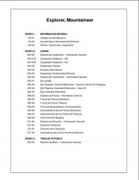
Руководство на испанском языке по техническому обслуживанию и ремонту Ford Explorer и Mercury Mountaineer 1995-2001 годов выпуска.
- Автор: —
- Издательство: —
- Год издания: —
- Страниц: 3613
- Формат: PDF
- Размер: 44,9 Mb
Руководство по ремонту и техническому обслуживанию Ford Bronco II/Explorer/Ranger 1983-1994 годов выпуска с бензиновыми и дизельными двигателями.
- Автор: —
- Издательство: ПОНЧиК
- Год издания: 2003
- Страниц: 438
- Формат: DjVu
- Размер: 93,0 Mb
Руководство по техническому обслуживанию и ремонту автомобиля Ford Explorer 2002-2010 годов выпуска с бензиновыми двигателями объемом 4.0/4.6 л.
- Автор: —
- Издательство: Легион-Автодата
- Год издания: —
- Страниц: 344
- Формат: —
- Размер: —
Руководство по эксплуатации и ремонту автомобилей Ford Explorer и Mercury Mountaineer 2006-2010 годов выпуска с бензиновыми двигателями объемом 4.0/4.6 л.
- Автор: —
- Издательство: Монолит
- Год издания: —
- Страниц: 412
- Формат: —
- Размер: —
Руководство по эксплуатации и ремонту Ford Explorer и Mercury Mountaineer с 2001 года выпуска с бензиновыми двигателями объемом 4.0/4.6 л.
- Автор: —
- Издательство: Монолит
- Год издания: —
- Страниц: 352
- Формат: —
- Размер: —
Руководство по эксплуатации и ремонту Ford Explorer с 2010 года выпуска с бензиновыми двигателями объемом 2.0/3.5 л.
- Автор: —
- Издательство: Монолит
- Год издания: —
- Страниц: 486
- Формат: —
- Размер: —
Руководство по эксплуатации и ремонту Ford Explorer с 2010 года выпуска с бензиновыми двигателями объемом 2.0/3.5 л.
- Автор: —
- Издательство: Монолит
- Год издания: —
- Страниц: 494
- Формат: —
- Размер: —

Руководство по эксплуатации Ford Explorer 2008 года выпуска.
- Автор: —
- Издательство: Ford Motor Company
- Год издания: —
- Страниц: 304
- Формат: PDF
- Размер: 6,2 Mb
Руководство по эксплуатации Ford Explorer 2013 года выпуска.
- Автор: —
- Издательство: Ford Motor Company
- Год издания: —
- Страниц: 599
- Формат: PDF
- Размер: 5,2 Mb
Руководство по техническому обслуживанию и ремонту Ford Explorer, Ford Ranger и Mercury Mountaineer 1991-1999 годов выпуска.
- Автор: —
- Издательство: Легион-Автодата
- Год издания: —
- Страниц: 416
- Формат: —
- Размер: —

Руководства по эксплуатации автомобилей

Сервисная книжка
Скачать (PDF, 331КБ)
Аудиосистема
Руководство по эксплуатации
Скачать (PDF, 5,83Мб)
Навигационная система с DVD-проигрывателем
Руководство по эксплуатации
Скачать (PDF, 6,23Мб)

Ka
Руководство по эксплуатации
Скачать (PDF, 2,37Мб)

Fiesta
Руководство по эксплуатации
Скачать (PDF, 3,29Мб)

Fiesta 2010
Руководство по эксплуатации
Скачать (PDF, 6.38 Мб)

Focus I
Руководство по эксплуатации
Скачать (PDF, 4,02Мб)

Focus II
Руководство по эксплуатации
Скачать (PDF, 8,3Мб)
Скачать (PDF, 8,0Мб)
.jpg "Focus")
Focus II 2009 (рестайлинг)
Руководство по эксплуатации
Скачать (PDF, 7.7 Мб)

Focus III 2011
Руководство по эксплуатации
Скачать (PDF, 9.8 Мб)

Grand C-MAX 2010
Руководство по эксплуатации
» Скачать (PDF, 8.81 Мб)

C-MAX
Руководство по
эксплуатации
Скачать (PDF, 7.75 Мб)

Fusion
Руководство по эксплуатации
Скачать (PDF, 3,43Мб)

Fusion 2010
Руководство по эксплуатации
Скачать (PDF, 5.88 Мб)

Focus C-MAX
Руководство по эксплуатации
Скачать (PDF, 4,45Мб)

S-MAX 2010
Руководство по эксплуатации
Скачать (PDF, 8.43 Мб)

Mondeo
Руководство по эксплуатации
Скачать (PDF, 3,91Мб)

Mondeo 2010
Руководство по эксплуатации
Скачать (PDF, 7.83 Мб)

Kuga 2010
Руководство по эксплуатации
Скачать (PDF, 6.47 Мб)

Maverick
Руководство по эксплуатации
Скачать (PDF, 2,28Мб)

Galaxy
Руководство по эксплуатации
Скачать (PDF, 3,95Мб)

Galaxy 2010
Руководство по эксплуатации
Скачать (PDF, 8.43 Мб)

Transit Connect
Руководство по эксплуатации
Скачать (PDF, 2,82Мб)

Transit Connect 2010
Руководство по эксплуатации
Скачать (PDF, 5.52 Мб)

Tourneo Connect
Руководство по эксплуатации
Скачать (PDF, 3,72Мб)

Tourneo Connect 2010
Руководство по эксплуатации
Скачать (PDF, 8.43 Мб)

Transit
Руководство по эксплуатации
Скачать (PDF, 2,89Мб)

Transit 2010
Руководство по эксплуатации
Скачать (PDF, 6.80 Мб)

Escape
Руководство по эксплуатации
Скачать (PDF, 4 Мб)

Explorer
Руководство по эксплуатации
Скачать (PDF, 4 Мб)

Ranger 2010
Руководство по эксплуатации
Скачать (PDF, 5.56 Мб)
Подробную информацию узнавайте в автосалонах Major Ford:
Вы можете продолжить просмотр:
- Перейти на главную страницу
- Перейти в раздел «Автомобили в наличии»
- Перейти в раздел «Ford с пробегом»
- Перейти в раздел «Вопросы и ответы»