- Manuals
- Brands
- Ford Manuals
- Trucks
- Cargo 2017
- Owner’s manual
-
Contents
-
Table of Contents
-
Bookmarks
Quick Links
Related Manuals for Ford Cargo 2017
Summary of Contents for Ford Cargo 2017
-
Page 2
Ford Otomotiv San A.S. The same also applies for parts of this manual and their use in other applications. Although due care has been taken to make it as complete and accurate as possible, it can stilll be subject to alterations. -
Page 3: Table Of Contents
Contents 1- INTRODUCTION Braking…………..116 6- SPECIFICATIONS Accessories and Parts………. 4 Shifting…………..125 Labels…………..227 Dashboard…………..6 Power take off……….135 Fluid filling capacities……..228 While driving…………137 Engine Specifications……..231 2- SAFETY ECAS Transmission Specifications…… . 233 ( E l ectronica ll y Contro ll e d Air Product Range……….
-
Page 4
ABOUT THIS MANUAL Thank you for choosing Ford. We recommend that you take some time to get to know your vehicle by reading this manual. The more that you know about it, the greater the safety and pleasure you will get from driving it. -
Page 5
INTRODUCTION… -
Page 6: Accessories And Parts
Inspect whether the part has a Ford logo PARTS AND ACCESSORIES SYMBOLS GLOSSARY in case of a repair, and make sure that Ford Your Ford has been built to the highest Original Parts are used. Symbols in this manual standards using high quality Ford Original Parts.
-
Page 7
ACCESSORIES, PARTS AND MODIFICATIONS ON YOUR FORD CARGO VEHICLE Today, there are many non-original parts and accessories are being sold in the market for FORD CARGO vehicles. Using these types of non- original FORD CARGO parts and accessories (even these parts are authorized by some institutions in your country) may have an adverse effect on the safety of your vehicle. -
Page 8: Dashboard
INTRODUCTION Dashboard…
-
Page 9
INTRODUCTION Dashboard Steering Gear Multi-functional handle (left) Centre console/Bottle holder Multi-functional handle (right) Headlamp switch Tachograph Glove box Radio Window regulator control buttons Air Conditioner/Heater switching unit Digital indicator Parking brake Ventilation and air conditioner/heater air Lighter / 12V outlet vents Auxiliary heater digital control unit Storage compartments… -
Page 10
Safety… -
Page 11: Seat Belts
Safety Seat Belts Seat belts provided with your vehicle are the CAUTION WARNING most important on-board safety equipment. Seat belts minimize the risk of injury by While you are fastening your seat belt, ensure Seat belts provide safety inside the vehicle reducing the movement of the occupants in that, when the occupants are seated in vertical…
-
Page 12
Safety Seat Belts Fastening the seat belt WARNING Seat belt cannot provide proper functionality when the belt or lock of the seat belt is damaged. To prevent this, check the seat belts for damage or jamming periodically. Otherwise, seat belt may be torn in case of an accident and cause serious or fatal injuries. -
Page 13: Park Brake Control
Safety Park Brake Control Park brake is placed on the front console. Drive position: WARNING Always apply the park brake after parking the vehicle. Chock the tires if the vehicle is parked Park brake is spring type. If there is not enough pressure in the air tanks, park brake on a slope.
-
Page 14: Tires And Wheels
Safety Tires and Wheels One of the most important safety elements Tire profiles The Condition of the Tires on your vehicle is the tires. Check the tire A minimum profile depth is prescribed for tires Check the following conditions regularly every pressure and condition periodically.
-
Page 15
Safety Tires and Wheels The Aging of the Tires Tire Damages WARNING — Aging of the tires reduces the operation and Tire damages are usually caused by the fol- traffic safety of the tires. Even unused tires are lowing reasons: When your vehicle passes over the sides of aged. -
Page 16: General Safety Warnings
Safety General Safety Warnings After the ignition is on, wait for the red immobi- WARNING WARNING lizer light to dim out before starting. Failure to observe following conditions may Do not carry or store material harmful to the cause accidents which may result in serious health inside the driver cab.
-
Page 17
Safety General Safety Warnings Cleaning of Exhaust Filter The “ERA” mode: The exhaust filter found in Euro 6 vehicles Backlight of buttons “SOS”,”Service” – white light Using exhaust filter cleaning prevention for retains the smut coming from the exhaust gas The “Emergency Call”… -
Page 18
Safety General Safety Warnings… -
Page 19
CONTROLS AND INDICATORS… -
Page 20: 3- Controls And Indicators
CONTROLS AND INDICATORS Instrument Panel Air pressure indicator Engine oil pressure indicator Speedometer Tachometer Engine coolant temperature gauge Fuel gauge Trip computer…
-
Page 21
CONTROLS AND INDICATORS Instrument Panel FUNCTION SYMBOL COLOR CONTROL BUTTON BUZZER Left Signal Lamp Green Multi-functional handle (left) Right Signal Lamp Green Low brake air pressure Instrument Red / Amber Automatic Amber Automatic High Beam Blue Multi-functional handle (left) Alternator Automatic Park Brake Sign Park brake control… -
Page 22
CONTROLS AND INDICATORS Instrument Panel FUNCTION SYMBOL COLOR CONTROL BUTTON BUZZER Oil Pressure Warning Automatic Cold Starting Aid Amber Automatic Height Engine Water Automatic Temperature Trailer ABS/EBS Amber Automatic Trailer right/left turn Green Multi-functional handle (left) signal warning Engine Warning Lamp Amber Automatic Cruise Control… -
Page 23
CONTROLS AND INDICATORS Instrument Panel FUNCTION SYMBOL COLOR CONTROL BUTTON BUZZER Rear Fog Lamp Amber Headlamp switch Fuel Level warning Amber Automatic Air Pressure 1 Green Air pressure control button on the indicator Air Pressure 2 Green Seat belt warning Automatic Amber control button on the control panel… -
Page 24
CONTROLS AND INDICATORS Instrument Panel FUNCTION SYMBOL COLOR CONTROL BUTTON BUZZER Intarder Amber Automatic Oil level warning Automatic Engine brake Amber Multi‐functional handle (right) Information warning Amber Automatic Lane departure warning system Amber Control button on the control panel Emergency braking system Amber Control button on the control panel Icing warning Automatic Park lamp indicator warning Green Headlamp switch … -
Page 25
CONTROLS AND INDICATORS CONTROLS AND INDICATORS Instrument Panel Instrument Panel Display warnings and error warnings. S YMBOL WARNING WARNING DESCIRPTION Exhaust smut filter saturation is above the expected level. This might be caused by the style of driving or the driving time. For the vehicle Drive with fixed speed to be able to conduct automatic filter cleaning, it is advised that you drive the vehicle with a fixed speed above 30kph when you see the to clean exhaust filter… -
Page 26
CONTROLS AND INDICATORS Instrument Panel S YMBOL WARNING WARNING DESCIRPTION SYMBOL WARNING WARNING DESCIRPTION Change the gear lever to neutraland Depress the Rear axle did not raise. First raise the front depress the clutch pedal tostart the Rear axle did not raise. clutch pedal. -
Page 27
CONTROLS AND INDICATORS Instrument Panel S YMBOL WARNING WARNING DESCIRPTION S YMBOL WARNING WARNING DESCIRPTION Rear axle did not Rear axle did not lower. Oil level warning Add oil to engine lower. Handbrake applied. Front axle lowered. Front axle lowered. Vehicle loaded. ECAS Air suspension warning active Soon press any pedal to cancel… -
Page 28
CONTROLS AND INDICATORS Instrument Panel Odometer Tachometer Ensure that the speed does not increase up to red danger zone, especially while driving down the hill. Green zone: economy zone Blue zone: zone where engine brake is activated Red zone: Danger zone Buzzer sounds when you exceed the maximum allowed engine speed. -
Page 29
Inspect whether intervals. the engine belt is broke. • Check for water leaks in the thermostat area on the front of the engine. • Ask the support of a Ford Cargo authorized dealership, if required. -
Page 30
• Park the vehicle in a secure place, stop the If the indicator indicates the circuit air warning is deactivated! engine. Contact a Ford Cargo authorized dealership. pressure, light is illuminated. If you hear the audible warning while driving Air pressure indicator always shows the air stop your vehicle immediately. -
Page 31: Trip Computer
CONTROLS AND INDICATORS Trip Computer SYMBOL First screen if your vehicle First screen if your vehicle 1-Battery voltage DESCRIPTON does not have a lane tracking has a lane tracking system 2-Urea level system…
-
Page 32
CONTROLS AND INDICATORS Trip Computer SYMBOL 1-Mileage 1-Engine total operating hours DESCRIPTON Oil Level 2-Engine operating hours 2-Oil quality status indicator… -
Page 33
CONTROLS AND INDICATORS Trip Computer SYMBOL 1-Average speed 1-Instantaneous fuel 2-Distance that may be DESCRIPTON consumption Oil level (hourglass) covered 2-Average fuel consumption. with the remaining fuel… -
Page 34
CONTROLS AND INDICATORS Trip Computer SYMBOL Drum brake mode On vehicles Disc brake mode with drum brakes, Vehicles With Disc Brakes a warning is issued on the DESCRIPTON Remaining brake lining indicator of the relevant axle Language Selection percentage is displayed for each wheel. the brake lining that has worn out. -
Page 35
CONTROLS AND INDICATORS Trip Computer SYMBOL DESCRIPTON Functions Battery status Axle load… -
Page 36
CONTROLS AND INDICATORS Trip Computer SYMBOL Emergency braking system DESCRIPTON Info menu Error codes info screen collision warning… -
Page 37
CONTROLS AND INDICATORS Trip Computer You may reset trip computer information, which are allowed to be reset, by pressing Trip computer shows information and the button on the lower right of the instrument warnings. panel. Trip computer may be changed by pressing the menu button on the right multi-functional lever. -
Page 38
CONTROLS AND INDICATORS… -
Page 39: Control Buttons
CONTROLS AND INDICATORS Control Buttons RESİM NO SEMBOL AÇIKLAMA RESİM NO SEMBOL AÇIKLAMA A/C ON/OFF EMPTY RECIRCULATION SEMI-TRAILER BRAKE MIRROR HEATING REAR AXLE LIFTING WINDSHIELD HEATER FRONT SUSPENSION CONTROL BUTTON ASR CANCEL/ ASR ACTIVE TAG AXLE LIFTING II SWITCH ASR CANCEL/ ASR ACTIVE DIFFERENTIAL LOCK POWER AUTOMATIC TRANSMISSION MODE SELECTION…
-
Page 40: Multi-Functional Handles
CONTROLS AND INDICATORS Multi-functional Handles Multi-functional handle (left) It is placed on the left side of the steering. 6a- High Beam (Flasher) Switch positions are as follows. Flasher is operated by pulling the handle briefly and releasing it. 1. Horn 6b- High Beam (Continuous) 2.
-
Page 41
CONTROLS AND INDICATORS Multi-functional Handles Multi-functional handle (right) On vehicles without Intarder and with EBS 1 step engine brake 2 step engine brake It has 5 steps in vehicles with Intarder. It has 2 steps in vehicles without Intarder. 1st stage 100% engine brake Engine Brake Bes,des while it is in «0»… -
Page 42
CONTROLS AND INDICATORS Multi-functional Handles Vehicles with Intarder: Engine Brake Intarder Bremsomat Reduced Brake Power Bremsomat (0%-100%) Intarder 1 Reduced Brake Power 25% Max. Brake Power Intarder 2 Reduced Brake Power 50% Max. Brake Power Intarder 3 High Brake Power 75% Max. -
Page 43: Tachograph
CONTROLS AND INDICATORS CONTROLS AND INDICATORS Tachograph Tachograph Tachograph ( Just stoneridge Driver Displays (DDS enabled) Tachograph) Use the button to scroll up/ down to show one of the displays below. For more details on Driver Displays, please visit Insert your card SE5000.com Manual Entries During the manual entries procedure you can…
-
Page 44
CONTROLS AND INDICATORS Introducing Your Vehicle Tachograph Indicators Rest until now? YES 7. Continue with step 4 in chapter Rest until Rest until now? NO now? YES. Scenario: The driver card was withdrawn at Scenario: You arrived at Screen Messages the end of the last working day and inserted 15.23, 23/11 and when the new… -
Page 45
CONTROLS AND INDICATORS CONTROLS AND INDICATORS Tachograph Tachograph… -
Page 46
CONTROLS AND INDICATORS Tachograph VDO Tachograph(DTCO-1381) Switch on the ignition. ► Manual inputs (* required only in ADR model) Installing driver card The 1st driver who shall drive the vehicle A According to the regulation, the activity inserts their own driver card to the 1 that cannot be recorded on the driver card slot with chip upwards and arrow card must be added by manual input. -
Page 47
CONTROLS AND INDICATORS Tachograph Path to follow as a principle For 4 seconds, the last card removal date and time is • Select any function or activity you like from the in- shown in local time (symbol «•») put area or key in the numerical tuşlayın. -
Page 48
CONTROLS AND INDICATORS Tachograph Discrete functions are temporarily disabled while the driver card is being read: • Calling menu functions • Requesting tachograph card • Confirm input with «Yes». A message is displayed when a menu button or card eject button is pressed. •… -
Page 49
CONTROLS AND INDICATORS Tachograph ► Country input during manual input Country selection If the button is pressed in the following 30 Last selected country is displayed first. Then seconds, you can continue the input operation. the last input four country is displayed with / At the end of this duration, or when driving buttons Marking: The colon in front of country starts;… -
Page 50
CONTROLS AND INDICATORS Tachograph Adding «resting time» activity Example 1: Card inserting operation Card retrieval (15.04.15) Insertion (18.04.15) 16:31 Local time 07:35 Local time Activity confirmation Adding resting time Please note: Input is realised in local time. Keep button pressed Jumps to the last input field automatically (minute flashes). -
Page 51
CONTROLS AND INDICATORS Tachograph ► Continuing the shift Example 2: Card inserting operation Insertion (25.02.15) Card retrieval (24.02.15) 02:30 Local time 23:32 Local time Inputting activities / date Completing activity Please note: Input is realised in local time. Set first activity and confirm. -
Page 52
CONTROLS AND INDICATORS Tachograph ► Continuing the shift and adding activities to previous shift Example 3: Card inserting operation Insertion (25.02.15) Card retrieval (24.02.15) 02:30 Local time 23:32 Local time Inputting activities / date Country input Before activity Shift end addition Shift start Completing activity… -
Page 53
CONTROLS AND INDICATORS Tachograph After the ignition is turned on or off, the Setting the activities For the assistant driver, press 2nd automatically changing event (1) and/or (2) is driver activity button; displayed on standard indicator (a) and flashed Driving duration (automatic during ►… -
Page 54
CONTROLS AND INDICATORS Tachograph Personal information Note It can be programmed on customer request which activity the DTCO 1381 shall switch to Name and surname automatically after ignition is turned on by the Driver card or driver license authorized workshop; number ►… -
Page 55
CONTROLS AND INDICATORS Tachograph If an incident repeats continuously, please apply to an authorized expert workshop! Pikto / Reason Meaning Precautions The possible reasons may be as below: Confirm the message. Security Violation • Error in data memory, data security cannot be ensured in DTCO 1381 tachograph any more. -
Page 56
CONTROLS AND INDICATORS Tachograph Behaviour in low/excessive voltage situation Case 3: If the symbol is displayed continuously even when the vehicle voltage is correct, ap- This incident is equivalent to a voltage cut-off ply to an authorized expert workshop! Standard indicator (a) is displayed automatical- If the DTCO 1381 tachograph malfunctions, ly and DTCO 1381 cannot perform tachograph it is your obligation to record activities with… -
Page 57
CONTROLS AND INDICATORS Tachograph Country codes Value allocations Liechtenstein Poland Austria FR/FO Faroe Romania Albania Georgia San Martno Andorra Russian Federation Greece Armenia Hungary Sweden Azerbaijan Croatia Slovak Republic Belgium Italy Slovenia Bulgaria Ireland Serbia Bosnia-Herzegovina Iceland Turkmenistan Belarus Kazakhstan Turkey Switzerland Luxembourg… -
Page 58
CONTROLS AND INDICATORS Tachograph ► Region signs Value allocations — Spain Andalusia Aragonia Aturias Cantabria Catalania Castile — Lean Castile — La Mancha Valencia Extremadura Galicia Balear Islands Canary Islands La Rioja Madrid Murcia Navarra Basque… -
Page 59
CONTROLS AND INDICATORS Tachograph Switch on the ignition. Removing driver cards Card request during manual input (* required only in ADR model) Remove the card from the card slot 1 A As a rule, the driver card can remain in the Set the appropriate activity;… -
Page 60
CONTROLS AND INDICATORS Tachograph ► Menus after driver card is removed Step / menu display Remark Description The surname of the driver is displayed. Status bar dis- plays that the DTCO 1381 tachograph transfers data to Select the country with buttons and the driver card. -
Page 61
CONTROLS AND INDICATORS Tachograph ■ Changing driver/vehicle during operation • Written tachograph papers (3) Case 2: Driver 1 and/or Driver 2 leaves • and handwritten records belonging to the activity when required the vehicle Related driver requests their own driver card, when necessary prints out the daily report and removes driver card from DTCO 1381 tachograph. -
Page 62
CONTROLS AND INDICATORS Tachograph ■ Displays and button explanations (1) Display (2a) 1st driver buttons (2b) Driver 1 combi button (3) Card slot 1 (4) Data download interface (5a) Driver 2 buttons (5b) Driver 2 combi button (6) Card slot 2 (7) Printer drawer opening button Double button (8) Cutting edge… -
Page 63
CONTROLS AND INDICATORS Tachograph Pikto 1 Reason Meaning Precautions Printing… Selected function feedback. These warnings are automatically deleted in three seconds. There is no need for any Input recorded Feedback that DTC01381 tachograph recorded the operation. input. Display not possible! Data cannot be displayed as long as printing continues. -
Page 64
CONTROLS AND INDICATORS Tachograph ■ Maintenance and cleaning • If the license plate of the vehicle is Archive the data or keep the document for changed, coming questions. ► Cleaning DTCO 1381 tachograph • When the UTC time deviates for more than Clean the device body, screen and buttons 20 minutes. -
Page 65
CONTROLS AND INDICATORS Tachograph ■ Automatic activity setting upon turning ignition on/off Warning! Automatically set activity … The defined activity following ignition on/off … after ignition is turned on … after ignition is turned off can be programmed by the vehicle manufac- turer! Break / resting period Break / resting period… -
Page 66
CONTROLS AND INDICATORS Tachograph simulator unit… -
Page 67
OPERATION… -
Page 68: Opening And Closing Of The Vehicle
WARNING Ignition key has an immobilizer feature against vehicle theft. New keys shall be programmed by Ford Otosan authorized dealerships. • Fuel tank • Urea tank (only on Euro 5 and Euro 6 vehicles) •…
-
Page 69
New remote controls shall be introduced seconds. to the vehicle when a new control is This feature also includes the opening of purchased. Please visit a Ford authorized sunroof with the windows on vehicles with dealer for the introduction of the controls. power roof. -
Page 70
OPERATION Opening and closing of the vehicle Getting In and Out Of the Vehicle Outer Handle Door Inner Latch Use the 3 points principle while getting in and out of the vehicle. Do not hold the steering wheel while getting in the vehicle. Don’t: Do not try to get in the vehicle by holding the steering wheel instead of the handle. -
Page 71
OPERATION Opening and closing of the vehicle Windows Window moves to opening or closing direction When the flasher signal is received, bring the while the opening/closing buttons are pressed. window to the top level with a single press Operation is stopped automatically when the and hold the button until off/on feedback is window reaches uppermost or lowermost received from the locks. -
Page 72
OPERATION Opening and closing of the vehicle Opening/closing the front hood WARNING Hold and press the middle of the hood while opening and closing the hood. Do not press on one side of the hood. To open: It can be opened by the ignition key. Turn the key anticlockwise. -
Page 73: Cab Ventilation
OPERATION Cab Ventilation Manual Roof Flap Power Roof Flap Power roof moves to opening or closing direction while the opening/closing buttons are pressed. Operation is stopped automatically when the power roof reaches uppermost or lowermost position. Buttons are active while the ignition is on.
-
Page 74: Seats And Beds
OPERATION Seats and Beds Seats Height adjustment Shock absorber adjustment Fast lowering Horizontal yield Fore and aft adjustment Resting position Seat inclination adjustment Seat depth adjustment Armrest Armrest inclination adjustment Heater Backrest adjustment Lumbar support…
-
Page 75
OPERATION Seats and Beds Fast lowering Height adjustment Shock absorber adjustment Seat may be lowered to the lowest position Height adjustment is applied in 8 steps. The absorbing harshness of the seat may be by pressing the button and securing it (before adjusted without any steps between soft and getting off the vehicle). -
Page 76
OPERATION Seats and Beds Horizontal yield Fore and aft adjustment Seat inclination adjustment Operating the horizontal yield may be helpful Fore and aft adjustment is performed by in some operating conditions. Then, the moving the seat forward or backward while impacts on the movement direction of the pulling the lock lever. -
Page 77
OPERATION Seats and Beds Seat depth adjustment Armrest inclination adjustment Armrests The inclination of armrests on the fore-aft direction can be changed by rotating the button. The front end of the moves upward when you rotate the button outwards (+ direction), and downwards when you rotate the button inwards (- direction). -
Page 78
OPERATION Seats and Beds Backrest adjustment Heater Electrical heaters on the backrest and seat To unlock the backrest, pull the lock lever cushion are operated in two steps by pressing upwards. Do not press on the backrest while the seat heater switch. opening the lock. -
Page 79
OPERATION Seats and Beds Maintenance Lumbar support WARNING Dirt may hinder the operation of the driver Discharge the air by pressing the rapid seat. Keep your seat clean to prevent this! lowering button when you are getting off the vehicle. This would increase the service life of Trims are not required to be removed from the the seat mechanism. -
Page 80
OPERATION Seats and Beds… -
Page 81
OPERATION Seats and Beds DRIVER SEAT PASSENGER SEAT 1- Seat inclination adjustment: Inclination of the seat can be adjusted between 2° and 12°. 2- Shock absorber adjustment: Shock absorbers can be set in 4 positions from soft to hard with the adjustment button. Absorbers are adjusted to a softer setting when the button is pulled up and a harder setting when the button is pushed down. -
Page 82
OPERATION Seats and Beds DRIVER SEAT PASSENGER SEAT 7- Seat depth adjustment: 60mm . Allows the setting of the depth of the seat within 60 mm in 5 stages. 8- Seat heating: On/off button can be used to turn on the seat heater. Heater is deactivated after the seat is heated by switching off the button. -
Page 83
OPERATION Seats and Beds Single Bed Upper bed CAUTION Do not carry load or occupants while the vehicle is moving. There is a risk of injury for both the driver and the passenger as it will be scattered around during braking and manoeuvring. CAUTION * Upper bearing is optional for high roof cabs. -
Page 84: In-Cab Storage Compartments
OPERATION In-cab storage compartments Upper Console Shelves CAUTION (Vehicles with high roof) Do not put heavy items on upper console. Glove box In the rear part of the vehicle, there are 2 shelves and 1 compartment with net both on the right and left.
-
Page 85
OPERATION In-cab storage compartments Cigar lighter Centre console Ashtray Hold the heated cigar lighter only from its Ashtray is placed on the center of the console. The multifunctional center console placed handle. Removable ashtray mechanism provides ease between the driver’s seat and the passenger Only use the lighter when the traffic allows you of use in the desired position for the driver. -
Page 86
OPERATION In-cab storage compartments 12 V outlet CAUTION Do not touch the cigar lighter end when it is hot. CAUTION Do not hold the cigar lighter element pressed in after it is released. 12 V outlet may provide power for devices up to 100W. -
Page 87: Steering
OPERATION Steering CAUTION A minimum of 7 bar air pressure is required to adjust the steering mechanism. If the vehicle air pressure is low, operate the vehicle to fill up to the air tubes. You can adjust the steering angle and height Turn the knob on the steering column in the most comfortable position for you while anticlockwise.
-
Page 88: Mirrors
OPERATION Mirrors Mirrors Adjust the rear view mirror (no. 1) by the rotating knob on the driver’s door armrest. Bring the knob to position for the adjustment of the driver’s side mirror. There are 4 different types of mirrors on your Adjust the mirror by moving the knob forward vehicle: and backward and left and right, then bring the…
-
Page 89
OPERATION Mirrors Mirror Heater Mirrors 1 and 2 have heaters. Use the heater for ease of view on winter days. To activate the heater: Press “mirror heater’’ switch on the control panel while the ignition switch is at position 2. To deactivate the heater: heater shall be deactivated automatically after 10 minutes. -
Page 90: Lighting
OPERATION Lighting Headlamp Switch Headlamp levelling adjustment WARNING Headlamp levelling shall be adjusted before getting on the road to prevent dazzling the eyes of the drivers of the vehicles in the upcoming traffic in different road conditions. CAUTION The current capacity of the switch may only cover for the available system.
-
Page 91
OPERATION Lighting weather conditions headlamps may Direction Indicator Lever (If Equipped) Autolamps automatically turn on and off. WARNING Note: It may be necessary to switch your The autolamps switch position may headlamps on manually in severe weather not activate the headlamps in all low conditions. -
Page 92
OPERATION Lighting Front fog lamp Rear fog lamp Rear fog lamp is placed on the headlamp Front fog lamp is placed on the headlamp control panel. Turn this switch on to obtain control panel. better visibility and be visible to the incoming Turn this switch on to obtain better visibility traffic in foggy conditions and where the and be visible to the incoming traffic in foggy… -
Page 93
OPERATION Lighting Interior lamp Dome (pilot) Lamps Reading lamp Interior lamp is placed over the windshield on the center area. It is turned on/off by the switch on it. – Position: Continuously lit. – Position: Lamp does not turn on. –… -
Page 94
OPERATION Lighting High roof vehicles Interior lamp Dome (pilot) Lamps Interior lamp is placed over the windshield on the center area. It is turned on/off by the switch on it. : Illuminates the driver side dome lamp. : Illuminates the passenger side dome lamp. Center switch has 3 positions. -
Page 95: Window Washing And Heating Systems
OPERATION Window Washing and Heating Systems Windshield Washer Reservoir Autowıpers (If Equipped) Water spray The autowipers feature uses a rain sensor. You will find it on the lowe center part of the windscreen. The rain sensor monitors the amount of moisture on the windshield and automatically turns on the wipers.
-
Page 96
OPERATION Window Washing and Heating Systems Windshield Heating (Available on vehicles Note: Once you choose a different speed or Note: Wet or winter driving conditions with ice, park position on the wiper switch, autowipers snow or salty road mist can cause inconsistent with Cold Climate pack only) feature will be deactivated, and wipers will and unexpected wiping or smearing. -
Page 97: Circuit Breakers
OPERATION Circuit Breakers Use the circuit breakers to disconnect the Using the external switch Vehicles without ADR electrical current in your vehicle. Vehicles with ADR To cut the circuit off An ADR switch shall be available on Lift the safety cover. vehicles that transport flammable, explosive, Raise the switch.
-
Page 98
OPERATION Circuit Breakers Turn the switch counter-clockwise to cut the circuit off. Turn the switch clockwise to re- activate the electricity supply of the vehicle. CAUTION Use the circuit breaker at least 2 minutes after you have stopped your vehicle. Otherwise, engine electronic control unit (and Denox control unit, if available) may be damaged. -
Page 99: A/C And Heater
OPERATION A/C and Heater Air conditioning To operate the A/C of your vehicle, bring the heat control Press the A/C and recirculation buttons on the front panel. To cold (blue) position while the engine is on. – Blower speed setting –…
-
Page 100
OPERATION A/C and Heater Auxiliary heater (Webasto) NOTE: To get a better performance from your vehicle’s A/C, turn it on even in winter for 5 Dry Type Heater minutes every 15 days. It is not required to set the knob to cold position during this us- age. -
Page 101
OPERATION A/C and Heater When error codes F01 / F02 /F07 are read on Wet type heater CAUTION the cab heater digital indicator, fill the fuel level and turn the cab heater switch off and on. Webasto pump is delicate. High quality diesel Repeat this procedure until the air inside fuel shall be used against freezing. -
Page 102
OPERATION A/C and Heater Wet type webasto fuel tank Controls CAUTION The unit intakes fuel supply from the specially Time Indicator Operating Indicator designed fuel tank that houses the freezing- Temperature selection proof (Arctic Diesel, kerosene etc…) fuel. Turn off additional heating system(s) when Record Location refuelling. -
Page 103
Heater Turns Off By Itself Maintenance Malfunction Description Precaution • We recommend that the heater is inspected in Ford authorized workshops No ignition during starting. Turn off/on the heater once in the start of each winter season. Flame extinguishes during operation Turn off/on the heater once •… -
Page 104
OPERATION A/C and Heater Error (group) Additional information during computerized diagnosis Error Remedy code F 01 Does not start 02 No flame even after restarting 82 Does not start during Check fuel supply (tank empty, lines blocked) Clean burner testing insert, Petrol: Replace flame sensor Diesel: Replace overheating sensor / control unit. -
Page 105
OPERATION A/C and Heater Error (group) Additional information during computerized diagnosis Error Remedy code F 08 Drive unit 89 Fault or short circuit to +Ub Replace the drive unit (combustion and hot air blower) (combustion and hot 09 Short circuit to ground in the switched drive unit wire Eliminate the cause of the blockage / difficulty in move- air blower) (combustion and hot air blower) or drive unit is exces-… -
Page 106
OPERATION A/C and Heater Error Codes Control device error No start (after 2 start attempts) Flame interruption (minimum >5) Low voltage or high voltage Premature flame detection Flame detector (petrol heater) Interruption or short circuit in temperature sensor Short circuit in dosage pump Interruption or short circuit in fan motor or overload on fan motor or fan motor blocked Interruption or short circuit glow plug Overheating… -
Page 107
OPERATION A/C and Heater Auxiliary Heater (EBERSPÄCHER) Ending the heating operation by pressing CAUTION the button for a long time Press the key for 2 seconds to end all auxiliary unit function It may be activated functions. by Eberspaecher authorized services. ventilation symbol is displayed only if the Ending the heating operation by pressing operating unit is connected to heaters that… -
Page 108
OPERATION A/C and Heater Ending the ventilation operation with aux- Ending the ventilation operation by press- Press the key to confirm the settings. ing the button for a long time iliary unit by pressing the button for a long time Press the key more than 2 seconds, all Ending the heating operation with auxiliary… -
Page 109
OPERATION A/C and Heater Activation of the saved program Setting the operating time Set the minutes with keys and confirm With keys, bring the program to “ON” Set the operating period with keys with the key. and confirm with the key. -
Page 110
OPERATION A/C and Heater Setting the date CAUTION With keys, select symbol and The auxiliary heater digital control confirm with the key, programming feauture is deactivated for safety reasons for the vehicles (with ADR) carrying Set the date with keys and confirm hazardous substances with the… -
Page 111
OPERATION A/C and Heater In the event of a fault the followıng dısplays are possıble REMEDY / CUSTOMER DISPLAY DESCRIPTION Automatic detection is active. The EasyStart Timer has been discon- «Wait until the automatic detection has nected from The power supply and then finished, then set the time and weekday. -
Page 112
OPERATION A/C and Heater Heater Turns Off By Itself CAUTION If you cannot resolve the fault by yourself, Fault Description Remedy please contact your authorized service. Does not ignite during operation Turn the heater off and on once Flame goes off during operation Turn the heater off and on once Entering the service menu to learn the error code: Heater overheats… -
Page 113
OPERATION A/C and Heater Heater Bring the heat control to red position for hot You can adjust the fan speed in 3 steps. Adjust the blowing direction air flow. 0: Off 1: Low speed blows to the windshield. 2: Middle speed 3: Fast blows from opposite direction. -
Page 114: Driving
OPERATION Driving Before taking off: Starting the engine CAUTION Wait for the period determined by the electronic control unit (10 to 40 seconds) before starting again after a start failure. Do not attempt to start in this period. Cold Start •…
-
Page 115
When the user We advise you on that adjustments on the exceeds the specified maximum start duration, air deflector shall be performed by FORD To stop the engine he is prevented from starting again. Do not stop the engine immediately when the… -
Page 116
OPERATION Driving Cruise Control Driving speed is set by the multifunction lever CAUTION on the right of the steering. Engine electronic control unit adjusts the throttle setting required Vehicle cuts throttle if the set speed is for driving the vehicle at the set speed. Vehicle exceeded, and engine brake is activated if is driven in the set speed without the need for the engine speed is over 1000 rpm. -
Page 117
OPERATION Driving Hill holder On Vehicles with Manual Transmission: On Automated Manual Transmissions: 1- Stop the vehicle with service brake. 1- Stop the vehicle with service brake. 2- Activate the hill launch assist by pressing 2- Activate the Hill holder by pressing the the button on the center console. -
Page 118: Braking
OPERATION Braking Disc brake system Brake System: Arvin Meritor Elsa 225H air disc brake with sliding brake calliper. Disc: 430 mm anti-conical disc with air ducts. System Air Pressure: 10,5 bar Brake friction pads The thickness of the new linings is 19mm. Linings shall be replaced when the thickness becomes lower than 3 mm.
-
Page 119
OPERATION Braking Disc brake system Drum Brake System The thickness of the new discs is 45 mm. Discs shall be replaced when the thickness becomes lower than 39 mm. Check the disc thickness every three months as the service life of the disc shall differ greatly due to causes such as vehicle load, operating conditions etc. -
Page 120
If the thickness of the lining remaining on the brake pad is less than 8mm, we recommend that you shall have your lining replaced in a Ford Cargo authorized service immediately. -
Page 121
OPERATION Braking Emergency brake bellows Discharging the emergency bellows CAUTION Brake air bellows on the drive axle of your To discharge the emergency bellows, turn the vehicle have emergency feature. Emergency bolt behind the bellow in tightening direction To start park brake mechanism again, please bellows are activated in 2 conditions: (clockwise) completely. -
Page 122
OPERATION Braking Engine brake (Standard) Activation of the engine brake Intarder is activated by the 5 step lever on the right of the steering. Engine Brake Figure-1 Figure-2 Engine Brake Intarder 1. Range Reduced Brake Power Bremsomat Reduced Brake Bremsomat (0%- Power 100%) Your engine provides the engine brake feature… -
Page 123
OPERATION Braking Bremsomat: WARNING When the retarder lever is pulled 1 step while driving downhill, intarder is activated in the Intarder oil is cooled with the engine coolant. required amount so that the vehicle speed Check whether the coolant is heated hold constant. -
Page 124
OPERATION Braking Automatic hybrid brake mode CAUTION If the right multifunction lever is brought to any position other than (0), automatic hybrid brake mode is deactivated until the lever is brought to position (0) again. Air tubes Drain the water in the tanks every day. Pull the ring attached to the cock until all air is discharged to drain the water inside the tanks. -
Page 125
OPERATION Braking Air Dryer (APU) Auxiliary Air Line CAUTION Air drier filter shall be replaced in periodical maintenance intervals. If the drier filter does not operate properly, it may cause damage to itself and the air valves. When air bleeding is required for special The air drier unit on your vehicle includes functions (e.g. -
Page 126
OPERATION Braking The pedal activation has to be carried out on • Pedal decrease until fully release, without Reverse test request There are some kind of failures which the following way: any condition. can’t be detected by EBS directly, only via •… -
Page 127: Shifting
OPERATION Shifting 16S 2230 Manual transmission and shifting Note: To shift from low range to high range during 2- Driver wants to shift from 6th to 5th, but switches acceleration in transmissions with 1H gear system: the latch to low range inadvertently when the vehicle 1.
-
Page 128
OPERATION Shifting In order to shift into gear, fully press the clutch Do not use reverse gear when the and in the high range when the latch is pedal before shifting and remove your foot transmission is in high range. pressed upwards. -
Page 129
OPERATION Shifting • The situations that the driver may experience Transmission Information on the display: with the prevention mechanisms are listed «Shift up» warning: engaged gear is below: smaller than required by the engine speed. 1. Driver wants to shift from 4th to 5th, but forgets the Shift up. -
Page 130
Automated transmission and shifting Shift Lever: Information Display: A transmission with 12 forward and 2 reverse gears is provided in Ford Cargo vehicles with automated transmission*. ** No clutch pedal is available in the vehicle. Clutch release/clutch operation is performed by the mechanism controlled by the electronic control module. -
Page 131
OPERATION Shifting Forward movement: Forward movement: • Clutch movement and shifts are performed CAUTION automatically. 1- Bring the rotating knob to position D. • Gears may be corrected manually. 2- Release parking brake. Do not shift to reverse before stopping the •… -
Page 132
Do not to exceed the maximum engine speeds wait for a while. allowed during manual operation. Display warnings: STOP Transmission is faulty. Stop the Transmission warnings are displayed as 2 digit vehicle and contact a Ford Cargo authorized abbreviations on trip computer. dealership. -
Page 133
OPERATION Shifting Clutch lining wear has reached limit value. Ple- WARNING ase visit a Ford Cargo authorized dealership in Reverse, high range the shortest possible time. Attempting to shift while the air pressure is low may cause shifting of the transmission Reverse, low range to neutral. -
Page 134
When NS warning is displayed, trans- mission control unit indicates that the vehicle is left in D without moving for a long time. Shift to neutral. Transmission oil temperature has reached upper limit. Stop the vehicle. Please contact a Ford Cargo authorized dealership. -
Page 135
OPERATION Shifting Off-road driving mode Oscillation mode On vehicles with an automatic transmission; When used at difficult conditions such as provides driving in terrain conditions by mud, snow etc. on vehicles with automatic preventing the torque reduction in drive wheels transmission, it allows rapid opening and with the lowest possible number of shifts. -
Page 136
OPERATION Shifting High speed drive mode Oscillation mode It is used when vehicle is required to shift When used at difficult conditions such as up at higher engine speeds on vehicles with mud, snow etc. on vehicles with automatic automatic transmission. transmission, it allows rapid opening and closing of the clutch and thus prevents that High speed drive mode is activated by… -
Page 137: Power Take Off
Cargo vehicles allows that the engine is ope- • PTO cannot be activated when the vehicle rated at a constant speed when PTO is activa- is moving. ted. Speed parameter on the control unit may be set by the Ford Cargo authorized dealers.
-
Page 138
OPERATION Power take off Symbol shall be illuminated on the functions section of instrument when PTO is active. PTO valve switch.. Control unit is used for lowering the bed in dump trucks. Button #12 is used for slow lowering, button #13 is used for fast lowering operation. -
Page 139: While Driving
OPERATION While driving WARNING WARNING WARNING In the vehicles with engine driven power Make sure that the driven wheels are held on The driving, braking and manoeuvring output (Engine-PTO), Cargo Concrete Mixer the road while driving, and especially on the behaviour of the vehicle varies according to series in particular, the angle of the shaft off-road.
-
Page 140
After driving off-road period of time while driving over the obstacles. brake system is checked by a FORD OTOSAN • Stop the vehicle and engage a lower gear WARNING authorized dealership. -
Page 141
OPERATION While driving Fuel consumption Workstations Fuel consumption depends on the conditions Fuel consumption depends on the conditions below: below: • Highland conditions • Model of the vehicle • Traffic in cities and short distances • Driving style • Vehicle load •… -
Page 142: Sus P Ension )
OPERATION ECAS (Electronically Controlled Air Suspension) Manual Control Unit (In Vehicles with Air Using Manual Control Unit (Only In Vehicles Ignition switch should be in position Suspension with Four Bellows) with Air Suspension with 4 Bellows) to activate the air control system by the «manual control unit».
-
Page 143
OPERATION ECAS (Electronically Controlled Air Suspension) Manual Control Unit (In Vehicles with 1. Ignition switch should be in position 6 x 2 Air Suspension) activate the air control system by the «manual control unit». work has been performed. 2. Functions desired can be performed after pressing the driven axle selection button or lifted axle selection button. -
Page 144
OPERATION ECAS (Electronically Controlled Air Suspension) Front Axle Height Adjustment Mechanism An audible warning signal with a gong sound is heard and symbol is displayed on Front axle lifting system shall be deactivated the indicators. when the ignition is switched off and vehicle When the rear axle lowered drive level control shall be lowered to drive level. -
Page 145: Air Suspension Mechanical Level Adjustment
OPERATION Air Suspension Mechanical Level Adjustment 32XX S Self Steering In Vehicles with CAUTION Air Suspension In reverse manoeuvres you should wait 8 to 10 seconds after the forward manoeuvre to allow the wheels turn in the opposite direction. CAUTION Do not perform a reverse manoeuvre when the gear is in neutral.
-
Page 146: Tag Axles
OPERATION Tag Axles System description the Information menu of the instrument panel Vehicle Speed and the light on the button is not illuminated. Axle raising feature in 6×2, 8x2C and 8x2S Axle raising functions are cancelled for safety Not allowed conditions: Series trucks with mechanical suspension is reasons if the vehicle speed is over 30 km/h.
-
Page 147
OPERATION Tag Axles by the system. Therefore, you should avoid unstable loading of the truck in order to use the axle raising system better and to obtain a better efficiency. Pressing the Button While Axle is Raised Unloaded Vehicle Condition (For 8x2S only) If the system allows, relevant axle is lowered, icon disappears from the Function menu of the In 8x2S vehicles, is automatically raised and… -
Page 148
OPERATION Tag Axles the ground, or the self-steered axle shall not lowered when the tag axle is raised. To control these situations, system rejects the relevant requests and a warning message is displayed on the Information Menu. WARNING WARNING Axle load limits are increased 30% up to a Sensors are calibrated during production, Sensor positions and maintenance speed of 30 km/h to obtain a better traction… -
Page 149: Ebs — Esp
OPERATION EBS — ESP 4-Automatic Traction Control: CAUTION CAUTION Main purpose of this function is to prevent skidding of driven axle wheels. ESP is an auxiliary brake system. Emergency brake assist cannot increase the a) Braking power control: The speeds of the Always remember that no system can maximum capacity of braking power.
-
Page 150
OPERATION EBS-ESP ASR Deactivation Mode: You may want to disable ESP on soft road conditions. In this case, press the ESP cancel switch located in the centre console. light is illuminated on the display when this mode is active. -
Page 151: Differential Lock
OPERATION Differential Lock What is differential lock? To activate the Differential Lock Differential lock is a system that increases 3) X2 vehicles FDL light will be the capacity of transmission of power to the Follow the procedure below to activate the illuminated on the instrument panel when surface.
-
Page 152
«3rd differential». surface and stop the vehicle completely. Rules to be observed in the usage of IADL Ford-Otosan Inter-Axle Differential Lock 2) Drive the vehicle very slowly by applying the (IADL) is driver controlled system operated by accelerator slowly to deactivate the differential Activating the IADL: the pressurized air;… -
Page 153
OPERATION Differential Lock 2) Turn the IADL switch on. 4) You can continue driving observing the legal CAUTION speed limits according to flow of the traffic. On tractor vehicles Deactivate the differential lock when driving the tractor vehicles down the slopes. Trailer may be folded due to the loss of the vehicle dynamics. -
Page 154: Lane Departure Warning System
OPERATION Lane Departure Warning System • Lane markings are not detected due to The sensor may incorrectly track lane markings WARNING vehicles driving in front such as other structures or objects. This can result • The part of the windscreen where front in a false or missed warning.
-
Page 155
OPERATION Lane Departure Warning System Switching the System On and Off Note: If the turn signal has been active for over 1 minute, LDWS is not suppressed due to active turn signal anymore. When the ignition is turned ON, LDWS will be automatically active unless there is no error. -
Page 156
Note: If the information message below appears on the cluster display, this means LDWS needs to be inspected by an authorized Ford Trucks Service, and LDWS will not be available till the inspection. -
Page 157: Emergency Braking System
OPERATION Emergency braking system Advanced Emergency Braking System Emergency Braking: If the collision is still found to be imminent, the system may apply full braking to reduce Principle of operation the impact damage or avoid the crash completely. If your vehicle is rapidly approaching another Note: AEBS is not active if you are driving below 15kph.
-
Page 158
AEBS may not work as expected if your vehicle vehicle, serious personal injury or death. If something hits the front end of your vehicle is not inspected by Ford Trucks Service on regular The system does not react to cyclists, or damage occurs, the radar sensing zone may maintenance checks. -
Page 159
OPERATION Emergency braking system How to maintain Advanced Emergency Braking Note: If something hits the front end of your Front Camera Low System? vehicle or damage occurs, the radar sensing zone Visibility Clean may change. This could cause missed or false Note: If a message regarding a blocked radar Screen vehicle detections. -
Page 160
AEBS will get deactivated You can abort an AEBS triggered emergency to prevent possible unnecessary interventions. braking intervention, if you; In such a case, visit an authorized Ford Trucks Service to activate the system. • depress the accelerator pedal beyond the… -
Page 161
OPERATION Emergency braking system If you are brought to a halt via an AEBS triggered emergency braking, AEBS will keep the brakes until you override by; • depressing the accelerator pedal • pressing the AEBS deactivation switch. WARNING Important Note: In such a situation, take control of your vehicle and make sure that you activate the parking brake before leaving your vehicle. -
Page 162: Useful Information
OPERATION Useful Information CAUTION! PLEASE HAVE IT CALIBRATED IN AN AUTHORIZED DEALERSHIP SPECIFIED IN THE TACHOGRAPH MANUAL PROVIDED…
-
Page 163
• Use oil and air filters approved by Ford Otomotiv Sanayi only. 4. Injector pump • Injector pump available in your vehicle is completely adjusted and sealed in factory. -
Page 164
OPERATION Useful Information 6. Wheel alignment 10. Upper bed • Have the front alignment adjustment of your vehicle checked, • Do not lower the upper bed while the vehicle is moving. and have it adjusted by service support if needed in the first 1000 to 5000 km. -
Page 165
This feature would provide significant fuel saving and you shall control by using the «off» position in speed control or by pressing enjoy the privilege of being a Ford Cargo owner. the clutch or brake pedal as specific to application. -
Page 166: 5- Maintenance And Service
MAINTENANCE AND SERVICE…
-
Page 167: Attaching And Detaching A Trailer
MAINTENANCE AND SERVICE Attaching and Detaching a Trailer 5th Wheel (Platform) — Attaching the Semi- (see Figure 1 and Figure 2) position automatically. (see Figure 5) Trailer 4-Position the vehicle so that there is a (for 5th wheels of SAF HOLLAND brand) clearance of 20 to 50 mm between the bottom of the semi-trailer and the 5th wheel platform (see Figure 1)
-
Page 168
MAINTENANCE AND SERVICE Attaching and Detaching a Trailer attention to the voltage of the consumers on CAUTION the semi-trailer before connecting the cable. 5th Wheel (Platform) — Detaching the Semi- If any of the above conditions are not met, Trailer restart the entire locking procedure from the (for 5th wheels of SAF HOLLAND brand) 2nd step. -
Page 169
MAINTENANCE AND SERVICE Attaching and Detaching a Trailer Note: Once the 5th wheel lock has been CAUTION unlocked, the locking lever is ready to be slid inside again automatically (the unlocking lever If there is a damage/flexion on 5th wheel can be slid inside). -
Page 170
MAINTENANCE AND SERVICE Attaching and Detaching a Trailer Lower the legs of semi-trailer so that they are Trailer brake on the ground. Disconnect the brake connections and wiring. Reverse the vehicle until the trailer king pin is engaged on the seat on the 5th wheel. Spring release lever will return to its original position. -
Page 171
MAINTENANCE AND SERVICE Attaching and Detaching a Trailer Attaching the Semi-Trailer: Greasing (for 5th wheels of SAF HOLLAND CAUTION 1- Perform the semi-trailer to vehicle air brand) connections. Remove the rear fender upper part when you 2- Press and hold the semi-trailer brake button use the vehicle with a semi-trailer. -
Page 172
MAINTENANCE AND SERVICE Attaching and Detaching a Trailer Greasing (for 5th wheels of JOST brand) FORD OTOSAN will not be responsible for any WARNING damages to occur in the upper part during use with a trailer. Attach the cables in such a manner that the… -
Page 173: Fuel Quality And Refueling
Fuel Tank Flap (lockable) areas where the weather is always cold in winter. Original steel and aluminium fuel tanks approved by Ford Otosan should be used in Tractor vehicles Ford Cargo vehicles. Using third party fuel tanks other than the…
-
Page 174
MAINTENANCE AND SERVICE Fuel Quality and Refueling Put on a pair of gloves before installing spark Spark Arrester arrester as the muffler is hot. Hook the spark arrestor from its clips to the hangers shown in the figure. Close the clips and retain the spark arrestor to the exhaust. -
Page 175: Cleaning Of Exhaust Filter
MAINTENANCE AND SERVICE Cleaning of Exhaust Filter Cleaning of Exhaust Filter The exhaust filter retains the smut coming from Changes may be observed in engine and When you see the «Exhaust filter cleaning» the exhaust gas and decreases the emission exhaust sounds during exhaust filter cleaning.
-
Page 176
MAINTENANCE AND SERVICE Cleaning of Exhaust Filter M anual Cleaning of Exhaust Filte Before startin g g manual exhaust cleaning, increase a u u tomatically. The operation shall please make s ure the following c onditions are continue a s s below: met. -
Page 177
MAINTENANCE AND SERVICE Cleaning of Exhaust Filter T he button in the m m iddle console, s h h own with To activate e x x haust filter cleani ng prevention, h e red arrow abo v v e, is Exhaust filt e e r cleaning S ince exhaust ga s s temperature sha… -
Page 178: Urea System
Urea fuel. system is returned back to urea tank. Urea Your Ford Cargo vehicle with Euro 5 or Euro6 left in the system may harm urea system emission system is equipped with an Urea components by freezing in cold weathers.
-
Page 179
* Average urea consumption values are Ford Otosan will not take any responsibilities! calculated based on vehicle and dynamometer test results. These values may vary according to vehicle load conditions, environmental… -
Page 180
MAINTENANCE AND SERVICE Urea System WARNING Cluster Warning Cluster Level Indicator Inducement Level EURO5 / EURO6 When improper urea or fuel is used or urea EURO6 EURO5 EURO6 EURO5 system is rendered inoperable because of Urea level Urea level No inducement No inducement contaminants mixed in the urea system, “MIL”… -
Page 181: Tires And Rims
MAINTENANCE AND SERVICE Tires and Rims Tire profiles WARNING A minimum profile depth is prescribed for tires by law. Observe the legislation for the relevant Do not forget that the external damages, country. bulges and cracks on the tires may cause blow-out of the tire.
-
Page 182
«Tire pressure» table. issued in Ford Workshops is used. Do not use radial and transversed tires mixed on your vehicle. Use same type of… -
Page 183
MAINTENANCE AND SERVICE Tires and Rims Check the tire pressure periodically to prevent WARNING CAUTION irregular tire wear. Your wheel is specially polished and covered Use snow chains only on the outer tyres of with a transparent protection layer to protect your vehicle. -
Page 184
MAINTENANCE AND SERVICE Tires and Rims Wheel position replacement Wheel surfaces of your vehicle are polished specially and coated with protective transparent paint. Use your wheels in their original positions only. Or observe the following replacement chart. A wheel replacement other than the application specified below shall cause appearance problems. -
Page 185
MAINTENANCE AND SERVICE Tires and Rims TIRE PRESSURE [Bar] Tire Size Load Index Tyre 6.25 6.75 7.25 7.75 8.25 8.75 6200 6400 6600 6800 7000 7200 7400 7600 7800 8000 315/80 R22,5 9.00X22.5 156/150 Pair 10400 10800 11100 11400 11800 12000 12400 12700… -
Page 186
MAINTENANCE AND SERVICE Tires and Rims DIAGNOSTIC CHART DIAGNOSTIC CHART FAULT POSSIBLE CAUSE OF THE FAULT FAULT POSSIBLE CAUSE OF THE FAULT • Vehicle is used with excessive load. If the vehicle skids to the • Brake adjustment is faulty side when brakes are •… -
Page 187
MAINTENANCE AND SERVICE Tires and Rims Spare Wheel and Tire Replacement Jacking The Vehicle Do not jack the vehicle from the chassis arms. Jack can be mechanically geared type or hydraulic type. Before lifting the vehicle, park the vehicle on a level ground and apply the park brake. -
Page 188
MAINTENANCE AND SERVICE Tires and Rims Spare Wheel and Tire Replacement CAUTION Carefully lower the spare tire. Take necessary precautions to prevent the tire from falling over your foot. Spare wheel is on the left side of the chassis on vehicles with single fuel tank. To remove the spare wheel from its seat, loosen four bolts connecting it to the holder with the 24 spanner on the toolbox. -
Page 189
MAINTENANCE AND SERVICE Tires and Rims Side skirt opening mechanism Side skirt panel is moved to the outwards of the vehicle on direction 2 after it is released of its locks. Side skirt panel is released of its locks with the movement of yellow locks on both front and rear sides to the direction of 1. -
Page 190: Driver Cab
MAINTENANCE AND SERVICE Driver Cab Tilting The Cab: Vehicles without bed CAUTION Do not work under the cab before tilting it completely. This brings a fatal accident risk. CAUTION Do not tilt the cab uphill. As the gradient of the slope acts to move the cab in the closing direction, this may cause risk for the person under the cab.
-
Page 191
MAINTENANCE AND SERVICE Driver Cab Vehicles with bed b) Lift the latch on the cab tilt cylinder down. Cab tilt cylinder is located behind the fender on To use the jack, remove the specified cover. the right side of the vehicle. 1- On vehicles with manually controlled cab tilt cylinder: Use the brace provided in the toolbox of your… -
Page 192
MAINTENANCE AND SERVICE Driver Cab Returning the cab to driving position: c) If the warning is illuminated on the display when you get in the vehicle, this means that cab is not locked correctly. Check it. CAUTION Fully open and close the latch on the cab tilt cylinder while you are tilting and bringing a) Lower the latch on the cab tilt cylinder up. -
Page 193
• Check for oil leaks through the tilt cylinder, hoses, lift hydraulic line. 1) Lift the latch on the cab tilt cylinder down. • Please visit a Ford Cargo authorized dealership if the fault persists. On power cab tilt cylinders: Cab cannot be tilted •… -
Page 194: Engine
MAINTENANCE AND SERVICE Engine Running-in Daily Inspections • Check the coolant level. If the level is at minimum or less, add 50% distilled water and 50% antifreeze (WSS M97B44 D) mixture. • Check the brake hydraulic fluid level, add brake hydraulic fluid if the level is at minimum or less.
-
Page 195
Use oil with the specifications approved by the necessary precautions. Ford Otosan only for your engine. Using • Wait for 10 minutes to allow flowing of the oil improper oil for your engine may cause serious to the oil pan. -
Page 196
500 km maximum. adding oil is required between 2 maintenance We advise you to have the engine oil adding operations. operations performed in Ford Otosan authorized dealerships. Add oil if the level is less than MIN, engine oil CAUTION filler cap is on the cylinder head cover. -
Page 197
Engine After the measurement: CAUTION Low Engine Oil Pressure Turn the engine OFF. Contact a Ford Cargo a. If the engine oil level is not under MIN level Excessive oil is harmful for your engine. This Authorized Dealership. and oil level warning light is turned off after… -
Page 198
5 times in 5 seconds. (This does not affect the • Lamp will light up for 15 seconds, and dim the fault. Please visit the nearest Ford Cargo function, and is not a sign of malfunction.) out completely. It is recommended to you to authorized dealership. -
Page 199
MAINTENANCE AND SERVICE Engine On-chassis fuel filter (Fuel pre-filter) Fuel does not flow to the engine and system takes air when the vehicle runs out of fuel or when the low quality fuel is frozen in the filter. Remedial operation required Tractor vehicles On-chassis fuel filter (Fuel pre-filter) If the “water in fuel”… -
Page 200
Ensure that the antifreeze complies with the Ford specifications when you are purchasing If the coolant level is lower than the MIN mark, antifreeze. Lime and other chemicals in the the x warning shall illuminate on the display. -
Page 201
MAINTENANCE AND SERVICE Engine • Stop the engine considering the road safety. Contact a Ford Otosan Authorized Dealership CAUTION for the replacement of the air filter elements • Check the coolant level in the coolant after this warning is illuminated. -
Page 202
MAINTENANCE AND SERVICE Engine WARNING Clutch fluid damages painted surfaces. Take necessary precautions to prevent spilling over the painted surfaces while adding fluid. Air filter is composed of 2 components: 1- outer filter 2- inner safety element Clutch fluid reservoir is placed under the front hood. -
Page 203
MAINTENANCE AND SERVICE Engine Inspection and Cleaning of the Flyscreen Removal of the flyscreen: Pull the flyscreen lower bar downwards from its sides and take it out of the lower seats that connect it to the cooling module. Then, open the upper cover, remove the flyscreen upper connection springs and take it out by pulling it upwards from this area. -
Page 204
MAINTENANCE AND SERVICE Engine You may find more information on the maintenances and contact information for the Ford Cargo authorized dealerships in the Warranty Manual. Distance and engine operating hours to the maintenance are displayed on the displays of your vehicle. -
Page 205: Steering
MAINTENANCE AND SERVICE Steering Steering Fluid Fluid level check: 4- The oil level must be between the lines 1- Tilt the cab. shown in the figure. For vehicles with 12.7 lt engine Add fluid if the fluid level is low. Steering system is very sensitive to foreign material such as dust, dirt etc.
-
Page 206: Towing The Vehicle
MAINTENANCE AND SERVICE Towing the Vehicle Towing of the vehicle requires specialist knowledge that is not explained in this manual. Make sure that the vehicle is towed by specialist staff. Remove the cover on the front grille panel to install draw pin. Remove the draw pin and attach the towing cable.
-
Page 207
MAINTENANCE AND SERVICE Towing the Vehicle While towing your vehicle Procedures to be Performed: WARNING • If your engine is operating, have your vehicle towed as your engine is operated. If it is not Do not tow the vehicle crosswise. CAUTION possible to operate your engine, brake air pressure may be reduced after a while and this… -
Page 208: Electrical Systems
Return the batteries to tion precautions and manners described in this Do not work with open fires or lights near bat- a FORD OTOSAN authorized dealership or a manual when you are dealing with the battery. teries. Do not smoke.
-
Page 209
MAINTENANCE AND SERVICE Electrical Systems Disconnecting the battery terminals WARNING There is a risk of short circuit when the positive terminals of the battery contact the vehicle parts. This may easily burn the explosive gas mixture. You and other people may get injured in an explosion. -
Page 210
MAINTENANCE AND SERVICE Electrical Systems Checking the electrolyte level Connecting the battery terminals Open the upper connection profile of the step CAUTION bracket under the battery cover in the direction of the arrow. Remove the key from the ignition switch. Turn off all consumers. -
Page 211
MAINTENANCE AND SERVICE Electrical Systems • Install the plugs. positive (+) terminal of the spare battery to the • Fit the battery cover. positive terminal of the vehicle battery, and negative (-) terminal of the spare battery to the WARNING negative terminal of the vehicle battery. -
Page 212
MAINTENANCE AND SERVICE Electrical Systems Fuse and Relay Table… -
Page 213
MAINTENANCE AND SERVICE Electrical Systems N o Amp. System Amp. System ABS/EBS SWITCH RELAY AIR SUSPENSION A/C BLOWER COMFORT MODULE IGNITION ACCESSORY GEAR SELECTOR STATE CAMERA / RADAR HEATED SEAT / POWER MIRROR INT3 AIR DRIER / FUEL HEATER AUTOMATIC TRANSMISSION IGNITION WIPER MOTOR INSTRUMENT PANEL… -
Page 214
MAINTENANCE AND SERVICE Electrical Systems N o Amp. System Amp. System WEBASTO TIMER REAR FOG LIGHT COMFORT MODULE STOPLAMPS WEBASTO PUMP PEAK SIGNAL SPARE SPARE REVERSE GEAR FLASHER / HORN HAZARD WARNING A/C WET TYPE RIGHT PARKING LAMPS / DOME LAMPS WIPER MOTOR CAB LIFTING ALTERNATOR W PIN (AFTERMARKET) -
Page 215
MAINTENANCE AND SERVICE Electrical Systems N o Amp. System Amp. System LDWS/TACHOGRAPH/CONVERTOR/ VGT / EGR AUTOMATIC TRANSMISSION LAMPS COMFORT MODULE CONVERTOR WEBASTO Radio AUTOMATIC TRANSMISSION RADIO SUPPLY AND ILLUMINATION / CAB LIFTING / TRAILER RAIN SENSOR DIAGNOSTIC BCU1 WEBASTO TIMER IGNITION BCU2 ADDITIONAL AXLE COMFORT MODULE/HORN/HAZARD/WIPERS… -
Page 216
MAINTENANCE AND SERVICE Electrical Systems Amp. System Amp. System 40 A IGNITION-1 20 A REVERSE GEAR 40 A VGT / EGR / WEMA / NOX 20 A PARKING LAMPS 40 A IGNITION-2 40 A BRAKING LAMPS -2 40 A WINDSHIELD HEATER 1 20 A MUTING THE RADIO 40 A… -
Page 217: Changing Bulbs
MAINTENANCE AND SERVICE Changing Bulbs Use the covers on the door steps to replace 1- Pull the rubber part firmly 2- Open the headlamp rear cover by rotating it the low and high beam headlamp bulbs. counter-clockwise high beam:DTRL-21W low beam :70W…
-
Page 218
MAINTENANCE AND SERVICE Changing Bulbs Brake Lamp Turn Indicator Lamp (bayonet 21w) Brake Lamp (bayonet 21w) Fog Lamp (bayonet 21w) Reverse Lamp (bayonet 21w) Position Lamp (bayonet 5 w) Licence Plate Lamp (Led) Side Marker Lamp (Led) Rotate the bulb that will be replaced under slight pressure anticlockwise and remove it. -
Page 219
MAINTENANCE AND SERVICE Changing Bulbs Dome Lamp CAUTION Do not touch the bulbs with your hands when you are replacing the halogen bulbs, otherwise the bulbs will never work again. Reflector (Led) Unclip the bulb that will be changed. Install the new bulb by applying the same Unscrew the screws of the old reflector and procedure backwards. -
Page 220
MAINTENANCE AND SERVICE Changing Bulbs Roof Lamp Front Fog Lamp 1- Lamp case 3- Bottom plate 1- Detach the electrical connector from its Remove the bulb and renew by applying the 2- Top cover 4- Connector and harness socket. procedure backwards. 2- Remove the socket from fog lamp by Take the upper cover off by removing 2 screws rotating it counter-clockwise. -
Page 221
MAINTENANCE AND SERVICE Changing Bulbs Turn Indicator Lamp Reading Lamp Detach the electrical connector from its socket. Release the lamp covers from the tabs by pressing them from the ends on the direction Remove the bulb and renew by applying the of the arrow to replace the reading lamp bulbs. -
Page 222: Suspension Systems
MAINTENANCE AND SERVICE Suspension Systems WARNING It is recommended, for a longer life of the springs, that you have the spring U-bolt nut torques checked between the first range of 2.000 km and 5.000 km (for once).
-
Page 223
MAINTENANCE AND SERVICE Suspension Systems Wear Pad Check Type 1. Axle 2nd Axle 3rd Axle 4th Axle 35XXD 41XXD Check the grease condition of wear pads every week on X4 vehicles (except mixer vehicles), apply grease from the specified point if required. -
Page 224: Locations Of The Tools In The Vehicle
MAINTENANCE AND SERVICE Locations of the Tools in the Vehicle LOCATION LOCATION W/O SLEEPER W/O SLEEPER PART PART NAME W SLEEPER PART PART NAME W SLEEPER BEHIND TRAILER UNDER PASSENGER UNDER THE BEHIND CONNECTION WIRE THE BED JACK DRIVER’S SEAT SEAT TIRE INFLATION UNDER…
-
Page 225: Questions And Remedies
MAINTENANCE AND SERVICE Questions and Remedies FAULT CAUSE AND REMEDY Transfer pump does not intake, check the front filter. ENGINE IS STALLING Check main fuel filter. The hole on the fuel tank cover may be clogged. Open it. There is water in the fuel. Replace if necessary. There is air in the fuel injection system.
-
Page 226
MAINTENANCE AND SERVICE Questions and Remedies FAULT CAUSE AND REMEDY Coolant level low. Top up. ENGINE IS OVERHEATING An object may be blocking the front of the radiator. Check it. Radiator cores may be dirty. Clean the radiator. Water pump belt adjustment is wrong. Have it inspected by an authorized dealership. Exhaust system may be clogged, have it inspected. -
Page 227
Engine is faulty. Drive to an authorized dealer to resolve the fault. PRODUCE POWER Exhaust or intake manifold is loose. Drive to an authorized dealer. Wrapping on turbine shaft bearings. It shall be repaired. Turbo pressure may be lower than necessary. You are recommended to contact nearest FORD OTOSAN authorized dealership. -
Page 228
TECHNICAL SPECIFICATIONS… -
Page 229: Labels
TECHNICAL SPECIFICATIONS Labels Vehicle Identification Plate Over the right chassis arm of the vehicle: Engine label Vehicle identification plate is located under the Chassis number is placed under the front hood Metal label with the engine type and serial hood in the front of the cab. and chassis right side arm, and it has 17 digits.
-
Page 230: Fluid Filling Capacities
TECHNICAL SPECIFICATIONS Fluid filling capacities FORD SPECIFICATION SPECIFICATION U SAGE AREA DESCRIPTON CAPACITY SAE NO. 9 LT EURO 6 VEHICLES (ROAD TRUCK) 26 L 9 LT EURO 6 VEHICLES (CONSTRUCTION TRUCK) 29 L ENGINE OIL 9 LT EURO 3-5 VEHICLES (ROAD TRUCK) 26 L (INCL.
-
Page 231
TECHNICAL SPECIFICATIONS Fluid filling capacities FORD SPECIFICATION U SAGE AREA DESCRIPTON CAPACITY SAE NO. SPECIFICATION NO. 9 LT Vehicles 49 Lt ENGINE COOLANT 12.7 Lt Vehicles (with Intarder) 72 Lt WSS-M97B44-D (ANTIFREEZE) 12.7 Lt Vehicles (without Intarder) 59 Lt CAB LIFTER OIL 0.58 L… -
Page 232
Engine coolant shall include at least 60% antifreeze to prevent freezing down to -52 °C. (**) This is used as required in maintenances. (***) Instead of lithium based chassis greases in operating conditions from-15°C to-40°C Refer to latest Ford Cargo Periodical Maintenance Sheet or contact a Ford authorized dealership for oil replacement intervals. -
Page 233: Engine Specifications
TECHNICAL SPECIFICATIONS Engine Specifications 9 LT 330 PS 12.7 LT 420 PS Number of cylinders Number of cylinders Displacement 9000cc Displacement 12700 cc Bore 115mm Bore 130 mm Compression ratio 17,6±0,5:1 Compression ratio 17 ± 0,5:1 Minimum Engine Speed Without Load 600±10 Minimum Engine Speed Without Load 550 ±…
-
Page 234
TECHNICAL SPECIFICATIONS Engine Specifications 12.7 LT 480 PS Number of cylinders Displacement 12700cc Bore 130 mm Compression ratio 17 ± 0,5:1 Minimum Engine Speed Without Load 550 ± 10 Maximum Engine Speed With Load: 1800 ± 20 Intake: 0.4mm Valve Clearance Exhaust: 2.4mm Ignition Sequence 1-5-3-6-2-4… -
Page 235: Transmission Specifications
TECHNICAL SPECIFICATIONS Transmission Specifications ZF 12 TX 2210 TD AMT ZF 16S 2230 HIGH HIGH HIGH HIGH 1ST GEAR 13.8 11.54 6TH GEAR 2.08 1.74 1ST GEAR 16.69 12.92 5TH GEAR 2.174 1.684 2ND GEAR 9.49 7.93 7TH GEAR 1.43 2ND GEAR 9.926 7.688…
-
Page 236
TECHNICAL SPECIFICATIONS Transmission Specifications ZF 16S 2530 ZF 16S 1630 HIGH HIGH HIGH HIGH 1ST GEAR 13.8 11.54 6TH GEAR 2.08 1.74 1ST GEAR 16.41 13.8 6TH GEAR 2.47 2.08 2ND GEAR 9.49 7.93 7TH GEAR 1.43 2ND GEAR 11.28 9.49 7TH GEAR 1.43… -
Page 237: Product Range
TECHNICAL SPECIFICATIONS Product Range FORD CARGO TRANSPORT SERIES FORD CARGO NAKLİYE SERİSİ 1833 2533 2542 2633 2642 2642T 3233S 3242 1842T 1848T 3542 4142…
-
Page 238
TECHNICAL SPECIFICATIONS Product Range FORD CARGO CONSTRUCTION SERIES 1833D 2533D 2542D 3233SD 3233CD 3242CD 3542D 3542M 3542P 3242M 3233M 4142M 4142P 4142D… -
Page 239: Installation Of Upper Structure
Installation of Upper structure You can access the web portal designed to — List of superstructure builders listed as be a guide for Ford Cargo upper structure recommended firm as per the inspections of manufacturers from the following address: Ford Otosan.
-
Page 240
MANUFACTURER FIRM Ford Otomotiv Sanayi A.S. Akpınar Mah. Hasan Basri Cad. No: 2 34885 Sancaktepe/Istanbul Ticaret Sicil No: 73232-Istanbul Tel: 0.216 564 71 00 Faks: 0.216 564 73 85 www.fordotosan.com.tr…
- Прочие товары
- Abarth
- Acura
- Alfa Romeo
- Audi
- Avia
- BAW
- BMW
- BYD
- Beifang Benchi
- Brilliance
- Buick
- Cadillac
- Chana
- Changan
- Chery
- Chevrolet
- Chrysler
- Citroen
- DAF
- Dacia
- Dadi
- Daewoo
- Daihatsu
- Datsun
- Derways
- Dodge
- Dong Feng
- Eagle
- FAW
- Fiat
- Ford
- Foton
- Freightliner
- GMC
- Geely
- Great Wall
- Groz
- Hafei
- Haima
- Hania
- Hino
- Holden
- Honda
- Howo
- Hummer
- Hyundai
- Infiniti
- International
- Iran Khodro
- Isuzu
- Iveco
- JAC
- Jaguar
- Jeep
- Kenworth
- Kia
- LDV
- Lancia
- Land Rover / Range Rover
- Lexus
- Lifan
- Lincoln
- MAN
- MG Cars
- Maserati
- Mazda
- Mercedes-Benz
- Mercury
- Mini
- Mitsubishi
- Nissan
- Oldsmobile
- Opel
- Peterbilt
- Peugeot
- Plymouth
- Pontiac
- Porsche
- Ravon
- Renault
- Rover
- Saab
- Samsung
- Saturn
- Scania
- Scion
- SEAT
- Setra
- Shaanxi
- Shacman
- Skoda
- Smart
- SsangYong
- Subaru
- Suzuki
- Tata
- Tatra
- Tesla
- Tianye
- Toyota
- Vauxhall
- Volkswagen
- Volvo
- ZhongXing
- Zotye
- АЗЛК (Москвич)
- БелАЗ
- Богдан
- ВАЗ (Лада)
- ГАЗ
- Донинвест
- ЗАЗ
- ЗИЛ
- ИЖ
- КамАЗ
- КрАЗ
- ЛуАЗ
- МАЗ
- МоАЗ
- ПАЗ
- ТагАЗ
- УАЗ
- Урал
- Автобусы
- Грузовые импортные
- Грузовые отечественные
- Двигатели импортные
- Двигатели отечественные
- Карбюраторы
- Мотоциклы, Мопеды, Квадроциклы, Велосипеды
- Скутеры
- Спецтехника
- Тракторы
- Автокаталоги
- Автонаклейки
- Атласы
- Военная литература
- Профессиональная автолитература
- Прочая литература
- Словари
- Справочники
- Учебная литература, CD, DVD
- Учебные плакаты
- Фильмы автомобильные
-
Содержания книг
- Руководство по эксплуатации Ford Cargo
Введение 3
Общие положения
Ключи 7
Запирание/отпирание дверей 7
Солнцезащитные козырьки 7
Капот 8
Зеркала 8
Вентиляционный люк в крыше кабины 8
Центральные аэраторы 8
Боковые аэраторы 9
Отсек для мелких предметов 9
Верхняя боковая консоль 9
Центральная консоль 9
Звукоизоляция 9
Подвеска кабины 10
Управление сиденьями 10
Откидывание кабины 11
Ремни безопасности 12
Верхняя койка 12
Двигатель 12
Приборы и органы управления
Указатели и органы управления 14
Аналоговый тахометр 14
Спидометр 14
Указатель уровня топлива 14
Указатель давления воздуха 15
Указатель температуры воды 15
Указатель давления масла 15
Тахограф 16
Контрольные лампы 16
Генераторы (предупреждение системы зарядки) 16
Контрольная лампа дальнего света фар 16
Контрольная лампа указателей поворота 16
Предупреждение о недостаточном давлении масла 16
Контрольная лампа стояночного тормоза 17
Контрольная лампа ASR 17
Контрольная лампа блокировки кабины 17
Контрольная лампа двигателя 17
Предупреждающий сигнал уровня охлаждающей жидкости 17
Контрольная лампа ABS 17
Контрольная лампа пневматической подвески 18
Переключатель системы регулировки тягового усилия (для автомобилей 6×2 с пневматической подвеской) 18
Контрольная лампа нормального уровня 18
Контрольная лампа температуры 18
Органы управления 19
Переключатель освещения 19
Центральные и боковые аэраторы 19
Отопитель 19
Система кондиционирования воздуха 20
Переключатель задних противотуманных огней 20
Выключатель внедорожного режима ASR 21
Аварийная сигнализация (мигающая световая сигнализация) 21
Переключатель блокировки дифференциала (при наличии) 21
Переключатель блокировки дифференциала вторичного ведущего моста (для автомобилей с приводом на 4 колеса) 21
Переключатель взаимной блокировки мостов (для автомобилей с приводом на 4 колеса) 21
Выключатель внедорожного режима ABS 22
Пепельница 22
Контрольная лампа гидроусилителя управления 22
Замок зажигания/блокиратор рулевой колонки 23
Многофункциональный подрулевой переключатель 23
Переключатель очистителя/омывателя лобового стекла 24
Освещение салона 24
Рычаг стояночного тормоза 24
Моторный тормоз-замедлитель 25
Ретардер (при наличии) 26
Рычаг ретардера 26
Механизм регулировки положения рулевого колеса 26
Коробка отбора мощности РТО 27
Центральный замок 28
Цифровой приборный щиток 29
Спидометр 29
Указатель давления воздуха 29
Температура наружного воздуха 29
Бортовой компьютер 29
Предупреждающие символы 29
Коды DTC 30
Управление автомобилем
Промежуточный теплообменник 31
Коробки передач 31
Разгрузка стояночного тормоза 32
Клапаны 33
Полностью пневматическая система 34
Индикаторы износа тормозных колодок 34
Четырех ходовой предохранительный клапан 35
Вспомогательная воздушная магистраль 35
Электронный блок управления ABS и опорная панель 35
Диагностический разъем 36
Клапаны регулировки давления 36
Система ASR 36
FORD CARGO 3230S — Ведущий мост c пневматической подвеской 36
Переключатели управления самонаправляемым мостом 37
Двигатель 38
Процедура запуска двигателя 38
Выключение двигателя 39
Работа турбокомпрессора 39
Главный топливный фильтр 39
Пневматическая система с электронным управлением 39
Электронный блок управления пневматической системой и опорная панель (для автомобилей с пневматической системой с четырьмя пневмобаллонами) 39
Электромагнитный клапан (для автомобилей с пневматической подвеской с четырьмя пневмобаллонами) 40
Блок ручного управления (для автомобилей с пневматической подвеской с четырьмя пневмобаллонами) 40
Подсоединение прицепа и полуприцепа 41
Плита опорно-сцепного устройства (CARGO 1830) 42
Сцепное устройство для прицепа (CARGO 2530) 42
Проверка и обслуживание сцепного устройства для прицепа (CARGO 2530) 43
Проверка и обслуживание сцепного устройства для полуприцепа (CARGO 1330) 43
Общие сведения о дополнительном отопителе 44
Блок сухого типа. Расход топлива 44
Использование дополнительного отопителя 44
Выключение отопителя 45
Неисправности 45
Профилактическое обслуживание 45
Техническое обслуживание
Ежедневные операции 46
Уровень масла в двигателе 46
Давление в шинах 46
Воздушные ресиверы 46
Осушитель воздуха 47
Уровень охлаждающей жидкости двигателя 47
Бачок стеклоомывателя 48
Световые приборы 48
Еженедельные операции 48
Бачок гидропривода выключения сцепления 48
Электронный индикатор воздушного фильтра 48
Датчик высоты 49
Воздушный фильтр в сборе 49
Основной элемент воздушного фильтра 49
Вспомогательный элемент воздушного фильтра 50
Ежемесячные операции 50
Циклонная крышка 50
Расход моторного масла 50
Топливный фильтр грубой очистки 51
Топливный бак 51
Крышка топливного бака (запираемая) 51
Проверки на автомобиле с пневматической подвеской с четырьмя пневмобаллонами 52
Смазка
Спецификации и заправочные объемы 53
Смазки, рекомендуемые для холодной и жаркой погоды 56
Экстренные ситуации
Обслуживание тормозных колодок 57
Запасное колесо 57
Подъем автомобиля домкратом 57
Буксировка автомобиля 58
Колесные диски и шины 59
Воздушные фильтры 60
Проверка уровня охлаждающей жидкости двигателя 60
Бачок рабочей жидкости усилителя рулевого управления 60
Замена масла в гидравлической системе рулевого управления 61
Замена фильтра бачка усилителя рулевого управления 61
Доливка охлаждающей жидкости и удаление воздуха из системы 61
Быстрое удаление оставшегося воздуха из системы 62
Зарядка аккумулятора 62
Запуск от вспомогательного аккумулятора 63
Замена ламп фар 64
Замена ламп стояночных фонарей 64
Замена ламп передних указателей поворота 64
Замена ламп габаритных фонарей, стоп-сигналов, фонарей заднего хода и противотуманных фонарей 65
Замены лампы подсветки номерного знака 65
Потолочный плафон 65
Замена ламп боковых повторителей указателей поворота 66
Замена лампы освещения салона 66
Замена ламп подсветки указателей, индикаторов и контрольных ламп 66
Замена контрольных ламп аварийной световой сигнализации и блокировки дифференциала 66
Основные предохранители 67
Плавкие предохранители 68
Возможные неисправности и их устранение 70
Технические данные Форд Карго
Двигатель ECOTOGQ 7,3 л/240 л.с 73
Двигатель ECOTOGQ 7,3 л/300 л.с 73
Задний мост 74
Коробка передач 75
РТО — Блок отбора мощности коробки передач 75
Геометрия передних мостов 76
Электрическая система 77
Идентификация 78
Паспортная табличка автомобиля 78
Паспортная табличка LAV 78
Номер шасси 78
Номер двигателя 78
Шины 79
Основные размеры 80
Модель 1824/1830. Грузовое шасси с дневной кабиной 80
Модель 1824. Грузовое шасси 81
Модель 1830. Грузовое шасси 82
Модель 2524/2530. Грузовое шасси с дневной кабиной 83
Модель 2524. Грузовое шасси с дневной кабиной 84
Модель 2530. Грузовое шасси 85
Модель 3230С. Грузовое шасси 86
Модель 3230S. Грузовое шасси 87
Модель 1824F/1830F. Грузовое шасси под полноразмерный трейлер 88
Модель 2530F. Грузовое шасси под полноразмерный трейлер 89
Модель 2524D/2530D. Шасси под самосвал 90
Модель 3430D. Внедорожное шасси под самосвал 91
Модель 1830Т. Седельный тягач 92
Модель 1824СС/1830СС. Шасси под автовоз 93
Руководство по эксплуатации Ford Cargo
Введение 3
Общие положения
Ключи 7
Запирание/отпирание дверей 7
Солнцезащитные козырьки 7
Капот 8
Зеркала 8
Вентиляционный люк в крыше кабины 8
Центральные аэраторы 8
Боковые аэраторы 9
Отсек для мелких предметов 9
Верхняя боковая консоль 9
Центральная консоль 9
Звукоизоляция 9
Подвеска кабины 10
Управление сиденьями 10
Откидывание кабины 11
Ремни безопасности 12
Верхняя койка 12
Двигатель 12
Приборы и органы управления
Указатели и органы управления 14
Аналоговый тахометр 14
Спидометр 14
Указатель уровня топлива 14
Указатель давления воздуха 15
Указатель температуры воды 15
Указатель давления масла 15
Тахограф 16
Контрольные лампы 16
Генераторы (предупреждение системы зарядки) 16
Контрольная лампа дальнего света фар 16
Контрольная лампа указателей поворота 16
Предупреждение о недостаточном давлении масла 16
Контрольная лампа стояночного тормоза 17
Контрольная лампа ASR 17
Контрольная лампа блокировки кабины 17
Контрольная лампа двигателя 17
Предупреждающий сигнал уровня охлаждающей жидкости 17
Контрольная лампа ABS 17
Контрольная лампа пневматической подвески 18
Переключатель системы регулировки тягового усилия (для автомобилей 6×2 с пневматической подвеской) 18
Контрольная лампа нормального уровня 18
Контрольная лампа температуры 18
Органы управления 19
Переключатель освещения 19
Центральные и боковые аэраторы 19
Отопитель 19
Система кондиционирования воздуха 20
Переключатель задних противотуманных огней 20
Выключатель внедорожного режима ASR 21
Аварийная сигнализация (мигающая световая сигнализация) 21
Переключатель блокировки дифференциала (при наличии) 21
Переключатель блокировки дифференциала вторичного ведущего моста (для автомобилей с приводом на 4 колеса) 21
Переключатель взаимной блокировки мостов (для автомобилей с приводом на 4 колеса) 21
Выключатель внедорожного режима ABS 22
Пепельница 22
Контрольная лампа гидроусилителя управления 22
Замок зажигания/блокиратор рулевой колонки 23
Многофункциональный подрулевой переключатель 23
Переключатель очистителя/омывателя лобового стекла 24
Освещение салона 24
Рычаг стояночного тормоза 24
Моторный тормоз-замедлитель 25
Ретардер (при наличии) 26
Рычаг ретардера 26
Механизм регулировки положения рулевого колеса 26
Коробка отбора мощности РТО 27
Центральный замок 28
Цифровой приборный щиток 29
Спидометр 29
Указатель давления воздуха 29
Температура наружного воздуха 29
Бортовой компьютер 29
Предупреждающие символы 29
Коды DTC 30
Управление автомобилем
Промежуточный теплообменник 31
Коробки передач 31
Разгрузка стояночного тормоза 32
Клапаны 33
Полностью пневматическая система 34
Индикаторы износа тормозных колодок 34
Четырех ходовой предохранительный клапан 35
Вспомогательная воздушная магистраль 35
Электронный блок управления ABS и опорная панель 35
Диагностический разъем 36
Клапаны регулировки давления 36
Система ASR 36
FORD CARGO 3230S — Ведущий мост c пневматической подвеской 36
Переключатели управления самонаправляемым мостом 37
Двигатель 38
Процедура запуска двигателя 38
Выключение двигателя 39
Работа турбокомпрессора 39
Главный топливный фильтр 39
Пневматическая система с электронным управлением 39
Электронный блок управления пневматической системой и опорная панель (для автомобилей с пневматической системой с четырьмя пневмобаллонами) 39
Электромагнитный клапан (для автомобилей с пневматической подвеской с четырьмя пневмобаллонами) 40
Блок ручного управления (для автомобилей с пневматической подвеской с четырьмя пневмобаллонами) 40
Подсоединение прицепа и полуприцепа 41
Плита опорно-сцепного устройства (CARGO 1830) 42
Сцепное устройство для прицепа (CARGO 2530) 42
Проверка и обслуживание сцепного устройства для прицепа (CARGO 2530) 43
Проверка и обслуживание сцепного устройства для полуприцепа (CARGO 1330) 43
Общие сведения о дополнительном отопителе 44
Блок сухого типа. Расход топлива 44
Использование дополнительного отопителя 44
Выключение отопителя 45
Неисправности 45
Профилактическое обслуживание 45
Техническое обслуживание
Ежедневные операции 46
Уровень масла в двигателе 46
Давление в шинах 46
Воздушные ресиверы 46
Осушитель воздуха 47
Уровень охлаждающей жидкости двигателя 47
Бачок стеклоомывателя 48
Световые приборы 48
Еженедельные операции 48
Бачок гидропривода выключения сцепления 48
Электронный индикатор воздушного фильтра 48
Датчик высоты 49
Воздушный фильтр в сборе 49
Основной элемент воздушного фильтра 49
Вспомогательный элемент воздушного фильтра 50
Ежемесячные операции 50
Циклонная крышка 50
Расход моторного масла 50
Топливный фильтр грубой очистки 51
Топливный бак 51
Крышка топливного бака (запираемая) 51
Проверки на автомобиле с пневматической подвеской с четырьмя пневмобаллонами 52
Смазка
Спецификации и заправочные объемы 53
Смазки, рекомендуемые для холодной и жаркой погоды 56
Экстренные ситуации
Обслуживание тормозных колодок 57
Запасное колесо 57
Подъем автомобиля домкратом 57
Буксировка автомобиля 58
Колесные диски и шины 59
Воздушные фильтры 60
Проверка уровня охлаждающей жидкости двигателя 60
Бачок рабочей жидкости усилителя рулевого управления 60
Замена масла в гидравлической системе рулевого управления 61
Замена фильтра бачка усилителя рулевого управления 61
Доливка охлаждающей жидкости и удаление воздуха из системы 61
Быстрое удаление оставшегося воздуха из системы 62
Зарядка аккумулятора 62
Запуск от вспомогательного аккумулятора 63
Замена ламп фар 64
Замена ламп стояночных фонарей 64
Замена ламп передних указателей поворота 64
Замена ламп габаритных фонарей, стоп-сигналов, фонарей заднего хода и противотуманных фонарей 65
Замены лампы подсветки номерного знака 65
Потолочный плафон 65
Замена ламп боковых повторителей указателей поворота 66
Замена лампы освещения салона 66
Замена ламп подсветки указателей, индикаторов и контрольных ламп 66
Замена контрольных ламп аварийной световой сигнализации и блокировки дифференциала 66
Основные предохранители 67
Плавкие предохранители 68
Возможные неисправности и их устранение 70
Технические данные Форд Карго
Двигатель ECOTOGQ 7,3 л/240 л.с 73
Двигатель ECOTOGQ 7,3 л/300 л.с 73
Задний мост 74
Коробка передач 75
РТО — Блок отбора мощности коробки передач 75
Геометрия передних мостов 76
Электрическая система 77
Идентификация 78
Паспортная табличка автомобиля 78
Паспортная табличка LAV 78
Номер шасси 78
Номер двигателя 78
Шины 79
Основные размеры 80
Модель 1824/1830. Грузовое шасси с дневной кабиной 80
Модель 1824. Грузовое шасси 81
Модель 1830. Грузовое шасси 82
Модель 2524/2530. Грузовое шасси с дневной кабиной 83
Модель 2524. Грузовое шасси с дневной кабиной 84
Модель 2530. Грузовое шасси 85
Модель 3230С. Грузовое шасси 86
Модель 3230S. Грузовое шасси 87
Модель 1824F/1830F. Грузовое шасси под полноразмерный трейлер 88
Модель 2530F. Грузовое шасси под полноразмерный трейлер 89
Модель 2524D/2530D. Шасси под самосвал 90
Модель 3430D. Внедорожное шасси под самосвал 91
Модель 1830Т. Седельный тягач 92
Модель 1824СС/1830СС. Шасси под автовоз 93
Источник
—> Дальнобой-mangruzovik.ru. Инструкции для ремонта спецтехники. —>
—> —>Меню сайта —>
—> —>Категории раздела —>
—> —>Наш опрос —>
—> —>Статистика —>
—>
| [07.02.2019] | [статьи по ремонту] |
| MAN распиновка FFR — PTM (0) |
| [01.07.2018] | [статьи по ремонту] |
| Нормы расхода топлива автомобилей ISUZU (0) |
| [16.02.2018] | [статьи по ремонту] |
| DOOSAN диагностические коды неисправности. (0) |
| [15.02.2018] | [статьи по ремонту] |
| DAF XF95 система охлаждения двигателя. (0) |
| [15.02.2018] | [статьи по ремонту] |
| DAF подключение комплекта громкой связи Parrot 3200 Ls Color/CK3000 и других. (0) |
| [12.02.2018] | [статьи по ремонту] |
| GEHL Crawler Excavator GE802 элементы управления, индикации и предохранителей. (0) |
| [11.02.2018] | [статьи по ремонту] |
| JCB диагностические коды неисправности -блинк коды (0) |
| [11.02.2018] | [статьи по ремонту] |
| YANMAR диагностические коды неисправности (0) |
| [11.02.2018] | [статьи по ремонту] |
| Sisu E — версии, предохранители и реле, описание. (0) |
| [11.02.2018] | [статьи по ремонту] |
| Deutz диагностические коды неисправности (0) |
| [30.12.2017] | [Информация для ремонта] |
| Электронно-механический тахограф 8400 руководство пользователя (0) |
| [30.12.2017] | [Информация для ремонта] |
| Электрические схемы подключения и установка на автомобили тахографа 2400 (0) |
| [30.12.2017] | [Информация для ремонта] |
| Stoneridge MK2 Программатор тахографа Руководство пользователя (0) |
| [21.11.2017] | [Информация для ремонта] |
| Iveco электрическая схема подключения реле стеклоочестителя. (0) |
| [24.10.2017] | [Информация для ремонта] |
| Peterbilt (0) |
| [12.09.2017] | [Информация для ремонта] |
| Renault Распиновка контактов диагностического разъема (0) |
| [12.09.2017] | [Информация для ремонта] |
| MAN диагностический разъем моделей E/F/L/M 2000, F/M/U 90 (0) |
| [12.08.2017] | [Информация для ремонта] |
| IVECO STRALIS легенда к электрической схеме. (0) |
| [07.07.2017] | [Информация для ремонта] |
| MAN TGA задний откидной борт (tailgate) (1) |
| [02.07.2017] | [Информация для ремонта] |
| MAN TGA как читать электрические схемы (1) |
| [08.09.2017] | [Webasto] |
| Thermo King (0) |
| [01.09.2017] | [Webasto] |
| Проверка топливного насоса WEBASTO (0) |
| [26.08.2017] |
| Стояночный отопитель Webasto DW80- Горелка (0) |
| [25.08.2017] | [Webasto] |
| VOLVO Стояночный отопитель Webasto DW80 Запальная свеча (1) |
| [25.08.2017] | [Webasto] |
| VOLVO Стояночный отопитель Webasto DW80 Детектор горения (0) |
—>Главная » —>Статьи » статьи по ремонту
- Цвета проводов использующихся в автомобиле и отношение определенного цвета провода конкретному узлу автомобиля.
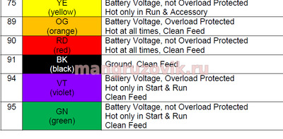
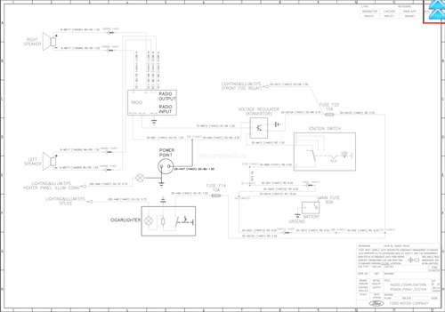
Ford Cargo Truck электрическая схема
Коммутация предохранителей и главного предохранителя.Подключение замка зажигания.Реле включения зажигания.Распределение цепей зажигания
Точки соединения массы (земли) в автомобиле. 
Ford Cargo Truck. Электрическая схема центрального замка.
На схеме указаны подключения к моторчикам замков в дверях, распиновка блока управления центральным замком, питающие предохранители.
Ford Cargo Truck Электрическая схема тормозной системы.
Распиновка блока управления ABS, датчики ABS, датчики тормозных колодок, ASR модуль, диагностический коннектор ABS, предохранители управления тормозной системой автомобиля Ford Cargo Truck.
Электрическая схема управления зеркалами заднего вида.
Подключение реле зеркал, коммутация предохранителей поворота зеркал и предохранителя подогрева зеркала, подключение кнопок управления зеркалами заднего вида, сервопривод (электродвигатель) управления зеркалом.
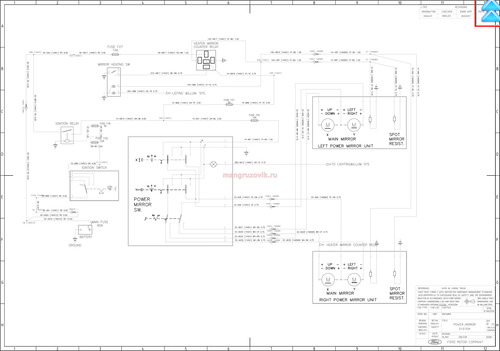
Электрическая схема освещения и звукового сигнала.
Схема подключения ближнего и дальнего света фар, противотуманных фар, задних противотуманок, габаритов, стояночных огней, поворотников, переключатель аварийной сигнализации (аварийки), стоп сигналов, фар заднего хода, корректор фар, цепь коммутации от главного предохранителя в аккумуляторном отсеке, предохранители освещения подсветки и освещения, схема соединения переключателя освещения и фар, схема коммутации реле фар, реле звукового сигнала, «лягушка» стоп-сигнала, освещение салона, подсветка приборной панели, соединение с замком зажигания.
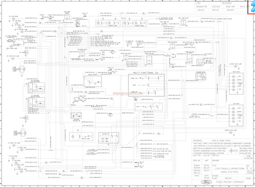
Электрическая схема стеклоподъемников.
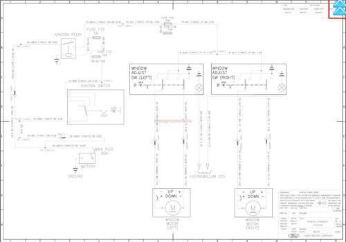
Электрическая схема стеклоочистителей лобового стекла и очистителей фар.
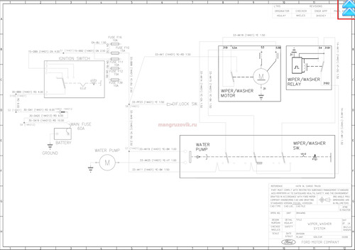
Электрическая схема штатного отопителя салона, кондиционера и дополнительного отопителя Вебасто (Webasto).
Электрическая схема подключения пульта управления Вебасто и схема подключения отопителя Webasto, подключение топливного насоса автономного отопителя Webasto, коммутация реле и предохранителей штатного и дополнительного отопителя, схема подключения переключателя многопозиционного штатного отопителя, подключение электромотора печки.
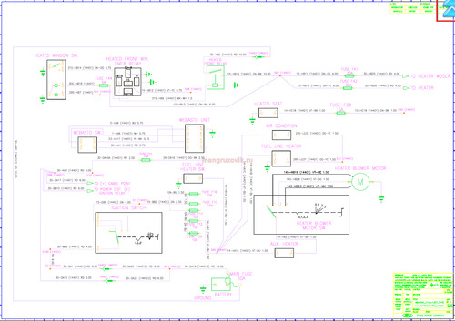
Электрическая схема штатного отопителя салона, кондиционера и дополнительного отопителя Эбешпехер (Eberspacher).
Электрическая схема подключения пульта управления Эбешпехер (Eberspacher) и схема подключения отопителя Эбешпехер (Eberspacher), подключение топливного насоса автономного отопителя Эбешпехер (Eberspacher), коммутация реле и предохранителей штатного и дополнительного отопителя, схема подключения переключателя многопозиционного штатного отопителя, подключение электромотора печки.
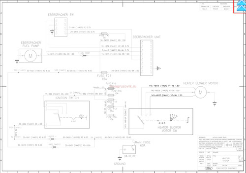
Электрическая схема приборной панели (щитка приборов),
Подключение указателя и датчика скорости, подключение тахографа, датчиков и указателей давления воздуха, подключение электронного табло служебной (текущей) информации, датчика и указателя уровня топлива в баке, распиновка коннекторов приборной доски, модуль подготовки воздуха, датчик и указатель температуры, датчики воды и масла, подключение реле зажигания и замка зажигания и прочее.
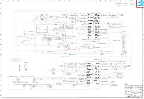
Распиновка разъемов на приборной панели автомобиля Ford Cargo Truck.
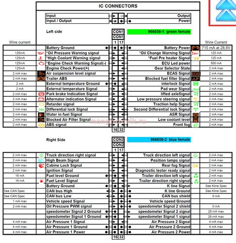
Электрическая схема управления двигателем.
Электросхема подключения генератора зарядки аккумуляторов, стартера, подключение замка зажигания, реле стартера, предохранителя зажигания, блока управления двигателем, подключение датчиков и селеноидов, вентилятора охлаждения, датчика положения коленвала, датчика положения распредвала, датчиков температуры и масла и прочее, соединение форсунок и топливного насоса.
схема 1 Электрическая схема управления двигателем.
схема 2 Электрическая схема управления двигателем.
схема 3 Электрическая схема управления двигателем.
схема 4 Электрическая схема управления двигателем.
схема 5 Электрическая схема управления двигателем.
Источник
На чтение 12 мин Просмотров 14 Опубликовано 8 апреля 2023 Обновлено 8 апреля 2023
Содержание
- Руководство по эксплуатации Ford Cargo
- Ford Cargo
- Назначение
- Технические характеристики
- Двигатели
- Коробка передач
- Шасси
- Подвеска
- Тормоза
- Рулевое
- Внешний вид и интерьер кабины
- Модификации
Руководство по эксплуатации Ford Cargo
Введение 3
Общие положения
Ключи 7
Запирание/отпирание дверей 7
Солнцезащитные козырьки 7
Капот 8
Зеркала 8
Вентиляционный люк в крыше кабины 8
Центральные аэраторы 8
Боковые аэраторы 9
Отсек для мелких предметов 9
Верхняя боковая консоль 9
Центральная консоль 9
Звукоизоляция 9
Подвеска кабины 10
Управление сиденьями 10
Откидывание кабины 11
Ремни безопасности 12
Верхняя койка 12
Двигатель 12
Приборы и органы управления
Указатели и органы управления 14
Аналоговый тахометр 14
Спидометр 14
Указатель уровня топлива 14
Указатель давления воздуха 15
Указатель температуры воды 15
Указатель давления масла 15
Тахограф 16
Контрольные лампы 16
Генераторы (предупреждение системы зарядки) 16
Контрольная лампа дальнего света фар 16
Контрольная лампа указателей поворота 16
Предупреждение о недостаточном давлении масла 16
Контрольная лампа стояночного тормоза 17
Контрольная лампа ASR 17
Контрольная лампа блокировки кабины 17
Контрольная лампа двигателя 17
Предупреждающий сигнал уровня охлаждающей жидкости 17
Контрольная лампа ABS 17
Контрольная лампа пневматической подвески 18
Переключатель системы регулировки тягового усилия (для автомобилей 6×2 с пневматической подвеской) 18
Контрольная лампа нормального уровня 18
Контрольная лампа температуры 18
Органы управления 19
Переключатель освещения 19
Центральные и боковые аэраторы 19
Отопитель 19
Система кондиционирования воздуха 20
Переключатель задних противотуманных огней 20
Выключатель внедорожного режима ASR 21
Аварийная сигнализация (мигающая световая сигнализация) 21
Переключатель блокировки дифференциала (при наличии) 21
Переключатель блокировки дифференциала вторичного ведущего моста (для автомобилей с приводом на 4 колеса) 21
Переключатель взаимной блокировки мостов (для автомобилей с приводом на 4 колеса) 21
Выключатель внедорожного режима ABS 22
Пепельница 22
Контрольная лампа гидроусилителя управления 22
Замок зажигания/блокиратор рулевой колонки 23
Многофункциональный подрулевой переключатель 23
Переключатель очистителя/омывателя лобового стекла 24
Освещение салона 24
Рычаг стояночного тормоза 24
Моторный тормоз-замедлитель 25
Ретардер (при наличии) 26
Рычаг ретардера 26
Механизм регулировки положения рулевого колеса 26
Коробка отбора мощности РТО 27
Центральный замок 28
Цифровой приборный щиток 29
Спидометр 29
Указатель давления воздуха 29
Температура наружного воздуха 29
Бортовой компьютер 29
Предупреждающие символы 29
Коды DTC 30
Управление автомобилем
Промежуточный теплообменник 31
Коробки передач 31
Разгрузка стояночного тормоза 32
Клапаны 33
Полностью пневматическая система 34
Индикаторы износа тормозных колодок 34
Четырех ходовой предохранительный клапан 35
Вспомогательная воздушная магистраль 35
Электронный блок управления ABS и опорная панель 35
Диагностический разъем 36
Клапаны регулировки давления 36
Система ASR 36
FORD CARGO 3230S — Ведущий мост c пневматической подвеской 36
Переключатели управления самонаправляемым мостом 37
Двигатель 38
Процедура запуска двигателя 38
Выключение двигателя 39
Работа турбокомпрессора 39
Главный топливный фильтр 39
Пневматическая система с электронным управлением 39
Электронный блок управления пневматической системой и опорная панель (для автомобилей с пневматической системой с четырьмя пневмобаллонами) 39
Электромагнитный клапан (для автомобилей с пневматической подвеской с четырьмя пневмобаллонами) 40
Блок ручного управления (для автомобилей с пневматической подвеской с четырьмя пневмобаллонами) 40
Подсоединение прицепа и полуприцепа 41
Плита опорно-сцепного устройства (CARGO 1830) 42
Сцепное устройство для прицепа (CARGO 2530) 42
Проверка и обслуживание сцепного устройства для прицепа (CARGO 2530) 43
Проверка и обслуживание сцепного устройства для полуприцепа (CARGO 1330) 43
Общие сведения о дополнительном отопителе 44
Блок сухого типа. Расход топлива 44
Использование дополнительного отопителя 44
Выключение отопителя 45
Неисправности 45
Профилактическое обслуживание 45
Техническое обслуживание
Ежедневные операции 46
Уровень масла в двигателе 46
Давление в шинах 46
Воздушные ресиверы 46
Осушитель воздуха 47
Уровень охлаждающей жидкости двигателя 47
Бачок стеклоомывателя 48
Световые приборы 48
Еженедельные операции 48
Бачок гидропривода выключения сцепления 48
Электронный индикатор воздушного фильтра 48
Датчик высоты 49
Воздушный фильтр в сборе 49
Основной элемент воздушного фильтра 49
Вспомогательный элемент воздушного фильтра 50
Ежемесячные операции 50
Циклонная крышка 50
Расход моторного масла 50
Топливный фильтр грубой очистки 51
Топливный бак 51
Крышка топливного бака (запираемая) 51
Проверки на автомобиле с пневматической подвеской с четырьмя пневмобаллонами 52
Смазка
Спецификации и заправочные объемы 53
Смазки, рекомендуемые для холодной и жаркой погоды 56
Экстренные ситуации
Обслуживание тормозных колодок 57
Запасное колесо 57
Подъем автомобиля домкратом 57
Буксировка автомобиля 58
Колесные диски и шины 59
Воздушные фильтры 60
Проверка уровня охлаждающей жидкости двигателя 60
Бачок рабочей жидкости усилителя рулевого управления 60
Замена масла в гидравлической системе рулевого управления 61
Замена фильтра бачка усилителя рулевого управления 61
Доливка охлаждающей жидкости и удаление воздуха из системы 61
Быстрое удаление оставшегося воздуха из системы 62
Зарядка аккумулятора 62
Запуск от вспомогательного аккумулятора 63
Замена ламп фар 64
Замена ламп стояночных фонарей 64
Замена ламп передних указателей поворота 64
Замена ламп габаритных фонарей, стоп-сигналов, фонарей заднего хода и противотуманных фонарей 65
Замены лампы подсветки номерного знака 65
Потолочный плафон 65
Замена ламп боковых повторителей указателей поворота 66
Замена лампы освещения салона 66
Замена ламп подсветки указателей, индикаторов и контрольных ламп 66
Замена контрольных ламп аварийной световой сигнализации и блокировки дифференциала 66
Основные предохранители 67
Плавкие предохранители 68
Возможные неисправности и их устранение 70
Технические данные Форд Карго
Двигатель ECOTOGQ 7,3 л/240 л.с 73
Двигатель ECOTOGQ 7,3 л/300 л.с 73
Задний мост 74
Коробка передач 75
РТО — Блок отбора мощности коробки передач 75
Геометрия передних мостов 76
Электрическая система 77
Идентификация 78
Паспортная табличка автомобиля 78
Паспортная табличка LAV 78
Номер шасси 78
Номер двигателя 78
Шины 79
Основные размеры 80
Модель 1824/1830. Грузовое шасси с дневной кабиной 80
Модель 1824. Грузовое шасси 81
Модель 1830. Грузовое шасси 82
Модель 2524/2530. Грузовое шасси с дневной кабиной 83
Модель 2524. Грузовое шасси с дневной кабиной 84
Модель 2530. Грузовое шасси 85
Модель 3230С. Грузовое шасси 86
Модель 3230S. Грузовое шасси 87
Модель 1824F/1830F. Грузовое шасси под полноразмерный трейлер 88
Модель 2530F. Грузовое шасси под полноразмерный трейлер 89
Модель 2524D/2530D. Шасси под самосвал 90
Модель 3430D. Внедорожное шасси под самосвал 91
Модель 1830Т. Седельный тягач 92
Модель 1824СС/1830СС. Шасси под автовоз 93
Источник
Ford Cargo
Ford Cargo – наиболее удачная серия грузовых автомобилей от американского производителя. Их выпуск начался еще в далеком 1982 году, когда на рынке впервые появились грузовики модели 1812. Изначально продажи стартовали в трех странах – Турции, Бразилии и Великобритании. Несмотря на финансовые проблемы компании, которые начались в 1997 году, серия грузовых автомобилей все также продолжалась выпускаться, причем сфера их продаж достигал Индии и США.
Автомобили предназначены для перевозки строительных, сельскохозяйственных и других материалов, либо каких-то других грузов большого тоннажа. Одной из наиболее удачных серий принято считать H298, который стал активно поставляться на территорию стран СНГ, начиная с 2007 года.
Назначение
Производитель Форд Карго предполагал создать универсальный тягач, для работы, как на строительных площадках, так и в городских условиях, либо на длительных межгородских дистанциях. Сначала автомобиль занял рынок своей страны, после чего за несколько лет вышел на Россию и страны СНГ. Здесь грузовик и самосвал оценили за соотношение цены и качества. Минусом использования этого автомобиля стала немного низкая эргономика кабины, а также отставание в технических возможностях от таких известных брендов, как Вольво, Мэн и Скания.

Самосвал Форд Карго
Презентовали модель грузовика Форд Карго в России в 2007 году. Это состоялось на выставке «Комтранс-2007». Тогда автомобиль стали называть возможной альтернативой замены более старых грузовиков и самосвалов для дорожно-эксплуатационных и строительных работ. С тех пор на дорогах отечественного пространства и появилась модель Карго, которая дословно переводится как «груз».
Ценовая политика компании Форд достаточно приемлема, поэтому автомобиль сумел занять средний диапазон стоимости, разместившись между дешевыми отечественными транспортными средствами и европейскими дорогими автомобилями.
Технические характеристики
|
|
Двигатели
| Варианты двигателей | Ecotorq 260 | Ecotorq 320 | Ecotorq 350 | Ecotorq 380 |
| Объем двигателя | Силовой агрегат с объемом в 7,3 литра | Силовой агрегат с объемом в 9 литров | Силовой агрегат с объемом в 9 литров | Силовой агрегат с объемом в 9 литров |
| Количество лошадиных сил | 260 единиц | 320 единиц | 350 единиц | 380 единиц |
| Крутящий момент | от 1200 до 1800 Н*м | от 1200 до 1800 Н*м | от 1200 до 1700 Н*м | от 1450 до 1600 Н*м |
| Евро-стандарты | Евро-3 | Евро-3 | Евро-3 | Евро-5 |
| Расход топлива | 35 л | З5 л | 38 л | 40 л |
| Колесная база | 4*2 | 6*2 | 6*4 | 8*2 |
В большинстве модификаций грузовика используются 6-цилиндровые двигатели, так как они наиболее надежны на длительных дистанциях. Литраж зависит напрямую от конкретно взятой модификации. Грузовик может быть 7-литровым, 9-литровым и 10-литровым. При этом, мощность самого мотора от 260 до 400 лошадиных сил.
На стадии разработки Ford Cargo, было уделено особое внимание сроку эксплуатации мотора, так как грузовик изначально был предназначен для перевозки крупногабаритных грузов. Следовательно, механизм обладает огромным ресурсом и способен демонстрировать свою надежность вне зависимости от тоннажа, дороги, расстояния езды и других возможных факторов.
Коробка передач
Практически во всех модификациях автомобилей задействуется именно 12-ступенчатая коробка передач на автоматизированной основе (ZF As-Tronic). При желании, водитель Форд Карго может использовать ее и в ручном режиме, если так ему более удобно. Тем более, как уже ранее отмечалось, есть возможность переключения передачи сразу на 2 пункта, что значительно упрощает управление данным видом транспорта.
Шасси
Учитывая сферу использования грузовика, который задействуется при перевозке грузов повышенного тоннажа, применили усиленное шасси из ниобиевого сплава. Таким образом, удалось значительно повысить грузоподъемность платформы и сделать автомобиль более надежным при езде в условиях повышенного уровня сложности.
Подвеска
Задняя подвеска представляет собой основную параболическую рессору, которая включает в себя несколько амортизаторов, повышающих устойчивость на дороге и улучшающих баланс между шасси и кузовом. Задняя подвеска состоит из многолистовых рессор, c поперечными стабилизаторами, за счет которых и образуется вся конструкция шасси.
Тормоза
Тормозная система грузовика так же относится к числу его явных плюсов, так как выполнена профессионалами своего дела и отлично проявляет себя при большом морозе, не выдавая никаких сбоев. Чтобы уменьшить тормозной путь Форд Карго, были использованы пневматические двухконтурные тормозные диски Z-типа. Кроме этого, в тормозной комплекс так же входит специальный подогреватель с ярко выраженным маслоотделителем и ретардером. Все эти элементы принимают прямое участие в торможении грузовика.
Рулевое
Основным компонентом в рулевой системе является механизм Hema ZF 8098 servocom, который считается одной из наиболее надежных рулевых систем на данный момент. Рулевое колесо Ford Cargo предельно точно синхронизировано с колесами, за счет чего управление грузовиком является максимально точным. Кроме этого, рулевой механизм включает в себя еще и гидроусилитель руля, который упрощает процесс управления, делая его более удобным и приятным.
Внешний вид и интерьер кабины
Кабина Форд Карго является достаточно компактной по своим габаритам. При этом в ней присутствуют специальные боковые отсеки, являющиеся вполне вместительными и удобными для таких размеров машины. Рабочая зона в автомобиле является минималистической, обладая лишь самыми важными функциональными особенностями. Поручни на входе, а также ручки люка не являются ничем обшитыми, из-за чего при значительных морозах это вызывает некоторые неудобства.
Стекла оснащены в Ford Cargo электроподъемниками, которые размещены в центре приборной панели, а не на самой двери. Непосредственно вблизи с ними расположен механизм регулировки зеркал заднего вида.
Спальные места в Ford Cargo также есть – они размещены непосредственно за передними сидениями. Их габаритные размеры являются вполне удобным. Оба ни в длину составляют 190 сантиметр при ширине в 67 и 58 сантиметров.
В центральной части приборной панели на Ford Cargo установлен небольшой бортовой компьютер. Для того чтобы водитель мог удобно хранить вещи, оборудованы несколько отсеков в верхней части кабины. Возле рычага коробки переключения передач находятся подстаканники.
Описание кабины Ford Cargo в целом является достаточно удобным. Грузовик пытается стать аналогом своих европейских конкурентов, лишь немного уступая им в некоторых вещах.
Модификации
Говоря в целом, модельный ряд грузовиков более чем велик, в него можно включить более 10 модификаций Ford Cargo. Определенные модели не имели каких-то весомых отличий, так как в них совершенствовались лишь самые проблемные моменты, из-за чего нет смысла перечислять каждую модификацию. Мы же выделим наиболее часто встречающиеся серии грузовиков, которые действительно технологичны.
H298 – одна из первых удачных серийных моделей, которые могут весить от 16 до 60 тонн. Модификация делится на 4 основные категории:
- Тягачи. Чаще всего используются для осуществления перевозок на международном уровне;
- Тяжелые развозные грузовики. Применяются для перевозок в пригородах, либо прямиком в пределах города. Их особенностью в упрощенной конструкции, которая делает езду более простой и комфортной;
- Форд Карго с повышенной грузоподъемностью. Категория подразумевает усиление всей конструкции автомобиля, начиная с рамной части и заканчивая мостами соединения;
- Грузовики строительного типа. Такие автомобили выступают в роли самосвалов, бетоносмесителей, и других модификаций, которые активно применяются в строительной отрасли.
За основу серии Ford Cargo H298 изначально берется 6-цилиндровый двигатель, объем которого равен 7.33 литра. (240/300 л.с.)
H476 – за силовые показатели грузовиков серии отвечают турбированные дизельные двигатели объемом 7.3 либо 9 литров. Первая версия работает с 260 лошадиными силами на борту. В случае с 9-литровым силовым агрегатом, количество лошадиных сил разное: 320, 350 и 380 включительно. В зависимости от конкретно взятой модификации, может отличаться так же и емкость бака, который вмещает от 300 до 650 литров топлива. Потребляет грузовик от 30 до 40 литров на 100 километров.
Форд Карго H566 – это одна из новейших модификаций, которая изначально оснащена 10-литровым двигателем на дизельной основе, мощность которого равна 460 л.с. В продаже есть две вариации грузовика, с 12-ступенчатой коробкой передач, так и с 16-ступенчатой. Переключать передачи можно как по одной, так и сразу две, в зависимости от участка дороги и скорости которую сможет развить автомобиль.
Источник
We have 41 Ford
Cargo manuals
covering a total of 36 years of production.
In the table below you can see 1
Cargo Workshop Manuals,0
Cargo Owners Manuals and 10 Miscellaneous
Ford Cargo downloads.
Our most popular manual is the
Ford — Cargo — Parts Catalogue — 2016 — 2016
.
This (like all of our manuals) is available to download for free in PDF format.
How to download a Ford Cargo
Repair Manual (for any year)
These Cargo manuals have been provided by our users,
so we can’t guarantee completeness. We’ve checked the years that the manuals cover
and we have Ford Cargo repair manuals
for the following years; 1981, 1982, 1988, 1994, 1995, 1996, 2003, 2007, 2009, 2010, 2011, 2012, 2014, 2015, 2016 and 2017.
Go through the 41 different PDF’s that are displayed below,
for example this one. You’ll then be shown the first 10 pages of this specific
document, you can then scroll down and click ‘show full PDF’. Then you can click
download you’ve got a totally free car manual, forever!
What topics does the Ford Cargo
Service/Repair Manual cover?
In total, that’s over 2259 pages of content dedicated to your
Ford Cargo. Here’s a non exhaustive list
of what’s covered;
- Ford Cargo service manual for roadside repairs
- Ford Cargo owners manual covering weekly checks
- Ford Cargo workshop manual covering Lubricants, fluids and tyre pressures
- Ford Cargo service PDF’s covering routine maintenance and servicing
- Detailed Ford Cargo Engine and Associated Service Systems (for Repairs and Overhaul) (PDF)
- Ford Cargo Transmission data Service Manual PDF
- Ford Cargo Brakes and suspension PDF
- Ford Cargo Wiring Diagrams
Looking for a Free Ford Cargo Haynes /
Ford Cargo Chilton Manuals?
We get a lot of people coming to the site looking to get themselves a free
Ford Cargo Haynes
manual. There are two things you need to know; firstly it’s illegal, and secondly —
there are much better ways of servicing and understanding your
Ford Cargo engine than
the Haynes manual. That’s essentially what we’re here for — to give you an
alternative to the Haynes and Chilton, online and totally for free.
Show more
Show less


