- Manuals
- Brands
- Mitsubishi Electric Manuals
- Inverter
- FR-D740-012
Manuals and User Guides for Mitsubishi Electric FR-D740-012. We have 2 Mitsubishi Electric FR-D740-012 manuals available for free PDF download: Instruction Manual, Installation Manuallines
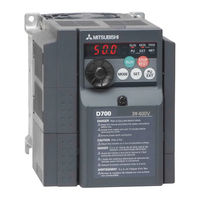
Mitsubishi Electric FR-D740-012 Instruction Manual (296 pages)
Brand: Mitsubishi Electric
|
Category: Inverter
|
Size: 16.8 MB
Table of Contents
-
Instruction Manual
1
-
Table of Contents
5
-
1 Outline
13
-
Product Checking and Parts Identification
13
-
Inverter and Peripheral Devices
14
-
Specifications
14
-
Peripheral Devices
15
-
-
Removal and Reinstallation of the Cover
16
-
Front Cover
16
-
Wiring Cover
18
-
Wiring
18
-
-
Installation of the Inverter and Enclosure Design
19
-
Inverter Installation Environment
19
-
Cooling System Types for Inverter Enclosure
21
-
Inverter Placement
22
-
-
-
2 Wiring
24
-
Terminal Connection Diagram
25
-
Main Circuit Terminal Specifications
26
-
Specification of Main Circuit Terminal
26
-
Terminal Arrangement of the Main Circuit Terminal, Power Supply and the Motor Wiring
26
-
Cables and Wiring Length
28
-
Main Circuit Terminal Specifications
29
-
-
Control Circuit Specifications
31
-
Control Circuit Terminal
31
-
Changing the Control Logic
33
-
Connection of Stand-Alone Option Unit
34
-
Wiring of Control Circuit
35
-
Wiring Instructions
38
-
Connection to the PU Connector
39
-
-
Connection of Stand-Alone Option Unit
41
-
(MRS Type, MYS Type, FR-ABR) (FR-D720-025 or More, FR-D740-012 or More, FR
41
-
Connection of the Brake Unit (FR-BU2)
43
-
Connection of the High Power Factor Converter (FR-HC)
44
-
Connection of the Power Regeneration Common Converter (FR-CV)
45
-
Connection of a DC Reactor (FR-HEL)
45
-
-
-
3 Precautions for Use of the Inverter
46
-
EMC and Leakage Currents
47
-
Leakage Currents and Countermeasures
47
-
Inverter-Driven 400V Class Motor
47
-
EMC Measures
49
-
Power Supply Harmonics
51
-
Installation of Power Factor Improving Reactor
52
-
Power-Off and Magnetic Contactor (MC)
53
-
Inverter-Driven 400V Class Motor
54
-
Precautions for Use of the Inverter
55
-
Failsafe of the System Which Uses the Inverter
57
-
-
4 Parameters
60
-
Operation Panel
61
-
Names and Functions of the Operation Panel
61
-
Basic Operation (Factory Setting)
62
-
Easy Operation Mode Setting (Easy Setting Mode)
63
-
Change the Parameter Setting Value
64
-
Setting Dial Push
64
-
-
Parameter List
65
-
Adjust the Output Torque (Current) of the Motor
75
-
Manual Torque Boost (Pr. 0, Pr. 46)
75
-
Large Starting Torque and Low Speed Torque Are Necessary (General-Purpose Magnetic Flux Vector Control (Pr. 71, Pr. 80))
77
-
Test Run
78
-
Slip Compensation (Pr. 245 to Pr. 247)
80
-
Stall Prevention Operation (Pr. 22, Pr. 23, Pr. 48, Pr. 66, Pr. 156, Pr. 157)
81
-
-
Limit the Output Frequency
85
-
Maximum/Minimum Frequency (Pr. 1, Pr. 2, Pr. 18)
85
-
Avoid Mechanical Resonance Points (Frequency Jumps) (Pr. 31 to Pr. 36)
86
-
-
Set V/F Pattern
87
-
Base Frequency, Voltage (Pr. 3, Pr. 19, Pr. 47)
87
-
Load Pattern Selection (Pr. 14)
89
-
-
Frequency Setting by External Terminals
91
-
Operation by Multi-Speed Operation (Pr. 4 to Pr. 6, Pr. 24 to Pr. 27, Pr. 232 to Pr. 239)
91
-
Jog Operation (Pr. 15, Pr. 16)
93
-
Remote Setting Function (Pr. 59)
95
-
-
Setting of Acceleration/Deceleration Time and Acceleration/ Deceleration Pattern
98
-
Setting of the Acceleration and Deceleration Time (Pr. 7, Pr. 8, Pr. 20, Pr. 44, Pr. 45)
98
-
Starting Frequency and Start-Time Hold Function (Pr. 13, Pr. 571)
100
-
Acceleration/Deceleration Pattern (Pr. 29)
101
-
-
Selection and Protection of a Motor
102
-
Motor Overheat Protection (Electronic Thermal O/L Relay, PTC Thermistor Protection) (Pr. 9, Pr. 51, Pr. 561)
102
-
Applied Motor (Pr. 71, Pr. 450)
105
-
To Exhibit the Best Performance of the Motor (Offline Auto Tuning) (Pr. 71, Pr. 80, Pr. 82 to Pr. 84, Pr. 90, Pr. 96)
107
-
-
Motor Brake and Stop Operation
111
-
DC Injection Brake (Pr. 10 to Pr. 12)
111
-
Selection of a Regenerative Brake (Pr. 30, Pr. 70)
112
-
Stop Selection (Pr. 250)
114
-
-
Function Assignment of External Terminal and Control
115
-
Input Terminal Function Selection (Pr. 178 to Pr. 182)
115
-
Inverter Output Shutoff Signal (MRS Signal, Pr. 17)
117
-
Condition Selection of Function Validity by Second Function Selection Signal (RT)
118
-
Start Signal Operation Selection (STF, STR, STOP Signal, Pr. 250)
119
-
Output Terminal Function Selection (Pr. 190, Pr. 192)
121
-
Detection of Output Frequency (SU, FU Signal, Pr. 41 to Pr. 43)
125
-
Output Current Detection Function (Y12 Signal, Y13 Signal, Pr. 150 to Pr. 153, Pr. 166, Pr. 167)
126
-
Remote Output Selection (REM Signal, Pr. 495, Pr. 496)
128
-
-
Monitor Display and Monitor Output Signal
129
-
Speed Display and Speed Setting (Pr. 37)
129
-
Monitor Display Selection of Operation Panel/Pu and Terminal am (Pr. 52, Pr.158, Pr. 170, Pr. 171, Pr. 268, Pr. 563, Pr. 564, Pr. 891)
130
-
Reference of the Terminal am (Analog Voltage Output) (Pr. 55, Pr. 56)
135
-
Terminal am Calibration (Calibration Parameter C1 (Pr.901))
136
-
-
Operation Selection at Power Failure and Instantaneous Power Failure
138
-
Automatic Restart after Instantaneous Power Failure/Flying Start (Pr. 30, Pr. 57, Pr. 58, Pr. 96, Pr. 162, Pr. 165, Pr. 298, Pr. 299, Pr. 611)
138
-
Power-Failure Deceleration Stop Function (Pr. 261)
144
-
-
Operation Setting at Fault Occurrence
146
-
Retry Function (Pr. 65, Pr. 67 to Pr. 69)
146
-
Input/Output Phase Loss Protection Selection (Pr. 251, Pr. 872)
148
-
-
Earth (Ground) Fault Detection at Start (Pr. 249)
148
-
-
-
Energy Saving Operation
149
-
Optimum Excitation Control (Pr. 60)
149
-
-
Motor Noise, EMI Measures, Mechanical Resonance
150
-
PWM Carrier Frequency and Soft-PWM Control (Pr. 72, Pr. 240, Pr. 260)
150
-
Speed Smoothing Control (Pr. 653)
151
-
-
Frequency Setting by Analog Input (Terminal 2, 4)
152
-
Analog Input Selection (Pr. 73, Pr. 267)
152
-
Response Level of Analog Input and Noise Elimination (Pr. 74)
154
-
Bias and Gain of Frequency Setting Voltage (Current) (Pr. 125, Pr. 126, Pr. 241, C2 (Pr. 902) to C7 (Pr. 905))
155
-
-
Misoperation Prevention and Parameter Setting Restriction
160
-
Reset Selection/Disconnected PU Detection/Pu Stop Selection (Pr. 75)
160
-
Parameter Write Disable Selection (Pr. 77)
163
-
Reverse Rotation Prevention Selection (Pr. 78)
164
-
Extended Parameter Display (Pr. 160)
164
-
Password Function (Pr. 296, Pr. 297)
165
-
-
Selection of Operation Mode and Operation Location
167
-
Operation Mode Selection (Pr. 79)
167
-
Operation Mode at Power-On (Pr. 79, Pr. 340)
177
-
Start Command Source and Frequency Command Source During Communication Operation (Pr. 338, Pr. 339, Pr. 551)
178
-
-
Communication Operation and Setting
182
-
Wiring and Configuration of PU Connector
182
-
Initial Settings and Specifications of RS-485 Communication (Pr. 117 to Pr. 120, Pr. 123, Pr. 124, Pr. 549)
185
-
Operation Selection at Communication Error Occurrence (Pr. 121, Pr. 122, Pr. 502)
186
-
Communication EEPROM Write Selection (Pr. 342)
189
-
Mitsubishi Inverter Protocol (Computer Link Communication)
190
-
Run Command
200
-
Modbus RTU Communication Specifications (Pr. 117, Pr. 118, Pr. 120, Pr. 122, Pr. 343, Pr. 502, Pr. 549)
202
-
-
Special Operation and Frequency Control
214
-
PID Control (Pr. 127 to Pr. 134, Pr. 575 to Pr. 577)
214
-
Dancer Control (Pr. 44, Pr. 45, Pr. 128 to Pr. 134)
222
-
Regeneration Avoidance Function (Pr. 665, Pr. 882, Pr. 883, Pr. 885, Pr. 886)
228
-
-
Useful Functions
230
-
Cooling Fan Operation Selection (Pr. 244)
230
-
Display of the Life of the Inverter Parts (Pr. 255 to Pr. 259)
231
-
Maintenance Timer Alarm (Pr. 503, Pr. 504)
235
-
Current Average Value Monitor Signal (Pr. 555 to Pr. 557)
236
-
Free Parameter (Pr. 888, Pr. 889)
238
-
-
Setting the Parameter Unit and Operation Panel
239
-
RUN Key Rotation Direction Selection (Pr. 40)
239
-
PU Display Language Selection(Pr.145)
239
-
Operation Panel Frequency Setting/Key Lock Operation Selection (Pr. 161)
240
-
Magnitude of Frequency Change Setting (Pr. 295)
242
-
Buzzer Control (Pr. 990)
243
-
PU Contrast Adjustment (Pr. 991)
243
-
-
Parameter Clear/ All Parameter Clear
244
-
Initial Value Change List
245
-
Check and Clear of the Faults History
246
-
-
5 Troubleshooting
249
-
Reset Method of Protective Function
250
-
List of Fault or Alarm Indications
251
-
Causes and Corrective Actions
252
-
Correspondences between Digital and Actual Characters
261
-
Check First When You Have some Troubles
262
-
Motor Does Not Start
262
-
Motor or Machine Is Making Abnormal Acoustic Noise
264
-
Inverter Generates Abnormal Noise
265
-
Motor Generates Heat Abnormally
265
-
Motor Rotates in the Opposite Direction
265
-
Speed Greatly Differs from the Setting
265
-
Acceleration/Deceleration Is Not Smooth
266
-
Speed Varies During Operation
266
-
Operation Mode Is Not Changed Properly
267
-
Operation Panel Display Is Not Operating
267
-
Motor Current Is too Large
267
-
Speed Does Not Accelerate
268
-
Unable to Write Parameter Setting
268
-
-
-
6 Precautions for Maintenance and Inspection
270
-
Inspection Items
270
-
Daily Inspection
270
-
Periodic Inspection
270
-
Daily and Periodic Inspection
271
-
Display of the Life of the Inverter Parts
272
-
Checking the Inverter and Converter Modules
273
-
Cleaning
274
-
Replacement of Parts
274
-
Measurement of Main Circuit Voltages, Currents and Powers
278
-
Measurement of Powers
280
-
Measurement of Voltages and Use of PT
280
-
Measurement of Currents
281
-
Use of CT and Transducer
281
-
Measurement of Inverter Input Power Factor
281
-
Measurement of Converter Output Voltage (Across Terminals P and N)
281
-
Insulation Resistance Test Using Megger
282
-
Pressure Test
282
-
-
-
7 Specifications
283
-
Rating
284
-
Common Specifications
286
-
Outline Dimension Drawings
287
-
-
Appendix
291
-
Appendix1 Index
292
-
-
Advertisement

Mitsubishi Electric FR-D740-012 Installation Manuallines (30 pages)
Brand: Mitsubishi Electric
|
Category: Inverter
|
Size: 2.61 MB
Table of Contents
-
Table of Contents
1
-
Product Checking and Parts Identification
4
-
Outline Dimension Drawings
6
-
Terminal Connection Diagram
7
-
Main Circuit
7
-
Control Circuit
7
-
-
Wiring
7
-
Main Circuit Terminal Specifications
8
-
Cables and Wiring Length
10
-
Control Circuit Specifications
13
-
-
Precautions for Use of the Inverter
15
-
Failsafe of the System Which Uses the Inverter
17
-
Parameter List
18
-
Troubleshooting
22
-
List of Fault or Alarm Indications
23
-
Appendix 2 Instructions for Ul and Cul
27
-
Motor Overload Protection
27
-
Advertisement
Related Products
-
Mitsubishi Electric FR-D740-0.4K
-
Mitsubishi Electric FR-D740-012SC
-
Mitsubishi Electric FR-D740-0.75K
-
Mitsubishi Electric FR-D740-012-EC
-
Mitsubishi Electric FR-D740-022-EC
-
Mitsubishi Electric FR-D740-036-EC
-
Mitsubishi Electric FR-D740-050-EC
-
Mitsubishi Electric FR-D740-080-EC
-
Mitsubishi Electric FR-D740-7.5K-EA
-
Mitsubishi Electric FR-D740-15K
Mitsubishi Electric Categories
![]()
Air Conditioner
Controller
![]()
Projector
Inverter
Heat Pump
More Mitsubishi Electric Manuals
- Manuals
- Brands
- Mitsubishi Electric Manuals
- Inverter
- FR-D740-2.2K
Manuals and User Guides for Mitsubishi Electric FR-D740-2.2K. We have 2 Mitsubishi Electric FR-D740-2.2K manuals available for free PDF download: Instruction Manual
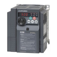
Mitsubishi Electric FR-D740-2.2K Instruction Manual (313 pages)
Brand: Mitsubishi Electric
|
Category: Inverter
|
Size: 15.06 MB
Table of Contents
-
Table of Contents
4
-
1 Outline
11
-
Product Checking and Parts Identification
11
-
Inverter and Peripheral Devices
12
-
Peripheral Devices
13
-
-
Removal and Reinstallation of the Cover
14
-
Front Cover
14
-
Wiring Cover
16
-
Wiring
16
-
-
Installation of the Inverter and Enclosure Design
17
-
Inverter Installation Environment
17
-
Cooling System Types for Inverter Enclosure
19
-
Inverter Placement
20
-
-
-
2 Wiring
22
-
Terminal Connection Diagram
23
-
Main Circuit Terminal Specifications
24
-
Specification of Main Circuit Terminal
24
-
Terminal Arrangement of the Main Circuit Terminal, Power Supply and the Motor Wiring
24
-
Cables and Wiring Length
26
-
-
Control Circuit Specifications
29
-
Control Circuit Terminal
29
-
Changing the Control Logic
31
-
Wiring of Control Circuit
33
-
Connection of Stand-Alone Option Unit
33
-
Safety Stop Function
36
-
Connection to the PU Connector
38
-
-
Connection of Stand-Alone Option Unit
40
-
Connection of a Dedicated External Brake Resistor (MRS Type, MYS Type, FR-ABR)
40
-
Connection of the Brake Unit (FR-BU2)
42
-
Connection of the High Power Factor Converter (FR-HC)
43
-
Connection of the Power Regeneration Common Converter (FR-CV)
44
-
Connection of a DC Reactor (FR-HEL)
44
-
-
-
3 Precautions for Use of the Inverter
46
-
EMC and Leakage Currents
47
-
Leakage Currents and Countermeasures
47
-
Installation of Power Factor Improving Reactor
47
-
EMC Measures
49
-
Precautions for Use of the Inverter
50
-
Power Supply Harmonics
51
-
Harmonic Suppression Guideline in Japan
52
-
-
Installation of Power Factor Improving Reactor
54
-
Power-OFF and Magnetic Contactor (MC)
55
-
Inverter-Driven 400V Class Motor
56
-
Precautions for Use of the Inverter
57
-
Failsafe of the System Which Uses the Inverter
59
-
-
4 Parameters
62
-
Operation Panel
63
-
Names and Functions of the Operation Panel
63
-
Basic Operation (Factory Setting)
64
-
Easy Operation Mode Setting (Easy Setting Mode)
65
-
Changing the Parameter Setting Value
66
-
Displaying the Set Frequency
66
-
-
Parameter List
67
-
Adjustment of the Output Torque (Current) of the Motor
77
-
Manual Torque Boost (Pr. 0, Pr. 46)
77
-
Acquiring Large Starting Torque and Low Speed Torque (General-Purpose Magnetic Flux Vector Control (Pr. 71, Pr. 80))
78
-
Slip Compensation (Pr. 245 to Pr. 247)
81
-
Stall Prevention Operation (Pr. 22, Pr. 23, Pr. 48, Pr. 66, Pr. 156, Pr. 157)
82
-
-
Limiting the Output Frequency
86
-
Maximum/Minimum Frequency (Pr. 1, Pr. 2, Pr. 18)
86
-
Avoiding Mechanical Resonance Points (Frequency Jumps) (Pr. 31 to Pr. 36)
87
-
-
V/F Pattern
88
-
Base Frequency, Voltage (Pr. 3, Pr. 19, Pr. 47)
88
-
Load Pattern Selection (Pr. 14)
90
-
-
Frequency Setting by External Terminals
92
-
Operation by Multi-Speed Operation (Pr. 4 to Pr. 6, Pr. 24 to Pr. 27, Pr. 232 to Pr. 239)
92
-
Jog Operation (Pr. 15, Pr. 16)
94
-
Remote Setting Function (Pr. 59)
96
-
-
Setting of Acceleration/Deceleration Time and Acceleration/ Deceleration Pattern
99
-
Setting of the Acceleration and Deceleration Time (Pr. 7, Pr. 8, Pr. 20, Pr. 44, Pr. 45)
99
-
Starting Frequency and Start-Time Hold Function (Pr. 13, Pr. 571)
101
-
Acceleration/Deceleration Pattern (Pr. 29)
102
-
-
Selection and Protection of a Motor
103
-
Motor Overheat Protection (Electronic Thermal O/L Relay, PTC Thermistor Protection) (Pr. 9, Pr. 51, Pr. 561)
103
-
Applied Motor (Pr. 71, Pr. 450)
106
-
Exhibiting the Best Performance for the Motor (Offline Auto Tuning) (Pr. 71, Pr. 80, Pr. 82 to Pr. 84, Pr. 90, Pr. 96)
108
-
-
Motor Brake and Stop Operation
112
-
DC Injection Brake (Pr. 10 to Pr. 12)
112
-
Selection of a Regenerative Brake (Pr. 30, Pr. 70)
113
-
Stop Selection (Pr. 250)
115
-
-
Function Assignment of External Terminal and Control
116
-
Input Terminal Function Selection (Pr. 178 to Pr. 182)
116
-
Inverter Output Shutoff Signal (MRS Signal, Pr. 17)
118
-
Condition Selection of Function Validity by Second Function Selection Signal (RT)
119
-
Start Signal Operation Selection (STF, STR, STOP Signal, Pr. 250)
120
-
Output Terminal Function Selection (Pr. 190, Pr. 192, Pr. 197)
122
-
Detection of Output Frequency (SU, FU Signal, Pr. 41 to Pr. 43)
126
-
Output Current Detection Function (Y12 Signal, Y13 Signal, Pr. 150 to Pr. 153, Pr. 166, Pr. 167)
127
-
Remote Output Selection (REM Signal, Pr. 495, Pr. 496)
129
-
-
Monitor Display and Monitor Output Signal
130
-
Speed Display and Speed Setting (Pr. 37)
130
-
Monitor Display Selection of DU/PU and Terminal FM (Pr. 52, Pr. 54, Pr. 170, Pr. 171, Pr. 268, Pr. 563, Pr. 564, Pr. 891)
131
-
Reference of the Terminal FM (Pulse Train Output) (Pr. 55, Pr. 56)
136
-
Terminal FM Calibration (Calibration Parameter C0 (Pr. 900))
137
-
-
Operation Selection at Power Failure and Instantaneous Power Failure
139
-
Automatic Restart after Instantaneous Power Failure/Flying Start (Pr. 30, Pr. 57, Pr. 58, Pr. 96, Pr. 162, Pr. 165, Pr. 298, Pr. 299, Pr. 611)
139
-
Power-Failure Deceleration Stop Function (Pr. 261)
145
-
-
Operation Setting at Fault Occurrence
147
-
Retry Function (Pr. 65, Pr. 67 to Pr. 69)
147
-
Input/Output Phase Loss Protection Selection (Pr. 251, Pr. 872)
149
-
Earth (Ground) Fault Detection at Start (Pr. 249)
149
-
-
Energy Saving Operation
150
-
Optimum Excitation Control (Pr. 60)
150
-
-
Motor Noise, EMI Measures, Mechanical Resonance
151
-
PWM Carrier Frequency and Soft-PWM Control (Pr. 72, Pr. 240, Pr. 260)
151
-
Speed Smoothing Control (Pr. 653)
152
-
-
Frequency Setting by Analog Input (Terminal 2, 4)
153
-
Analog Input Selection (Pr. 73, Pr. 267)
153
-
Response Level of Analog Input and Noise Elimination (Pr. 74)
155
-
Bias and Gain of Frequency Setting Voltage (Current) (Pr. 125, Pr. 126, Pr. 241, C2 (Pr. 902) to C7 (Pr. 905))
156
-
-
Misoperation Prevention and Parameter Setting Restriction
161
-
Reset Selection/Disconnected PU Detection/Pu Stop Selection (Pr. 75)
161
-
Parameter Write Disable Selection (Pr. 77)
164
-
Reverse Rotation Prevention Selection (Pr. 78)
165
-
Extended Parameter Display (Pr. 160)
165
-
Password Function (Pr. 296, Pr. 297)
166
-
-
Selection of Operation Mode and Operation Location
168
-
Operation Mode Selection (Pr. 79)
168
-
Operation Mode at Power-ON (Pr. 79, Pr. 340)
168
-
Operation Mode at Power-ON (Pr. 79, Pr. 340)
176
-
Start Command Source and Frequency Command Source During Communication Operation (Pr. 338, Pr. 339, Pr. 551)
177
-
-
Communication Operation and Setting
181
-
Wiring and Configuration of PU Connector
181
-
Initial Settings and Specifications of RS-485 Communication (Pr. 117 to Pr. 120, Pr. 123, Pr. 124, Pr. 549)
184
-
Operation Selection at Communication Error Occurrence (Pr. 121, Pr. 122, Pr. 502)
185
-
Communication EEPROM Write Selection (Pr. 342)
188
-
Mitsubishi Inverter Protocol (Computer Link Communication)
189
-
Modbus-RTU Communication Specifications (Pr. 117, Pr. 118, Pr. 120, Pr. 122, Pr. 343, Pr. 502, Pr. 549)
201
-
Modbus-RTU Communication Specifications
201
-
-
Special Operation and Frequency Control
213
-
PID Control (Pr. 127 to Pr. 134, Pr. 575 to Pr. 577)
213
-
Dancer Control (Pr. 44, Pr. 45, Pr. 128 to Pr. 134)
221
-
Regeneration Avoidance Function (Pr. 665, Pr. 882, Pr. 883, Pr. 885, Pr. 886)
227
-
-
Useful Functions
229
-
Cooling Fan Operation Selection (Pr. 244)
229
-
Display of the Lives of the Inverter Parts (Pr. 255 to Pr. 259)
230
-
Maintenance Timer Alarm (Pr. 503, Pr. 504)
234
-
Current Average Value Monitor Signal (Pr. 555 to Pr. 557)
235
-
Free Parameter (Pr. 888, Pr. 889)
237
-
-
Setting the Parameter Unit and Operation Panel
238
-
RUN Key Rotation Direction Selection (Pr. 40)
238
-
PU Display Language Selection (Pr.145)
238
-
Operation Panel Frequency Setting/Key Lock Selection (Pr. 161)
239
-
Magnitude of Frequency Change Setting (Pr. 295)
241
-
Buzzer Control (Pr. 990)
242
-
PU Contrast Adjustment (Pr. 991)
242
-
-
E500 Series Operation Panel (PA02) Setting
243
-
Built-In Potentiometer Switching (Pr. 146)
243
-
Bias and Gain of the Built-In Frequency Setting Potentiometer (C22 (Pr. 922) to C25 (Pr. 923))
244
-
-
Parameter Clear/ All Parameter Clear
250
-
Initial Value Change List
251
-
Check and Clear of the Faults History
252
-
-
-
5 Troubleshooting
255
-
Reset Method of Protective Function
256
-
List of Fault or Alarm Indications
257
-
Causes and Corrective Actions
258
-
Correspondences between Digital and Actual Characters
267
-
Check First When You Have a Trouble
268
-
Motor Does Not Start
268
-
Motor or Machine Is Making Abnormal Acoustic Noise
270
-
Inverter Generates Abnormal Noise
271
-
Motor Generates Heat Abnormally
271
-
Motor Rotates in the Opposite Direction
271
-
Speed Greatly Differs from the Setting
271
-
Acceleration/Deceleration Is Not Smooth
272
-
Speed Varies During Operation
272
-
Operation Mode Is Not Changed Properly
273
-
Operation Panel Display Is Not Operating
273
-
Motor Current Is too Large
273
-
Speed Does Not Accelerate
274
-
Unable to Write Parameter Setting
274
-
-
-
6 Precautions for Maintenance and Inspection
276
-
Inspection Items
276
-
Daily Inspection
276
-
Periodic Inspection
276
-
Daily and Periodic Inspection
277
-
Display of the Life of the Inverter Parts
278
-
Checking the Inverter and Converter Modules
279
-
Cleaning
280
-
Replacement of Parts
280
-
-
Measurement of Main Circuit Voltages, Currents and Powers
284
-
Measurement of Powers
286
-
Measurement of Voltages and Use of PT
286
-
Measurement of Currents
287
-
Use of CT and Transducer
287
-
Measurement of Inverter Input Power Factor
287
-
Measurement of Converter Output Voltage (Across Terminals P/+ and N/-)
287
-
Measurement of Inverter Output Frequency
287
-
Insulation Resistance Test Using Megger
288
-
Pressure Test
288
-
-
-
7 Specifications
289
-
Rating
290
-
Common Specifications
292
-
Outline Dimension Drawings
293
-
-
Appendix
297
-
Appendix1 for Customers Replacing the Conventional Model with this Inverter
298
-
Appendix 1-1 Replacement of the FR-S500 Series
298
-
Appendix2 Specification Change Check
300
-
Appendix 2-1 Changed Function
300
-
Appendix3 Index
301
-
Advertisement
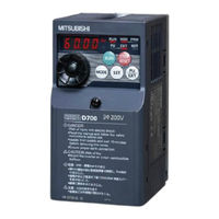
Mitsubishi Electric FR-D740-2.2K Instruction Manual (60 pages)
Brand: Mitsubishi Electric
|
Category: Inverter
|
Size: 4.54 MB
Table of Contents
-
Table of Contents
1
-
1 Outline
5
-
Installation and Wiring
9
-
-
3 Precautions for Use of the Inverter
23
-
Failsafe of the System Which Uses the Inverter
26
-
Driving the Motor
27
-
-
6 Energy Saving Operation for Fans and Pumps
35
-
Parameters
36
-
Troubleshooting
40
-
-
9 Precautions for Maintenance and Inspection
45
-
10 Specifications
47
Advertisement
Related Products
-
Mitsubishi Electric FR-D740-012
-
Mitsubishi Electric FR-D740-0.4K
-
Mitsubishi Electric FR-D740-7.5K-EA
-
Mitsubishi Electric FR-D740-15K
-
Mitsubishi Electric FR-D740-3.7K
-
Mitsubishi Electric FR-D740-012-EC
-
Mitsubishi Electric FR-D740-050-EC
-
Mitsubishi Electric FR-D740-120-EC
-
Mitsubishi Electric FR-D740-2.2K-G
-
Mitsubishi Electric FR-D740-012SC
Mitsubishi Electric Categories
![]()
Air Conditioner
Controller
![]()
Projector
Inverter
Heat Pump
More Mitsubishi Electric Manuals
FR-D700
INSTRUCTION MANUAL (BASIC)
FR-D720-0.1K to 15K
FR-D740-0.4K to 15K
FR-D720S-0.1K to 2.2K
FR-D710W-0.1K to 0.75K
INVERTER
4
5
6
7
8
9
3
2
1
10
CONTENTS
Thank you for choosing this Mitsubishi Inverter.
This Instruction Manual (Basic) provides handling information and precautions for use of the equipment.
Please forward this Instruction Manual (Basic) to the end user.
To obtain the Instruction Manual (Applied) and the
Safety stop function instruction manual
Contact where you purchased the inverter, your Mitsubishi sales
representative, or the nearest Mitsubishi FA Center for the following
manuals:
y Instruction Manual (Applied) [IB(NA)-0600366ENG]
y Safety stop function instruction manual [BCN-A211508-000]
These manuals are required if you are going to utilize functions and
performance.
The PDF version of this manual is also available for download at
«MELFANS Web,» the Mitsubishi Electric FA network service on the
world wide web (URL: http://www.MitsubishiElectric.co.jp/melfansweb)
Серия преобразователей частоты FR-D700 отличается простотой эксплуатации, надежностью и компактными габаритами. Имеют упрощенный электромонтаж благодаря использованию пружинных клемм, встроенный пульт управления с принципиально новой идеологией доступа к параметрам, увеличенный момент в области низких частот вращения, встроенную функцию аварийного отключения и функцию безопасного останова. Основные области применения: насосы, вентиляторы, прессы, конвейеры, промышленные стиральные машины, автоматизированные стеллажные системы и др.
Отличительные особенности:
- Бессенсорное векторное управление
- Высокий вращающий момент на низких частотах вращения
- Функция автоматической настройки параметров
- Функция автоматического рестарта после пропадания питающего напряжения с определением частоты и подхватом свободно вращающегося двигателя
- Интерфейс RS-485, поддерживается протокол Modbus RTU
- Возможность монтажа в шкафу управления вплотную в ряд, без зазоров
- Пульт управления, встроенный в инвертор
- Возможность подключения дополнительных выносных пультов, которые могут быть установлены на удаленной до 15м от ПЧ управляющей панели
- Встроенный тормозной транзистор (от 0,1 кВт до 7,5 кВт)
- Специальные функции встроенной самодиагностики, позволяющие оценить степень износа основных компонентов во время эксплуатации и заранее проинформировать пользователя о необходимости их замены
- Управляемое торможение при кратковременных сбоях в питающей сети
- Функция экономии энергии с применением оптимального возбуждения магнитного потока в двигателе
- Расширенная функция ПИД-регулирования
Дополнительная информация:
 Спецификация FR-D740-080SC-EC скачать. pdf
Инструкция FR-D740-080SC-EC скачать. pdf
Запросить дополнительную информацию и цены