- Manuals
- Brands
- Kyocera Manuals
- Printer
- Ecosys FS-6970DN
- Service manual
-
Contents
-
Table of Contents
-
Bookmarks
Quick Links
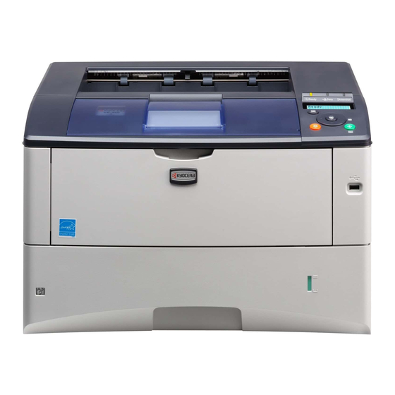
FS-6970DN
SERVICE
MANUAL
Published in March 2009
842J5110
2J5SM060
First Edition
Related Manuals for Kyocera FS-6970DN
Summary of Contents for Kyocera FS-6970DN
-
Page 1: Service Manual
FS-6970DN SERVICE MANUAL Published in March 2009 842J5110 2J5SM060 First Edition…
-
Page 2
CAUTION RISK OF EXPLOSION IF BATTERY IS REPLACED BY AN INCORRECT TYPE. DISPOSE OF USED BATTERIES ACCORDING TO THE INSTRUCTIONS. It may be illegal to dispose of this battery into the municipal waste stream. Check with your local solid waste officials for details in your area for proper disposal. ATTENTION IL Y A UN RISQUE D’EXPLOSION SI LA BATTERIE EST REMPLACEE PAR UN MODELE DE TYPE INCORRECT. -
Page 3
Revision history Revision Date Replaced pages Remarks… -
Page 4
This page is intentionally left blank. -
Page 5: Safety Precautions
Safety precautions This booklet provides safety warnings and precautions for our service personnel to ensure the safety of their customers, their machines as well as themselves during maintenance activities. Service personnel are advised to read this booklet carefully to familiarize themselves with the warnings and precautions described here before engaging in maintenance activities.
-
Page 6
Safety warnings and precautions Various symbols are used to protect our service personnel and customers from physical danger and to prevent damage to their property. These symbols are described below: DANGER: High risk of serious bodily injury or death may result from insufficient attention to or incorrect compliance with warning messages using this symbol. -
Page 7: Installation Precautions
1.Installation Precautions WARNING • Do not use a power supply with a voltage other than that specified. Avoid multiple connections to one outlet: they may cause fire or electric shock. When using an extension cable, always check that it is adequate for the rated current………………..•…
-
Page 8: Specifications 1
2.Precautions for Maintenance WARNING • Always remove the power plug from the wall outlet before starting machine disassembly….• Always follow the procedures for maintenance described in the service manual and other related brochures……………………….• Under no circumstances attempt to bypass or disable safety features including safety mechanisms and protective circuits.
-
Page 9
• Do not remove the ozone filter, if any, from the copier except for routine replacement….. • Do not pull on the AC power cord or connector wires on high-voltage components when removing them; always hold the plug itself…………………. •… -
Page 10
This page is intentionally left blank. -
Page 11
(1) Precautions ……………………….1-5-1 (2) Drum…………………………1-5-1 (3) Toner container ……………………..1-5-1 (4) How to tell a genuine Kyocera Mita toner container…………….1-5-2 1-5-2 Outer covers ……………………….1-5-3 (1) Detaching and refitting the top cover………………..1-5-3 (2) Detaching and refitting the right cover and left cover …………….1-5-4 1-5-3 Paper feed section ……………………..1-5-5… -
Page 12
1-5-6 Transfer/separation section ……………………1-5-14 (1) Detaching and refitting the transfer roller and separation charger brush unit ………1-5-14 1-5-7 Fuser section ……………………….1-5-16 (1) Detaching and refitting the fuser unit………………..1-5-16 (2) Detaching and refitting the fuser heater lamp M and S …………..1-5-17 (3) Detaching and refitting the heat roller …………………1-5-19 (4) Detaching and refitting the press roller………………..1-5-20 (5) Detaching and refitting the fuser thermistor M, fuser thermistor S and thermal cutout ….1-5-21… -
Page 13: Specifications
1-1 Specifications 1-1-1 Specifications Printing method……. Semiconductor laser and electrophotography Printing speeds ……. Simplex: A4: 35 ppm A5: 35 ppm A3: 17 ppm Duplex: A4: 24.5 ppm A5-R: 16 ppm A3: 10.5 ppm Paper sizes ……..Paper cassette: Ledger, Legal, Letter, A3, A4, B4, A5, JIS B5, A5, A6, Folio, Oficio II, Statement, Envelope C4, Envelope C5, ISO B5, Executive, 8 kai, 16 kai, Custom (148 ×…
-
Page 14
° ° Operation environment ….Temperature: 10 to 32.5 C/50 to 90.5 Relative humidity: 15 to 80% Altitude: 2,500 m/8,202 ft maximum Illumination: 1,500 lux maximum Dimensions (W × D × H) ….469 × 395 × 285 mm/18 × 15 ×… -
Page 15: Parts Names 1
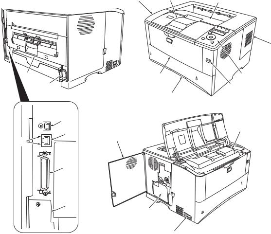
1-1-2 Parts names (1) Overall Figure 1-1-1 Top cover 11. Power switch Paper stopper 12. Waste toner box Top tray 13. USB interface connector Right side cover 14. Network indicators Operation panel 15. Network interface connector USB memory slot 16. Parallel interface connector Paper cassette 17.
-
Page 16
(2) Operation panel Figure 1-1-2 Indicators Message display Cursor keys GO Key Cancel Key OK Key MENU Key 1-1-4… -
Page 17
1-1-3 Machine cross section Paper path Paper path (optional) Figure 1-1-3 Machine cross section Rear unit MP (Multi-Purpose) tray 10. Fuser unit MP tray paper feed unit 11. Transfer/separation section Toner container 12. Duplex paper conveying section Developer unit 13. Paper cassette Main charger unit 14. -
Page 18
This page is intentionally left blank. 1-1-6… -
Page 19
1-2 Installation 1-2-1 Drum unit Note the following when handling or storing the drum (drum unit). Note the following when handling or storing the drum unit. When removing the drum unit, never expose the drum surface to strong direct light. Avoid abrupt changes in temperature and humidity. -
Page 20
1-2-4 Unpacking and installation (1) Unpacking Figure 1-2-2 Unpacking Printer Plastic bag Outer case 10. Installation guide etc. Bottom pad L 11. Plastic bag Bottom pad R 12. Toner container Machine cover 13. Power cord Top pad L 14. Waste toner box Top pad R 15. -
Page 21
1-2-5 Installing the expanding memory (optional) <Procedure> 1. Power off the printer and unplug the printer power cord. 2. Open the right side cover. 3. Remove the screw and open the inner cover. Right side cover Inner cover Screw Figure 1-2-3 4. -
Page 22
1-2-6 Installing the memory card (optional) <Procedure> 1. Turn off the printer and disconnect the power cord and printer cable. 2. Remove two screws and then open the option interface slot cover. 3. Install the memory card into the option inter- face slot. -
Page 23
1-2-7 Installing the hard disk (optional) <Procedure> 1. Turn off the printer and disconnect the power cord and printer cable. 2. Remove two screws and then open the option interface slot cover. 3. Install the hard disk into the option interface slot. -
Page 24
This page is intentionally left blank. 1-2-6… -
Page 25: Maintenance Mode
1-3 Maintenance Mode 1-3-1 Maintenance mode The printer is equipped with a maintenance function which can be used to maintain and service the machine. (1) Executing a maintenance item Message display Ready Press the MENU key. Report Print > Press the key several times until [Adjust/Maintenance >] is displayed.
-
Page 26: Service Status Page
(2) Contents of maintenance mode items Maintenance items Description Printing a status page for service purpose Description Prints a status page for service purpose. The status page includes various printing settings >>Print and service cumulative. Status Page Purpose To acquire the current printing environmental parameters and cumulative information. Procedure Enter the maintenance mode [>>Print Status Page].
-
Page 27
Maintenance items Description Service Status Page Printer Firmware Version 2J5_2000.000.000 2009.01.27 [XXXXXXXX] [XXXXXXXX] [XXXXXXXX] [XXXXXXXX] Engine Information NVRAM Version _1F31225_1F31225 MAC Address 00:00:00:00:00:00 100/100 0/0/0/0/0/0/0/ 0/0/0/0/0/0/0/ 0/0/0/0/0/0/0/0/ 0000000/0000000/0000000/0000000/0000000/0000000/0000000/0000000/ 0000000/0000000/0000000/0000000/ F00/U00/0/0/0/0/70/00/00/00/00/abcde/ 0000/0000/0000/0000/0000/0000/0000/0000/0000/0000/0000/0000/0000/0000/0000/ 0000/0000/0000/0000/0000/0000/0000/0000/0000/0000/ 0203040508090A0B0C0D0F101112131415161718191A1B1C1D1E1F202122235E 12345678/11223344/00001234abcd567800001234abcd5678/01234567890123456789012345678901/0008/00/07 XXXXXXXX FFFFFFFFFFFFFFFF/FFFFFFFFFFFFFFFF/FFFFFFFFFFFFFFFF/FFFFFFFFFFFFFFFF/ FFFFFFFFFFFFFFFF/FFFFFFFFFFFFFFFF/FFFFFFFFFFFFFFFF/FFFFFFFFFFFFFFFF/ FFFFFFFFFFFFFFFF/FFFFFFFFFFFFFFFF/FFFFFFFFFFFFFFFF/FFFFFFFFFFFFFFFF/ FFFFFFFFFFFFFFFF/FFFFFFFFFFFFFFFF/FFFFFFFFFFFFFFFF/FFFFFFFFFFFFFFFF/ FFFFFFFFFFFFFFFF/FFFFFFFFFFFFFFFF/FFFFFFFFFFFFFFFF/FFFFFFFFFFFFFFFF/ FFFFFFFFFFFFFFFF/FFFFFFFFFFFFFFFF/FFFFFFFFFFFFFFFF/FFFFFFFFFFFFFFFF/ FFFFFFFFFFFFFFFF/FFFFFFFFFFFFFFFF/FFFFFFFFFFFFFFFF/FFFFFFFFFFFFFFFF/ FFFFFFFFFFFFFFFF/FFFFFFFFFFFFFFFF/FFFFFFFFFFFFFFFF/FFFFFFFFFFFFFFFF/… -
Page 28
Maintenance items Description Detail of service status page Items Description Firmware version Engine software version Engine boot version Main ROM version Panel mask version Used memory Local time zone Toner coverage Number of pages printed converted in reference to A4 or Letter size. FRPO settings Machine serial No. -
Page 29
Maintenance items Description Items Description Machine/MP tray/Printer cassette/Paper feeder 1/Paper feeder 2/ Life counter (The first line) Paper feeder 3/Paper feeder 4/Duplex printing Life counter (The second — / — /Drum unit/Maintenance kit/ line) Operation panel lock status 0: Off 1: Partial lock 2: Full lock USB information… -
Page 30
Maintenance items Description Items Description Drum status Drum surface potential Drum sensitivity Quantity of light DRT parameter coefficient Optional paper feeder software Paper feeder 1/Paper feeder 2/Paper feeder 3/Paper feeder 4/ — version Optional font version Optional table version Optional message version Optional message version NOTE: Code conversion… -
Page 31
1. Enter the maintenance mode [>>Print Test Page]. 2. Press the OK key. [>>Print Test Page?] will be displayed. 3. Press the OK key. A sheet of test page will be printed. Completion FS-6970DN SN:SPL8307597 Counter:1135 Figure 1-3-3 Test page… -
Page 32
Maintenance items Description Counter reset for the maintenance kit Description >>Maintenance The «Install MK» message means that maintenance kit should be replaced at 300,000 pages of printing. The interval counter must be manually reset using this service item. Maintenance kit MK-450 Maintenance kit includes the following units: Drum unit Developer unit… -
Page 33
Maintenance items Description Automatic drum surface refreshing Description >>DRUM-CTRL The drum surface refreshing operation is normally performed when the power is turned on to the printer or during warm-up when the printer is recovering from the Sleep mode, but even then only at those times that the temperature/humidity sensor detects the drum surface to be in a state of dew condensation. -
Page 34
Printing an event log (EVENT LOG) Service items Description Printing an event log Printing an event log (EVENT LOG) (EVENT LOG) Description Prints a history list of occurrences of paper jam, self-diagnostics, toner replacements, etc. Purpose To allow machine malfunction analysis based on the frequency of paper misfeeds, self diag- nostic errors and replacements. -
Page 35: Event Log
Service items Description Detail of event log Event Log Printer Firmware Version 2J5_2000.000.000 2009.01.27 [XXXXXXXX] [XXXXXXXX] [XXXXXXXX] [XXXXXXXX] Paper Jam Log Service Call Log Count. Event Descriptions Count. Service Code 9999999 10. 01. 88. 01. 01 1111111 00. 0000 8888888 10.
-
Page 36
Service items Description Items Description Paper Count. Event Remembers 1 to 16 of occurrence. If The total page Log code (2 digit, hexadecimal, 6 the occurrence of the previous paper count at the time of categories) jam is less than 16, all of the paper the paper jam. -
Page 37
Service items Description Items Description Paper Reference 1: cont. Widthwise A4 size and lengthwise A5 are identical in length, however, the fuser tempera- ture differs. Detecting the fuser temperature depending on this temperature difference allows detection of paper misfeed due to a wrong paper size. Reference 2: The DU cover of the duplex paper conveying section is designed to operate as being held against the main unit as the paper cassette is installed. -
Page 38
Service items Description Items Description Paper Jam Log (b) Detail of paper source (Hexadecimal) cont. 00: MP tray 01: Paper cassette 1 (printer) 02: Paper cassette 2 (paper feeder 1) 03: Paper cassette 3 (paper feeder 2) 04: Paper cassette 4 (paper feeder 3) 05: Paper cassette 5 (paper feeder 4) 06: — 07: -… -
Page 39
Service items Description Items Description Maintenance Count. Item Remembers 1 to 8 of The total page count at the Code of maintenance replacing occurrence of replace- time of the replacement of item (1 byte, 2 categories) ment. If the occurrence of the toner container. -
Page 40
This page is intentionally left blank. 1-3-16… -
Page 41: Paper Misfeed Detection
1-4 Troubleshooting 1-4-1 Paper misfeed detection (1) Paper misfeed indication When a paper misfeed occurs, the printer immediately stops printing and displays the paper misfeed message on the operation panel. To remove paper misfed in the printer, pull out the paper cassette, pull out the rear unit, remove the devel- oper unit or open the duplex cover.
-
Page 42
1-4-2 Self-diagnostic function (1) Self-diagnostic function This printer is equipped with self-diagnostic function. When a problem is detected, the printer stops printing and display an error message on the operation panel. An error message consists of a message prompting a contact to service personnel, total print count, and a four-digit error code indicating the type of the error. -
Page 43
Remarks Code Contents Causes Check procedures/corrective measures 0420 Paper feeder communication error Improper installa- Follow installation instruction carefully again. Communication error between engine tion paper feeder. PWB and optional paper feeder. Defective harness Reinsert the connector. Also check for conti- between connect-L nuity within the connector harness. -
Page 44
Remarks Code Contents Causes Check procedures/corrective measures 4000 Polygon motor (laser scanner unit) Defective harness Reinsert the connector. Also check for conti- error between polygon nuity within the connector harness. If none, POLRDYN signal does not go low within motor and main remedy or replace the harness. -
Page 45
Remarks Code Contents Causes Check procedures/corrective measures 6000 Broken fuser heater lamp M wire Poor contact in the Reinsert the connector (See page P.1-5-21). ° fuser thermistor M The temperature does not reach 100 ° connector termi- F after the fuser heater lamp M has nals. -
Page 46
Remarks Code Contents Causes Check procedures/corrective measures 6230 Broken fuser thermistor M wire Poor contact in the Reinsert the connector (See page P.1-5-21). The detected temperature of fuser ther- fuser thermistor M ° ° connector termi- mistor S is 50 C/122 F or more and nals. -
Page 47
Remarks Code Contents Causes Check procedures/corrective measures 7410 Drum unit non- installing error The drum unit is Install the drum unit (See page P.1-5-12). The drum unit is not installed or not not installed. installed properly. Defective connec- Check the connection of connectors drum The drum PWB EEPROM does not com- tion drum PWB PWB (YC1) and connect-L PWB (YC3). -
Page 48: Image Formation Problems 1
1-4-3 Image formation problems (1)Completely blank (2)All-black printout. (3)Dropouts. (4)Black dots. (5)Black horizontal printout. streaks. P.1-4-9 P.1-4-10 P.1-4-11 P.1-4-11 P.1-4-12 (6)Black vertical (7)Unsharpness. (8)Gray background. (9)Dirt on the top (10)Undulated print- streaks. edge or back of the ing at the left edge paper.
-
Page 49
(1) Completely blank printout. Print example Causes Check procedures/corrective measures No trans- Poor contact of engine Check the installation position of the engine PWB. PWB’s transfer bias out- Refer to figure 1-4-3 below. charging. put terminal and printer’s contact (spring). Printer bottom Contact (spring) -
Page 50
(2) All-black printout. Print example Causes Check procedures/corrective measures No main Defective main charger Replace the main charger unit (See page P.1-5-13). charging. unit. Poor contact of engine Check the installation of the drum (main charger) unit (Refer to PWB’s main charger out- figure 1-4-5 below and P.1-5-12). -
Page 51
(3) Dropouts. Print example Causes Check procedures/corrective measures Defective developing roller (developer If the defects occur at regular intervals of 39 mm/1 » (See 9/16 unit). page P.2-4-2), the problem may be the damaged developing roller (in the developer unit). Replace developer unit. If a developer unit which is known to work normally is available for check, replace the current developer unit in the printer with the normal one. -
Page 52
(5) Black horizontal streaks. Print example Causes Check procedures/corrective measures Defective drum unit’s ground. Defective drum unit’s ground. The contact (spring) in the drum unit and its counter part, the drum grounding terminal in the printer, must be in a good contact. (See page P.1-4-9, refer to figure 1-4-3) Defective drum unit. -
Page 53
(8) Gray background. Print example Causes Check procedures/corrective measures Print density setting. The print density may be set too high. Try adjusting the print density. For details refer to the printer’s operation guide. Defective drum surface potential. If a drum unit which is known to work normally is available for check, replace the current drum unit in the printer with the nor- mal one. -
Page 54: Electric Problems
1-4-4 Electric problems Problem Causes Check procedures/corrective measures Defective waste toner sen- Replace the drum unit (See page P.1-5-12). Defective waste sor. toner box detecting. Defective connection Check the connection of connectors between drum PWB (YC1) between drum PWB (YC1) and connect-L PWB (YC3).
-
Page 55
Problem Causes Check procedures/corrective measures Broken power cord. Replace the power cord. Defective message The power cord is not Check the contact between the printer’s AC inlet and the AC displaying (LCD) [2]. plugged in properly. power outlet. No message appears on the message dis- No electricity at the AC Measure the AC input voltage. -
Page 56: Mechanical Problems
1-4-5 Mechanical problems Problem Causes/check procedures Corrective measures Check if the surfaces of the following rollers Clean with isopropyl alcohol. No primary paper feed. are dirty with paper powder: pickup roller, paper feed roller, and MP tray feed roller. Check if the pickup roller, paper feed roller Check visually and replace any deformed and MP tray feed roller are deformed.
-
Page 57
1-5 Assembly and Disassembly 1-5-1 Precautions for assembly and disassembly (1) Precautions Be sure to turn the power switch off and disconnect the power plug before starting disassembly. When handling PWBs, do not touch connectors with bare hands or damage the PWB. Do not touch any PWB containing ICs with bare hands or any object prone to static charge. -
Page 58
A black-colored band when seen through the left side window ( A shiny or gold-colored band when seen through the right side window ( The above will reveal that the toner container is a genuine Kyocera Mita branded toner container, otherwise, it is a coun- terfeit. -
Page 59: Outer Covers
1-5-2 Outer covers (1) Detaching and refitting the top cover Procedure 1. Open the top cover. Top cover 2. Remove two screws. 3. Remove the connector and then remove the top cover. Screw Screw Connector Figure 1-5-3 1-5-3…
-
Page 60
(2) Detaching and refitting the right cover and left cover Procedure 1. Remove the paper cassette. 2. Open the MP tray. 3. Open the rear unit. 4. Remove the top cover (See page P.1-5-3). 5. Unlatch three latches and then remove the right cover. -
Page 61
1-5-3 Paper feed section (1) Detaching and refitting the paper feed assembly (paper feed roller and pickup roller) Procedure 1. Remove the paper cassette. 2. Slide the paper feed roller pin. 3. While pressing the lever and then remove the paper feed roller assembly. 4. -
Page 62
(2) Detaching and refitting the retard roller Procedure 1. Remove the paper cassette. 2. Push the bottom plate down until it locks. Paper cassette 3. Unlatch two latches and then remove the retard guide. Bottom plate Latch Retard guide Latch Figure 1-5-7 4. -
Page 63
(3) Detaching and refitting the registration upper and lower roller Procedure 1. Remove the developer unit (See page P.1-5- Spring 11). 2. Remove the spring. 3. Pull the registration upper roller. Registration upper roller Figure 1-5-9 4. Remove the registration upper roller from the bush. -
Page 64
6. Remove the stopper. 7. Slide the bush. Stopper Bush Registration lower roller Figure 1-5-11 8. Remove the registration lower roller. 9. Remove the gear and three bushes from the Registration lower roller registration lower roller. Gear Bush Bush Bush 10. -
Page 65
(4) Detaching and refitting the MP tray paper feed roller Procedure 1. Remove the paper cassette. 2. Open the top cover. 3. Remove two holders from the main unit frame. MP tray Main unit frame Main unit frame Holder Holder MP tray MP tray (back side) -
Page 66
4. Remove two holders from the main unit frame. 5. Remove the MP tray. MP tray MP tray MP tray Holder Holder Main unit frame Main unit frame Figure 1-5-14 6. Pull the MP tray paper feed roller holder. 7. Slide the MP tray paper feed roller holder. MP tray paper 8. -
Page 67: Developer Section
1-5-4 Developer section (1) Detaching and refitting the developer unit Procedure 1. Open the top cover. Top cover 2. Open the MP tray. 3. Remove the developer unit. Developer unit 4. Check or replace the developer unit and refit all the removed parts. MP tray Figure 1-5-16 1-5-11…
-
Page 68
1-5-5 Drum section (1) Detaching and refitting the drum unit Procedure 1. Remove the developer unit (See page P.1-5- 11). 2. Open the left side cover and then remove the waste toner box. Left side cover 3. Unlock the drum unit lock and then remove the drum unit. -
Page 69
(2) Detaching and refitting the main charger unit Procedure 1. Remove the drum unit (See page P.1-5-12). Main charger unit 2. Unlock the lock lever and then remove the main charger unit. 3. Check or replace the main charger unit and Lock lever refit all the removed parts. -
Page 70
1-5-6 Transfer/separation section (1) Detaching and refitting the transfer roller and separation charger brush unit Procedure 1. Remove the developer unit (See page P.1-5- Paper chute guide 11). 2. Remove the drum unit (See page P.1-5-12). Hook 3. Slide the paper chute guide and unhook the Hook hooks. -
Page 71
6. Release six latches and then remove the separation charger brush unit. 7. Check or replace the transfer roller and sep- Separation charger aration charger brush unit and refit all the brush unit removed parts. CAUTION: Note the following, when refitting the separation charger brush unit. -
Page 72
1-5-7 Fuser section (1) Detaching and refitting the fuser unit Procedure Flat-blade 1. Open the rear unit. screwdriver 2. Insert a flat-blade screwdriver to push the fuser lock (gray colored) on the rear unit and the fuser unit is separated from the rear unit Fuser unit (rails). -
Page 73
(2) Detaching and refitting the fuser heater lamp M and S Procedure 1. Remove the fuser unit (See page P.1-5-16). Screw 2. Remove two screws and then open the fuser unit. NOTE: Screw When fixing the screw again, be careful not to tighten the screw too much because the fuser lower frame is made of resin. -
Page 74
4. Remove two screws from the fuser heater lamp M and S. Fuser heater lamp M 5. Remove the fuser heater lamp M and S. Screw 6. Check or replace the fuser heater lamp M Screw and S, and refit all the removed parts. Terminal Seat the fuser heater lamp M and S aligning Fuser heater… -
Page 75
(3) Detaching and refitting the heat roller Procedure 1. Remove the fuser heater lamp M and S (See page P.1-5-17). Heat L bush 2. Remove the heat roller from the fuser upper frame. 3. Remove the heat R bush, heat L bush, heat Heat roller gear Z46 and heat roller ground plate from Heat R bush… -
Page 76
(4) Detaching and refitting the press roller Procedure 1. Remove the fuser unit (See page P.1-5-16). 2. Open the fuser unit (See page P.1-5-17). 3. Remove the press roller from the fuser lower Bearing frame. 4. Remove two bearings. Press roller 5. -
Page 77
(5) Detaching and refitting the fuser thermistor M, fuser thermistor S and thermal cutout Procedure 1. Remove the fuser unit (See page P.1-5-16). 2. Turn the fuser unit bottom side up. Cord cover 3. Unlatch two latches and then remove the cord cover. -
Page 78
8. Remove the screw (nut) and then remove Spacer A Spacer B the fuser thermistor M. Insulating NOTE: sheet Screw Set spacer A so that its insulating sheet Fuser thermistor M faces the fuser thermistor. The number of spacer Bs differs depending on the fuser unit. -
Page 79
1-5-8 PWBs (1) Detaching and refitting the engine PWB Bottom plate 1 Procedure Screw 1. Remove the developer unit (See page P.1-5- 11). 2. Remove the drum unit (See page P.1-5-12). 3. Remove the top cover (See page P.1-5-3). 4. Remove the left cover (See page P.1-5-4). 5. -
Page 80
11. Detach the joint. 12. Remove eight screws and then remove the Joint DU base. DU base Screw Screw Screw Screw Screw Screw Screw Screw Figure 1-5-34 13. Remove four snaps. 14. Remove the tab. 15. Remove five connectors. Snap Snap Snap Snap… -
Page 81
16. Remove four screws. Screw Screw Screw Screw Figure 1-5-36 17. Detach the engine PWB assembly. 18. Remove four connectors. 19. Remove the engine PWB assembly. Connectors Connectors Engine PWB assembly Figure 1-5-37 1-5-25… -
Page 82
20. Remove the connector. 21. Remove two screws-A and then remove the EEPROM HV plate. 22. Remove two screws-B and then remove the engine R ground plate, engine L ground plate and shield plate. 23. Check or replace the engine PWB and refit all the removed parts. -
Page 83
(2) Detaching and refitting the main PWB Procedure 1. Remove the top cover (See page P.1-5-3). 2. Remove the right cover (See page P.1-5-4). Connectors 3. Remove six connectors from the main PWB. Connect-R PWB Main PWB 4. Remove thirteen connectors from the con- nect-R WPB. -
Page 84
7. Open the rear unit. 8. Remove six screws and then remove the controller box (main PWB). Screws Screw Rear unit Screw Controller box Screw Screw Figure 1-5-40 9. Remove five screws and then remove the main PWB from the controller box. Screw 10. -
Page 85
(3) Detaching and refitting the power source unit Procedure 1. Remove the top cover (See page P.1-5-3). 2. Remove the left cover (See page P.1-5-4). 3. Remove the drum unit (See page P.1-5-12). 4. Remove the connector (YC11) from the con- nect-L PWB. -
Page 86
7. Remove seven screws-A and then remove Grounding the drum grounding plate and two grounding terminal terminals. 8. Remove the screw-B and then remove the grounding terminal. 9. Remove the AC inlet. Screw-B AC inlet Screw-A (M3) Screw-A Screw-A (M3) Drum grounding plate… -
Page 87
13. Remove the connector. 14. Remove seven screws and then remove the power source PWB. Screw Screw 15. Check or replace the power source unit and refit all the removed parts. Screw Power source PWB Connector Heat sink plate Screws Power source plate Screws Figure 1-5-45… -
Page 88
1-5-9 Others (1) Detaching and refitting the paper feed drive unit Procedure Clamp 1. Remove the paper cassette. 2. Remove the developer unit (See page P.1-5- Right fan motor 11). Connect-R PWB 3. Remove the top cover (See page P.1-5-3). 4. -
Page 89
9. Remove three screws and then remove the paper feed drive unit. 10. Check or replace the paper feed drive unit and refit all the removed parts. 11. To refit the paper feed drive unit, make sure mesh of gears. Screw Screw Gear… -
Page 90
(2) Detaching and refitting the main drive unit Procedure 1. Remove the top cover (See page P.1-5-3). 2. Remove the right cover (See page P.1-5-4). 3. Remove the controller box (See page P.1-5- 27). 4. Remove two connectors. 5. Remove five screws and then remove the Screw main drive unit. -
Page 91
(3) Detaching and refitting the laser scanner unit Procedure 1. Remove the top cover (See page P.1-5-3). Main PWB 2. Remove the right cover (See page P.1-5-4). 3. Remove two connectors from the main PWB. Main PWB YC14 YC12 Connectors Figure 1-5-49 4. -
Page 92
(4) Direction of installing the principal fan motors When detaching or refitting the left fan motor or right fan motor, be careful of the airflow direction (intake or exhaust). Intake Left fan motor (Rating label: Inside) Intake Right fan motor (Rating label: Inside) Figure 1-5-51 1-5-36… -
Page 93: Downloading Firmware
1-6 Firmware 1-6-1 Downloading firmware Firmware files are named after the following codes: Firmware file name example Engine firmware D L _ E N G N . 2 J 5 master download file S 2 J 5 _ 1 0 0 0 0 0 0 0 2 4 . x Extention Software ID Product code…
-
Page 94
(1) Downloading the firmware from the USB memory To download data written in a USB memory to the printer, proceed as explained in this section. CAUTION Downloading firmware takes several minutes. Do not turn power off during downloading. If downloading is interrupted by an accidental power failure, etc., the main PWB may have to be replaced. -
Page 95
(2) Downloading the firmware from the memory card To download data written in a memory card (CompactFlash) to the printer, proceed as explained in this section. CAUTION Downloading firmware takes several minutes. Do not turn power off during downloading. If downloading is interrupted by an accidental power failure, etc., the main PWB may have to be replaced. -
Page 96
11. Confirm that the printer’s power switch is set to off. 12. Insert the memory card into the printer’s memory card slot. Memory card slot Memory card Figure 1-6-7 13. Turn printer power on. Power switch: On 14. When message display (1) is displayed to detect firmware in the memory card. -
Page 97: Paper Feed Section
2-1 Mechanical Construction 2-1-1 Paper feed section Paper feed section consists of the paper feed unit that feeds paper from the paper cassette and the MP tray paper feed unit that feeds paper from the MP tray, and the paper feed conveying section that conveys the fed paper to the transfer/ separation section.
-
Page 98
(2) MP tray paper feed section The MP tray can contain about 100 pages. Feeding is performed by the rotation of the MP tray feed roller from the MP tray. Function of the MP tray friction pad prevents papers from multiple feeding. Figure 2-1-3 MP tray paper feed section MP tray paper feed roller Bottom plate… -
Page 99
(3) Paper feed conveying section The conveying section consists of the parts shown in the following illustration and conveys papers from the paper cassette or the MP tray to the transfer/separation section when papers are fed. Paper by feeding or refeeding is conveyed by the middle feed roller to the position where the registration sensor is turned on, and then sent to the transfer/separation sec- tion by the upper registration roller and lower registration roller. -
Page 100
2-1-2 Drum section (1) Drum section The drum unit includes a photoconductive drum, eraser lamp, cleaning blade and, a main charger unit. The drum unit is removable with the main charger unit. Figure 2-1-7 Drum section Drum Main charger case Charger roller cleaning roller Main charger roller Main high voltage output (DC + AC) -
Page 101: Expose Section
2-1-3 Expose section (1) Laser scanner unit The charged surface of the drum is then scanned by the laser beam from the laser scanner unit. The laser beam is dis- persed as the polygon motor revolves to reflect the laser beam over the drum. Various lenses and mirror are housed in the laser scanner unit, adjust the diameter of the laser beam, and focalize it at the drum surface.
-
Page 102
Laser scanner unit POLCLK YC11-5 Polygon POLRDYN YC12-1 motor POLONN YC12-2 PDMASKN YC12-4 Laser Pin-photo beam sensor YC16-2 PD PWB Engine PWB Main PWB Laser diode Drum APC PWB OUTPEN YC12-3 PCONT YC11-12 SAMPLEN1 YC11-10 VDATAP1 YC11-8 VDATAN1 YC11-7 Figure 2-1-10Laser scanner unit block diagram 2-1-6… -
Page 103: Developing Section
2-1-4 Developing section (1) Developer unit The developing section consists of the developer unit and the toner container. The developer unit consists of the develop- ing roller where a magnetic brush is formed, the doctor blade and the agitator A and B that agitate the toner. Also, the toner sensor checks whether or not toner remains in the developer unit.
-
Page 104
2-1-5 Transfer/separation section (1) Transfer/separation section The image developed by toner on the drum is transferred onto the paper because of the electrical attraction between the toner itself and the transfer roller. The transfer roller is negatively biased so that the positively charged toner is attracted onto the paper while it is pinched by the drum and the transfer roller. -
Page 105: Cleaning Section
2-1-6 Cleaning section After the transferring process, the drum needs to be physically cleaned of toner which is residual after the development process. The cleaning blade is constantly pressed against the drum and scrapes the residual toner off to the cleaning roller.
-
Page 106
2-1-7 Fuser section (1) Fuser unit The fuse section consists of the following parts and fixes the toner that is transferred to the paper at the transfer/separa- tion section. The paper sent from the transfer/separation section is interleaved between the heat roller and the press roller. The heat roller is heated by the fuser heater lamp installed inside, and the toner is fused by heat and pressure and fixed onto the paper because the press roller is pressed by the fuser press spring. -
Page 107
Fuser unit Power source LIVE Thermal cutout YC102-3 COMMON1 YC102-1 COMMON2 Fuser YC102-5 thermistor S Fuser thermistor THERM2 Fuser Fuser YC506-15 heater THERM1 heater YC506-6 lamp M lamp S Heat EXITPAP roller YC506-4 Paper exit sensor Engine PWB Figure 2-1-18Fuser section block diagram 2-1-11… -
Page 108
2-1-8 Paper exit section/rear unit (1) Paper exit section/rear unit The paper exit section transports the paper which passed the fuser unit towards the top tray. The paper which passed through the fuser unit turns on the paper exit sensor which is driven by the fuser actuator in the fuser unit, and is led by the guide comprised of the rear cover and the frame, finally reaching the face down upper roller. -
Page 109
Face down tray paper full sensor Connect-L HPAP FDPFULN YC503-6 OUTA1 YC9-11 OUTA3 YC9-10 OUTB1 YC9-9 OUTB3 YC9-8 Connect-R Switch back motor Engine PWB Paper exit section Exit fan EXITFAN YC502-9 motor FDDRN YC506-8 FUDRN YC506-10 Face up/down solenoid Rear unit Duplex YC6-4 sensor… -
Page 110: Duplex Conveying Section
2-1-9 Duplex conveying section (1) Duplex conveying section Figure 2-1-21Duplex conveying section DU roller Duplex jam sensor DU feed pulley (actuator) DU base DU roller DU lower guide DU feed pulley DU roller (10) Feed upper guide DU feed pulley Connect-R Engine PWB Duplex jam…
-
Page 111: Electrical Parts Layout
2-2 Electrical Parts Layout 2-2-1 Electrical parts layout (1) Electrical parts layout Drum unit Fuser unit Developer unit Figure 2-2-1 Electrical parts layout Main PWB ………… Controls the software such as the print data processing and provides theinterface with computers. Engine PWB……….
-
Page 112
Connect-R PWB……….. Interconnects the engine PWB and the electrical parts. Connect-L PWB ……….. Interconnects the engine PWB and the electrical parts. Drum PWB ……….. Relays wirings from electrical components on the drum unit. Drum indi- vidual information in EEPROM storage. Developer PWB ……….. -
Page 113: Power Source Unit
2-3 Operation of the PWBs 2-3-1 Power source unit Power source unit MP tray paper feed sensor HANDSN ZCROSS Zero cross signal circuit SWSLEEPN Power switch Switching AC input regulator +5V1 circuit +24V1 Fuser Interlock heater switch lamp M HEATONN1 TRA51 Fuser heater lamp M control…
-
Page 114
YC102 Figure 2-3-2Power source unit silk-screen diagram Connector Pin No. Signal Voltage Description YC101 LIVE 220 — 240 V AC AC power input Connected NEUTRAL 220 — 240 V AC AC power input to the AC inlet YC102 COMMON1 220 — 240 V AC Fuser heater lamp M Connected N.C. -
Page 115: Paper Feeder
2-3-2 Engine PWB Right fan Fuser unit MP tray paper Duplex Developer Registration Middle feed Paper feed motor switch feed solenoid clutch solenoid clutch clutch clutch Connect-R PWB Operation Polygon panel PWB APC PWB PD PWB motor Exit fan Switchback motor motor Main motor…
-
Page 116
YC11 Figure 2-3-4Engine PWB silk-screen diagram 2-3-4… -
Page 117
Connector Signal Voltage Description OPSDO 0/5 V DC (pulse) Paper feeder serial communication data output signal Connected +24V2 24 V DC 24 V DC power source (via interlock switch) to the con- +24V2 24 V DC 24 V DC power source (via interlock switch) nect-L PWB Ground (YC7) -
Page 118
Connector Signal Voltage Description YC506 +5V1 5 V DC 5 V DC power source Connected THERM3 Analog Fuser unit detection voltage to the fuser +5V2 5 V DC 5 V DC power source unit EXITPAP 0/5 V DC Paper exit sensor: On/Off Ground THERM1 Analog… -
Page 119
Connector Signal Voltage Description YC15 +5V1 5 V DC 5 V DC power source Connected FFANDRN 0/2.5/5 V DC Feed fan motor: Full speed/Half speed/Off to the feed fan motor 2-3-7… -
Page 120
This page is intentionally left blank. 2-3-8… -
Page 121
2-4 Appendixes (1) Wiring diagram 2-4-1… -
Page 122
(2) Repetitive defects gauge First occurrence of defect 36 mm ( 1 » [Upper registration roller] 7/16 38.5 mm ( 1 » [Main charger roller] 39 mm ( 1 » [Developing roller] 9/16 52 mm ( 2 » [Lower registration roller] 1/16 55 mm ( 2 «… -
Page 123
(3) Maintenance parts list Maintenance part name Alternative Fig. Part No. Ref. No. part No. Name used in service Name used in parts list Maintenance kit MK-450 MK-450/MAINTENANCE KIT (OPTION) 1702J58EU0 072J58EU Separation charger DC BRUSH ASSY Transfer roller ROLLER TRANSFER ASSY SP Paper feed assembly FEED HOLDER ASSY Retard roller… -
Page 124
This page is intentionally left blank. 2-4-4…
-
Доставка заказа -
Условия предоставления услуг -
Мобильная версия -
Скачать-
Для прошивки принтера -
Драйвер для Epson -
Драйвер для Canon -
Драйвер для Samsung -
Драйвер для Xerox -
Драйвер для Hp -
Драйвер для Kyocera -
Драйвер для Lexmark -
Сервисный мануал-
Service Manual Epson -
Service manual Hp -
Service manual Canon -
Service manual Xerox -
Service manual Kyocera -
Service manual Tektronix -
Service manual Star -
Service manual Konica Minolta -
Service manual apple -
Service manual lexmark -
Service manual Intermec -
Service manual Genicom -
Service manual Brother -
Service manual Sharp -
Service manual Ricoh -
Service manual Oki -
Service manual Panasonic -
Service manual other
-
-
Сервисные программы -
Сервисные программы Epson -
Поиск по материалам статьи и скачать
-
-
Статьи-
О прошивке принтера -
Epson -
Canon -
HP -
Samsung -
Xerox -
Brother -
О СНПЧ и ПЗК разное -
О картридже -
Переделка принтера Epson -
Kyocera -
Ремонт майнеров, асиков
-
-
Информация-
Поиск товаров на сайте Vce-o-Printere.ru -
Регистрация и заказ товаров и посылок -
Гарантии и условия возврата -
Магазин в вашем городе -
Где мой заказ-
Состоянии посылки
-
-
Доставка -
Реквизиты оплаты -
Новости -
Контактная информация -
Сервисные центры -
О компании -
TOP 100 товаров -
Услуги в Москве -
Услуги в Питере -
Услуги в Волгограде-
Ремонт электроники в Волгограде
-
-
-
Где мой заказ -
Главная -
Ремонт электроники
-
Принтеры и МФУ -
-
Epson с СНПЧ и ПЗК -
Прошитый Samsung -
Принтер и МФУ HP -
Oki принтеры и мфу -
Ручной принтер -
Прошитый МФУ, принтер Pantum
-
-
СНПЧ -
-
СНПЧ Epson -
СНПЧ Canon -
СНПЧ Hp -
СНПЧ Brother -
СНПЧ Конструктор ( комплектующие )
-
-
Принтеры в разборе -
-
Epson струйные и лазерные принтеры и мфу -
HP струйные и лазерные принтеры и мфу -
Canon струйные и лазерные принтеры и мфу -
Samsung лазерные принтеры и мфу -
Brother струйные и лазерные принтеры и мфу -
OKI струйные и лазерные принтеры и МФУ -
Panasonic лазерные принтеры и мфу -
Xerox лазерные принтеры и МФУ -
Sharp лазерные принтеры и МФУ -
Ricoh лазерные принтеры и МФУ -
Kyocera лазерные принтеры и МФУ
-
-
ПЗК -
-
ПЗК Epson -
ПЗК HP -
ПЗК Canon -
ПЗК Brother
-
-
Чернила -
-
Чернила Epson -
Чернила Canon -
Чернила HP -
Чернила Brother -
Чернила Epson, Canon, HP в канистре
-
-
Фотобумага -
-
Фотобумага глянцевая -
Фотобумага матовая -
Фотобумага фактурная. Дизайнерская -
Рулонная фотобумага -
Фотобумага мелованная (2-х сторонний глянец для струйной печати) -
Оригинальная фотобумага HP, Canon, Epson
-
-
Термобумага для терминалов и банкоматов -
Тонер -
-
Тонер HP -
Тонер Samsung -
Тонер Canon -
Тонер Epson -
Тонер Xerox -
Тонер Brother -
Тонер Panasonic -
Тонер Kyocera -
Тонер OKI -
Тонер Ricoh -
Тонер Toshiba -
Тонер Konica -
Тонер Sharp -
Тонер Handan -
Тонер Lexmark
-
-
Лазерные картриджи -
-
Картридж Epson -
Картридж Canon -
Картридж HP -
Картридж Samsung -
Картридж Xerox -
Картридж Brother -
Картридж Panasonic -
Картридж Kyocera -
Картридж OKI -
Картридж Toshiba, Sharp, Lexmark, Ricoh
-
-
ЗИП для картриджа -
-
ЗИП картриджа Canon -
ЗИП картриджа HP -
ЗИП картриджа Samsung -
ЗИП картриджа Xerox -
ЗИП картриджа Brother -
ЗИП картриджа Panasonic -
ЗИП картриджа Lexmark -
ЗИП картриджа Ricoh, Kyocera, Sharp -
Пакеты для картриджей
-
-
Комплектующие (ЗИП) для принтера -
-
ЗИП Epson -
-
Print Head ( Печатающая головка ) -
Pump Assy ( Узел подачи чернил в сборе ) -
Board Assy ( Электронная плата ) -
DAMPER ( Демпер ) -
Cable Assy ( Шлейф в сборе ) -
Belt, Scale ( ремень каретки, лента позиционирования ) -
Motor Assy ( двигатель ) -
Paper feed unit ( узел подачи бумаги ) -
Gear ( Шестерня ) -
Scaner unit ( блок сканера ) -
Power Assy ( блок питания ) -
Разное Epson
-
-
ЗИП Canon -
-
Печатающая головка Canon -
Электронная плата Canon -
Узел термозакрепления Canon -
Узел подачи бумаги Canon -
Ремни, ленты позиционирования, диски энкодера Canon -
Шлейфы Canon -
Узел подачи чернил Canon -
Шестеренки Canon -
Блоки питания Canon -
Электродвигатели и соленоиды Canon -
Датчики Canon -
Разное Canon
-
-
ЗИП HP -
-
Печатающая головка HP -
Электронная плата HP -
Узел термозакрепления HP -
Узел подачи бумаги HP -
Ремни, ленты позиционирования, диски энкодера HP -
Шлейфы HP -
Узел подачи чернил HP -
Модули памяти HP -
Шестеренки HP -
Подшипники (бушинги) HP -
Блоки питания HP -
Электродвигатели и соленоиды HP -
Узел сканирования HP -
Датчики HP -
Разное HP
-
-
ЗИП Samsung -
-
Электронная плата Samsung -
Узел термозакрепления Samsung -
Узел подачи бумаги Samsung -
Шлейфы Samsung -
Шестеренки Samsung -
Подшипники (бушинги) Samsung -
Блоки питания Samsung -
Электродвигатели и соленоиды Samsung -
Узел сканирования Samsung -
Блок лазера Samsung -
Датчики Samsung -
Разное Samsung. Товары, не вошедшие в предыдущие категории
-
-
ЗИП Xerox -
-
Печатающая головка Xerox -
Электронная плата Xerox -
Узел термозакрепления Xerox -
Узел подачи бумаги Xerox -
Ремни, ленты позиционирования, диски энкодера Xerox -
Шлейфы Xerox -
Узел подачи чернил Xerox -
Шестеренки Xerox -
Электродвигатели и соленоиды Xerox -
Блоки питания Xerox -
Узел сканирования Xerox -
Датчики Xerox -
Блок лазера Xerox -
Разное Xerox
-
-
ЗИП Brother -
-
Печатающая головка Brother -
Электронная плата Brother -
Узел термозакрепления Brother -
Узел подачи бумаги Brother -
Ремни, ленты позиционирования, диски энкодера Brother -
Шлейфы Brother -
Узел подачи чернил Brother -
Шестеренки Brother -
Блоки питания Brother -
Электродвигатели и соленоиды Brother -
Датчики Brother -
Узел сканирования Brother -
Блок лазера Brother -
Разное Brother
-
-
ЗИП Kyocera -
-
Электронная плата Kyocera -
Узел термозакрепления Kyocera -
Узел подачи бумаги Kyocera -
Шлейфы Kyocera -
Шестеренки Kyocera -
Подшипники (бушинги) Kyocera -
Блоки питания Kyocera -
Электродвигатели и соленоиды Kyocera -
Узел сканирования Kyocera -
Блок лазера Kyocera -
Датчики Kyocera -
Разное Kyocera. Товары, не вошедшие в предыдущие категории
-
-
ЗИП Panasonic, OKI, Ricoh, Pantum -
-
Печатающая головка Panasonic, Oki, Ricoh, Pantum -
Электронная плата Panasonic, Oki, Ricoh, Pantum -
Узел термозакрепления Panasonic, Oki, Ricoh, Pantum -
Узел подачи бумаги Panasonic, Oki, Ricoh, Pantum -
Ремни, ленты позиционирования, диски энкодера Panasonic, Oki, Ricoh, Pantum -
Шлейфы Panasonic, Oki, Ricoh, Pantum -
Узел подачи чернил Panasonic, Oki, Ricoh, Pantum -
Шестеренки Panasonic, Oki, Ricoh, Pantum -
Блоки питания Panasonic, Oki, Ricoh, Pantum -
Электродвигатели и соленоиды Panasonic, Oki, Ricoh, Pantum -
Датчики Panasonic, Oki, Ricoh, Pantum -
Узел сканирования Panasonic, Oki, Ricoh, Pantum -
Блок лазера Panasonic, Oki, Ricoh, Pantum -
Разное Panasonic, Oki, Ricoh, Pantum
-
-
ЗИП Lexmark, Toshiba, Sharp -
-
Печатающая головка Lexmark, Toshiba, Sharp -
Электронная плата Lexmark, Toshiba, Sharp -
Узел термозакрепления Lexmark, Toshiba, Sharp -
Узел подачи бумаги Lexmark, Toshiba, Sharp -
Ремни, ленты позиционирования, диски энкодера Lexmark, Toshiba, Sharp -
Шлейфы Lexmark, Toshiba, Sharp -
Узел подачи чернил Lexmark, Toshiba, Sharp -
Шестеренки Lexmark, Toshiba, Sharp -
Блоки питания Lexmark, Toshiba, Sharp -
Электродвигатели и соленоиды Lexmark, Toshiba, Sharp -
Узел сканирования Lexmark, Toshiba, Sharp -
Блок лазера Lexmark, Toshiba, Sharp -
Датчики Lexmark, Toshiba, Sharp -
Разное Lexmark, Toshiba, Sharp
-
-
ЗИП Термопринтера -
Стекла для МФУ и сканера
-
-
Струйные картриджи -
-
Картриджи Epson -
Картриджи Canon -
Картриджи HP -
Картриджи Brother, Lexmark, Sharp
-
-
Чипы -
-
Чипы Epson -
Чипы Canon -
Чипы HP -
Чипы Samsung -
Чипы Xerox -
Чипы OKI -
Чипы Ricoh -
Чипы Pantum -
Чипы Kyocera -
Чипы Lexmark
-
-
Решение для принтера -
-
Прошивка Epson -
Генераторы, Прошивки Samsung -
Генераторы, Прошивки Xerox -
Прошитая оригиналом память -
Прошивка принтера Pantum -
Прошивки и Сервисные программы Canon
-
-
Химия для техники -
-
Промывочная жидкость -
Смазки и масла для техники -
Восстанавливающие, очищающие средства
-
-
Программаторы -
Радиодетали -
-
Транзисторы -
Микросхемы памяти FLASH -
Микросхемы памяти EEPROM -
Микроконтроллеры -
Конденсаторы -
Блок питания
-
-
Материалы для наружной рекламы -
Сублимация -
3D печать ABS PLA -
Планшетный принтер, текстильная печать -
Разработка сайтов и программного обеспечения -
Для ноутбука -
-
Зарядные устройства -
Аккумуляторы
-
-
Запчасти для телевизоров и мониторов -
-
Электронные платы для телевизоров -
Матрицы для телевизора -
Блоки питания для телевизоров -
Тюнеры для телевизора -
Светодиодная подсветка -
Шлейфы и кабели для телевизоров и мониторов -
Разное для телевизоров и мониторов
-
-
Запчасти для асиков (asic miner)
Вход

-
Написать письмо -
Карта сайта -
Поиск по сайту -
Контакты -
Доставка заказа -
Способы оплаты -
Свежий прайс -
Москва -
Политика в отношении обработки персональных данных
")
Счетчик Mail Рамблер
![]()
Адрес офиса: Москва Зеленый пр-кт 24 офис 4
Адрес склада: 400074 Волгоград ул. Баррикадная, 10 офис 002
Общий 8 8442 930011
Москва +7 499 781 18 69
Viber/Whatsapp +7 927 510 43 27 ICQ 631 756 623
Режим работы
Пнд птн с 9-00 до 18-00
Вы еще не просматривали товары
Вы еще ничего не добавили в блокнот
Вы еще ничего не добавили в сравнение
Вы еще ничего не добавили в корзину
![]()
FS-6970DN
SERVICE
MANUAL
Published in March 2010
842J5112
2J5SM062
Rev. 2
CAUTION
RISK OF EXPLOSION IF BATTERY IS REPLACED BY AN INCORRECT TYPE. DISPOSE OF USED BATTERIES ACCORDING TO THE INSTRUCTIONS.
It may be illegal to dispose of this battery into the municipal waste stream. Check with your local solid waste officials for details in your area for proper disposal.
ATTENTION
IL Y A UN RISQUE D’EXPLOSION SI LA BATTERIE EST REMPLACEE PAR UN MODELE DE TYPE INCORRECT. METTRE AU REBUT LES BATTERIES UTILISEES SELON LES INSTRUCTIONS DONNEES.
Il peut être illégal de jeter les batteries dans des eaux d’égout municipales. Vérifiez avec les fonctionnaires municipaux de votre région pour les détails concernant des déchets solides et une mise au rebut appropriée.
Revision history
|
Revision |
Date |
Replaced pages |
Remarks |
|
1 |
December 15, 2009 |
CONTENTS, 1-2-1, 1-3-2, 1-3-4, 1-4-4 to 1-4-7, 1-5-2, |
— |
|
2-2-1, 2-3-6, 2-3-7, 2-4-1 to 2-4-3 |
|||
|
2 |
March 26, 2010 |
1-3-2 to 1-3-6, 1-3-10, 1-3-12, 1-3-13 |
— |

This page is intentionally left blank.

Safety precautions
This booklet provides safety warnings and precautions for our service personnel to ensure the safety of their customers, their machines as well as themselves during maintenance activities. Service personnel are advised to read this booklet carefully to familiarize themselves with the warnings and precautions described here before engaging in maintenance activities.

Safety warnings and precautions
Various symbols are used to protect our service personnel and customers from physical danger and to prevent damage to their property. These symbols are described below:
 DANGER: High risk of serious bodily injury or death may result from insufficient attention to or incorrect compliance with warning messages using this symbol.
 WARNING: Serious bodily injury or death may result from insufficient attention to or incorrect compliance with warning messages using this symbol.
 CAUTION: Bodily injury or damage to property may result from insufficient attention to or incorrect compliance with warning messages using this symbol.
Symbols
The triangle ( ) symbol indicates a warning including danger and caution. The specific point of attention is shown inside the symbol.
General warning.
Warning of risk of electric shock.
Warning of high temperature.
 indicates a prohibited action. The specific prohibition is shown inside the symbol.
General prohibited action.
Disassembly prohibited.
 indicates that action is required. The specific action required is shown inside the symbol.
General action required.
Remove the power plug from the wall outlet.
Always ground the copier.

1.Installation Precautions
 WARNING
•Do not use a power supply with a voltage other than that specified. Avoid multiple connections to one outlet: they may cause fire or electric shock. When using an extension cable, always check that it is adequate for the rated current. …………………………………………………………………………………
•Connect the ground wire to a suitable grounding point. Not grounding the copier may cause fire or electric shock. Connecting the earth wire to an object not approved for the purpose may cause explosion or electric shock. Never connect the ground cable to any of the following: gas pipes, lightning rods, ground cables for telephone lines and water pipes or faucets not approved by the proper authorities. …………………………………………………………………………………………………………….
 CAUTION:
•Do not place the copier on an infirm or angled surface: the copier may tip over, causing injury. …….
•Do not install the copier in a humid or dusty place. This may cause fire or electric shock. …………….
•Do not install the copier near a radiator, heater, other heat source or near flammable material.
This may cause fire. ………………………………………………………………………………………………………….
•Allow sufficient space around the copier to allow the ventilation grills to keep the machine as cool as possible. Insufficient ventilation may cause heat buildup and poor copying performance. ………..
•Always handle the machine by the correct locations when moving it. ………………………………………..
•Always use anti-toppling and locking devices on copiers so equipped. Failure to do this may cause the copier to move unexpectedly or topple, leading to injury. …………………………………………………..
•Avoid inhaling toner or developer excessively. Protect the eyes. If toner or developer is accidentally ingested, drink a lot of water to dilute it in the stomach and obtain medical attention immediately. If it gets into the eyes, rinse immediately with copious amounts of water and obtain medical attention. ……………………………………………………………………………………………………………………..
•Advice customers that they must always follow the safety warnings and precautions in the copier’s instruction handbook. ………………………………………………………………………………………………………

2.Precautions for Maintenance
 WARNING
•Always remove the power plug from the wall outlet before starting machine disassembly. ……………
•Always follow the procedures for maintenance described in the service manual and other related brochures. ………………………………………………………………………………………………………………………
•Under no circumstances attempt to bypass or disable safety features including safety mechanisms and protective circuits. ………………………………………………………………………………………………………
•Always use parts having the correct specifications. ………………………………………………………………..
•Always use the thermostat or thermal fuse specified in the service manual or other related brochure when replacing them. Using a piece of wire, for example, could lead to fire or other serious accident. …………………………………………………………………………………………………………………………
•When the service manual or other serious brochure specifies a distance or gap for installation of a part, always use the correct scale and measure carefully. ……………………………………………………….
•Always check that the copier is correctly connected to an outlet with a ground connection. ………….
•Check that the power cable covering is free of damage. Check that the power plug is dust-free. If it is dirty, clean it to remove the risk of fire or electric shock. ……………………………………………………..
•Never attempt to disassemble the optical unit in machines using lasers. Leaking laser light may damage eyesight. ……………………………………………………………………………………………………………
•Handle the charger sections with care. They are charged to high potentials and may cause electric shock if handled improperly. ………………………………………………………………………………………………
CAUTION
•Wear safe clothing. If wearing loose clothing or accessories such as ties, make sure they are safely secured so they will not be caught in rotating sections. ………………………………………………….
•Use utmost caution when working on a powered machine. Keep away from chains and belts. ……..
•Handle the fixing section with care to avoid burns as it can be extremely hot. …………………………….
•Check that the fixing unit thermistor, heat and press rollers are clean. Dirt on them can cause abnormally high temperatures. …………………………………………………………………………………………..

•Do not remove the ozone filter, if any, from the copier except for routine replacement. ………………..
•Do not pull on the AC power cord or connector wires on high-voltage components when removing them; always hold the plug itself. ………………………………………………………………………………………..
•Do not route the power cable where it may be stood on or trapped. If necessary, protect it with a cable cover or other appropriate item. …………………………………………………………………………………
•Treat the ends of the wire carefully when installing a new charger wire to avoid electric leaks. ……..
•Remove toner completely from electronic components. ………………………………………………………….
•Run wire harnesses carefully so that wires will not be trapped or damaged. ………………………………
•After maintenance, always check that all the parts, screws, connectors and wires that were removed, have been refitted correctly. Special attention should be paid to any forgotten connector, trapped wire and missing screws. ………………………………………………………………………………………
•Check that all the caution labels that should be present on the machine according to the instruction handbook are clean and not peeling. Replace with new ones if necessary. ………………………………..
•Handle greases and solvents with care by following the instructions below: ……………………………….
·Use only a small amount of solvent at a time, being careful not to spill. Wipe spills off completely.
·Ventilate the room well while using grease or solvents.
·Allow applied solvents to evaporate completely before refitting the covers or turning the power switch on.
·Always wash hands afterwards.
•Never dispose of toner or toner bottles in fire. Toner may cause sparks when exposed directly to fire in a furnace, etc. ………………………………………………………………………………………………………..
•Should smoke be seen coming from the copier, remove the power plug from the wall outlet immediately. …………………………………………………………………………………………………………………………..
3.Miscellaneous
 WARNING
•Never attempt to heat the drum or expose it to any organic solvents such as alcohol, other than the specified refiner; it may generate toxic gas. ………………………………………………………………………….

This page is intentionally left blank.
|
2J5-1 |
|||
CONTENTS |
|||
|
1-1 Specifications |
|||
|
1-1-1 Specifications………………………………………………………………………………………………………………………… |
1-1-1 |
||
|
1-1-2 |
Parts names………………………………………………………………………………………………………………………….. |
1-1-3 |
|
|
(1) |
Overall …………………………………………………………………………………………………………………………….. |
1-1-3 |
|
|
(2) |
Operation panel………………………………………………………………………………………………………………… |
1-1-4 |
|
|
1-1-3 |
Machine cross section ……………………………………………………………………………………………………………. |
1-1-5 |
|
|
1-2 Installation |
|||
|
1-2-1 |
Drum unit ……………………………………………………………………………………………………………………………… |
1-2-1 |
|
|
1-2-2 Developer unit and toner container…………………………………………………………………………………………… |
1-2-1 |
||
|
1-2-3 |
Installation environment ………………………………………………………………………………………………………….. |
1-2-1 |
|
|
1-2-4 |
Unpacking and installation ………………………………………………………………………………………………………. |
1-2-2 |
|
|
(1) |
Unpacking ……………………………………………………………………………………………………………………….. |
1-2-2 |
|
|
1-2-5 Installing the expanding memory (option) ………………………………………………………………………………….. |
1-2-3 |
||
|
1-2-6 Installing the memory card (option)…………………………………………………………………………………………… |
1-2-4 |
||
|
1-2-7 Installing the hard disk (option) ………………………………………………………………………………………………… |
1-2-5 |
||
|
1-3 Maintenance Mode |
|||
|
1-3-1 |
Maintenance mode ………………………………………………………………………………………………………………… |
1-3-1 |
|
|
(1) |
Executing a maintenance item ……………………………………………………………………………………………. |
1-3-1 |
|
|
(2) |
Contents of maintenance mode items………………………………………………………………………………….. |
1-3-2 |
|
|
1-4 Troubleshooting |
|||
|
1-4-1 |
Paper misfeed detection …………………………………………………………………………………………………………. |
1-4-1 |
|
|
(1) |
Paper misfeed indication ……………………………………………………………………………………………………. |
1-4-1 |
|
|
(2) |
Paper misfeed detection…………………………………………………………………………………………………….. |
1-4-1 |
|
|
1-4-2 |
Self-diagnostic function…………………………………………………………………………………………………………… |
1-4-2 |
|
|
(1) |
Self-diagnostic function ……………………………………………………………………………………………………… |
1-4-2 |
|
|
(2) |
Self diagnostic codes ………………………………………………………………………………………………………… |
1-4-2 |
|
|
1-4-3 |
Image formation problems ………………………………………………………………………………………………………. |
1-4-8 |
|
|
(1) |
Completely blank printout…………………………………………………………………………………………………… |
1-4-9 |
|
|
(2) |
All-black printout……………………………………………………………………………………………………………… |
1-4-10 |
|
|
(3) |
Dropouts………………………………………………………………………………………………………………………… |
1-4-11 |
|
|
(4) |
Black dots………………………………………………………………………………………………………………………. |
1-4-11 |
|
|
(5) |
Black horizontal streaks. ………………………………………………………………………………………………….. |
1-4-12 |
|
|
(6) |
Black vertical streaks……………………………………………………………………………………………………….. |
1-4-12 |
|
|
(7) |
Unsharpness. …………………………………………………………………………………………………………………. |
1-4-12 |
|
|
(8) |
Gray background…………………………………………………………………………………………………………….. |
1-4-13 |
|
|
(9) |
Dirt on the top edge or back of the paper……………………………………………………………………………. |
1-4-13 |
|
|
(10) |
Undulated printing at the left edge (scanning start position). …………………………………………………. |
1-4-13 |
|
|
1-4-4 |
Electric problems …………………………………………………………………………………………………………………. |
1-4-14 |
|
|
1-4-5 |
Mechanical problems ……………………………………………………………………………………………………………. |
1-4-16 |
|
|
1-5 Assembly and Disassembly |
|||
|
1-5-1 Precautions for assembly and disassembly……………………………………………………………………………….. |
1-5-1 |
||
|
(1) |
Precautions ……………………………………………………………………………………………………………………… |
1-5-1 |
|
|
(2) |
Drum……………………………………………………………………………………………………………………………….. |
1-5-1 |
|
|
(3) |
Toner container ………………………………………………………………………………………………………………… |
1-5-1 |
|
|
(4) |
How to tell a genuine Kyocera Mita toner container……………………………………………………………….. |
1-5-2 |
|
|
1-5-2 |
Outer covers …………………………………………………………………………………………………………………………. |
1-5-3 |
|
|
(1) |
Detaching and refitting the top cover……………………………………………………………………………………. |
1-5-3 |
|
|
(2) |
Detaching and refitting the right cover and left cover ……………………………………………………………… |
1-5-4 |
|
|
1-5-3 |
Paper feed section …………………………………………………………………………………………………………………. |
1-5-5 |
|
|
(1) |
Detaching and refitting the paper feed assembly (paper feed roller and pickup roller) ………………… |
1-5-5 |
|
|
(2) |
Detaching and refitting the retard roller ………………………………………………………………………………… |
1-5-6 |
|
|
(3) |
Detaching and refitting the registration upper and lower roller…………………………………………………. |
1-5-7 |
|
|
(4) |
Detaching and refitting the MP tray paper feed roller……………………………………………………………… |
1-5-9 |
|
|
1-5-4 |
Developer section ………………………………………………………………………………………………………………… |
1-5-11 |
|
|
(1) |
Detaching and refitting the developer unit…………………………………………………………………………… |
1-5-11 |
2J5-1
|
1-5-5 |
Drum section……………………………………………………………………………………………………………………….. |
1-5-12 |
|
|
(1) |
Detaching and refitting the drum unit …………………………………………………………………………………. |
1-5-12 |
|
|
(2) |
Detaching and refitting the main charger unit………………………………………………………………………. |
1-5-13 |
|
|
1-5-6 |
Transfer/separation section …………………………………………………………………………………………………… |
1-5-14 |
|
|
(1) |
Detaching and refitting the transfer roller and separation charger brush unit …………………………… |
1-5-14 |
|
|
1-5-7 |
Fuser section ………………………………………………………………………………………………………………………. |
1-5-16 |
|
|
(1) |
Detaching and refitting the fuser unit………………………………………………………………………………….. |
1-5-16 |
|
|
(2) |
Detaching and refitting the fuser heater lamp M and S …………………………………………………………. |
1-5-17 |
|
|
(3) |
Detaching and refitting the heat roller ………………………………………………………………………………… |
1-5-19 |
|
|
(4) |
Detaching and refitting the press roller……………………………………………………………………………….. |
1-5-20 |
|
|
(5) |
Detaching and refitting the fuser thermistor M, fuser thermistor S and thermal cutout ………………. |
1-5-21 |
|
|
1-5-8 PWBs …………………………………………………………………………………………………………………………………. |
1-5-23 |
||
|
(1) |
Detaching and refitting the engine PWB …………………………………………………………………………….. |
1-5-23 |
|
|
(2) |
Detaching and refitting the main PWB ……………………………………………………………………………….. |
1-5-27 |
|
|
(3) |
Detaching and refitting the power source unit……………………………………………………………………… |
1-5-29 |
|
|
1-5-9 Others ………………………………………………………………………………………………………………………………… |
1-5-32 |
||
|
(1) |
Detaching and refitting the paper feed drive unit………………………………………………………………….. |
1-5-32 |
|
|
(2) |
Detaching and refitting the main drive unit………………………………………………………………………….. |
1-5-34 |
|
|
(3) |
Detaching and refitting the laser scanner unit……………………………………………………………………… |
1-5-35 |
|
|
(4) |
Direction of installing the principal fan motors……………………………………………………………………… |
1-5-36 |
1-6 Firmware
|
1-6-1 Downloading firmware ……………………………………………………………………………………………………………. |
1-6-1 |
|
|
(1) |
Downloading the firmware from the USB memory …………………………………………………………………. |
1-6-2 |
|
(2) |
Downloading the firmware from the memory card………………………………………………………………….. |
1-6-3 |
2-1 Mechanical Construction
|
2-1-1 |
Paper feed section …………………………………………………………………………………………………………………. |
2-1-1 |
|
|
(1) |
Paper cassette paper feeding …………………………………………………………………………………………….. |
2-1-1 |
|
|
(2) |
MP tray paper feed section ………………………………………………………………………………………………… |
2-1-2 |
|
|
(3) |
Paper feed conveying section …………………………………………………………………………………………….. |
2-1-3 |
|
|
2-1-2 |
Drum section…………………………………………………………………………………………………………………………. |
2-1-4 |
|
|
(1) |
Drum section ……………………………………………………………………………………………………………………. |
2-1-4 |
|
|
2-1-3 |
Expose section………………………………………………………………………………………………………………………. |
2-1-5 |
|
|
(1) |
Laser scanner unit…………………………………………………………………………………………………………….. |
2-1-5 |
|
|
2-1-4 |
Developing section…………………………………………………………………………………………………………………. |
2-1-7 |
|
|
(1) |
Developer unit ………………………………………………………………………………………………………………….. |
2-1-7 |
|
|
2-1-5 |
Transfer/separation section …………………………………………………………………………………………………….. |
2-1-8 |
|
|
(1) |
Transfer/separation section………………………………………………………………………………………………… |
2-1-8 |
|
|
2-1-6 |
Cleaning section ……………………………………………………………………………………………………………………. |
2-1-9 |
|
|
2-1-7 |
Fuser section ………………………………………………………………………………………………………………………. |
2-1-10 |
|
|
(1) |
Fuser unit ………………………………………………………………………………………………………………………. |
2-1-10 |
|
|
2-1-8 Paper exit section/rear unit ……………………………………………………………………………………………………. |
2-1-12 |
||
|
(1) |
Paper exit section/rear unit……………………………………………………………………………………………….. |
2-1-12 |
|
|
2-1-9 |
Duplex conveying section ……………………………………………………………………………………………………… |
2-1-14 |
|
|
(1) |
Duplex conveying section…………………………………………………………………………………………………. |
2-1-14 |
|
2-2 |
Electrical Parts Layout |
||
|
2-2-1 |
Electrical parts layout……………………………………………………………………………………………………………… |
2-2-1 |
|
|
(1) Electrical parts layout ………………………………………………………………………………………………………… |
2-2-1 |
||
|
2-3 |
Operation of the PWBs |
||
|
2-3-1 |
Power source unit ………………………………………………………………………………………………………………….. |
2-3-1 |
|
|
2-3-2 |
Engine PWB………………………………………………………………………………………………………………………….. |
2-3-3 |
2-4 Appendixes
|
Repetitive defects gauge ………………………………………………………………………………………………………… |
2-4-1 |
|
Wiring diagram………………………………………………………………………………………………………………………. |
2-4-3 |
2J5
1-1-1 Specifications
|
Printing method…………………………. |
Semiconductor laser and electrophotography |
|
Printing speeds …………………………. |
Simplex: |
|
A4: 35 ppm |
|
|
A5: 35 ppm |
|
|
A3: 17 ppm |
|
|
Duplex: |
|
|
A4: 24.5 ppm |
|
|
A5-R: 16 ppm |
|
|
A3: 10.5 ppm |
|
|
Paper sizes ………………………………. |
Paper cassette: |
|
Ledger, Legal, Letter, A3, A4, B4, A5, JIS B5, A5, A6, Folio, Oficio II, Statement, |
|
|
Envelope C4, Envelope C5, ISO B5, Executive, 8 kai, 16 kai, |
|
|
Custom (148 × 210 to 297 × 432 mm) |
|
|
MP tray: |
|
|
Ledger, Legal, Letter, A3, A4, B4, A5, JIS B5, A5, A6, Folio, Oficio II, Envelope, |
|
|
Monarch, Envelope #10, Envelope DL, Statement, Envelope C4, Envelope C5, |
|
|
ISO B5, Executive, Envelope #9, Envelope #6, Hagaki, Ofuku-Hagaki, 8 kai, 16 kai, |
|
|
Yokei 2, Yokei 4, Custom (70 × 148 to 297 × 450 mm) |
|
|
Paper types………………………………. |
Paper cassette: |
|
Plain, Preprinted, Bond, Recycled, Rough, Letterhead, Color (Colour), |
|
|
Prepunched, High Quality, and Custom (1 to |
|
|
MP tray: |
|
|
Plain, Transparency, Preprinted, Labels, Bond, Recycled, Rough, Vellum, |
|
|
Letterhead, Color (Colour), Prepunched, Envelope, Cardstock, Thick paper, |
|
|
High Quality, and Custom (1 to |
|
|
Resolution………………………………… |
Fine 1200, Fast 1200 mode, 600 dpi, 300 dpi |
|
Warm-up time (22 °C/71.6 °F, 60%RH) … |
Power on: 15 seconds or less |
|
Sleep: 15 seconds or less |
|
|
First print out (A4) ……………………… |
9 seconds or less when EcoFuser is Off and the printer is in Ready status. |
|
24 seconds or less when EcoFuser is On and the printer is in sleep mode. |
|
|
Paper feed source capacity ………… |
Paper cassette: 250 sheets (80 g/m2) |
|
MP tray: 100 sheets (80 g/m2) |
|
|
Output ray capacity……………………. |
Top tray: 250 sheets (80 g/m2) |
|
Face up tray (optional): PT-430: 250 sheets (80 g/m2) |
|
|
Photo conductor………………………… |
a-Si (diameter: 30mm/1 3/16«) |
|
Charging system……………………….. |
Contact charger roller method (positive charging) |
|
Developing system ……………………. |
Single component developer |
|
Transfer system ………………………… |
Transfer roller |
|
Separation system …………………….. |
Separation brush (DC bias) |
|
Fixing System …………………………… |
Heat fusing with a heat roller and a press roller |
|
Charge erasing system………………. |
Light emitted by LED |
|
Cleaning system ……………………….. |
Counter blade cleaning |
|
Operating systems…………………….. |
Windows 2000 Service Pack 2 or later, Windows Server 2003, Windows XP, |
|
Windows Vista, Mac OS X 10.x |
|
|
Controller …………………………………. |
PowerPC440/600 MHz |
|
Memory……………………………………. |
Standard: 128 MB |
|
Maximum: 1152 MB |
|
|
Interface…………………………………… |
Standard: |
|
Parallel: 1 (IEEE1284) |
|
|
Hi-Speed USB: 1 |
|
|
Network: 1(10BASE-T/100BASE-TX) |
|
|
Full-speed USB: 1 (USB flash memory slot) |
|
|
KUIO-LV(W) slot |

1-1-1
|
2J5 |
|
|
Operation environment ………………. |
Temperature: 10 to 32.5°C/50 to 90.5°F |
|
Relative humidity: 15 to 80% |
|
|
Altitude: 2,500 m/8,202 ft maximum |
|
|
Illumination: 1,500 lux maximum |
|
|
Dimensions (W × D × H) …………….. |
469 × 395 × 285 mm/18 7/16 × 15 9/16 × 11 1/4« |
|
Weight (without toner container) ….. |
19.5 kg/43 lbs |
|
Power source……………………………. |
220-240 V, 50 Hz/60 Hz, max. 3.9 A (European countries) Max. |
|
Allowable voltage fluctuation: ±10% Max. |
|
|
Allowable frequency fluctuation: ±2% |
|
|
Power consumption …………………… |
Maximum 976 W |
|
During printing: 516 W |
|
|
During standby: 9.6 W (EcoFuser: ON), 67 W (EcoFuser: OFF) |
|
|
Power off: 0 W |
1-1-2
2J5
1-1-2 Parts names
(1) Overall
4
19  8
8  5
5
|
13 |
|
|
10 |
|
|
15 |
9 |
|
14 |
|
|
16 |
17
12
|
11 |
|||
|
Figure 1-1-1 |
|||
|
1. |
Top cover |
11. |
Power switch |
|
2. |
Paper stopper |
12. |
Waste toner box |
|
3. |
Top tray |
13. |
USB interface connector |
|
4. |
Right side cover |
14. |
Network indicators |
|
5. |
Operation panel |
15. |
Network interface connector |
|
6. |
USB memory slot |
16. |
Parallel interface connector |
|
7. |
Paper cassette |
17. |
Option interface slot |
|
8. |
MP (Multi-Purpose) tray |
(Memory card/Hard disk) |
|
|
9. |
Left side cover |
18. |
AC inlet |
|
10. |
Toner container |
19. |
Rear unit |
1-1-3
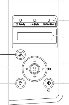
2J5
(2) Operation panel
|
1 |
|
|
2 |
|
|
7 |
|
|
6 |
3 |
|
5 |
4 |
Figure 1-1-2
1. Indicators
2. Message display
3. Cursor keys
4. GO Key
5. Cancel Key
6. OK Key
7. MENU Key
1-1-4
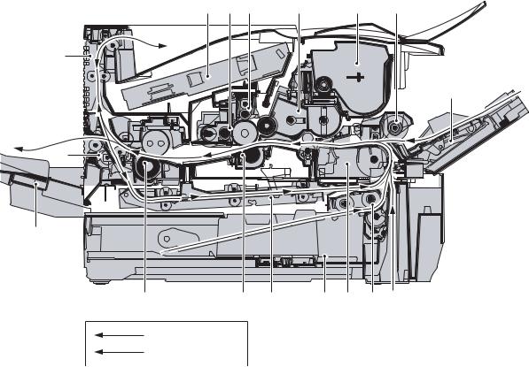
2J5
1-1-3 Machine cross section
Paper path
Paper path (optional)
|
Figure 1-1-3 Machine cross section |
|||
|
1. |
MP (Multi-Purpose) tray |
9. |
Rear unit |
|
2. |
MP tray paper feed unit |
10. |
Fuser unit |
|
3. |
Toner container |
11. |
Transfer/separation section |
|
4. |
Developer unit |
12. |
Duplex paper conveying section |
|
5. |
Main charger unit |
13. |
Paper cassette |
|
6. |
Drum unit |
14. |
Paper conveying section |
|
7. |
Laser scanner unit |
15. |
Paper cassette paper feed section |
|
8. |
Paper exit section |
16. |
Face-up tray (optional) |
1-1-5

2J5
This page is intentionally left blank.
1-1-6
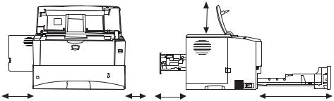
2J5-1
1-2-1 Drum unit
Note the following when handling or storing the drum (drum unit).
Note the following when handling or storing the drum unit.
1.When removing the drum unit, never expose the drum surface to strong direct light.
2.Avoid abrupt changes in temperature and humidity.
3.Avoid exposure to any substance which is harmful to or may affect the quality of the drum.
4.Do not touch the drum surface with any object. Should it be touched by hands or stained with oil, clean it.
1-2-2 Developer unit and toner container
Store the toner container in a cool, dark place.
Avoid direct light and high humidity.
1-2-3 Installation environment
1.Temperature: 10 to 32.5°C/50 to 90.5°F
2.Humidity: 15 — 80%RH
3.Power supply: 220 — 240 V AC, 3.9 A
4.Power source frequency: 50 Hz ±0.3%/60 Hz ±0.3%
5.Installation location
Avoid direct sunlight or bright lighting. Ensure that the photoconductor will not be exposed to direct sunlight or other strong light when removing paper jams.
Avoid locations subject to high temperature and high humidity or low temperature and low humidity; an abrupt change in the environmental temperature; and cool or hot, direct air.
Avoid places subject to dust and vibrations.
Choose a surface capable of supporting the weight of the machine.
Place the machine on a level surface (maximum allowance inclination: 1°).
Avoid air-borne substances that may adversely affect the machine or degrade the photoconductor, such as mercury, acidic of alkaline vapors, inorganic gasses, NOx, SOx gases and chlorine-based organic solvents.
Select a well-ventilated location.
6.Allow sufficient access for proper operation and maintenance of the machine.
Top: 300 mm
(11 13/16«)
|
Left: 300 mm |
Right: 100 mm |
Rear: 200 mm |
Front: 600 mm |
|
(11 13/16«) |
(3 15/16«) |
(7 7/8«) |
(23 5/8«) |
|
400 mm (15 3/4» ) |
|||
|
when the optional |
|||
|
face up tray (PT-430) |
|||
|
is attached. |
Figure 1-2-1
1-2-1
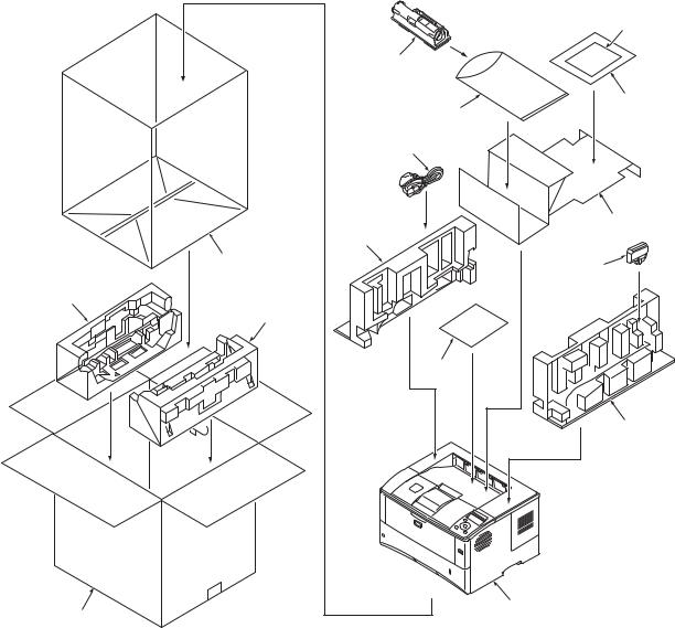
2J5
1-2-4 Unpacking and installation
(1) Unpacking
|
Figure 1-2-2 Unpacking |
|
1. |
Printer |
9. |
Plastic bag |
|
2. |
Outer case |
10. |
Installation guide etc. |
|
3. |
Bottom pad L |
11. |
Plastic bag |
|
4. |
Bottom pad R |
12. |
Toner container |
|
5. |
Machine cover |
13. |
Power cord |
|
6. |
Top pad L |
14. |
Waste toner box |
|
7. |
Top pad R |
15. |
Leaflet |
8.Accessory spacer
1-2-2
![]()
2J5
1-2-5 Installing the expanding memory (option)
<Procedure>
1. Power off the printer and unplug the printer power cord.
2.Open the right side cover.
3.Remove the screw and open the inner cover.
Right side cover
4.Aligning the cutouts of the memory module with the matching keys of the socket, carefully plug the memory module into the memory socket until it clicks in place.
5.Then, push down the memory module to secure.
6.Close and secure the inner cover by one screw.
7.Refit the right side cover.
Verifying the expanded memory
1.To verify that the memory module is working properly, test it by printing a status page.
|
Inner cover |
|
Screw |
|
Figure 1-2-3 |
Memory module 

Cutout
Memory socket
Figure 1-2-4
1-2-3
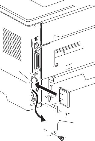
2J5
1-2-6 Installing the memory card (option)
<Procedure>
1.Turn off the printer and disconnect the power cord and printer cable.
2.Remove two screws and then open the option interface slot cover.
3.Install the memory card into the option interface slot.
4.Refit the option interface slot cover by two screws.
Memory card slot
 Memory card

 Screw
Screw
 Option interface slot cover
 Screw
Screw
Figure 1-2-5
1-2-4
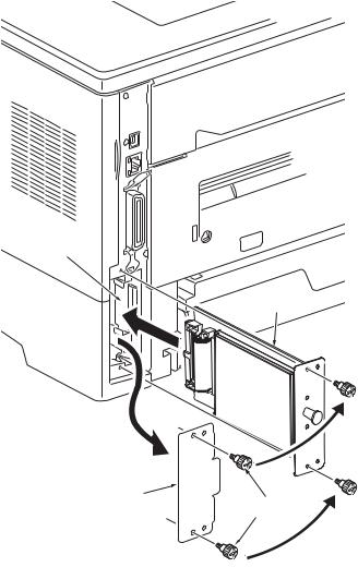
2J5
1-2-7 Installing the hard disk (option)
<Procedure>
1.Turn off the printer and disconnect the power cord and printer cable.
2.Remove two screws and then open the option interface slot cover.
3.Install the hard disk into the option interface slot.
4.Refit the option interface slot cover by two screws.
Hard disk
|
Option interface |
|
|
slot cover |
Screws |
Figure 1-2-6
1-2-5

2J5
This page is intentionally left blank.
1-2-6
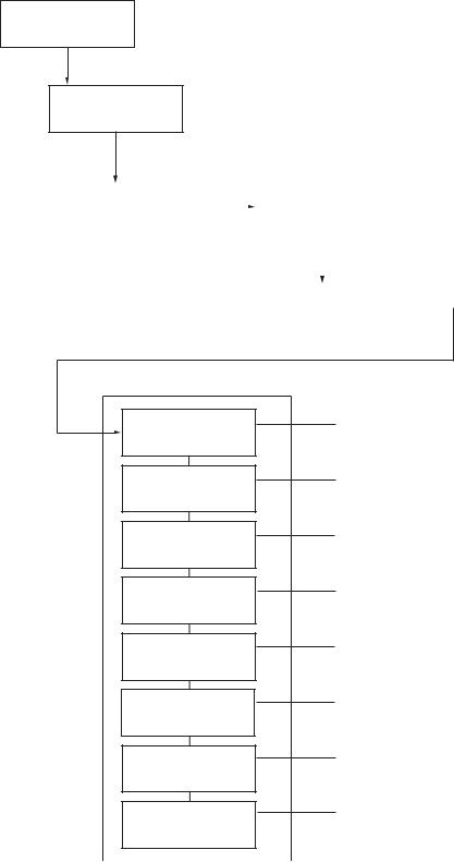
2J5
1-3-1 Maintenance mode
The printer is equipped with a maintenance function which can be used to maintain and service the machine.
(1) Executing a maintenance item
Message display
Ready
Press the MENU key.
Report Print >
Press the or key several times until [Adjust/Maintenance >] is displayed.
|
Adjust/ |
> |
>Restart |
||||||
|
Maintenance |
Printer |
|||||||
|
Press the key. |
Press the or key several times |
|||||||
|
until [>Service >] is displayed. |
||||||||
|
>Service |
> |
|||||||
Press the key.
Maintenance mode items
To scroll these items, press the or key repeatedly.
>>Print Status Page
>>Print Network Status Page
>>Print Test Page
>>Write Data
>>Maintenance
>>Developer
>>DRUM-CTRL
>>Drum
To print a status page for service purpose.
(See page 1-3-2)
To print a network status page.
(See page 1-3-6)
Prints a test page which contains halftone.
(See page 1-3-7)
To write data into a USB memory.
(See page 1-3-7)
To reset counter for the maintenance kit.
(See page 1-3-8)
To initialize the developing unit. (toner install mode)
(See page 1-3-8)
To perform a automatic drum refreshing.
(See page 1-3-9)
To perform a drum refreshing.
(See page 1-3-9)
1-3-1
2J5-2
(2) Contents of maintenance mode items
|
Maintenance items |
Description |
|||
|
Printing a status page for service purpose |
||||
|
Description |
||||
|
|
Prints a status page for service purpose. The status page includes various printing settings |
|||
|
Status Page |
and service cumulative. |
|||
|
Purpose |
||||
|
To acquire the current printing environmental parameters and cumulative information. |
||||
|
Procedure |
||||
|
1. |
Enter the maintenance mode [>>Print Status Page]. |
|||
|
2. |
Press the OK key. [Print Status Page?] will be displayed. |
|||
|
3. |
Press the OK key. Two pages will be printed. |
|||
|
Completion |
||||
Service Status Page
Printer
|
Firmware Version 2J5_2000.000.000 2009.01.27 |
[XXXXXXXX] [XXXXXXXX] [XXXXXXXX] [XXXXXXXX] |
|||
Controller Information
Memory Status
|
Standard Size |
500.0 KB |
|
Option Slot |
500.0 KB |
|
Total Size |
1000.0 KB |
Time
|
Local Time Zone |
+01:00 Amsterdam |
|
Time Server |
10. 183. 53. 13 |
Installed Options
|
Paper feeder 2 |
Installed |
||||
|
Paper feeder 3 |
Installed |
e-MPS error control |
Y6 |
0 |
|
|
Memory Card |
Installed |
||||
|
Hard Disk |
Installed |
Digital Dot Coverage
|
Average (%) |
/ Usage Page (A4/Letter Conversion) |
|
K: 1.00 |
/ 1111111.00 |
|
Last page (%) |
1.00 |
FRPO Status
|
Default Pattern Switch |
B8 |
0 |
|
Default Font Number |
C5*10000+C2*100+C3 |
00000 |
Figure 1-3-1Service status page (1)
1-3-2

2J5-2
|
Maintenance items |
Description |
Service Status Page
Printer
Firmware Version 2J5_2000.000.000 2009.01.27 [XXXXXXXX] [XXXXXXXX] [XXXXXXXX] [XXXXXXXX]
Engine Information
|
NVRAM Version |
_1F31225_1F31225 |
|
|
MAC Address |
00:00:00:00:00:00 |
1/2
100/100
0/0/0/0/0/0/0/
0/0/0/0/0/0/0/
0/0/0/0/0/0/0/0/
0000000/0000000/0000000/0000000/0000000/0000000/0000000/0000000/
0000000/0000000/
F00/U00/0/0/0/0/70/00/00/00/00/abcde/1/
0000/0000/0000/0000/0000/0000/0000/0000/0000/0000/0000/0000/0000/0000/0000/
0000/0000/0000/0000/0000/0000/0000/0000/0000/0000/
0203040508090A0B0C0D0F101112131415161718191A1B1C1D1E1F202122235E
12345678/11223344/00001234abcd567800001234abcd5678/01234567890123456789012345678901/0008/00/07 XXXXXXXX/t/
FFFFFFFFFFFFFFFF/FFFFFFFFFFFFFFFF/FFFFFFFFFFFFFFFF/FFFFFFFFFFFFFFFF/
FFFFFFFFFFFFFFFF/FFFFFFFFFFFFFFFF/FFFFFFFFFFFFFFFF/FFFFFFFFFFFFFFFF/
FFFFFFFFFFFFFFFF/FFFFFFFFFFFFFFFF/FFFFFFFFFFFFFFFF/FFFFFFFFFFFFFFFF/
FFFFFFFFFFFFFFFF/FFFFFFFFFFFFFFFF/FFFFFFFFFFFFFFFF/FFFFFFFFFFFFFFFF/
FFFFFFFFFFFFFFFF/FFFFFFFFFFFFFFFF/FFFFFFFFFFFFFFFF/FFFFFFFFFFFFFFFF/
FFFFFFFFFFFFFFFF/FFFFFFFFFFFFFFFF/FFFFFFFFFFFFFFFF/FFFFFFFFFFFFFFFF/
FFFFFFFFFFFFFFFF/FFFFFFFFFFFFFFFF/FFFFFFFFFFFFFFFF/FFFFFFFFFFFFFFFF/
FFFFFFFFFFFFFFFF/FFFFFFFFFFFFFFFF/FFFFFFFFFFFFFFFF/FFFFFFFFFFFFFFFF/
/00/ /00000000000000000000000000000000/00000000000000000000000000000000
/0000000000000000000000000000000000000000000000000000000000000000
/00000000/00000000/00000000/00000000/00000000/00000000/00000000/00000000/00000000/00000000/
/00000000/00000000/00000000/00000000/00000000/00000000/00000000/00000000/00000000/00000000/
/00000000/00000000/00000000/00000000/00000000/00000000/00000000/00000000/00000000/00000000/
/00000000/00000000/00000000/00000000/00000000/00000000/00000000/00000000/00000000/00000000/
/00000000/00000000/00000000/00000000/00000000/00000000/00000000/00000000/00000000/00000000/
/00000000/00000000/00000000/00000000/00000000/00000000/00000000/00000000/00000000/00000000/
/00000000/00000000/00000000/00000000/00000000/00000000/00000000/00000000/00000000/00000000/
/00000000/00000000/00000000/00000000/00000000/00000000/00000000/00000000/00000000/00000000/
/00000000/00000000/00000000/00000000/00000000/00000000/00000000/00000000/00000000/00000000/
/00000000/00000000/00000000/00000000/00000000/00000000/00000000/00000000/00000000/00000000/
/00000000/00000000/00000000/00000000/00000000/00000000/00000000/00000000/00000000/00000000/
/00000000/00000000/00000000/00000000/00000000/00000000/00000000/00000000/00000000/00000000/
/00000000/00000000/00000000/00000000/00000000/00000000/00000000/00000000/00000000/00000000/
/00000000/00000000/00000000/00000000/00000000/00000000/00000000/00000000/00000000/00000000/
/00000000/00000000/00000000/00000000/00000000/00000000/00000000/00000000/00000000/00000000/
/00000000/00000000/00000000/00000000/00000000/00000000/00000000/00000000/00000000/00000000/
/00000000/00000000/00000000/00000000/00000000/00000000/00000000/00000000/00000000/00000000/
/00000000/00000000/00000000/00000000/00000000/00000000/00000000/00000000/00000000/00000000/
/00000000/00000000/00000000/00000000/00000000/00000000/00000000/00000000/00000000/00000000/
/00000000/00000000/00000000/00000000/00000000/00000000/00000000/00000000/00000000/00000000/
/00000000/00000000/00000000/00000000/00000000/00000000/00000000/00000000/00000000/00000000/
/00000000/00000000/00000000/00000000/00000000/00000000/00000000/00000000/00000000/00000000/
/00000000/00000000/00000000/00000000/00000000/00000000/00000000/00000000/00000000/00000000/
[ABCDEFGHIJ][ABCDEFGHIJ][ABCDEFGHIJ][ABCDEFGHIJ] [ABCDEFGHIJ][ABCDEFGHIJ][ABCDEFGHIJ][ABCDEFGHIJ]
ABCD/ABCDEFGHIJ/
[XXXXXXXXXXXXXXXX]
2
Figure 1-3-2Service status page (2)
1-3-3
2J5-2
|
Maintenance items |
Description |
||||
|
Detail of service status page |
|||||
|
No. |
Items |
Description |
|||
|
Firmware version |
— |
||||
|
Engine software version |
— |
||||
|
Engine boot version |
— |
||||
|
Main ROM version |
— |
||||
|
Panel mask version |
— |
||||
|
Used memory |
— |
||||
|
Local time zone |
— |
||||
|
Digital Dot Coverage |
Number of pages printed converted in reference to A4 or Letter size. |
||||
|
FRPO settings |
— |
||||
|
Machine serial No. |
— |
||||
|
NVRAM version |
_ 1F3 1225 _ 1F3 1225 |
||||
|
(a) (b) (c) (d) (e) (f) |
|||||
|
a) Consistency of the present software version and the database |
|||||
|
_ (underscore): OK |
|||||
|
* (Asterisk): NG |
|||||
|
(b) Database version |
|||||
|
(c) The oldest time stamp of database version |
|||||
|
(d) Consistency of the present software version and the ME firmware ver- |
|||||
|
sion |
|||||
|
_ (underscore): OK |
|||||
|
* (Asterisk): NG |
|||||
|
(e) ME firmware version |
|||||
|
(f) The oldest time stamp of the ME database version |
|||||
|
Normal if (a) and (d) are underscored, and (b) and (e) are identical with (c) |
|||||
|
and (f). |
|||||
|
Mac address |
— |
||||
|
Destination information |
— |
||||
|
Area information |
— |
||||
|
Margin settings |
Top margin/Left margin |
||||
|
Top offset for each paper |
MP tray/Paper feeder 1/Paper feeder 2/Paper feeder 3/ |
||||
|
source |
Paper feeder 4/Duplex/Page rotation |
||||
|
Left offset for each paper |
MP tray/Paper feeder 1/Paper feeder 2/Paper feeder 3/ |
||||
|
source |
Paper feeder 4/Duplex/Page rotation |
||||
|
L value settings |
Top margin (integer)/Top margin (decimal place)/Left margin (integer)/Left |
||||
|
margin (decimal place)/Paper length (integer)/Paper length (decimal place)/ |
|||||
|
Paper width (integer)/Paper width (decimal place) |
|||||
1-3-4

2J5-2
|
Maintenance items |
Description |
|
No. |
Items |
Description |
||||
|
Life counter (The first line) |
Machine/MP tray/Printer cassette/Paper feeder 1/Paper feeder 2/ |
|||||
|
Paper feeder 3/Paper feeder 4/Duplex printing |
||||||
|
Life counter (The second |
Drum unit/Maintenance kit/ |
|||||
|
line) |
||||||
|
Operation panel lock status |
0: Off |
|||||
|
1: Partial lock |
||||||
|
2: Full lock |
||||||
|
USB information |
0: Not connected |
|||||
|
1: Full-Speed |
||||||
|
2: Hi-Speed |
||||||
|
Paper handling information |
0: Paper source unit select |
|||||
|
1: Paper source unit |
||||||
|
Black and white printing |
0: All single counts |
|||||
|
double count mode |
3: Folio, Single count, Less the 330 mm (length) |
|||||
|
Billing counting timing |
— |
|||||
|
Temperature (machine out- |
— |
|||||
|
side) |
||||||
|
Relative temperature |
— |
|||||
|
(machine outside) |
||||||
|
Absolute temperature |
— |
|||||
|
(machine outside) |
||||||
|
XLI calibration information |
— |
|||||
|
Fixed asset number |
— |
|||||
|
Laser beam-B BD synchro- |
— |
|||||
|
nization exact adjustment |
||||||
|
value |
||||||
|
Laser beam-B BD synchro- |
— |
|||||
|
nization exact adjustment |
||||||
|
value |
||||||
|
Setting at JOB end judg- |
— |
|||||
|
ment time-out time in local |
||||||
|
IF |
||||||
|
Media type attributes |
Weight settings |
Fuser settings |
||||
|
1 to 28 (Not used: 18, 19, |
0: Light |
0: High |
||||
|
20) |
1: Normal 1 |
1: Middle |
||||
|
2: Normal 2 |
2: Low |
|||||
|
3: Normal 3 |
3: Vellum |
|||||
|
4: Heavy 1 |
||||||
|
5: Heavy 2 |
Duplex settings |
|||||
|
6: Heavy 3 |
0: Disable |
|||||
|
7: Extra Heavy |
1: Enable |
|||||
1-3-5

2J5-2
|
Maintenance items |
Description |
|||||||||||||||||||
|
No. |
Items |
Description |
||||||||||||||||||
|
SPD information |
— |
|||||||||||||||||||
|
RFID information |
— |
|||||||||||||||||||
|
RFID reader/writer version infor- |
— |
|||||||||||||||||||
|
mation |
||||||||||||||||||||
|
Toner install information |
0: Off |
|||||||||||||||||||
|
t: On |
||||||||||||||||||||
|
Engine parameter information |
Hexadecimal, 512 bytes |
|||||||||||||||||||
|
Drum status |
— |
|||||||||||||||||||
|
Drum surface potential |
— |
|||||||||||||||||||
|
Drum sensitivity |
— |
|||||||||||||||||||
|
Quantity of light |
— |
|||||||||||||||||||
|
DRT parameter coefficient |
— |
|||||||||||||||||||
|
Optional paper feeder software |
Paper feeder 1/Paper feeder 2/Paper feeder 3/Paper feeder 4 |
|||||||||||||||||||
|
version |
||||||||||||||||||||
|
Optional font version |
— |
|||||||||||||||||||
|
Optional table version |
— |
|||||||||||||||||||
|
Optional message version |
— |
|||||||||||||||||||
|
Optional WEB version |
— |
|||||||||||||||||||
|
Drum ID |
— |
|||||||||||||||||||
|
Drum serial number |
— |
|||||||||||||||||||
|
NOTE: |
Code conversion |
|||||||||||||||||||
|
A |
B |
C |
D |
E |
F |
G |
H |
I |
J |
|||||||||||
|
0 |
1 |
2 |
3 |
4 |
5 |
6 |
7 |
8 |
9 |
|||||||||||
|
Printing a status page for network |
||||||
|
Description |
||||||
|
On the status page for network, detailed network setting information is printed. |
||||||
|
>>Print Network |
||||||
|
Status Page |
Procedure |
|||||
|
1. |
Enter the maintenance mode [>>Print Network Status Page]. |
|||||
|
2. |
Press the OK key. [>>Print Network Status Page?] will be displayed. |
|||||
|
3. |
Press the OK key. Three sheets of network status page will be printed. |
|||||
|
Completion |
||||||
1-3-6
![]()
2J5
|
Maintenance items |
Description |
||
|
Printing a test page |
|||
|
Description |
|||
|
|
|||
|
Prints a test page which contains halftone. |
|||
|
Test Page |
Purpose |
||
|
To check the activation of the developer unit and drum units. |
|||
|
Procedure |
|||
|
1. |
Enter the maintenance mode [>>Print Test Page]. |
||
|
2. |
Press the OK key. [>>Print Test Page?] will be displayed. |
||
|
3. |
Press the OK key. A sheet of test page will be printed. |
||
|
Completion |
|
FS-6970DN SN:SPL8307597 Counter:1135 |
|||||||
|
Figure 1-3-3 Test page |
|||||||
|
Write data (USB memory data write) |
|||||||
|
Description |
|||||||
|
>>Write Data |
|||||||
|
To write data into a USB memory. |
|||||||
|
Procedure |
|||||||
|
Install the USB memory before attempting to write data. |
|||||||
|
1. |
Enter the maintenance mode [>>Write Data]. |
||||||
|
2. |
Press the OK key. [>>Write Data?] will be displayed. |
||||||
|
3. |
Press the OK key. [Data waiting] is displayed and the printer waits for data to be writ- |
||||||
|
ten. |
|||||||
|
4. |
When the data is sent, [Processing] appears and the data is written to USB memory. |
||||||
|
When data writing ends, the display returns to [Ready]. |
|||||||
|
Completion |
1-3-7

2J5
|
Maintenance items |
Description |
||
|
Counter reset for the maintenance kit |
|||
|
Description |
|||
|
>>Maintenance |
|||
|
The «Install MK» message means that maintenance kit should be replaced at 300,000 pages |
|||
|
of printing. The interval counter must be manually reset using this service item. |
|||
|
Maintenance kit MK-450 |
|||
|
Maintenance kit includes the following units: |
|||
|
Drum unit |
|||
|
Developer unit |
|||
|
Fuser unit |
|||
|
Transfer roller |
|||
|
Separation charger brush unit |
|||
|
Paper feed system rollers |
|||
|
Purpose |
|||
|
To reset the life counter for the developer unit and drum unit included in maintenance kit. |
|||
|
Procedure for replacing the maintenance kit |
|||
|
Drum unit (See page 1-5-12) |
|||
|
Developer unit (See page 1-5-11) |
|||
|
Fuser unit (See page 1-5-16) |
|||
|
Transfer roller (See page 1-5-14) |
|||
|
Separation charger brush unit (See page 1-5-14) |
|||
|
Paper feed system rollers: |
|||
|
Paper feed assembly [paper feed roller and pickup roller] (See page 1-5-5) |
|||
|
Retard roller (See page 1-5-6) |
Procedure
1.Enter the maintenance mode [>>Maintenance].
2.Press the OK key. [>>Maintenance?] will be displayed.
3.Press the OK key twice. The counter for each component is reset immediately.
Completion
Note:
Occurrences of resetting the maintenance kits are recorded on the service status page or event log in number of pages at which the maintenance kit was replaced (See page 1-3-2 or 1-3-10). This may be used to determine the possibility that the counter was errorneously or unintentionally reset.
Initializing the developer unit (toner install mode) Description
>>Developer The new developer unit is shipped from the factory with no toner contained. The developer unit can be automatically replete with toner when a toner container is installed onto it and the printer is turned on. However, because the toner reservoir in the developer unit has a large capacity, it requires a lengthy period of time until a substantial amount of toner has been fed to get the printer ready. (A new developer unit needs approximately 200 g for triggering the sensor inside.)
Purpose
To execute when the developer unit has been replaced.
Method
1.Enter the maintenance mode [>>Developer].
2.Press the OK key. [>>Developer?] will be displayed.
3.Press the OK key. [Ready] will be displayed.
4.Turn off and on the printer. [Self test] [Please wait (Adding toner)] will displayed. The
printer continually engages in this mode for a period of approximately 10 minutes, after which the printer reverts to the [Ready] state. [Ready] will displayed. developer unit initialization is finished.
Completion
1-3-8
|
2J5 |
||||||
|
Maintenance items |
Description |
|||||
|
Automatic drum surface refreshing |
||||||
|
Description |
||||||
|
>>DRUM-CTRL |
||||||
|
The drum surface refreshing operation is normally performed when the power is turned on to |
||||||
|
the printer or during warm-up when the printer is recovering from the Sleep mode, but even |
||||||
|
then only at those times that the temperature/humidity sensor detects the drum surface to be |
||||||
|
in a state of dew condensation. By using this mode, it is possible to force the drum surface |
||||||
|
refreshing operation to be performed automatically at a predetermined period of time, |
||||||
|
regardless of the status detected by the temperature/humidity sensor. |
||||||
|
Purpose |
||||||
|
To prevent bleeding of the output image when the printer’s operating environment is one of |
||||||
|
high humidity. |
||||||
|
Method |
||||||
|
1. Enter the maintenance mode [>>DRUM-CTRL]. |
||||||
|
2. Press the OK key. [>>DRUM-CTRL?] will be displayed. |
||||||
|
3. Press the OK key. |
||||||
|
4. Press the T key or S key and select the desire mode (from 00 to 02). |
||||||
|
00 |
Mode turned OFF (default) |
|||||
|
01 |
Refreshing operation time (short) |
|||||
|
02 |
Refreshing operation time (long) |
|||||
|
5. Press the OK key. The new value is set. |
||||||
|
Completion |
||||||
|
Drum surface refreshing |
||||||
|
Description |
||||||
|
>>Drum |
Rotates the drum approximately 3 minutes with toner lightly on the overall drum using the |
|||||
|
high-voltage output control of the engine PWB. The cleaning blade in the drum unit scrapes |
||||||
|
toner off the drum surface to clean it. |
||||||
|
Purpose |
||||||
|
To clean the drum surface when image failure occurs due to the drum. This mode is effective |
||||||
|
when dew condensation on the drum occurs. |
||||||
|
Method |
||||||
|
1. Enter the maintenance mode [>>Drum]. |
||||||
|
2. Press the OK key. [>>Drum?] will be displayed. |
||||||
|
3. Press the OK key. Drum surface refreshing will start and finish after approximately 3 min- |
||||||
|
utes, after which the printer reverts to the [Ready] state. [Ready] will displayed. Drum sur- |
||||||
|
face refreshing is finished. |
||||||
|
Completion |
||||||
1-3-9

2J5-2
(3) Printing an event log (EVENT LOG)
|
Service items |
Description |
|
Printing an event log |
Printing an event log (EVENT LOG) |
|
(EVENT LOG) |
Description |
|
Prints a history list of occurrences of paper jam, self-diagnostics, toner replacements, etc. |
|
|
Purpose |
|
|
To allow machine malfunction analysis based on the frequency of paper misfeeds, self diag- |
|
|
nostic errors and replacements. |
|
|
Procedure |
|
|
1. Connect the USB or network cable between printer and PC (network). |
|
|
2. Connect the power cord. |
USB interface 
|
Network interface |
USB cable |
Network cable
Figure 1-3-4
3.Turn printer power on. Make sure the printer is ready.
4.Send the following PRESCRIBE command sequence from the PC to the printer.
!R!KCFG»ELOG»;EXIT;
Note: To send a PRESCRIBE command sequence to the printer, use COMMAND CENTER (the printer’s embedded web) while the printer is connected to the PC via its network interface.
A sheet of event log will be printed.
Completion
1-3-10

2J5
|
Service items |
Description |
||
|
Detail of event log |
|||
|
Event Log |
|||||||||||||||||||||||||
|
Printer |
|||||||||||||||||||||||||
|
Firmware Version 2J5_2000.000.000 |
2009.01.27 |
[XXXXXXXX] [XXXXXXXX] [XXXXXXXX] [XXXXXXXX] |
|||||||||||||||||||||||
|
Paper Jam Log |
Service Call Log |
||||||||||||||||||||||||
|
# |
Count. |
Event Descriptions |
# |
Count. |
Service Code |
||||||||||||||||||||
|
16 |
9999999 |
10. 01. 88. 01. 01 |
8 |
1111111 |
00. |
0000 |
|||||||||||||||||||
|
15 |
8888888 |
10. 01. 88. 01. 01 |
7 |
999999 |
00. |
0000 |
|||||||||||||||||||
|
14 |
7777777 |
10. 01. 88. 01. 01 |
6 |
888888 |
00. |
0000 |
|||||||||||||||||||
|
13 |
6666666 |
10. 01. 88. 01. 01 |
5 |
777777 |
00. |
0000 |
|||||||||||||||||||
|
12 |
5555555 |
10. 01. 88. 01. 01 |
4 |
666666 |
00. |
0000 |
|||||||||||||||||||
|
11 |
4444444 |
10. 01. 88. 01. 01 |
3 |
555555 |
00. |
0000 |
|||||||||||||||||||
|
10 |
3333333 |
10. 01. 88. 01. 01 |
2 |
444444 |
00. |
0000 |
|||||||||||||||||||
|
9 |
2222222 |
10. 01. 88. 01. 01 |
1 |
1 |
00. |
0000 |
|||||||||||||||||||
|
8 |
1111111 |
10. 01. 88. 01. 01 |
|||||||||||||||||||||||
|
7 |
999999 |
10. 01. 88. 01. 01 |
Maintenance Log |
||||||||||||||||||||||
|
6 |
888888 |
10. 01. 88. 01. 01 |
|||||||||||||||||||||||
|
5 |
777777 |
10. 01. 88. 01. 01 |
# |
Count. |
Item |
||||||||||||||||||||
|
4 |
666666 |
10. 01. 88. 01. 01 |
Log Data Nothing… |
||||||||||||||||||||||
|
3 |
555555 |
10. 01. 88. 01. 01 |
|||||||||||||||||||||||
|
2 |
444444 |
10. 01. 88. 01. 01 |
|||||||||||||||||||||||
|
1 |
1 |
10. 01. 88. 01. 01 |
|||||||||||||||||||||||
|
Unknown Toner Log |
|||||||||||||||||||||||||
|
10. 01. 88. 01. 01 |
|||||||||||||||||||||||||
|
# |
Count. |
Item |
|||||||||||||||||||||||
|
(a) |
(b) |
(c) |
(d) |
(e) |
|||||||||||||||||||||
|
5 |
1111111 |
00. |
00 |
||||||||||||||||||||||
|
4 |
999999 |
00. |
00 |
||||||||||||||||||||||
|
3 |
888888 |
00. |
00 |
||||||||||||||||||||||
|
2 |
777777 |
00. |
00 |
||||||||||||||||||||||
|
1 |
666666 |
00. |
00 |
||||||||||||||||||||||
|
Counter Log |
|||||||||||||||||||||||||
|
J00: |
0 |
J13: |
1 |
J25: |
1 |
C0000: |
0 |
C0012: |
12 |
(h) |
T00: |
10 |
|||||||||||||
|
J01: |
1 |
J14: |
1 |
J26: |
1 |
C0001: |
1 |
C0013: |
13 |
M01: |
20 |
||||||||||||||
|
J02: |
11 |
J15: |
1 |
J27: |
1 |
C0002: |
2 |
C0014: |
14 |
||||||||||||||||
|
J03: 222 |
J16: |
1 |
J28: |
1 |
C0003: |
3 |
C0015: |
15 |
|||||||||||||||||
|
J04: |
1 |
J17: |
1 |
J29: |
1 |
C0004: |
4 |
C0016: |
16 |
||||||||||||||||
|
(f) |
J05: |
1 |
J18: |
1 |
J30: |
1 |
(g) |
C0005: |
5 |
C0017: |
17 |
||||||||||||||
|
J06: |
1 |
J19: |
1 |
J31: |
1 |
C0006: |
6 |
C0018: |
18 |
||||||||||||||||
|
J07: |
1 |
J20: |
1 |
J32: |
1 |
C0007: |
7 |
C0019: |
19 |
||||||||||||||||
|
J08: |
1 |
J21: |
1 |
J33: |
1 |
C0008: |
8 |
C0020: |
20 |
||||||||||||||||
|
J09: |
1 |
J22: |
1 |
J34: |
1 |
C0009: |
9 |
C0021: |
21 |
||||||||||||||||
|
J10: |
1 |
J23: |
1 |
J35: |
1 |
C0010: |
10 |
C0022: |
22 |
||||||||||||||||
|
J12: 999 |
J24: |
1 |
J36: |
1 |
C0011: |
11 |
C0023: |
23 |
|||||||||||||||||
|
[XXXXXXXXXXXXXXXX] |
|||||||||||||||||||||||||
|
Figure 1-3-5Event log |
|||||||||||||||||||||||||
|
No. |
Items |
Detail |
Description |
||||||||||||||||||||||
|
— |
|||||||||||||||||||||||||
|
Firmware version |
|||||||||||||||||||||||||
|
Engine software version |
— |
||||||||||||||||||||||||
|
Engine boot version |
— |
||||||||||||||||||||||||
|
Main ROM version |
— |
||||||||||||||||||||||||
|
Panel mask version |
— |
||||||||||||||||||||||||
|
Machine serial No. |
— |
||||||||||||||||||||||||
1-3-11

2J5-2
|
Service items |
Description |
||||||||
|
No. |
Items |
Description |
|||||||
|
Paper |
# |
Count. |
Event |
||||||
|
Jam |
Remembers 1 to 16 of occurrence. If |
The total page |
Log code (2 digit, hexadecimal, 5 |
||||||
|
Log |
|||||||||
|
the occurrence of the previous paper |
count at the time of |
categories) |
|||||||
|
jam is less than 16, all of the paper |
the paper jam. |
(a) Cause of a paper jam |
|||||||
|
jams are logged. When the occur- |
(b) Paper source |
||||||||
|
rence excessed 16, the oldest occur- |
(c) Paper size |
||||||||
|
rence is removed. |
(d) Paper type |
||||||||
|
(e) Paper exit |
|||||||||
|
(a) Cause of paper jam |
10: Paper does not arrive at the registration sensor. [42] (MP tray)
10:Paper does not arrive at the registration sensor. [31] (Printer’s cassette)
10:Paper does not arrive at the registration sensor. [31] (Paper feeder 1)
10:Paper does not arrive at the registration sensor. [31] (Paper feeder 2)
10:Paper does not arrive at the registration sensor. [31] (Paper feeder 3)
10:Paper does not arrive at the registration sensor. [31] (Paper feeder 4)
10:Paper does not arrive at the registration sensor. [49] (Duplex conveying)
11:Paper does not pass the registration sensor. [48]
12:Paper remains at the registration sensor when power is turned on. [48]
20:Paper does not arrive at the paper exit sensor. [48]
21:Paper does not pass the paper exit sensor. [47]
22:Paper remains at the paper exit sensor when power is turned on. [47]
30:Paper does not arrive at the paper feeder 1’s paper feed sensor. [32] (Paper feeder 1)
30:Paper does not arrive at the paper feeder 1’s paper feed sensor. [33] (Paper feeder 2)
30:Paper does not arrive at the paper feeder 1’s paper feed sensor. [33] (Paper feeder 3)
30:Paper does not arrive at the paper feeder 1’s paper feed sensor. [33] (Paper feeder 4)
31:Paper does not pass the paper feeder 1’s paper feed sensor. [32]
32:Paper remains at the paper feeder 1’s paper feed sensor when power is turned on. [32]
40:Paper does not arrive at the paper feeder 2’s paper feed sensor. [33] (Paper feeder 2)
40:Paper does not arrive at the paper feeder 2’s paper feed sensor. [34] (Paper feeder 3)
40:Paper does not arrive at the paper feeder 2’s paper feed sensor. [34] (Paper feeder 4)
41:Paper does not pass the paper feeder 2’s paper feed sensor. [33]
42:Paper remains at the paper feeder 2’s paper feed sensor when power is turned on. [33]
50:Paper does not arrive at the paper feeder 3’s paper feed sensor. [34] (Paper feeder 3)
50:Paper does not arrive at the paper feeder 3’s paper feed sensor. [35] (Paper feeder 4)
51:Paper does not pass the paper feeder 3’s paper feed sensor. [34]
52:Paper remains at the paper feeder 3’s paper feed sensor when power is turned on. [34]
60:Paper does not arrive at the paper feeder 4’s paper feed sensor. [35] (Paper feeder 4)
61:Paper does not pass the paper feeder 4’s paper feed sensor. [35]
62:Paper remains at the paper feeder 4’s paper feed sensor when power is turned on. [35] A1: Paper does not arrive at the duplex sensor. [47] (Rear unit)
A2: Paper does not pass the duplex sensor. [47] (Rear unit)
A3: Paper does not arrive at the duplex jam sensor. [49] (Duplex conveying) A4: Paper does not pass the duplex jam sensor. [49] (Duplex conveying) A5: Paper remains at the duplex jam sensor when power is turned on. [49]
E0: Paper misfeed occurs due to forced stop when an error occurs during printing. (such as opening of a cover) [00]
E1: The length of paper is shorter than designated for the paper cassette. [47]
E2: A5 lengthwise paper has been fed despite the paper cassette is set to A4 width wise (see reference 1 below). [00]
E3: Paper cassette 1 was opened in the middle of duplex printing (see reference 2 below). [49] F0: Paper does not arrive at the face down tray paper full sensor. [47]
F1 to FE: Paper misfeed by another cause. [00]
Note:
Values (hexadecimal) within [ ] indicate paper misfeed locations.
1-3-12

2J5-2
|
Service items |
Description |
||||
|
No. |
Items |
Description |
|||
|
Paper |
Reference 1: |
||||
|
cont. |
Jam |
Widthwise A4 size and lengthwise A5 are identical in length, however, the fuser tempera- |
|||
|
Log |
ture differs. Detecting the fuser temperature depending on this temperature difference |
||||
|
allows detection of paper misfeed due to a wrong paper size. |
Reference 2:
The DU cover of the duplex paper conveying section is designed to operate as being held against the main unit as the paper cassette is installed. (Paper feeding fails when the paper cassette is not properly installed because of the resultant space between the DU cover and the main unit.) Therefore, paper jam occurs if the paper cassette is opened in the middle of duplex printing.
Detail of jam location (Hexadecimal)
|
Printer |
|
|
3 |
|
|
42 |
|
|
47 |
48 |
|
2 |
1 |
|
4 |
49 |
|
5 |
|
|
Face up tray |
31 |
|
6 |
|
|
Paper feeder 1 |
32 |
|
7 |
|
|
Paper feeder 2 |
33 |
|
8 |
|
|
Paper feeder 3 |
34 |
|
9 |
|
|
Paper feeder 4 |
35 |
|
31 |
Cassette 1 |
1 |
Registration sensor |
|
32 |
Cassette 2 (Paper feeder 1) |
2 |
Paper exit sensor |
|
33 |
Cassette 3 (Paper feeder 2) |
3 |
Face down tray paper full sensor |
|
34 |
Cassette 4 (Paper feeder 3) |
4 |
Duplex sensor |
|
35 |
Cassette 5 (Paper feeder 4) |
5 |
Duplex jam sensor |
|
42 |
MP tray |
6 |
Paper feed sensor (Paper feeder 1) |
|
47 |
Rear unit |
7 |
Paper feed sensor (Paper feeder 2) |
|
48 |
Inside the printer |
8 |
Paper feed sensor (Paper feeder 3) |
|
49 |
Duplex conveying |
9 |
Paper feed sensor (Paper feeder 4) |
1-3-13
2J5
|
Service items |
Description |
||||||
|
No. |
Items |
Description |
|||||
|
Paper Jam Log |
(b) Detail of paper source (Hexadecimal) |
||||||
|
cont. |
00: MP tray |
||||||
|
01: Paper cassette 1 (printer) |
|||||||
|
02: Paper cassette 2 (paper feeder 1) |
|||||||
|
03: Paper cassette 3 (paper feeder 2) |
|||||||
|
04: Paper cassette 4 (paper feeder 3) |
|||||||
|
05: Paper cassette 5 (paper feeder 4) |
|||||||
|
06: — |
|||||||
|
07: — |
|||||||
|
08: — |
|||||||
|
09: — |
|||||||
|
(c) Detail of paper size (Hexadecimal) |
|||||||
|
01: Monarch |
0C: Ledger |
23: Special 2 |
|||||
|
02: Business |
0D: A5R |
24: A3 wide |
|||||
|
03: International DL |
8D: A5E |
25: Ledger wide |
|||||
|
04: International C5 |
0E: A6 |
26: Full bleed paper |
|||||
|
05: Executive |
0F: B6 |
(12 × |
|||||
|
06: Letter-R |
10: Commercial #9 |
27: 8K |
|||||
|
86: Letter-E |
11: Commercial #6 |
28: 16K-R |
|||||
|
07: Legal |
12: ISO B5 |
A8: 16K-E |
|||||
|
08: A4R |
13: Custom size |
32: Statement-R |
|||||
|
88: A4E |
1E: C4 |
B2: Statement-E |
|||||
|
09: B5R |
1F: Postcard |
33: Folio |
|||||
|
89: B5E |
20: Reply-paid postcard |
34: Western type 2 |
|||||
|
0A: A3 |
21: Oficio II |
35: Western type 4 |
|||||
|
0B: B4 |
22: Special 1 |
||||||
|
(d) Detail of paper type (Hexadecimal) |
|||||||
|
01: Plain |
0A: Color |
15: Custom 1 |
|||||
|
02: Transparency |
0B: Prepunched |
16: Custom 2 |
|||||
|
03: Preprint |
0C: Envelope |
17: Custom 3 |
|||||
|
04: Labels |
0D: Cardstock |
18: Custom 4 |
|||||
|
05: Bond |
0E: Coated |
19: Custom 5 |
|||||
|
06: Recycle |
0F: 2nd side |
1A: Custom 6 |
|||||
|
07: Vellum |
10: Media 16 |
1B: Custom 7 |
|||||
|
08: Rough |
11: High quality |
1C: Custom 8 |
|||||
|
09: Letter head |
|||||||
|
(e) Detail of paper exit location (Hexadecimal) |
|||||||
|
01: Face down tray (FD) |
|||||||
|
02: Face up tray (FU) |
|||||||
|
03 to 48: — |
|||||||
|
Service Call |
# |
Count. |
Service Code |
||||
|
(Self diagnostic |
Remembers 1 to 8 of |
The total page count at |
Self diagnostic error code |
||||
|
error) Log |
|||||||
|
occurrence of self diag- |
the time of the self diag- |
(See page 1-4-2) |
|||||
|
nostics error. If the |
nostics error. |
||||||
|
occurrence of the previ- |
Example |
||||||
|
ous diagnostics error is |
01.6000 |
||||||
|
less than 8, all of the |
|||||||
|
diagnostics errors are |
01 means a self-diagnos- |
||||||
|
logged. |
tic error; 6000 means a |
||||||
|
self diagnostic error code. |
|||||||
1-3-14
 Loading…
|
Detail Specifications: 827/827317-fs6970dn.pdf file (06 Nov 2022) |
Accompanying Data:
Kyocera FS-6970DN All in One Printer, Printer PDF Service Manual (Updated: Sunday 6th of November 2022 11:03:58 AM)
Rating: 4.1 (rated by 38 users)
Compatible devices: FS-C2126MFP, ECOSYS P7035cdn, 308ci, KM-C2525E, ECOSYS P2035d, FS-1320D, 4020DN — FS B/W Laser Printer, FS-920.
Recommended Documentation:
Text Version of Service Manual
(Ocr-Read Summary of Contents, UPD: 06 November 2022)
-
87, 2J5 1-5-31 13. Remove the connector. 14. Remove seven screws and then remove the power source PWB. 15. Check or replace the power source unit and refit all the removed parts. Figure 1-5-45 Screw Screws Power source plate Heat sink plate Screws Screw Screw Power source PWB Connector
… -
107, 2J5 2-1-11 Figure 2-1-18Fuser section block diagram Fuser unit Thermal cutout Fuser heater lamp M Fuser heater lamp S Heat roller Paper exit sensor Fuser thermistor S Fuser thermistor M Power source PWB Engine PWB YC102-1 YC506-6 YC506-4 YC102-3 YC102-5 LIVE COMMON1 COMMON2 THERM1 EXITPAP YC506-15 THERM2
… -
5, Safety precautions This booklet provides safety warnings and precautions for our service personnel to ensure the safety of their customers, their machines as well as themselves during maintenance activities. Service personnel are advised to read this booklet carefully to familiarize themselves with the warnings and precautions described here before engaging …
-
39, Kyocera FS-6970DN 2J5 1-3-15 Service items Description No. Items Description Maintenance Log # Count. Item Remembers 1 to 8 of occurrence of replace- ment. If the occurrence of the previous replacement of toner container is less than 8, all of the occur- rences of replacement are logged. The total page count at the time of the replacement of the toner container. This is virtually logged as the occ…
-
115, 2J5 2-3-3 2-3-2 Engine PWB Figure 2-3-3Engine PWB block diagram Main PWB Connect-R PWB Right fan motor Fuser unit switch MP tray paper feed solenoid Developer solenoid Duplex clutch Registration clutch Middle feed clutch Drum motorMain motor Switchback motor Exit fan motor Polygon motorAPC PWB PD PWB Operation panel PWB Engine PWB Registration sensor Duplex jam sensor Paper gauge se…
-
17, 2J5 1-1-5 1-1-3 Machine cross section Figure 1-1-3 Machine cross section Paper path Paper path (optional) 1. MP (Multi-Purpose) tray 2. MP tray paper feed unit 3. Toner container 4. Developer unit 5. Main charger unit 6. Drum unit 7. Laser scanner unit 8. Paper exit section 9. Rear unit 10. Fuser unit 11. Transfer/se…
-
110, 2J5 2-1-14 2-1-9 Duplex conveying section (1) Duplex conveying section Figure 2-1-21Duplex conveying section Figure 2-1-22Duplex conveying section block diagram (1) DU roller (2) DU feed pulley (3) DU base (4) DU lower guide (5) DU roller (6) DU feed pulley (7) Duplex jam sensor (actuator) (8) DU roller (9) DU feed pull…
-
52, 2J5 1-4-12 (5) Black horizontal streaks. (6) Black vertical streaks. (7) Unsharpness. Print example Causes Check procedures/corrective measures Defective drum unit’s ground. Defective drum unit’s ground. The contact (spring) in the drum unit and its counter part, the drum grounding terminal in the printer, must be in a good contact. (See page P.1-4-9…
-
31, Kyocera FS-6970DN 2J5 1-3-7 Printing a test page Description Prints a test page which contains halftone. Purpose To check the activation of the developer unit and drum units. Procedure 1. Enter the maintenance mode [>>Print Test Page]. 2. Press the OK key. [>>Print Test Page?] will be displayed. 3. Press the OK key. A sheet of test page will be printed. Completion Figure 1-3-3…
-
118, Kyocera FS-6970DN 2J5 2-3-6 YC506 1 +5V1 O 5 V DC 5 V DC power source Connected to the fuser unit 2 THERM3 I Analog Fuser unit detection voltage 3 +5V2 O 5 V DC 5 V DC power source 4 EXITPAP I 0/5 V DC Paper exit sensor: On/Off 5 GND — — Ground 6 THERM1 I Analog Fuser thermistor M detection voltage 7 +5V1 O 5 V DC 5 V DC power source 8 FDDRN O 0/24 V DC Face up/down solenoid: On/Off 9 +24V2 O 24 V DC 24 V DC…
Recommended Instructions:
ACR 3231, ThinkPad X200 Tablet 7453, DV56H9100E Series, SP500 Series


-
• If the motor lamp is already lit pressing the A [13] or B [14] button will start rotation. Please look carefully at the CONTROLLER’s front panel before pushing the motor select button. • Motor A and B can not be run simultaneously. N : Max. operating speed at 13mm overhang. OPERATION MANUAL Thank you for purchasing Espert 500. This is a high-precision, extremely …
Espert 500 2
-
Quick Reference Guidefor Windows 7, Vista, and XPPlease visit our Technical Support website at www.microboards.com/supportFor a more in-depth look at the installation process, please referto the Installation section of the User’s Manual.Be sure your computer meets the Minimum SystemRequirements as stated in the User’s Manual and thatyou have read these instructions and t …
GX Disc Printer 2
-
HIGH-PERFORMANCE PRINTING FOR HEAVY-DUTY APPLICATIONS Heightened safety and security concerns are driving demand for photo IDs thatincorporate smart card technology and unconventional card materials. TheDatacard®RP90 Plus E card printer is specifically engineered to help governmentagencies and other organizations meet these requirements easily and cost-effectiv …
RP90 2
-
GAINSCHA NETWORK INC. PT-380 Connect to Android/iOS/Windows Devices Introduction Gainscha PT-380 portable receipt printer supports Windows PC, Android/iOS mobile phone and tablet devices connecting and receipt printing. This document will help you connect PT-380 to Android/iOS devices for wireless Bluetooth receipt printing and Windows PC wired connection an …
PT-380 2
Operating Impressions, Questions and Answers:
Центр скачивания
Убедитесь в правильности наименования продукта, выберите файл для скачивания и нажмите кнопку «Загрузить». Начнется загрузка.
Ознакомьтесь перед скачиванием.
Краткое руководство
См. краткое руководство для начала работы с продуктом.
Видео по установке
Просмотреть все видео
Закрыть
Скачать
Название файла
Версия
Дата выпуска
Размер файла
Просмотреть все

Закрыть<

Название файла
Версия
Дата выпуска
Размер файла
Просмотреть все
Закрыть
Название файла
Версия
Дата выпуска
Размер файла
Просмотреть все
Закрыть
Название файла
Версия
Дата выпуска
Размер файла
Просмотреть все
Закрыть
Название файла
Версия
Дата выпуска
Размер файла
Просмотреть все
Закрыть
Выберите операционную систему
Простая установка
Вы можете скачать веб-установщик, который упрощает установку нужных драйверов (только для Windows).
Процедуру скачивания Web-установщика см. в руководстве по эксплуатации продукта.