-
Contents
-
Table of Contents
-
Troubleshooting
-
Bookmarks
Quick Links
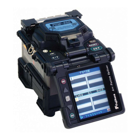
INSTRUCTION MANUAL
ARC FUSION SPLICER
F S M – 6 0 S
Please read this instruction manual carefully
before operating the equipment.
Adhere to all safety instructions and
warnings contained in this manual.
Keep this manual in a safe place.
Related Manuals for Fujikura FSM–60S
Summary of Contents for Fujikura FSM–60S
-
Page 1
INSTRUCTION MANUAL ARC FUSION SPLICER F S M – 6 0 S Please read this instruction manual carefully before operating the equipment. Adhere to all safety instructions and warnings contained in this manual. Keep this manual in a safe place. -
Page 3: Table Of Contents
Table of Contents Warning and Caution………….. 3 Introduction …………….9 Description of Product …………12 1. Components of Splicer ………………… 12 2. Other Necessary Items for Splicing Operation…………14 3. Description and Function of Splicer …………… 16 Point of the splice procedure……….20 1.
-
Page 4
Maintenance Menu …………… 92 1. Replace Electrodes………………..93 2. Stabilize Electrodes………………..94 3. Clear Arc Count………………….94 4. Battery Discharge ………………… 95 5. Set Calendar………………….96 6. Maintenance Info…………………. 96 7. Diagnostic Test Function………………97 8. Dust Check …………………… 98 9. -
Page 5: Warning And Caution
The splicer has been designed for splicing Silica-based optical fibers for telecommunications. Do not attempt to use this machine for other applications. Fujikura Ltd. gives much consideration and regard to personal injury. Misuse of the machine may result in electric shock, fire and/or serious personal injury.
-
Page 6
Warning and Caution WARNINGS Do not take the protector off the splicer, or consult your distributor for instruction. Tightening the original screw without the protector may damage mechanism inside. An environmental performance decreases when the protector is detached. -
Page 7
Warning and Caution WARNINGS Disconnect the AC power cord from the AC adapter inlet or the wall socket (outlet) immediately if user observes the following or if the splicer receives the following faults: • Fumes, bad smell, noise, or over-heat occurs. •… -
Page 8
When using an AC generator with AC output voltage of AC220-240V especially, Fujikura Ltd. recommends the following measures to correct the condition. (1) Connect a step-down transformer between the generator and the AC adapter in order to lower the AC voltage from AC220-240V to AC100-120V. -
Page 9
Warning and Caution WARNINGS Do not touch the splicer, AC power cord and AC plugs with wet hands. This may result in electric shock. Do not operate splicer near hot objects, in hot temperature environments, in dusty / humid atmospheres or when water-condensation is present on the splicer. This may result in electric shock, splicer malfunction or poor splicing performance. -
Page 10
Warning and Caution CAUTIONS Follow the below listed instructions for handling electrodes. • Use only specified electrodes. • Set the new electrodes in the correct position. • Replace the electrodes as a pair. Failure to follow the above instructions may cause abnormal arc discharge. It can result in equipment damage or degradation in splicing performance. -
Page 11: Introduction
Introduction Introduction The core alignment fusion splicer FSM-60S with PAS technology is designed for splicing many types of optical fibers. It is small in size and light in weight, making it suitable for any operating environment. It is easy to operate and it splices fast while maintaining low splice loss.
-
Page 12
To operate by the bad environment, the splicer has improved the performance. Dropping Water-Proof Dust Fujikura does not guarantee that the splicer will not be damaged under these conditions. Unique function (1) Automatic change of operating display The FSM-60S can be operated with monitor in front or at back. -
Page 13
Introduction (3) The fiber clamp release lever The fiber clamp arms are attached to wind protector and they close when wind-protector is closed. However, the fiber clamps can be detached by setting “clamp arm release lever” [UNLOCK]. This option can be recommended when fiber has some memory curl, so operator can make sure the fiber is surely clamped before wind-protector is closed. -
Page 14: Description Of Product
Description of Products Description of Product 1. Components of Splicer STANDARD SET Carrying Case AC Adapter / Battery Charger [ ADC-13 ] Arc Fusion Splicer [ FSM-60S ] Spare Electrodes AC Power Code 1 pair [ ELCT2-20A ] USB Cable [USB-01] J-Plate [ JP-04 ] Warnings and Cautions…
-
Page 15: Description Of Products
Description of Products 3.others DC power cord DC power cord [DCC-12] [DCC-13] Magnifier Battery Pack [MGS-05] [BTR-08] Battery charge cord [DCC-14]…
-
Page 16: Other Necessary Items For Splicing Operation
Description of Products 2. Other Necessary Items for Splicing Operation Fiber coating 0.25mm 0.9mm diameter Standard sleeve 60mm length [ FP-03 ] 40mm length [ FP-03 ( L = 40 ) ] Fiber protection sleeves Micro sleeve Micro sleeve 20mm length [ FPS01-250-20 ] 45mm length 25mm length [ FPS01-250-25 ] [ FPS01-900-45 ]…
-
Page 17
Description of Products Blank Page… -
Page 18: Description And Function Of Splicer
Description of Products 3. Description and Function of Splicer Wind protector Tube heater Protector USB port Protector HJS power port LCD monitor Protector Power unit dock A hole for tripod fixation (1/4”-20UNC and M8)
-
Page 19
Description of Products V-groove Electrode Objective lens Electrode cover Sheath clamp Sheath clamp Electrode cover Illumination lamp Electrode Wind protector Fiber clamp… -
Page 20
Description of Products RESET key SET key HEAT key Tube heater Wind protector ON/OFF key HEAT key Clamp arm release lever ARC key RESET key X/Y key SET key… -
Page 21
Description of Products Escape key Up/Down Arrow key Menu key Enter key LCD monitor… -
Page 22: Point Of The Splice Procedure
Point of the splice procedure Point of the splice procedure 1. To get a stable low splice loss 1-1. Daily cleaning before Splicing Operation • Clean the V-grooves. • Clean the wind protector mirrors. • Clean the Clamp Chips. • Clean Objective Lens every week, or when it’s dirty. In this case electrodes do not remove from the splicer.
-
Page 23
Point of the splice procedure 1-2. Select / use the suitable splice mode How to select the “Splice Mode” • When splicing only standard SM fibers (ITU-T G.652), “SM AUTO” mode is recommended. •When splicing many types of fibers, “AUTO” mode is recommended, but splice speed is slow. -
Page 24
Point of the splice procedure • Place fiber in the bottom of V-groove for successful splicing. No Good Good • Make sure if the cleave length is correct. Fiber coating edge may hit the V-groove in case with shorter cleave length, and then the fibers may not be stuffed each other during arc discharge and result in worse splice loss. -
Page 25
Point of the splice procedure • Check the fiber angle and cleave shape. The fiber cleave angle affects splicing quality. Large cleave angle worsens splice loss. Incline Chip •Visually check the arc discharge with the monitor. In case the arc discharge is observed “wobbling”… -
Page 26
Heating •Select the heater mode most suitable for the protection sleeve to be used. Each tube-heating mode is optimized for a type of Fujikura protection sleeve. Other manufacture’s fiber protection sleeve may not shrink completely. At that time extend the heating time. See page 80 [Heater Mode]. -
Page 27: Power Supply
Point of the splice procedure 2. Power Supply Use only supplied AC power cord. Connect to ground with ground terminal of AC power cord. 2-1. To prevent the damege of AC adpter AC generators may produce abnormally high AC output voltage or irregular frequencies. Such abnormally high voltage or frequency from a generator may cause fuming, electric shock or equipment damage and may result in personal injury, death or fire.
-
Page 28: Basic Operation
Basic Operation Basic Operation 1. How to use the work table on the carrying case The worktable can be attached / detached to the carrying case. • The splicer can not be attached to the work table without protector. (1) Detach the work table from the carrying case by loosen the screw. Remove (2) Tighten the screw behind the worktable to fix the splicer.
-
Page 29
Basic Operation (4) Holes on the worktable can be used to create your original work tray suitable for your unique splicing style. Hole Hole Hole • Arrange safety belts/devices for equipments and accessories on the tray before use. Straps for small accessories may be recommended. In case the equipment/accessories were dropped to a person under operation area, this would result in serious injury or fatal accident. -
Page 30: Inserting Power Supply To Splicer
Basic Operation 2. Inserting Power Supply to Splicer For AC operation or DC operation with external battery, use AC adapter (ADC-13). For battery operation, use detachable battery (BTR-08). The Power Unit Dock, located on the splicer body, can accommodate both power supplies (ADC-13 and BTR-08). 2-1.
-
Page 31
Basic Operation 2-3. DC operation with external battery Open shutter for DC inlet of AC adapter. • Do not supply DC16V or greater, the AC adapter will be damaged immediately. Open Plug DC cord (DCC-12 or DCC-13) into DC inlet of AC adapter. The ON LED turns on (green color) when suitable DC voltage is supplied. -
Page 32
Basic Operation 2-4. Battery operation Check and make sure the remaining battery capacity is 20% or greater before operation otherwise few splices can be made. • Fully discharge battery at least every three months, or the battery degrades due to memory effect. Seepage 95 for [Battery Discharge]. •… -
Page 33
Basic Operation READY screen Remaining battery capacity indicator Remaining battery capacity Remaining battery capacity Remaining display indicator battery 4 LED 75~100% (Blue Color) 3 LED 50~75% (Blue Color) 2 LED 25~50% (Yellow Color) 1 LED 10~25% (Red Color) 1 LED Flashing Less than 10% (Red Color) -
Page 34
Basic Operation How to charge battery Open shutter for battery charge plug inlet of the Battery Pack. Plug the supplied battery charge cord (DCC-14) into both the battery charge inlet of the AC adapter (ADC-13) and the battery charge terminal located on the battery (BTR-08) side. -
Page 35
Basic Operation • Do not place battery on top of AC adapter or vise-versa. • Battery can be charged while AC adapter (ADC-13) is in power unit dock of FSM-60S regardless of under operation or not. • CHARGE LED turns off when battery charge is completed. If CHARGE LED flashes, replace the battery with a new one. -
Page 36: Turning Splicer «On
Basic Operation 3. Turning splicer «ON» Press ON/OFF key and hold it until the green LED turns on. The following warning screen is displayed. • It is displayed in 3 per 1 month when turn the splicer power on. • There is the case that a language is fixed depending on the country of shipment.
-
Page 37
Basic Operation Monitor brightness READY Monitor visibility changes depending on environmental conditions. To change monitor brightness, press Up/Down Arrow key to change value and press Enter key to set value. Splice Mode Select appropriate splicing mode for the specific fiber combination. -
Page 38: Cleaning Optical Fiber
Basic Operation 4. Cleaning optical fiber Clean optical fiber with alcohol-impregnated gauze or lint-free tissue approximately 100mm from the tip. Dust particulates from the fiber coating surface can enter inside the protection sleeve and might result in a future fiber break or attenuation increase. 5.
-
Page 39
Basic Operation 6-2. Fiber holder System (1) Set the fiber onto the fiber holder with the fiber protruding 30 to 40mm from the end of the fiber holder and then close the fiber holder lid. • Close the lid of a fiber holder while pressing down with a finger on the coating (refer to figure below). -
Page 40: Fiber Cleaving
Basic Operation 7. Fiber Cleaving (1) To unlock the cutting lever, press it gently and slide the stopper. Cutting lever Stopper (2) Push the slide button until it locks. (3) Set the stripped optical fiber on the cleaver. • Confirm the sheath of fiber is not on pad when fiber holder is used. No Good Good (4) Press down the cutting lever.
-
Page 41
Basic Operation Fiber plate (AD-30A, AD-30B) Cutting lever Slide button (7) Close cutting lever completely then set stopper to lock the cutting lever closed. -
Page 42: Loading Fiber To Splicer
Basic Operation 8. Loading fiber to splicer 8-1. Sheath Clamp (1) Open wind protector and sheath clamps. (2) Place prepared fiber onto v-groove so that the fiber tip is located between the v-groove edge and tip of electrode. Electrode Sheath clamp •…
-
Page 43
Basic Operation 8-2. Fiber Holder System (1) Loosen a screw beside sheathe clamps and take the sheathe clamps off the splicer. (2) Open the wind protector. (3) Place fiber holders so that the guide pins on the stage go to guide-holes in the fiber. Fiber Guide Pins Fiber Holder… -
Page 44
Basic Operation The fiber clamp release lever The fiber clamp arms are attached to wind protector and they close when wind-protector is closed. However, the fiber clamps can be detached by setting “clamp arm release lever” [UNLOCK], then the fiber clamp can be moved independently. This option can be recommended when fiber has some memory curl, so operator can make sure the fiber is surely clamped before wind-protector is closed. -
Page 45: Splicing Procedure
Basic Operation 9. Splicing procedure To make a good splice, the optical fiber is observed with the image processing system equipped in the FSM-60S. However, there are some cases when the image processing system cannot detect a faulty splice. Visual inspection with the monitor is often necessary for better splicing yield.
-
Page 46
Basic Operation (3) After completion of fiber alignment, arc discharge is performed to splice the fibers. (4) Estimated splice loss is displayed upon completion of splicing. Splice loss is affected by certain factors stated in the next page. These factors are taken into account to calculate, or estimate, splice loss. -
Page 47
Basic Operation •When splicer indicates following message, splice loss may be high. “Arc discharge is not stable. Electrodes should be stabilized to reform the arc discharge.” Load prepared SM fibers onto splicer in order to stablize electrodes. After completeing it, re-splice fibers. When there is an environmental change (altitude), we recommend you to perform arc discharge proofreading. -
Page 48
Basic Operation Splice loss increase: Cause and remedy Symptom Cause Remedy Core axial offset Dust on v-groove or Clean v-groove and fiber clamp chip. fiber clamp chip Core angle Dust on v-groove or Clean v-groove and fiber clamp chip. fiber clamp chip Bad fiber end-face Check if fiber cleaver is well conditioned. -
Page 49
Basic Operation Symptom Cause Remedy Thin Arc power not Perform [Arc Calibration]. adequate Some arc parameters Adjust [Prefuse Power], [Prefuse Time] or not adequate [Overlap]. Line Some arc parameters Adjust [Prefuse Power], [Prefuse Time] or not adequate [Overlap]. • A vertical line sometimes appears at the splice point when MM fibers, or dissimilar fibers (different diameters) are spliced. -
Page 50: Removing Spliced Fiber
Basic Operation 10. Removing spliced fiber Hold left fiber with left hand at the (1) Open lids of tube heater. edge of the splicer. (2) Open wind protector. (3) Hold left fiber with left hand at the edge of wind Sheath Clamp protector and open left sheath clamp or fiber holder lid.
-
Page 51
Basic Operation (3) Then HEAT LED turn on and HEAT mark displayed on the monitor. HEAT Mark Heating: Cooling: • Tube heating does not start when heater lid is opening. • If HEAT key is pressed during tube heating, the HEAT LED blinks. If HEAT key is pressed again, the tube heating process is aborted. -
Page 52
Basic Operation (6) Attach the J-plate onto the splicer by installing aslant. (7) Remove the protected fiber from the splicer. •Do not touch the shrunken sleeve after removing the fiber from the tube heater. It may be hot. (8) Place the removed fiber into the J-plate. -
Page 53
Basic Operation When Magnifier MGS-05 is used. (1) Please extend both sides and insert from back. Please check that the nail is caught exactly. A screw is stopped. (2) A magnifying glass is fixed with an attached screw. (3) The assembled magnifying glass is fitted over a hole for a shaft like the following photograph. -
Page 54: Maintenance Of Splicing Quality
Maintenance of Splicing Quality Maintenance of Splicing Quality 1. Cleaning and Checking before Splicing Critical cleaning points and maintenance checks are described below. 1-1. Cleaning V-grooves If contaminants are present in the V-grooves, proper clamping may not occur, resulting in higher splice loss. The V-grooves should be frequently inspected and periodically cleaned during normal operation.
-
Page 55
Maintenance of Splicing Quality 1-2. Cleaning Fiber Clamp Chips Cotton swab If contaminants are present on the clamp chips, proper clamping may not occur, resulting in poor quality splices. The fiber clamp chips should be frequently inspected and periodically cleaned during normal operation. -
Page 56: Periodical Checking And Cleaning
Remove excess alcohol from the mirror surface with a clean dry swab. • Fujikura recommends to clean the objective lens when replace the electrode. • Remove electrode before cleaning objective lens.
-
Page 57
Blade lock screw Bottom view Adjuster lock screw Blade Replacement After the circular blade has been raised 3 times and rotated through all positions (a total of approximately 48,000 fiber splices), it needs to be replaced. Contact your Fujikura splicer distributor. -
Page 58
Maintenance of Splicing Quality 2-3. Replace Wind Protector Mirrors Replace the wind protector mirror if it cannot be cleaned or if it remains clouded. To replace, do the following: (1) Turn the splicer power off. (2) Open the wind protector. Pull and unlock wind protector mirror latch with fingers. While still pulling on mirror latch, use other hand’s fingers to pull on wind protector mirror frame. -
Page 59
Maintenance of Splicing Quality (4) Clean Wind Protector Mirrors. (5) Turn on the power and make sure no smudges or streaks are visible on the monitor screen. Press X/Y key to change the screen and check the state of the lens surface on both the X- and Y-screens. -
Page 60: Splice Menu
Splice Menu Splice Menu 1. Splice Mode The optimum splice setting for a specific fiber combination consists of the below listed splicing parameters. In other words, the optimum splicing parameters depend on the fiber combinations, and are different from fiber to fiber. Parameters for controlling arc discharge / heating.
-
Page 61
Splice Menu Database Splice Mode Description This splice mode observes the core profile of the optical fiber, and automatically identifies the fiber type being SM, MM or NZDS. A set of splicing parameters is selected for the identified fiber type and the fibers are automatically spliced. -
Page 62
Splice Menu Splice Mode Description For splicing standard Single-mode fiber (ITU-T G652). The MFD is 9 to 10 um at wavelength of 1310 nm. Automatic arc calibration doesn’t work in this splice mode. For splicing Non-zero dispersion-shifted fiber (ITU-T G655). The MFD is 9 to 10 um at wavelength of 1550 nm. -
Page 63
Splice Menu 1-1. Splice mode selection Select an appropriate splice mode for type of fiber to be spliced. (1) Press Menu key at [READY], [PAUSE1], [PAUSE2] or [FINISH] state to open [Splice Menu]. Select [Select Splice Mode] and the [Select Splice Mode] menu is displayed. -
Page 64
Splice Menu 1-2. Creating or erasing splice mode How to create splice mode There are 8 splice modes stored when the splicer is first delivered, and all the other modes are displayed [BLANK]. Follow the below steps to add splice mode. Select a “BLANK”… -
Page 65
Splice Menu 1-3. Referring or editing splice mode Splicing parameters in each splice mode can be Select Splice Mode Menu modified. Arc power and Arc time are considered the two most vital parameters. To edit parameters UP/DOWN Arrow key follow below steps: Menu key (1) In [Select Splice Mode] menu, move cursor to a splice mode to be modified. -
Page 66
Splice Menu Below is a list of Splicing parameters for AUTO modes AUTO mode : [AUTO], [SM AUTO] , [MM AUTO] , [NZ AUTO] , [DS AUTO] Only a limited number of parameters listed below are displayed for AUTO, SM, DS, MM and NZ modes to simplify the operation. -
Page 67
Splice Menu Splicing parameters: standard modes Standard mode : [SM], [MM], [NZ], [DS] In other splice modes in the user-selectable database, the user can select one from a series of factory-set splicing modes for various splicing combinations. Below are the descriptions of the various parameters used in these modes. -
Page 68
Splice Menu Parameter Description An error message is displayed if the cleave angle of either the left or right Cleave Limit fiber ends exceed the selected threshold (cleave limit). An error message is displayed if the estimated splice loss exceeds the Loss Limit selected threshold (loss limit). -
Page 69
Core curve and MFD mismatch are automatically set «OFF». If the estimated splice on certain fiber combinations needs adjustment, Core step, Core curve and MFD mismatch are used. These are advanced Mismatch splicer functions and should be discussed with your Fujikura representative before changing. -
Page 70
Splice Menu 1-4. How to input Mode Title / Comment / Password Character list below is displayed by selecting Mode Title / Comments / Password. (1) Move the cursor by pressing Up/Down Arrow key, Menu key, and press Enter key to input the selected character. -
Page 71
Splice Menu 1-5. Manual Splice Mode This mode is to manually align and splice fibers. The following procedure is required, and is different from standard automatic splicing. (1) Press SET key to drive the fibers forward. The fibers stop moving forward at the Gapset position. -
Page 72
Splice Menu 1-6. ECF Splice When fibers having some core concentricity-error are aligned using the core-to-core method, their outer claddings are not aligned in line with each other as shown below. However, surface tension created during arc discharge aligns the fibers cladding-to-cladding due to the viscous self-centering effect. -
Page 73
Splice Menu 1-7. Attenuation splice mode Attenuation splice mode makes an intentional core axial offset to create attenuation at the splice point. Two types of attenuation splice modes are included in the splicer as stated below. Select either «AT1(SM)», «AT1(DS)», «AT2(SM)», «AT2(DS) or AT2(MM) in data base area at [Fiber Type]. -
Page 74
Splice Menu • [AT2] mode provides more stable performance than [AT1] mode, but some variation may inevitably occur. To decrease variation, set the [Cleave Limit] as low as possible. • Attenuation splices made with [AT1] / [AT2] modes are not as accurate as power meter attenuation feedback splicing. -
Page 75: Splice Option
Splice Menu 2. Splice Option Common parameters for all the modes for splicing and tube heating can be set. (1) Press Menu key at [READY], [PAUSE1], [PAUSE2] or [FINISH] state to open [Splice Menu]. (2) Select a parameter to be changed. (3) Press Enter key to change values.
-
Page 76: Splice Memory
Splice Menu 3. Splice Memory This splicer stores up to 2,000 splicing results. Contents of data stored are different depending on splicing mode. No results are stored for «attenuation splicing». SM / NZ / DS / MM / AUTO Others…
-
Page 77
Splice Menu 3-1. List of Splice Results Splicing results stored in the memory can be displayed. Comments can be added or edited. • Memory Data can be download by USB. Refer to instruction manual of “FSM Data Connection”. How to display the splice Result data (1) Select [Memory] in [Splice Menu]. -
Page 78
Splice Menu How to Clear the Splice Results data (1) Press Menu key in [Splice Result] Menu. (2) Press Menu key in [Jump / Remove] Menu. (3) The memory can be deleted by pushing Enter key again. (4) Select the memory of beginning of the range that wants to delete by Enter key. (5) Select the memory of ending of the range that wants to delete by Up/Down arrow key. -
Page 79
Splice Menu 3-2. Splice Result of Error Only splice result with the error is sorted out among Splice Result and displayed. The method of the display and the deletion is the same as ”List of Splice Results”. Enter key Menu key 3-3. -
Page 80
Splice Menu 3-4. Camera Image This function is to store the fiber image after splice or error occurred. Total 8 images can be stored. (1) Select [Memory] in [Splice Menu]. (2) Select [Camera Image] and press Enter key to display [Camera Image] Menu. Ho to store the Camera Image Data Select [No Image] by moving cursor to a specific memory number and press Enter key. -
Page 81: Splice Memory Comment
Splice Menu Ho to display Camera Image Data Select memory number by moving cursor to a specific memory number and press Enter key. The fiber image data is displayed. Select Memory number Enter key Enter key Ho to delete Camera Image Data Select the number in [Camera Image] and press the Menu key.
-
Page 82: Heater Menu
There are 30 user-programmable heating modes. Select one best suitable for the protection sleeve used. Each tube-heating mode is optimized for a type of Fujikura protection sleeve. These modes can be found in database area for reference. Copy the appropriate one and paste it to the user-programmable area.
-
Page 83
Heater Menu 1-1. Selecting Heater mode Select the heater mode most suitable for the protection sleeve to be used. (1) Press Menu key in [READY], [PAUSE1], [PAUSE2], [FINISH] state and press Menu key to display [Heater Menu]. Splice Menu Heater Menu Menu key (2) Select [Select Heater Mode] in [Heater Menu]. -
Page 84
Heater Menu 1-2. ferring or editing Heater Mode Tube-heating conditions stored in heater mode can be edited or changed. (1) Move cursor and select a mode to be edited in [Select Heater Mode] menu. Press Menu key to display [Edit Heater Mode] menu. (2) Press Up/Down Arrow keys to move cursor to a parameter to be changed, then press Enter key to enter. -
Page 85: Auto Start
Heater Menu Heater mode parameters Parameter Description Sets sleeve type. List of all heating modes are displayed. Select a mode Sleeve type in the list and this is copied to a user-programmable mode. Title of a heater mode that is displayed in the lower right part of the Mode Title1 monitor during the splicing/heating process.
-
Page 86: Setting Menu
Setting Menu Setting Menu 1. Splice Settings Common parameters for all the modes for splicing can be set. (1) Press Menu key in [READY], [PAUSE1], [PAUSE2], [FINISH] state and press Menu key to display [Setting Menu]. Splice Menu Setting Menu Menu key (2) Select [Splice Settings] in [Setting Menu] to display [Splice Settings] menu.
-
Page 87
Setting Menu Parameter Description Ignore Splice Error Loss Bubble Setting to “Disable” prevents the splicer from normally finishing its operation even if the message “Loss Error,” “Bubble Error,” “Fat Error” “Thin Error” or “Fiber Angle Error” is disregarded. Thin Fiber Angle Setting to “Disable”… -
Page 88: Maintenance Settings
Setting Menu 2. Maintenance Settings Available to set the parameters about warning and maintenance item. Electrode When the number of splices made exceeds 1,000, the caution Electrode Caution message prompting for electrode replacement is displayed when the power is turned on. When the number of splices exceeds 2,000, the caution message changes to the warning message.
-
Page 89: Machine Settings
Setting Menu 3. Machine Settings (1) Select [Machine Settings] in [Setting Menu]. (2) Select a parameter to be changed. Machine Settings Enter key Select the [Machine Settings] in the [Setting Menu] Parameter Description Sets a language to be displayed on the screen. Select a language to be displayed.
-
Page 90
Setting Menu 3-1. Change of Operating Direction The splicer is shipped from the factory with settings for the “Monitor Front” operation style. This can be changed to “Monitor Rear” operation style. The sheath clamp direction can also be changed for the selected style. When [Monitor Position] is changed, the direction of the four arrow keys is reversed. -
Page 91
Setting Menu 3-2. Power Save function in Machine Settings This function is important for energy conservation. If the power saving function is not set during battery pack use, the number of splice cycles will be decreased. The splicer automatically identifies the type of power supply unit. In addition, it can program an independent power saving setting. -
Page 92
Setting Menu 3-3. Power On Option in Machine Settings Set Opening title and Password Lock function Parameter Descriptions Sets the message to be displayed when the power is turned on. Opening Title1 Max. number of characters : 15 (Opening Title1) 15 (Opening Title2) Opening Title2 To edit Title, see page [Title] on how to input title. -
Page 93: Menu Lock Settings
Setting Menu 4. Menu Lock Settings (1) Select [Menu Lock Settings] in the [Setting Menu]. Password input screen is displayed. (2) Input Password. See page 68 [How to input Mode Title / Comment / Password] on how to input password. (3) Change a parameter value.
-
Page 94: Maintenance Menu
Maintenance Menu Maintenance Menu The splicer has the ability to perform routine maintenance. This section describes how to use the maintenance menu. (1) Press Menu key in [READY], [PAUSE1], [PAUSE2], [FINISH] state. Press Menu key to display [Maintenance Menu1], [Maintenance Menu2]. (2) Select a function to perform.
-
Page 95: Replace Electrodes
Maintenance Menu 1. Replace Electrodes It is recommended that the electrodes be replaced after 1,000 arc discharges. When the number of arc discharges reaches a count of 2,000, a message prompting to replace the electrodes is displayed immediately after turning on the power. Using the electrodes without a replacement will result in greater splice loss and reduced splice strength.
-
Page 96: Stabilize Electrodes
Maintenance Menu (5) Turn on the power, prepare and load fibers into the splicer and press Enter key. After executing the arc calibration, the splicer will repeat arc discharge 45 times in succession to stabilize the electrodes. (6) Upon completion of repeated arc discharge, the splicer executes an arc calibration again.
-
Page 97: Battery Discharge
Maintenance Menu 4. Battery Discharge The battery pack (BTR-08) uses Ni-MH cells. If the battery pack is recharged repeatedly even though a sufficient capacity still remains, a memory effect would make it seem as if the battery capacity has decreased. If such a phenomenon occurs, execute [Battery Discharge] to reduce the remaining capacity to zero.
-
Page 98: Set Calendar
Maintenance Menu 5. Set Calendar This function sets the date and time in the calendar incorporated in the splicer. Operation Procedure (1) Select the [Set Calendar]. (2) As the year, month, day and time are displayed, press Menu key to move the cursor to the parameters, and press Up/Down Arrow key to adjust numerical values.
-
Page 99: Diagnostic Test Function
Maintenance Menu 7. Diagnostic Test Function The FSM-60S has a built in diagnostic test feature that allows the operator to perform a simple one step evaluation of splicer performance covering several different critical variables. Perform this function in the event of splicer operation trouble. Operation Procedure (1) Select the [Diagnostic Test] in the [Maintenance Menu 2] and execute [Diagnostic Test].
-
Page 100: Dust Check
Maintenance Menu 8. Dust Check The splicer observes fibers through image processing. Dust or contaminants on the cameras, lenses and wind protector mirrors disturbs normal observation of fibers and may result in improper splicing. This function checks the optical path for the presence or absence of contaminants and judges whether they cause trouble for fiber splicing.
-
Page 101: Arc Calibration
Maintenance Menu 9. Arc Calibration Atmospheric conditions such as temperature, humidity, and pressure are constantly changing, which creates variability in the arc temperature. This splicer is equipped with temperature and pressure sensors that are used in a constant feedback monitoring control system to regulate the arc power at a constant level.
-
Page 102
Maintenance Menu • Cleave angle threshold does not link to the parameter «Cleave Limit» in splicing modes. Cleave angle threshold is independently set for arc calibration. See page 84 [Splice Settings] to change cleave angle threshold. “Good” message Arc power and splicing position calibration are successfully completed. Press Escape key to exit. -
Page 103: Motor Calibration
Maintenance Menu 10. Motor Calibration Motors were adjusted at the factory before shipping. However, settings could change due to various reasons. This function automatically calibrates the speed of all six motors. Operation Procedure (1) Select the [Motor Calibration] in the [Maintenance Menu 2]. (2) Load prepared fibers in the splicer and press Enter key.
-
Page 104: Error Message List
Error Message List Error Message List Press Enter when an error is shown on the monitor. The [HELP] screen displays the following: • If error does not have an error code, such as “Cleave Shape NG”, the keystrokes are displayed with information explaining what each keystroke does if pressed. •…
-
Page 105
Error Message List Error Reason Solution Message • Dust or dirt is on the •Completely prepare the fiber again (strip, fiber surface. clean and cleave). L-Too Dusty • Dust or dirt is on the • Execute the [Dust Check]. Clean the lens or Fiber objective lens or the the mirror if dust or dirt exists. -
Page 106
Error Message List Error Reason Solution Message • The fiber is set too far • Press RESET key, re-position the fiber again back and does not reach ZL Motor with the end-face closer to the electrodes. the splice point. Overrun (Forward) •… -
Page 107
Error Message List Error Reason Solution Message Focus X • The fiber is not set Motor correctly at the bottom • Press RESET key, and re-position the fiber Overrun of the V-groove. The again to seat it correctly at the bottom of the (Forward) fiber position is out of V-groove. -
Page 108
Error Message List Error Reason Solution Message Completely prepare the fiber again (strip, Dust or dirt is on the clean and cleave). fiber surface. Select the suitable splice mode. Pressing the Cannot detect fiber in The left and right fiber SET key cancels the error and continues the AUTO mode types are different. -
Page 109
Error Message List Error Reason Solution Message Bad fiber Check the condition of the fiber cleaver. If the blade is Large end-face. worn, rotate the blade to a new position. Cleave [Cleave Limit] is Angle Increase the [Cleave Limit] to an adequate limit. set too low. -
Page 110
Error Message List Error Reason Solution Message Dust or dirt on the fiber surface results in bad splice loss and low tensile strength. Insufficient fiber • Clean the fiber surface sufficiently. cleaning. • Do not clean the fiber after cleaving to prevent dust on the fiber end-face. -
Page 111
Error Message List Error Message Reason Solution • Clean the wind protector mirrors by referring page 53. If it is not possible to remove the dirt There is dust or dust on the mirror, replace the wind after executing Dirt or dust exists protector mirror by referring page 56. -
Page 112: Questions And Troubleshooting
Questions and Troubleshooting Questions and Troubleshooting 1. Power Supply (1) Power does not turn off when pressing ON/OFF key • Press and hold the key until the LED color changes from green to red. (2) Few splices can be made with a fully charged battery pack •…
-
Page 113: Splicing Operation
Questions and Troubleshooting 2. Splicing Operation (1) Error message appears on monitor • See page 102 [Error Message List]. (2) Inconsistent splice loss / High splice loss • Clean the V-grooves, fiber clamps, wind protector mirrors, and objective lenses. See page 52 [Maintenance of Splicing Quality].
-
Page 114
Questions and Troubleshooting (8) Error message can be over-ridden • See page 84 [Splice Settings] to not allow error message override. (9) Unable to change Arc Power and Arc Time • The settings cannot be changed in SM, NZ, MM or AUTO modes. •… -
Page 115: Tube-Heating Operation
Questions and Troubleshooting 3. Tube-heating Operation (1) Fiber protection sleeve does not shrink completely • Extend the heating time. See page 80 [Heater Mode]. (2) Heater LED on panel keyboard blinks • Pressing the HEAT key during heating causes the LED to blink. The tube heater is turned off if the HEAT key is pressed again.
-
Page 116: Other Functions
Questions and Troubleshooting 5. Other Functions (1) Method to hide messages on [READY] screen • Change the fiber image from X/Y view to X magnified view or Y magnified view by pressing X/Y key. (2) Too many repetitions until “Test Finish” indicated in [Arc Calibration] •…
-
Page 117
Questions and Troubleshooting Blank Page… -
Page 118: Guarantee And Contact Address
The specification of AC input voltage is up to AC240V (340V-peak). For this reason, Fujikura Ltd. will provide a warranty replacement of the AC adapter only one time. In a second AC adapter is damaged during the warranty period, Fujikura Ltd.
-
Page 119: Contact Address
Guarantee and Contact Address 7. Contact Address Inquiries concerning products should be made to the distributor or one of the following: Fujikura Europe Ltd. C51 Barwell Business Park Leatherhead Road, Chessington, Surrey KT9 2NY England Tel. +44-20-8240-2000 (Service: +44-20-8240-2020) Fax.
- Вся активность
Русский мануал на Fujikura FSM-60S
очень надо
Join the conversation
You can post now and register later.
If you have an account, sign in now to post with your account.
Maintenance Menu ……………………………………………………… 92
1. Replace Electrodes………………………………………………………………………………………. 93
2. Stabilize Electrodes……………………………………………………………………………………… 94
3. Clear Arc Count………………………………………………………………………………………….. 94
4. Battery Discharge ……………………………………………………………………………………….. 95
5. Set Calendar……………………………………………………………………………………………….. 96
6. Maintenance Info………………………………………………………………………………………… 96
7. Diagnostic Test Function……………………………………………………………………………… 97
8. Dust Check …………………………………………………………………………………………………. 98
9. Arc Calibration …………………………………………………………………………………………… 99
10. Motor Calibration …………………………………………………………………………………… 101
11. Motor Drive …………………………………………………………………………………………….. 101
Error Message List …………………………………………………….. 102
1. Power Supply ……………………………………………………………………………………………..110
2. Splicing Operation………………………………………………………………………………………111
3. Tube-heating Operation ………………………………………………………………………………113
4. Supervising…………………………………………………………………………………………………113
5. Other Functions ………………………………………………………………………………………….114
6. Guarantee…………………………………………………………………………………………………..116
7. Contact Address………………………………………………………………………………………….117
2
|
Detail Specifications: 663/663710-fsm60s.pdf file (05 Jan 2023) |
Accompanying Data:
Fujikura FSM–60S Welding System PDF Instruction Manual (Updated: Thursday 5th of January 2023 04:47:14 AM)
Rating: 4.8 (rated by 32 users)
Compatible devices: KSP75-FP-005468, 90S, FSM–40S, Commander 500 Cummins, MIG 130 A, CB-08, 62S, 320.
Recommended Documentation:
Text Version of Instruction Manual
(Ocr-Read Summary of Contents, UPD: 05 January 2023)
-
19, 17 Description of Products V-groove Sheath clamp Electrode Electrode cove r Illumination lamp Electrode Electrode cove r Sheath clamp Objective lens Wind protector Fiber clam p
… -
35, 33 Basic Operation • Do not place battery on top of AC adapter or vise-versa. • Battery can be charged while AC adapter (ADC-13) is in power unit dock of FSM-60S regardless of under operation or not. • CHARGE LED turns off when battery charge is completed. If CHARGE LED flashes, replace the battery with a new one. • If battery charge does not complete in five hours or CHAR…
-
100, Fujikura FSM–60S 98 Maintenance Menu 8. Dust Check The splicer observes fibers through image processing. Dust or contaminants on the cameras, lenses and wind protector mirrors disturbs normal observation of fibers and may result in improper splicing. This function checks the optical path for the presence or absence of contaminants and judges whether they cause trouble for fiber splicing. …
-
30, Fujikura FSM–60S 28 Basic Operation 2. Inserting Power Supply to Splicer For AC operation or DC operation with external battery, use AC adapter (ADC-13). For battery operation, use detachable battery (BTR-08). The Power Unit Dock, located on the splicer body, can accommodate both power supplies (ADC-13 and BTR-08). 2-1. Inserting or detaching power unit Inserting …
-
109, 107 Error Message List Error Message Reason Solution Bad fiber end-face. Check the condition of the fiber cleaver. If the blade is worn, rotate the blade to a new position. Large Cleave Angle [Cleave Limit] is set too low. Increase the [Cleave Limit] to an adequate limit. [Core Angle Limit] is set too low. The splicer measures the core angle …
-
85, 83 Heater Menu Heater mode parameters Parameter Description Sleeve type Sets sleeve type. List of all heating modes are displayed. Select a mode in the list and this is copied to a user-programmable mode. Mode Title1 Title of a heater mode that is displayed in the lower right part of the monitor during the splicing/heating process. Max number of characters used is 5. Mode Tit…
-
49, Fujikura FSM–60S 47 Basic Operation Symptom Cause Remedy Arc power not adequate Perform [Arc Calibration]. Thin Some arc parameters not adequate Adjust [Prefuse Power], [Prefuse Time] or [Overlap]. Line Some arc parameters not adequate Adjust [Prefuse Power], [Prefuse Time] or [Overlap]. Storing splicing results Splicing results is stored in memory. The spl…
-
69, 67 Splice Menu Parameter Description Arc2 Power Arc2 is the second arc discharge stage. This sets Arc2 Power. Arc2 Time Sets the total Arc2 time. Usually set this value to “OFF”. It is possible to set a very long arc time. However, when the total of the Arc 1 time and Arc2 time exceeds 30 seconds, always adjust the function [Arc2 ON Time] and [Arc2 OFF Time] to we…
-
59, 57 Maintenance of Splicing Quality (4) Clean Wind Protector Mirrors. (5) Turn on the power and make sure no smudges or streaks are visible on the monitor screen. Press X/Y key to change the screen and check the state of the lens surface on both the X- and Y-screens. Perform dust check. 2-4. Electrode Replacement See page 93 [Replace Electrodes]. 2-5. …
-
93, 91 Setting Menu 4. Menu Lock Settings (1) Select [Menu Lock Settings] in the [Setting Menu]. Password input screen is displayed. (2) Input Password. See page 68 [How to input Mode Title / Comment / Password] on how to input password. (3) Change a parameter value. Used for Administrator to limit operator from selecting or changing certain functions. Parame…
Recommended Instructions:
LS236LS, EOS 400D, IQ-5100, SC-VC80B91, TV-IP450P


-
Operating manual • EnglishKäyttöohje • SuomiBruksanvisning • SvenskaBruksanvisning • NorskBrugsanvisning • DanskGebrauchsanweisung • DeutschGebruiksaanwijzing • NederlandsManuel d’utilisation • FrançaisИнструкции по эксплуатации • По-русскиENFISVNODADENLFRRUKempoweldWIRE 400, 550 …
WIRE 400 24
-
RANGER®3 PHASE$%’)$’V(»#*!For Machines with Code Number 11619»November, 2010(165DI[email protected]>4C?>.?ELincoln arc welding and cuttingequipment is designed and builtwith safety in mind. However,your overall safety can beincreased by proper installation …and thoughtful operation on yourpart.DO NOT I NST AL …
RANGER 3 PHASE 36
-
© 2016 Nelson Stud Welding, Inc. Page 1 All Rights Reserved. February 2016 Part No. 729-110-042 v1.03 NCD+ Auto-Gap Gun Instruction & Maintenance Manual (729-110-042) These instructions are intended for experienced operators. If you are not fully familiar with the principles of operation and safe practices for arc welding equipment, we urge you to read AWS SP � …
NCD+ Auto-Gap Gun 29
-
INSTRUCTION MANUALPCM-875PLASMA ARC CUTTING PACKAGEF15-335-E July, 2007These INSTRUCTIONS are for experienced operators. If you are not fully familiar with the principles of operation andsafe practices for arc welding and cutting equipment, we urge you to read our booklet, «Precautions and SafePractices for Arc Welding, Cutting, and Gouging,» Form 52-529. …
PCM-875 48
Additional Information:
Popular Right Now:
Operating Impressions, Questions and Answers:
Table of Contents for Fujikura FSM–60S:
-
16 Description of Products 3. Description and Function of Splicer Tube heate r LCD monito r HJS p ower p or t Power unit dock USB port Wind p rotecto r A hole for tripod fixation ( 1/4”-20UNC and M8 ) Protecto r Protecto r Protecto r
-
66 Splice Menu Parameter Description Cleave Limit An error message is displayed if the cleave angle of either the left or right fiber ends exceed the selected threshold (cleave limit). Loss Limit An error message is displayed if the estimated splice loss exceeds the selected threshold (loss limit). Fiber Angle Limit An error message is displayed if the bend angle of the two fibers spliced exceeds the selected threshold (Fiber Angle Limit). Cleave Shape Error Error message is displaye
-
39 Basic Operation (7) Close cutting lever completely then set stopper to lock the cutting lever closed. Li d Sli d e button Cutting lever F ib er p l ate (AD-30A, AD-30B)
-
87 Setting Menu 3. Machine Settings (1) Select [Machine Settings] in [Setting Menu]. (2) Select a parameter to be changed. Parameter Description Language Sets a language to be displayed on the screen. Select a language to be displayed. The language that can be displayed changes by a software version and region code. Buzzer Volume Sets the sound volume of the buzzer. Monitor Position Sets the operational directi
-
78 Splice Menu 3-4. Camera Image This function is to store the fiber image after splice or error occurred. Total 8 images can be stored. (1) Select [Memory] in [Splice Menu]. (2) Select [Camera Image] and press Enter key to display [Camera Image] Menu. Ho to store the Camera Image Data Select [No Image] by moving cursor to a specific memory number and press Enter key. The fiber image data is stored. Ent
-
27 Basic Operation (4) Holes on the worktable can be used to create your original work tray suitable for your unique splicing style. Hole Hole Hole • Arrange safety belts/devices for equipments and accessories on the tray before use. Straps for small accessories may be recommended. In case the equipment/accessories were dropped to a person under operation area, this would result in serious injury or fatal acciden
-
50 Basic Operation (6) Attach the J-plate onto the splicer by installing aslant. (7) Remove the protected fiber from the splicer. (8) Place the removed fiber into the J-plate. (9) Leave the fiber in the J-plate until the shrunken sleeve is cooled down. •Do not touch the shrunken sleeve after removing the fiber from the tube heater. It may be
-
46 Basic Operation Splice loss increase: Cause and remedy Symptom Cause Remedy Core axial offset Dust on v-groove or fiber clamp chip Clean v-groove and fiber clamp chip. Dust on v-groove or fiber clamp chip Clean v-groove and fiber clamp chip. Core angle Bad fiber end-face quality Check if fiber cleaver is well conditioned. Core step Dust on v-groove or fiber clamp chip Clean v-groove and fiber clam
-
29 Basic Operation 2-3. DC operation with external battery Open shutter for DC inlet of AC adapter. Plug DC cord (DCC-12 or DCC-13) into DC inlet of AC adapter. The ON LED turns on (green color) when suitable DC voltage is supplied. In case DC16V or greater is supplied, or polarity (positive / negative) is wrong, The AC adapter protection circuit shuts down the DC output and DC Warning LED [HIGH ~ INPUT] turns on (red color). • Do not supply DC16V or greater, the AC
-
83 Heater Menu Heater mode parameters Parameter Description Sleeve type Sets sleeve type. List of all heating modes are displayed. Select a mode in the list and this is copied to a user-programmable mode. Mode Title1 Title of a heater mode that is displayed in the lower right part of the monitor during the splicing/heating process. Max number of characters used is 5. Mode Title2 Description of
-
117 Guarantee and Contact Address 7. Contact Address Inquiries concerning products should be made to the distributor or one of the following: Fujikura Europe Ltd. C51 Barwell Business Park Leatherhead Road, Chessington, Surrey KT9 2NY England Tel. +44-20-8240-2000 (Service: +44-20-8240-2020) Fax. +44-20-8240-2010 (Service: +44-20-8240-2029) URL http://www.fujikura.co.uk AFL Telecommunications 260
-
44 Basic Operation (3) After completion of fiber alignment, arc discharge is performed to splice the fibers. (4) Estimated splice loss is displayed upon completion of splicing. Splice loss is affected by certain factors stated in the next page. These factors are taken into account to calculate, or estimate, splice loss. The calculation is
-
102 Error Message List Error Message List Press Enter when an error is shown on the monitor. The [HELP] screen displays the following: • If error does not have an error code, such as “Cleave Shape NG”, the keystrokes are displayed with information explaining what each keystroke does if pressed. • If error has an error code, additional information according to the Error Code and Message is displayed. Follow the solution precisely as shown in the list below. If it is not possible to eliminate the problem,
-
54 Maintenance of Splicing Quality 2. Periodical Checking and Cleaning In order to maintain the splicing quality of the splicer, periodical inspection and cleaning are recommended. 2-1. Cleaning Objective Lenses If the objective lens’s surface becomes dirty, normal observation of the core position may be incorrect, resulting in higher splice loss or poor splicer operation. Therefore, clean both of them at regular intervals. Otherwise, dirt may accumulate and become impossible to remove. To clean the objective lenses, do the following: (1
-
9 Introduction Introduction The core alignment fusion splicer FSM-60S with PAS technology is designed for splicing many types of optical fibers. It is small in size and light in weight, making it suitable for any operating environment. It is easy to operate and it splices fast while maintaining low splice loss. In order to achieve the splicer’s full capabilities, read the following important information. Splice mode Use [SM]
Questions, Opinions and Exploitation Impressions:
You can ask a question, express your opinion or share our experience of Fujikura FSM–60S device using right now.