- Manuals
- Brands
- Gigabyte Manuals
- Motherboard
- GA-970A-DS3
- User manual
Manual
-
Contents
-
Table of Contents
-
Bookmarks
Quick Links
GA-970A-DS3
User’s Manual
Rev. 1001
12ME-970ADS3-1001R
Related Manuals for Gigabyte GA-970A-DS3
Summary of Contents for Gigabyte GA-970A-DS3
-
Page 1
GA-970A-DS3 User’s Manual Rev. 1001 12ME-970ADS3-1001R… -
Page 3: Identifying Motherboard Revision
GIGABYTE’s prior written permission. Documentation Classifications In order to assist in the use of this product, GIGABYTE provides the following types of documentations: For quick set-up of the product, read the Quick Installation Guide included with the product.
-
Page 4: Table Of Contents
Table of Contents GA-970A-DS3 Motherboard Layout …………….5 GA-970A-DS3 Motherboard Block Diagram …………..6 Chapter 1 Hardware Installation ………………7 Installation Precautions ………………7 Product Specifications ………………8 Installing the CPU ………………10 Installing the Memory ………………11 Installing an Expansion Card …………….. 11 Back Panel Connectors ………………
-
Page 5: Ga-970A-Ds3 Motherboard Layout
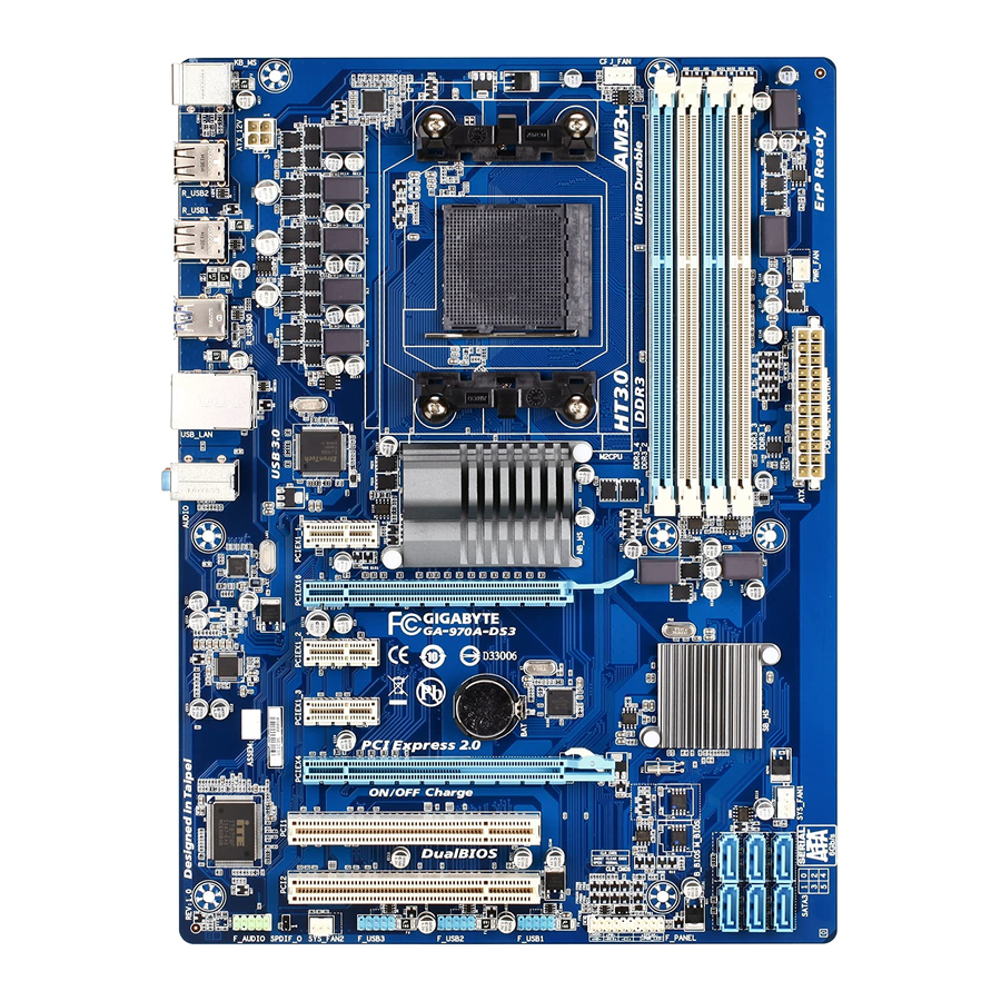
GA-970A-DS3 Motherboard Layout CPU_FAN KB_MS ATX_12V R_USB2 Socket AM3+ R_USB1 PWR_FAN R_USB30 USB_LAN Etron EJ168 AUDIO AMD 970 PCIEX1_1 (Note) Realtek GbE LAN PCIEX16 GA-970A-DS3 PCIEX1_2 CODEC PCIEX1_3 AMD SB950 PCIEX4 SYS_FAN1 M_BIOS PCI1 B_BIOS PCI2 SATA3 0 2 4…
-
Page 6: Ga-970A-Ds3 Motherboard Block Diagram
GA-970A-DS3 Motherboard Block Diagram CPU CLK+/- (200 MHz) DDR3 2000 (O.C.)/1866/1600/ AM3+/AM3 CPU 1333/1066 MHz 1 PCI Express x16 Dual Channel Memory Hyper Transport Bus PCIe CLK (100 MHz) 2 USB 3.0/2.0 3 PCI Express x1 RJ45 Realtek Etron GbE LAN…
-
Page 7: Chapter 1 Hardware Installation
Chapter 1 Hardware Installation Installation Precautions The motherboard contains numerous delicate electronic circuits and components which can become damaged as a result of electrostatic discharge (ESD). Prior to installation, carefully read the user’s manual and follow these procedures: Prior to installation, make sure the chassis is suitable for the motherboard. •…
-
Page 8: Product Specifications
Support for DDR3 2000(O.C.)/1866/1600/1333/1066 MHz memory modules Š * To support a DDR3 1866 MHz (and above) memory, you must install an AM3+ CPU first. (Go to GIGABYTE’s website for the latest supported memory speeds and memory modules.) Audio Realtek HD audio codec Š…
-
Page 9
Operating Support for Microsoft Windows 7/Vista/XP Š ® System Form Factor ATX Form Factor; 30.5cm x 22.5cm Š * GIGABYTE reserves the right to make any changes to the product specifications and product-related information without prior notice. — 9 -… -
Page 10: Installing The Cpu
Read the following guidelines before you begin to install the CPU: Make sure that the motherboard supports the CPU. • (Go to GIGABYTE’s website for the latest CPU support list.) Always turn off the computer and unplug the power cord from the power outlet before installing the •…
-
Page 11: Installing The Memory
Make sure that the motherboard supports the memory. It is recommended that memory of the same • capacity, brand, speed, and chips be used. (Go to GIGABYTE’s website for the latest supported memory speeds and memory modules.) Always turn off the computer and unplug the power cord from the power outlet before installing the •…
-
Page 12: Back Panel Connectors
Back Panel Connectors PS/2 Keyboard/Mouse Port Use this port to connect a PS/2 mouse or keyboard. USB 2.0/1.1 Port The USB port supports the USB 2.0/1.1 specification. Use this port for USB devices such as a USB keyboard/mouse, USB printer, USB flash drive and etc. USB 3.0/2.0 Port The USB 3.0 port supports the USB 3.0 specification and is compatible to the USB 2.0/1.1 specification.
-
Page 13: Internal Connectors
Internal Connectors ATX_12V SATA3 0/1/2/3/4/5 CPU_FAN F_PANEL SYS_FAN1/SYS_FAN2 F_AUDIO PWR_FAN SPDIF_O CLR_CMOS F_USB1/F_USB2/F_USB3 Read the following guidelines before connecting external devices: First make sure your devices are compliant with the connectors you wish to connect. • Before installing the devices, be sure to turn off the devices and your computer. Unplug the power •…
-
Page 14
1/2) ATX_12V/ATX (2×2 12V Power Connector and 2×12 Main Power Connector) With the use of the power connector, the power supply can supply enough stable power to all the components on the motherboard. Before connecting the power connector, first make sure the power supply is turned off and all devices are properly installed. -
Page 15
3/4/5) CPU_FAN/SYS_FAN1/SYS_FAN2/PWR_FAN (Fan Headers) The motherboard has a 4-pin CPU fan header (CPU_FAN), a 3-pin (SYS_FAN2) and a 4-pin (SYS_FAN1) system fan headers, and a 3-pin power fan header (PWR_FAN). Most fan headers possess a foolproof insertion design. When connecting a fan cable, be sure to connect it in the correct orientation (the black connector wire is the ground wire). -
Page 16
7) SATA3 0/1/2/3/4/5 (SATA 6Gb/s Connectors) The SATA connectors conform to SATA 6Gb/s standard and are compatible with SATA 3Gb/s and SATA 1.5Gb/s standard. Each SATA connector supports a single SATA device. The AMD SB950 South Bridge supports RAID 0, RAID 1, RAID 5, RAID 10, and JBOD. Refer to Chapter 4, «Configuring SATA Hard Drive(s),»… -
Page 17: Front Panel Header
9) F_PANEL (Front Panel Header) Connect the power switch, reset switch, speaker, chassis intrusion switch/sensor and system status indicator on the chassis to this header according to the pin assignments below. Note the positive and negative pins before connecting the cables. Message/Power/ Power Speaker…
-
Page 18
10) F_AUDIO (Front Panel Audio Header) The front panel audio header supports Intel High Definition audio (HD) and AC’97 audio. You may connect your chassis front panel audio module to this header. Make sure the wire assignments of the module connector match the pin assignments of the motherboard header. -
Page 19
12) F_USB1/F_USB2/F_USB3 (USB Headers) The headers conform to USB 2.0/1.1 specification. Each USB header can provide two USB ports via an optional USB bracket. For purchasing the optional USB bracket, please contact the local dealer. Pin No. Definition Power (5V) Power (5V) USB DX- USB DY-… -
Page 20: Chapter 2 Bios Setup
To see more advanced BIOS Setup menu options, you can press <Ctrl> + <F1> in the main menu of the BIOS Setup program. To upgrade the BIOS, use either the GIGABYTE Q-Flash or @BIOS utility. • Q-Flash allows the user to quickly and easily upgrade or back up BIOS without entering the operating system.
-
Page 21: The Main Menu
The Main Menu Once you enter the BIOS Setup program, the Main Menu (as shown below) appears on the screen. Use arrow keys to move among the items and press <Enter> to accept or enter a sub-menu. (Sample BIOS Version: F1a) CMOS Setup Utility-Copyright (C) 1984-2011 Award Software MB Intelligent Tweaker(M.I.T.) Load Fail-Safe Defaults…
-
Page 22: Mb Intelligent Tweaker(M.i.t.)
MB Intelligent Tweaker(M.I.T.) CMOS Setup Utility-Copyright (C) 1984-2011 Award Software MB Intelligent Tweaker(M.I.T.) Item Help CPU Clock Ratio [Auto] Menu Level CPU NorthBridge Freq. [Auto] Core Performance Boost (Note) [Enabled] CPB Ratio [Auto] (Note) Turbo CPB [Disabled] (Note) CPU Host Clock Control [Auto] x CPU Frequency(MHz) PCIE Clock(MHz)
-
Page 23
CPU Frequency(MHz) & Allows you to manually set the CPU host frequency. The adjustable range is from 200 MHz to 500 MHz. This option is configurable only when CPU Host Clock Control is set to Manual. Important It is highly recommended that the CPU frequency be set in accordance with the CPU specifications. -
Page 24
CMOS Setup Utility-Copyright (C) 1984-2011 Award Software DRAM Configuration Item Help ProcOdt(ohms) [Auto] [Auto] Menu Level DQS Drive Strength [Auto] 1.0x [Auto] 1.0x Data Drive Strength [Auto] 1.0x [Auto] 1.0x MEMCLK Drive Strength [Auto] 1.25x [Auto] 1.25x Addr/Cmd Drive Strength [Auto] 1.5x [Auto]… -
Page 25
Write Recovery Time & Options are: Auto (default), 5T~8T, 10T, 12T, 14T, 16T. Precharge Time & Options are: Auto (default), 4T~10T. Row Cycle Time & Options are: Auto (default), 10T~56T. RAS to RAS Delay & Options are: Auto (default), 1T~9T. ** DCTs Drive Strength ** ProcOdt(ohms) &… -
Page 26
Bank Interleaving & Enables or disables memory bank interleaving. Enabled allows the system to simultaneously access different banks of the memory to increase memory performance and stability. (Default: Enabled) DQS Training Control & Enables or disables memory DQS training each time the system restarts. (Default: Skip DQS) CKE Power Down Mode &… -
Page 27: Standard Cmos Features
Standard CMOS Features CMOS Setup Utility-Copyright (C) 1984-2011 Award Software Standard CMOS Features Item Help Date (mm:dd:yy) Wed, Jan 4 2012 Menu Level Time (hh:mm:ss) 22:31:24 IDE Channel 0 Master [None] IDE Channel 0 Slave [None] IDE Channel 1 Master [None] …
-
Page 28: Advanced Bios Features
Advanced BIOS Features CMOS Setup Utility-Copyright (C) 1984-2011 Award Software Advanced BIOS Features Item Help Load Line Control [Auto] Menu Level AMD C1E Support [Auto] Virtualization [Disabled] AMD K8 Cool&Quiet control [Auto] CPU Unlock [Disabled] (Note) CPU core Control [Auto] (Note) x CPU core 0…
-
Page 29
(Default: Disabled) Full Screen LOGO Show & Allows you to determine whether to display the GIGABYTE Logo at system startup. Disabled displays normal POST message. (Default: Enabled) IOMMU support &… -
Page 30: Integrated Peripherals
Integrated Peripherals CMOS Setup Utility-Copyright (C) 1984-2011 Award Software Integrated Peripherals Item Help OnChip SATA Controller [Enabled] Menu Level OnChip SATA Type [Native IDE] x OnChip SATA Port4/5 Type x OnChip SATA RAID5 Support Enabled OnChip SATA3.0 Support [Enabled] x OnChip SATA Port as ESP Press Enter Onboard LAN Function…
-
Page 31
Port0 as ESP/Port1 as ESP/Port2 as ESP/Port3 as ESP & This option is configurable only when OnChip SATA Type is set to AHCI. Enabled will speed up the hot plug detection of the connected SATA device. (Default: Disabled) Port4 as ESP/Port5 as ESP &… -
Page 32: Power Management Setup
Power Management Setup CMOS Setup Utility-Copyright (C) 1984-2011 Award Software Power Management Setup Item Help ACPI Suspend Type [S3(STR)] Menu Level Soft-Off by Power button [Instant-off] USB Wake Up from S3 [Enabled] Modem Ring Resume [Disabled] PME Event Wake Up [Enabled] HPET Support [Enabled]…
-
Page 33
Power On By Mouse & Allows the system to be turned on by a PS/2 mouse wake-up event. Note: To use this function, you need an ATX power supply providing at least 1A on the +5VSB lead. Disabled Disables this function. (Default) Double Click Double click on left button on the PS/2 mouse to turn on the system. -
Page 34: Pc Health Status
PC Health Status CMOS Setup Utility-Copyright (C) 1984-2011 Award Software PC Health Status Item Help Hardware Thermal Control [Enabled] Menu Level Reset Case Open Status [Disabled] Case Opened Vcore 1.424V DDR15V 1.472V +12V 11.985V +3.3V 3.280V Current System Temperature Current CPU Temperature Current CPU FAN Speed 2360 RPM…
-
Page 35: Load Fail-Safe Defaults
CPU Smart FAN Control & Enables or disables the CPU fan speed control function. Enabled allows the CPU fan to run at different speed according to the CPU temperature. You can adjust the fan speed with EasyTune based on system requirements.
-
Page 36: Set Supervisor/User Password
2-11 Set Supervisor/User Password CMOS Setup Utility-Copyright (C) 1984-2011 Award Software MB Intelligent Tweaker(M.I.T.) Load Fail-Safe Defaults Standard CMOS Features Load Optimized Defaults Advanced BIOS Features Set Supervisor Password Integrated Peripherals Set User Password Power Management Setup Save &…
-
Page 37: Exit Without Saving
2-13 Exit Without Saving CMOS Setup Utility-Copyright (C) 1984-2011 Award Software MB Intelligent Tweaker(M.I.T.) Load Fail-Safe Defaults Standard CMOS Features Load Optimized Defaults Quit Without Saving (Y/N)? N Advanced BIOS Features Set Supervisor Password Integrated Peripherals Set User Password …
-
Page 38: Chapter 4 Appendix
Chapter 4 Appendix Configuring SATA Hard Drive(s) Before you begin Please prepare: At least two SATA hard drives (to ensure optimal performance, it is recommended that you use two hard • drives with identical model and capacity). If you do not want to create RAID, you may prepare only one hard drive.
-
Page 39: Making A Sata Raid Driver Diskette
Press <Ctrl>+<Y> keys to save the information. The message in Figure 1 will appear. Press <Ctrl>+<Y> to input the array name. If you do not input the array name, the default array name will be used. Please press Ctrl-Y key to input the LD Name or press any key to exit.
-
Page 40: Regulatory Statements
«end of life» product. Restriction of Hazardous Substances (RoHS) Directive Statement GIGABYTE products have not intended to add and safe from hazardous substances (Cd, Pb, Hg, Cr+6, PBDE and PBB). The parts and components have been carefully selected to meet RoHS requirement. Moreover, we at GIGABYTE are continuing our efforts to develop products that do not use internationally banned toxic chemicals.
-
Page 41
— 41 -… -
Page 42
— 42 -… -
Page 43
— 43 -… -
Page 44
Tech. and Non-Tech. Support (Sales/Marketing) : http://ggts.gigabyte.com.tw WEB address (English): http://www.gigabyte.com WEB address (Chinese): http://www.gigabyte.tw You may go to the GIGABYTE website, select your language in the language list on the top right corner of the website. GIGABYTE Global Service System •…
- Manuals
- Brands
- Gigabyte Manuals
- Motherboard
- GA-970A-DS3P
- User manual
-
Contents
-
Table of Contents
-
Bookmarks
Quick Links
GA-970A-DS3P
User’s Manual
Rev. 2001
12ME-970AS3P-2001R
Related Manuals for Gigabyte GA-970A-DS3P
Summary of Contents for Gigabyte GA-970A-DS3P
-
Page 1
GA-970A-DS3P User’s Manual Rev. 2001 12ME-970AS3P-2001R… -
Page 2
The trademarks mentioned in this manual are legally registered to their respective owners. Disclaimer Information in this manual is protected by copyright laws and is the property of GIGABYTE. No part of this manual may be reproduced, copied, translated, transmitted, or published in any form or by any means without GIGABYTE’s prior written permission. -
Page 3: Table Of Contents
Table of Contents GA-970A-DS3P Motherboard Layout …………….4 GA-970A-DS3P Motherboard Block Diagram …………..5 Chapter 1 Hardware Installation ………………6 Installation Precautions ………………6 ………………7 Installing the CPU ……………….. 9 Installing the Memory ………………9 Installing an Expansion Card …………….. 10 Back Panel Connectors ……………… 10 Internal Connectors ………………
-
Page 4: Ga-970A-Ds3P Motherboard Layout
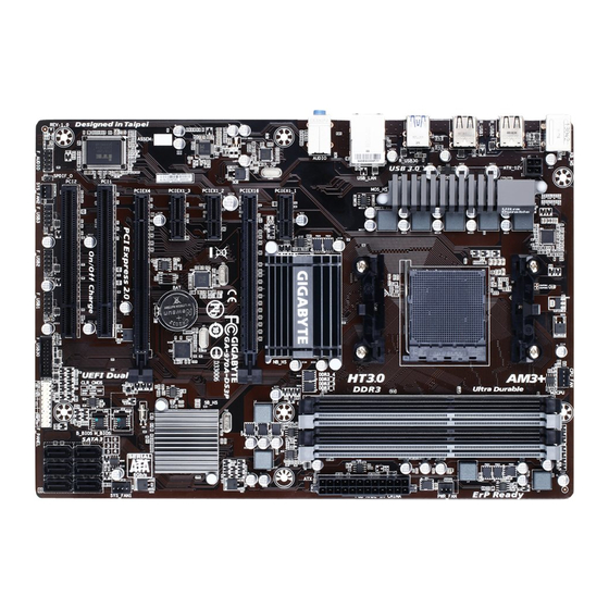
GA-970A-DS3P Motherboard Layout Socket AM3+ AUDIO AMD 970 Realtek ® GbE LAN PCIEX16 GA-970A-DS3P CODEC ® VL805 AMD SB950 PCIEX4 PCI1 PCI2 SATA3 0 2 4 1 3 5 For a longer expansion card, use other expansion slots. Box Contents…
-
Page 5: Ga-970A-Ds3P Motherboard Block Diagram
GA-970A-DS3P Motherboard Block Diagram AM3+/AM3 CPU 1 PCI Express x16 Dual Channel Memory Hyper Transport Bus PCIe CLK 4 USB 3.0/2.0 3 PCI Express x1 RJ45 Realtek ® VL805 ® GbE LAN PCIe CLK AMD 970 PCI Express Bus PCI Express Bus…
-
Page 6: Chapter 1 Hardware Installation
Chapter 1 Hardware Installation Installation Precautions The motherboard contains numerous delicate electronic circuits and components which can become manual and follow these procedures: Prior to installation, make sure the chassis is suitable for the motherboard. warranty sticker provided by your dealer. These stickers are required for warranty validation. Always remove the AC power by unplugging the power cord from the power outlet before installing or removing the motherboard or other hardware components.
-
Page 7
AM3+ Socket: AMD AM3+ FX processor AMD AM3 Phenom II processor/ AMD Athlon II processor ™ ™ Hyper Transport 4800 MT/s North Bridge: AMD 970 Chipset South Bridge: AMD SB950 Memory 4 x DDR3 DIMM sockets supporting up to 32 GB of system memory * Due to a Windows 32-bit operating system limitation, when more than 4 GB of physical the physical memory installed. -
Page 8
Internal 1 x front panel audio header Connectors 1 x S/PDIF Out header 1 x USB 3.0/2.0 header 3 x USB 2.0/1.1 headers Back Panel 1 x PS/2 keyboard port Connectors 1 x PS/2 mouse port 2 x USB 3.0/2.0 ports 6 x USB 2.0/1.1 ports 1 x RJ-45 port I/O Controller… -
Page 9: Installing The Cpu
Installing the CPU Read the following guidelines before you begin to install the CPU: Make sure that the motherboard supports the CPU. Always turn off the computer and unplug the power cord from the power outlet before installing the CPU to prevent hardware damage.
-
Page 10: Installing An Expansion Card
Installing an Expansion Card Read the following guidelines before you begin to install an expansion card: Make sure the motherboard supports the expansion card. Carefully read the manual that came with your expansion card. Always turn off the computer and unplug the power cord from the power outlet before installing an expansion card to prevent hardware damage.
-
Page 11: Internal Connectors
Internal Connectors ATX_12V F_PANEL CPU_FAN F_AUDIO SYS_FAN1/SYS_FAN2 SPDIF_O PWR_FAN F_USB30 SATA3 0/1/2/3/4/5 F_USB1/F_USB2/F_USB3 CLR_CMOS Read the following guidelines before connecting external devices: First make sure your devices are compliant with the connectors you wish to connect. Before installing the devices, be sure to turn off the devices and your computer. Unplug the power cord from the power outlet to prevent damage to the devices.
-
Page 12
1/2) ATX_12V/ATX (2×2 12V Power Connector and 2×12 Main Power Connector) With the use of the power connector, the power supply can supply enough stable power to all the components off and all devices are properly installed. The power connector possesses a foolproof design. Connect the power supply cable to the power connector in the correct orientation. -
Page 13
6) SATA3 0/1/2/3/4/5 (SATA 6Gb/s Connectors) The SATA connectors conform to SATA 6Gb/s standard and are compatible with SATA 3Gb/s and SATA 1.5Gb/s standard. Each SATA connector supports a single SATA device. The AMD SB950 controller supports RAID 0, RAID 1, RAID 5, RAID 10, and JBOD. Pin No. -
Page 14
9) F_PANEL (Front Panel Header) Connect the power switch, reset switch, speaker, chassis intrusion switch/sensor and system status indicator on the chassis to this header according to the pin assignments below. Note the positive and negative pins before connecting the cables. PLED/PWR Power/Sleep LED Power Switch… -
Page 15
11) SPDIF_O (S/PDIF Out Header) sound cards. For example, some graphics cards may require you to use a S/PDIF digital audio cable for digital audio output from your motherboard to your graphics card if you wish to connect an HDMI display to the graphics card and have digital audio output from the HDMI display at the same time. -
Page 16: Chapter 2 Bios Setup
To access the BIOS Setup program, press the <Delete> key during the POST when the power is turned on. To upgrade the BIOS, use either the GIGABYTE Q-Flash or @BIOS utility. Q-Flash allows the user to quickly and easily upgrade or back up BIOS without entering the operating system.
-
Page 17
M.I.T. This section provides information on the BIOS version, CPU base clock, CPU frequency, memory frequency, Whether the system will work stably with the overclock/overvoltage settings you made is dependent on your overall and reduce the useful life of these components. This page is for advanced users only and we recommend you not to M.I.T. -
Page 18
Advanced CPU Core Features CPU Clock Ratio, CPU Frequency The settings above are synchronous to those under the same items on the Advanced Frequency Settings menu. Core Performance Boost (Note 1) CPB Ratio (Note 1) CPU Unlock Cool&Quiet Disabled Disables this function. C1E Support Enables or disables the C1E CPU power-saving function in system halt state. -
Page 19
System Memory Multiplier Allows you to set the system memory multiplier. Auto sets memory multiplier according to memory SPD Memory Frequency (MHz) System Memory Multiplier settings. Advanced Memory Settings , System Memory Multiplier, Memory Frequency(MHz) (Note) The settings above are synchronous to those under the same items on the Advanced Frequency Settings menu. -
Page 20
Case Open Displays the detection status of the chassis intrusion detection device attached to the motherboard CI clear the chassis intrusion status record, set Reset Case Open Status to Enabled, save the settings to the CMOS, and then restart your system. CPU Vcore/Dram Voltage/+3.3V/+5V/+12V Displays the current system voltages. -
Page 21: System Information
System Information This section provides information on your motherboard model and BIOS version. You can also select the default language used by the BIOS and manually set the system time. System Language Selects the default language used by the BIOS. System Date value.
-
Page 22: Bios Features
System A password is required for booting the system and for entering the BIOS Setup program. Full Screen LOGO Show Allows you to determine whether to display the GIGABYTE Logo at system startup. Disabled skips the GIGABYTE Logo OS Type Allows you to select the operating system to be installed.
-
Page 23
CSM Support Never Disables UEFI CSM and supports UEFI BIOS boot process only. OS Type is set to Windows 8 or Windows 8 WHQL. Boot Mode Selection Allows you to select which type of operating system to boot. UEFI and Legacy Allows booting from operating systems that support legacy option ROM or UEFI option Legacy Only Allows booting from operating systems that only support legacy Option ROM. -
Page 24: Peripherals
Peripherals OnChip SATA Controller OnChip SATA Type controllers to AHCI mode. RAID Enables RAID for the SATA controller. OnChip SATA Port4/5 Type (SATA3 4/SATA3 5 connectors) mode of the integrated SATA3 4~SATA3 5 and eSATA connectors. As SATA Type The mode depends on the OnChip SATA Type settings. HD Audio Azalia Device If you wish to install a 3rd party add-in audio card instead of using the onboard audio, set this item to Disabled.
-
Page 25
Legacy USB Support XHCI Hand-off Determines whether to enable XHCI Hand-off feature for an operating system without XHCI Hand-off EHCI Hand-off Determines whether to enable EHCI Hand-off feature for an operating system without EHCI Hand-off Port 60/64 Emulation Enables or disables emulation of I/O ports 64h and 60h. This should be enabled for full legacy support for USB keyboards/mice in MS-DOS or in operating system that does not natively support USB devices. -
Page 26: Power Management
Power Management Resume by Alarm If enabled, set the date and time as following: Wake up hour/minute/second: Set the time at which the system will be powered on automatically. Note: When using this function, avoid inadequate shutdown from the operating system or removal of the AC power, or the settings may not be effective.
-
Page 27: Save & Exit
Power On Password Set the password when Power On By Keyboard is set to Password. Press <Enter> on this item and set a password with up to 5 characters and then press <Enter> to accept. To turn on the system, enter the password and press <Enter>. Note: To cancel the password, press <Enter>…
-
Page 28: Chapter 3 Appendix
Boot Override Allows you to select a device to boot immediately. Press <Enter> on the device you select and select Yes Select File in HDD/USB/FDD If your system becomes unstable and you have loaded the BIOS default settings, you can use this function Select File in HDD/USB/FDD automatically created by the BIOS, such as reverting the BIOS settings to the last settings that worked…
-
Page 29
This mode supports Windows 8.1/8 64-bit installation only. Steps: In BIOS Setup, go to BIOS Features and set OS Type to Windows 8 and CSM Support to Never. Save the changes and exit BIOS Setup. Running the UEFI RAID Utility as shown in Figure 3. -
Page 30
Creating a RAID Array 1. To create a new array, press <Enter> on the Create Array option. 2. The selection bar will move to the Disks section on the right of the screen. Select the hard drives to be included in the RAID array. -
Page 31: Drivers Installation
You can click the Install All button and «Xpress Install» will install all the recommended drivers. Or click Install Single Items to manually select the drivers you wish to install. For more software information, please visit GIGABYTE’s website. — 31 -…
-
Page 32: Regulatory Statements
This document must not be copied without our written permission, and the contents there of must not be imparted Contravention will be prosecuted. We believe that the information contained herein was accurate in all respects at the time of printing. GIGABYTE cannot, however, assume any responsibility for errors or omissions in this text. as a commitment by GIGABYTE.
-
Page 33
FCC Notice (U.S.A. Only) This equipment has been tested and found to comply with the limits for a Class B digital device, pursuant to Part 15 of the FCC Rules. These limits are designed to provide reasonable protection against harmful interference in a residential installation. -
Page 34
— 34 -… -
Page 35
— 35 -… -
Page 36: Contact Us
Address: No.6, Bao Chiang Road, Hsin-Tien Dist., New Taipei City 231,Taiwan TEL: +886-2-8912-4000, FAX: +886-2-8912-4005 You may go to the GIGABYTE website, select your language in the language list on the top right corner of the website. GIGABYTE eSupport http://esupport.gigabyte.com…
Посмотреть инструкция для Gigabyte GA-970A-DS3 бесплатно. Руководство относится к категории материнские платы, 1 человек(а) дали ему среднюю оценку 7.5. Руководство доступно на следующих языках: английский. У вас есть вопрос о Gigabyte GA-970A-DS3 или вам нужна помощь? Задайте свой вопрос здесь
Не можете найти ответ на свой вопрос в руководстве? Вы можете найти ответ на свой вопрос ниже, в разделе часто задаваемых вопросов о Gigabyte GA-970A-DS3.
Какие сертификаты Gigabyte GA-970A-DS3 имеет?
Какая ширина Gigabyte GA-970A-DS3?
Какая толщина Gigabyte GA-970A-DS3?
Инструкция Gigabyte GA-970A-DS3 доступно в русский?
Не нашли свой вопрос? Задайте свой вопрос здесь
-
Драйверы
25
-
Инструкции по эксплуатации
3
Языки:

Gigabyte GA-970A-DS3 инструкция по эксплуатации
(44 страницы)
- Языки:Английский
-
Тип:
PDF -
Размер:
15.77 MB
Просмотр

Gigabyte GA-970A-DS3 инструкция по эксплуатации
(44 страницы)
- Языки:Английский
-
Тип:
PDF -
Размер:
11.66 MB
Просмотр

Gigabyte GA-970A-DS3 инструкция по эксплуатации
(44 страницы)
- Языки:Китайский
-
Тип:
PDF -
Размер:
16.57 MB
Просмотр
На NoDevice можно скачать инструкцию по эксплуатации для Gigabyte GA-970A-DS3. Руководство пользователя необходимо для ознакомления с правилами установки и эксплуатации Gigabyte GA-970A-DS3. Инструкции по использованию помогут правильно настроить Gigabyte GA-970A-DS3, исправить ошибки и выявить неполадки.
GIGABYTE
GA-970A-DS3 (rev. 3.0) Инструкция по применению
Популярность:
989 просмотры
Подсчет страниц:
40 страницы
Тип файла:
Размер файла:
12.15 Mb