-
Драйверы
45
-
Инструкции по эксплуатации
26
Языки:

Gigabyte GA-H61M-DS2 инструкция по эксплуатации
(72 страницы)
- Языки:Венгерский, Греческий, Испанский, Итальянский, Немецкий, Польский, Португальский, Русский, Турецкий, Французский, Чешский
-
Тип:
PDF -
Размер:
18.6 MB -
Описание:
Installation Guidebook


На NoDevice можно скачать инструкцию по эксплуатации для Gigabyte GA-H61M-DS2. Руководство пользователя необходимо для ознакомления с правилами установки и эксплуатации Gigabyte GA-H61M-DS2. Инструкции по использованию помогут правильно настроить Gigabyte GA-H61M-DS2, исправить ошибки и выявить неполадки.
GIGABYTE
GA-H61M-DS2 (rev. 2.1) Инструкция по применению
Популярность:
2871 просмотры
Подсчет страниц:
40 страницы
Тип файла:
Размер файла:
12.15 Mb
Посмотреть инструкция для Gigabyte GA-H61M-DS2 бесплатно. Руководство относится к категории материнские платы, 3 человек(а) дали ему среднюю оценку 8.4. Руководство доступно на следующих языках: английский. У вас есть вопрос о Gigabyte GA-H61M-DS2 или вам нужна помощь? Задайте свой вопрос здесь
Не можете найти ответ на свой вопрос в руководстве? Вы можете найти ответ на свой вопрос ниже, в разделе часто задаваемых вопросов о Gigabyte GA-H61M-DS2.
Инструкция Gigabyte GA-H61M-DS2 доступно в русский?
Не нашли свой вопрос? Задайте свой вопрос здесь
![]()
GA-H61M-DS2
User’s Manual
Rev. 2002
12ME-H61MDS2-2002R

dr aobr eht o M
GA-H61M-DS2
Motherboard
GA-H61M-DS2
Dec. 4, 2011
Dec. 4, 2011
Copyright
© 2011 GIGA-BYTE TECHNOLOGY CO., LTD. All rights reserved.
The trademarks mentioned in this manual are legally registered to their respective owners.
Disclaimer
Information in this manual is protected by copyright laws and is the property of GIGABYTE.
Changes to the specifications and features in this manual may be made by GIGABYTE without prior notice. No part of this manual may be reproduced, copied, translated, transmitted, or published in any form or by any means without GIGABYTE’s prior written permission.
In order to assist in the use of this product, carefully read the User’s Manual.
For product-related information, check on our website at: http://www.gigabyte.com
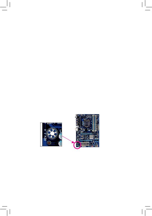
Identifying Your Motherboard Revision
The revision number on your motherboard looks like this: «REV: X.X.» For example, «REV: 1.0» means the revision of the motherboard is 1.0. Check your motherboard revision before updating motherboard BIOS, drivers, or when looking for technical information.
Example:

Table of Contents
|
GA-H61M-DS2 Motherboard Layout.…………………………………………………………………… |
5 |
|
|
GA-H61M-DS2 Motherboard Block Diagram.……………………………………………………….. |
6 |
|
|
Chapter 1 Hardware Installation………………………………………………………………………….. |
7 |
|
|
1-1 |
Installation Precautions………………………………………………………………………… |
7 |
|
1-2 |
Product Specifications………………………………………………………………………….. |
8 |
|
1-3 |
Installing the CPU………………………………………………………………………………. |
10 |
|
1-4 |
Installing the Memory………………………………………………………………………….. |
11 |
|
1-5 |
Installing an Expansion Card.………………………………………………………………. |
11 |
|
1-6 |
Back Panel Connectors………………………………………………………………………. |
12 |
|
1-7 |
Internal Connectors……………………………………………………………………………. |
13 |
|
Chapter 2 BIOS Setup……………………………………………………………………………………… |
20 |
|
|
2-1 |
Startup Screen.…………………………………………………………………………………. |
20 |
|
2-2 |
The Main Menu………………………………………………………………………………….. |
21 |
|
2-3 |
M.I.T…………………………………………………………………………………………………. |
22 |
|
2-4 |
System……………………………………………………………………………………………… |
29 |
|
2-5 |
BIOS Features…………………………………………………………………………………… |
30 |
|
2-6 |
Peripherals.………………………………………………………………………………………. |
32 |
|
2-7 |
Power Management.………………………………………………………………………….. |
33 |
|
2-8 |
Save & Exit……………………………………………………………………………………….. |
35 |
|
Chapter 3 Drivers Installation……………………………………………………………………………. |
36 |
|
|
Regulatory Statements…………………………………………………………………………………. |
37 |
— 4 —
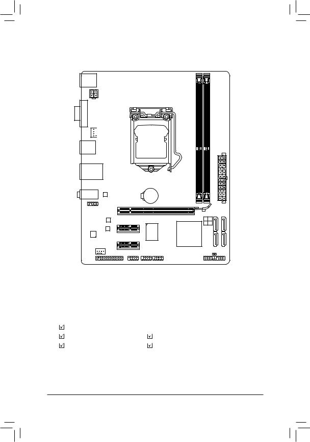
GA-H61M-DS2 Motherboard Layout
KB_MS
ATX_12V
VGA

 CPU_FAN
R_USB
USB_LAN
Atheros/
Realtek
GbE LAN
AUDIO
PCIEX16
F_AUDIO
M_BIOS PCIEX1_1 B_BIOS
LGA1155
ATX
BAT GA-H61M-DS2
SATA2
1 0
3 2
|
COMA |
F_USB1 |
CLR_CMOS |
|
LPT |
F_PANEL |
|
|
F_USB2 |
Box Contents
|
GA-H61M-DS2 motherboard |
|
|
Motherboard driver disk |
Two SATA cables |
|
User’s Manual |
I/O Shield |
The box contents above are for reference only and the actual items shall depend on the product package you obtain.
— 5 —
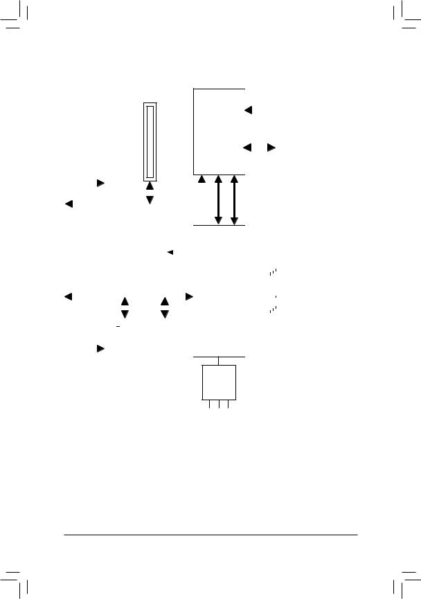
GA-H61M-DS2 Motherboard Block Diagram
1 PCI Express x16
PCIe CLK
(100 MHz)
|
x16 |
|||||||||||||||||||||||||
|
PCI Express Bus |
|||||||||||||||||||||||||
|
D-Sub |
|||||||||||||||||||||||||
|
PCI Express Bus |
|||||||||||||||||||||||||
|
x1 |
x1 |
||||||||||||||||||||||||
|
Atheros/ |
|||||||||||||||||||||||||
|
PCIe CLK |
Realtek |
||||||||||||||||||||||||
|
(100 MHz) |
GbE LAN |
||||||||||||||||||||||||
|
2 PCI Express x1 |
RJ45 |
||||||||||||||||||||||||
|
LAN |
|
CPU CLK+/- (100 MHz) |
||||||||
|
LGA1155 |
DDR3 1333/1066/800 MHz |
|||||||
|
CPU |
||||||||
|
Dual Channel Memory |
||||||||
Intel® H61
CODEC
Line In (Rear Speaker Out)
Line Out (Front Speaker Out)
MIC (Center/Subwoofer Speaker Out)
|
Dual BIOS |
|||||||||||||||
|
4 SATA 3Gb/s |
|||||||||||||||
|
8 USB 2.0/1.1 |
|||||||||||||||
|
LPC |
iTE |
LPT Port |
|||||||||||||
|
Bus |
|||||||||||||||
|
COM Port |
|||||||||||||||
|
IT8728 |
|||||||||||||||
|
PS/2 KB/Mouse |
— 6 —

Chapter 1 Hardware Installation
1-1 Installation Precautions
The motherboard contains numerous delicate electronic circuits and components which can become damaged as a result of electrostatic discharge (ESD). Prior to installation, carefully read the user’s manual and follow these procedures:
•• Prior to installation, make sure the chassis is suitable for the motherboard.
•• Prior to installation, do not remove or break motherboard S/N (Serial Number) sticker or warranty sticker provided by your dealer. These stickers are required for warranty validation.
•• Always remove the AC power by unplugging the power cord from the power outlet before installing or removing the motherboard or other hardware components.
•• When connecting hardware components to the internal connectors on the motherboard, make sure they are connected tightly and securely.
•• When handling the motherboard, avoid touching any metal leads or connectors.
•• It is best to wear an electrostatic discharge (ESD) wrist strap when handling electronic components such as a motherboard, CPU or memory. If you do not have an ESD wrist strap, keep your hands dry and first touch a metal object to eliminate static electricity.
•• Prior to installing the motherboard, please have it on top of an antistatic pad or within an electrostatic shielding container.
•• Before unplugging the power supply cable from the motherboard, make sure the power supply has been turned off.
•• Before turning on the power, make sure the power supply voltage has been set according to the local voltage standard.
•• Before using the product, please verify that all cables and power connectors of your hardware components are connected.
•• To prevent damage to the motherboard, do not allow screws to come in contact with the motherboard circuit or its components.
•• Make sure there are no leftover screws or metal components placed on the motherboard or within the computer casing.
•• Do not place the computer system on an uneven surface.
•• Do not place the computer system in a high-temperature environment.
•• Turning on the computer power during the installation process can lead to damage to system components as well as physical harm to the user.
•• If you are uncertain about any installation steps or have a problem related to the use of the product, please consult a certified computer technician.
— 7 —
|
1-2 |
Product Specifications |
|||
|
CPU |
Support for Intel® Core™ i7 processors/Intel® Core™ i5 processors/ |
|||
|
Intel® Core™ i3 processors/Intel® Pentium® processors/Intel® Celeron® processors |
||||
|
in the LGA1155 package |
||||
|
(Go to GIGABYTE’s website for the latest CPU support list.) |
||||
|
L3 cache varies with CPU |
||||
|
Chipset |
Intel® H61 Express Chipset |
|||
|
Memory |
2 x 1.5V DDR3 DIMM sockets supporting up to 16 GB of system memory |
|||
|
* Due to Windows 32-bit operating system limitation, when more than 4 GB of physical |
||||
|
memory is installed, the actual memory size displayed will be less than 4 GB. |
||||
|
Dual channel memory architecture |
||||
|
Support for DDR3 1333/1066/800 MHz memory modules |
||||
|
Support for non-ECC memory modules |
||||
|
(Go to GIGABYTE’s website for the latest supported memory speeds and memory |
||||
|
modules.) |
||||
|
Onboard |
Integrated Graphics Processor: |
|||
|
Graphics |
— |
1 x D-Sub port |
||
|
Audio |
Realtek/VIA HD audio codec |
|||
|
High Definition Audio |
||||
|
2/4/5.1/7.1-channel |
*Toconfigure 7.1-channel audio, you have to use an HD front panel audio module and enable the multi-channel audio feature through the audio driver.
|
LAN |
1 x Atheros/Realtek GbE LAN chip (10/100/1000 Mbit) |
|
|
Expansion Slots |
1 x PCI Express x16 slot, running at x16 |
|
|
2 x PCI Express x1 slots |
||
|
(All PCI Express slots conform to PCI Express 2.0 standard.) |
||
|
Storage Interface |
Chipset: |
|
|
— 4 x SATA 3Gb/s connectors supporting up to 4 SATA 3Gb/s devices |
||
|
USB |
Chipset: |
|
|
— Up to 8 USB 2.0/1.1 ports (4 ports on the back panel, 4 ports available through |
||
|
the internal USB headers) |
||
|
Internal |
1 x 24-pin ATX main power connector |
|
|
Connectors |
1 x 4-pin ATX 12V power connector |
|
|
4 x SATA 3Gb/s connectors |
||
|
1 x CPU fan header |
||
|
1 x system fan header |
||
|
1 x front panel header |
||
|
1 x front panel audio header |
||
|
2 x USB 2.0/1.1 headers |
||
|
1 x parallel port header |
||
|
1 x serial port header |
||
|
1 x Clear CMOS jumper |
— 8 —
|
Back Panel |
1 x PS/2 keyboard port |
|
|
Connectors |
1 x PS/2 mouse port |
|
|
1 x D-Sub port |
||
|
4 x USB 2.0/1.1 ports |
||
|
1 x RJ-45 port |
||
|
3 x audio jacks (Line In/Line Out/Microphone) |
||
|
I/O Controller |
iTE IT8728 chip |
|
|
Hardware |
System voltage detection |
|
|
Monitor |
CPU/System temperature detection |
|
CPU/System fan speed detection |
||
|
CPU/System fan speed control |
||
|
* Whether the CPU/System fan speed control function is supported will depend on |
||
|
the CPU/System cooler you install. |
||
|
BIOS |
2 x 32 Mbit flash |
|
|
Use of licensed AMI EFI BIOS |
||
|
Support for DualBIOS™ |
||
|
PnP 1.0a, DMI 2.0, SM BIOS 2.6, ACPI 2.0a |
||
|
Bundled |
Norton Internet Security (OEM version) |
|
|
Software |
||
|
Operating |
Support for Microsoft® Windows 7/Vista/XP |
|
|
System |
||
|
Form Factor |
Micro ATX Form Factor; 22.6cm x 17.4cm |
* GIGABYTE reserves the right to make any changes to the product specifications and product-related information without prior notice.
— 9 —
|
1-3 |
Installing the CPU |
|
|
Read the following guidelines before you begin to install the CPU: |
||
|
•• |
Make sure that the motherboard supports the CPU. |
|
|
(Go to GIGABYTE’s website for the latest CPU support list.) |
||
|
•• |
Always turn off the computer and unplug the power cord from the power outlet before installing |
|
|
the CPU to prevent hardware damage. |
||
|
•• |
Locate the pin one of the CPU. The CPU cannot be inserted if oriented incorrectly. (Or you may |
|
|
locate the notches on both sides of the CPU and alignment keys on the CPU socket.) |
||
|
•• |
Apply an even and thin layer of thermal grease on the surface of the CPU. |
|
|
•• |
Do not turn on the computer if the CPU cooler is not installed, otherwise overheating and dam- |
|
|
age of the CPU may occur. |
||
|
•• |
Set the CPU host frequency in accordance with the CPU specifications. It is not recommended |
|
|
that the system bus frequency be set beyond hardware specifications since it does not meet the |
||
|
standard requirements for the peripherals. If you wish to set the frequency beyond the standard |
||
|
specifications, please do so according to your hardware specifications including the CPU, graph- |
||
|
ics card, memory, hard drive, etc. |
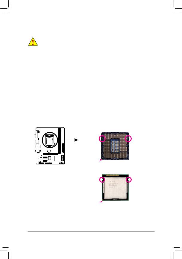
Installing the CPU
A. Locate the alignment keys on the motherboard CPU socket and the notches on the CPU.
LGA1155 CPU Socket
|
Alignment Key |
Alignment Key |
Pin One Corner of the CPU Socket
LGA1155 CPU
Triangle Pin One Marking on the CPU
— 10 —
![]()
1-4 Installing the Memory
Read the following guidelines before you begin to install the memory:
•• Make sure that the motherboard supports the memory. It is recommended that memory of the same capacity, brand, speed, and chips be used.
(Go to GIGABYTE’s website for the latest supported memory speeds and memory modules.)
•• Always turn off the computer and unplug the power cord from the power outlet before installing the memory to prevent hardware damage.
•• Memory modules have a foolproof design. A memory module can be installed in only one direction. If you are unable to insert the memory, switch the direction.
Dual Channel Memory Configuration
This motherboard provides two DDR3 memory sockets and supports Dual Channel Technology. After the memory is installed, the BIOS will automatically detect the specifications and capacity of the memory. Enabling Dual Channel memory mode will double the original memory bandwidth.
The two DDR3 memory sockets are divided into two channels and each channel has one memory socket as following:
 Channel A: DDR3_1
  Channel B: DDR3_2
DDR3_2
DDR3_1
Due to CPU limitations, read the following guidelines before installing the memory in Dual Channel mode. 111 Dual Channel mode cannot be enabled if only one DDR3 memory module is installed.
222When enabling Dual Channel mode with two memory modules, it is recommended that memory of the same capacity, brand, speed, and chips be used for optimum performance.
1-5 Installing an Expansion Card
Read the following guidelines before you begin to install an expansion card:
•• Make sure the motherboard supports the expansion card. Carefully read the manual that came with your expansion card.
•• Always turn off the computer and unplug the power cord from the power outlet before installing an expansion card to prevent hardware damage.
— 11 —
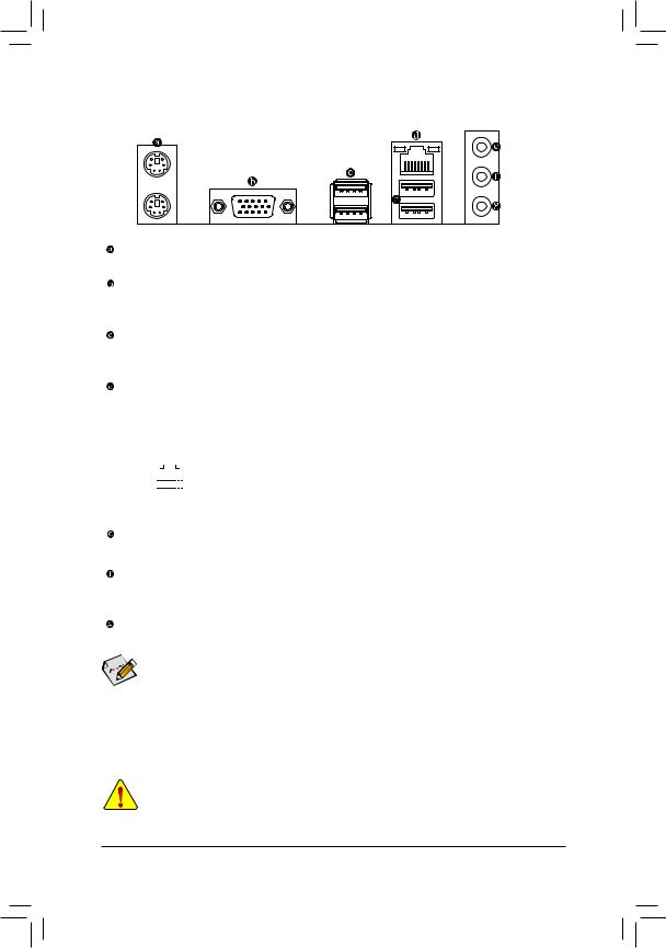
1-6 Back Panel Connectors
PS/2 Keyboard and PS/2 Mouse Port
Use the upper port (green) to connect a PS/2 mouse and the lower port (purple) to connect a PS/2 keyboard.
D-Sub Port
The D-Sub port supports a 15-pin D-Sub connector. Connect a monitor that supports D-Sub connection to this port.
USB 2.0/1.1 Port
The USB port supports the USB 2.0/1.1 specification. Use this port for USB devices such as a USB keyboard/mouse, USB printer, USB flash drive and etc.
RJ-45 LAN Port
The Gigabit Ethernet LAN port provides Internet connection at up to 1 Gbps data rate. The following describes the states of the LAN port LEDs.
|
Connection/ |
Activity LED |
Connection/Speed LED: |
Activity LED: |
||||||||||||||||
|
Speed LED |
|||||||||||||||||||
|
State |
Description |
State |
Description |
||||||||||||||||
|
Orange |
1 Gbps data rate |
Blinking |
Data transmission or receiving is occurring |
||||||||||||||||
|
Green |
100 Mbps data rate |
Off |
No data transmission or receiving is occurring |
||||||||||||||||
|
LAN Port |
Off |
10 Mbps data rate |
|||||||||||||||||
Line In Jack (Blue)
The default line in jack. Use this audio jack for line in devices such as an optical drive, walkman, etc.
Line Out Jack (Green)
The default line out jack. Use this audio jack for a headphone or 2-channel speaker. This jack can be used to connect front speakers in a 4/5.1/7.1-channel audio configuration.
Mic In Jack (Pink)
The default Mic in jack. Microphones must be connected to this jack.

 To configure 7.1-channel audio, you have to use an HD front panel audio module and enable the multi-channel audio feature through the audio driver.
•• When removing the cable connected to a back panel connector, first remove the cable from your device and then remove it from the motherboard.
•• When removing the cable, pull it straight out from the connector. Do not rock it side to side to prevent an electrical short inside the cable connector.
— 12 —
 Loading…
View a manual of the Gigabyte GA-H61M-DS2 below. All manuals on ManualsCat.com can be viewed completely free of charge. By using the ‘Select a language’ button, you can choose the language of the manual you want to view.
Page: 1
GA-H61M-DS2
User’s Manual
Rev. 1201
Page: 2
Motherboard
GA-H61M-DS2
Sept.
16,
2011
Sept.
16,
2011
Motherboard
GA-H61M-DS2
Page: 3
Copyright
© 2011 GIGA-BYTE TECHNOLOGY CO., LTD. All rights reserved.
The trademarks mentioned in this manual are legally registered to their respective owners.
Disclaimer
Information in this manual is protected by copyright laws and is the property of GIGABYTE.
Changes to the specifications and features in this manual may be made by GIGABYTE without
prior notice. No part of this manual may be reproduced, copied, translated, transmitted, or
published in any form or by any means without GIGABYTE’s prior written permission.
In order to assist in the use of this product, carefully read the User’s Manual.
For product-related information, check on our website at: http://www.gigabyte.com
Identifying Your Motherboard Revision
The revision number on your motherboard looks like this: «REV: X.X.» For example, «REV: 1.0»
means the revision of the motherboard is 1.0. Check your motherboard revision before updating
motherboard BIOS, drivers, or when looking for technical information.
Example:
Page: 4
— 4 —
Table of Contents
GA-H61M-DS2 Motherboard Layout.
…………………………………………………………………….5
GA-H61M-DS2 Motherboard Block Diagram………………………………………………………….6
Chapter 1 Hardware Installation…………………………………………………………………………..7
1-1 Installation Precautions………………………………………………………………………… 7
1-2 Product Specifications………………………………………………………………………….. 8
1-3 Installing the CPU………………………………………………………………………………. 10
1-4 Installing the Memory…………………………………………………………………………..11
1-5 Installing an Expansion Card…………………………………………………………………11
1-6 Back Panel Connectors………………………………………………………………………. 12
1-7 Internal Connectors……………………………………………………………………………. 13
Chapter 2 BIOS Setup………………………………………………………………………………………20
2-1 Startup Screen.
…………………………………………………………………………………..20
2-2 The Main Menu………………………………………………………………………………….. 21
2-3 MB Intelligent Tweaker(M.I.T.)………………………………………………………………22
2-4 Standard CMOS Features…………………………………………………………………… 28
2-5 Advanced BIOS Features…………………………………………………………………….29
2-6 Integrated Peripherals………………………………………………………………………… 31
2-7 Power Management Setup………………………………………………………………….. 32
2-8 PC Health Status………………………………………………………………………………..34
2-9 Load Fail-Safe Defaults……………………………………………………………………….35
2-10 Load Optimized Defaults……………………………………………………………………..36
2-11 Set Supervisor/User Password…………………………………………………………….36
2-12 Save & Exit Setup………………………………………………………………………………. 37
2-13 Exit Without Saving……………………………………………………………………………. 37
Chapter 3 Drivers Installation…………………………………………………………………………….38
Regulatory Statements………………………………………………………………………………….39
Page: 5
— 5 —
GA-H61M-DS2 Motherboard Layout
Box Contents
GA-H61M-DS2 motherboard
Motherboard driver disk Two SATA cables
User’s Manual I/O Shield
The box contents above are for reference only and the actual items shall depend on the product package you obtain.
KB_MS
CPU_FAN
LGA1155
ATX
GA-H61M-DS2
F_AUDIO
AUDIO
B_BIOS
DDR3_1
DDR3_2
BAT
F_PANEL
ATX_12V
Intel®
H61
SATA2_0
SATA2_1
SATA2_2
SATA2_3
R_USB
CODEC
CLR_CMOS
M_BIOS
VGA
USB_LAN
PCIEX16
PCIEX1_1
F_USB1
F_USB2
LPT
COMA
SYS_FAN
Atheros/
Realtek
GbE LAN
iTE
IT8728
PCIEX1_2
Page: 6
— 6 —
GA-H61M-DS2 Motherboard Block Diagram
PS/2 KB/Mouse
LGA1155
CPU
Intel®
H61
PCIe CLK
(100 MHz)
PCI Express Bus
CPU CLK+/- (100 MHz)
1 PCI Express x16
Dual BIOS
COM Port
LPT
8 USB 2.0/1.1
LPC
Bus
DDR3 1333/1066/800 MHz
PCI Express Bus
PCIe CLK
(100 MHz) iTE
IT8728
2 PCI Express x1
4 SATA 3Gb/s
D-Sub
DMI
2.0
FDI
x16
Dual Channel Memory
x1 x1
Line
Out
(Front
Speaker
Out)
MIC
(Center/Subwoofer
Speaker
Out)
Line
In
(Rear
Speaker
Out)
CODEC
LAN
RJ45
Atheros/
Realtek
GbE LAN
Page: 7
— 7 —
1-1 Installation Precautions
The motherboard contains numerous delicate electronic circuits and components which can
become damaged as a result of electrostatic discharge (ESD). Prior to installation, carefully read
the user’s manual and follow these procedures:
Prior to installation, make sure the chassis is suitable for the motherboard.
•
•
Prior to installation, do not remove or break motherboard S/N (Serial Number) sticker or
•
•
warranty sticker provided by your dealer. These stickers are required for warranty validation.
Always remove the AC power by unplugging the power cord from the power outlet before
•
•
installing or removing the motherboard or other hardware components.
When connecting hardware components to the internal connectors on the motherboard,
•
•
make sure they are connected tightly and securely.
When handling the motherboard, avoid touching any metal leads or connectors.
•
•
It is best to wear an electrostatic discharge (ESD) wrist strap when handling electronic com-
•
•
ponents such as a motherboard, CPU or memory. If you do not have an ESD wrist strap,
keep your hands dry and first touch a metal object to eliminate static electricity.
Prior to installing the motherboard, please have it on top of an antistatic pad or within an
•
•
electrostatic shielding container.
Before unplugging the power supply cable from the motherboard, make sure the power sup-
•
•
ply has been turned off.
Before turning on the power, make sure the power supply voltage has been set according to
•
•
the local voltage standard.
Before using the product, please verify that all cables and power connectors of your hard-
•
•
ware components are connected.
To prevent damage to the motherboard, do not allow screws to come in contact with the
•
•
motherboard circuit or its components.
Make sure there are no leftover screws or metal components placed on the motherboard or
•
•
within the computer casing.
Do not place the computer system on an uneven surface
•
• .
Do not place the computer system in a high-temperature environment.
•
•
Turning on the computer power during the installation process can lead to damage to sys-
•
•
tem components as well as physical harm to the user.
If you are uncertain about any installation steps or have a problem related to the use of the
•
•
product, please consult a certified computer technician.
Chapter 1 Hardware Installation
Page: 8
— 8 —
1-2 Product Specifications
CPU Support for Intel
® Core™ i7 processors/Intel® Core™ i5 processors/
Intel® Core™ i3 processors/Intel® Pentium® processors/Intel® Celeron® processors
in the LGA1155 package
(Go to GIGABYTE’s website for the latest CPU support list.)
L3 cache varies with CPU
Chipset Intel
® H61 Express Chipset
Memory 2 x 1.5V DDR3 DIMM sockets supporting up to 16 GB of system memory
*
Due to Windows 32-bit operating system limitation, when more than 4 GB of physical
memory is installed, the actual memory size displayed will be less than 4 GB.
Dual channel memory architecture
Support for DDR3 1333/1066/800 MHz memory modules
Support for non-ECC memory modules
(Go to GIGABYTE’s website for the latest supported memory speeds and memory
modules.)
Onboard
Graphics
Integrated Graphics Processor:
— 1 x D-Sub port
Audio Realtek/VIA HD audio codec
High Definition Audio
2/4/5.1/7.1-channel
*
To configure 7.1-channel audio, you have to use an HD front panel audio module and
enable the multi-channel audio feature through the audio driver.
LAN 1 x Atheros/Realtek GbE LAN chip (10/100/1000 Mbit)
Expansion Slots 1 x PCI Express x16 slot, running at x16
2 x PCI Express x1 slots
(All PCI Express slots conform to PCI Express 2.0 standard.)
Storage Interface Chipset:
— 4 x SATA 3Gb/s connectors supporting up to 4 SATA 3Gb/s devices
USB Chipset:
—
Up to 8 USB 2.0/1.1 ports (4 ports on the back panel, 4 ports available through
the internal USB headers)
Internal
Connectors
1 x 24-pin ATX main power connector
1 x 4-pin ATX 12V power connector
4 x SATA 3Gb/s connectors
1 x CPU fan header
1 x system fan header
1 x front panel header
1 x front panel audio header
2 x USB 2.0/1.1 headers
1 x parallel port header
1 x serial port header
1 x Clear CMOS jumper
Page: 9
— 9 —
Back Panel
Connectors
1 x PS/2 keyboard port
1 x PS/2 mouse port
1 x D-Sub port
4 x USB 2.0/1.1 ports
1 x RJ-45 port
3 x audio jacks (Line In/Line Out/Microphone)
I/O Controller iTE IT8728 chip
Hardware
Monitor
System voltage detection
CPU/System temperature detection
CPU/System fan speed detection
CPU overheating warning
CPU/System fan fail warning
CPU/System fan speed control
*
Whether the CPU/System fan speed control function is supported will depend on
the CPU/System cooler you install.
BIOS 2 x 32 Mbit flash
Use of licensed AWARD BIOS
Support for DualBIOS
™
PnP 1.0a, DMI 2.0, SM BIOS 2.4, ACPI 1.0b
Unique Features Support for @BIOS
Support for Q-Flash
Support for Xpress BIOS Rescue
Support for Download Center
Support for Xpress Install
Support for Xpress Recovery2
Support for EasyTune
* Available functions in EasyTune may differ by motherboard model.
Support for Smart 6
™
Support for Auto Green
Support for ON/OFF Charge
Support for Cloud OC
Support for 3TB+ Unlock
Support for TouchBIOS
Support for Q-Share
Bundled
Software
Norton Internet Security (OEM version)
Operating
System
Support for Microsoft
® Windows 7/Vista/XP
Form Factor Micro ATX Form Factor; 22.6cm x 17.4cm
* GIGABYTE reserves the right to make any changes to the product specifications and product-related information
without prior notice.
Page: 10
— 10 —
1-3 Installing the CPU
Installing the CPU
A. Locate the alignment keys on the motherboard CPU socket and the notches on the CPU.
Alignment Key
Alignment Key
LGA1155 CPU Socket
Pin One Corner of the CPU Socket
Notch
Notch
LGA1155 CPU
Triangle Pin One Marking on the CPU
Read the following guidelines before you begin to install the CPU:
Make sure that the motherboard supports the CPU.
•
•
(Go to GIGABYTE’s website for the latest CPU support list.)
Always turn off the computer and unplug the power cord from the power outlet before installing
•
•
the CPU to prevent hardware damage.
Locate the pin one of the CPU. The CPU cannot be inserted if oriented incorrectly. (Or you may
•
•
locate the notches on both sides of the CPU and alignment keys on the CPU socket.)
Apply an even and thin layer of thermal grease on the surface of the CPU.
•
•
Do not turn on the computer if the CPU cooler is not installed, otherwise overheating and dam-
•
•
age of the CPU may occur.
Set the CPU host frequency in accordance with the CPU specifications. It is not recommended
•
•
that the system bus frequency be set beyond hardware specifications since it does not meet the
standard requirements for the peripherals. If you wish to set the frequency beyond the standard
specifications, please do so according to your hardware specifications including the CPU, graph-
ics card, memory, hard drive, etc.
Page: 11
— 11 —
1-4 Installing the Memory
Due to CPU limitations, read the following guidelines before installing the memory in Dual Channel mode.
Dual Channel mode cannot be enabled if only one DDR3 memory module is installed.
111
When enabling Dual Channel mode with two memory modules, it is recommended that memory of
222
the same capacity, brand, speed, and chips be used for optimum performance.
Dual Channel Memory Configuration
This motherboard provides two DDR3 memory sockets and supports Dual Channel Technology. After the
memory is installed, the BIOS will automatically detect the specifications and capacity of the memory. En-
abling Dual Channel memory mode will double the original memory bandwidth.
The two DDR3 memory sockets are divided into two channels and each channel has one memory socket as
following:
Channel A: DDR3_1
Channel B: DDR3_2
Read the following guidelines before you begin to install the memory:
Make sure that the motherboard supports the memory. It is recommended that memory of the
•
•
same capacity, brand, speed, and chips be used.
(Go to GIGABYTE’s website for the latest supported memory speeds and memory modules.)
Always turn off the computer and unplug the power cord from the power outlet before installing
•
•
the memory to prevent hardware damage.
Memory modules have a foolproof design. A memory module can be installed in only one direc-
•
•
tion. If you are unable to insert the memory, switch the direction.
DDR3_1
DDR3_2
1-5 Installing an Expansion Card
Read the following guidelines before you begin to install an expansion card:
Make sure the motherboard supports the expansion card. Carefully read the manual that came
•
•
with your expansion card.
Always turn off the computer and unplug the power cord from the power outlet before installing
•
•
an expansion card to prevent hardware damage.
Page: 12
— 12 —
1-6 Back Panel Connectors
PS/2 Keyboard and PS/2 Mouse Port
Use the upper port (green) to connect a PS/2 mouse and the lower port (purple) to connect a PS/2 keyboard.
D-Sub Port
The D-Sub port supports a 15-pin D-Sub connector. Connect a monitor that supports D-Sub connection
to this port.
USB 2.0/1.1 Port
The USB port supports the USB 2.0/1.1 specification. Use this port for USB devices such as a USB key-
board/mouse, USB printer, USB flash drive and etc.
RJ-45 LAN Port
The Gigabit Ethernet LAN port provides Internet connection at up to 1 Gbps data rate. The following
describes the states of the LAN port LEDs.
Activity LED
Connection/
Speed LED
LAN Port
Activity LED:
Connection/Speed LED:
State Description
Orange 1 Gbps data rate
Green 100 Mbps data rate
Off 10 Mbps data rate
State Description
Blinking Data transmission or receiving is occurring
Off No data transmission or receiving is occurring
When removing the cable connected to a back panel connector, first remove the cable from your
•
•
device and then remove it from the motherboard.
When removing the cable, pull it straight out from the connector. Do not rock it side to side to
•
•
prevent an electrical short inside the cable connector.
Line In Jack (Blue)
The default line in jack. Use this audio jack for line in devices such as an optical drive, walkman, etc.
Line Out Jack (Green)
The default line out jack. Use this audio jack for a headphone or 2-channel speaker. This jack can be
used to connect front speakers in a 4/5.1/7.1-channel audio configuration.
Mic In Jack (Pink)
The default Mic in jack. Microphones must be connected to this jack.
To configure 7.1-channel audio, you have to use an HD front panel audio module and enable the
multi-channel audio feature through the audio driver.
Page: 13
— 13 —
1-7 Internal Connectors
Read the following guidelines before connecting external devices:
First make sure your devices are compliant with the connectors you wish to connect.
•
•
Before installing the devices, be sure to turn off the devices and your computer. Unplug the
•
•
power cord from the power outlet to prevent damage to the devices.
After installing the device and before turning on the computer, make sure the device cable has
•
•
been securely attached to the connector on the motherboard.
1) ATX_12V
2) ATX
3) CPU_FAN
4) SYS_FAN
5) SATA2_0/1/2/3
6) F_PANEL
7) F_AUDIO
 F_USB1/2
9) COMA
10) LPT
11) CLR_CMOS
12) BAT
2
5
9
10
7
4
8 6
3
1
12
11
Page: 14
— 14 —
13
1
24
12
ATX
ATX:
1/2) ATX_12V/ATX (2×2 12V Power Connector and 2×12 Main Power Connector)
With the use of the power connector, the power supply can supply enough stable power to all the com-
ponents on the motherboard. Before connecting the power connector, first make sure the power supply
is turned off and all devices are properly installed. The power connector possesses a foolproof design.
Connect the power supply cable to the power connector in the correct orientation. The 12V power con-
nector mainly supplies power to the CPU. If the 12V power connector is not connected, the computer will
not start.
To meet expansion requirements, it is recommended that a power supply that can withstand high
power consumption be used (500W or greater). If a power supply is used that does not provide
the required power, the result can lead to an unstable or unbootable system.
ATX_12V:
Pin No. Definition
1 GND
2 GND
3 +12V
4 +12V
Pin No. Definition Pin No. Definition
1 3.3V 13 3.3V
2 3.3V 14 -12V
3 GND 15 GND
4 +5V 16 PS_ON (soft On/Off)
5 GND 17 GND
6 +5V 18 GND
7 GND 19 GND
8 Power Good 20 -5V
9 5VSB (stand by +5V) 21 +5V
10 +12V 22 +5V
11 +12V (Only for 2×12-pinATX) 23 +5V (Only for 2×12-pin ATX)
12 3.3V (Only for 2×12-pinATX) 24 GND (Only for 2×12-pin ATX)
ATX_12V
1
3
2
4
Page: 15
— 15 —
3/4) CPU_FAN/SYS_FAN (Fan Headers)
The motherboard has a 4-pin CPU fan header (CPU_FAN) and a 4-pin system fan header (SYS_FAN).
Most fan headers possess a foolproof insertion design. When connecting a fan cable, be sure to connect
it in the correct orientation (the black connector wire is the ground wire). The motherboard supports CPU
fan speed control, which requires the use of a CPU fan with fan speed control design. For optimum heat
dissipation, it is recommended that a system fan be installed inside the chassis.
Be sure to connect fan cables to the fan headers to prevent your CPU and system from overheating. Over-
•
•
heating may result in damage to the CPU or the system may hang.
These fan headers are not configuration jumper blocks. Do not place a jumper cap on the headers.
•
•
CPU_FAN/SYS_FAN:
Pin No. Definition
1 GND
2 +12V
3 Sense
4 Speed Control
5) SATA2_0/1/2/3 (SATA 3Gb/s Connectors)
The SATA connectors conform to SATA 3Gb/s standard and are compatible with SATA 1.5Gb/s standard.
Each SATA connector supports a single SATA device.
Please connect the L-shaped end of
the SATA cable to your SATA hard
drive.
Pin No. Definition
1 GND
2 TXP
3 TXN
4 GND
5 RXN
6 RXP
7 GND
SATA2_2
SATA2_3
SATA2_0
SATA2_1
7
1
7
1
DEBUG
PORT
DEBUG
PORT
DEBUG
PORT
DEBUG
PORT
CPU_FAN
SYS_FAN
1
1
Page: 16
— 16 —
6) F_PANEL (Front Panel Header)
Connect the power switch, reset switch, speaker, and system status indicator on the chassis to this
header according to the pin assignments below. Note the positive and negative pins before connecting
the cables.
The front panel design may differ by chassis. A front panel module mainly consists of power
switch, reset switch, power LED, hard drive activity LED, speaker and etc. When connecting your
chassis front panel module to this header, make sure the wire assignments and the pin assign-
ments are matched correctly.
1
2
19
20
MSG-
PW-
SPEAK+
SPEAK-
MSG+
PW+
Message/Power/
Sleep LED
HD-
RES+
HD+
RES-
Hard Drive
Activity LED
Reset
Switch
Speaker
F_AUDIO(H)
DB_PORT
F_PANEL(NH) F_PANEL
(H61M-D2)
ACPI_CPT
(GA-IVB)
SMB_CPT
(GA-IVB)
CLR_CMOS
CI
DIS_ME
GP15_CPT
(GA-IVB)
XDP_CPU
XDP_PCH
(GA-IVB)
Voltage measurement module(X58A-OC)
PCIe power connector (SATA)(X58A-OC)
DIP
1
2
3
DIP
1
2
3
DIP
1
2
3
DIP
1 2 3
1
1
1
1
BIOS Switcher (X58A-OC)
PWM Switch (X58A-OC)
M_SATA
Power
Switch
Power LED
CI-
CI+
PWR-
PWR+
Chassis Intrusion
Header
PW
•
• (Power Switch):
Connects to the power switch on the chassis front panel. You may configure the way to turn off your
system using the power switch (refer to Chapter 2, «BIOS Setup,» «Power Management Setup,» for
more information).
SPEAK
•
• (Speaker):
Connects to the speaker on the chassis front panel. The system reports system startup status by is-
suing a beep code. One single short beep will be heard if no problem is detected at system startup. If
a problem is detected, the BIOS may issue beeps in different patterns to indicate the problem.
HD
•
• (Hard Drive Activity LED):
Connects to the hard drive activity LED on the chassis front panel. The LED is on when the hard drive
is reading or writing data.
RES
•
• (Reset Switch):
Connects to the reset switch on the chassis front panel. Press the reset switch to restart the computer
if the computer freezes and fails to perform a normal restart.
CI
•
• (Chassis Intrusion Header):
Connects to the chassis intrusion switch/sensor on the chassis that can detect if the chassis cover
has been removed. This function requires a chassis with a chassis intrusion switch/sensor.
MSG/PWR
•
• (Message/Power/Sleep LED):
System Status LED
S0 On
S1 Blinking
S3/S4/S5 Off
Connects to the power status indicator on the chassis front panel. The LED
is on when the system is operating. The LED keeps blinking when the sys-
tem is in S1 sleep state. The LED is off when the system is in S3/S4 sleep
state or powered off (S5).
Page: 17
— 17 —
7) F_AUDIO (Front Panel Audio Header)
The front panel audio header supports Intel High Definition audio (HD) and AC’97 audio. You may connect
your chassis front panel audio module to this header. Make sure the wire assignments of the module con-
nector match the pin assignments of the motherboard header. Incorrect connection between the module
connector and the motherboard header will make the device unable to work or even damage it.
The front panel audio header supports HD audio by default.
•
•
Audio signals will be present on both of the front and back panel audio connections simultane-
•
•
ously.
Some chassis provide a front panel audio module that has separated connectors on each wire
•
•
instead of a single plug. For information about connecting the front panel audio module that
has different wire assignments, please contact the chassis manufacturer.
For HD Front Panel Audio: ForAC’97 Front PanelAudio:
Pin No. Definition
1 MIC2_L
2 GND
3 MIC2_R
4 -ACZ_DET
5 LINE2_R
6 GND
7 FAUDIO_JD
8 No Pin
9 LINE2_L
10 GND
Pin No. Definition
1 MIC
2 GND
3 MIC Power
4 NC
5 Line Out (R)
6 NC
7 NC
8 No Pin
9 Line Out (L)
10 NC
1
2
9
10
F_USB1/2 (USB 2.0/1.1 Headers)
The headers conform to USB 2.0/1.1 specification. Each USB header can provide two USB ports via an
optional USB bracket. For purchasing the optional USB bracket, please contact the local dealer.
Do not plug the IEEE 1394 bracket (2×5-pin) cable into the USB header.
•
•
Prior to installing the USB bracket, be sure to turn off your computer and unplug the power
•
•
cord from the power outlet to prevent damage to the USB bracket.
Pin No. Definition
1 Power (5V)
2 Power (5V)
3 USB DX-
4 USB DY-
5 USB DX+
6 USB DY+
7 GND
8 GND
9 No Pin
10 NC
10
9
2
1
Page: 18
— 18 —
Pin No. Definition
1 NDCD-
2 NSIN
3 NSOUT
4 NDTR-
5 GND
6 NDSR-
7 NRTS-
8 NCTS-
9 NRI-
10 No Pin
9) COMA (Serial Port Header)
The COM header can provide one serial port via an optional COM port cable. For purchasing the op-
tional COM port cable, please contact the local dealer.
10) LPT (Parallel Port Header)
The LPT header can provide one parallel port via an optional LPT port cable. For purchasing the optional
LPT port cable, please contact the local dealer.
Pin No. Definition Pin No. Definition
1 STB- 14 GND
2 AFD- 15 PD6
3 PD0 16 GND
4 ERR- 17 PD7
5 PD1 18 GND
6 INIT- 19 ACK-
7 PD2 20 GND
8 SLIN- 21 BUSY
9 PD3 22 GND
10 GND 23 PE
11 PD4 24 No Pin
12 GND 25 SLCT
13 PD5 26 GND
10
9
2
1
26
25
2
1
DEBUG
PORT
Page: 19
— 19 —
12) BAT (Battery)
The battery provides power to keep the values (such as BIOS configurations, date, and time information)
in the CMOS when the computer is turned off. Replace the battery when the battery voltage drops to a
low level, or the CMOS values may not be accurate or may be lost.
You may clear the CMOS values by removing the battery:
Turn off your computer and unplug the power cord.
111
Gently remove the battery from the battery holder and wait for one minute.
222
(Or use a metal object like a screwdriver to touch the positive and negative
terminals of the battery holder, making them short for 5 seconds.)
Replace the battery.
333
Plug in the power cord and restart your computer.
444
Always turn off your computer and unplug the power cord before replacing the battery.
•
•
Replace the battery with an equivalent one. Danger of explosion if the battery is replaced with
•
•
an incorrect model.
Contact the place of purchase or local dealer if you are not able to replace the battery by
•
•
yourself or uncertain about the battery model.
When installing the battery, note the orientation of the positive side (+) and the negative side (-)
•
•
of the battery (the positive side should face up).
Used batteries must be handled in accordance with local environmental regulations.
•
•
11) CLR_CMOS (Clear CMOS Jumper)
Use this jumper to clear the CMOS values (e.g. date information and BIOS configurations) and reset the
CMOS values to factory defaults. To clear the CMOS values, use a metal object like a screwdriver to
touch the two pins for a few seconds.
Always turn off your computer and unplug the power cord from the power outlet before clear-
•
•
ing the CMOS values.
After system restart, go to BIOS Setup to load factory defaults (select Load Optimized De-
•
•
faults) or manually configure the BIOS settings (refer to Chapter 2, «BIOS Setup,» for BIOS
configurations).
Open: Normal
Short: Clear CMOS Values
Page: 20
— 20 —
To access the BIOS Setup program, press the <Delete> key during the POST when the power is turned on.
To see more advanced BIOS Setup menu options, you can press <Ctrl> + <F1> in the main menu of the
BIOS Setup program.
To upgrade the BIOS, use either the GIGABYTE Q-Flash or @BIOS utility.
Q-Flash allows the user to quickly and easily upgrade or back up BIOS without entering the operating
•
•
system.
@BIOS is a Windows-based utility that searches and downloads the latest version of BIOS from the
•
•
Internet and updates the BIOS.
Chapter 2 BIOS Setup
Because BIOS flashing is potentially risky, if you do not encounter problems using the current
•
•
version of BIOS, it is recommended that you not flash the BIOS. To flash the BIOS, do it with
caution. Inadequate BIOS flashing may result in system malfunction.
It is recommended that you not alter the default settings (unless you need to) to prevent system
•
•
instability or other unexpected results. Inadequately altering the settings may result in system’s
failure to boot. If this occurs, try to clear the CMOS values and reset the board to default values.
(Refer to the «Load Optimized Defaults» section in this chapter or introductions of the battery/
clearing CMOS jumper in Chapter 1 for how to clear the CMOS values.)
2-1 Startup Screen
The following screens may appear when the computer boots.
A. The LOGO Screen (Default):
B. The POST Screen
Function Keys
Motherboard Model
BIOS Version
Function Keys
Award Modular BIOS v6.00PG
Copyright (C) 1984-2011, Award Software, Inc.
H61M-DS2 E4
.
.
.
.
<DEL>: BIOS Setup <F9>: XpressRecovery2 <F12>: Boot Menu <End>: Qflash
07/14/2011-H61-7A89XG05C-00
Page: 21
— 21 —
2-2 The Main Menu
Once you enter the BIOS Setup program, the Main Menu (as shown below) appears on the screen. Use ar-
row keys to move among the items and press <Enter> to accept or enter a sub-menu.
(Sample BIOS Version: E4)
CMOS Setup Utility-Copyright (C) 1984-2011 Award Software
Change CPU’s Clock & Voltage
MB Intelligent Tweaker(M.I.T.)
Standard CMOS Features
Advanced BIOS Features
Integrated Peripherals
Power Management Setup
PC Health Status
Load Fail-Safe Defaults
Load Optimized Defaults
Set Supervisor Password
Set User Password
Save & Exit Setup
Exit Without Saving
ESC: Quit : Select Item F11: Save CMOS to BIOS
F8: Q-Flash F10: Save & Exit Setup F12: Load CMOS from BIOS
If you do not find the settings you want in the Main Menu or a submenu, press <Ctrl>+<F1> to
•
•
access more advanced options.
When the system is not stable as usual, select the
•
• Load Optimized Defaults item to set your
system to its defaults.
The BIOS Setup menus described in this chapter are for reference only and may differ by BIOS
•
•
version.
The Functions of the <F11> and <F12> keys (For the Main Menu Only)
F11: Save CMOS to BIOS
This function allows you to save the current BIOS settings to a profile. You can create up to 8 profiles
(Profile 1-8) and name each profile. First enter the profile name (to erase the default profile name, use
the SPACE key) and then press <Enter> to complete.
F12: Load CMOS from BIOS
If your system becomes unstable and you have loaded the BIOS default settings, you can use this
function to load the BIOS settings from a profile created before, without the hassles of reconfiguring the
BIOS settings. First select the profile you wish to load, then press <Enter> to complete.
Page: 22
— 22 —
2-3 MB Intelligent Tweaker(M.I.T.)
Whether the system will work stably with the overclock/overvoltage settings you made is dependent
on your overall system configurations. Incorrectly doing overclock/overvoltage may result in dam-
age to CPU, chipset, or memory and reduce the useful life of these components. This page is for
advanced users only and we recommend you not to alter the default settings to prevent system
instability or other unexpected results. (Inadequately altering the settings may result in system’s
failure to boot. If this occurs, clear the CMOS values and reset the board to default values.)
CMOS Setup Utility-Copyright (C) 1984-2011 Award Software
MB Intelligent Tweaker(M.I.T.)
} M.I.T Current Status [Press Enter]
} Advanced Frequency Settings [Press Enter]
} Advanced Memory Settings [Press Enter]
} Advanced Voltage Settings [Press Enter]
} Miscellaneous Settings [Press Enter]
BIOS Version E4
BCLK 99.80 MHz
CPU Frequency 3193.73 MHz
Memory Frequency 1330.76 MHz
Total Memory Size 1024 MB
CPU Temperature 36o
C
Vcore 1.188 V
DRAM Voltage 1.584 V
: Move Enter: Select +/-/PU/PD: Value F10: Save ESC: Exit F1: General Help
F5: Previous Values F6: Fail-Safe Defaults F7: Optimized Defaults
Item Help
Menu Level
This section provides information on the BIOS version, CPU base clock, CPU frequency, memory frequency,
total memory size , CPU temperature, Vcore, and memory voltage.
CMOS Setup Utility-Copyright (C) 1984-2011 Award Software
MB Intelligent Tweaker(M.I.T.)
} M.I.T Current Status [Press Enter]
} Advanced Frequency Settings [Press Enter]
} Advanced Memory Settings [Press Enter]
} Advanced Voltage Settings [Press Enter]
} Miscellaneous Settings [Press Enter]
BIOS Version E4
BCLK 99.80 MHz
CPU Frequency 3193.73 MHz
Memory Frequency 1330.76 MHz
Total Memory Size 1024 MB
CPU Temperature 36o
C
Vcore 1.188 V
DRAM Voltage 1.584 V
: Move Enter: Select +/-/PU/PD: Value F10: Save ESC: Exit F1: General Help
F5: Previous Values F6: Fail-Safe Defaults F7: Optimized Defaults
Item Help
Menu Level
Page: 23
— 23 —
M.I.T. Current Status
`
`
This screen provides information on CPU/memory frequencies/parameters.
Advanced Frequency Settings
`
`
CMOS Setup Utility-Copyright (C) 1984-2011 Award Software
Advanced Frequency Settings
CPU Clock Ratio [31X]
CPU Frequency 3.10GHz (100×31)
} Advanced CPU Core Features [Press Enter]
>>>>> Standard Clock Control
System Memory Multiplier (SPD) [Auto]
Memory Frequency (Mhz) 1333 1333
Internal Graphics Clock 1100 [Auto]
: Move Enter: Select +/-/PU/PD: Value F10: Save ESC: Exit F1: General Help
F5: Previous Values F6: Fail-Safe Defaults F7: Optimized Defaults
Item Help
Menu Level
Advanced CPU Core Features
CMOS Setup Utility-Copyright (C) 1984-2011 Award Software
Advanced CPU Core Features
: Move Enter: Select +/-/PU/PD: Value F10: Save ESC: Exit F1: General Help
F5: Previous Values F6: Fail-Safe Defaults F7: Optimized Defaults
Item Help
Menu Level
CPU Clock Ratio [31X]
CPU Frequency 3.10GHz (100×31)
Intel(R) Turbo Boost Tech.(Note)
[Auto]
-Turbo Ratio(1-Core)(Note)
34 Auto
-Turbo Ratio(2-Core)(Note)
33 Auto
-Turbo Ratio(3-Core)(Note)
33 Auto
-Turbo Ratio(4-Core)(Note)
32 Auto
-Turbo Power Limit(Watts) 95 [Auto]
-Core Current Limit(Amps) 97 [Auto]
CPU Cores Enabled(Note)
[All]
CPU Multi-Threading(Note)
[Enabled]
CPU Enhanced Halt (C1E)(Note)
[Auto]
C3/C6 State Support(Note)
[Auto]
CPU Thermal Monitor(Note)
[Auto]
CPU EIST Function(Note)
[Auto]
Bi-Directional PROCHOT(Note)
[Auto]
CPU Clock Ratio
Allows you to alter the clock ratio for the installed CPU. The adjustable range is dependent on the CPU
being installed.
CPU Frequency
Displays the current operating CPU frequency.
(Note)
This item is present only when you install a CPU that supports this feature. For more information
about Intel CPUs’ unique features, please visit Intel’s website.
Page: 24
— 24 —
(Note)
This item is present only when you install a CPU that supports this feature. For more information
about Intel CPUs’ unique features, please visit Intel’s website.
Intel(R) Turbo Boost Tech. (Note)
Allows you to determine whether to enable the Intel CPU Turbo Boost technology. Auto lets the BIOS
automatically configure this setting. (Default: Auto)
Turbo Ratio (1-Core)/(2-Core)/(3-Core)/(4-Core) (Note)
Allows you to set the CPU Turbo ratios for different number of active cores. Auto sets the CPU Turbo
ratios according to the CPU specifications. (Default: Auto)
Turbo Power Limit (Watts)
Allows you to set a power limit for CPU Turbo mode. When the CPU power consumption exceeds the
specified power limit, the CPU will automatically reduce the core frequency in order to reduce the power.
Auto sets the power limit according to the CPU specifications. (Default: Auto)
Core Current Limit (Amps)
Allows you to set a current limit for CPU Turbo mode. When the CPU current exceeds the specified
current limit, the CPU will automatically reduce the core frequency in order to reduce the current.
Auto sets the current limit according to the CPU specifications. (Default: Auto)
CPU Cores Enabled(Note)
Allows you to determine whether to enable all CPU cores.
All Enables all CPU cores. (Default)
1 Enables only one CPU core.
2 Enables only two CPU cores.
3 Enables only three CPU cores.
CPU Multi-Threading(Note)
Allows you to determine whether to enable multi-threading technology when using an Intel CPU that
supports this function. This feature only works for operating systems that support multi-processor mode.
(Default: Enabled)
CPU Enhanced Halt (C1E)(Note)
Enables or disables Intel CPU Enhanced Halt (C1E) function, a CPU power-saving function in system
halt state. When enabled, the CPU core frequency and voltage will be reduced during system halt state
to decrease power consumption. Auto lets the BIOS automatically configure this setting. (Default: Auto)
C3/C6 State Support(Note)
Allows you to determine whether to let the CPU enter C3/C6 mode in system halt state. When enabled,
the CPU core frequency and voltage will be reduced during system halt state to decrease power
consumption. The C3/C6 state is a more enhanced power-saving state than C1. Auto lets the BIOS
automatically configure this setting. (Default: Auto)
CPU Thermal Monitor(Note)
Enables or disables Intel CPU Thermal Monitor function, a CPU overheating protection function. When
enabled, the CPU core frequency and voltage will be reduced when the CPU is overheated. Auto lets
the BIOS automatically configure this setting. (Default: Auto)
CPU EIST Function(Note)
Enables or disables Enhanced Intel SpeedStep Technology (EIST). Depending on CPU loading, Intel
EIST technology can dynamically and effectively lower the CPU voltage and core frequency to decrease
average power consumption and heat production. Auto lets the BIOS automatically configure this
setting. (Default: Auto)
Page: 25
— 25 —
Bi-Directional PROCHOT(Note)
Auto Lets the BIOS automatically configure this setting. (Default)
Enabled
When the CPU or chipset detects that an overheating is occurring, PROCHOT
signals will be emitted to lower CPU performance to decrease heat production.
Disabled
Only allows the CPU to detect whether an overheating is occurring to emit
PROCHOT signals.
>>>>> Standard Clock Control
System Memory Multiplier (SPD)
Allows you to set the system memory multiplier. Auto sets memory multiplier according to memory SPD
data. (Default: Auto)
Memory Frequency(Mhz)
The first memory frequency value is the normal operating frequency of the memory being used; the
second is the memory frequency that is automatically adjusted according to the System Memory
Multiplier settings.
Internal Graphics Clock
Allows you to set the onboard graphics clock. The adjustable range is from 400 MHz to 3000 MHz. (Default:
Auto)
(Note)
This item is present only when you install a CPU that supports this feature. For more information
about Intel CPUs’ unique features, please visit Intel’s website.
CMOS Setup Utility-Copyright (C) 1984-2011 Award Software
Advanced Memory Settings
: Move Enter: Select +/-/PU/PD: Value F10: Save ESC: Exit F1: General Help
F5: Previous Values F6: Fail-Safe Defaults F7: Optimized Defaults
Item Help
Menu Level
System Memory Multiplier (SPD) [Auto]
Memory Frequency (Mhz) 1333 1333
Performance Enhance [Turbo]
DRAM Timing Selectable (SPD) [Auto]
Profile DDR Voltage 1.5V
Profile VTT Voltage 1.05V
x Channel Interleaving Auto
x Rank Interleaving Auto
>>>>> Channel A
} Channel A Timing Settings [Press Enter]
>>>>> Channel B
} Channel B Timing Settings [Press Enter]
Advanced Memory Settings
System Memory Multiplier (SPD), Memory Frequency(Mhz)
The settings under the two items above are synchronous to those under the same items on the Ad-
vanced Frequency Settings menu.
Performance Enhance
Allows the system to operate at three different performance levels.
Standard Lets the system operate at its basic performance level.
Turbo Lets the system operate at its good performance level. (Default)
Extreme Lets the system operate at its best performance level.
Page: 26
— 26 —
DRAM Timing Selectable (SPD)
Quick and Expert allows the Channel Interleaving, Rank Interleaving, Channel A Timing Settings,
and Channel B Timing Settings items to be configurable. Options are: Auto (default), Quick, Expert.
Profile DDR Voltage
Displays the memory voltage as 1.5V.
Profile VTT Voltage
The value displayed here is dependent on the CPU being used.
Channel Interleaving
Enables or disables memory channel interleaving. Enabled allows the system to simultaneously access
different channels of the memory to increase memory performance and stability. Auto lets the BIOS au-
tomatically configure this setting. (Default: Auto)
Rank Interleaving
Enables or disables memory rank interleaving. Enabled allows the system to simultaneously access dif-
ferent ranks of the memory to increase memory performance and stability. Auto lets the BIOS automati-
cally configure this setting. (Default: Auto)
>>>>> Channel A/B Timing Settings
CMOS Setup Utility-Copyright (C) 1984-2011 Award Software
Channel A Timing Settings
: Move Enter: Select +/-/PU/PD: Value F10: Save ESC: Exit F1: General Help
F5: Previous Values F6: Fail-Safe Defaults F7: Optimized Defaults
Item Help
Menu Level
>>>>> Channel A Standard Timing Control
x CAS Latency Time 9 Auto
x tRCD 9 Auto
x tRP 9 Auto
x tRAS 24 Auto
>>>>> Channel AAdvanced Timing Control
x tRC 33 Auto
x tRRD 4 Auto
x tWTR 5 Auto
x tWR 10 Auto
x tWTP 21 Auto
x tWL 7 Auto
x tRFC 74 Auto
x tRTP 5 Auto
x tFAW 20 Auto
x Command Rate (CMD) 1 Auto
>>>>> Channel A Misc Timing Control
x IO Latency 1 Auto
x Round Trip Latency 34 Auto
>>>>> Channel A/B Standard Timing Control
CAS Latency Time
Options are: Auto (default), 5~15.
tRCD
Options are: Auto (default), 1~15.
tRP
Options are: Auto (default), 1~15.
tRAS
Options are: Auto (default), 1~40.
>>>>> Channel A/B Advanced Timing Control
tRC
Options are: Auto (default), 1~63.
Page: 27
— 27 —
tRRD
Options are: Auto (default), 1~15.
tWTR
Options are: Auto (default), 1~15.
tWR
Options are: Auto (default), 1~16.
tWTP
Options are: Auto (default), 1~31.
tWL
Options are: Auto (default), 1~12.
tRFC
Options are: Auto (default), 1~255.
tRTP
Options are: Auto (default), 1~15.
tFAW
Options are: Auto (default), 1~63.
Command Rate(CMD)
Options are: Auto (default), 1~3.
>>>>> Channel A/B Misc Timing Control
IO Latency
Options are: Auto (default), 1~31.
Round Trip Latency
Options are: Auto (default), 1~255.
Advanced Voltage Settings
CMOS Setup Utility-Copyright (C) 1984-2011 Award Software
Advanced Voltage Settings
****** Mother Board Voltage Control ******
Voltage Types Normal Current
——————————————————————————
>>> CPU
Dynamic Vcore(DVID) +0.000V [Auto]
QPI/Vtt Voltage 1.050V [Auto]
>>> DRAM
DRAM Voltage 1.500V [Auto]
: Move Enter: Select +/-/PU/PD: Value F10: Save ESC: Exit F1: General Help
F5: Previous Values F6: Fail-Safe Defaults F7: Optimized Defaults
Item Help
Menu Level
>>> CPU
Dynamic Vcore(DVID)
The default is Auto.
QPI/Vtt Voltage
The default is Auto.
Page: 28
— 28 —
>>> DRAM
DRAM Voltage
The default is Auto.
Isochronous Support
Determines whether to enable specific streams within the CPU and Chipset. (Default: Enabled)
Virtualization Technology(Note)
Enables or disables Intel Virtualization Technology. Virtualization enhanced by Intel Virtualization Tech-
nology will allow a platform to run multiple operating systems and applications in independent partitions.
With virtualization, one computer system can function as multiple virtual systems. (Default: Enabled)
(Note)
This item is present only when you install a CPU that supports this feature. For more information
about Intel CPUs’ unique features, please visit Intel’s website.
Miscellaneous Settings
CMOS Setup Utility-Copyright (C) 1984-2011 Award Software
Miscellaneous Settings
Isochronous Support [Enabled]
Virtualization Technology(Note)
[Enabled]
: Move Enter: Select +/-/PU/PD: Value F10: Save ESC: Exit F1: General Help
F5: Previous Values F6: Fail-Safe Defaults F7: Optimized Defaults
Item Help
Menu Level
2-4 Standard CMOS Features
CMOS Setup Utility-Copyright (C) 1984-2011 Award Software
Standard CMOS Features
Date (mm:dd:yy) Mon, May 23 2011
Time (hh:mm:ss) 22:31:24
} IDE Channel 0 Master [None]
} IDE Channel 1 Master [None]
} IDE Channel 2 Master [None]
} IDE Channel 3 Master [None]
Halt On [All, But Keyboard]
Base Memory 640K
Extended Memory 941M
Total Memory 950M
: Move Enter: Select +/-/PU/PD: Value F10: Save ESC: Exit F1: General Help
F5: Previous Values F6: Fail-Safe Defaults F7: Optimized Defaults
Item Help
Menu Level
Date (mm:dd:yy)
Sets the system date.
Time (hh:mm:ss)
Sets the system time.
IDE Channel 0, 1 Master
IDE Channel 0, 1 Master
Configure your SATA devices by using one of the three methods below:
None
If no SATA devices are used, set this item to
•
• None so the system will skip the
detection of the device during the POST for faster system startup.
Auto Lets the BIOS automatically detect SATA devices during the POST. (Default)
•
•
Page: 29
— 29 —
Manual
Allows you to manually enter the specifications of the hard drive when the hard
•
•
drive access mode is set to CHS.
Access Mode Sets the hard drive access mode. Options are: Auto (default), CHS, LBA, Large.
IDE Channel 2, 3 Master
Extended IDE Drive
Configure your SATA devices by using one of the two methods below:
Auto Lets the BIOS automatically detect SATA devices during the POST. (Default)
•
•
None
If no SATA devices are used, set this item to
•
• None so the system will skip the
detection of the device during the POST for faster system startup.
Access Mode Sets the hard drive access mode. Options are: Auto (default), Large.
The following fields display your hard drive specifications. If you wish to enter the parameters manually,
refer to the information on the hard drive.
Capacity Approximate capacity of the currently installed hard drive.
Cylinder Number of cylinders.
Head Number of heads.
Precomp Write precompensation cylinder.
Landing Zone Landing zone.
Sector Number of sectors.
Halt On
Allows you to determine whether the system will stop for an error during the POST.
Options are: «All Errors,» «No Errors,» «All, But Keyboard». (Default)
Memory
These fields are read-only and are determined by the BIOS POST.
2-5 Advanced BIOS Features
CMOS Setup Utility-Copyright (C) 1984-2011 Award Software
Advanced BIOS Features
} Hard Disk Boot Priority [Press Enter]
Quick Boot [Disabled]
CD/DVD Boot Option [Auto]
First Boot Device [Hard Disk]
Second Boot Device [CDROM]
Third Boot Device [USB-FDD]
Password Check [Setup]
HDD S.M.A.R.T. Capability [Disabled]
Limit CPUID Max. to 3(Note)
[Disabled]
No-Execute Memory Protect(Note)
[Enabled]
Delay For HDD (Secs) [0]
Full Screen LOGO Show [Enabled]
Init Display First [PCIE x16]
Onboard VGA [Enable If No Ext PEG]
On-Chip Frame Buffer Size [64MB+2MB for GTT]
: Move Enter: Select +/-/PU/PD: Value F10: Save ESC: Exit F1: General Help
F5: Previous Values F6: Fail-Safe Defaults F7: Optimized Defaults
Item Help
Menu Level
Hard Disk Boot Priority
Specifies the sequence of loading the operating system from the installed hard drives. Use the up or
down arrow key to select a hard drive, then press the plus key <+> (or <PageUp>) or the minus key <-> (or
<PageDown>) to move it up or down on the list. Press <Esc> to exit this menu when finished.
(Note) This item is present only when you install a CPU that supports this feature. For more information
about Intel CPUs’ unique features, please visit Intel’s website.
Page: 30
— 30 —
(Note) This item is present only when you install a CPU that supports this feature. For more information
about Intel CPUs’ unique features, please visit Intel’s website.
Quick Boot
Enables or disables the quick boot function to speed up the system boot-up process to shorten the wait-
ing time for entering the operating system and to deliver greater efficiency for daily use. The settings
here synchronize with the settings of the SMART QuickBoot of Smart 6™
. (Default: Disabled)
EFI CD/DVD Boot Option
Set this item to EFI if you want to install the operating system to a hard drive larger than 2.2 TB. Make
sure the operating system to be installed supports booting from a GPT partition, such as Windows 7 64-
bit and Windows Server 2003 64-bit. Auto lets the BIOS automatically configure this setting depending
on the hard drive you install. (Default: Auto)
First/Second/Third Boot Device
Specifies the boot order from the available devices. Use the up or down arrow key to select a device and
press <Enter> to accept. Options are: Hard Disk, CDROM, USB-FDD, USB-ZIP, USB-CDROM, USB-
HDD, Legacy LAN, Disabled.
Password Check
Specifies whether a password is required every time the system boots, or only when you enter BIOS
Setup. After configuring this item, set the password(s) under the Set Supervisor/User Password item in
the BIOS Main Menu.
Setup A password is only required for entering the BIOS Setup program. (Default)
System
A password is required for booting the system and for entering the BIOS Setup program.
HDD S.M.A.R.T. Capability
Enables or disables the S.M.A.R.T. (Self Monitoring and Reporting Technology) capability of your hard
drive. This feature allows your system to report read/write errors of the hard drive and to issue warnings
when a third party hardware monitor utility is installed. (Default: Disabled)
Limit CPUID Max. to 3(Note)
Allows you to determine whether to limit CPUID maximum value. Set this item to Disabled for Windows
XP operating system; set this item to Enabled for legacy operating system such as Windows NT4.0.
(Default: Disabled)
No-Execute Memory Protect(Note)
Enables or disables Intel Execute Disable Bit function. This function may enhance protection for the
computer, reducing exposure to viruses and malicious buffer overflow attacks when working with its sup-
porting software and system. (Default: Enabled)
Delay For HDD (Secs)
Allows you to set a delay time for the BIOS to initialize the hard drive as the system boots up. The ad-
justable range is from 0 to 15 seconds. (Default: 0)
Full Screen LOGO Show
Allows you to determine whether to display the GIGABYTE Logo at system startup. Disabled displays
normal POST message. (Default: Enabled)
Init Display First
Specifies the first initiation of the monitor display from the installed PCI Express graphics card or the
onboard graphics.
Onboard Sets the onboard graphics as the first display.
PCIE x16 Sets the PCI Express graphics card on the PCIEX16 slot as the first display. (Default)
Page: 31
— 31 —
Onboard VGA
Enables or disables the onboard graphics function.
Enable If No Ext PEG
Activates the onboard graphics only when no PCI Express graphics card is installed. (Default)
Always Enable
Always activates the onboard graphics, whether or not a PCI Express graphics card is installed. If you
wish to set up a dual-display configuration, set this item to Always Enable.
On-Chip Frame Buffer Size
Frame buffer size is the total amount of system memory allocated solely for the onboard graphics con-
troller. MS-DOS, for example, will use only this memory for display. Options are: 32MB+2MB for GTT ~
480MB+2MB for GTT. (Default: 64MB+2MB for GTT)
2-6 Integrated Peripherals
CMOS Setup Utility-Copyright (C) 1984-2011 Award Software
Integrated Peripherals
SATAAHCI Mode [IDE]
SATA Port0-1 Native Mode [Enabled]
USB Controllers [Enabled]
USB Legacy Function [Enabled]
USB Storage Function [Enabled]
Azalia Codec [Auto]
Onboard H/W LAN [Enabled]
} SMART LAN [Press Enter]
Onboard LAN Boot ROM [Disabled]
Onboard Serial Port 1 [3F8/IRQ4]
Onboard Parallel Port [378/IRQ7]
Parallel Port Mode [SPP]
: Move Enter: Select +/-/PU/PD: Value F10: Save ESC: Exit F1: General Help
F5: Previous Values F6: Fail-Safe Defaults F7: Optimized Defaults
Item Help
Menu Level
SATA AHCI Mode (Intel H61 Chipset)
Allows you to decide whether to configure the SATA controller integrated in the Intel H61 Chipset to AHCI
mode.
IDE Configures the SATA controller to IDE mode. (Default)
AHCI
Configures the SATA controller to AHCI mode. Advanced Host Controller Interface
(AHCI) is an interface specification that allows the storage driver to enable advanced
Serial ATA features such as Native Command Queuing and hot plug.
SATA Port0-1 Native Mode (Intel H61 Chipset)
Specifies the operating mode of the integrated SATA controllers.
Disabled
Allows the SATA controllers to operate in Legacy IDE mode.
In Legacy mode the SATA controllers use dedicated IRQs that cannot be shared with
other device. Set this option to Disabled if you wish to install operating systems that do
not support Native mode.
Enabled
Allows the SATA controllers to operate in Native IDE mode. Enable Native IDE mode if you wish
to install operating systems that support Native mode. (Default)
USB Controllers
Enables or disables the integrated USB controller. (Default: Enabled)
Disabled will turn off all of the USB functionalities below.
USB Legacy Function
Allows USB keyboard to be used in MS-DOS. (Default: Enabled)
USB Storage Function
Determines whether to detect USB storage devices, including USB flash drives and USB hard drives
during the POST. (Default: Enabled)
Page: 32
— 32 —
SMART LAN (LAN Cable Diagnostic Function)
This motherboard incorporates cable diagnostic feature designed to detect the status of the attached LAN
cable. This feature will detect cabling issue and report the approximate distance to the fault or short.
CMOS Setup Utility-Copyright (C) 1984-2011 Award Software
SMART LAN
Start detecting at Port…..
Part1-2 Status = Open / Length = 0m
Part3-6 Status = Open / Length = 0m
Part4-5 Status = Open / Length = 0m
Part7-8 Status = Open / Length = 0m
: Move Enter: Select +/-/PU/PD: Value F10: Save ESC: Exit F1: General Help
F5: Previous Values F6: Fail-Safe Defaults F7: Optimized Defaults
Item Help
Menu Level
Azalia Codec
Enables or disables the onboard audio function. (Default: Auto)
If you wish to install a 3rd party add-in audio card instead of using the onboard audio, set this item to
Disabled.
Onboard H/W LAN
Enables or disables the onboard LAN function. (Default: Enabled) If you wish to install a 3rd party add-in
network card instead of using the onboard LAN, set this item to Disabled.
Onboard LAN Boot ROM
Allows you to decide whether to activate the boot ROM integrated with the onboard LAN chip.
(Default: Disabled)
Onboard Serial Port 1
Enables or disables the first serial port and specifies its base I/O address and corresponding interrupt.
Options are: Auto, 3F8/IRQ4 (default), 2F8/IRQ3, 3E8/IRQ4, 2E8/IRQ3, Disabled.
Onboard Parallel Port
Enables or disables the onboard parallel port (LPT) and specifies its base I/O address and correspond-
ing interrupt. Options are: 378/IRQ7 (default), 278/IRQ5, 3BC/IRQ7, Disabled.
Parallel Port Mode
Selects an operating mode for the onboard parallel (LPT) port. Options are: SPP (Standard Parallel Port)
(default), EPP (Enhanced Parallel Port), ECP (Extended Capabilities Port), ECP+EPP.
2-7 Power Management Setup
CMOS Setup Utility-Copyright (C) 1984-2011 Award Software
Power Management Setup
Soft-Off by PWR-BTTN [Instant-Off]
PME Event Wake Up [Enabled]
Power On by Ring [Enabled]
Resume by Alarm [Disabled]
x Date (of Month) Alarm Everyday
x Time (hh:mm:ss) Alarm 0 : 0 : 0
HPET Support(Note)
[Enabled]
HPET Mode(Note)
[32-bit mode]
Power On By Mouse [Disabled]
Power On By Keyboard [Disabled]
x KB Power ON Password Enter
AC Back Function [Soft-Off]
ErP Support [Disabled]
: Move Enter: Select +/-/PU/PD: Value F10: Save ESC: Exit F1: General Help
F5: Previous Values F6: Fail-Safe Defaults F7: Optimized Defaults
Item Help
Menu Level
(Note) Supported on Windows 7/Vista operating system only.
Page: 33
— 33 —
Soft-Off by PWR-BTTN
Configures the way to turn off the computer in MS-DOS mode using the power button.
Instant-Off Press the power button and then the system will be turned off instantly. (Default)
Delay 4 Sec.
Press and hold the power button for 4 seconds to turn off the system. If the power
button is pressed for less than 4 seconds, the system will enter suspend mode.
PME Event Wake Up
Allows the system to be awakened from an ACPI sleep state by a wake-up signal from a PCI or PCIe de-
vice. Note: To use this function, you need an ATX power supply providing at least 1A on the +5VSB lead.
(Default: Enabled)
Power On by Ring
Allows the system to be awakened from an ACPI sleep state by a wake-up signal from a modem that
supports wake-up function. (Default: Enabled)
Resume by Alarm
Determines whether to power on the system at a desired time. (Default: Disabled)
If enabled, set the date and time as following:
Date (of Month) Alarm: Turn on the system at a specific time on each day or on a specific day in a month.
Time (hh: mm: ss) Alarm: Set the time at which the system will be powered on automatically.
Note: When using this function, avoid inadequate shutdown from the operating system or removal of the
AC power, or the settings may not be effective.
HPET Support(Note)
Enables or disables High Precision Event Timer (HPET) for Windows 7/Vista operating system.
(Default: Enabled)
HPET Mode(Note)
Allows you to select the HPET mode for your Windows 7/Vista operating system. Select 32-bit mode
when you install 32-bit Windows 7/Vista; select 64-bit mode when you install 64-bit Windows 7/Vista.
This item is configurable only when the HPET Support is set to Enabled. (Default: 32-bit mode)
Power On By Mouse
Allows the system to be turned on by a PS/2 mouse wake-up event.
Note: To use this function, you need an ATX power supply providing at least 1A on the +5VSB lead.
Disabled Disables this function. (Default)
Double Click Double click on left button on the PS/2 mouse to turn on the system.
Power On By Keyboard
Allows the system to be turned on by a PS/2 keyboard wake-up event.
Note: you need an ATX power supply providing at least 1A on the +5VSB lead.
Disabled Disables this function. (Default)
Password Set a password with 1~5 characters to turn on the system.
Keyboard 98 Press POWER button on the Windows 98 keyboard to turn on the system.
KB Power ON Password
Set the password when Power On by Keyboard is set to Password. Press <Enter> on this item and set
a password with up to 5 characters and then press <Enter> to accept. To turn on the system, enter the
password and press <Enter>.
Note: To cancel the password, press <Enter> on this item. When prompted for the password, press
<Enter> again without entering the password to clear the password settings.
(Note) Supported on Windows 7/Vista operating system only.
Page: 34
— 34 —
AC Back Function
Determines the state of the system after the return of power from an AC power loss.
Soft-Off The system stays off upon the return of the AC power. (Default)
Full-On The system is turned on upon the return of the AC power.
Memory The system returns to its last known awake state upon the return of the AC power.
ErP Support
Determines whether to let the system consume less than 1W power in S5 (shutdown) state. (Default: Disabled)
Note: When this item is set to Enabled, the following four functions will become unavailable:
PME event wake up, power on by mouse, power on by keyboard, and wake on LAN.
2-8 PC Health Status
CMOS Setup Utility-Copyright (C) 1984-2011 Award Software
PC Health Status
Reset Case Open Status [Disabled]
Case Opened No
Vcore 1.200V
DDR15V 1.516V
+12V 11.779V
Vtt 1.076V
Current System Temperature 35o
C
Current CPU Temperature 36o
C
Current CPU FAN Speed 2039 RPM
Current SYSTEM FAN Speed 0 RPM
CPU Warning Temperature [Disabled]
CPU FAN Fail Warning [Disabled]
SYSTEM FAN Fail Warning [Disabled]
Slope PWM [1.75 PWM value /o
C]
CPU Smart FAN Mode [Auto]
: Move Enter: Select +/-/PU/PD: Value F10: Save ESC: Exit F1: General Help
F5: Previous Values F6: Fail-Safe Defaults F7: Optimized Defaults
Item Help
Menu Level
Reset Case Open Status
Keeps or clears the record of previous chassis intrusion status. Enabled clears the record of previous
chassis intrusion status and the Case Opened field will show «No» at next boot. (Default: Disabled)
Case Opened
Displays the detection status of the chassis intrusion detection device attached to the motherboard CI
header. If the system chassis cover is removed, this field will show «Yes», otherwise it will show «No». To
clear the chassis intrusion status record, set Reset Case Open Status to Enabled, save the settings to
the CMOS, and then restart your system.
Current Voltage(V) Vcore/DDR15V/+12V/Vtt
Displays the current system voltages.
Current System/CPU Temperature
Displays current system/CPU temperature.
Page: 35
— 35 —
Current CPU/SYSTEM FAN Speed (RPM)
Displays current CPU/system fan speed.
CPU Warning Temperature
Sets the warning threshold for CPU temperature. When CPU temperature exceeds the threshold,
BIOS will emit warning sound. Options are: Disabled (default), 60o
C/140o
F, 70o
C/158o
F, 80o
C/176o
F,
90o
C/194o
F.
CPU/SYSTEM FAN Fail Warning
Allows the system to emit warning sound if the CPU/system fan is not connected or fails. Check the fan
condition or fan connection when this occurs. (Default: Disabled)
Slope PWM
Allows you to control the CPU fan speed. Options are: 0.75 PWM value /o
C ~ 2.50 PWM value /o
C.
CPU Smart FAN Mode
Specifies how to control CPU fan speed. This item is configurable only when CPU Smart FAN Control
is enabled.
Auto
Lets the BIOS automatically detect the type of CPU fan installed and sets the optimal
CPU fan control mode. (Default)
Voltage Sets Voltage mode for a 3-pin CPU fan.
PWM Sets PWM mode for a 4-pin CPU fan.
Note: The Voltage mode can be set for a 3-pin CPU fan or a 4-pin CPU fan. However, for a 4-pin CPU
fan that is not designed following Intel PWM fan specifications, selecting PWM mode may not effectively
reduce the fan speed.
Press <Enter> on this item and then press the <Y> key to load the safest BIOS default settings.
In case system instability occurs, you may try to load Fail-Safe defaults, which are the safest and most stable
BIOS settings for the motherboard.
2-9 Load Fail-Safe Defaults
CMOS Setup Utility-Copyright (C) 1984-2011 Award Software
Load Fail-Safe Defaults
MB Intelligent Tweaker(M.I.T.)
Standard CMOS Features
Advanced BIOS Features
Integrated Peripherals
Power Management Setup
PC Health Status
ESC: Quit : Select Item F11: Save CMOS to BIOS
F8: Q-Flash F10: Save & Exit Setup F12: Load CMOS from BIOS
Load Fail-Safe Defaults
Load Optimized Defaults
Set Supervisor Password
Set User Password
Save & Exit Setup
Exit Without Saving
Load Fail-Safe Defaults (Y/N)? N
Page: 36
— 36 —
Press <Enter> on this item and then press the <Y> key to load the optimal BIOS default settings.
The BIOS defaults settings help the system to operate in optimum state. Always load the Optimized defaults
after updating the BIOS or after clearing the CMOS values.
2-10 Load Optimized Defaults
CMOS Setup Utility-Copyright (C) 1984-2011 Award Software
Load Optimized Defaults
MB Intelligent Tweaker(M.I.T.)
Standard CMOS Features
Advanced BIOS Features
Integrated Peripherals
Power Management Setup
PC Health Status
ESC: Quit : Select Item F11: Save CMOS to BIOS
F8: Q-Flash F10: Save & Exit Setup F12: Load CMOS from BIOS
Load Fail-Safe Defaults
Load Optimized Defaults
Set Supervisor Password
Set User Password
Save & Exit Setup
Exit Without Saving
Load Optimized Defaults (Y/N)? N
Press <Enter> on this item and type the password with up to 8 characters and then press <Enter>. You will
be requested to confirm the password. Type the password again and press <Enter>.
The BIOS Setup program allows you to specify two separate passwords:
Supervisor Password
When a system password is set and the Password Check item in Advanced BIOS Features is set to
Setup, you must enter the supervisor password for entering BIOS Setup and making BIOS changes.
When the Password Check item is set to System, you must enter the supervisor password (or user
password) at system startup and when entering BIOS Setup.
User Password
When the Password Check item is set to System, you must enter the supervisor password (or user
password) at system startup to continue system boot. In BIOS Setup, you must enter the supervisor
password if you wish to make changes to BIOS settings. The user password only allows you to view the
BIOS settings but not to make changes.
To clear the password, press <Enter> on the password item and when requested for the password, press
<Enter> again. The message «PASSWORD DISABLED» will appear, indicating the password has been can-
celled.
2-11 Set Supervisor/User Password
CMOS Setup Utility-Copyright (C) 1984-2011 Award Software
Change/Set/Disable Password
MB Intelligent Tweaker(M.I.T.)
Standard CMOS Features
Advanced BIOS Features
Integrated Peripherals
Power Management Setup
PC Health Status
ESC: Quit : Select Item F11: Save CMOS to BIOS
F8: Q-Flash F10: Save & Exit Setup F12: Load CMOS from BIOS
Load Fail-Safe Defaults
Load Optimized Defaults
Set Supervisor Password
Set User Password
Save & Exit Setup
Exit Without Saving
Enter Password:
Page: 37
— 37 —
Press <Enter> on this item and press the <Y> key. This saves the changes to the CMOS and exits the BIOS
Setup program. Press <N> or <Esc> to return to the BIOS Setup Main Menu.
2-12 Save & Exit Setup
CMOS Setup Utility-Copyright (C) 1984-2011 Award Software
Save Data to CMOS
MB Intelligent Tweaker(M.I.T.)
Standard CMOS Features
Advanced BIOS Features
Integrated Peripherals
Power Management Setup
PC Health Status
ESC: Quit : Select Item F11: Save CMOS to BIOS
F8: Q-Flash F10: Save & Exit Setup F12: Load CMOS from BIOS
Load Fail-Safe Defaults
Load Optimized Defaults
Set Supervisor Password
Set User Password
Save & Exit Setup
Exit Without Saving
Save to CMOS and EXIT (Y/N)? Y
Press <Enter> on this item and press the <Y> key. This exits the BIOS Setup without saving the changes
made in BIOS Setup to the CMOS. Press <N> or <Esc> to return to the BIOS Setup Main Menu.
2-13 Exit Without Saving
CMOS Setup Utility-Copyright (C) 1984-2011 Award Software
Abandon all Data
MB Intelligent Tweaker(M.I.T.)
Standard CMOS Features
Advanced BIOS Features
Integrated Peripherals
Power Management Setup
PC Health Status
ESC: Quit : Select Item F11: Save CMOS to BIOS
F8: Q-Flash F10: Save & Exit Setup F12: Load CMOS from BIOS
Load Fail-Safe Defaults
Load Optimized Defaults
Set Supervisor Password
Set User Password
Save & Exit Setup
Exit Without Saving
Quit Without Saving (Y/N)? N
Page: 38
— 38 —
Chapter 3 Drivers Installation
Before installing the drivers, first install the operating system.
•
•
After installing the operating system, insert the motherboard driver disk into your optical drive.
•
•
The driver Autorun screen is automatically displayed which looks like that shown in the screen
shot below. (If the driver Autorun screen does not appear automatically, go to My Computer,
double-click the optical drive and execute the Run.exe program.)
After inserting the driver disk, «Xpress Install» will automatically scan your system and then list all the drivers
that are recommended to install. You can click the Install All button and «Xpress Install» will install all the rec-
ommended drivers. Or click Install Single Items to manually select the drivers you wish to install.
Page: 39
— 39 —
Regulatory Statements
Regulatory Notices
This document must not be copied without our written permission, and the contents there of must not be
imparted to a third party nor be used for any unauthorized purpose. Contravention will be prosecuted. We
believe that the information contained herein was accurate in all respects at the time of printing. GIGABYTE
cannot, however, assume any responsibility for errors or omissions in this text. Also note that the information
in this document is subject to change without notice and should not be construed as a commitment by
GIGABYTE.
Our Commitment to Preserving the Environment
In addition to high-efficiency performance, all GIGABYTE motherboards fulfill European Union regulations
for RoHS (Restriction of Certain Hazardous Substances in Electrical and Electronic Equipment) and WEEE
(Waste Electrical and Electronic Equipment) environmental directives, as well as most major worldwide safety
requirements. To prevent releases of harmful substances into the environment and to maximize the use of
our natural resources, GIGABYTE provides the following information on how you can responsibly recycle or
reuse most of the materials in your «end of life» product.
Restriction of Hazardous Substances (RoHS) Directive Statement
GIGABYTE products have not intended to add and safe from hazardous substances (Cd, Pb, Hg, Cr+6,
PBDE and PBB). The parts and components have been carefully selected to meet RoHS requirement.
Moreover, we at GIGABYTE are continuing our efforts to develop products that do not use internationally
banned toxic chemicals.
Waste Electrical & Electronic Equipment (WEEE) Directive Statement
GIGABYTE will fulfill the national laws as interpreted from the 2002/96/EC WEEE (Waste Electrical and
Electronic Equipment) directive. The WEEE Directive specifies the treatment, collection, recycling and
disposal of electric and electronic devices and their components. Under the Directive, used equipment must
be marked, collected separately, and disposed of properly.
WEEE Symbol Statement
The symbol shown below is on the product or on its packaging, which indicates that this product
must not be disposed of with other waste. Instead, the device should be taken to the waste
collection centers for activation of the treatment, collection, recycling and disposal procedure.
The separate collection and recycling of your waste equipment at the time of disposal will help to
conserve natural resources and ensure that it is recycled in a manner that protects human health
and the environment. For more information about where you can drop off your waste equipment for recycling,
please contact your local government office, your household waste disposal service or where you purchased
the product for details of environmentally safe recycling.
When your electrical or electronic equipment is no longer useful to you, «take it back» to your local or
regional waste collection administration for recycling.
If you need further assistance in recycling, reusing in your «end of life» product, you may contact us at the
Customer Care number listed in your product’s user’s manual and we will be glad to help you with your
effort.
Finally, we suggest that you practice other environmentally friendly actions by understanding and using the
energy-saving features of this product (where applicable), recycling the inner and outer packaging (including
shipping containers) this product was delivered in, and by disposing of or recycling used batteries properly.
With your help, we can reduce the amount of natural resources needed to produce electrical and electronic
equipment, minimize the use of landfills for the disposal of «end of life» products, and generally improve our
quality of life by ensuring that potentially hazardous substances are not released into the environment and
are disposed of properly.
Page: 40
— 40 —
Contact Us
GIGA-BYTE TECHNOLOGY CO., LTD.
Address: No.6, Bao Chiang Road, Hsin-Tien Dist., New Taipei City 231,Taiwan
TEL: +886-2-8912-4000, FAX: +886-2-8912-4003
Tech. and Non-Tech. Support (Sales/Marketing) : http://ggts.gigabyte.com.tw
WEB address (English): http://www.gigabyte.com
WEB address (Chinese): http://www.gigabyte.tw
You may go to the GIGABYTE website, select your language in the language list on the top right corner of the website.
• GIGABYTE Global Service System
To submit a technical or non-technical (Sales/Market-
ing) question, please link to:
http://ggts.gigabyte.com.tw
Then select your language to enter the system.