1 • INSTALLATION
• Dimensions and cut-out;
panel mounting
48
108 96
100
10
96
108 96
100
10
For correct and safe installation observe the warnings
!
contained in this manual
Panel mounting:
To fasten the instruments insert the block into the seats on the sides
of the box. To mount two or more instruments side by side respect the
dimensions swown above.
80343I_MHW_1000_07-2011_ENG
1000 / 1001 / 1101
CONFIGURABLE TEMPERATURE CONTROLLERS
70
92
44,5
115
92
92
INSTALLATION AND
OPERATION MANUAL
SOFTWARE VERSION 13.x
code 80343I / Edition 21 — 07-2011
2 • TECHNICAL SPECIFICATIONS
Display
Keys
Accuracy
Main input
(adjustable digital filter)
TC type(Thermocouples)
115
Cold junction error
RTD type
(scale configurable within
indi-cated range, with or
without decimal point)
Max. RTD line
resistanceRTD
115
Safety
°C / °F selection
DC — Linears
Control actions
pb — dt — it
2×3 digit green LEDs,
digit height 14-10-20mm
3 mechanical keys (Raise, Lower, F)
0.5% f.s. ±1 digit at 25° ambient
temperature
TC, RTD,
Sampling time 120 msec
for 1000
J (Fe-CuNi) 0…800°C / 32…999°F
K (NiCr-Ni) 0…999°C / 32…999°F
N (NiCr-Si-NiSi) 0…999°C / 32…999°F
S (Pt10Rh-Pt) 0…999°C / 32…999°F
R (Pt13Rh-Pt) 0…999°C / 32…999°F
T (Cu-CuNi)
-100…400°C / -148…752°F
for 1001, 1101
J (Fe-CuNi) 0…800°C / 32…999°F
K (NiCr-Ni) 0…1300°C / 32…1999°F
N (NiCr-Si-NiSi)
0…1300°C / 32…1999°F
S (Pt10Rh-Pt) 0…1600°C / 32…1999°F
R (Pt13Rh-Pt) 0…1600°C / 32…1999°F
T (Cu-CuNi)
-100…400°C / -148…752°F
Selection with faceplate keys.
0.05°C for each 1°C of variation
RTD 2/3 wires
for 1000
Pt100 -19.9…99.9°C / -19.9…99.9°F
Pt100 -199…400°C / -199…752°F
RTD 2/3 wires
for 1001, 1101
Pt100
-199.9…199.9°C / -199.9…199.9°F
Pt100
-200…400°C / -328…752°F
detection of short circuit or opening of
probes, LBA alarm, HB alarm
Faceplate configurable
0…50mV, 10…50mV
Input impedance > 1MΩ
For signals 0…10V, 0…20mA, 4…20mA
use only with dividers / shunt outside the
instrument.
Pid, Autotune, on-off
• Proportional band: 0.0…99.9% f.s.
• Integral time:
0.0…99.9 min
• Derivative time:
0.0…9.99 min (0.0…19.99 min)
• Reset power (positioning of proportional
band): 0…100%.
• Hysteresis (only for On/Off control):
-199…999 (-999…1999) digits.
Other specifications at page 2
1
Микропроцессорный контроллер 48×96 (1/8 DIN) формата, выполненный поверхностным монтажем, предлагает полный операторский интерфейс с лицевой панелью и лексан мембраной IP54, имеет 3 клавиши, два зеленых светодиодных дисплея с 3 цифрами, красные светодиодные индикаторы для 3 выходов реле сигнализации, а также зеленый светодиод для основного выхода управления.
Основной вход для контроля переменной универсален и дает возможность получения различных типов сигнала:
— Термопары
— Термометр сопротивления Pt100, 3-х проводной
— Линейные входы: 0-50mV, 10-50mV, определяются с клавиатуры
— 2-10V, 0-10V, 0-20mA, 4-20mA с внешним шунтом.
Дополнительный аналоговый вход доступен для входа трансформатора тока.
Прибор имеет выход встречного управления на реле (5A a 250Vac /30Vdc cosj = 1) и статике (24Vdc ± 10%, 12Vmin a 20mA) и достигает максимума в 3 выхода релейной сигнализации (5A, 250Vac/30Vdc cosj = 1).
Как альтернатива, выход управления может быть аналоговым (0-20mA, 4-20mA или 0-10V, 2-10V).
Порт опционального соединения может быть токовой петлей или RS485 с GEFRAN (Cencal) протоколом с максимальной скоростью 9600 baud (RS485).
Программирование прибора сведено в группы параметров внутри функциональных блоков.
Доступ к параметрам конфигурации защищен джампером, защитный код может использоваться для ограничения количества параметров, которые могут быть отображены и изменены пользователем.
Набор программирования на компьютере доступен для упрощения настройки, пост кабелем и опциональной программой WINSTRUM под Windows.
Sequence of phases in work mode
Work phase
Upper display
0
Process variable
1
Process variable
2
Process variable
3
Process variable
4
CT input value
5
Process variable
6
Process variable
* settable value, return to work phase 0 after 10 seconds.
Notes:
1. Work phase 0 (SP)
In normal operation, the upper display shows the process variable
(PV) (measured at input), while the lower display shows the control
setpoint. A change in setpoint takes effect immediately.
2. Work phase 1,2,3 (alarms)
Alarm 1 is always enabled. Alarms 2 and 3 depend on the value of
the brd code (in CFG2), which reflects the hardware configuration.
If one of the three alarms is configured as HB (see code A.r.F. in
CFG2) phase 4 will appear instead of phases 1,2 or 3, with the
respective LED flashing. If it is configured as LBA, the respective
phase will not appear. See Functional Notes/Alarms.
3. Work phase 4 (HB alarm)
Enabled only if the instrument has the CT input (see brd code) and
if the HB alarm is enabled (see Out code in CFG2). Signaled by
flashing of letter «A» on least significant digit of lower display. The
most significant digits display the whole value of the HB limit, while
the upper display shows the value of current in the load read by
the CT input in Ampere (resolution 0.1 Ampere). Press the Raise
or Lower key instead of letter A to see the decimal figure of the
limit that persists during the change. When the key is released, «A»
reappears after 1 second. Press F to confirm the set value and go
to the next phase. See Functional Notes/Alarms/HB Alarm.
4. Work phase 5 (CT input)
Enabled only if the instrument has the CT input (see code brd),
and is independent of the HB alarm. The lower display shows the
whole value of the load current, followed by letter «A» (steady). It
remains on the display without time limit. See Functional Notes/CT
input function.
5. Work phase 6 (POWER)
Accessible only with the AUTO/MAN function engaged (see brd
code in phase CFG.2). A detailed description of the AUTO/MAN
function may be found in Functional Notes / AUTO/MAN function.
AUTO/MAN and MAN/AUTO switching
In work phase 6, press the Raise and Lower keys simultaneously
to switch from automatic to manual. Press F to switch from manual
to automatic. («P» steady in automatic, flashing in manual). In
manual, you can vary output power directly with the Raise and
Lower keys. See Functional Notes
Self-tuning Start/stop
Press the F and Raise keys simultaneously for 3 seconds to
activate the self-tuning procedure. The same command interrupts
the procedure. See Functional Notes / SELF-TUNlNG.
Software On/Off
Press the F and Lower keys simultaneously for 5 seconds to put
the instrument in OFF status (display off, outputs deactivated).
Press F for 5 seconds to activate the instrument. See the specific
section in Functional Notes.
80343I_MHW_1000_07-2011_ENG
6 • WORK MODE
Lower display
Control setpoint*
Alarm limit 1 *
Alarm limit 2 *
Alarm limit 3 *
Alarm limit HB *
CT input value
Auto/Man power outputn
Display of software release number
Keep the «F» key pressed for 3 seconds: the upper display will
show the message Upd and the lower display the software release
number (ex. Upd/11.0). When the key is released, the display
returns to work mode, phase 0.
Error messages and signals
Message Sbr on upper display: probe input interrupted (TC-RTD) .
Message Err on upper display: incorrect connection; probe
reversed (TC); probe in short circuit (RTD).
Message Lo on upper display: off scale low.
Messagge Hi on upper display: off scale high.
Upper display flashing: self-tuning or soft-start in progress. Upper
and lower display flashing: LBA alarm on. Two decimal points (one
only for scales with decimal point) flashing on upper display: auto-
tuning on. Decimal point flashing with display off: instrument in
software off (OFF) status.
P flashing on lower display: work phase 6 MAN mode (power
settable from faceplate keys).
P steady on lower display: work phase 6 AUTO mode (power
display in automatic).
A flashing on lower display: work phase 4 (HB alarm limit setting
A steady on lower display: work phase 5 (ammeter input display).
Led AL1, AL2, AL3 flashing: alarm limit setting phase..
Led AL1, AL2, AL3 on: alarm relay energized.
Led AL1, AL2, AL3 off: alarm relay de-energized or alarm not
enabled.
MAIN LED on: MAIN output on (MAIN relay energized, output D2
logic level 1)
MAIN LED off: MAIN output off (MAIN relay de-energized, output
D2 logic level 0)
MAIN LED flashing rapidly: continuous output (LA) on.
Power on
At power-on, the instrument runs a 5-second initialization cycle
during which the outputs are disengaged (relays de-energized, D2
and continuous outputs OFF) and all segments and LEDs on the
display flash. The instrument then goes to work phase 0 (automatic
start) or 6 (manual start). For the duration of the first cycle time,
the software filter on the signal input is disengaged.
Phase indication
Led AL1 flashing
Led AL2 flashing
Led AL3 flashing
Letter A flashing
Letter A steady
Letter P steady/flashing
Notes
Note 1
Note 2
Note 2
Note 2
Note 3
Note 4
Note 5
5
Микропроцессорный контроллер 48×96 (1/8 DIN) формата, выполненный поверхностным монтажем, предлагает полный операторский интерфейс с лицевой панелью и лексан мембраной IP54, имеет 3 клавиши, два зеленых светодиодных дисплея с 3 цифрами, красные светодиодные индикаторы для 3 выходов реле сигнализации, а также зеленый светодиод для основного выхода управления.
Основной вход для контроля переменной универсален и дает возможность получения различных типов сигнала:
- Термопары
- Термометр сопротивления Pt100, 3-х проводной
- Линейные входы: 0-50mV, 10-50mV, определяются с клавиатуры
- 2-10V, 0-10V, 0-20mA, 4-20mA с внешним шунтом.
Дополнительный аналоговый вход доступен для входа трансформатора тока.
Прибор имеет выход встречного управления на реле (5A a 250Vac /30Vdc cosj = 1) и статике (24Vdc ± 10%, 12Vmin a 20mA) и достигает максимума в 3 выхода релейной сигнализации (5A, 250Vac/30Vdc cosj = 1).
Как альтернатива, выход управления может быть аналоговым (0-20mA, 4-20mA или 0-10V, 2-10V).
Порт опционального соединения может быть токовой петлей или RS485 с GEFRAN (Cencal) протоколом с максимальной скоростью 9600 baud (RS485).
Программирование прибора сведено в группы параметров внутри функциональных блоков.
Доступ к параметрам конфигурации защищен джампером, защитный код может использоваться для ограничения количества параметров, которые могут быть отображены и изменены пользователем.
Набор программирования на компьютере доступен для упрощения настройки, пост кабелем и опциональной программой WINSTRUM под Windows.
- Входы для термопар и термометров сопротивления настраиваются с лицевой панели
- Функция сдвига на входном сигнале
- Релейный, аналоговый или логический основной выход
- До 3 настраиваемых сигнализаторов
- Дополнительный вход для трансформатора тока
- Сигнализатор прерывания нагрузки при разомкнутой цепи или при коротком замыкании пробника
- Настраиваемый сигнализатор охлаждения
- Самонастройка / автонастройка, плавный пуск, понижение скачков при переключении режимов управления ручной / авто
- RS485 соединение: оптоизолированное, 4-х проводное
-

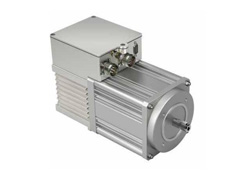
Сервоприводы и моторы. Каталог
-
Приводы и моторы. Презентация
-
Опросный лист на продукцию GEFRAN
-
КАЧЕСТВО
GEFRAN является синонимом качества и опыта в разработках и производстве систем и приводов, благодаря постоянному вниманию на тенденции рынка и непрерывной профессиональной подготовке технического персонала.
-
ТЕХНОЛОГИИ
Кооперация с ведущими исследовательскими центрами и институтами Европы, а также постоянные инвестиции в исследования и разработку позволяют компании держать уровень применяемых технологий выше текущих потребностей рынка.
-
ЭФФЕКТИВНОСТЬ
Имея широкий спектр высокопрофессиональных технологичных продуктов, компания GEFRAN может предложить лучшие индивидуальные решения для оптимизации и повышения эффективности каждого промышленного применения.
-

Безопасные приводы
серия KFM SAFETY и др.
-
Позиционирующие приводы
серия KFM 05A и др.
-
Приводы промышленных дверей
серия KFM09 и др.
-
Бесщеточные моторы
серия SM и др.
-
Приводы для дверей лифтов
серия LD-Drive и др.
Обратитесь к нам или региональному дилеру для получения более подробной информации о сертификатах, характеристиках, отзывах, стоимости, наличии на складе и сроках поставки оборудования GEFRAN.
Мы гарантируем ответ в течение 8 рабочих часов!
адрес для заявок: gnv@nt-rt.ru
Задайте вопрос прямо сейчас:
Enable configuration and calibration as described in the
manual in the Hardware Configuration section (jumpers “S9”
and “S8” closed).
In phase CFG/2 (Configuration 2) set the type of input probe:
parameter tyP:
tyP = 0,1,2,3,4,5 for thermocouples J,K.N.S R,T
tyP = 6,7 for resistance thermometers Pt100
typ = 8,9,10 for linear input 0 ..50mV
typ = 12,13,14 for linear input 10 ..50mV
tyP = 11 for resistance thermometers Pt100 special
case -19.9. .99.9 (199.9)°C with hardware modification.
Quit phase CFG/2; the instrument returns to normal operation.
Proceed to calibration with the instrument ON for at least 5-10
minutes. Calibrate as follows:
A) Calibration of thermocouples J,K,N,S,R,T and linear
input 0-50mV10-50mV.
A.1) Keep the F key pressed until CAL appears on the display;
release F
A.2) Connect a 50.00mV signal from a calibrator between
terminals 1 (+) and 3 (-).
A.3) Press F: the display shows message CAL/50; wait about
6 seconds.
A.4) Press F: the display shows message t.A/25.0; with
the raise and lower keys, set the real value of the room
temperature in which you are performing the calibration
procedure (example: t.A = 23.7°C). You do not have to set the
room temperature for linear inputs
A.5) Press F: the display shows brd/valore; set the hardware
model code (see brd table in CFG.2 phase).
A.6) Press F to end the calibration procedure; the instrument
will return to normal operation.
If the 50mV signal remains in input, the display shows
message _Hi for tyP = 0,1,2,3,4,5 (thermocouples) or
maximum scale for tyP = 8,9,10,12,13,14 (linear scale).
The thermocouple and linear input is now calibrated.
Так то все понятно, но не понятно, какого типа у меня термопара???
Я знаю, что у меня на 100+ градусов больше, чем по факту показывает.
хз, короче.