-
Contents
-
Table of Contents
-
Bookmarks
Quick Links
1435 e Pos
Intelligent Positioner
OPERATING INSTRUCTIONS
GB
Status 01.06.16
From version 2.0.0.3
1435 e Pos
Related Manuals for Gemu 1435 ePos
Summary of Contents for Gemu 1435 ePos
-
Page 1
1435 e Pos Intelligent Positioner OPERATING INSTRUCTIONS Status 01.06.16 From version 2.0.0.3 1435 e Pos… -
Page 2
Quick commissioning of the GEMÜ 1435 ePos: Prerequisites: Mounted to the valve Air supply, max. 6bar, connected 24 V DC supply voltage connected Set value signal need not be connected For correct commissioning proceed as described in the following flow chart:… -
Page 3: Table Of Contents
Contents 10.2.6 Menu structure — Complete overview 10.3 Parameter table General safety information Explanation of parameters General information 11.1 Service Explanation of symbols and signs 11.1.1 Scanning the input and output signals Safety notes 11.1.2 Activating or deactivating the user access Correct use 11.1.3 Reading out, deleting and deactivating error Information on use in damp conditions…
-
Page 4: General Safety Information
Only qualifi ed and trained personnel should The manufacturer shall undertake no responsibility assemble, electrically connect and commission for the GEMÜ 1435 ePos if these safety notes are not the GEMÜ 1435 ePos. Use qualifi ed personnel observed. DANGER for operation, servicing, inspection and assembly.
-
Page 5: Correct Use
Maximum storage temperature: 60 °C. water that remains on the pipework / cables cannot enter the cable glands of the M12 plugs of the GEMÜ 1435 ePos. Check that all cable glands of the M12 plug and the fi ttings 2.4 Function…
-
Page 6: Diagrammatic View Of The Inputs And Outputs
3 Diagrammatic view of the inputs and outputs Additional functions of the positioner: Automatic initialisation Easy to understand help texts for operating in system mode «ADVANCED» Stroke limiter and seal adjuster Close tight function Selectable or settable characteristic curve Safety position «fail safe» Freely programmable alarm outputs Etc.
-
Page 7: Mechanical Mounting
4 Mechanical mounting 1. For control function 1 (normally closed) place the mounting bracket 1 between the actuator head 2 and travel sensor 3 When operating with an actuator of control function and fi x by turning the travel sensor at the hexagon 4. 2 (opened by sping force), fi…
-
Page 8: Remote Mounting
6. Loosen screws on housing cover and swing the cover open. 6 Electrical connections 7. Feed cable from linear travel sensor into the M12 cable gland 6 of the positioner and connect to the terminal board 6.1 Version with terminals (standard) as shown in the wiring diagram (see chapter 6).
-
Page 9: Version With Connector (Optional)
7.2 Operator interfaces Connection Pin Signal name The GEMÜ 1435 ePos off ers a choice of two diff erent operator Uv, actual value supply 10 V DC interfaces ( System mode). These can be selected in the Usig, actual value input 0-10 V DC «SYSTEMMODE»…
-
Page 10: Changing The Operator Interfaces
2. Switch on supply voltage 24 V DC. The GEMÜ 1435 ePos uses two menu levels. These are the 3. Specify an analogue set value 0/4-20 mA or 0-10 V. working level (AUTO and MANUAL) and the confi guration level (CONFIG).
-
Page 11
RUN 2 up -> down 2: INIT RUN 3 down -> up 2: INIT RUN 3 The GEMÜ 1435 ePos positioner is ready for P = XX.X operation and reacts to 2: INIT RUN 4 the externally specified set value. -
Page 12: With Factory Setting
Display Error cause Error elimination Old positioners (up to software Leakage in the system Press V1.3.1.8) Remove leakage Leakage RUN 4 Restart automatic initialisation PRESS <- New positioners (from software Leakage in the system Press V2.0.0.0) Remove leakage Press P = XX.X 2: INIT RUN 5 Press…
-
Page 13: System Mode Classic
9 System mode CLASSIC 9.1 Operating modes 9.1.1 Automatic operation (A:)AUTO) Automatic operation is the normal operating mode. The initialised positioner responds to set value changes and adjusts the valve accordingly.The keys have no function in this operating mode. The current position (x) is shown as a percentage in the display and also as a bar chart. The lower line shows the current operating mode and at the right is the current set value (w) in percent.
-
Page 14: Parameter Table
9.2 Parameter table Display Function Value range Unit Factory setting 0..10V 1:SETPOINT Type of set value 0..20mA 4..20mA 4..20mA NO INIT 2: INIT ALL Starting automatic initialisation – NO INIT Init OK NO DEFAULT 3: DEFAULT STATE Return to factory setting –…
-
Page 15: Explanation Of Parameters
9.3 Explanation of parameters 13: LEVEL ALARM 1 Switch point for Alarm 1. When the switch point has been 1: SETPOINT reached, digital output A1 (24V DC output) is switched. Range of analogue set value input (Voltage: 0-10 V or power: 0/4-20 mA) 14: LEVEL ALARM 2 Switch point for Alarm 2.
-
Page 16
25: SETP RAMP Physical stroke Set value ramp x [%] The set value ramp is eff ective during automatic operation and limits the speed of change of the eff ective set value. When Unlimited stroke switching over from manual to automatic operation the eff ective set value is matched to the set value on the unit via the set value ramp. -
Page 17
Stroke x [%] Linear and Equal-Percentage characteristic control curves Hub x [%] Lineare u. gleichprozentige Kennlinien 120,0 100,0 100,0 100,0 Linear linear 80,0 72,5 67,6 60,0 1:25 52,5 45,7 40,0 38,1 30,9 27,6 1:50 20,9 20,0 20,0 14,5 14,1 10,5 Set value w [%] Sollwert w [%] 42: DeadBand… -
Page 18: System Mode Advanced
10 System mode ADVANCED If the parameter «SYSTEMMODE» is set to «ADVANCED» the menu confi guration is diff erent, as are a certain number of new parameters. To activate the system mode «ADVANCED» the parameter «SYSTEMMODE“ must be changed to «ADVANCED» and then the supply voltage interrupted for more than 3 seconds.
-
Page 19: Confi Guration Menu (Setup)
This menu is used to read out all information/diagnostics regarding the positioner, the connected signals and errors that occur. 2. SetBasics SetBasics is used to set the basic settings for the GEMÜ 1435 ePos such as the initialisation, selection of input signals and resetting to factory settings. 3. SetFunction The special positioner functions are activated or deactivated here and the control parameters set.
-
Page 20: Menu Structure 3. Setfunction
10.2.3 Menu structure 3. SetFunction Level Alarm1 10.0 % Level Alarm2 90.0 % Return Alarm Fn 0.0…100.0 % 0.0…100.0 % min/max min/min max/max Analog Out 0-10V Out max 100.0 % Return Out min 0.0 % 0-20mA * 0.0…100.0 % 0.0…100.0 % 4-20mA * SetFunction Alarm Output…
-
Page 21: Menu Structure — Complete Overview
10.2.6 Menu structure — Complete overview Service SetBasics SetFunction SetCalibration Communication Fieldbus SETP.ANALOG Return SETP.ANALOG SETP.BUS Return X-DIR: RISE SetpDir: NORMAL Setp Ramp: Split Start: 0.0 % Split End: 100.0 % Setp Fn: linear Setp Functn RISE…FALL NORMAL 0…400 s 0.0…100 % 0.0…100 % linear…
-
Page 22: Parameter Table
10.3 Parameter table Config. level Display Function Value range Factory setting read write AUTO Mode Select operating mode AUTO Submenu for displaying inputs and outputs 1 Service Displays travel sensor position in min-Pot-max o.r.* percent I w / Uw Value of set value signal in mA / V o.r.* Comparison of set value and W Pos X…
-
Page 23
Config. level Display Function Value range Factory setting read write Submenu for setting positioner parameters 3 SetFunction Prop Gain P amplification of the positioner 0.1…100.0 Decay time of the D component Deriv Time 0.00…10.00 s 0.1 s of the positioner Seal adjuster = lower position of MinPos 0…100 %… -
Page 24: Explanation Of Parameters
Config. level Display Function Value range Factory setting read write Direction of X display and RISE 4 SetCalibration X-DIR RISE actual value output FALL NORMAL Setp Dir Direction of set value NORMAL INVERS AUTO Setp Ramp Ramp function — set value 0…400 s Split range (set value range) Split Start…
-
Page 25: Activating Or Deactivating The User Access
I / O Status Login The confi guration level of the GEMÜ 1435 ePos is protected in certain areas by various codes against improper changing of parameters. All menu items are marked by symbols indicating their write and read protection.
-
Page 26: Reading Out, Deleting And Deactivating Error Messages
11.1.3 Reading out, deleting and deactivating error messages SETUP Service SetBasics SetFunction SetCalibration Communication I / O Status Login Diagnosis ErrorList: The positioner stores the last 100 error messages in this menu. The errors are also stored during operation in the operator interface » Pos».
-
Page 27: Setbasics
11.2 2 SetBasics SETUP Service SetBasics SetFunction SetCalibration Communication 11.2.1 Defi nition of set value input Setpoint Setting the analogue set value input (Voltage: 0-10 V or power: 0/4-20 mA) 11.2.2 Reset Default Default setting Return to factory setting and resetting initialisation. The parameters D .Refresh and the New Code 1-3 are not taken into account.
-
Page 28
Init All = Man: Manual initialisation When manual initialisation is started, the positioner runs through an initialisation program that is similar to the automatic initialisation. However the diff erent program steps for the manual initialisation must be started and confi rmed by the operator using key. -
Page 29: Making The Display Settings
11.2.4 Making the display settings D .Refresh: The time for display refresh can be changed. System mode: Selection of operator interface CLASSIC – menu confi guration as described in chapter 7.2 System mode ADVANCED – menu confi guration as described in chapter 7.2 System mode DLight: The features of the display lighting can be switched between the following settings: OnKey –…
-
Page 30: Setting The Dead Zone
Physical stroke x [%] Unlimited stroke Limited stroke Set value w [%] The mechanical regulating distance (from limit stop to limit stop) is limited to the set values with the parameters MIN POS and MAX POS. That way the actuator’s mechanical positioning range range can be limited. The parameter setting CLOSETIGHT is higher ranking! CloseTight: ‘Close tight’ variables…
-
Page 31: Setting Alarm Output Functions And Switch Points
11.3.3 Setting alarm output functions and switch points AlarmOutput: Submenu for setting the alarm outputs Alarm Fn: Activates or deactivates the alarm function. The reaction of the alarms ( limiting contacts) () relates to the POSITION measurement (mechanical distance). x = current actual value min/max: Position State output A1…
-
Page 32: Setting Position Feedback Function And Limiting Values
(P1<=P4) Read from P4 to P1 (OFF) Storage function deactivated P1: Memory 1 P2: Memory 2 P3: Memory 3 P4: Memory 4 W: Factory setting The GEMÜ 1435 ePos automatically stores all parameters in working memory P1. 32 / 48 1435 e Pos…
-
Page 33: Setcalibration
11.4 4 SetCalibration SETUP Service SetBasics SetFunction SetCalibration Communication 11.4.1 Setting direction of actual value display X-DIR: Correcting variable direction Here the display direction (rising or falling) and the position feedback can be adjusted. Pressurization state X-Direction Displayed x-value Allocated actual position x Outlet A1 vented RISE…
-
Page 34
Stroke x Set value Set value range Set value range Positioner 1 Positioner 2 Important: The diff erence between the SPLIT START and SPLIT END values must be > 10 %. Setp Functn: Set value function With this function non-linear valve characteristics can be linearised and with linear valve characteristics any fl ow characteristics can be reproduced. -
Page 35
12 Error messages Error Error Warn- Error text Description Condition for the Error clearance occurrence of the error NO ERROR There are no errors Setp.Range The set value signal is out- The positioner is in Check set value signal side the defined range automatic mode Error Run 1 Actuator’s direction cannot… -
Page 36
13 Table for changes to the factory settings Config. level Display Function Factory setting New Code: 1 Release the lowest priority 1 Service New Code: 2 Release the medium priority New Code: 3 Release the top priority Warnings Display warnings during operation Errors Display errors during operation Config. -
Page 37
Config. level Display Function Factory setting Direction of X display and actual value 4 SetCalibration X-DIR RISE output Setp Dir Direction of set value NORMAL Setp Ramp Ramp function — set value Split Start Split range (set value range) start 0.0 % Split End Split range (set value range) end… -
Page 38
17 Technical data General information Travel sensor Protection class to EN 60529 IP 65 Linear design Dimensions L x W x H 160 x 90 x 84 mm Mounting Remote Weight 1.6 kg Stroke 0-30 / 0-50 / 0-75 mm Mounting position Optional Permissible minimum stroke… -
Page 39
18 Order data Fieldbus Code Option Code Without Without Electrical connections M12 5-pin 4-20 mA actual value output 4-20 mA actual value output Accessory Code Electrical connections M12 5-pin Accessory 4-20 mA actual value output and heating element Electrical connections M12 5-pin and heating element Heating element Action Code… -
Page 40
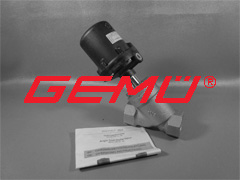
Required parts for direct mounting Linear actuators Quarter turn actuators GEMÜ 1435… (positioner) GEMÜ 1435… (positioner) GEMÜ 1445 000 Z… (mounting kit) GEMÜ 1445 PTAZ… (mounting kit) Note: Mounting kit 1445 000 Z… (plastic spindle, spring, threaded adapter if applicable) depends on the valve type. Please order separately specifying valve type, DN and control function. -
Page 41
Mounting kits for direct mounting — Quarter turn actuators GEMÜ 1445 PTAZ …000… GEMÜ 1445 PTAZ …V… GEMÜ 1445 PTAZ …H… 4 / (2)* 4 / (2)* 2 / (4)* 2 / (4)* Mounting: Mounting: Mounting: Mounting bracket NAMUR adapter V NAMUR adapter H Control air connector code 000 Control air connector code -V-… -
Page 42
Required parts for remote mounting Linear actuators Quarter turn actuators GEMÜ 1435… (positioner) GEMÜ 1435… (positioner) GEMÜ 4232… (travel sensor) GEMÜ 4231… (travel sensor) GEMÜ 4232 S01 Z… (travel sensor mounting kit) GEMÜ 4231 PTAZ… (travel sensor mounting kit) GEMÜ 1445 000 Z MP (mounting bracket) GEMÜ… -
Page 43
Mounting kit for remote mounting — Quarter turn actuators GEMÜ 4231 (travel sensor) GEMÜ 4231 PTAZ (travel sensor mounting kit) Order data — Travel sensor (quarter turn actuators) Cable length Code Field bus Code Without Length 2.0 m 02M0 Length 5.0 m 05M0 Others on request Accessory… -
Page 44
Order data — Mounting kit for travel sensor — Quarter turn actuators Mounting kit Code Measuring range Code Mounting kit for quarter turn actuators PTAZ Angle of rotation 90° NAMUR size Code Control air connector Code Hole spacing 80×30, shaft height 20 Without Hole spacing 80×30, shaft height 30 Hole spacing 130×30, shaft height 30… -
Page 45
19 Fail safe function Fail safe function Error Outlet A1 Outlet A2 Single acting: vented Single acting: non existent Electrical power supply failure Double acting: vented Double acting: pressurized Single acting: vented Single acting: non existent Double acting: undefined, Double acting: undefined, Pneumatic supply failure dependent on the dependent on the… -
Page 46
List of terms General information 4 goClose 28 goOpen 28 AdjTime 22 AD Nozzle 35 ADVANCED 9, 17 ALARM FUNCTN 15 HelpLanguage 22, 29, 36 AlarmOutput 23, 31 HelpText 22, 29, 36 AUTO 10, 18 hrs 22, 26 Automatic initialisation 27 INIT ALL 14, 15 CalPointQty 22, 28 Initialisation 11… -
Page 47
Range Functn 23, 31, 36 Range monitoring 14, 15, 23, 31, 36 Relais 22 Relay 24 RELEASE 14, 17 Reset 27 Reversal of direction 16, 33 Safety 4 Seal adjuster 6, 15, 23, 29, 36 Service 19, 22, 24, 36 SetBasics 19, 22, 27, 36 SetCalibration 19, 20, 24, 33, 37 SetFunction 19, 20, 23, 29, 36… -
Page 48
GEMÜ Gebr. Müller Apparatebau GmbH & Co. KG · Fritz-Müller-Str. 6-8 · D-74653 Ingelfi ngen-Criesbach Telefon +49(0)7940/123-0 · Telefax +49(0)7940/123-192 · info@gemue.de · www.gemu-group.com…
 Конструкция
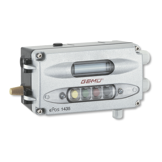
Цифровой электропневматический регулятор положения GEMÜ 1435 ePos® с помощью внешнего датчика перемещения Longlifeопределяет положение клапана. Они имеет прочный корпус с защищенными кнопками управления и хорошо читаемым ЖК-дисплеем. Время позиционирования возможно регулировать с помощью встроенных дросселей. Возможны подключение и монтаж по NAMUR.
Характеристики
• Простое и понятное управление с помощью меню
• Функция автоматической инициализации
• Предохранительная функция при сбое подачи сжатого воздуха или электропитания
• Класс защиты IP 65
• 3/4-проводная технология
• Возможность использования для линейных и поворотных приводов
• Эксплуатация с приводами одностороннего и двустороннего действия
Преимущества
• Раздельный монтаж регулятора и датчика перемещения
• Простота управления и ввода в эксплуатацию
• Простое электрическое подключение посредством съемных клемм
• Автоматическая оптимизация настройки клапана при инициализации
• Отсутствие потребления воздуха в нерабочем положении
Технические данные.pdf
производитель
GEMU
Если вы хотите купить позиционер gemu 1435 , вы можете:
Ещё из раздела Позиционеры

Конструкция GEMÜ 1434 μPos® является цифровым электропневматическим регулятором положения, предназначенным для регулирования промышленных клапанов. Сконструирован для простого, надежного и быстрого использования для клапанов с ходом < …

Конструкция GEMÜ 1436 cPos® представляет собой цифровой электропневматический регулятор положения с опциональным встроенным регулятором процесса, предназначенный для регулирования жидкостей, газов и паров в сочетании с технологическими …

Конструкция GEMÜ 1436 cPos® eco представляет собой цифровой электропневматический регулятор положения с опциональным встроенным регулятором процесса, предназначенный для регулирования жидкостей, газов и паров в сочетании с технологическими …
Цифровой электропневматический регулятор положения GEMÜ 1435 ePos предназначен для управления промышленными клапанами, оснащенными линейными или поворотными пневмоприводами одно- и двустороннего действия. Он регистрирует положение клапана с помощью внешнего датчика перемещения. Он оснащен прочным корпусом с защищенными кнопками управления и ЖК-дисплеем, с помощью которых устройство можно гибко адаптировать к тем или иным задачам по регулированию в индивидуальном режиме. Время установки может регулироваться посредством встроенных дросселей. Возможно соединение и монтаж по стандарту NAMUR. Поэтому GEMÜ 1435 ePos является оптимальным решением для задач по регулированию с жесткими требованиями, особенно при использовании в областях со сложными условиями внешней среды.
Преимущества
- Простота управления и ввода в эксплуатацию
- Простое электрическое подключение посредством съемных клемм
- Автоматическая оптимизация настройки клапана при инициализации
- Отсутствие потребления воздуха в нерабочем состоянии
- Прочный алюминиевый корпус с покрытием
| Характеристика | Значение |
|---|---|
|
Температура среды |
до 60 °C |
|
Рабочее давление |
до 6 бар |
|
Принцип действия |
Двойного действия | Одностороннего действия |
|
Пропускная способность |
50 Нл/мин | 90 Нл/мин |
|
Диапазон измерения:макс |
30 мм, линейный | макс. 50 мм, линейный | макс. 75 мм, линейный | макс. 90°, радиальный |
|
Напряжения электропитания |
24 В= |
|
Соответствия |
EAC |
-

Прайс-лист на продукцию
-
Общий каталог продукции GEMU

-
КАЧЕСТВО
Результат мероприятий по обеспечению качества на всех этапах производства проявляется в ходе эксплуатации оборудования: клапаны и системы регулирования работают надежно, точно и на высоком уровне безопасности.
-
ИННОВАЦИИ
Компания GEMU является одним из лидеров в своем сегменте и сохраняет свои позиции долгие годы. Этого невозможно было бы достичь без активной инновационной деятельности и стремления совершать технологические разработки и достижения.
-
ПРИМЕНЕНИЕ
Продукция компании находит применение в химической, фармацевтической, косметической промышленности, биотехнологиях и других областях. Предприятия в разных странах мира доверяют свои технологические процессы оборудованию GEMU.
-

Затворы поворотные дисковые
410, 411, 415, 417, 423, 428 и др.
-
Регуляторы давления
N082, N085, N086, N182, N185 и др.
-
Шаровые краны
707, 710, 711, 712, 717, 723, 728 и др.
-
Пилотные клапаны
0322, 0324, 0326, 8357, 8458 и др.
-
Электромагнитные клапаны
102, 202, 205, 225, 52, 8253, 8257 и др.
-
Многоходовые клапанные блоки
iComLine и др.
-
Мембранные клапаны
615, 618, 620, R647, R677, R690 и др.
-
Мембранные седельные клапаны
567, C50, C51, C57 и др.
-
Обратные клапаны
560, CV, N560, RSK, ZRSK и др.
-
Седельные клапаны
312, 314, 342, 344, 352, 354 и др.
-
Приводы клапанов
9428, 9468, ADA, ASR, DR, SC и др.
-
Комплектующие
FCP, FCPM, FEPM, FFA, FFBT и др.


Обратитесь к нам или региональному дилеру для получения более подробной информации о сертификатах, характеристиках, отзывах, стоимости, наличии на складе и сроках поставки оборудования GEMU.
Мы гарантируем ответ в течение 8 рабочих часов!
адрес для заявок: gmb@nt-rt.ru
Задайте вопрос прямо сейчас:
![]()
© 2023
Manualzz provides technical documentation library and question & answer platform.Its a community-based project which helps to repair anything.
About us
DMCA / GDPR
Пожаловаться
FixFr.com
Цифровой электропневматический регулятор положения GEMÜ 1435 ePos предназначен для управления промышленными клапанами, оснащенными линейными или поворотными пневмоприводами одно- и двустороннего действия. Он регистрирует положение клапана с помощью внешнего датчика перемещения. Он оснащен прочным корпусом с защищенными кнопками управления и ЖК-дисплеем, с помощью которых устройство можно гибко адаптировать к тем или иным задачам по регулированию в индивидуальном режиме. Время установки может регулироваться посредством встроенных дросселей. Возможно соединение и монтаж по стандарту NAMUR. Поэтому GEMÜ 1435 ePos является оптимальным решением для задач по регулированию с жесткими требованиями, особенно при использовании в областях со сложными условиями внешней среды.
Преимущества
- Простота управления и ввода в эксплуатацию
- Простое электрическое подключение посредством съемных клемм
- Автоматическая оптимизация настройки клапана при инициализации
- Отсутствие потребления воздуха в нерабочем состоянии
- Прочный алюминиевый корпус с покрытием
GEMU
Компания GEMU (Германия) основана в 1964 году и на сегодняшний день является одним из ведущих мировых производителей запорного оборудования, систем контроля и измерения.
все товары бренда
Компания GEMU (Германия) основана в 1964 году и на сегодняшний день является одним из ведущих мировых производителей запорного оборудования, систем контроля и измерения.
Характеристики
| Характеристика | Значение |
|---|---|
|
Температура среды |
до 60 °C |
|
Рабочее давление |
до 6 бар |
|
Принцип действия |
Двойного действия | Одностороннего действия |
|
Пропускная способность |
50 Нл/мин | 90 Нл/мин |
|
Диапазон измерения:макс |
30 мм, линейный | макс. 50 мм, линейный | макс. 75 мм, линейный | макс. 90°, радиальный |
|
Напряжения электропитания |
24 В= |
|
Соответствия |
EAC |
Отзывы и вопросы о товаре
Записей ещё нет — вы станете первым.
Записей ещё нет — вы станете первым.
-
5
0%
-
4
0%
-
3
0%
-
2
0%
-
1
0%