-
Contents
-
Table of Contents
-
Bookmarks
Quick Links
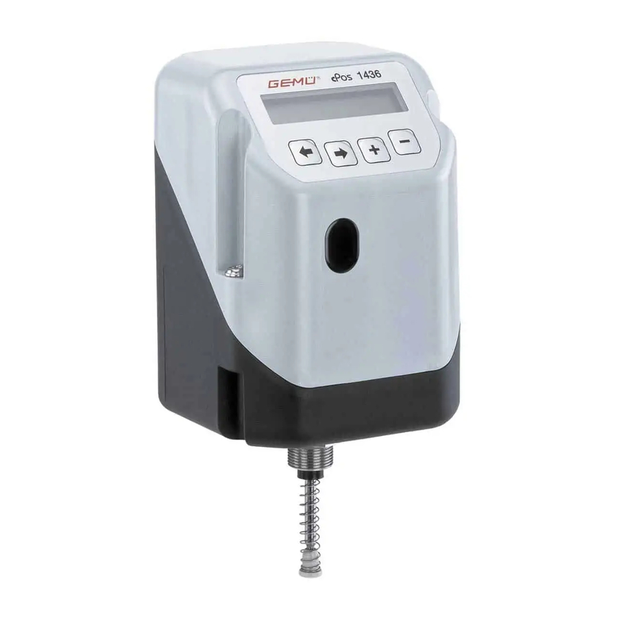
1436 cPos
Intelligent Positioner
and integrated Process Controller
OPERATING INSTRUCTIONS
GB
Status 05.2019
From version 2.0.3.6
1436 cPos
Related Manuals for Gemu 1436 cPos
Summary of Contents for Gemu 1436 cPos
-
Page 1
1436 cPos Intelligent Positioner and integrated Process Controller OPERATING INSTRUCTIONS Status 05.2019 From version 2.0.3.6 1436 cPos… -
Page 2
Quick commissioning of the GEMÜ 1436 cPos: Prerequisites: ● Mounted to the valve. ● Air supply, max. 7bar, connected. ● 24 V DC supply voltage connected. ● Set value and actual value signals need not be connected. ● For correct commissioning proceed as described in the following flow chart:… -
Page 3: Table Of Contents
Control parameters RS232 – Interface 16.4 Adaptation of the controller to the controlled system 45 Operation 16.5 Differential equation for the GEMÜ 1436 cPos Operating and display elements 16.6 Effects of the control parameters on the control Menu levels system 7.2.1…
-
Page 4: General Safety Information
The manufacturer shall undertake no responsibility ● Only qualified and trained personnel should for the GEMÜ 1436 cPos if these safety notes are not assemble, electrically connect and commission observed. the GEMÜ 1436 cPos.
-
Page 5: Correct Use
1.4 Correct use Manufacturer’s information w The GEMÜ 1436 cPos is suitable for use as defined in the data sheet. In order to ensure correct product function, the 2.1 Transport following notes should be observed. Pay attention to the information on the product labels.
-
Page 6: Diagrammatic View Of The Inputs And Outputs
0-20 mA -com 4-20 mA Actual value input for position Communication interface control using the travel sensor Profibus DP / DeviceNet / Profinet Digital inputs (optional) (Function programmable) Supply voltage 24 V DC Operation Keypad 1436 cPos 6 / 66…
-
Page 7: Mechanical Mounting
2. Push the spring over the spindle. 3. Fix the spindle at point a SW27 (the spindle must not be damaged during this process). 4. Screw the operating bush onto the spindle. Travel sensor and actuator 4.1.3 Mounting the positioner Travel sensor mounted on actuator 1436 cPos 7 / 66…
-
Page 8: Mounting To Quarter Turn Actuators
Travel sensor with marking View X, only travel sensor View X, only travel sensor used on positioner in the design with an external travel sensor View X 1436 cPos 8 / 66…
-
Page 9: Mounting The External Travel Sensor (Only For Version With Remote Mounting)
Should the display show that this range is being exceeded, not UV-resistant and must therefore be protected check the mechanical mounting again and readjust the against direct exposure to weather. orientation of the travel sensor, if necessary (see chapter 4.2.2 or 4.2.4). 1436 cPos 9 / 66…
-
Page 10: Remote Mounting To Linear Or Quarter Turn Actuators
1. Connect 24V DC supply voltage to plug X1. 2. Connect analogue input (set value input) 0/4-20 mA to plug 3. If operating as a process controller, connect analogue input (actual value input) 0/4-20 mA to plug X3. 1436 cPos 10 / 66…
-
Page 11: Version With External Actual Value Potentiometer (Code S01)
* Switching output switches device supply voltage Uv — drop voltage ** For options code 01 6.7 Digital inputs The GEMÜ 1436 cPos makes it possible to use digital inputs 6.1 Version with external actual value for specific functions. potentiometer (code S01) It is also available to order with two exclusively digital inputs.
-
Page 12: Use Of Actual Value And Set Value Inputs As Digital Inputs
R=1.2KΩ±5% Pv=1W I-, actual value input 6.8 Digital inputs (optional) The GEMÜ 1436 cPos has four digital inputs when a digital input card is installed. The actual value and set value inputs can be used as digital inputs under the following conditions:…
-
Page 13: Operation
Minus-key Example: The operating mode is to be changed from OFF to Auto. 7.2 Menu levels The GEMÜ 1436 cPos uses two menu levels. These are the working level (Mode) and the configuration level (Setup). 7.2.1 Working level (Mode) The GEMÜ 1436 cPos is automatically at this level after the supply voltage is switched on.
-
Page 14: Commissioning
While doing this, it is possible to choose between automatic initialisation and manual initialisation. When connecting the supply voltage, the following message is displayed by GEMÜ 1436 cPos after it has completed a short software check: NoInit XX.X% ـ…
-
Page 15: Menu Structure Automatic And Manual Initialisation
9.2.3 Menu structure automatic and manual initialisation 1436 cPos 15 / 66…
-
Page 16: Error Messages During Initialisation
«CtrlFn» parameter. If the parameter is set to AUTO, An incorrect control Parameter «CtrlFn» is set for a fixed the 1436 cPos determines the Wrong function function was recognised control function. This set control function corresponding control function and…
-
Page 17: Initial Commissioning With Factory Setting (Positioner Supplied Mounted To The Valve)
9.3 Initial commissioning with factory setting (positioner supplied mounted to the valve) goOpen: The open valve position is scanned during initialisation. If the GEMÜ 1436 cPos was already fully mounted This function must be started with the key if initialising to a valve in the factory, it is already factory manually and then confirmed.
-
Page 18
A manual initialisation should only ever be carried out if you have not achieved satisfactory control characteristics with the automatic initialisation or this was aborted due to an error message. 1436 cPos 18 / 66… -
Page 19: Operating Modes
10 Operating modes 10.5 Test mode (T:) Test mode serves for test purposes to enable quick access to The GEMÜ 1436 cPos uses the operating modes A: AUTO, the basic settings as a positioner. Parameter changes in the M: MANUAL, F: MANUAL-FLEX, T:TEST and OFF.
-
Page 20: Configuration Menu (Setup)
This menu is used to read out all information/diagnostics regarding the positioner, the connected signals and errors that occur. 2. SetBasics SetBasics is used to set the basic settings for the GEMÜ 1436 cPos such as the initialisation, selection of input signals and resetting to factory settings.
-
Page 21
11.3 Menu structure 1 Service 1436 cPos 21 / 66… -
Page 22
11.4 Menu structure 2 SetBasics 1436 cPos 22 / 66… -
Page 23
11.5 Menu structure 3 SetFunction 1436 cPos 23 / 66… -
Page 24
11.6 Menu structure 4 SetCalibration 1436 cPos 24 / 66… -
Page 25
11.7 Menu structure 5 Communication 1436 cPos 25 / 66… -
Page 26
Submenu for displaying the tool identification Displays current software V:1.1.1.1 version Displays current serial S/N xxx number TAG1 11-digit ID number can be set TAG2 11-digit ID number can be set *Only for activated process controllers 1436 cPos 26 / 66… -
Page 27
Safe / ON Determines the function of In 2 ParmSetB0 the digital input «In 2» ParmSetB1 Poti / Ix *Only for activated process controllers ** Parameter value is automatically calculated and set by the positioner during initialisation 1436 cPos 27 / 66… -
Page 28
Delay time between warning Warn. Time recognition and warning 0.0 … 100,0 s 0.0 s message Copies parameters to various CpyParaSet working memories (P1/P2/ P3/P4) Sets the function of analog AnalogOut Poti / Ix Poti output 1436 cPos 28 / 66… -
Page 29
Auto RS 232 Auto connection Serial 38400 Defines the baudrate of the Bdrate RS 57600 115200 RS 232 connection 115200 *Only for activated process controllers ** Only relevant for Profibus DP, DeviceNet or Profinet versions 1436 cPos 29 / 66… -
Page 30: Scanning The Input And Output Signals
All parameters on the control system route must be checked. In w:x:1:2 Displays the current conditions of the digital inputs ( = Signal High). Relay: Displays the current position of the internal relays K1 and K2 ( = Relay switched). 1436 cPos 30 / 66…
-
Page 31: Activating Or Deactivating The User Access
Return Login I / O Status The configuration level of the GEMÜ 1436 cPos is protected in certain areas by various codes against improper changing of parameters. All menu items are marked by symbols indicating their write and read protection.
-
Page 32: Reading Out, Deleting And Deactivating Error Messages
The codes for operation via the RS232-interface can only be assigned, activated or deactivated via the RS232-interface. The codes for direct operation via the GEMÜ 1436 cPos keypad can only be assigned, activated or deactivated via the keypad on the unit itself.
-
Page 33: Setbasics
The help text language may be selected between D-German, GB-English and N-Norwegian. HelpText: The help texts that appear as a default in the second line of the display can be masked. If the help texts are masked, the key assignment is displayed. 1436 cPos 33 / 66…
-
Page 34: Setfunction
Filtered signal input Avr: The actual value input signal is calculated by averaging. Unfiltered signal input Unfiltered signal input IxTime IxTime Filtered signal input Filtered signal input IxTime: Defines the filter time for the actual value input. 1436 cPos 34 / 66…
-
Page 35: Setting The Positioner Parameters
>2.0 (if the characteristic curve is 1:50) or >4.0 (if the characteristic curve is 1:25), in order to shut the valve fully. Current signal for Current signal for Memory which is ParmSetB1 ParmSetB0 read out 1436 cPos 35 / 66…
-
Page 36: Setting Output Functions And Switch Points
Sets the switch point in % under which output K1 is switched. AlarmMaxK1: Sets the switch point in % over which output K1 is switched. SSE1Time: Determines the delay time for output K1 between error recognition and error message for a permanent system deviation. 1436 cPos 36 / 66…
-
Page 37: Setting The Error Time And Error Action
Memory 1 Memory 2 Memory 3 Memory 4 Factory settings The GEMÜ 1436 cPos automatically stores all parameters in working memory P1. 13.3.9 Defining the actual value output AnalogOut: Defining the function of the 4-20 mA actual value output. Poti: The actual valve position is emitted at the 4-20 mA output.
-
Page 38: Setcalibration
>2.0 (for characteristic 1:50) or >4.0 (for characteristic 1:25). SetW-free: Eleven calibration points on the control curve can be programmed as required. Y-Direction: Defines the direction of the process controller output (rising / falling). An inverted process control system can be realized. 1436 cPos 38 / 66…
-
Page 39: Defining The Direction Of The Travel Sensor
Defines the point above which the set value signal activates an error message. I Min X: Defines the point below which the actual value signal activates an error message. I Max X: Defines the point above which the actual value signal activates an error message. 1436 cPos 39 / 66…
-
Page 40: Communication
If you use a connection with a PC/laptop or industrial modem Serial If you use a connection with a PC/laptop Bdrate RS: Defines the baudrate of the serial connection. 38400 baud Bdrate RS 57600 baud 115200 baud (Werkseinstellung) 1436 cPos 40 / 66…
-
Page 41: Error Messages
The positioner is in initialisation mode. leakage and carry out initialisation Error leakage was detected. again. The 1436 cPos tries to change the valve position, but it changes in the wrong ● Leakage in the system A failure of the direction.
-
Page 42: Quick Guide
0-20 mA 4-20 mA 4-20 mA 15.2 Switching the process controller on or off (optional) r0w0 SETUP w XX.X: x XX.X Mode AUTO Automatic operation Automatikbetrieb r0w3 Mode w XX.X: x XX.X Manual operation manueller Betrieb Mode Service SetBasics SetFunction r0w3 ProcCtrlMode: ON…OFF 1436 cPos 42 / 66…
-
Page 43
15.3 Changing the control parameters (Proc P, Proc I, Proc D and Proc T) 1436 cPos 43 / 66… -
Page 44: General Information Regarding Control
16.3 Control parameters Explanation of parameters of GEMÜ 1436 cPos: Derivative action time T It is used to set the intensity of the D component.
-
Page 45: Adaptation Of The Controller To The Controlled System
«manually» by trial and error through experimentation or rule of thumb. Proc D: Slows down the manipulated variable y when Larger: Explanation of parameters of GEMÜ 1436 cPos: moving to the set value. Control is slower. Smaller: Set value is achieved faster. Proc P: K…
-
Page 46: Control Characteristics And Transitory Responses
16.7 Control characteristics and transitory responses Transit function Sprungfunktion Control response Transitory response Regelverhalten Sprungantwort D component I component P component D-Anteil I-Anteil P-Anteil ≈T 1436 cPos 46 / 66…
-
Page 47: Changed Control Parameters
Determines the function of the digital In 1 input «In 1» Determines the function of the digital In 2 input «In 2» K1 Switch Defines the type of output K1 K1 Fn Determines the function of output K1 1436 cPos 47 / 66…
-
Page 48
0/4mA signal Defines the display which corresponds 20 mA ≙ 100 % to a 20mA signal Configuration Display Function Factory settings level Submenu for setting the fieldbus 5 Communication Fieldbus address if available 1436 cPos 48 / 66… -
Page 49: Set Values For The Freely Programmable
Please contact us at the address on the last page for staff training information. Should there be any doubts or misunderstandings in the preceding text, the German version of this document is the authoritative document 1436 cPos 49 / 66…
-
Page 50: Technical Data
— Operating hours counter, event list (for details see Transmission rates 125k / 250k / 500k Baud operating instructions) Profibus DP Parameterisation / process data — Digital inputs (option) for variable function control for Transmission rates 100 M Baud automation 1436 cPos 50 / 66…
-
Page 51: Order Data
22 Order data Note The GEMÜ 1436 cPos positioner can be directly or remotely mounted to linear or quarter turn actuators Direct mounting For direct mounting the following components are required which must be ordered separately: Linear actuators Quarter turn actuators Positioner GEMÜ…
-
Page 52
Order example 1436 SA01 Type 1436 Fieldbus (code) Accessory Action (code) Device version (code) SA01 Options (code) Flow rate (code) Travel length (code) 1436 cPos 52 / 66… -
Page 53
1436S01Z552505000 1436S01Z211503000 4A1-4A3 1436S01Z758605000 15-25 1436S01Z201503000 1436S01Z572505000 15-40 1436S01Z210903000 1436S01Z597105000 15-40 1436S01Z210903000 1436S01Z572505000 32-40 1436S01Z201103000 1436S01Z597105000 1436S01Z201803000 1436S01Z200103000 1436S01Z211503000 1436S01Z201503000 1436S01Z211503000 1436S01Z556005000 687 65-100 1436S01Z551305000 687 65-100 1436S01Z562505000 1436S01Z554805000 1436S01Z255303000 687 65-100 1436S01Z562505000 1),4) 1436S01Z250303000 1436 cPos 53 / 66… -
Page 54
1436S01Z211503000 R690 80-100 1436S01Z551305000 R690 80-100 1436S01Z562505000 R690 80-100 1436S01Z562505000 SUPM 1436S01Z292403000 Footnote 1) For control function DA use double acting positioner (action code 3). 4) For control applications use positioner with K number 2442 1436 cPos 54 / 66… -
Page 55
Hole spacing 80×30, shaft height 30 Hole spacing 130×30, shaft height 30 Hole spacing 130×30, shaft height 50 Order example 1436 PTAZ Type 1436 Mounting kit (code) PTAZ NAMUR size (code) Measuring range (code) Control air connector (code) 1436 cPos 55 / 66… -
Page 56
Order code — 1436 000 ZMP Connection kit GEMÜ 1436 S02 Z… Connection kit GEMÜ 1436 S02 Z… See order data — Connection kit See order data — Connection kit GEMÜ 1436 cPos Positioner GEMÜ 1436 S02Z Connection kit GEMÜ 1446 000 ZMP… -
Page 57
Order example 4232 05M0 4001 Type 4232 Fieldbus Accessory Housing material (code) Travel length (code) Cable length (code) 05M0 Cable connection (code) 4001 1436 cPos 57 / 66… -
Page 58
4232S01Z551705000 32-50 4232S01Z251705000 4232S01Z251503000 4232S01Z211503000 4232S01Z575905000 4232S01Z200303000 4232S01Z211003000 4232S01Z551705000 4232S01Z568905000 4232S01Z251503000 4232S01Z211003000 4232S01Z575905000 4232S01Z201503000 4232S01Z211003000 4232S01Z554605000 4232S01Z568905000 4232S01Z253603000 4232S01Z211003000 4232S01Z253803000 4232S01Z201503000 4232S01Z576205000 4232S01Z554605000 4232S01Z253603000 4232S01Z253603000 4232S01Z256803000 4232S01Z253803000 4232S01Z253603000 4232S01Z576205000 4232S01Z253803000 4232S01Z253603000 4232S01Z576205000 4232S01Z253603000 4232S01Z253803000 4232S01Z576205000 1436 cPos 58 / 66… -
Page 59
K number 2442 32-40 4232S01Z201103000 4232S01Z201803000 4232S01Z211503000 4232S01Z211503000 687 65-100 4232S01Z551305000 687 65-100 4232S01Z562505000 687 65-100 4232S01Z562505000 4232S01Z200103000 4232S01Z575905000 15-25 4232S01Z201503000 15-40 4232S01Z210903000 15-40 4232S01Z210903000 32-40 4232S01Z201103000 4232S01Z201803000 4232S01Z211503000 4232S01Z211503000 4232S01Z251503000 4232S01Z252505000 4232S01Z251503000 4232S01Z252505000 1436 cPos 59 / 66… -
Page 60
Hole spacing 80×30, shaft height 30 Hole spacing 130×30, shaft height 30 Hole spacing 130×30, shaft height 50 Order example 4231 PTAZ Type 4231 Mounting kit (code) PTAZ NAMUR size (code) Measuring range (code) Control air connector (code) 1436 cPos 60 / 66… -
Page 61: Fail Safe Function
(open, close, hold) (open, close, hold) under I Min X) Actual value > 20.0 mA (Range adjustable from 0…22 mA under I Max X) No. 3 and 4 only available for device version code PA01 1436 cPos 61 / 66…
-
Page 62: Application Examples
24 Application examples 24.1 GEMÜ 1436 cPos as process controller with 4-wire transmitter (GEMÜ 3021) 24 V DC 24 V DC 1436 cPos Intelligent positioner Power supply 1436 cPos Intelligenter Stellungsregler Spannungsversorgung Intelligenter Stellungsregler Spannungsversorgung Intelligent positioner power supply Four wire flowmeter 4-Leiter Durchflussmessgeräte 4-Leiter Durchflussmessgeräte four wire flowmeter 4-20 mA…
-
Page 63: Eu Declaration Of Conformity
GEMÜ Gebr. Müller Apparatebau GmbH & Co. KG Fritz-Müller-Straße 6-8 D-74653 Ingelfingen declare that the product listed below complies with the following directive: • EMC Directive 2014/30/EU Product: GEMÜ 1436 Joachim Brien Head of Technical Department Ingelfingen-Criesbach, September 2016 1436 cPos 63 / 66…
-
Page 64: List Of Terms
K1 Fn 28, 47 Digital inputs 11 K1 Switch 11, 28, 36, 47 DigitalOutput 36 K2 Fn 28, 48 Disturbance variable 44 Dlight 33 DLight 33, 47 D.Refresh 27, 33, 47 Leakage 14, 16, 41 Logout 31 1436 cPos 64 / 66…
-
Page 65
ProcCtrlMode 34 X-Input 27, 33, 47 ProcCtrlOut 26 Proc-D 34 Proc-I 27, 34, 47 Proc-P 27, 34, 47 Y-Direction 29, 38, 48 Proc-T 27, 34, 47 Proportional action factor 44, 45 Proportional band 44 Ziegler-Nichols 45 1436 cPos 65 / 66… -
Page 66
GEMÜ Gebr. Müller Apparatebau GmbH & Co. KG · Fritz-Müller-Str. 6-8 · D-74653 Ingelfingen-Criesbach Telefon +49(0)7940/123-0 · Telefax +49(0)7940/123-192 · info@gemue.de · www.gemu-group.com…
|
Detail Specifications: 1493/1493981-1436_cpos.pdf file (21 Nov 2022) |
Accompanying Data:
Gemu 1436 cPos Valve Positioners PDF Operating Instructions Manual (Updated: Monday 21st of November 2022 03:04:24 AM)
Rating: 4.3 (rated by 12 users)
Compatible devices: SVI II AP-2, LCR Series, SX300 Series, ETS-LINDGREN MAPS 2112 Series, 8793, P20, 3760, SmartCal Series.
Recommended Documentation:
Text Version of Operating Instructions Manual
(Ocr-Read Summary of Contents, UPD: 21 November 2022)
-
21, 21 / 66 1436 cPos 11.3 Menu structure 1 Service Diagnosis 1.3 Service 1 ID 255.255.255.255 hrs. XXXXX:XX:XX I w: XX.X mA I / O Status 1.1 S/N 743984/ 1 Seriennummer Gemü specific 1.4 Return Proc Ctrl Out I x: XX.X mA W Pos X XX.X % XX.X% Relais K1 : K2 Return 1.5 Return Valve …
-
39, 39 / 66 1436 cPos 13.4.3 Dening the direction of the travel sensor Pot Dir: The direction of the actual value potentiometer can b e dened. Rise: For valves with rising direction of action ܟ Linear actuators: Valve spindle rises when valve opens ܟ Quarter turn actuators: Viewed from above, shaft turns anticlockwise when valve opens Fall: For valves with fal…
-
8, 8 / 66 1436 cPos 4.2 Mounting to quarter turn actuators 4.2.1 Preparation of the valve actuator 10 0° / CLOSED 90° / OPEN 1. The actuator must be in the zero position (actuator ven- ted). Double acting actuators should be moved to the valve «CLOSED» position. 2. Remove the screw 10 which retains the optical position indicator. 3. Determine the turn direction of the actuator…
-
53, 53 / 66 1436 cPos B Order data — Mounting kit for linear actuators Type DN Control func tion Actuator size Travel length Footnote Order number 550 3 1 030 1),4) 1436S01Z250303000 550 3 2 030 1) 1436S01Z255303000 550 3 4 050 1) 1436S01Z571705000 550 3 5 050 1) 1436S01Z574305000 550 15-25 1 3 030 1436S01Z203603000 550 15-25 3 3 030 1) 1436S01Z251803000…
-
59, Gemu 1436 cPos 59 / 66 1436 cPos G Order data — Mounting kit for linear actuators Footnote 1) Use double acting positioner for control functions DA or DA-NO in combination with a positioner 2) For control function NO in combination with type 1435 also order pneumatic throttle 1435DR-Z 3) For control applications use positioner with K number 2443 4) For control applications use po…
-
36, Gemu 1436 cPos 36 / 66 1436 cPos Before a dierent parameter set can be loaded, it must rst be copied to the appropriate memory (see chapter 13.3.7 CpyParamSet). If a digital input (In W, In X, In 1 or In 2) is set to the OFF / ON or Safe / ON function and the digital signal «High» is not connected, the following messages will be displayed: In 1 no Signal: The …
-
2, 2 / 66 1436 cPos Quick commissioning of the GEMÜ 1436 cPos: Prerequisites: ● Mounted to the valve. ● Air supply, max. 7bar, connected. ● 24 V DC supply voltage connected. ● Set value and actual value signals need not be connected. ● For correct commissioning proceed as described in the following ow chart: Automatic fast initialisation The initialisation can alterna…
-
62, 62 / 66 1436 cPos 24 Application examples 24.1 GEMÜ 1436 cPos as process controller with 4-wire transmitter (GEMÜ 3021) + + + + + — — — — — 24 V DC Spannungsversorgung power supply 1436 cPos Intelligenter Stellungsregler Intelligent positioner 4 — 20 mA Istwert actual value 4-Leiter Durchflussmessgeräte four wire flowmeter 4 — 20 mA Sollwert setpoint GEMÜ Sitz- / Membranventi…
-
26, Gemu 1436 cPos 26 / 66 1436 cPos 12 Parameter table Configuration level Display Function Value range Factory setting Mode Select operating mode AUTO MAN MAN-FLEX TEST OFF AUTO 1 Service Submenu for displaying inputs and outputs I / O Status ActiveParaSet Displays the current active parameter set P1 … P4 P1 min-Pot-max Displays travel sensor position in percent I w Value of set value signal in mA I x…
-
43, 43 / 66 1436 cPos 15.3 Changing the control parameters (Proc P, Proc I, Proc D and Proc T) SetFunction 3 ProcCtrlMode: OFF ON…OFF r0w3 ProcCtrl Proc-P: 0.50 0.1…100.0 Proc-I: 2,0 s 0,1…999,9 s Proc-D: 0.0 0.0…100.0 Proc-T: 1000 ms 1…10000 ms r0w3 r0w3 r0w3 r0w3 Service 1 Mode AUT…
-
6, 6 / 66 1436 cPos 3 Diagrammatic view of the inputs and outputs Additional functions of the positioner: ܟ Automatic initialisation ܟ Easy to understand help texts ܟ Limitation of opening and closing stroke ܟ Close tight function ܟ Selectable or settable characteristic curve ܟ Safety position «fail safe» ܟ Freely programmable alarm outputs ܟ…
-
11, Gemu 1436 cPos 11 / 66 1436 cPos X1 X3 X2 1 5 43 2 1 5 43 2 1 5 43 2 Connection Pin Signal name X1 M12 plug A coding 1 Uv, 24 V DC supply voltage 2 Switching output K1, 24 V DC (switches Uv*) 3 GND, (supply voltage, DigIn1+2+W+X; K1+2) 4 Switching output K2, 24 V DC (switches Uv*) 5 Digital input 1 (optional**) Connection Pin Signal name X2 M12 plug B coding 1 I+, actual value output 2 …
Recommended Instructions:
RT30G, ABYA30LBT, Sonic 2015, VANTAGE SUB, 2910al-24g, XB24-10


-
Soldo S.r.l. Via Monte Baldo, 60 25015 Desenzano d/G (Brescia) Italy Tel +39 030 999.13.09 — Fax +39 030 914.19.77 http: //www.soldo.net e-mail: [email protected] Installation & Operating Manual IOM-SW_SY01-00 SW SY IOM-SW_SY01-00 Page 1 / 2 READ THIS INSTRUCTION FIRST To avoid serious or fatal personal injury or major property damage, read and follow all safety inst …
SW Series 2
-
MOTION | POSITIONINGPI miCos GmbH, Freiburger Strasse 30, 79427 Eschbach, GermanyPhone +49 7634 5057-0, Fax +49 7634 5057-99, Email [email protected], www.pi.wsVersion: 3.0.0 Date: 18.12.2019User InformaonThese short instrucons contain an overview of the most important safety and handling instruc-ons for installing posioners with NEXACT® drives with the product numbers specied …
NEXACT Stage N-565 Series 4
-
Instruction Manual PSx3xxDP halstrup-walcher GmbH Stegener Straße 10 D-79199 Kirchzarten, Germany Phone: +49 (0) 76 61/39 63–0 Fax: +49 (0) 76 61/39 63–99 E-Mail: [email protected] Internet: www.halstrup-walcher.com Document 7100.003964 03/2017 …
PS*3**DP series 31
Additional Information:
Popular Right Now:
Operating Impressions, Questions and Answers:
Gemu Manuals and Guides:
The main types of Gemu 1436 cPos instructions: user guide — rules of useing and characteristics, service manual — repair, diagnostics, maintenance, operation manual — description of the main functions of Gemu 1436 cPos equipment, etc.
Most of the instructions, that you can see on the site are uploaded by our users. If you have available a manual or document for Gemu 1436 cPos, which is currently not on the site or present in a different language version, we ask you to upload your document on website, using the «uploading form» available to all registered users.
 Конструкция
GEMÜ 1436 cPos® представляет собой цифровой электропневматический регулятор положения с опциональным встроенным регулятором процесса, предназначенный для регулирования жидкостей, газов и паров в сочетании с технологическими клапанами с пневматическим управлением. Регулятор положения точно управляет ходом технологического клапана. Поступающие от датчика сигналы параметров технологических процессов (например, объемного расхода, уровня заполнения,давления, температуры) считываются и подстраиваются опционально встроенным регулятором процесса согласно заданным параметрам.Мембранная клавиатура и дисплей с фоновой подсветкой расположены на передней панели в корпусе. Подключения к системам подачи электропитания и сжатого воздуха компактно расположены в задней части.Встроенные пневматические дроссели позволяют регулировать воздушный поток таким образом, чтобы регулятор можно было настроить для различных приводов клапанов и скоростей регулирования.
Характеристики
• Возможно применение для линейных и поворотных приводов однои двустороннего действия
• Многоточечная калибровка для оптимального регулирования клапанов
• Регуляторы процесса и положения точно адаптированы друг к другу
• Параметризация в рабочем режиме
• Оптимизированная инициализация и регулирование клапана(функция speedAP)
• Возможен прямой и раздельный монтаж регулятора на технологический клапан
Преимущества
• Цифровые входы (опция) для регулируемого управления функциями для автоматизации
• Интерфейсы полевой шины, например Profibus DP, DeviceNet (опция)
• Отсутствие потребления воздуха в нерабочем положении
• Простота адаптации к самым различным приводам клапанов
• Права доступа по уровням пользователей
• Встроенный веб-сервер
• Простой ввод в эксплуатацию и различные возможности эксплуатации
— клавиатура на передней панели
— подключение компьютера с браузером MS® Internet Explorer
• Интерфейс e.sy-com для подключения промышленного модема
• Дополнительный модуль Bluetooth
Технические данные.pdf
 |
[Page 1] Gemu 1436 cPos 1436 cPos ® 1436 cPos ® Intelligenter Stellungsregler ORIGINAL QUICK GUIDE DE Ab Version / Intelligent Positioner QUICK GUIDE GB from version 2.0.3.0 |
 |
[Page 2] Gemu 1436 cPos 1436 cPos ® 2 / 24 Inhaltsverzeichnis 1 Hinweise zu Ihrer Sicherheit 2 2 Mechanischer Anbau 2 2.1 Anbau an Hubantriebe 2 2.1.1 Vorbereitung des Ventilantriebs 2 2.1.2 Komplettierung des Weggebers 2 2.1.3 Anbau des Stellungsreglers 3 2.2 A… |
 |
[Page 3] Gemu 1436 cPos 1436 cPos ® 3 / 24 2.1.3 Anbau des Stellungsreglers 1 2 3 G Stellungsregler 1 durch einschrauben des Weggeber-Sechskants M27 2 in Antrieb 3 einschrauben. VORSICHT Der Regler darf nicht durch Drehen des Gehäuses befestigt werden, da sonst die … |
 |
[Page 4] Gemu 1436 cPos 1436 cPos ® 4 / 24 2.2.3 Anbau des Stellungsreglers G Adapter 4 auf Welle des Weggebers setzen. G Stellungsregler mit Weggeber und Haltewinkel auf Antrieb aufsetzen. G Nase von Adapter 5 muss in Nut von Antriebswelle einrasten. G Haltewinkel… |
 |
[Page 5] Gemu 1436 cPos 1436 cPos ® 5 / 24 2.3.5 Anschluss des Weggebers Den 5-poligen M12-Stecker des Weggebers mit der 5-poligen M12-Buchse des Reglers verbinden. 3 Pneumatische Anschlüsse G Verbindung zwischen pneum. Stellungsreglerausgang A1 (einfachwirkend) bzw…. |
 |
[Page 6] Gemu 1436 cPos 1436 cPos ® 6 / 24 * Schaltausgang schaltet Geräteversorgungsspannung Uv — Dropspannung ** Bei Optionen Code 01 und 03 4.2 Profibus DP X1 X3 X2 1 5 43 2 1 5 43 2 1 5 43 2 Anschluss Pin Signalname X1 M12-Stecker B-Kodierung 1 n.c. 2 RxD/TxD-N (PB-… |
 |
[Page 7] Gemu 1436 cPos 1436 cPos ® 7 / 24 Contents 1 Notes for your safety 7 2 Mechanical mounting 7 2.1 Mounting to linear actuators 7 2.1.1 Preparation of the valve actuator 7 2.1.2 Assembling the travel sensor 7 2.1.3 Mounting the positioner 8 2.2 Mounting … |
 |
[Page 8] Gemu 1436 cPos 1436 cPos ® 8 / 24 2.1.3 Mounting the positioner 1 2 3 G Mount the positioner 1 by screwing the travel sensor hexagonal nut M27 2 into the actuator 3. CAUTION The positioner must not be fi xed by turning the housing as this may result in the … |
 |
[Page 9] Gemu 1436 cPos 1436 cPos ® 9 / 24 2.2.3 Mounting the positioner G Place the adapter 4 on the shaft of the travel sensor. G Place the positioner with the travel sensor and mounting bracket onto the actuator. G The adapter lug 5 must engage in the actuator sh… |
 |
[Page 10] Gemu 1436 cPos 1436 cPos ® 10 / 24 3 Pneumatic connections G Make the connection between pneumatic positioner outlet A1 (single acting) or A1 and A2 (double acting) and the pneumatic actuator air control inlet. G Connect the control air supply (additional ai… |
 |
[Page 11] Gemu 1436 cPos 1436 cPos ® 11 / 24 * Switching output switches device supply voltage Uv — drop voltage ** For options code 01 and 03 4.2 Profibus DP X1 X3 X2 1 5 43 2 1 5 43 2 1 5 43 2 Connection Pin Signal name X1 M12 plug B coding 1 n.c. 2 RxD/TxD-N (PB-) 3 n…. |
 |
[Page 12] Gemu 1436 cPos 1436 cPos ® 12 / 24 5 Initialisierung und Inbetriebnahme Durch das Starten der Selbstinitialisierung passt sich der Regler an das Ventil an. Sämtliche Parameter werden selbständig abgefragt. Dieser Vorgang kann je nach Ventil ein paar Minuten… |
 |
[Page 13] Gemu 1436 cPos 1436 cPos ® StartInitValve 3 Sekunden drücken OK ESC Init Valve ESC OK 13 / 24 Automatische Schnell-Initialisierung Der Stellungsregler GEMÜ 1436 cPos ® ist betriebsbereit und reagiert auf den extern vorgegebenen Sollwert. Bei Option «P… |
 |
[Page 14] Gemu 1436 cPos 1436 cPos ® Diagnosis 1.3 Service 1 ID 255.255.255.255 hrs. XXXXX:XX:XX I w: XX.X mA I / O Status 1.1 Gemü specific 1.4 I x: XX.X mA Relais K1 : K2 Return 1.5 W Proc X … |
 |
[Page 15] Gemu 1436 cPos 1436 cPos ® S/N 743984/ 1 Seriennummer Return Proc Ctrl Out W Pos X XX.X % XX.X% Return Valve 1 : 2 : 3 : 4 Errors ON ON…OFF NewCode:3 0 0…10000 l Mode: ON C trlMode: ON Nur verfügbar bei P… |
 |
[Page 16] Gemu 1436 cPos 1436 cPos ® Return W-Input: 4-20 mA 0-20 mA 4-20 mA X-Input: 4-20 mA 0-20 mA 4-20 mA p Default: Yes Yes…No r0w3 r0w3 r3w3 SetBasics 2 Helptext ON … |
 |
[Page 17] Gemu 1436 cPos 1436 cPos ® Init Valve Init Valve Auto Man ESC CalPointQtyt 9 1…19 D. Refresh 0.1 s 0.1…1.0 s AutoReturn 5min 1…60min r3w3 r3w3 r0w1 DLight On… |
 |
[Page 18] Gemu 1436 cPos 1436 cPos ® PosCtrl SetFunction 3 ProcCtrl Return Nur verfügbar bei ProcCtrlMode: ON Only available when ProcCtrlMode: ON Pos P 1.0 0.0…100.0 Proc-P: 0.50 0.1…100.0 Pos D 1.0 0.0…100.0 Proc-I: 2,0 s 0,1…999,9 s ProcCtrlMode: OFF ON…OFF K1… |
 |
[Page 19] Gemu 1436 cPos 1436 cPos ® AlarmMinK2 10.0 % 0.2…99.8 % AlarmMaxK1 10.0 % 0.2…99.8 % AlarmMinK1 10.0 % 0.2…99.8 % Proc-T: 1000 ms 1…10000 ms DigitalOutput Return Return Return Error Time 0.2 s 0.5…100 s CpyParaSet OFF P1<=W P1=>P2 P1<=P2 P1=>… |
 |
[Page 20] Gemu 1436 cPos 1436 cPos ® W0% 0.0% 0.0…100.0 % SetCalibration 4 Return Return Set W-free X-Direction: rise rise…fall W-Direction: rise rise…fall W 90% 90.0 % 0.0…100.0 % W 70% 70.0 % 0.0…100.0 % W 50% 50.0 % 0.0…100.0 % W 100% 100.0 % 0.0…100.0 % W … |
 |
[Page 21] Gemu 1436 cPos 1436 cPos ® OutMinPos 0.0 % 0.0…100.0 % W 10% 10.0 % 0.0…100.0 % W 40% 40.0 % 0.0…100.0 % W 20% 20.0 % 0.0…100.0 % W 30% 30.0 % 0.0…100.0 % OutMaxPos 100.0 % 0.0…100.0 % r0w3 r0w3 r0w3r0w3 r0w2 r0w2 PotiDir rise rise fall r0w3 I Max W 20… |
 |
[Page 22] Gemu 1436 cPos 1436 cPos ® Communication 5 WebServer 5.2 r0w3 RS 232 Auto Auto Serial Fieldbus 5.1 Return r0w3 Fieldbus OFF ON / OFF Bdrate RS 115200 38400 57600 115200 r0w3 ComPort Bluetooth Bluetooth 22 / 24 6.5 Menüstruktur 5. Communication 6.5 Menu structure… |
 |
[Page 23] Gemu 1436 cPos 1436 cPos ® ReturnBT Code 0000 0000…9999 BT Name 1436 cPos StateBT Function PC/PDA PC/PDA Phone Nur verfügbar bei Regler-Ausführung mit integrierter Bluetooth-Schnittstelle 23 / 24 Nur verfügbar bei Reglerausführung mit integrierter Bluetooth-… |
 |
[Page 24] Gemu 1436 cPos Hinweis: Handhabung, Montage und Inbetriebnahme, sowie Einstell- und Justierarbeiten, dürfen nur von autorisiertem Fachpersonal durchgeführt werden. Für Schäden, welche durch unsachgemäße Handhabung oder Fremdeinwirkung entstehen, ü… |