- Manuals
- Brands
- Endress Manuals
- Portable Generator
- ESE Series
- Translation of the original operating manual
-
Contents
-
Table of Contents
-
Troubleshooting
-
Bookmarks
Quick Links
ESE power generator
TRANSLATION OF THE ORIGINAL OPER-
ATING MANUAL
ESE 1008 HG ES Diesel Silent
ESE 1408 DHG ES Diesel Silent
Article-Nos: 113041 / 113040 / 8008015
Related Manuals for Endress ESE Series
Summary of Contents for Endress ESE Series
-
Page 1
ESE power generator TRANSLATION OF THE ORIGINAL OPER- ATING MANUAL ESE 1008 HG ES Diesel Silent ESE 1408 DHG ES Diesel Silent Article-Nos: 113041 / 113040 / 8008015… -
Page 2
This documentation and parts thereof are subject to copyright. Any use or modi- fication beyond the restrictions of the Copyright Act is forbidden and subject to penalty without the consent of ENDRESS Elektrogerätebau GmbH. This applies in particular to copies, translations, microfilming, as well as storage and processing in electronic systems. -
Page 3: Table Of Contents
Welcome to ENDRESS! ……..
-
Page 4
Inteli-Nano …………. .53 ECOtronic (idle down) . -
Page 5: Directories
Directories Directories List of illustrations Fig. 3-1 Example of a type plate Fig. 3-2 Generator’s scope of delivery Fig. 3-3 Document and tool kit compartment Fig. 3-4 Labels on the device Fig. 6-1 Views of the generator Fig. 6-2 Generator and control side components Fig.
-
Page 6: About This Manual
About this manual About this manual We would like to explain to you the safe and correct use of your generator in the best possible way through this operating manual. To do this we have oriented ourselves to the new European standard DIN EN 82079-1 for preparing the user manuals.
-
Page 7
About this manual the required distinctive warning notices at the correct point in time without impair- ing the legibility and comprehensibility of the operating manual. This is according to the regulations contained in the international standard DIN ISO 3864 de- scribes a fixed rule for all safety and warning notices, as shown in the following example. -
Page 8
About this manual Additional notices for operation or for function of a unit are marked with the adjacent symbol. NOTICE! The adjacent symbol is situated anywhere where the supplier documenta- tion must be read and observed and refers to, ► appropriate information, ►… -
Page 9: Product Identification
Product identification Product identification Welcome to ENDRESS! We are pleased that you have made the decision to purchase a ENDRESS power generator. You have purchased a high-performance product into which we have embodied decades of our experience and have integrated many functions oriented on daily use.
-
Page 10: Foreseeable Misuse
Product identification The unit generates AC (three-phase) current with a nominal voltage of 400V at 50Hz. More detailed technical data can be found in Chapter 13 . An integrated voltage regulator ensures that the stability of the generated voltage is within the nominal rotational speed range.
-
Page 11
Product identification • Never refuel the generator’s own tank when it is hot. Overflowing fuel and ex- haust fuel vapours can ignite on hot parts of the device. • Never open the generator’s tank cover whilst it is running or if it is hot. Over- flowing hot fuel and escaping fuel vapours can ignite on the device’s hot parts. -
Page 12: Included In Delivery
Product identification included in delivery 3.3.1 Generators Apart from the technical documentation listed in Chapter 2.1 the following items are also Scope of delivery of your generator: Included with deliv- Fig. 3-2 Generator’s scope of delivery Item Name Oil drainage hose Engine operating and maintenance manual These supplied products can be found in a separate storage compartment der the engine hood…
-
Page 13: Labels On The Generator
Product identification Labels on the generator An important part of the operating manual is the labelling and notices on your generator. These Labels must not be removed and must always be maintained in legible condition. If there is damage to a Labels can be ordered from our cus- tomer service team.
-
Page 14
Product identification Item Name Meaning Mandatory signs Lifting device must only be attached here (loading eye) Note Oil drainage hose feed- through Warning symbol Do not touch — hot surface when running Note Fill the air filter housing with oil before the initial start-up Mandatory signs Read the operating manual before starting up… -
Page 15
Product identification Item Name Meaning Note Noise emissions Note Earthing / potential equalisation con- nection EMERGENC-STOP smash button, see Chapter 7.7 Tab. 3-1 Labels on the device… -
Page 16: For Your Safety
For your safety For your safety The following chapter describes basic Safety instructions for safe operation of your generator. Your device is a very high-performance electrical machine which is potentially dangerous when operated if it has not been installed, commis- sioned, used, serviced and repaired according to the operating manual.
-
Page 17
For your safety Warning of corrosive substances This warning symbol indicates activities where a risk of chemical burns to the en- vironment as well as people exists, possibly with lethal consequences. Warning of environmentally damaging substances This warning symbol indicates activities where a risk of contaminating the envi- ronment exists, possibly with catastrophic consequences. -
Page 18: General Safety Instructions
Residual risks As a manufacturer of EU-compliant machines, ENDRESS make great ef- forts to create designs which already eliminate possible risk potentials at the design stage. If this is not possible without significantly impairing the functions of a device, we implement suitable protective measures protect the user from injury.
-
Page 19
For your safety four different danger levels in order to be able to reliably assess the dan- gers associated with the individual operating states and action steps when reading the operating manual. DANGER! DANGER describes a danger which represents a high level of risk,which can lead to death or severe injuries,when not avoided. -
Page 20
For your safety DANGER! Engine exhaust gases contain poisonous and partially invisible gases such as carbon monoxide (CO) and carbon dioxide (CO2). Risk of death due to poisoning or asphyxiation. ► Ensure that there is good ventilation during the whole period of operation. ►… -
Page 21
For your safety WARNING! Escaping corrosive acid fumes or sulphuric acid during and after the charging process. A risk of suffering severe or even deadly burns. ► Only work with acid-resistant protective equipment. ► Clean surfaces covered in acid immediately using adequate amounts of wa- ter. -
Page 22
For your safety NOTICE! Excessive heat or moisture can destroy the device. ► Always ensure that there is a good supply of air and heat removal. ► Never operate the generator in rooms or narrow pits. ► Never clean the device with the aid of a strong jet of water or high pressure cleaner. -
Page 23: Authorised Operating Personnel — Qualifications And Obligations
For your safety Authorised operating personnel – qualifications and obligations Your Generators is a complex machine, the operation and maintenance of which requires exact knowledge of its functions and danger potentials. Therefore any work with or on the device, of any kind, may only be per- formed by authorised and instructed operating personnel.
-
Page 24
For your safety Product’s service life phase Danger zone Transport and installation within a radius of 1m around or below the de- vice Operation within the outer limits of the device Service and maintenance Within the outer limits of the device when switched on Generators Tab. -
Page 25: Checking The Electrical Safety
Checking the electrical safety Checking the electrical safety Checking of electrical safety requires different measures to be taken which may only be undertaken by respectively authorised personnel. In doing so the respective, pertinent VDE provisions, EN and DIN standards, in their re- spectively valid versions, must be observed.
-
Page 26
Checking the electrical safety NOTICE! The operator is responsible for defining and adhering to the test intervals . Above all one must ensure observance of the respectively valid national regulations. This responsibility also extends to any additional equipment installed in conjunction with the device. -
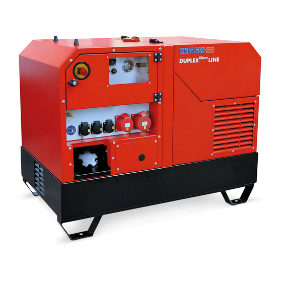
Page 27: Description Of The Device
Description of the device Description of the device Power generator view The following section provides an overview of the name and location of the most important components in your Generatorss. It is important that you become familiar with them in order to understand the functions and oper- ating steps explained below and to be able to implement them safely.
-
Page 28: Generator And Control Side Components
Description of the device Generator and control side components Fig. 6-2 Generator and control side components Crane loading lug Air intake Feedthrough for external refuelling Generator cooling air intake Filling opening Fuel tank Control panel Control panel flap EMERGENCY STOP smash button…
-
Page 29: Engine And Tank Side Components
Description of the device Engine and tank side components Fig. 6-3 Engine and tank side components Engine hood with exhaust outlet Maintenance cover 12V starter battery Feedthrough for oil drainage hose Exhaust outlet Engine cooling exhaust outlet Engine maintenance cover Engine air filter Document compartment with Tool kit Drive engine…
-
Page 30: Control Panel Components
Description of the device Control panel components Fig. 6-4 Control panel components Operating hours counter Tank indicator Battery charge indicator lamp Oil pressure indicator lamp CEE400V/ 32A/3~ socket 400V/ 16A/3~ CEE socket Schuko230V/ 16A/1~ socket Remote start CPC socket Connection Potential equalization / 400V / 16A / 3~ circuit breaker for sock- earthing 400V / 32A / 3~ circuit breaker for CEE…
-
Page 31: Commissioning
Commissioning Commissioning The following chapter explains the basic procedure for initial or repeated generator start-ups in «Manual» mode. Follow the working steps described below when you put your generator into operation for the first time or re- start it again after transporting it. Initial start-up Fig.
-
Page 32
Commissioning the generator must be switched off the generator must be cooled down if fitted, the fuel valve must be in the “OFF” position if connected, the external refuelling device must be disconnected NOTICE! Leaking engine oil and operating fluids can contaminate the soil and groundwater. -
Page 33: Refuelling Your Generator
Commissioning Refuelling your generator Proceed as follows to fit its generator’s own tank: the generator. Conditions The generator is turned off. The generator has cooled down. There must be an adequate air supply and air removal. All power consuming equipment must be disconnected or switched off. DANGER! Leaking engine oil and fuel can burn or explode.
-
Page 34: Starting The Generator
Commissioning Starting the generator Starting the generator for manual operation and with fuel supplied from its own tank is explained here. For automatic remote starting, see Chapter 8.2 , for refuelling using an external refuelling device, see Chapter 8.4 . DANGER! Leaking engine oil and fuel can burn or explode.
-
Page 35
Commissioning Fig. 7-2 Starting the generator Proceed as follows to manually start the generator from its control panel (to start via a remote control, see Chapter 8.2 ): Conditions the electrical safety has been checked (see Chapter 5 ). … -
Page 36: Low Load Diesel Engine Operation
Commissioning NOTICE! Do not apply load to the generator immediately after a cold start. ► Allow the generator engine to warm up for a few minutes before switching on a load when the generator has not been operating for more than eight hours (or for very low external temperatures).
-
Page 37: Turning Off Your Power Generator
Commissioning Turning off your power generator CAUTION! Certain surfaces on the device can get very hot whilst it is running. Risk of burns ► Never touch any engine parts (in particular the exhaust system) for a few min- utes after ceasing operation. ►…
-
Page 38: Turn Off Your Generator In The Event Of An Emergency
Commissioning Turn off your generator in the event of an EMER- GENCY Your power generator is fitted with an EMERGENCY STOP smash button. It enables you to immediately switch the device off in an EMERGENCY. CAUTION! The EMERGENCY-STOP smash button is only to be used in the event of a dangerous situation arising in an emergency.
-
Page 39: Connection Of Power Consuming Equipment
Commissioning Connection of power consuming equipment DANGER! Mortal danger due to an electric shock if live parts are touched. ► Never operate the device if it is in a damaged condition. ► Never operate the electrical consumers and connecting cable (power con- suming equipment) in a damaged condition.
-
Page 40
Commissioning CAUTION! Danger due to malfunctioning of the protective measures against hazard- ous shock voltages with an extended supply network! ► Keep the length of the connecting line as short as possible. ► Use as few sub-distributions as possible. ► Take note of the table below. Line max. -
Page 41: Optional Fittings
Optional fittings Optional fittings The following chapter describes the function and operation of optional equipment features that you either ordered from the factory or purchased later on as accessories. Use your order documents to check which options were fitted to your gen set. Residual current circuit breaker (RCD) The residual current circuit breaker (RCD) protects against dangerous body currents in compliance with DIN VDE 0100-551.
-
Page 42: Remote Start Device
Optional fittings Fig. 8-1 FI circuit breaker (RCD) Testing the RCD The generator is running 1. Move the FI circuit breaker Fig. 8-1 into position. 2. Press the test button Fig. 8-1 The switch position Fig. 8-1 indicates the result: Symbol Meaning POS I…
-
Page 43
Optional fittings All consumer are switched off or disconnected from the generator. Connecting up a re- Proceed as follows to connect up a cable remote control (not included in mote start device the package). 1. Unscrew the protective cap on the CPC remote start socket Fig. 6-4 the counter-clockwise direction. -
Page 44: Wireless Remote Control
Optional fittings NOTICE! Ensure that the generator’s engine start switch (Fig. 6-4 remains in the “STOP“ position. Otherwise the control circuit on the generator will still be energized which can cause the starter battery to discharge. Disconnecting the Proceed as follows to disconnect the cable remote control after the gener- remote start device ator has been switched off: 1.
-
Page 45
Optional fittings Fitting the radio ae- Proceed as follows to connect up the radio aerial. rial 1. Unscrew the protective cap on the CPC remote start socket Fig. 6-4 in the counter-clockwise direction. 2. Insert the plug on the radio aerial’s connecting cable into the correct po- sition in the CPC remote start socket. -
Page 46: Refuelling Device Connection
Optional fittings Disconnecting the Proceed as follows to disconnect the radio aerial after the generator has radio aerial been stopped: 1. Turn the plug’s locking ring counter-clockwise until the lock is released. 2. Now pull out the cable remote control’s plug. 3.
-
Page 47
Optional fittings Fig. 8-5 Refuelling device connection Proceed as follows to run the generator with an external refuelling device: Conditions the external refuelling device is ready and filled. the generator’s own tank is full Connecting the re- 1. Remove the sealing plug Fig. 6-2 — from the opening for the external fuel fuelling device connection. -
Page 48: Selecting The Operating Mode
Optional fittings Selecting the operating mode The following section explains the precise procedure for operating the gen- erator under different operating conditions. Your generator has a change- over device that allows you to use the generator in two different modes: •…
-
Page 49
Optional fittings DANGER! There is NO PERSONAL PROTECTION on the generator’s side when using the power supply socket as no RCD (residual current circuit breaker) is in- stalled! Mortal danger from electrocution ► Installation and commissioning is only to be undertaken by a qualified elec- trician ►… -
Page 50
Optional fittings Figure Meaning CEE socket for feed-in supply (white colour marking) Position 1 Direct supply Position 0. Position 2 Feed-in mode Tab. 8-1 Feed-in mode Create the power Proceed as follows to set up a feed-in connection between the generator and the feed connection feed distributor installed on-site: 1. -
Page 51: Insulation Monitoring, With Switching Off
Optional fittings Insulation monitoring, with switching off The insulation monitoring system provides electrical safety for the gener- ator and to all connected consumers and cable connections during contin- uous operation. WARNING! Change in the hazardous situation when using the insulation monitoring option.
-
Page 52
Optional fittings Lamp Result Meaning lights up red Line circuit breaker jumps to Insulation monitoring POS 0 is OK stays off Line circuit breaker remains Insulation monitoring in POS 1 is defective stays off Line circuit breaker jumps to Lamp defective POS 0 The insulation monitoring function has been successfully tested. -
Page 53: Inteli-Nano
Optional fittings WARNING! Risk of touching surfaces that are live due to faulty insulation. Danger of electric shock if a second insulation fault occurs. ► The relevant consumable is not to be used any more after an insulation fault has been determined. ►…
-
Page 54
Optional fittings NOTICE! Frequent brief operations and/or long operating times without a load will have a negative effect on the operational readiness and the generator’s ser- vice life. ► Try to avoid frequent brief operations, otherwise the starter battery will not be sufficiently charged and it might fail. -
Page 55: Ecotronic (Idle Down)
Optional fittings 1. Turn the main switch into Position “1“. The control panel lighting lights up. The tank indicator now indicates the fuel level. 2. Press the green button on the Inteli-Nano display The Inteli-Nano display lights up. The engine will start. The engine has started.
-
Page 56
Optional fittings the generator is at its operating temperature (heating up phase is approx. 5 minutes). Fig. 8-8 ECOtronic idle speed reduction Switching on Switch on the idle engine speed reduction as follows: ECOtronic 1. Press the button. The indicator light in the button is green. Idle speed reduction is activated. -
Page 57: Maintenance
Maintenance Maintenance Generators maintenance is described in this section. It may only be per- formed by qualified specialist personnel. Maintenance and repair which is neither described in this operating manual nor in the possibly also delivered operating and maintenance instructions may only be undertaken by authorized service personnel from the manu- facturer.
-
Page 58: Starter Battery
Maintenance tenance instructions provided by the engine manufacturer. This operating manual merely describes the instructions that differ from or go beyond those instructions. DANGER! Mortal danger from unintentional generator start up. Danger of burns and being caught by rotating parts. ►…
-
Page 59: Replacing The Battery
Maintenance WARNING! There is a risk of explosion and fire in the case of inappropriate handling and spark development when working with the battery. Danger from spraying sulphuric acid. Danger of suffering severe even deadly burns and chemical burns. Danger of being blinded. ►…
-
Page 60
Maintenance Fig. 9-2 Accessing the starter battery Proceed as follows to remove the starter battery: Conditions the generator is switched off (engine start switch is in the “STOP” position). 1. Undo the eight screws in the maintenance cover over the starter bat- tery. -
Page 61
Maintenance 7. Ensure that all of the connecting cables are neatly laid and, especially, that they cannot chafe against anything. 8. Position the maintenance cover in front of the starter battery’s mainte- nance opening. 9. Insert all of the screws in the maintenance cover 10. -
Page 62: Engine Oil
Maintenance Engine oil The drive motor for your generator, like every internal combustion engine, requires the required engine oil for cooling and inner cooling. It is also very important to use the correct engine oil, both for refilling and when chang- ing the oil, and to adhere the stipulated maintenance intervals.
-
Page 63
Maintenance Check the engine oil level before every start in order to avoid delays and inter- ruptions during operation. Ensure that the following prerequisites are met before you check: CAUTION! The engine and operating equipment on the generator can get very hot while running. -
Page 64: Changing The Engine Oil
Maintenance The engine oil level has been checked. 9.4.2 Changing the engine oil The engine oil changing process differs from the instructions given in the en- gine’s operating and maintenance manual due to the soundproofing hood. The different steps are explained in the following chapter. CAUTION! The engine and operating equipment on the generator can get very hot while running.
-
Page 65
Maintenance wait after previous operation for at least five minutes before changing the oil to allow the oil to flow into the oil sump and for the engine oil to cool off. the generator is switched off (engine start switch is in the “STOP” position). Draining off old oil 1. -
Page 66: 10 Storage
Storage 10 Storage It is important to store the device at a suitable storage location as soon as your generator is no longer being used. • The storage location must be roofed and must not be subjected to standing water, aggressive vapours or soiling as well as major accumulation of dust. •…
-
Page 67: 11 Disposal
Pure b2b devices (devices which, for appropriate use, or exclusively are only used the commercial area) must not be disposed of over public collecting points in Germany and further EU countries. Speak to your authorised ENDRESS gen- erator dealer about handing back your recycling waste electrical equipment. The dealer is also your point of contact for any differing regulations on the respective country of deployment.
-
Page 68: 12 Troubleshooting
Troubleshooting 12 Troubleshooting The following table is an aid for you to use in a case where faults arise during use. Based on experience a number of malfunctions can already be removed by operating personnel or the possible causes limited. In all other cases contact your service partner as described in the table.
-
Page 69
Customer service: Tel. +49 7123 973744 Email: service@endress-stromerzeuger.de Have the item and serial number of your device ready for identification. You will find these details on the type plate (see Fig. 3-4 ). -
Page 70: 13 Technical Data
Technical data 13 Technical data You can find the relevant technical data for your generator in the following table. Name Value Unit ESE 1008 HG ES ESE 1408 DHG ES The Silent One The Silent One Continuous power output [PRP] 3~ 14.0 / 11.2 [kVA / kW] Continuous power output [PRP] 1~…
-
Page 71
Technical data The information given in the table applies to the following operating conditions (standard reference conditions): standard reference conditions Name Value Unit Set-up height above sea level Ambient temperature [°C] Relative Air humidity The usable power output can deviate from the nominal values depending on the actual operating conditions. -
Page 72: 14 Replacement Parts
Replacement parts 14 Replacement parts Maintenance and replacement parts can be obtained quickly and easily from your responsible ENDRESS service partner or ENDRESS dealer. You can alternatively obtain support from our central customer service by telephone: +49 (0) 71239737-44 by email: service@endress-stromerzeuger.de Have the item and serial number of your device ready for identification.
-
Page 73
Replacement parts NOTES… -
Page 74: Keyword Index
Replacement parts Keyword index Air filter 29 Main line circuit breaker 30 Air humidity 71 Maintenance cover 29 Air intake 28 Maintenance hatch 29 Alternator side 27 Maximum line length 40 ambient conditions 71 misuses 10 Ambient temperature 71 automatic low-oil system 36 Noise emissions 15 Changing a fuel source 46 Oil drainage hose 12…
-
Page 75
Replacement parts Tilt angle 71 tool kit 29 Type plate 13 under the operator’s obligations 26 viscosity class 62 Warning notices 18 WEEE directive 67… -
Page 76
Elektrogerätebau GmbH Neckartenzlinger Str. 39 D-72658 Bempflingen, Germany Tel: +49 (0) 7123 /9737-0 Fax: +49 (0) 7123 /9737-50 Email: info@endress-stromerzeuger.de www: www.endress-stromerzeuger.de © 2021, ENDRESS Elektrogerätebau GmbH…
5. Техническое обслуживаниеВсе мероприятия по обслуживанию и ремонту, описанные в даннойглаве могут производить только обученные специалисты сервисногоцентра.План проведения сервисных работВид сервисных работЧерез8часКаждые8час/ежедневноВременной интервал в рабочих часахКаждые Каждые25 час 50 час/ежедневно /ежедневноПроверкаэлектробезопасностиПроверка уровня маслаЗамена масла Х Х (1)Очистка возд. фильтра Х (2)Очистка вокруг демпфера,www.endress.ruПеред каждым вводом в эксплуатациюПеред каждым вводом в эксплуатациюКаждые100 час/ежедневноежегодноХстоек и пружинЗамена свечей зажиганияХЗамена топливного фильтра Х (3)Проверка затяжки болтов,Хгаек, винтовПроверка состояния иwww.endress.ruпрочности крепленияХтопливных проводов и местподсоединений.1) При эксплуатации в жестких условиях при полной нагрузке иливысоких окружающих температурах каждые 25 часов.2) При высокой степени запыленности или наличии постороннихпримесей в воздухе или при использовании в высокой сухой траве.3) При необходимости.Техническое обслуживание должно производиться толькоспециалистами.Электрическая безопасность должна проверяется только специальнообученным персоналом.16
www.endress.ru6. Неисправности и их устранениеЕсли возникшую неисправность не удается устранить описанными втаблице мерами, то следует обратиться к авторизованному сервисномуперсоналу, предварительно немедленно отключив электростанцию.Неисправность Возможная причина УстранениеОбороты двигателя слишкомнизкиеОтрегулировать числооборотовРазрыв или короткоезамыкание кабельногосоединенияПочистить кабельноесоединение или подключитьзановоНа выходе нет электричестваНеисправный конденсаторРотор или обмотки статораразомкнуты или короткозамкнутыЗаменить конденсаторПроверить сопротивлениеобмотки. Обратиться всервисный центр.Проверить выпрямитель, приРазомкнут выпрямительнеобходимости заменить.Обороты двигателя слишком Отрегулировать числонизкиеоборотовПроверить выпрямитель, приРазомкнут выпрямительнеобходимости заменитьНизкое напряжение приНеисправный конденсатор Заменить конденсаторнулевой нагрузкеРотор или обмотки статора Проверить сопротивлениеwww.endress.ruразомкнуты или коротко обмотки. Обратиться взамкнутысервисный центр.Размагничен генератор Обратиться в сервисный центрНеисправный конденсатор Заменить конденсаторОбороты двигателя слишком Отрегулировать числовысокиеоборотовВысокое напряжение приПроверить выпрямитель, приРазомкнут выпрямительнулевой нагрузкенеобходимости заменитьОбороты двигателя при полной Отрегулировать числонагрузке слишком низкие оборотовСлишком большая нагрузка Уменьшить нагрузкуЗагрязнено, повреждено Все кабельные соединенияржавчиной или разомкнуто проверить, почистить икабельное соединениеподключить зановоНестабильное напряжениеПовышенный уровень шумаДвигатель не запускаетсяНеравномерная нагрузкаОслаблены болты нагенераторе или двигателе.Короткое замыкание полягенератора на поле нагрузкиДефект подшипникаНет топливаТопливный кран закрытВыключатель в положение«Выкл»Провод наконечника свечизажигания загрязнен или имеетнесоответствующее отверстиеНет компрессииСнять всю нагрузку, затемподключить по одной заново,чтобы определить, какие изпотребителей вызываютнеисправность.Затянуть болтыОбратиться в сервисный центрОбратиться в сервисный центрПроверить наличие топливаОткрыть топливный кранПеревести в положение «Вкл»Почистить наконечник.Отрегулировать отверстие, принеобходимости заменить.Обратиться в сервисный центр17
- Page 2 and 3: 1. Рекомендации по э
- Page 4 and 5: www.endress.ru- Не снимайт
- Page 6 and 7: 2.3 Маркировка элект
- Page 8: 3.2 Функционировани
- Page 11 and 12: www.endress.ruУстановите
- Page 13 and 14: www.endress.ru123. Установи
- Page 15: www.endress.ruУдаление то
- Page 19: www.endress.ru8. Гарантийн
-
Bookmarks
-
ENGLISH, page 15
-
FRANÇAIS, page 9
-
ESPAÑOL, página 27
-
DEUTSCH, seite 21
-
ITALIANO, pagina 3
-
DUTCH, pagina 39
-
PORTUGUÊS, página 33
-
SVENSKA, sida 57
-
DANSK, side 45
-
SUOMI, sivu 69
-
NORSK, side 51
Quick Links
Endress power products Gmbh
Nürtinger Str. 83
D- 72663 Großbettlingen
Phone: 0049 (0) 7022 2440 -0
Fax: 0049 (0) 7022 2440 -10
C.G.I. MODERNOGRAFICA s.r.l. — cod: G005420 — Rev.
03
C
M
Y
CM
MY
CY CMY
K
MANUALE DI USO E MANUTENZIONE
‘
‘
MANUEL D
UTILISATION ET D
ENTRETIEN
USE AND MAINTENANCE MANUAL
ANLEITUNG FÜR GEBRAUCH UND WARTUNG
MANUAL DE USO Y MANTENIMIENTO
INSTRUÇÕES DE UTILIZAÇAÕ E DE MANUTENÇAÕ
ADVIÉZEN VOOR GEBRIUK EN ONDERHOUD
BRUGERVEJLEDNING OG VEDLIGEHOLDELSESVEJLEDNING
BRUK-OG VEDLIKEHOLDSANVISNING
BRUKSANVISNING OCH SKÖTSEL
KÄYTTÖ-JA HUOLTO-OHJE
GENSET ESE
diesel / silent
Componenti
Tabella Componenti
Lista Targhette
I…………………………….1
F……………………………7
GB…………………………13
D…………………………..19
E……………………………25
P……………………………31
NL………………………….37
DK………………………….43
N…………………………….49
S…………………………….55
G…………………………….61
SF…………………………..67
RU…………………………..73
Summary of Contents for Endress ESE Series

- Модель:
ESE 1100 BS ECOPOWER
-
7 156 руб.
Характеристики генератора ENDRESS ESE 1100 BS ECOPOWER
Электрические показатели |
|
| Мощность номинальная, кВт | 0,88 |
| Мощность максимальная (пиковая), кВт | 1,1 |
| Автоматический ввод резерва (АВР/ATS) | нет |
| Выход 12В | нет |
| Евро разъём Schuko 230V/16А | да |
| Силовой разъём CEE 230V/16A | нет |
| Силовой разъём CEE 230V/32A | нет |
| Силовой разъём CEE 380V/16A | нет |
| Силовой разъём CEE 380V/32A | нет |
| Тип розетки | Евро разъём Schuko |
| Три фазы | нет |
Двигатель |
|
| Вид топлива | бензин |
| Двигатель | 4-х тактный |
| Производитель двигателя | HONDA |
| Рабочий объем, см3 | 81 |
| Расход топлива, л/ч | 0,7 |
| Тип стартера | ручной |
| Уровень шума, дБ | 70 |
Общие |
|
| Аккумулятор в комплекте 12В | нет |
| Альтернатор | синхронный |
| Вес брутто, кг | 29,6 |
| Вес, кг | 25 |
| Время работы, ч | 7,5 |
| Исполнение корпуса | открытое |
| Колеса и ручки | нет |
| Назначение | резервный |
| Напряжение | 220 В |
| Объем бака, л | 5,5 |
| Охлаждение | воздушное |
| Полная мощность | 1,1 |
| Страна производства | Германия |
Описание
Бензиновый синхронный генератор ESE 1100 BS ECOPOWER от производителя ENDRESS имеет ручной тип стартера. Рабочий объем составляет 81 см³. У данного генератора воздушное охлаждение, уровень шума 70 дБ, максимальная пиковая мощность 1,1 кВт., но в комплекте нет аккумулятора.
Вес составляет 25 кг. Объем топливного бака 5,5 литра(ов). Расход топлива 0,7 литра(ов) в час.
Время работы этой модели составляет 7,5 часа(ов).
Производитель двигателя HONDA.
Отзывы
Отзывы о генераторе ENDRESS ESE 1100 BS ECOPOWER.
Другие генераторы этого производителя

Артикул: GEN-0609
- Вес, кг — 33
- Время работы, ч — 2,5
- Объем бака, л — 2
Цена:
25 398 руб.

Артикул: GEN-0238
- Вес, кг — 77,5
- Время работы, ч — 9
- Объем бака, л — 18
Цена:
58 850 руб.

Артикул: GEN-0599
- Вес, кг — 80
- Время работы, ч — 3
- Объем бака, л — 6
Цена:
73 805 руб.

Артикул: GEN-0699
- Вес, кг — 208
- Время работы, ч — 4
- Объем бака, л — 5,5
Цена:
114 598 руб.
Артикул: GEN-0249
- Вес, кг — 42
- Время работы, ч — 10
- Объем бака, л — 11
Цена:
32 464 руб.

Артикул: GEN-0232
- Вес, кг — 61
- Время работы, ч — 11
- Объем бака, л — 18
Цена:
32 335 руб.
Артикул: GEN-0228
- Вес, кг — 80
- Время работы, ч — 11
- Объем бака, л — 18
Цена:
49 187 руб.

Артикул: GEN-0234
- Вес, кг — 92
- Время работы, ч — 9
- Объем бака, л — 18
Цена:
63 327 руб.

Артикул: GEN-0235
- Вес, кг — 20,6
- Время работы, ч — 2,6
- Объем бака, л — 1,7
Цена:
13 855 руб.

Артикул: GEN-0603
- Вес, кг — 38
- Время работы, ч — 1,2
- Объем бака, л — 1,5
Цена:
23 088 руб.