-
Contents
-
Table of Contents
-
Troubleshooting
-
Bookmarks
Quick Links
GESTRA Steam Systems
NRS 1-50
EN
For ONE Electrode
English
Installation Instructions 818987-05
Level Switch NRS 1-50
1
Related Manuals for GESTRA NRS 1-50
Summary of Contents for GESTRA NRS 1-50
-
Page 1
GESTRA Steam Systems NRS 1-50 For ONE Electrode English Installation Instructions 818987-05 Level Switch NRS 1-50… -
Page 2: Table Of Contents
ATEX (Atmosphère Explosible) …………………….6 UL/cUL (CSA) Approval ……………………..6 Functional Safety acc. to IEC 61508 Safety characteristics of the subsystem NRG 1…-50 / NRS 1-50 ………….7 Terms and abbreviations …………………….7 Determination of the Safety Integrity Level (SIL) for safety-related systems ……….8 Technical Data NRS 1-50……………………….9 –…
-
Page 3
Connection of safety circuit ……………………14 Connection of logic unit (standby input)………………..14 Connection for signal output …………………….15 Tools …………………………15 Wiring diagram for level switch NRS 1-50 …………………16 Schematic representations of arrangements ………………17 Explanatory notes to schematic respresentations ………………18 Basic Settings Factory setting ……………………….19 Commissioning Procedure Checking switchpoint and function …………………..20… -
Page 4: Application
Application Usage for the intended purpose The level switch NRS 1-50 is used in conjunction with level electrode NRG 1…-.. to limit the water level in steam boilers and (pressurised) hot-water plants. Water level limiters switch off the heating when the water level falls below the set minimum level (low water).
-
Page 5: Directives And Standards
Functional Safety acc. to IEC 61508 The level switch NRS 1-50 is certified acc. to IEC 61508 only if used in combination with level elec- trode NRG 1…-50 / NRG 16-36 . This standard describes the functional safety of safety-related electri- cal/electronic/programmable electronic systems.
-
Page 6: Atex (Atmosphère Explosible)
Directives and Standards — continued — ATEX (Atmosphère Explosible) According to the European Directive 2014/34/EU the level switch NRS 1-50 must not be used in potentially explosive areas. Note The level electrodes NRG 1…-50, NRG 1…-11 and NRG 16-36 are simple items of electri- cal equipment as specified in EN 60079-11 section 5.7.
-
Page 7: Functional Safety Acc. To Iec 61508
Functional Safety acc. to IEC 61508 Safety characteristics of the subsystem NRG 1…-50 / NRS 1-50 The level switch NRS 1-50 is certified acc. to IEC 61508 if used in combination with level electrode NRG 1…-50 / NRG 16-36. The combination NRG 1…-50 / NRG 16-36 / NRS 1-50 corresponds to a type B subsystem with Safety Integrity Level (SIL) 3.
-
Page 8: Determination Of The Safety Integrity Level (Sil) For Safety-Related Systems
Functional safety acc. to IEC 61508 — continued — Determination of the Safety Integrity Level (SIL) for safety-related systems Level electrode, level switch and actuators (auxiliary contactor in safety circuit) are subsystems and together constitute a safety-related system that executes a safety function. The specification of the safety-related characteristics Fig.
-
Page 9: Technical Data
Technical Data NRS 1-50 Supply voltage 24 VDC + / – 20 %, 0.3 A; 100 – 240 VAC +10 / –15 %, 47 – 63 Hz, 0.2 A (optional) External fuse 0.5 A (semi-delay) Power consumption 7 VA Response sensitivity (Electrical conductivity of water at 25 °C) >…
-
Page 10: Nrs 1-50
Technical Data — continued — NRS 1-50 — continued — Ambient temperature when system is switched on: 0 ° … 55 °C during operation: -10 … 55 °C Transport temperature –20 … +80 °C (< 100 hours), defrosting time of the de-energized equipment before it can be put into operation: 24 hours.
-
Page 11: Name Plate / Marking
Technical Data — continued — Name plate / marking NRS 1-50 Niveauschalter Type designation Betriebsanleitung Level switch beachten Commutateur de niveau See installation Safety note Mains voltage/ instructions 100-240 V ~ IP 40 (IP20) 7 VA Protection -15 / +10%…
-
Page 12
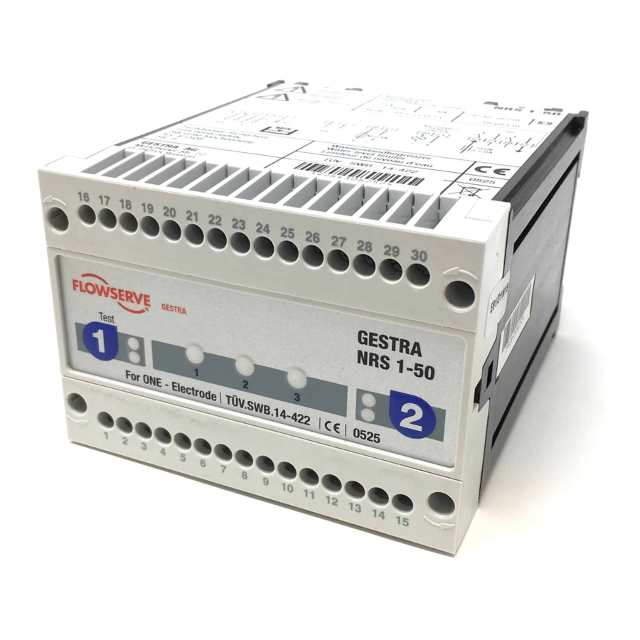
Dimensions and Functional Elements NRS 1-50 16 17 18 19 20 21 22 23 24 25 26 28 29 30 Test 9 10 11 12 13 14 15 Fig. 6 Upper terminal strip Lower terminal strip Fixing screws (cross recess head screws M3) -
Page 13: Important Notes
The name plate specifies the technical features of the equipment. Note that any piece of equipment without its specific name plate must neither be commissioned nor operated. Scope of supply NRS 1-50 1 Level switch NRS 1-50 1 Installation manual…
-
Page 14: Installation
Installation Mounting level switch NRS 1-50 The level switch NRS 1-50 is clipped onto the support rail type TH 35, EN 60715 in the control cabinet. Fig. 6 5 Electrical Connection Supply voltage Fuse the level switch NRS 1-50 with an external semi-delay fuse 0.5 A.
-
Page 15: Connection For Signal Output
(terminals 20, 21) opens instantaneously. Danger For the supply of the level switch NRS 1-50 with 24 V DC use a safety extra-low volt- age (SELV) power supply unit that must be electrically isolated from dangerous contact voltages and must meet at least the requirements on double or reinforced isolation acc.
-
Page 16: Wiring Diagram For Level Switch Nrs 1-50
M 0,5A 17 18 19 20 21 22 23 24 Test Test 11 12 + – * NRS 1-50 with response sensitivity 0.5 μS: NRG 1..-50 Connect the two internal screens to terminal 5 and NRG 1..-11 the CEP. NRG 16-36 Fig.
-
Page 17: Schematic Representations Of Arrangements
Electrical Connection — continued — Schematic representations of arrangements Fig. 9 Fig. 8 Fig. 10 Fig. 11 Level electrode NRG 1…-50 Safety circuit Level switch NRS 1-50 Level switch NRS 1-50 for low-level pre-alarm…
-
Page 18: Explanatory Notes To Schematic Respresentations
EN 12952-07 / EN 12953-06, 72 h operation Fig. 8 Combination consisting of 1 level electrode NRG 1…-50 and 1 level switch NRS 1-50 as water level limiter. Functional safety IEC 61508, SIL 3. For operation according to TRD 604, EN 12952-07 / EN 12953-06 (72 hours), two independent and separate water level limiters must be used.
-
Page 19: Basic Settings
Basic Settings Factory setting Level Switch NRS 1-50 The level switch features the following factory set default values: De-energizing delay: 3 sec., 15 sec. for marine applications. Commissioning Procedure Danger The terminal strips of the equipment are live during operation.
-
Page 20: Checking Switchpoint And Function
Commissioning — continued — Checking switchpoint and function Test Test Level electrode Test & diagnosis Test & diagnosis button button LED alarm 1 / operating mode Fig. 12 Diagnosis LED Start Activity Indication Function System is being started and tested, this takes approx.
-
Page 21: Operation, Alarm And Test
Operation, Alarm and Test Indicators and adjustors Test Test Level electrode Test & diagnosis Test & diagnosis button button LED alarm 1 / operating mode Fig. 12 Diagnosis LED Operation Activity Indication Function Green LED Output contacts are closed. Level electrode submerged. for level electrode is illuminated Signal output opens.
-
Page 22
Troubleshooting — continued — Indication, diagnosis and remedy — continued — Fault indication Status Diagnosis Function Next activity Output contacts are opened Faulty evaluation of level Diagnosis LED 1 and instantaneously. next: Press key 1. electrode, channel 1 LED alarm 1 illuminated. Signal output closes instantaneously. -
Page 23: Checking Level Electrode
Stand-by input 1, 24 V DC, for connecting the logic unit SRL Level electrode NRG 1…-50, NRG 1…-11, NRG 16-36 CEP Central earthing point in control cabinet Note The self-checking routine of the level switch NRS 1-50 reduces U to 0 Volt, if executed cyclically.
-
Page 24: Further Notes
HF interference suppression by means of hinged-shell ferrite rings. Interlock and interlock deactivation In the event of an alarm the level switch NRS 1-50 does not interlock automatically. If a lock function is required by the installation it must be provided in the follow-up circuitry (safety circuit).
-
Page 25
For your notes… -
Page 26
For your notes… -
Page 27
For your notes… -
Page 28
Agencies all over the world: www.gestra.de GESTRA AG Münchener Straße 77 28215 Bremen Germany Telefon +49 421 3503-0 Telefax +49 421 3503-393 E-mail info@de.gestra.com www.gestra.de 818987-05/04-2017csa (808835-05) · GESTRA AG · Bremen · Printed in Germany…

-
Bookmarks
Quick Links
E N
E n g l i s h
Level Switch
NRS 1-50
For TWO Electrodes
Original Installation Instructions
818953-08
Related Manuals for GESTRA NRS 1-50
Summary of Contents for GESTRA NRS 1-50
-
Page 1
Level Switch NRS 1-50 For TWO Electrodes Original Installation Instructions 818953-08 E n g l i s h… -
Page 2
Scope of supply ……………………….5 Potentially explosive areas ……………………5 Functional Safety acc. to IEC 61508 Safety characteristics of the subsystem NRG 1…-50 / NRS 1-50 ………….6 Terms and abbreviations …………………….6 Determination of the Safety Integrity Level (SIL) for safety-related systems ……….7 Technical Data NRS 1-50 …………………………8… -
Page 3
Action against high frequency interference ………………..23 Interlock and interlock deactivation …………………..23 Checking the switchpoints ……………………23 Decommissioning / replacing level switch …………………23 Disposal …………………………23 Declaration of Conformity Directives and Standards ……………………24 NRS 1-50 For TWO Electrodes — Installation Instructions — 818953-08… -
Page 4
Important Notes Usage for the intended purpose The level switch NRS 1-50 is used in conjunction with level electrodes NRG 1…-.. to limit the water level in steam boilers and (pressurised) hot-water plants. Water level limiters switch off the heating when the water level falls below the set minimum level (low water). -
Page 5
1 Level switch NRS 1-50 1 Installation manual Potentially explosive areas The level switch NRS 1-50 must not be used in potentially explosive areas. Note The level electrodes NRG 1…-50, NRG 1…-11 and NRG 16-36 are simple items of electrical equipment as specified in EN 60079-11 section 5.7. -
Page 6
Functional Safety acc. to IEC 61508 Safety characteristics of the subsystem NRG 1…-50 / NRS 1-50 The level switch NRS 1-50 is certified acc. to IEC 61508 if used in combination with level electrode NRG 1…-50 / NRG 16-36 . -
Page 7
SIL 3 60 % — < 90 % SIL 2 SIL 3 SIL 4 90 % — < 99 % SIL 3 SIL 4 SIL 4 ≥ 99 % Fig. 4 NRS 1-50 For TWO Electrodes — Installation Instructions — 818953-08… -
Page 8
Electrical safety Degree of contamination: 2, overvoltage category III to EN 61010-01. Protection Housing: IP 40 to EN 60529 Terminal strip: IP 20 to EN 60529 Weight approx. 0.5 kg NRS 1-50 For TWO Electrodes — Installation Instructions — 818953-08… -
Page 9
–20 … +70 °C, defrosting time of the de-energized equipment before it can be put into operation: 24 hours. Relative humidity max. 95 %, no moisture condensation Site altitude max. 2000 m NRS 1-50 For TWO Electrodes — Installation Instructions — 818953-08… -
Page 10
9 Wiring diagram 0 Type approval no. a Material number, serial number b Manufacturer c Type approval d Disposal note The manufacturing date is shown at the side of the equipment. NRS 1-50 For TWO Electrodes — Installation Instructions — 818953-08… -
Page 11
Fixing screws (cross recess head screws M3) Code switch for switching on/off level electrode 1 / 2 Code switch for switching on/off level electrode 1 / 2 Enclosure Supporting rail type TH 35, EN 60715 NRS 1-50 For TWO Electrodes — Installation Instructions — 818953-08… -
Page 12
Provide the output contacts with a 2 A or 1 A (for 72 hours operation) slow-blow fuse. Note In the event of an alarm the level switch NRS 1-50 does not interlock automatically. If a lock function is required by the installation it must be provided in the follow-up circuitry (safety circuit). -
Page 13
(terminals 20, 21 and 29, 30) open instantaneously. Danger For the supply of the level switch NRS 1-50 with 24 V DC use a safety extra-low voltage (SELV) power supply unit that must be electrically isolated from dangerous contact voltages and must meet at least the requirements on double or reinforced isolation acc. -
Page 14
Stand-by input 1 / 2, 24 V DC, for connecting the logic unit SRL 6-50 Level electrode NRG 1…-50, NRG 1…-11 or NRG 16-36 CEP Central earthing point in control cabinet NRS 1-50 For TWO Electrodes — Installation Instructions — 818953-08… -
Page 15
Schematic representations of arrangements Fig. 8 Fig. 9 Fig. 10 Fig. 11 Fig. 12 Fig. 13 Safety circuit Level electrode(s) NRG 1…-50 Level switch NRS 1-50 for low-level pre-alarm Level switch NRS 1-50 NRS 1-50 For TWO Electrodes — Installation Instructions — 818953-08… -
Page 16
Combination consisting of 1 level electrode NRG 1…-50 and 1 level switch NRS 1-50 as water level limiter and 1 level electrode NRG 1…-50 / 1 level switch NRS 1-50 as first low-level alarm. Functional safety IEC 61508, SIL 3. -
Page 17
OFF. Commissioning Procedure Danger The terminal strips of the NRS 1-50 are live during operation. This presents the danger of electric shock! Always cut off power supply to the equipment before mounting, removing or connecting the terminal strips! Changing configuration If only one electrode is used for operation (e. -
Page 18
0.5 μS/cm. Check installation of level electrode. Make sure Upper vent hole flooded. that the level in the protection tube corresponds to the actual water level. NRS 1-50 For TWO Electrodes — Installation Instructions — 818953-08… -
Page 19
Is the wiring in accordance with the wiring diagram and the relevant schematic representation of arrangement? Configuration: Are the code switch settings correct for the number of level electrodes used? NRS 1-50 For TWO Electrodes — Installation Instructions — 818953-08… -
Page 20
Once the fault is eliminated, the level switch returns to normal operation. After elimination of the fault switch off the mains voltage and switch it on again after approx. 5 sec. NRS 1-50 For TWO Electrodes — Installation Instructions — 818953-08… -
Page 21
Stand-by input 1 / 2, 24 V DC, for connecting the logic unit SRL Level electrode NRG 1…-50, NRG 1…-11, NRG 16-36 CEP Central earthing point in control cabinet Note The self-checking routine of the level switch NRS 1-50 reduces U to 0 Volt, 2-4/10-12 if executed cyclically. -
Page 22
Emergency operation Emergency operation for water level limiter If the level switch NRS 1-50 works with two level electrodes NRG 1…-50 (water level limiter to TRD 604, EN 12952-07, EN 12953-06), the installation can continue operating in emergency operation mode according to TRD 401 and EN 12952 and EN 12953 under constant supervision with only 1 level electrode, in case that one of the two installed level electrodes fails. -
Page 23
HF interference suppression by means of hinged-shell ferrite rings. Interlock and interlock deactivation In the event of an alarm the level switch NRS 1-50 does not interlock automatically. If a lock function is required by the installation it must be provided in the follow-up circuitry (safety circuit). -
Page 24
For more information on the conformity of the equipment as well as applied Directives and Standards please refer to our Declaration of Conformity and associated certificates and/or approvals. The Declaration of Conformity can be found online at www.gestra.com and associated certificates can be requested from: GESTRA AG Münchener Straße 77… -
Page 25
For your notes NRS 1-50 For TWO Electrodes — Installation Instructions — 818953-08… -
Page 26
For your notes NRS 1-50 For TWO Electrodes — Installation Instructions — 818953-08… -
Page 27
For your notes NRS 1-50 For TWO Electrodes — Installation Instructions — 818953-08… -
Page 28
GESTRA UK Ltd Germany Telefon +49 421 3503-0 Unit 1 Sopwith Park, Royce Close, Telefax +49 421 3503-393 West Portway Business Park, Andover, E-mail info@de.gestra.com Hampshire SP10 3TS www.gestra.com United Kingdom 818953-08/07-2022cm[uk] (808805-09) · GESTRA AG · Bremen · Printed in Germany…
|
Detail Specifications: 1431/1431932-nrs_150.pdf file (23 Dec 2022) |
Accompanying Data:
GESTRA NRS 1-50 Switch PDF Installation Instructions Manual (Updated: Friday 23rd of December 2022 05:05:18 PM)
Rating: 4.5 (rated by 100 users)
Compatible devices: TRS 5-52, NRS 1-41, NRS 2-50, LRS 1-50, TRS 5-50, NRS 1-55, TRS 5-8, TRS 5-6.
Recommended Documentation:
Text Version of Installation Instructions Manual
(Ocr-Read Summary of Contents, UPD: 23 December 2022)
-
6, GESTRA NRS 1-50 6 ATEX (Atmosphère Explosible) According to the European Directive 2014/34/EU the level switch NRS 1-50 must not be used in potentially explosive areas. Note The level electrodes NRG 1…-50, NRG 1…-11 and NRG 16-36 are simple items of electri- cal equipment as specified in EN 60079-11 section 5.7. According to the European Direc- tive 2014/34/EU the equipment must be equipped with approved…
-
22, GESTRA NRS 1-50 22 Troubleshooting — continued — Diagnosis Display 1 and activity Display 2 Fault Remedy LED alarm 1 and diagnosis LED 1 illuminated. Press and hold down key 1. Diagnosis LED 1 flashing. Malfunction in level elec- trode, malfunction in level switch, faulty wiring, faulty measuring voltage. — check wiring, — measure electrode voltages, — clean and, if…
-
17, 17 d e f Fig. 8 d e f Fig. 9 Electrical Connection — continued — Schematic representations of arrangements d d g e ff Fig. 10 Fig. 11 e e d Level electrode NRG 1…-50 e Level switch NRS 1-50 Key f Safety circuit g Level switch NRS 1-50 for low-level pre-alarm
… -
3, 3 Contents — continued — Checking switchpoint and function ………………………………………………………………………………………….20 Commissioning Procedure Page Indicators and adjustors …………………………………………………………………………………………………………21 Operation, Alarm and Test Ind…
-
7, 7 Functional Safety acc. to IEC 61508 Safety characteristics of the subsystem NRG 1…-50 / NRS 1-50 The level switch NRS 1-50 is certified acc. to IEC 61508 if used in combination with level electrode NRG 1…-50 / NRG 16-36. The combination NRG 1…-50 / NRG 16-36 / NRS 1-50 corresponds to a type B subsystem with Safety Integrity Level (SIL) 3. Type B means that…
-
5, 5 Directives and Standards Pressure Equipment Directive (PED) 2014/68/EU Water level limiters are safety accessories as defined in the Pressure Equipment Directive (PED). The level switch NRS 1-50 in conjunction with level electrode NRG 1…-50 and NRG 16-36 is EC type approved according to EN 12952/EN 12953. These Directives state, among other things, the require- ment…
-
4, GESTRA NRS 1-50 4 Application Usage for the intended purpose The level switch NRS 1-50 is used in conjunction with level electrode NRG 1…-.. to limit the water level in steam boilers and (pressurised) hot-water plants. Water level limiters switch off the heating when the water level falls below the set minimum level (low water). Depending on the specified directives or standards, the level switc…
-
8, 8 Functional safety acc. to IEC 61508 — continued — Determination of the Safety Integrity Level (SIL) for safety-related systems Level electrode, level switch and actuators (auxiliary contactor in safety circuit) are subsystems and together constitute a safety-related system that executes a safety function. The specification of the safety-related characteristics Fig. 1 ref…
-
28, 28 818987-05/04-2017csa (808835-05) · GESTRA AG · Bremen · Printed in Germany Agencies all over the world: www.gestra.de GESTRA AG Münchener Straße 77 28215 Bremen Germany Telefon +49 421 3503-0 Telefax +49 421 3503-393 E-mail [email protected] Web www.gestra.de
… -
21, 21 Operation Activity Indication Function Level electrode submerged. Green LED for level electrode is illuminated Output contacts are closed. Signal output opens. Alarm Level electrode exposed, level below low water level (LW). Red LED for level electrode is flashing De-energizing delay is running. Signal output is closed instantaneously. Red LED for level electro…
Recommended Instructions:
X305-Q705, 1625 TempLinc, TS960-4, Starfinder 16, Combolight LV Series AR70 LV, ECR 8100


-
• Verwenden Sie das Produkt niemals gleich dann, wenn es von einem kalten in einen warmen Raum gebracht wird. Das dabei entstehende Kondenswasser kann unter Umständen das Produkt zerstören. Lassen Sie das Produkt zuerst auf Zimmertemperatur kommen, bevor es angeschlossen und verwendet wird. Dies kann u.U. mehrere Stunden dauern.• Wenden Sie sich an eine Fachkraft, wenn Sie Zweifel über …
1897810 4
-
www.becos.ro Disclaimer: Technical knowledge is required for installation of electric devices, electronic circuits and parts. You, the buyer or user, are the only person in charge for solving electrical, mechanical or other technical problems that may arise during installation or usage of our products. We assume no responsibility for the way you use the purchased product and we will not be li …
TS8-MS 6
-
NEC Express Server Express5800 Series Express5800/ A1040b, A2040b, A2020b, A2010b User’s Guide Chapter 1 General Description Chapter 2 Preparations Chapter 3 Setup Chapter 4 Appendix 80.102.01-101.01 February 2014, First Edition © NEC Corporation 2014 …
EXPRESS5800 N8403-019 491
-
лчиттничюнльтцию.глтчн.Бзвыдныwww.sotmarket.ruдбняинфмциятв,тзывы,бзыиыИнструкция для(Установка)TP-Link TL-SG2424П …
TL-SG2216 30
Additional Information:
Popular Right Now:
Operating Impressions, Questions and Answers:
Личный кабинет
Вход Зарегистрироваться
- Мои заказы
- Мой профиль
- О нас
- Доставка и оплата
- Гарантии
- Нас рекомендуют
- Контакты
- Бренды
- Еще
![]()
8 (903) 633-37-02
8 495 646-83-72
8 4712 58-51-58
sales@tehkomsale.ru
0
Корзина пуста
- Главная
- —Реле
Реле давления; Преобразователи; Калибровочный сервисРеле перегрузкиРеле котрольноеРеле давления серии 9012 от Square D. 9012-ACW
- —Реле котрольное
- —Реле контрольное Gestra Level Switch NRS1-50 Flowserve NRS-1-50
Оставить отзыв

| Производитель | Flowserve |
В наличии
94 899,10 ₽
В корзину
ХарактеристикиОтзывы (0)
Характеристики
| Производитель | Flowserve |
Реле контрольное Gestra Level Switch NRS1-50 Flowserve NRS-1-50 отзывы
Написать отзыв
Об этом товаре отзывов пока нет. Будьте первым!

Аккуратно упакуем хрупкие товары

Бесплатная доставка при покупке от 5 000 руб

Более 1 000 пунктов самовывоза по РФ

Весь ассортимент сертифицирован

Подарки при заказе от 3000 рублей

Принимаем все способы оплаты

Принимаем заказы на сайте круглосуточно

Профессиональная помощь в подборе товаров

Скидки постоянным покупателям

Супер срочная доставка в течение 2х часов