- Manuals
- Brands
- Gigabyte Manuals
- Motherboard
- B460M DS3H AC
- User manual
-
Contents
-
Table of Contents
-
Bookmarks
Quick Links
B460M DS3H AC
B460M DS3H
User’s Manual
Rev. 1001
B460M DS3H AC
B460M DS3H
To reduce the impacts on global warming, the packaging materials of this product
are recyclable and reusable. GIGABYTE works with you to protect the environment.
For more product details, please visit GIGABYTE’s website.
Related Manuals for Gigabyte B460M DS3H AC
Summary of Contents for Gigabyte B460M DS3H AC
-
Page 1
Rev. 1001 B460M DS3H AC B460M DS3H For more product details, please visit GIGABYTE’s website. To reduce the impacts on global warming, the packaging materials of this product are recyclable and reusable. GIGABYTE works with you to protect the environment. -
Page 2
The trademarks mentioned in this manual are legally registered to their respective owners. Disclaimer Information in this manual is protected by copyright laws and is the property of GIGABYTE. Changes to the specifications and features in this manual may be made by GIGABYTE without prior notice. -
Page 3: Table Of Contents
Table of Contents B460M DS3H (AC) Motherboard Layout ……………..4 Chapter 1 Hardware Installation ………………5 Installation Precautions ………………5 1-2 Product Specifications ………………6 Installing the CPU ………………..9 Installing the Memory ………………9 Installing an Expansion Card …………….10 Back Panel Connectors ………………10 Internal Connectors……………….
-
Page 4: B460M Ds3H (Ac) Motherboard Layout
COMA F_AUDIO D_LED1 F_USB1 COMB Box Contents 5 B460M DS3H AC or B460M DS3H motherboard 5 Motherboard driver disc 5 Two SATA cables 5 User’s Manual 5 I/O Shield 5 Two antennas * The box contents above are for reference only and the actual items shall depend on the product package you obtain.
-
Page 5: Chapter 1 Hardware Installation
Chapter 1 Hardware Installation Installation Precautions The motherboard contains numerous delicate electronic circuits and components which can become damaged as a result of electrostatic discharge (ESD). Prior to installation, carefully read the user’s manual and follow these procedures: • Prior to installation, make sure the chassis is suitable for the motherboard. •…
-
Page 6: 1-2 Product Specifications
S upport for ECC Un-buffered DIMM 1Rx8/2Rx8 memory modules (operate in Š non-ECC mode) Support for non-ECC Un-buffered DIMM 1Rx8/2Rx8/1Rx16 memory modules Š Support for Extreme Memory Profile (XMP) memory modules Š (Go to GIGABYTE’s website for the latest supported memory speeds and memory modules.) Onboard Integrated Graphics Processor-Intel HD Graphics support: Š ®…
-
Page 7
4 x USB 3.2 Gen 1 ports Š 2 x USB 2.0/1.1 ports Š 1 x RJ-45 port Š 2 x SMA antenna connectors (1T1R) Š 3 x audio jacks Š I/O Controller I/O Controller Chip Š ® Only for the B460M DS3H. Only for the B460M DS3H AC. — 7 -… -
Page 8
Only for the B460M DS3H AC. B460M DS3H AC B460M DS3H Please visit GIGABYTE’s website for support lists of CPU, memory modules, SSDs, and M.2 devices. Please visit the SupportUtility List page on GIGABYTE’s website to download the latest version of apps. — 8 -… -
Page 9: Installing The Cpu
• Make sure that the motherboard supports the memory. It is recommended that memory of the same capacity, brand, speed, and chips be used. (Go to GIGABYTE’s website for the latest supported memory speeds and memory modules.) • Always turn off the computer and unplug the power cord from the power outlet before installing the memory to prevent hardware damage.
-
Page 10: Installing An Expansion Card
(the actual resolutions supported depend on the monitor being used). Connect a monitor that supports DVI-D connection to this port. Only for the B460M DS3H. Only for the B460M DS3H AC. (Note) The DVI-D port does not support D-Sub connection by adapter. • When removing the cable connected to a back panel connector, first remove the cable from your device and then remove it from the motherboard.
-
Page 11
Mic In/Center/Subwoofer Speaker Out (Pink) The Mic in jack. Audio Jack Configurations: Headphone/ Jack 4-channel 5.1-channel 7.1-channel 2-channel Line In/Rear Speaker Out Line Out/Front Speaker Out Mic In/Center/Subwoofer Speaker Out Front Panel Line Out/Side Speaker Out Only for the B460M DS3H. Please visit GIGABYTE’s website for details on configuring the audio software. — 11 -… -
Page 12: Internal Connectors
Internal Connectors ATX_12V_2X4 F_PANEL F_AUDIO CPU_FAN F_U32 SYS_FAN1/2 F_USB1/F_USB2 D_LED1/D_LED2 SPI_TPM LED_C1/LED_C2 COMA/COMB SATA3 0/1/2/3/4/5 M2M_SB CLR_CMOS Only for the B460M DS3H. Read the following guidelines before connecting external devices: • First make sure your devices are compliant with the connectors you wish to connect. • Before installing the devices, be sure to turn off the devices and your computer. Unplug the power cord from the power outlet to prevent damage to the devices.
-
Page 13
1/2) ATX_12V_2X4/ATX (2×4 12V Power Connector and 2×12 Main Power Connector) With the use of the power connector, the power supply can supply enough stable power to all the components on the motherboard. Before connecting the power connector, first make sure the power supply is turned off and all devices are properly installed. The power connector possesses a foolproof design. -
Page 14
LED strip. For how to turn on/off the lights of the LED strip please visit the «Unique Features» webpage of GIGABYTE’s website. Before installing the devices, be sure to turn off the devices and your computer. Unplug the power cord from the power outlet to prevent damage to the devices. -
Page 15
S B_ 7) SATA3 0/1/2/3/4/5 (SATA 6Gb/s Connectors) The SATA connectors conform to SATA 6Gb/s standard and are compatible with SATA 3Gb/s and SATA 1.5Gb/s standard. Each SATA connector supports a single SATA device. The Intel Chipset supports ® RAID 0, RAID 1, RAID 5, and RAID 10. Refer to Chapter 3, «Configuring a RAID Set,» for instructions on configuring a RAID array. -
Page 16
Installation Notices for the M.2 and SATA Connectors: The availability of the SATA connectors may be affected by the type of device installed in the M.2 socket. The M2M_SB connector shares bandwidth with the SATA3 5 connector. Refer to the following tables for details. Connector Type of M.2 SATA3 0 SATA3 1 SATA3 2 SATA3 3 SATA3 4 SATA3 5 M.2 SATA SSD… -
Page 17
9) F_PANEL (Front Panel Header) Connect the power switch, reset switch, speaker, chassis intrusion switch/sensor and system status indicator on the chassis to this header according to the pin assignments below. Note the positive and negative pins before connecting the cables. • PLED/PWR_LED (Power LED): Power LED Power Switch Speaker Connects to the power status indicator System Status LED on the chassis front panel. -
Page 18
F_USB30 F_ U 11) F_U32 (USB 3.2 Gen 1 Header) The header conforms to USB 3.2 Gen 1 and USB 2.0 specification and can provide two USB ports. For purchasing the optional 3.5″ front panel that provides two USB 3.2 Gen 1 ports, please contact the local dealer. Pin No. Definition Pin No. Definition Pin No. Definition VBUS SSTX2- SSRX1- SSRX1+ SSRX2+ B S S SSRX2- SSTX1- VBUS SSTX1+ No Pin B S_ SSTX2+ 12) F_USB1/F_USB2 (USB 2.0/1.1 Headers) S B_ The headers conform to USB 2.0/1.1 specification. Each USB header can provide two USB ports via an optional USB bracket. -
Page 19
14) COMA/COMB (Serial Port Headers) The COM headers can provide one serial port via an optional COM port cable. For purchasing the optional COM port cable, please contact the local dealer. Pin No. Definition Pin No. Definition NDCD- NDSR- NSIN NRTS- NSOUT NCTS- NDTR- NRI-… -
Page 20: Chapter 2 Bios Setup
To access the BIOS Setup program, press the <Delete> key during the POST when the power is turned on. To upgrade the BIOS, use either the GIGABYTE Q-Flash or @BIOS utility. Q-Flash allows the user to quickly and easily upgrade or back up BIOS without entering the operating •…
-
Page 21: The Main Menu
The Main Menu System Setup Menus Time Configuration Items Hardware Information Option Description Current Settings Quick Access Bar allows you to quickly move to the General Help, Easy Mode, Smart Fan 5, or Q-Flash screen. Advanced Mode Function Keys <f><g> Move the selection bar to select a setup menu <h><i>…
-
Page 22: Favorites (F11)
Favorites (F11) Set your frequently used options as your favorites and use the <F11> key to quickly switch to the page where all of your favorite options are located. To add or remove a favorite option, go to its original page and press <Insert> on the option. The option is marked with a star sign if set as a «favorite.»…
-
Page 23: Tweaker
Tweaker Whether the system will work stably with the overclock/overvoltage settings you made is dependent on your overall system configurations. Incorrectly doing overclock/overvoltage may result in damage to CPU, chipset, or memory and reduce the useful life of these components. This page is for advanced users only and we recommend you not to alter the default settings to prevent system instability or other unexpected results.
-
Page 24
& VT-d Enables or disables Intel Virtualization Technology for Directed I/O. (Default: Enabled) ® & Intel(R) Speed Shift Technology (Intel Speed Shift Technology) ® (Note) Enables or disables Intel Speed Shift Technology. Enabling this feature allows the processor to ramp up ® its operating frequency more quickly and then improves the system responsiveness. (Default: Enabled) &… -
Page 25
d C-States Control & CPU Enhanced Halt (C1E) Enables or disables Intel CPU Enhanced Halt (C1E) function, a CPU power-saving function in system ® halt state. When enabled, the CPU core frequency and voltage will be reduced during system halt state to decrease power consumption. -
Page 26
& Core Current Limit (Amps) Allows you to set a current limit for CPU Turbo mode. When the CPU current exceeds the specified current limit, the CPU will automatically reduce the core frequency in order to reduce the current. Auto sets the power limit according to the CPU specifications. This item is configurable only when Turbo Power Limits is set to Enabled. (Default: Auto) d Turbo Per Core Limit Control (Note 1) Allows you to control each CPU core limit separately. -
Page 27
& Memory Enhancement Settings Provides several memory performance enhancement settings: Auto, Relax OC, Enhanced Stability, Normal (basic performance), Enhanced Performance,High Frequency, High Density, and DDR-4500+. (Default: Auto) & Memory Channel Detection Message Allows you to determine whether to show an alert message when the memory is not installed in the optimal memory channel. -
Page 28: Settings
Settings ƒ Platform Power & Platform Power Management Enables or disables the Active State Power Management function (ASPM). (Default: Disabled) & PEG ASPM Allows you to configure the ASPM mode for the device connected to the CPU PEG bus. This item is configurable only when Platform Power Management is set to Enabled. (Default: Disabled) & PCH ASPM Allows you to configure the ASPM mode for the device connected to Chipset’s PCI Express bus. This item is configurable only when Platform Power Management is set to Enabled. (Default: Disabled) &…
-
Page 29
& ErP Determines whether to let the system consume least power in S5 (shutdown) state. (Default: Disabled) Note: When this item is set to Enabled, the following functions will become unavailable: Resume by Alarm, power on by mouse, and power on by keyboard. & Soft-Off by PWR-BTTN Configures the way to turn off the computer in MS-DOS mode using the power button. Press the power button and then the system will be turned off instantly. (Default) Instant-Off Delay 4 Sec. -
Page 30
& Audio Controller Enables or disables the onboard audio function. (Default: Enabled) If you wish to install a 3rd party add-in audio card instead of using the onboard audio, set this item to Disabled. & Above 4G Decoding Enables or disables 64-bit capable devices to be decoded in above 4 GB address space (only if your system supports 64-bit PCI decoding). -
Page 31
ƒ NVMe Configuration Displays information on your M.2 NVME PCIe SSD if installed. ƒ SATA And RST Configuration & SATA Controller(s) Enables or disables the integrated SATA controllers. (Default: Enabled) & SATA Mode Selection Enables or disables RAID for the SATA controllers integrated in the Chipset or configures the SATA controllers to AHCI mode. Enables R AID f or t he S ATA c ontroller. Intel RST Premium With Intel Optane System Acceleration AHCI C onfigures the SATA controllers to AHCI mode. Advanced Host Controller Interface (AHCI) is an interface specification that allows the storage driver to enable advanced Serial ATA features such as Native Command Queuing and hot plug. (Default) &… -
Page 32
& 3DMark01 Enhancement Allows you to determine whether to enhance some legacy benchmark performance. (Default: Disabled) ƒ Trusted Computing Enables or disables Trusted Platform Module (TPM). ƒ PC Health Status & Reset Case Open Status Keeps or clears the record of previous chassis intrusion status. (Default) Disabled Clears the record of previous chassis intrusion status and the Case Open field will Enabled… -
Page 33: System Info
System Info. This section provides information on your motherboard model and BIOS version. You can also select the default language used by the BIOS and manually set the system time. & Access Level Displays the current access level depending on the type of password protection used. (If no password is set, the default will display as Administrator.) The Administrator level allows you to make changes to all BIOS settings;…
-
Page 34: Boot
A password is required for booting the system and for entering the BIOS Setup System program. (Default) & Full Screen LOGO Show Allows you to determine whether to display the GIGABYTE Logo at system startup. Disabled skips the GIGABYTE Logo when the system starts up. (Default: Enabled) & Boot Option Priorities Specifies the overall boot order from the available devices. Removable storage devices that support GPT format will be prefixed with «UEFI:» string on the boot device list. To boot from an operating system that…
-
Page 35
& USB Support Disable Link All USB devices are disabled before the OS boot process completes. Full Initial All USB devices are functional in the operating system and during the POST. (Default) Partial Initial Part of the USB devices are disabled before the OS boot process completes. This item is configurable only when Fast Boot is set to Enabled or Ultra Fast. -
Page 36
& Administrator Password Allows you to configure an administrator password. Press <Enter> on this item, type the password, and then press <Enter>. You will be requested to confirm the password. Type the password again and press <Enter>. You must enter the administrator password (or user password) at system startup and when entering BIOS Setup. Differing from the user password, the administrator password allows you to make changes to all BIOS settings. &… -
Page 37: Save & Exit
Save & Exit & Save & Exit Setup Press <Enter> on this item and select Yes. This saves the changes to the CMOS and exits the BIOS Setup program. Select No or press <Esc> to return to the BIOS Setup Main Menu. &…
-
Page 38: Chapter 3 Appendix
The actual BIOS Setup menu options you will see shall depend on the motherboard you have and the BIOS version. C-1. Using EZ RAID GIGABYTE motherboards provide you with the EZ RAID feature, allowing you to quickly configure a RAID array with simplified steps. Steps: 1. After restarting the computer, enter the BIOS Setup and go to Settings. Press <Enter> on the EZ RAID item. Select the type of hard drives you use for RAID in the Type tab and then press <Enter>.
-
Page 39
5. Enter the array capacity and press <Enter>. Finally press <Enter> on the Create Volume item to begin creating the RAID array. When prompted to confirm whether to create this volume, press <Y> to confirm or <N> to cancel. 6. When completed, you can see detailed information about the RAID array in the DISK/VOLUME INFORMATION section, including the RAID level, stripe block size, array name, and array capacity, etc. To exit the RAID BIOS utility, press <Esc> or select 6. Exit in MAIN MENU. Please visit GIGABYTE’s website for details on configuring a RAID array. — 39 -… -
Page 40: Installing An Intel ® Optane ™ Memory
Install the RAID driver and operating system With the correct BIOS settings, you are ready to install the operating system. Installing the Operating System As some operating systems already include RAID driver, you do not need to install separate RAID driver during the Windows installation process. After the operating system is installed, we recommend that you install all required drivers from the motherboard driver disc using «Xpress Install» to ensure system performance and compatibility. If the operating system to be installed requires that you provide additional SATA RAID driver during the OS installation process, please refer to the steps below:…
-
Page 41
A-2: Installation in Intel RST Premium With Intel Optane System Acceleration mode If the SATA controller has been configured in Intel RST Premium With Intel Optane System Acceleration mode, please follow the steps below: 1. After system restarts, go to the BIOS Setup, make sure CSM Support under the Boot menu is disabled. 2. -
Page 42: Drivers Installation
«Xpress Install» will automatically scan your system and then list all of the drivers that are recommended to install. You can click the Xpress Install button and «Xpress Install» will install all of the selected drivers. Or click the arrow icon to individually install the drivers you need. Please visit GIGABYTE’s website for Please visit GIGABYTE’s website for more software information. more troubleshooting information. — 42 -…
-
Page 43: Regulatory Notices
Supplier’s Declaration of Conformity 47 CFR § 2.1077 Compliance Information Product Name: Motherboard Trade Name: GIGABYTE Model Number: B460M DS3H AC/B460M DS3H Responsible Party – U.S. Contact Information: G.B.T. Inc. Address: 17358 Railroad street, City Of Industry, CA91748 Tel.: 1-626-854-9338 Internet contact information: https://www.gigabyte.com…
-
Page 44
DIBP). The parts and components have been carefully selected to meet 2015/863. El cumplimiento de estas directivas se evalúa mediante las RoHS requirement. Moreover, we at GIGABYTE are continuing our normas europeas armonizadas. efforts to develop products that do not use internationally banned toxic Dichiarazione di conformità… -
Page 45
European Community Directive RED Directive Compliance Statement: This equipment is suitable for home and office use in all the European Community Member States and EFTA Member States. The low band 5.15 -5.35 GHz is for indoor use only for the countries listed in the table below: Wireless module country approvals: Wireless module model name: 3168NGW Wireless module manufacturer: Intel ® Corporation Korea Wireless Statement: 5.15 — 5.35GHz 대역에서의 작동은 실내로。 Japan Wireless Statement: 5.15GHz帯 ~ 5.35GHz帯: 屋内のみの使用。 Taiwan NCC Wireless Statements / 無線設備警告聲明: 低功率電波輻射性電機管理辦法… -
Page 46: Contact Us
Contact Us GIGA-BYTE TECHNOLOGY CO., LTD. Address: No.6, Baoqiang Rd., Xindian Dist., New Taipei City 231, Taiwan TEL: +886-2-8912-4000, FAX: +886-2-8912-4005 Tech. and Non-Tech. Support (Sales/Marketing) : https://esupport.gigabyte.com WEB address (English): https://www.gigabyte.com WEB address (Chinese): https://www.gigabyte.com/tw GIGABYTE eSupport • To submit a technical or non-technical (Sales/Marketing) question, please link to: https://esupport.gigabyte.com — 46 -…
This manual is also suitable for:
B460m ds3h
инструкцияGigabyte B460M DS3H

For more product details, please visit GIGABYTE’s website.
To reduce the impacts on global warming, the packaging materials of this product
are recyclable and reusable. GIGABYTE works with you to protect the environment.
B460M DS3HB460M DS3H AC
B460M DS3H AC
B460M DS3H
User’s Manual
Rev. 1003

For more product details, please visit GIGABYTE’s website.
To reduce the impacts on global warming, the packaging materials of this product
are recyclable and reusable. GIGABYTE works with you to protect the environment.
B460M DS3HB460M DS3H AC
B460M DS3H AC
B460M DS3H
User‘s Manual
Rev. 1001
Copyright
© 2020 GIGA—BYTE TECHNOLOGY CO., LTD. All rights reserved.
The trademarks mentioned in this manual are legally registered to their respective owners.
Disclaimer
Information in this manual is protected by copyright laws and is the property of GIGABYTE.
Changes to the specications and features in this manual may be made by GIGABYTE
without prior notice.
No part of this manual may be reproduced, copied, translated, transmitted, or published in
any form or by any means without GIGABYTE’s prior written permission.
In order to assist in the use of this product, carefully read the User‘s Manual.
For product-related information, check on our website at: https://www.gigabyte.com
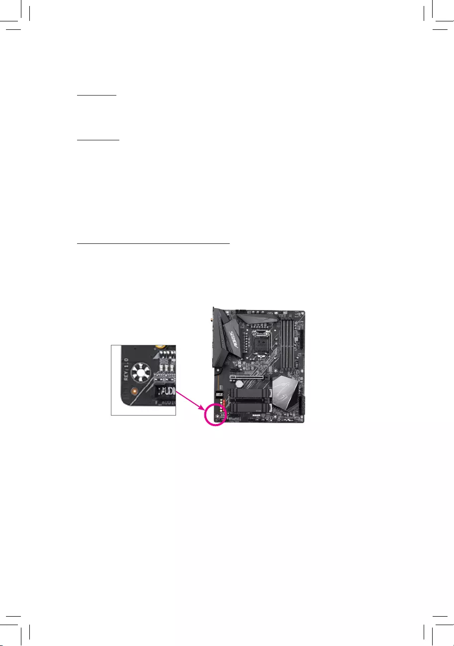
Identifying Your Motherboard Revision
The revision number on your motherboard looks like this: «REV: X.X.» For example, «REV:
1.0» means the revision of the motherboard is 1.0. Check your motherboard revision before
updating motherboard BIOS, drivers, or when looking for technical information.
Example:

— 3 —
Table of Contents
B460M DS3H (AC) Motherboard Layout ……………………………………………………………….4
Chapter 1 Hardware Installation …………………………………………………………………………5
1-1 Installation Precautions …………………………………………………………………………… 5
1-2 ProductSpecications ……………………………………………………………………………. 6
1-3 Installing the CPU ………………………………………………………………………………….. 9
1-4 Installing the Memory ……………………………………………………………………………… 9
1-5 Installing an Expansion Card …………………………………………………………………. 10
1-6 Back Panel Connectors ………………………………………………………………………… 10
1-7 Internal Connectors………………………………………………………………………………. 12
Chapter 2 BIOS Setup …………………………………………………………………………………….20
2-1 Startup Screen …………………………………………………………………………………….. 20
2-2 The Main Menu ……………………………………………………………………………………. 21
2-3 Favorites (F11) …………………………………………………………………………………….. 22
2-4 Tweaker ……………………………………………………………………………………………… 23
2-5 Settings ………………………………………………………………………………………………. 28
2-6 System Info. ………………………………………………………………………………………… 33
2-7 Boot……………………………………………………………………………………………………. 34
2-8 Save & Exit …………………………………………………………………………………………. 37
Chapter 3 Appendix ………………………………………………………………………………………..38
3-1 ConguringaRAIDSet…………………………………………………………………………. 38
3-2 Installing an Intel® Optane™ Memory……………………………………………………….. 40
3-3 Drivers Installation ……………………………………………………………………………….. 42
RegulatoryNotices ………………………………………………………………………………………… 43
Contact Us …………………………………………………………………………………………………… 46
— 4 —
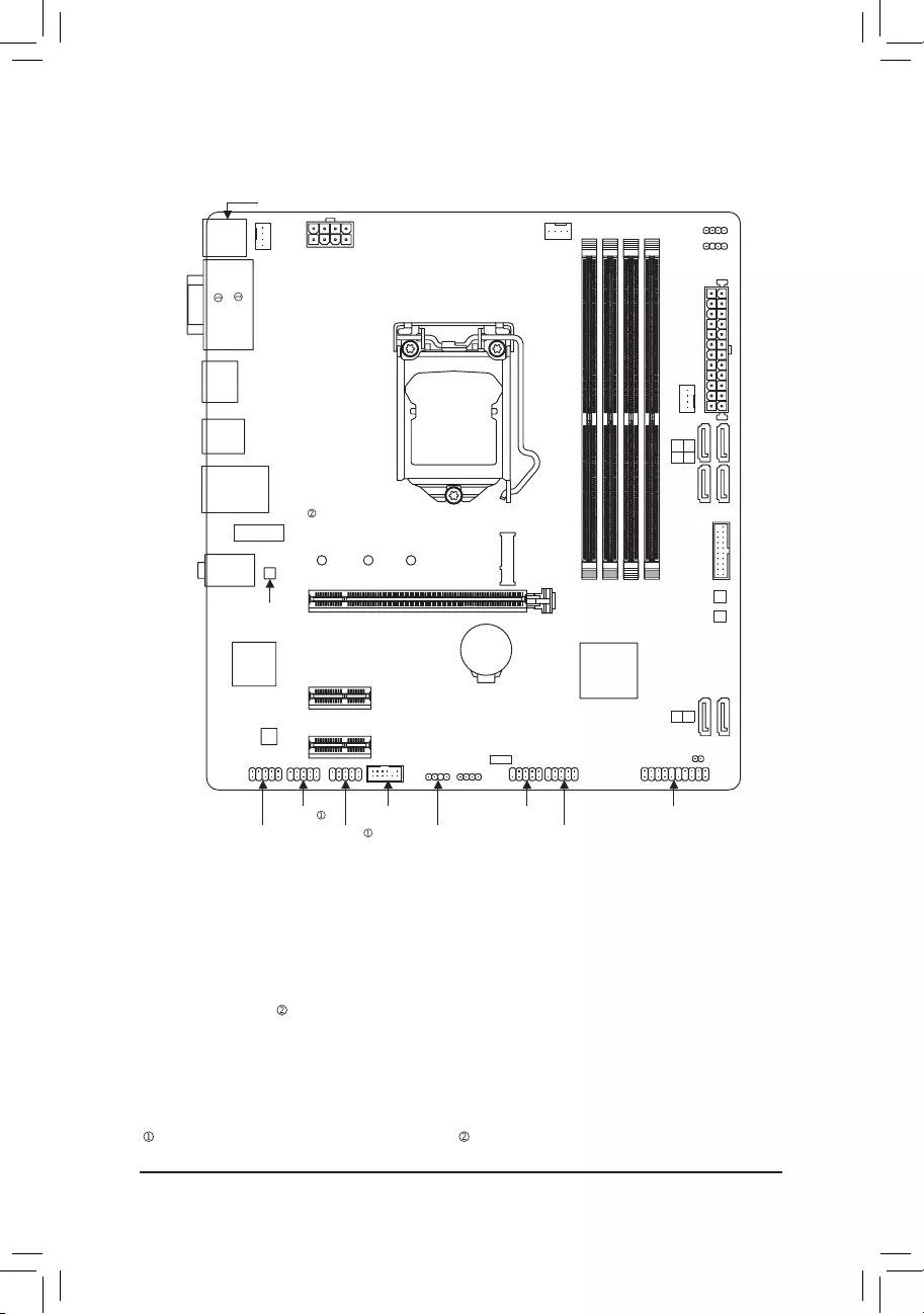
B460M DS3H (AC) Motherboard Layout
* The box contents above are for reference only and the actual items shall depend on the product package you obtain.
The box contents are subject to change without notice.
Box Contents
5B460M DS3H AC or B460M DS3H motherboard
5Motherboard driver disc 5Two SATA cables
5User’s Manual 5I/O Shield
5Two antennas
HDMI
U32_LAN
LGA1200
ATX
AUDIO
ATX_12V_2X4
Intel® B460
CLR_CMOS
M_BIOS
PCIEX1_2
PCIEX16
PCIEX1_1
F_U32
CODEC B460M DS3H (AC)
F_PANEL
F_USB1
LED_C1
F_AUDIO
SPI_TPM
SYS_FAN1
SYS_FAN2
CPU_FAN
iTE®
Super I/O
SATA3 0 1
2 3
BAT
Realtek®
GbELAN
U32
DDR4_B1
DDR4_B2
DDR4_A1
DDR4_A2
D_LED2
LED_C2
COMB D_LED1
M2M_SB
426080
F_USB2
B_BIOS
SATA3 4 5
USB 2.0 Hub
COMA
DVI
M2_WIFI
KB_MS_USB
VGA
Only for the B460M DS3H. Only for the B460M DS3H AC.

Chapter 1 Hardware Installation
1-1 Installation Precautions
The motherboard contains numerous delicate electronic circuits and components which can
become damaged as a result of electrostatic discharge (ESD). Prior to installation, carefully read
the user’s manual and follow these procedures:
•Prior to installation, make sure the chassis is suitable for the motherboard.
•Priortoinstallation,donotremoveorbreakmotherboard S/N(Serial Number)sticker or
warranty sticker provided by your dealer. These stickers are required for warranty validation.
•Always remove the AC power by unplugging the power cord from the power outlet before
installing or removing the motherboard or other hardware components.
•When connecting hardware components to the internal connectors on the motherboard, make
sure they are connected tightly and securely.
•When handling the motherboard, avoid touching any metal leads or connectors.
•It is best to wear an electrostatic discharge (ESD) wrist strap when handling electronic
components such as a motherboard, CPU or memory. If you do not have an ESD wrist strap,
keepyourhandsdryandrsttouchametalobjecttoeliminatestaticelectricity.
•Prior to installing the motherboard, please have it on top of an antistatic pad or within an
electrostatic shielding container.
•Before connecting or unplugging the power supply cable from the motherboard, make sure
the power supply has been turned off.
•Before turning on the power, make sure the power supply voltage has been set according to
the local voltage standard.
•Before using the product, please verify that all cables and power connectors of your hardware
components are connected.
•To prevent damage to the motherboard, do not allow screws to come in contact with the
motherboard circuit or its components.
•Make sure there are no leftover screws or metal components placed on the motherboard or
within the computer casing.
•Do not place the computer system on an uneven surface.
•Do not place the computer system in a high-temperature or wet environment.
•Turning on the computer power during the installation process can lead to damage to system
components as well as physical harm to the user.
•If you are uncertain about any installation steps or have a problem related to the use of the
product,pleaseconsultacertiedcomputertechnician.
•If you use an adapter, extension power cable, or power strip, ensure to consult with its
installation and/or grounding instructions.
— 5 —
1-2 ProductSpecications
CPU Support for 10th Generation Intel® Core™ i9 processors/Intel® Core™ i7 processors/
Intel® Core™ i5 processors/Intel® Core™ i3 processors/Intel® Pentium® processors/
Intel® Celeron® processors in the LGA1200 package
(Go to GIGABYTE’s website for the latest CPU support list.)
L3 cache varies with CPU
Chipset Intel® B460 Express Chipset
Memory Intel® Core™ i9/i7 processors:
- SupportforDDR42933/2666/2400/2133MHz
Intel® Core™ i5/i3/Pentium®/Celeron® processors:
- SupportforDDR42666/2400/2133MHz
4xDDR4DIMMsocketssupportingupto128GB(32GBsingleDIMMcapacity)
of system memory
Dual channel memory architecture
Supportfor ECCUn-buffered DIMM1Rx8/2Rx8 memorymodules(operatein
non-ECC mode)
Supportfornon-ECCUn-bufferedDIMM1Rx8/2Rx8/1Rx16memorymodules
SupportforExtremeMemoryProle(XMP)memorymodules
(Go to GIGABYTE’s website for the latest supported memory speeds and memory
modules.)
Onboard
Graphics
Integrated Graphics Processor-Intel® HD Graphics support:
- 1xD-Subport,supportingamaximumresolutionof1920×1200@60Hz
- 1xDVI-Dport,supportingamaximumresolutionof1920×1200@60Hz
* The DVI-D port does not support D-Sub connection by adapter.
- 1xHDMIport,supportingamaximumresolutionof4096×2160@30Hz
* Support for HDMI 1.4 version and HDCP 2.3.
Support for up to 3 displays at the same time
Maximum shared memory of 512 MB
Audio Realtek® ALC887 codec
HighDenitionAudio
2/4/5.1/7.1-channel
* Tocongure7.1-channelaudio,youneedtoopentheaudiosoftwareandselect
Deviceadvanced settings> PlaybackDevice tochange thedefaultsettingrst.
PleasevisitGIGABYTE’swebsitefordetailsonconguringtheaudiosoftware.
LAN Realtek®GbELANchip(1000 Mbit/100 Mbit)
Wireless
Communication
Module
Intel® Wi—Fi 3168
- Wi—Fi802.11a/b/g/n/ac,supporting2.4/5GHzDual—Band
— BLUETOOTH 4.2
—
Support for 11ac wireless standard and up to 433 Mbps data rate
* Actual data rate may vary depending on environment and equipment.
Expansion Slots 1 x PCI Express x16 slot, running at x16 (PCIEX16)
2 x PCI Express x1 slots
(All of the PCI Express slots conform to PCI Express 3.0 standard.)
— 6 —
Only for the B460M DS3H. Only for the B460M DS3H AC.
Storage Interface 1 x M.2 connector (Socket 3, M key, type 2242/2260/2280 SATA and PCIe x4/
x2 SSD support)
6 x SATA 6Gb/s connectors
SupportforRAID0,RAID1,RAID5,andRAID10
* Referto»1-7InternalConnectors,»fortheinstallationnoticesfortheM.2andSATA
connectors.
Intel® Optane™MemoryReady
USB Chipset:
— 6 x USB 3.2 Gen 1 ports (4 ports on the back panel, 2 ports available through
the internal USB header)
— 2 x USB 2.0/1.1 ports on the back panel
Chipset+USB 2.0 Hub:
— 4 x USB 2.0/1.1 ports available through the internal USB headers
Internal
Connectors
1 x 24-pin ATX main power connector
1 x 8-pin ATX 12V power connector
1 x CPU fan header
2 x system fan headers
2 x addressable LED strip headers
2xRGBLEDstripheaders
6 x SATA 6Gb/s connectors
1 x M.2 Socket 3 connector
1 x front panel header
1 x front panel audio header
1 x USB 3.2 Gen 1 header
2 x USB 2.0/1.1 headers
1 x Trusted Platform Module header (For the GC-TPM2.0 SPI/GC-TPM2.0 SPI
2.0 module only)
2 x serial port headers
1 x Clear CMOS jumper
Back Panel
Connectors
1 x PS/2 keyboard/mouse port
1 x D-Sub port
1 x DVI-D port
1 x HDMI port
4 x USB 3.2 Gen 1 ports
2 x USB 2.0/1.1 ports
1xRJ-45port
2xSMAantennaconnectors(1T1R)
3 x audio jacks
I/O Controller iTE® I/O Controller Chip
— 7 —
Only for the B460M DS3H. Only for the B460M DS3H AC.
Hardware
Monitor
Voltage detection
Temperature detection
Fan speed detection
Overheating warning
Fan fail warning
Fan speed control
* Whether the fan speed control function is supported will depend on the fan you install.
BIOS 2x128Mbitash
Use of licensed AMI UEFI BIOS
Support for DualBIOS™
PnP 1.0a, DMI 2.7, WfM 2.0, SM BIOS 2.7, ACPI 5.0
Unique Features Support for APP Center
* Available applications in APP Center may vary by motherboard model. Supported
functionsofeachapplicationmayalsovarydependingonmotherboardspecications.
— @BIOS
— EasyTune
— Fast Boot
— Game Boost
- ON/OFFCharge
— Ambient LED
- RGBFusion
— Smart Backup
— System Information Viewer
Support for Q-Flash
Support for Xpress Install
Bundled
Software
Norton® Internet Security (OEM version)
Realtek® 8118 Gaming LAN Bandwidth Control Utility
Operating
System Support for Windows 10 64-bit
Form Factor Micro ATX Form Factor; 24.4cm x 22.5cm
* GIGABYTEreservestherighttomakeanychangestotheproductspecicationsandproduct-relatedinformationwithout
prior notice.
Please visit GIGABYTE’s website for support lists of CPU, memory
modules, SSDs, and M.2 devices.
Please visit the SupportUtility List page on GIGABYTE’s website to download the latest
version of apps.
B460M DS3HB460M DS3H AC
Only for the B460M DS3H. Only for the B460M DS3H AC.
— 8 —
1-3 Installing the CPU
ReadthefollowingguidelinesbeforeyoubegintoinstalltheCPU:
•Make sure that the motherboard supports the CPU.
(Go to GIGABYTE‘s website for the latest CPU support list.)
•Always turn off the computer and unplug the power cord from the power outlet before installing
the CPU to prevent hardware damage.
•Locate the pin one of the CPU. The CPU cannot be inserted if oriented incorrectly. (Or you may
locate the notches on both sides of the CPU and alignment keys on the CPU socket.)
•Apply an even and thin layer of thermal grease on the surface of the CPU.
•Do not turn on the computer if the CPU cooler is not installed, otherwise overheating and damage
of the CPU may occur.
•SettheCPUhostfrequencyinaccordancewiththeCPUspecications.Itisnotrecommended
thatthesystembusfrequencybesetbeyondhardwarespecicationssinceitdoesnotmeetthe
standard requirements for the peripherals. If you wish to set the frequency beyond the standard
specications,pleasedosoaccordingtoyourhardwarespecicationsincludingtheCPU,graphics
card, memory, hard drive, etc.
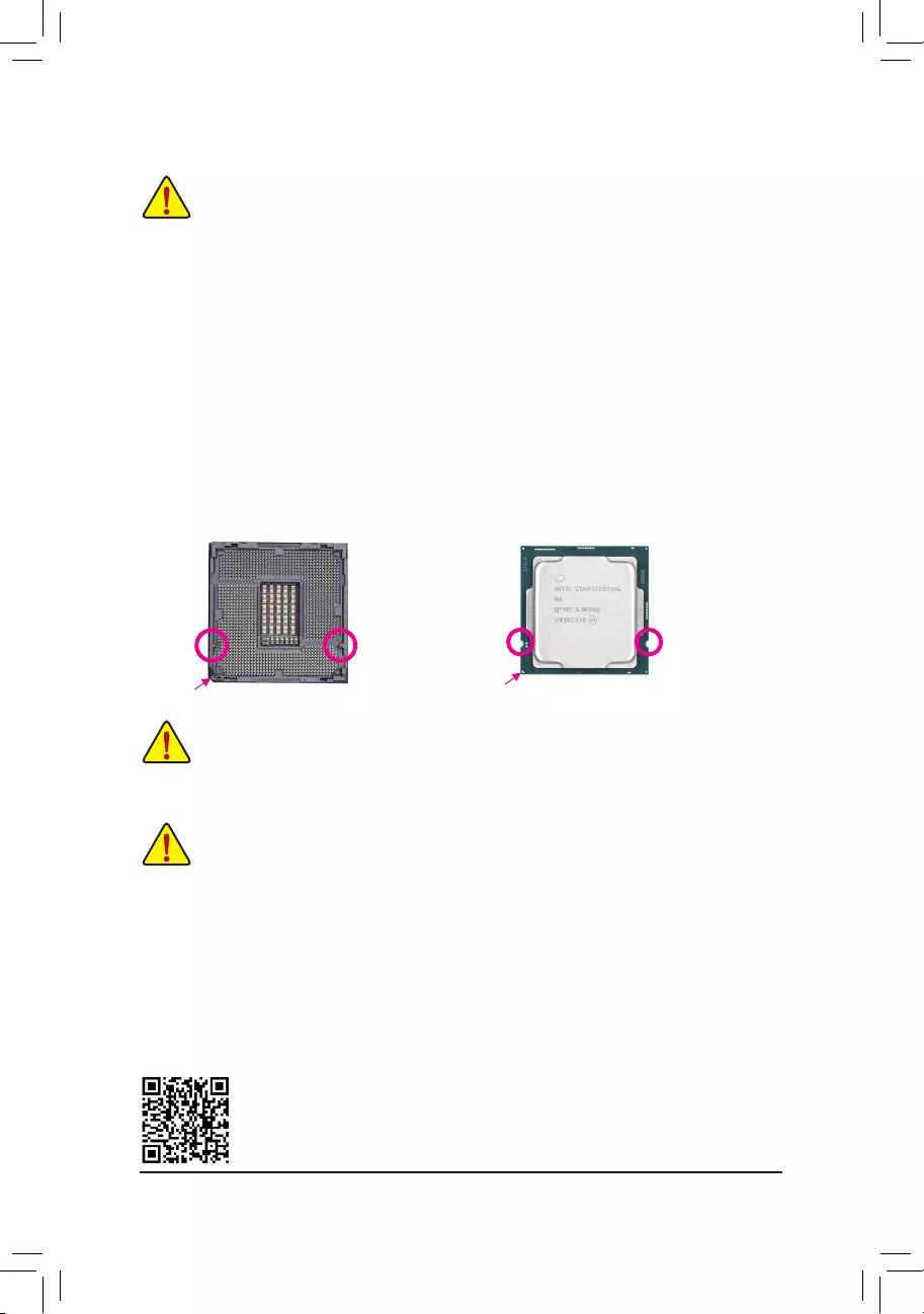
Installing the CPU
Locate the alignment keys on the motherboard CPU socket and the notches on the CPU.
1-4 Installing the Memory
Readthefollowingguidelinesbeforeyoubegintoinstallthememory:
•Make sure that the motherboard supports the memory. It is recommended that memory of the
same capacity, brand, speed, and chips be used.
(Go to GIGABYTE‘s website for the latest supported memory speeds and memory modules.)
•Always turn off the computer and unplug the power cord from the power outlet before installing
the memory to prevent hardware damage.
•Memory modules have a foolproof design. A memory module can be installed in only one direction.
If you are unable to insert the memory, switch the direction.
DualChannelMemoryConguration
This motherboard provides four memory sockets and supports Dual Channel Technology. After the memory
isinstalled,theBIOSwillautomaticallydetectthespecicationsandcapacityofthememory.EnablingDual
Channel memory mode will double the original memory bandwidth.
Please visit GIGABYTE’s website for details on hardware installation.
Do not remove the CPU socket cover before inserting the CPU. It may pop off from the load
plate automatically during the process of re—engaging the lever after you insert the CPU.
Triangle Pin One Marking on the CPU
Notch
Notch
LGA1200 CPU
Alignment
Key
Alignment
Key
LGA1200 CPU Socket
Pin One Corner of the CPU Socket
— 9 —
1-5 Installing an Expansion Card
Readthefollowingguidelinesbeforeyoubegintoinstallanexpansioncard:
•Make sure the motherboard supports the expansion card. Carefully read the manual that came
with your expansion card.
•Always turn off the computer and unplug the power cord from the power outlet before installing
an expansion card to prevent hardware damage.
Due to CPU limitations, read the following guidelines before installing the memory in Dual Channel mode.
1. Dual Channel mode cannot be enabled if only one memory module is installed.
2. When enabling Dual Channel mode with two or four memory modules, it is recommended that
memory of the same capacity, brand, speed, and chips be used.
The four memory sockets are divided into two channels and each channel has two memory sockets as following:
ChannelA:DDR4_A1,DDR4_A2
ChannelB:DDR4_B1,DDR4_B2
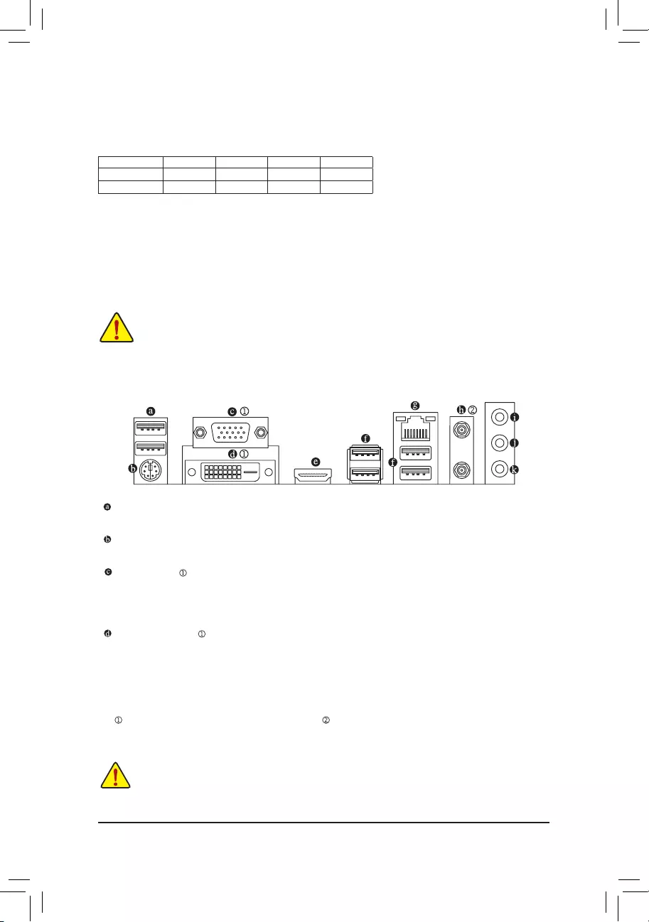
1-6 Back Panel Connectors
USB 2.0/1.1 Port
TheUSBportsupportstheUSB2.0/1.1specication.UsethisportforUSBdevices.
PS/2 Keyboard/Mouse Port
Use this port to connect a PS/2 mouse or keyboard.
D—Sub Port
TheD —Subportsupportsa15—pinD —Subconnectorandsupportsamaximumresolutionof1920x1200@60Hz
(the actual resolutions supported depend on the monitor being used). Connect a monitor that supports
D—Sub connection to this port.
DVI—D Port (Note)
TheDVI—Dpor tconformstotheDVI —Dspecicationandsupportsamaximumresolutionof1920x1200@60Hz
(the actual resolutions supported depend on the monitor being used). Connect a monitor that supports
DVI—D connection to this port.
RecommandedDualChannelMemoryConguration:
DDR4_A1 DDR4_A2 DDR4_B1 DDR4_B2
2 Modules — — DS/SS — — DS/SS
4 Modules DS/SS DS/SS DS/SS DS/SS
(SS=Single-Sided,DS=Double-Sided,»--«=NoMemory)
(Note) TheDVI—DportdoesnotsupportD—Subconnectionbyadapter.
•Whenremovingthecableconnectedtoabackpanelconnector,rstremovethecablefromyour
device and then remove it from the motherboard.
•When removing the cable, pull it straight out from the connector. Do not rock it side to side to
prevent an electrical short inside the cable connector.
— 10 —
Only for the B460M DS3H. Only for the B460M DS3H AC.
USB 3.2 Gen 1 Port
TheUSB3.2Gen1portsupportstheUSB3.2Gen1specicationandiscompatibletotheUSB2.0
specication. Use this port for USB devices.
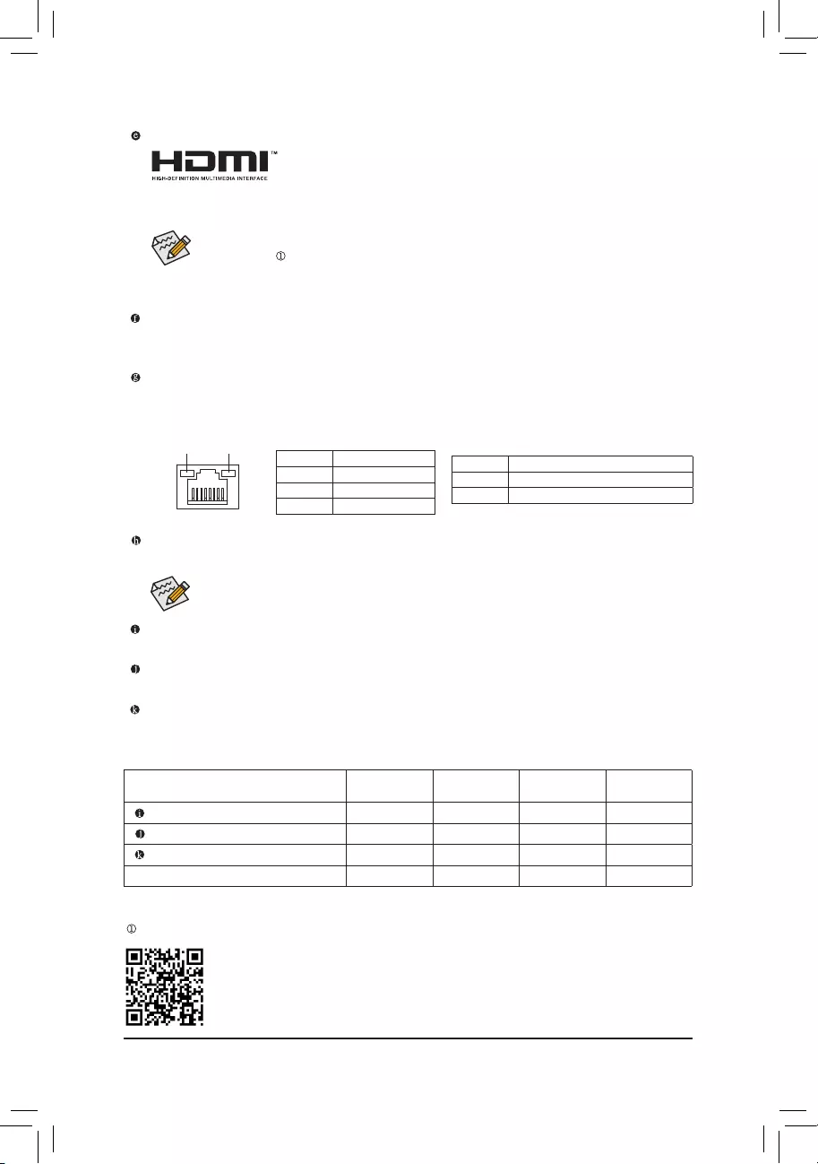
RJ—45 LAN Port
TheGigabitEthernetLANportprovidesInternetconnectionatupto1Gbpsdatarate.Thefollowing
describesthestatesoftheLANportLEDs.
•Tosetupatriple—displayconguration,youmustinstallmotherboarddriversintheoperating
systemrst.
•After installing the HDMI device, make sure to set the default sound playback device to HDMI.
(The item name may differ depending on your operating system.)
HDMI Port
The HDMI port supports HDCP 2.3 and Dolby TrueHD and DTS HD Master
Audioformats.Italsosupportsupto192KHz/16bit7.1-channelLPCMaudio
output. You can use this port to connect your HDMI-supported monitor. The maximum supported resolution
is4096x2160@30Hz,buttheactualresolutionssupportedaredependentonthemonitorbeingused.
SMA Antenna Connectors (1T1R)
Use this connector to connect an antenna.
Activity LED
Connection/
Speed LED
LANPort
Activity LED:
Connection/Speed LED:
State Description
Orange 1 Gbps data rate
Green 100 Mbps data rate
Off 10 Mbps data rate
State Description
Blinking Data transmission or receiving is occurring
Off Nodatatransmissionorreceivingisoccurring
Tighten the antennas to the antenna connectors and then aim the antennas correctly for better
signal reception.
Line In/Rear Speaker Out (Blue)
The line in jack. Use this audio jack for line in devices such as an optical drive, walkman, etc.
Line Out/Front Speaker Out (Green)
The line out jack.
Mic In/Center/Subwoofer Speaker Out (Pink)
The Mic in jack.
AudioJackCongurations:
Jack Headphone/
2-channel 4-channel 5.1-channel 7.1-channel
LineIn/RearSpeakerOut a a a
Line Out/Front Speaker Out a a a a
Mic In/Center/Subwoofer Speaker Out a a
Front Panel Line Out/Side Speaker Out a
PleasevisitGIGABYTE’swebsitefordetailsonconguringtheaudiosoftware.
— 11 —
Only for the B460M DS3H.
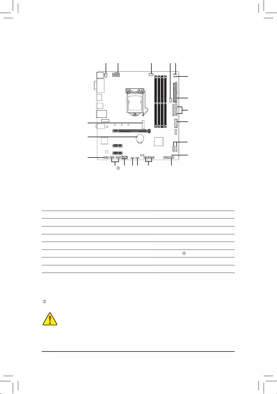
1-7 Internal Connectors
Readthefollowingguidelinesbeforeconnectingexternaldevices:
•First make sure your devices are compliant with the connectors you wish to connect.
•Before installing the devices, be sure to turn off the devices and your computer. Unplug the power
cord from the power outlet to prevent damage to the devices.
•After installing the device and before turning on the computer, make sure the device cable has
been securely attached to the connector on the motherboard.
1) ATX_12V_2X4
2) ATX
3) CPU_FAN
4) SYS_FAN1/2
5) D_LED1/D_LED2
6) LED_C1/LED_C2
7) SATA3 0/1/2/3/4/5
 M2M_SB
9) F_PANEL
10) F_ AUDIO
11) F_U32
12) F_USB1/F_USB2
13) SPI_TPM
14) COMA/COMB
15) BAT
16) CLR_CMOS
9
2
7
11
5
14
13
16
15
14 12
3
10
5
6
6
8
4
7
— 12 —
Only for the B460M DS3H.
131
2412
ATX
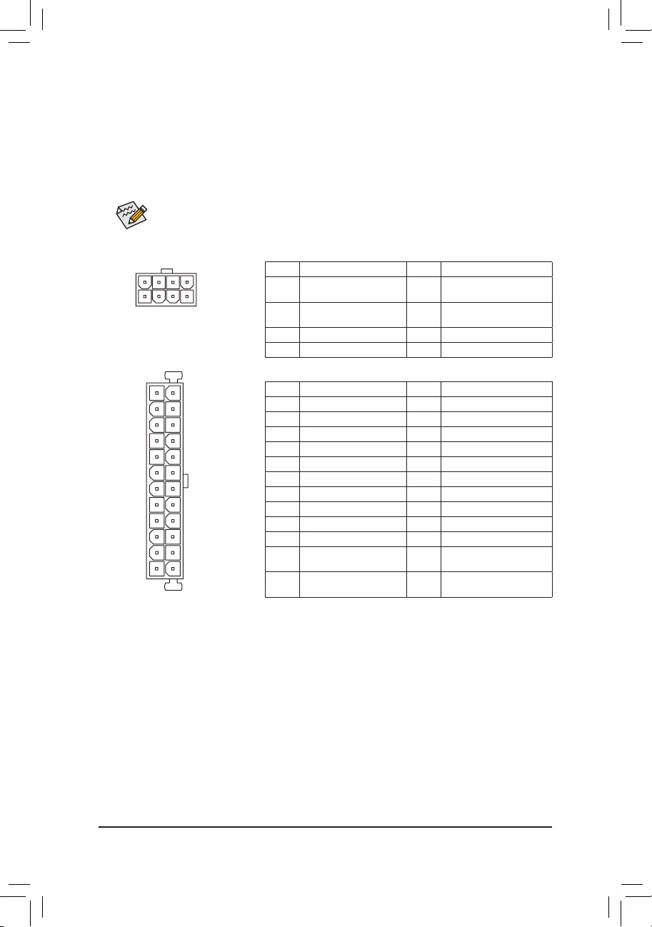
1/2) ATX_12V_2X4/ATX (2x4 12V Power Connector and 2x12 Main Power Connector)
With the use of the power connector, the power supply can supply enough stable power to all the
componentsonthemotherboard.Beforeconnectingthepowerconnector,rstmakesurethepower
supply is turned off and all devices are properly installed. The power connector possesses a foolproof
design. Connect the power supply cable to the power connector in the correct orientation.
The 12V power connector mainly supplies power to the CPU. If the 12V power connector is not connected,
the computer will not start.
To meet expansion requirements, it is recommended that a power supply that can withstand high
power consumption be used (500W or greater). If a power supply is used that does not provide
the required power, the result can lead to an unstable or unbootable system.
ATX:
PinNo. Denition PinNo. Denition
1 3.3V 13 3.3V
2 3.3V 14 -12V
3GND 15 GND
4 +5V 16 PS_ON(softOn/Off)
5GND 17 GND
6 +5V 18 GND
7GND 19 GND
8 Power Good 20 NC
9 5VSB (stand by +5V) 21 +5V
10 +12V 22 +5V
11 +12V (Only for 2×12-pin
ATX)
23 +5V (Only for 2×12-pin ATX)
12 3.3V (Only for 2×12-pin
ATX)
24 GND(Onlyfor2×12-pin
ATX)
ATX_12V_2X4:
PinNo. Denition PinNo. Denition
1GND(Onlyfor2×4-pin
12V)
5 +12V (Only for 2×4-pin 12V)
2GND(Onlyfor2×4-pin
12V)
6 +12V (Only for 2×4-pin 12V)
3GND 7 +12V
4GND 8 +12V
ATX_12V_2X4
41
85
— 13 —
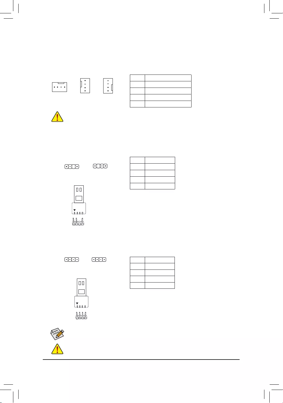
6) LED_C1/LED_C2 (RGB LED Strip Headers)
Theheaderscanbeusedtoconnectastandard5050RGBLEDstrip(12V/G/R/B),withmaximumpower
rating of 2A (12V) and maximum length of 2m.
PinNo. Denition
1 12V
2 G
3R
4 B
ConnectyourRGBLEDstriptotheheader.Thepowerpin
(marked with a triangle on the plug) of the LED strip must be
connected to Pin 1 (12V) of this header. Incorrect connection
may lead to the damage of the LED strip.
RGBLEDStrip
1
12V
5) D_LED1/D_LED2 (Addressable LED Strip Headers)
The headers can be used to connect a standard 5050 addressable LED strip, with maximum power rating
of 5A (5V) and maximum number of 1000 LEDs.
PinNo. Denition
1 V (5V)
2 Data
3NoPin
4GND
Before installing the devices, be sure to turn off the devices and your computer. Unplug the power
cord from the power outlet to prevent damage to the devices.
Forhowtoturnon/offthelightsoftheLEDstrippleasevisitthe»UniqueFeatures«webpageof
GIGABYTE’s website.
Connect your addressable LED strip to the header. The power
pin (marked with a triangle on the plug) of the LED strip must
be connected to Pin 1 of the addressable LED strip header.
Incorrect connection may lead to the damage of the LED strip.
Addressable LED
Strip
1
3/4) CPU_FAN/SYS_FAN1/2 (Fan Headers)
All fan headers on this motherboard are 4—pin. Most fan headers possess a foolproof insertion design.
When connecting a fan cable, be sure to connect it in the correct orientation (the black connector wire
is the ground wire). The speed control function requires the use of a fan with fan speed control design.
For optimum heat dissipation, it is recommended that a system fan be installed inside the chassis.
PinNo. Denition
1GND
2 Voltage Speed Control
3 Sense
4 PWM Speed Control
•Be sure to connect fan cables to the fan headers to prevent your CPU and system from
overheating. Overheating may result in damage to the CPU or the system may hang.
•Thesefanheadersarenotcongurationjumperblocks.Donotplaceajumpercaponthe
headers.
CPU_FAN
1
SYS_FAN2
1
SYS_FAN1
1
1
F_USB30 F_U
B_
F_ F_
_
B
BS_
B
SB_
B
_S
S_
_
B
_U
_
B
S
123
123
123
123
1
1
1
1
BSS
S
_S
SSU
1 2 3 4 5
S3 BSSS
U
__ 3
F_USB3F
S _
S _
S _
SF
B_
B_
F
_0
S
S
_0F
_F
_
_
__B
U
S _S
_ SF_
B
USB0_B
B_
B_
F_USB3
F_USB303
_
_3U
S_
F_USB30 F_U
B_
F_ F_
_
B
BS_
B
SB_
B
_S
S_
_
B
_U
_
B
S
123
123
123
123
1
1
1
1
BSS
S
_S
SSU
1 2 3 4 5
S3 BSSS
U
__ 3
F_USB3F
S _
S _
S _
SF
B_
B_
F
_0
S
S
_0F
_F
_
_
__B
U
S _S
_ SF_
B
USB0_B
B_
B_
F_USB3
F_USB303
_
_3U
S_
D_LED1 D_LED2
1
1
LED_C2
1
LED_C1
— 14 —
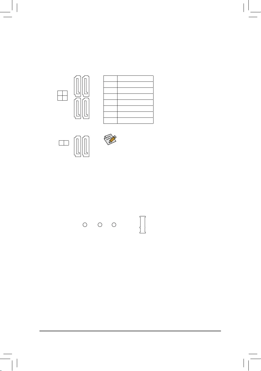
7) SATA3 0/1/2/3/4/5 (SATA 6Gb/s Connectors)
The SATA connectors conform to SATA 6Gb/s standard and are compatible with SATA 3Gb/s and SATA
1.5Gb/s standard. Each SATA connector supports a single SATA device. The Intel® Chipset supports
RAID0,RAID1,RAID5,andRAID10.RefertoChapter3,»ConguringaRAIDSet,»forinstructions
onconguringaRAIDarray.
PinNo. Denition
1GND
2 TXP
3TXN
4GND
5RXN
6RXP
7GND
To enable hot-plugging for the SATA ports, refer to Chapter 2,
«BIOSSetup,«»Set tingsIOPortsSATAAndRSTConguration,«
for more information.
M2M_SB (M.2 Socket 3 Connector)
TheM.2connectorsupportsM.2SATASSDsorM.2PCIeSSDsandsuppor tR AIDconguration.Please
notethatanM.2PCIeSSDcannotbeusedtocreateaRAIDseteitherwithanM.2SATASSDoraSATA
harddrive.TocreateaRAIDarraywithanM.2PCIeSSD,youmustsetupthecongurationinUEFI
BIOSmode.RefertoChapter3,»ConguringaRAIDSet,»forinstructionsonconguringaRAIDarray.
Follow the steps below to correctly install an M.2 SSD in the M.2 connector.
Step 1:
Use a screw driver to unfasten the screw and standoff from the motherboard. Locate the proper mounting
holefortheM.2SSDtobeinstalledandthenscrewthestandoffrst.
Step 2:
Slide the M.2 SSD into the connector at an angle.
Step 3:
Press the M.2 SSD down and then secure it with the screw.
SATA3
SATA3
1 3
0 2
4 5
7
7
1
1
7
7
1
1
F_USB30 F_U
B_
F_ F_
_
B
BS_
B
SB_
B
_S
S_
_
B
_U
_
B
S
123
123
123
123
1
1
1
1
BSS
S
_S
SSU
1 2 3 4 5
S3 BSSS
U
__ 3
F_USB3F
S _
S _
S _
SF
B_
B_
F
_0
S
S
_0F
_F
_
_
__B
U
S _S
_ SF_
B
USB0_B
B_
B_
F_USB3
F_USB303
_
_3U
S_
80 60 42
— 15 —

Installation Notices for the M.2 and SATA Connectors:
The availability of the SATA connectors may be affected by the type of device installed in the M.2 socket. The
M2M_SBconnectorsharesbandwidthwiththeSATA35connector.Refertothefollowingtablesfordetails.
SATA3 0 SATA3 1 SATA3 2 SATA3 3 SATA3 4 SATA3 5
M.2 SATA SSD aaaaar
M.2 PCIe SSD
aaaaaa
NoM.2SSDInstalled aaaaaa
a: Available, r:Notavailable
Connector
Type of M.2
SSD
— 16 —
The front panel design may differ by chassis. A front panel module mainly consists of power
switch, reset switch, power LED, hard drive activity LED, speaker and etc. When connecting
your chassis front panel module to this header, make sure the wire assignments and the pin
assignments are matched correctly.
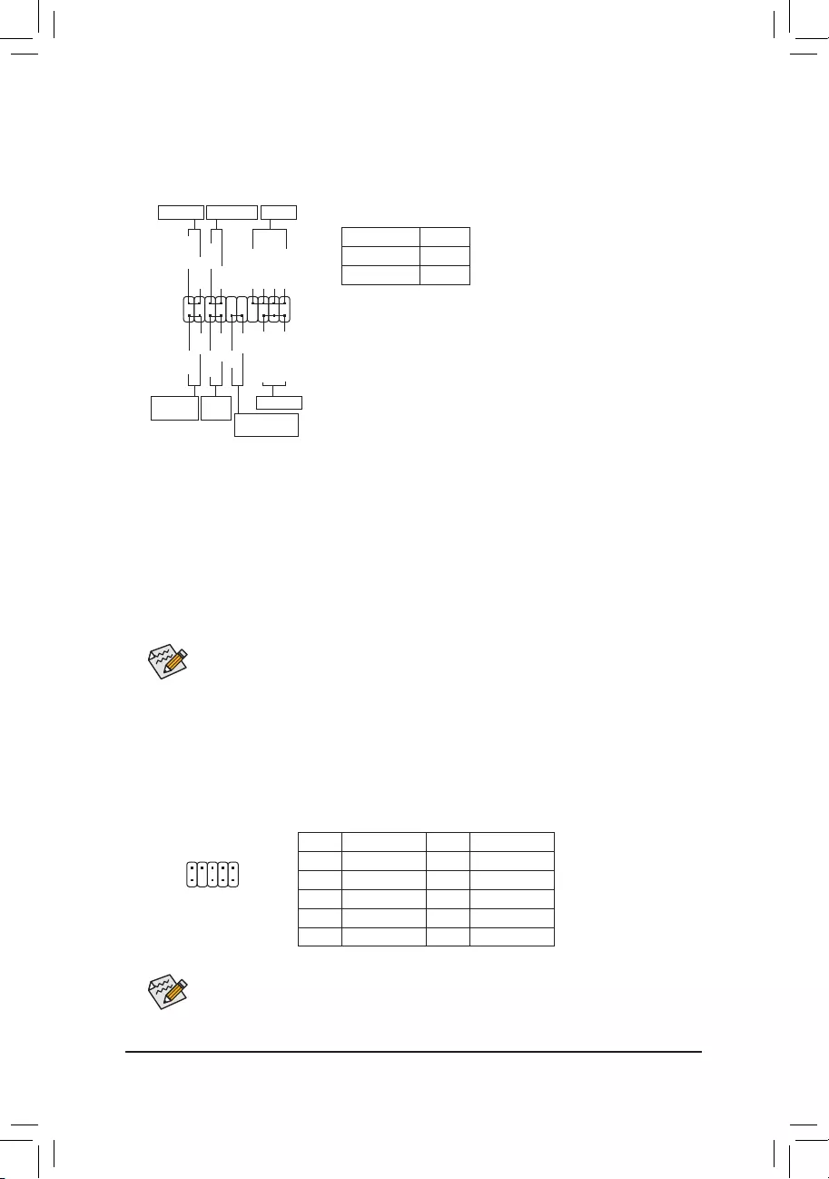
9) F_PANEL (Front Panel Header)
Connect the power switch, reset switch, speaker, chassis intrusion switch/sensor and system status
indicatoronthechassistothisheaderaccordingtothepinassignmentsbelow.Notethepositiveand
negative pins before connecting the cables.
System Status LED
S0 On
S3/S4/S5 Off
•PW (Power Switch):
Connects to the power switch on the chassis front panel. You may
congure the wayto turnoff yoursystemusing thepower switch
(refer to Chapter 2, «BIOS Setup,»«SettingsPlatformPower,«for
more information).
•SPEAK (Speaker):
Connects to the speaker on the chassis front panel. The system
reports system startup status by issuing a beep code. One single
short beep will be heard if no problem is detected at system startup.
•PLED/PWR_LED (Power LED):
Connects to the power status indicator
on the chassis front panel. The LED is on
when the system is operating. The LED is
off when the system is in S3/S4 sleep state
or powered off (S5).
•HD (Hard Drive Activity LED):
Connects to the hard drive activity LED on the chassis front panel. The LED is on when the hard drive
is reading or writing data.
•RES (ResetSwitch):
Connects to the reset switch on the chassis front panel. Press the reset switch to restart the computer
ifthecomputerfreezesandfailstoperformanormalrestart.
•CI (Chassis Intrusion Header):
Connects to the chassis intrusion switch/sensor on the chassis that can detect if the chassis cover
has been removed. This function requires a chassis with a chassis intrusion switch/sensor.
•NC:Noconnection.
10) F_AUDIO (Front Panel Audio Header)
ThefrontpanelaudioheadersupportsHighDenitionaudio(HD).Youmayconnectyourchassisfront
panel audio module to this header. Make sure the wire assignments of the module connector match the
pin assignments of the motherboard header. Incorrect connection between the module connector and
the motherboard header will make the device unable to work or even damage it.
Some chassis provide a front panel audio module that has separated connectors on each wire
instead of a single plug. For information about connecting the front panel audio module that has
different wire assignments, please contact the chassis manufacturer.
PinNo. Denition PinNo. Denition
1 MIC2_L 6 Sense
2GND 7FAUDIO_JD
3MIC2_R 8NoPin
4NC 9LINE2_L
5LINE2_R 10 Sense
Power LED
1
2
19
20
CI-
CI+
PLED-
PW-
SPEAK+
SPEAK-
PLED+
PW+
Power LED
HD-
RES+
HD+
RES-
Hard Drive
Activity LED
Reset
Switch Chassis Intrusion
Header
Power Switch Speaker
F_USB30 F_U
B_
F_ F_
_
B
BS_
B
SB_
B
_S
S_
_
B
_U
_
B
S
123
123
123
123
1
1
1
1
BSS
S
_S
SSU
1 2 3 4 5
S3 BSSS
U
__ 3
F_USB3F
S _
S _
S _
SF
B_
B_
F
_0
S
S
_0F
_F
_
_
__B
U
S _S
_ SF_
USB0_B
B_ F_USB3
F_USB303
_
_3U
PWR_LED-
PWR_LED+
PWR_LED-
NC
NC
1
2
9
10
— 17 —
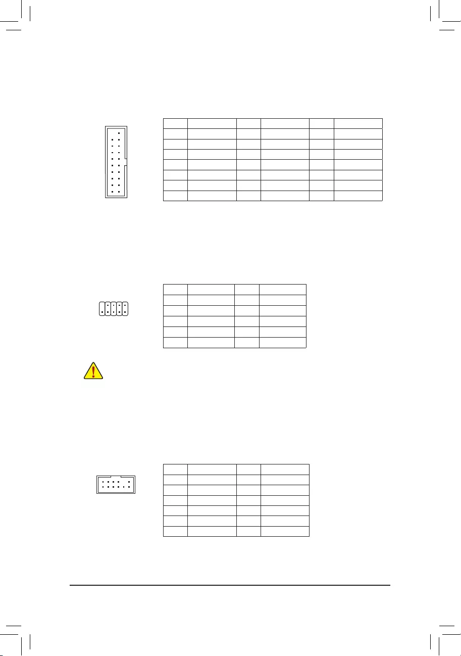
11) F_U32 (USB 3.2 Gen 1 Header)
TheheaderconformstoUSB3.2Gen1andUSB2.0specicationandcanprovidetwoUSBports.For
purchasingtheoptional3.5″frontpanelthatprovidestwoUSB3.2Gen1ports,pleasecontactthelocal
dealer.
F_USB30 F_U
B_
F_ F_
_
B
BS_
B
SB_
B
_S
S_
_
B
_U
_
B
S
123
123
123
123
1
1
1
1
BSS
S
_S
SSU
1 2 3 4 5
S3 BSSS
U
__ 3
F_USB3F
S _
S _
S _
SF
B_
B_
F
_0
S
S
_0F
_F
_
_
__B
U
S _S
_ SF_
B
USB0_B
B_
B_
F_USB3
F_USB303
_
_3U
S_
10
20 1
11
PinNo. Denition PinNo. Denition PinNo. Denition
1 VBUS 8 D1- 15 SSTX2-
2SSRX1- 9 D1+ 16 GND
3SSRX1+ 10 NC 17 SSRX2+
4GND 11 D2+ 18 SSRX2-
5 SSTX1- 12 D2- 19 VBUS
6 SSTX1+ 13 GND 20 NoPin
7GND 14 SSTX2+
12) F_USB1/F_USB2 (USB 2.0/1.1 Headers)
TheheadersconformtoUSB2.0/1.1specication.EachUSBheadercanprovidetwoUSBportsviaan
optional USB bracket. For purchasing the optional USB bracket, please contact the local dealer.
PinNo. Denition PinNo. Denition
1 Power (5V) 6 USB DY+
2 Power (5V) 7 GND
3 USB DX- 8 GND
4 USB DY— 9 NoPin
5 USB DX+ 10 NC
•Do not plug the IEEE 1394 bracket (2x5—pin) cable into the USB 2.0/1.1 header.
•Prior to installing the USB bracket, be sure to turn off your computer and unplug the power
cord from the power outlet to prevent damage to the USB bracket.
10
9 1
2
13) SPI_TPM (Trusted Platform Module Header)
You may connect an SPI TPM (Trusted Platform Module) to this header.
PinNo. Denition PinNo. Denition
1Data Output 7Chip Select
2Power (3.3V) 8GND
3NoPin 9IRQ
4NC 10 NC
5Data Input 11 NC
6CLK 12 RST
12
11
2
1
F_USB30 F_U
B_
F_ F_
_
B
BS_
B
SB_
B
_S
S_
_
B
_U
_
B
S
123
123
123
123
1
1
1
1
BSS
S
_S
SSU
1 2 3 4 5
S3 BSSS
U
__ 3
F_USB3F
S _
S _
S _
SF
B_
B_
F
_0
S
S
_0F
_F
_
_
__B
U
S _S
_ SF_
B
USB0_B
B_
B_
F_USB3
F_USB303
_
_3U
S_
— 18 —
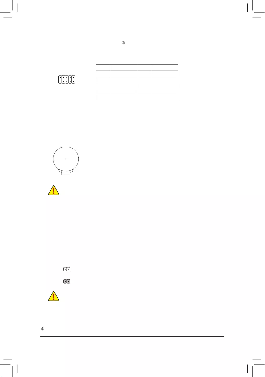
PinNo. Denition PinNo. Denition
1NDCD- 6NDSR-
2NSIN 7NRTS-
3NSOUT 8NCTS-
4NDTR- 9NRI-
5GND 10 NoPin
14) COMA/COMB (Serial Port Headers)
The COM headers can provide one serial port via an optional COM port cable. For purchasing the
optional COM port cable, please contact the local dealer.
10
9
2
1
15) BAT (Battery)
Thebatteryprovidespowertokeepthevalues(suchasBIOScongurations,date,andtimeinformation)
intheCMOSwhenthecomputeristurnedoff.Replacethebatterywhenthebatteryvoltagedropstoa
low level, or the CMOS values may not be accurate or may be lost.
You may clear the CMOS values by removing the battery:
1. Turn off your computer and unplug the power cord.
2. Gently remove the battery from the battery holder and wait for one minute. (Or use
a metal object like a screwdriver to touch the positive and negative terminals of the
battery holder, making them short for 5 seconds.)
3. Replacethebattery.
4. Plug in the power cord and restart your computer.
•Always turn off your computer and unplug the power cord before replacing the battery.
•Replacethebatterywithanequivalentone.Damagetoyourdevicesmayoccurifthebattery
is replaced with an incorrect model.
•Contact the place of purchase or local dealer if you are not able to replace the battery by
yourself or uncertain about the battery model.
•When installing the battery, note the orientation of the positive side (+) and the negative side
(-) of the battery (the positive side should face up).
•Used batteries must be handled in accordance with local environmental regulations.
16) CLR_CMOS (Clear CMOS Jumper)
UsethisjumpertocleartheBIOScongurationandresettheCMOSvaluestofactorydefaults.Toclear
the CMOS values, use a metal object like a screwdriver to touch the two pins for a few seconds.
•Always turn off your computer and unplug the power cord from the power outlet before clearing
the CMOS values.
•After system restart,gotoBIOS Setup to loadfactory defaults (select Load Optimized
Defaults)ormanuallyconguretheBIOSsettings(refertoChapter2,»BIOSSetup,»forBIOS
congurations).
Open:Normal
Short: Clear CMOS Values
— 19 —
Only for the B460M DS3H.
•When the system is not stable as usual, select the Load Optimized Defaults item to set your system to its
defaults.
•The BIOS Setup menus described in this chapter are for reference only and may differ by BIOS version.
BIOS (Basic Input and Output System) records hardware parameters of the system in the CMOS on the
motherboard. Its major functions include conducting the Power-On Self-Test (POST) during system startup,
saving system parameters and loading operating system, etc. BIOS includes a BIOS Setup program that allows
theusertomodifybasicsystemcongurationsettingsortoactivatecertainsystemfeatures.
When the power is turned off, the battery on the motherboard supplies the necessary power to the CMOS to
keepthecongurationvaluesintheCMOS.
To access the BIOS Setup program, press the <Delete> key during the POST when the power is turned on.
To upgrade the BIOS, use either the GIGABYTE Q—Flash or @BIOS utility.
•Q—Flash allows the user to quickly and easily upgrade or back up BIOS without entering the operating
system.
•@BIOS is a Windows—based utility that searches and downloads the latest version of BIOS from the
Internet and updates the BIOS.
Chapter 2 BIOS Setup
•BecauseBIOSashingis potentiallyrisky,ifyoudo notencounterproblemsusingthecurrentversionof
BIOS,itisrecommendedthatyounotashtheBIOS.ToashtheBIOS,doitwithcaution.InadequateBIOS
ashingmayresultinsystemmalfunction.
•It is recommended that you not alter the default settings (unless you need to) to prevent system instability
or other unexpected results. Inadequately altering the settings may result in system‘s failure to boot. If this
occurs,trytocleartheCMOSvaluesandresettheboardtodefaultvalues.(Refertothe«LoadOptimized
Defaults»sectioninthischapterorintroductionsofthebattery/clearCMOSjumperinChapter1forhowto
clear the CMOS values.)
2-1 Startup Screen
The following startup Logo screen will appear when the computer boots.
There are two different BIOS modes as follows and you can use the <F2> key to switch between the two modes.
The Classic Setup mode provides detailed BIOS settings. You can press the arrow keys on your keyboard
to move among the items and press <Enter> to accept or enter a sub—menu. Or you can use your mouse
to select the item you want. Easy Mode allows users to quickly view their current system information or
to make adjustments for optimum performance. In Easy Mode, you can use your mouse to move through
congurationitems.
Function Keys
— 20 —
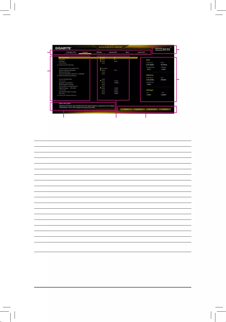
2-2 The Main Menu
Hardware
Information
Option Description Current Settings
Setup Menus
Conguration
Items
System
Time
Quick Access Bar allows you to quickly move to
the General Help, Easy Mode, Smart Fan 5, or
Q-Flash screen.
Advanced Mode Function Keys
<f><g>Move the selection bar to select a setup menu
<h><i>Movetheselectionbartoselectancongurationitemonamenu
<Enter>/Double Click Execute command or enter a menu
<+>/<Page Up> Increase the numeric value or make changes
<->/<Page Down> Decrease the numeric value or make changes
<F1> Show descriptions of the function keys
<F2> Switch to Easy Mode
<F3> SavethecurrentBIOSsettingstoaprole
<F4> LoadtheBIOSsettingsfromaprolecreatedbefore
<F5> RestorethepreviousBIOSsettingsforthecurrentsubmenus
<F6> Display the Smart Fan 5 screen
<F7> LoadtheOptimizedBIOSdefaultsettingsforthecurrentsubmenus
<F8> Access the Q—Flash utility
<F10> Save all the changes and exit the BIOS Setup program
<F11> Switch to the Favorites submenu
<F12> Capture the current screen as an image and save it to your USB drive
<Insert> Add or remove a favorite option
<Ctrl>+<S> Display information on the installed memory
<Esc> Main Menu: Exit the BIOS Setup program
Submenus: Exit current submenu
— 21 —
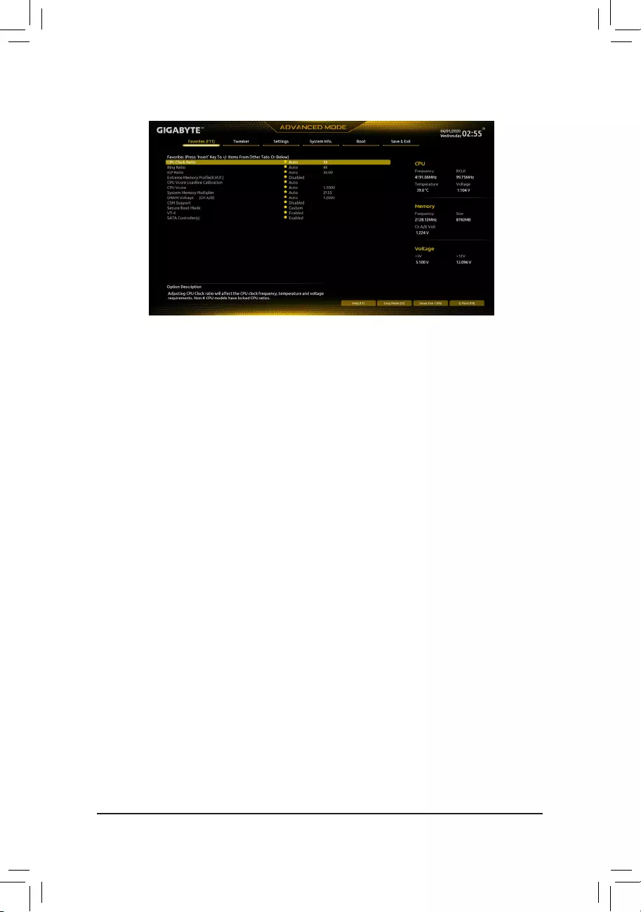
2-3 Favorites (F11)
Set your frequently used options as your favorites and use the <F11> key to quickly switch to the page where
all of your favorite options are located. To add or remove a favorite option, go to its original page and press
<Insert>ontheoption.Theoptionismarkedwithastarsignifsetasa»favorite.»
— 22 —
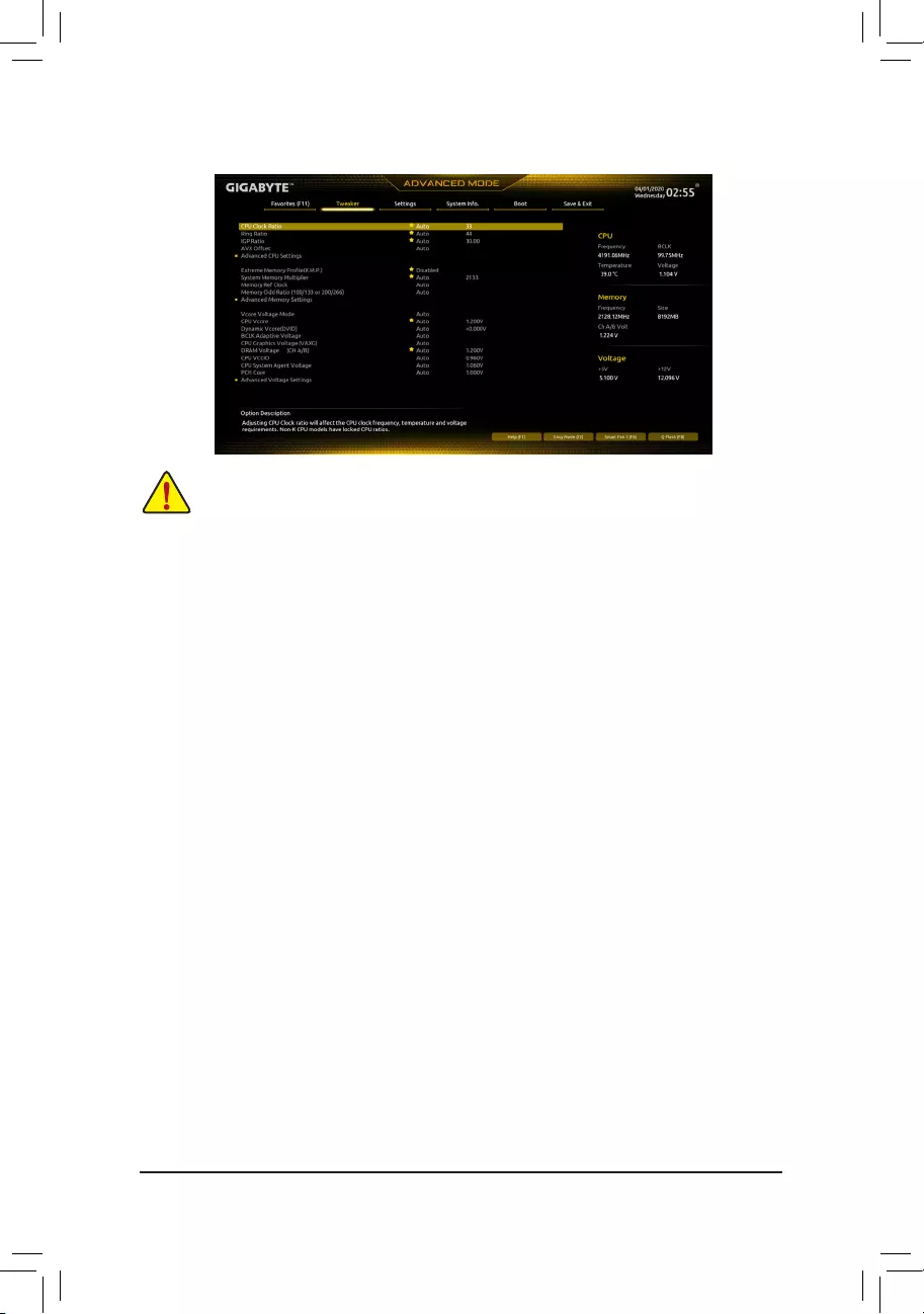
2-4 Tweaker
Whether the system will work stably with the overclock/overvoltage settings you made is dependent
onyouroverallsystemcongurations.Incorrectlydoingoverclock/overvoltagemayresultindamage
to CPU, chipset, or memory and reduce the useful life of these components. This page is for advanced
users only and we recommend you not to alter the default settings to prevent system instability or
other unexpected results. (Inadequately altering the settings may result in system’s failure to boot.
If this occurs, clear the CMOS values and reset the board to default values.)
&CPU Clock Ratio
Allows you to alter the clock ratio for the installed CPU. The adjustable range is dependent on the CPU
being installed.
&Ring Ratio
Allows you to set the CPU Uncore ratio. The adjustable range is dependent on the CPU being used.
(Default: Auto)
&IGP Ratio (Note)
AllowsyoutosettheGraphicsRatio.(Default:Auto)
&AVX Offset (Note)
AVX offset is the negative offset of AVX ratio.
Advanced CPU Settings
&CPU Over Temperature Protection (Note)
Allowsyoutone-tunetheTJMaxoffsetvalue.(Default:Auto)
&FCLK Frequency for Early Power On
AllowsyoutosettheFCLKfrequency.Optionsare:Normal(800Mhz),1GHz,400MHz.(Default:1GHz)
&Hyper-Threading Technology
Allows you to determine whether to enable multi-threading technology when using an Intel® CPU that
supports this function. This feature only works for operating systems that support multi—processor mode.
AutoletstheBIOSautomaticallycongurethissetting.(Default:Auto)
&No. of CPU Cores Enabled
Allows you to select the number of CPU cores to enable in an Intel® multi-core CPU (the number of CPU
cores may vary by CPU). AutoletstheBIOSautomaticallycongurethissetting.(Default:Auto)
(Note) ThisitemispresentonlywhenyouinstallaCPUthatsupportsthisfeature.Formoreinformation
about Intel® CPUs’ unique features, please visit Intel’s website.
— 23 —

&VT-d
Enables or disables Intel®VirtualizationTechnologyforDirectedI/O.(Default:Enabled)
&Intel(R) Speed Shift Technology (Intel® Speed Shift Technology) (Note)
Enables or disables Intel® Speed Shift Technology. Enabling this feature allows the processor to ramp up
its operating frequency more quickly and then improves the system responsiveness. (Default: Enabled)
&CPU Thermal Monitor (Note)
Enables or disables Intel® Thermal Monitor function, a CPU overheating protection function. When
enabled, the CPU core frequency and voltage will be reduced when the CPU is overheated. Auto lets
theBIOSautomaticallycongurethissetting.(Default:Auto)
&Ring to Core offset (Down Bin)
AllowsyoutodeterminewhethertodisabletheCPURingratioauto—downfunction.Auto lets the BIOS
automaticallycongurethissetting.(Default:Auto)
&CPU EIST Function (Note)
Enables or disables Enhanced Intel® Speed Step Technology (EIST). Depending on CPU loading, Intel®
EIST technology can dynamically and effectively lower the CPU voltage and core frequency to decrease
average power consumption and heat production. AutoletstheBIOSautomaticallycongurethissetting.
(Default: Auto)
&Race To Halt (RTH) (Note)/EnergyEfcientTurbo (Note)
Enables or disables the CPU power saving related settings. (Default: Auto)
&Voltage Optimization
Allowsyoutodeterminewhethertoenablevoltageoptimizationtoreducepowerconsumption.(Default:
Auto)
&Intel(R) Turbo Boost Technology (Note)
Allows you to determine whether to enable the Intel® CPU Turbo Boost technology. Auto lets the BIOS
automaticallycongurethissetting.(Default:Auto)
&Intel(R) Turbo Boost Max Technology 3.0 (Note)
Enables or disables Intel® Turbo Boost Max Technology 3.0. Intel® Turbo Boost Max Technology 3.0
allows the system to identify the processor’s best performance core and lets you manually direct the
most critical workloads to it. You can even adjust the frequency of each core individually for performance
optimization.(Default:NativeMode)
&CPU Flex Ratio Override
EnablesordisablestheCPUFlexRatio.ThemaximumCPUclockratiowillbebasedontheCPU Flex
Ratio Settings value if CPU Clock Ratio is set to Auto. (Default: Disabled)
&CPU Flex Ratio Settings
AllowsyoutosettheCPUFlexRatio.TheadjustablerangemayvarybyCPU.
dActive Turbo Ratios
&Turbo Ratio (1-Core Active~10—Core Active)
Allows you to set the CPU Turbo ratios for different number of active cores. Auto sets the CPU Turbo
ratiosaccordingtotheCPUspecications.
Thisitemiscongurableonlywhen
Active Turbo Ratios is
set
to
Enabled
.
(Default: Auto)
(Note) ThisitemispresentonlywhenyouinstallaCPUthatsupportsthisfeature.Formoreinformation
about Intel® CPUs’ unique features, please visit Intel’s website.
— 24 —

dC-States Control
&CPU Enhanced Halt (C1E)
Enables or disables Intel
®
CPU Enhanced Halt (C1E) function, a CPU power-saving function in system
halt state. When enabled, the CPU core frequency and voltage will be reduced during system halt state
to decrease power consumption. Auto lets the BIOSautomatically congure thissetting.
This item is
congurableonlywhen
C-States Control is set to
Enabled.
(Default: Auto)
&C3 State Support (Note)
Allows you to determine whether to let the CPU enter C3 mode in system halt state. When enabled, the
CPU core frequency and voltage will be reduced during system halt state to decrease power consumption.
The C3 state is a more enhanced power-saving state than C1. AutoletstheBIOSautomaticallycongure
thissetting.Thisitemiscongurableonlywhen
C-States Control is set to
Enabled.
(Default: Auto)
&C6/C7 State Support
Allows you to determine whether to let the CPU enter C6/C7 mode in system halt state. When enabled, the
CPU core frequency and voltage will be reduced during system halt state to decrease power consumption.
The C6/C7 state is a more enhanced power-saving state than C3. Auto lets the BIOS automatically
congurethissetting.ThisitemiscongurableonlywhenC-States Control is set to Enabled. (Default:
Auto)
&C8 State Support (Note)
Allows you to determine whether to let the CPU enter C8 mode in system halt state. When enabled, the
CPU core frequency and voltage will be reduced during system halt state to decrease power consumption.
The C8 state is a more enhanced power-saving state than C6/C7. Auto lets the BIOS automatically
congurethissetting.ThisitemiscongurableonlywhenC-States Control is set to Enabled. (Default:
Auto)
&C10 State Support (Note)
Allows you to determine whether to let the CPU enter C10 mode in system halt state. When enabled, the
CPU core frequency and voltage will be reduced during system halt state to decrease power consumption.
The C10 state is a more enhanced power-saving state than C8. AutoletstheBIOSautomaticallycongure
thissetting.ThisitemiscongurableonlywhenC-States Control is set to Enabled. (Default: Auto)
&Package C State Limit (Note)
Allows you to specify the C—state limit for the processor. AutoletstheBIOSautomaticallycongurethis
setting.ThisitemiscongurableonlywhenC-States Control is set to Enabled. (Default: Auto)
dTurbo Power Limits
Allows you to set a power limit for CPU Turbo mode. When the CPU power consumption exceeds the
speciedpowerlimit,theCPUwillautomaticallyreducethecorefrequencyinordertoreducethepower.
AutosetsthepowerlimitaccordingtotheCPUspecications.(Default:Auto)
&Package Power Limit TDP (Watts) / Package Power Limit Time
AllowsyoutosetthepowerlimitforCPUTurbomodeandhowlongittakestooperateatthespecied
powerlimit.Ifthespeciedvalueisexceeded,theCPUwillautomaticallyreducethecorefrequencyin
order to reduce the power. AutosetsthepowerlimitaccordingtotheCPUspecications.Thisitemis
congurableonlywhenTurbo Power Limits is set to Enabled. (Default: Auto)
&DRAM Power Limit (Watts) / DRAM Power Limit Time
AllowsyoutosetthepowerlimitformemoryTurbomodeandhowlongittakestooperateatthespecied
power limit. AutoletstheBIOSautomaticallycongurethissetting.Thisitemiscongurableonlywhen
Turbo Power Limits is set to Enabled. (Default: Auto)
(Note) ThisitemispresentonlywhenyouinstallaCPUthatsupportsthisfeature.Formoreinformation
about Intel® CPUs’ unique features, please visit Intel’s website.
— 25 —

&Core Current Limit (Amps)
AllowsyoutosetacurrentlimitforCPUTurbomode.WhentheCPUcurrentexceedsthespeciedcurrent
limit, the CPU will automatically reduce the core frequency in order to reduce the current. Auto sets
thepowerlimitaccordingtotheCPUspecications.ThisitemiscongurableonlywhenTurbo Power
Limits is set to Enabled. (Default: Auto)
dTurbo Per Core Limit Control (Note 1)
Allows you to control each CPU core limit separately. (Default: Auto)
&ExtremeMemoryProle(X.M.P.)(Note 2)
Allows the BIOS to read the SPD data on XMP memory module(s) to enhance memory performance
when enabled.
Disabled Disables this function. (Default)
Prole1 UsesProle1settings.
Prole2(Note2) UsesProle2settings.
&System Memory Multiplier
Allows you to set the system memory multiplier. Auto sets memory multiplier according to memory SPD
data. (Default: Auto)
&Memory Ref Clock
Allows you to manually adjust the memory reference clock. (Default: Auto)
&Memory Odd Ratio (100/133 or 200/266)
Enabled allows Qclk to run in odd frequency. (Default: Auto)
Advanced Memory Settings
&Memory Multiplier Tweaker
Provides different levels of memory auto—tuning. (Default: Auto)
&Channel Interleaving
Enables or disables memory channel interleaving. Enabled allows the system to simultaneously access
different channels of the memory to increase memory performance and stability. Auto lets the BIOS
automaticallycongurethissetting.(Default:Auto)
&Rank Interleaving
Enables or disables memory rank interleaving. Enabled allows the system to simultaneously access
different ranks of the memory to increase memory performance and stability. Auto lets the BIOS
automaticallycongurethissetting.(Default:Auto)
&Memory Boot Mode
Provides memory detection and training methods.
Auto LetstheBIOSautomaticallycongurethissetting.(Default)
Normal TheBIOSautomaticallyperformsmemorytraining.Pleasenotethatifthesystem
becomes unstable or unbootable, try to clear the CMOS values and reset the
boardtodefaultvalues.(Refertotheintroductionsofthebattery/clearCMOS
jumper in Chapter 1 for how to clear the CMOS values.)
EnableFastBoot Skipmemorydetectionandtraininginsomespeciccriteriaforfastermemory
boot.
Disable Fast Boot Detect and train memory at every single boot.
&Realtime Memory Timing
Allowsyoutone-tunememorytimingsaftertheBIOSstage.(Default:Auto)
(Note1) ThisitemispresentonlywhenyouinstallaCPUthatsupportsthisfeature.Formoreinformation
about Intel® CPUs’ unique features, please visit Intel’s website.
(Note2) ThisitemispresentonlywhenyouinstallaCPUandamemorymodulethatsupportthisfeature.
— 26 —

&Memory Enhancement Settings
Providesseveralmemory performance enhancementsettings:Auto,RelaxOC,EnhancedStability,
Normal(basicperformance),EnhancedPerformance,HighFrequency,HighDensity,andDDR-4500+.
(Default: Auto)
&Memory Channel Detection Message
Allows you to determine whether to show an alert message when the memory is not installed in the
optimal memory channel. (Default: Enabled)
SPD Info
Displays information on the installed memory.
Memory Channels Timings
d Channels Standard Timing Control, Channels Advanced Timing Control, Channels
Misc Timing Control
Thesesectionsprovidememorytimingsettings.Note:Yoursystemmaybecomeunstableorfailtoboot
after you make changes on the memory timings. If this occurs, please reset the board to default values
byloadingoptimizeddefaultsorclearingtheCMOSvalues.
& Vcore Voltage Mode/CPU Vcore/Dynamic Vcore(DVID)/BCLK Adaptive Voltage/CPU
Graphics Voltage (VAXG)/DRAM Voltage (CH A/B)/CPU VCCIO/CPU System Agent
Voltage/PCH Core
These items allow you to adjust the CPU Vcore and memory voltages.
Advanced Voltage Settings
ThissubmenuallowsyoutocongureLoad—LineCalibrationlevel,over-voltageprotectionlevel,and
over-current protection level.
— 27 —

2-5 Settings
Platform Power
&Platform Power Management
Enables or disables the Active State Power Management function (ASPM). (Default: Disabled)
&PEG ASPM
AllowsyoutoconguretheASPMmodeforthedeviceconnectedtotheCPUPEGbus.Thisitemis
congurableonlywhenPlatform Power Management is set to Enabled. (Default: Disabled)
&PCH ASPM
AllowsyoutoconguretheASPMmodeforthedeviceconnectedtoChipset‘sPCIExpressbus.This
itemiscongurableonlywhenPlatform Power Management is set to Enabled. (Default: Disabled)
&DMI ASPM
AllowsyoutoconguretheASPMmodeforbothCPUsideandChipsetsideoftheDMIlink.Thisitem
iscongurableonlywhenPlatform Power Management is set to Enabled. (Default: Disabled)
&Power On By Keyboard
Allows the system to be turned on by a PS/2 keyboard wake-up event.
Note:Tousethisfunction,youneedanATXpowersupplyprovidingatleast1Aonthe+5VSBlead.
Disabled Disables this function. (Default)
Password Set a password with 1~5 characters to turn on the system.
Keyboard98 PressPOWERbuttonontheWindows98keyboardtoturnonthesystem.
Any Key Press any key to turn on the system.
&Power On Password
Set the password when Power On By Keyboard is set to Password.
Press <Enter> on this item and set a password with up to 5 characters and then press <Enter> to accept.
To turn on the system, enter the password and press <Enter>.
Note:To cancelthepassword,press <Enter>onthisitem.Whenpromptedforthepassword,press
<Enter> again without entering the password to clear the password settings.
&Power On By Mouse
Allows the system to be turned on by a PS/2 mouse wake-up event.
Note:Tousethisfunction,youneedanATXpowersupplyprovidingatleast1Aonthe+5VSBlead.
Disabled Disables this function. (Default)
Move Move the mouse to turn on the system.
Double Click Double click on left button on the mouse to turn on the system.
— 28 —

&ErP
Determines whether to let the system consume least power in S5 (shutdown) state. (Default: Disabled)
Note:WhenthisitemissettoEnabled,thefollowingfunctionswillbecomeunavailable:Resumeby
Alarm, power on by mouse, and power on by keyboard.
&Soft—Off by PWR-BTTN
ConguresthewaytoturnoffthecomputerinMS—DOSmodeusingthepowerbutton.
Instant-Off Press the power button and then the system will be turned off instantly. (Default)
Delay 4 Sec. Press and hold the power button for 4 seconds to turn off the system. If the power
button is pressed for less than 4 seconds, the system will enter suspend mode.
&Resume by Alarm
Determines whether to power on the system at a desired time. (Default: Disabled)
If enabled, set the date and time as following:
Wakeupday:Turnonthesystemataspecictimeoneachdayoronaspecicdayinamonth.
Wake up hour/minute/second: Set the time at which the system will be powered on automatically.
Note:Whenusingthisfunction,avoidinadequateshutdownfromtheoperatingsystemorremovalofthe
AC power, or the settings may not be effective.
&Power Loading
Enables or disables dummy load. When the power supply is at low load, a self-protection will activate
causing it to shutdown or fail. If this occurs, please set to Enabled. Auto lets the BIOS automatically
congurethissetting.(Default:Auto)
&RC6(Render Standby)
Allows you to determine whether to let the onboard graphics enter standby mode to decrease power
consumption. (Default: Enabled)
&AC BACK
Determines the state of the system after the return of power from an AC power loss.
Memory The system returns to its last known awake state upon the return of the AC power.
Always On The system is turned on upon the return of the AC power.
Always Off The system stays off upon the return of the AC power. (Default)
IO Ports
&Initial Display Output
SpeciestherstinitiationofthemonitordisplayfromtheinstalledPCIExpressgraphicscardorthe
onboard graphics.
IGFX(Note) Setstheonboardgraphicsastherstdisplay.
PCIe1Slot SetsthegraphicscardonthePCIEX16slotastherstdisplay.(Default)
&Internal Graphics
Enables or disables the onboard graphics function. (Default: Auto)
&DVMT Pre-Allocated
Allowsyoutosettheonboardgraphicsmemorysize.Optionsare:0M~512M.(Default:64M)
&DVMT Total Gfx Mem
AllowsyoutoallocatetheDVMTmemorysizeoftheonboardgraphics.Optionsare:128M,256M,MAX.
(Default: 256M)
&Aperture Size
Allows you to set the maximum amount of system memory that can be allocated to the graphics card.
Options are: 128MB, 256MB, 512MB, 1024MB, and 2048MB. (Default: 256MB)
&OnBoard LAN Controller
EnablesordisablestheonboardLANfunction.(Default:Enabled)
Ifyouwishtoinstalla3rdpartyadd-innetworkcardinsteadofusingtheonboardLAN,setthisitemto
Disabled.
(Note) ThisitemispresentonlywhenyouinstallaCPUthatsupportsthisfeature.
— 29 —

&Audio Controller
Enables or disables the onboard audio function. (Default: Enabled)
If you wish to install a 3rd party add-in audio card instead of using the onboard audio, set this item to
Disabled.
&Above 4G Decoding
Enables or disables 64—bit capable devices to be decoded in above 4 GB address space (only if your
system supports 64-bit PCI decoding). Set to Enabled if more than one advanced graphics card are
installed and their drivers are not able to be launched when entering the operating system (because of
the limited 4 GB memory address space). (Default: Disabled)
&IOAPIC 24-119 Entries
Enables or disables this function. (Default: Enabled)
SuperIOConguration
&Serial Port 1 (Onboard COMA Connector)
Enables or disables the onboard serial port. (Default: Enabled)
&Serial Port 2 (Onboard COMB Connector)
Enables or disables the onboard serial port. (Default: Enabled)
USBConguration
&Legacy USB Support
Allows USB keyboard/mouse to be used in MS—DOS. (Default: Enabled)
&XHCI Hand-off
Determines whether to enable XHCI Hand—off feature for an operating system without XHCI Hand—off
support. (Default: Enabled)
&USB Mass Storage Driver Support
Enables or disables support for USB storage devices. (Default: Enabled)
&Mass Storage Devices
Displays a list of connected USB mass storage devices. This item appears only when a USB storage
device is installed.
NetworkStackConguration
&Network Stack
Disables or enables booting from the network to install a GPT format OS, such as installing the OS from
the Windows Deployment Services server. (Default: Disabled)
&IPv4 PXE Support
EnablesordisablesIPv4PXESupport.ThisitemiscongurableonlywhenNetwork Stack is enabled.
&IPv4 HTTP Support
EnablesordisablesHTTPbootsupportforIPv4.ThisitemiscongurableonlywhenNetwork Stack is
enabled.
&IPv6 PXE Support
EnablesordisablesIPv6PXESupport.ThisitemiscongurableonlywhenNetwork Stack is enabled.
&IPv6 HTTP Support
EnablesordisablesHTTPbootsupportforIPv6.ThisitemiscongurableonlywhenNetwork Stack is
enabled.
&PXE boot wait time
Allowsyoutocongurehowlongtowaitbeforeyoucanpress<Esc>toabortthePXEboot.
&Media detect count
Allows you to set the number of times to check the presence of media.
— 30 —
Only for the B460M DS3H.

NVMeConguration
DisplaysinformationonyourM.2NVMEPCIeSSDifinstalled.
SATAAndRSTConguration
&SATA Controller(s)
Enables or disables the integrated SATA controllers. (Default: Enabled)
&SATA Mode Selection
EnablesordisablesRAIDfortheSATAcontrollersintegratedintheChipsetorcongurestheSATA
controllers to AHCI mode.
IntelRSTPremiumWithIntelOptaneSystemAcceleration EnablesRAIDfortheSATAcontroller.
AHCI CongurestheSATAcontrollerstoAHCImode.AdvancedHostControllerInterface
(AHCI)isaninterfacespecicationthatallowsthestoragedrivertoenableadvanced
SerialATAfeaturessuchasNativeCommandQueuingandhotplug.(Default)
&Aggressive LPM Support
Enables or disables the power saving feature, ALPM (Aggressive Link Power Management), for the
Chipset SATA controllers. (Default: Disabled)
&Port 0/1/2/3/4/5
Enables or disables each SATA port. (Default: Enabled)
&Hot plug
Enables or disable the hot plug capability for each SATA port. (Default: Disabled)
&ConguredaseSATA
Enables or disables support for external SATA devices.
EZ RAID
AllowsyoutoquicklysetupaRAIDarray.RefertoChapter3,»ConguringaRAIDSet,»forinstructions
onconguringaRAIDarray.
Realtek PCIe GBE Family Controller
Thissub—menuprovidesinformationonLANcongurationandrelatedcongurationoptions.
Miscellaneous
&LEDs in System Power On State
Allows you to enable or disable motherboard LED lighting when the system is on.
Off Disables the selected lighting mode when the system is on.
On Enables the selected lighting mode when the system is on. (Default)
&LEDs in Sleep, Hibernation, and Soft Off States
Allows you to set the lighting mode of the motherboard LEDs in system S3/S4/S5 state.
ThisitemiscongurablewhenLEDs in System Power On State is set to On.
Off Disables the selected lighting mode when the system enters S3/S4/S5 state. (Default)
On Enables the selected lighting mode when the system enters S3/S4/S5 state.
&Intel Platform Trust Technology (PTT)
Enables or disables Intel® PTT Technology. (Default: Disabled)
&Software Guard Extensions (SGX)
Enables or disables the Intel® Software Guard Extensions technology. This feature allows legal software
to operate in a safe environment and protects the software against attacks from malicious software. The
Software Controlled option allows you to enable or disable this feature with an Intel-provided application.
(Default: Software Controlled)
&Max Link Speed
Allows you to set the operation mode of the PCI Express slots to Gen 1, Gen 2, or Gen 3. Actual operation
modeissubjecttothehardwarespecicationofeachslot.AutoletstheBIOSautomaticallycongure
this setting. (Default: Auto)
— 31 —

&3DMark01 Enhancement
Allows you to determine whether to enhance some legacy benchmark performance. (Default: Disabled)
Trusted Computing
Enables or disables Trusted Platform Module (TPM).
PC Health Status
&Reset Case Open Status
Disabled Keeps or clears the record of previous chassis intrusion status. (Default)
Enabled Clears the record of previous chassis intrusion status and the Case Openeldwill
show»No»atnextboot.
&Case Open
Displays the detection status of the chassis intrusion detection device attached to the motherboard CI
header.Ifthesystemchassiscoverisremoved,thiseldwillshow»Yes»,otherwiseitwillshow»No».To
clear the chassis intrusion status record, set Reset Case Open Status to Enabled, save the settings
to the CMOS, and then restart your system.
& CPU Vcore/CPU VCCSA/DRAM Channel A/B Voltage/+3.3V/ +5V/+12V/CPU VAXG
Displays the current system voltages.
Smart Fan 5
&Monitor
Allowsyoutoselectatargettomonitorandtomakefurtheradjustment.(Default:CPUFAN)
&Fan Speed Control
Allows you to determine whether to enable the fan speed control function and adjust the fan speed.
Normal Allowsthefantorunatdifferentspeedsaccordingtothetemperature.Youcanadjust
the fan speed with System Information Viewer based on your system requirements.
(Default)
Silent Allows the fan to run at slow speeds.
Manual Allows you to control the fan speed in the curve graph.
Full Speed Allows the fan to run at full speeds.
&Fan Control Use Temperature Input
Allows you to select the reference temperature for fan speed control.
&Temperature Interval
Allows you to select the temperature interval for fan speed change.
&Fan Control Mode
Auto Lets the BIOS automatically detect the type of fan installed and sets the optimal control
mode. (Default)
Voltage Voltage mode is recommended for a 3—pin fan.
PWM PWM mode is recommended for a 4—pin fan.
&Fan Stop
Enables or disables the fan stop function. You can set the temperature limit using the temperature curve.
The fan stops operation when the temperature is lower than the limit. (Default: Disabled)
&Temperature
Displays the current temperature of the selected target area.
&Fan Speed
Displays current fan speeds.
&Temperature Warning Control
Sets the warning threshold for temperature. When temperature exceeds the threshold, BIOS will emit
warning sound. Options are: Disabled (default), 60oC/140oF, 70oC/158oF, 8 0 oC/176oF, 90 oC/194oF.
&Fan Fail Warning
Allows the system to emit warning sound if the fan is not connected or fails. Check the fan condition or
fan connection when this occurs. (Default: Disabled)
— 32 —

2-6 System Info.
This section provides information on your motherboard model and BIOS version. You can also select the
default language used by the BIOS and manually set the system time.
&Access Level
Displays the current access level depending on the type of password protection used. (If no password
is set, the default will display as Administrator.) The Administrator level allows you to make changes to
all BIOS settings; the User level only allows you to make changes to certain BIOS settings but not all.
&System Language
Selects the default language used by the BIOS.
&System Date
Sets the system date. The date format is week (read—only), month, date, and year. Use <Enter> to switch
betweentheMonth,Date,andYeareldsandusethe<PageUp>or<PageDown>keytosetthedesired
value.
&System Time
Sets the system time. The time format is hour, minute, and second. For example, 1 p.m. is 13:00:00.
Use<Enter>toswitchbetweentheHour,Minute,andSecondeldsandusethe<PageUp>or<Page
Down> key to set the desired value.
Plug in Devices Info
Displays information on your PCI Express and M.2 devices if installed.
Q—Flash
AllowsyoutoaccesstheQ—FlashutilitytoupdatetheBIOSorbackupthecurrentBIOSconguration.
— 33 —

2-7 Boot
&Bootup NumLock State
EnablesordisablesNumlockfeatureonthenumerickeypadofthekeyboardafterthePOST.(Default:On)
&Security Option
Specieswhetherapasswordisrequiredeverytimethesystemboots,oronlywhenyouenterBIOSSetup.
Afterconguringthisitem,setthepassword(s)undertheAdministrator Password/User Password
item.
Setup A password is only required for entering the BIOS Setup program.
System A password is required for booting the system and for entering the BIOS Setup
program. (Default)
&Full Screen LOGO Show
Allows you to determine whether to display the GIGABYTE Logo at system startup. Disabled skips the
GIGABYTE Logo when the system starts up. (Default: Enabled)
&Boot Option Priorities
Speciestheoverallbootorderfromtheavailabledevices.Removablestoragedevicesthatsuppor tGPT
formatwillbeprexedwith»UEFI:»stringonthebootdevicelist.Tobootfromanoperatingsystemthat
supportsGPTpartitioning,selectthedeviceprexedwith»UEFI:»string.
Or if you want to install an operating system that supports GPT partitioning such as Windows 10 64—bit,
selecttheopticaldrivethatcontainstheWindows1064-bitinstallationdiscandisprexedwith»UEFI:»
string.
&Fast Boot
Enables or disables Fast Boot to shorten the OS boot process. (Default: Disable Link)
&SATA Support
Last Boot SATA Devices Only Except for the previous boot drive, all SATA devices are disabled
before the OS boot process completes. (Default)
All Sata Devices All SATA devices are functional in the operating system and during the
POST.
ThisitemiscongurableonlywhenFast Boot is set to Enabled or Ultra Fast.
&VGA Support
Allows you to select which type of operating system to boot.
Auto EnableslegacyoptionROMonly.
EFIDriver EnablesEFIoptionROM.(Default)
ThisitemiscongurableonlywhenFast Boot is set to Enabled or Ultra Fast.
— 34 —

&USB Support
Disable Link All USB devices are disabled before the OS boot process completes.
Full Initial All USB devices are functional in the operating system and during the POST.
(Default)
Partial Initial Part of the USB devices are disabled before the OS boot process completes.
ThisitemiscongurableonlywhenFast Boot is set to Enabled or Ultra Fast.
&PS2 Devices Support
Disabled Link All PS/2 devices are disabled before the OS boot process completes.
Enabled All PS/2 devices are functional in the operating system and during the POST.
(Default)
ThisitemiscongurableonlywhenFast Boot is set to Enabled or Ultra Fast.
&NetWork Stack Driver Support
Disable Link Disables booting from the network. (Default)
Enabled Enables booting from the network.
ThisitemiscongurableonlywhenFast Boot is set to Enabled or Ultra Fast.
&Next Boot After AC Power Loss
NormalBoot EnablesnormalbootupuponthereturnoftheACpower.(Default)
Fast Boot Keeps the Fast Boot settings upon the return of the AC power.
ThisitemiscongurableonlywhenFast Boot is set to Enabled or Ultra Fast.
&Mouse Speed
Allows you to set the mouse cursor movement speed. (Default: 1 X)
&Windows 10 Features
Allows you to select the operating system to be installed. (Default: Windows 10)
&CSM Support
Enables or disables UEFI CSM (Compatibility Support Module) to support a legacy PC boot process.
Enabled Enables UEFI CSM.
Disabled Disables UEFI CSM and supports UEFI BIOS boot process only. (Default)
&LAN PXE Boot Option ROM
AllowsyoutoselectwhethertoenablethelegacyoptionROMfortheLANcontroller.(Default:Disabled)
ThisitemiscongurableonlywhenCSM Support is set to Enabled.
&Storage Boot Option Control
AllowsyoutoselectwhethertoenabletheUEFIorlegacyoptionROMforthestoragedevicecontroller.
Donotlaunch DisablesoptionROM.
UEFI EnablesUEFIoptionROMonly.
Legacy EnableslegacyoptionROMonly.(Default)
ThisitemiscongurableonlywhenCSM Support is set to Enabled.
&Other PCI devices
AllowsyoutoselectwhethertoenabletheUEFIorLegacyoptionROMforthePCIdevicecontroller
otherthantheLAN,storagedevice,andgraphicscontrollers.
Donotlaunch DisablesoptionROM.
UEFI EnablesUEFIoptionROMonly.(Default)
Legacy EnableslegacyoptionROMonly.
ThisitemiscongurableonlywhenCSM Support is set to Enabled.
— 35 —

&Administrator Password
Allowsyoutocongureanadministratorpassword.Press<Enter>onthisitem,typethepassword,and
thenpress<Enter>.Youwillberequestedtoconrmthepassword.Typethepasswordagainandpress
<Enter>. You must enter the administrator password (or user password) at system startup and when
entering BIOS Setup. Differing from the user password, the administrator password allows you to make
changes to all BIOS settings.
&User Password
Allowsyoutocongureauserpassword.Press<Enter>onthisitem,typethepassword,andthenpress
<Enter>.Youwillberequestedtoconrmthepassword.Typethepasswordagainandpress<Enter>.
You must enter the administrator password (or user password) at system startup and when entering BIOS
Setup. However, the user password only allows you to make changes to certain BIOS settings but not
all.
To cancel the password, press <Enter> on the password item and when requested for the password, enter
thecorrectonerst.Whenpromptedforanewpassword,press<Enter>withoutenteringanypassword.
Press<Enter>againwhenpromptedtoconrm.
NOTE:BeforesettingtheUserPassword,besuretosettheAdministratorPasswordrst.
Secure Boot
AllowsyoutoenableordisableSecureBootandcongurerelatedsettings.Thisitemiscongurable
only when CSM Support is set to Disabled.
&Preferred Operating Mode
Allows you to select whether to enter Easy mode or Advanced mode after entering BIOS Setup. Auto
enters the BIOS mode where it was last time. (Default: Auto)
— 36 —

2-8 Save & Exit
&Save & Exit Setup
Press <Enter> on this item and select Yes. This saves the changes to the CMOS and exits the BIOS
Setup program. Select No or press <Esc> to return to the BIOS Setup Main Menu.
&Exit Without Saving
Press <Enter> on this item and select Yes. This exits the BIOS Setup without saving the changes made
in BIOS Setup to the CMOS. Select No or press <Esc> to return to the BIOS Setup Main Menu.
&Load Optimized Defaults
Press <Enter> on this item and select Yes to load the optimal BIOS default settings. The BIOS defaults
settingshelpthesystemtooperateinoptimumstate.AlwaysloadtheOptimizeddefaultsafterupdating
the BIOS or after clearing the CMOS values.
&Boot Override
Allows you to select a device to boot immediately. Press <Enter> on the device you select and select
Yestoconrm.Yoursystemwillrestartautomaticallyandbootfromthatdevice.
&SaveProles
ThisfunctionallowsyoutosavethecurrentBIOSsettingstoaprole.Youcancreateupto8proles
andsaveasSetupProle1~SetupProle8.Press<Enter>tocomplete.OryoucanselectSelect File
in HDD/FDD/USBtosavetheproletoyourstoragedevice.
&LoadProles
If your system becomes unstable and you have loaded the BIOS default settings, you can use this function
toloadtheBIOSsettingsfromaprolecreatedbefore,withoutthehasslesofreconguringtheBIOS
settings.Firstselecttheproleyouwishtoloadandthenpress<Enter>tocomplete.Youcanselect
Select File in HDD/FDD/USBtoinputtheprolepreviouslycreatedfromyourstoragedeviceorload
theproleautomaticallycreatedbytheBIOS,suchasrevertingtheBIOSsettingstothelastsettings
that worked properly (last known good record).
— 37 —

Chapter 3 Appendix
Before you begin, please prepare the following items:
•At least two SATA hard drives or SSDs. (Note1) (To ensure optimal performance, it is recommended that you
use two hard drives with identical model and capacity). (Note2)
•Windows setup disc.
•Motherboard driver disc.
•A USB thumb drive.
ConguringtheOnboardSATAController
A. Installing SATA hard drive(s) in your computer
Install the hard drives/SSDs in the Intel® Chipset controlled connectors on the motherboard. Then connect
the power connectors from your power supply to the hard drives.
B.ConguringSATAcontrollermodeinBIOSSetup
MakesuretoconguretheSATAcontrollermodecorrectlyinsystemBIOSSetup.
Steps:
1. Turn on your computer and press <Delete> to enter BIOS Setup during the POST (Power-On Self—Test). Go
to SettingsIOPortsSATAAndRSTConguration, make sure SATA Controller(s) is enabled. To create
RAID,setSATA Mode Selection to Intel RST Premium With Intel Optane System Acceleration. Then
savethesettingsandrestartyourcomputer.Note:WhenusingaPCIeSSD,makesuretosettheUse RST
Legacy OROM item under SettingsIOPortsSATAAndRSTConguration to Disabled and RST Control
PCIe Storage Devices to Manual. Then depending the M.2 connector you use, set the corresponding
PCIe Storage Dev On Port XX item to RST Controlled. Finally, save the settings and exit BIOS Setup.
IfyouwanttouseNVMePCIeSSDstocongureRAID,makesuretosetNVMe RAID mode to Enabled.
2. TousetheEZRAIDfeature,followthestepsin»C-1.»TocongureUEFIRAID,followthestepsin»C-2.«
ToenterthelegacyRAIDROM,referto«C-3«formoreinformation.Finally,savethesettingsandexit
BIOS Setup.
3-1 ConguringaRAIDSet
The BIOS Setup menus described in this section may differ from the exact settings for your
motherboard. The actual BIOS Setup menu options you will see shall depend on the motherboard
you have and the BIOS version.
C-1. Using EZ RAID
GIGABYTEmotherboardsprovideyouwiththeEZRAIDfeature,allowingyoutoquicklycongureaRAID
arraywithsimpliedsteps.
Steps:
1. After restarting the computer, enter the BIOS Setup and go to Settings. Press <Enter> on the EZ RAID
item.SelectthetypeofharddrivesyouuseforRAIDintheType tab and then press <Enter>.
2. Go to the ModetabtoselectaRAIDlevel.RAIDlevelssupportedincludeRAID0,RAID1,RAID10,and
RAID5(theselectionsavailabledependonthenumberoftheharddrivesbeinginstalled).Thenpress
<Enter> to move to the Create tab. Click Proceed to begin.
(Note1)
AnM.2PCIeSSDcannotbeusedtosetupaRAIDseteitherwithanM.2SATASSDoraSATAharddrive.
(Note2) Referto»InternalConnectors»fortheinstallationnoticesfortheM.2andSATAconnectors.
RAID Levels
RAID 0 RAID 1 RAID 5 RAID 10
Minimum
NumberofHard
Drives
≥2 2≥3 4
Array Capacity Numberofhard
drives*Sizeofthe
smallest drive
Sizeofthesmallest
drive
(Numberofhard
drives-1)*Sizeof
the smallest drive
(Numberofhard
drives/2)*Sizeofthe
smallest drive
Fault Tolerance No Yes Yes Yes
— 38 —

C-2.UEFIRAIDConguration
Steps:
1. In BIOS Setup, go to Boot and set CSM Support to Disabled. Save the changes and exit BIOS Setup.
2. After the system reboot, enter BIOS Setup again. Then enter the SettingsIO PortsIntel(R) Rapid
Storage Technology sub-menu.
3. On the Intel(R) Rapid Storage Technology menu, press <Enter> on Create RAID Volume to enter the Create
RAID Volume screen. Enter a volume name with 1~16 letters (letters cannot be special characters) under the
Nameitemandpress<Enter>.Then,selectaRAIDlevel.RAIDlevelssupportedincludeRAID0,RAID1,
RAID10,andRAID5(theselectionsavailabledependonthenumberoftheharddrivesbeinginstalled).Next,
use the down arrow key to move to Select Disks.
4. Under Select Disksitem,selecttheharddrivestobeincludedintheRAIDarray.Pressthe<Space>key
ontheharddrivestobeselected(selectedharddrivesaremarkedwith«X»).Thensetthestripeblock
size.Thestripeblocksizecanbesetfrom4KBto128KB.Onceyouhaveselectedthestripeblocksize,
set the volume capacity.
5. After setting the capacity, move to Create Volume and press <Enter> to begin.
6. After completing, you’ll be brought back to the Intel(R) Rapid Storage Technology screen. Under RAID
VolumesyoucanseethenewRAIDvolume.Toseemoredetailedinformation,press<Enter>onthe
volumetocheckforinformationonRAIDlevel,stripeblocksize,arrayname,andarraycapacity,etc.
PleasevisitGIGABYTE’swebsitefordetailsonconguringaRAIDarray.
C-3.ConguringLegacyRAIDROM
You’llneedadiscretegraphicscardtoenterthelegacyRAIDROMutility.Enter the Intel®legacyRAIDBIOS
setuputilitytocongureaRAIDarray.SkipthisstepandproceedwiththeinstallationofWindowsoperating
systemforanon—RAIDconguration.
Steps:
1. In BIOS Setup, go to Boot and set CSM Support to Enabled and Storage Boot Option Control to Legacy.
Next,gotoSettingsIOPortsSATAAndRSTConguration and make sure Use RST Legacy OROM
is set to Enabled. Save the changes and exit BIOS Setup. After the POST memory test begins and before
theoperatingsystembootbegins,lookforamessagewhichsays«Press<Ctrl-I>toenterConguration
Utility».Press<Ctrl>+<I>toentertheRAIDCongurationUtility.
2. After you press <Ctrl> + <I>, the MAIN MENUscreenwillappear.IfyouwanttocreateaRAIDarray,select
Create RAID VolumeinMAINMENUandpress<Enter>.
3. After entering the CREATE VOLUME MENU screen, enter a volume name with 1~16 letters (letters cannot
be special characters) under the Nameitemandpress<Enter>.Then,selectaRAIDlevel.RAIDlevels
supportedincludeRAID0,RAID1,RAID10,andRAID5(theselectionsavailabledependonthenumber
of the hard drives being installed). Press <Enter> to proceed.
4. Under Disksitem,selecttheharddrivestobeincludedintheRAIDarray.Ifonlytwoharddrivesare
installed,theywillbeautomaticallyassignedtothearray.Setthestripeblocksizeifnecessary.Thestripe
blocksizecanbesetfrom4KBto128KB.Onceyouhaveselectedthestripeblocksize,press<Enter>.
5. Enter the array capacity and press <Enter>. Finally press <Enter> on the Create Volume item to begin
creatingtheRAIDarray.Whenpromptedtoconrmwhethertocreatethisvolume,press<Y>toconrm
or<N>tocancel.
6. When completed,youcan see detailed information about the RAIDarray in the DISK/VOLUME
INFORMATIONsection,includingtheRAIDlevel,stripeblocksize,arrayname,andarraycapacity,etc.
ToexittheRAIDBIOSutility,press<Esc>orselect6. Exit in MAIN MENU.
3. After completing, you’ll be brought back to the Intel(R) Rapid Storage Technology screen. Under RAID
VolumesyoucanseethenewRAIDvolume.Toseemoredetailedinformation,press<Enter>onthe
volumetocheckforinformationonRAIDlevel,stripeblocksize,arrayname,andarraycapacity,etc.
— 39 —

3-2 Installing an Intel® Optane™ Memory
System Requirements
1. Intel® Optane™ memory
2. The Optane™ memory must have at least 16 GB capacity, and it must have equal or smaller capacity than
the hard drive/SSD to be accelerated.
3. The Optane™memorycannotbeusedtoaccelerateanexistingRAIDarray;theacceleratedharddrive/
SSDcannotbeincludedinaRAIDarray.
4. The hard drive/SSD to be accelerated must be a SATA hard drive or M.2 SATA SSD.
5. The hard drive/SSD to be accelerated can be a system drive or data drive. The system drive must be
GPT formatted and have Windows 10 64—bit (or later version) installed on it. The data drive must also be
GPT formatted.
6. The motherboard driver disc
Installation Guidelines
A-1: Installation in AHCI mode
IftheSATAcontrollerhasbeenconguredinAHCImode,pleasefollowthestepsbelow:
1. After entering the operating system, insert the motherboard driver disc into your optical drive. On the
Xpress Install screen, select Intel(R) Optane(TM) Memory System Acceleration (Note) to install. Follow
the on-screen instructions to continue. When completed, restart the system.
2. After re—entering the operating system, follow the on-screen instructions to complete the settings, and then
the Intel® Optane™ Memory application will appear automatically. Click Enable. All data on the Optane™
memory will be erased. Make sure you back up the data before continuing. Follow the on-screen instructions
to proceed. When completed, restart the system.
3. Launch the Intel® Optane™ Memory application from the Start menu and make sure the Intel® Optane™
Memory has been enabled. (The SATA controller mode is changed to Intel RST Premium With Intel
Optane System AccelerationfromAHCImode.DONOTchangeyourSATAcontrollermodebackto
AHCI. Doing so will cause the Optane™ memory unable to function properly.)
4. Ifyouwanttoacceleratethesystemdrive,youcanselectspecicfolders,les,orapplicationstoaccelerate
using the Intel
®
Optane
™
Memory Pinning function. (The Optane
™
memory used must have at least 32 GB
capacity.)
(Note) IfthesystemalreadyhasIntel®RapidStorageTechnologyutilityinstalled,youhavetoremoveit
rstbeforeinstallingtheIntel(R)Optane(TM)MemorySystemAccelerationapplication.
Install the RAID driver and operating system
With the correct BIOS settings, you are ready to install the operating system.
Installing the Operating System
AssomeoperatingsystemsalreadyincludeRAIDdriver,youdonotneedtoinstallseparateRAIDdriverduring
the Windows installation process. After the operating system is installed, we recommend that you install all
requireddriversfromthemotherboarddriverdiscusing»XpressInstall»toensuresystemperformanceand
compatibility.IftheoperatingsystemtobeinstalledrequiresthatyouprovideadditionalSATARAIDdriver
during the OS installation process, please refer to the steps below:
1. Copy the IRST folder under Boot in the driver disc to your USB thumb drive.
2. Boot from the Windows setup disc and perform standard OS installation steps. When the screen requesting
you to load the driver appears, select Browse.
3. ThenbrowsetotheUSBashdriveandselectthelocationofthedriver.Thelocationofthedriverisas
follows:IRSTf6py-x64
4. When a screen as shown, select Intel(R) Chipset SATA/PCIe RST Premium Controller and click Next
to load the driver and continue the OS installation.
— 40 —

A-2: Installation in Intel RST Premium With Intel Optane System Acceleration mode
IftheSATAcontrollerhasbeenconguredin Intel RST Premium With Intel Optane System Acceleration
mode, please follow the steps below:
1. After system restarts, go to the BIOS Setup, make sure CSM Support under the Boot menu is disabled.
2. Go to SettingsIOPortsSATAAndRSTConguration and make sure USE RST Legacy OROM is
disabled and RST Control PCIe Storage Devices is set to Manual. If you want to enable the Optane™
memory installed in the M2M_SB connector, set PCIe Storage Device On Port 21 to RST Controlled.
3. Enter the operating system, launch the Intel® Rapid Storage Technology utility from the Start menu, and
then enable Intel® Optane™ Memory on the Intel® Optane™ Memory screen.
4. Then select which drive to be accelerated. Click Enable. Follow the on—screen instructions to proceed.
When completed, restart the system.
5. Launch the Intel® Rapid Storage Technology utility from the Start menu and make sure the Intel® Optane™
Memoryhasbeenenabled.Ifyouwanttoacceleratethesystemdrive,youcanselectspecicfolders,les,
or applications to accelerate using the Intel® Optane™ Memory Pinning function. (The Optane™ memory
used must have at least 32 GB capacity.)
•An Optane™ memory cannot be used to accelerate an M.2 PCIe SSD.
•Do not abruptly remove the Optane™ memory. Doing so will cause the operating system to stop
functioning correctly.
•If you want to change/remove the Optane™ memory, you must disable it using the Intel®Rapid
StorageTechnologyorIntel(R)Optane™Memoryapplicationrst.
•After enabling the Optane™ memory, the related BIOS settings will remain even after a BIOS
update.
— 41 —
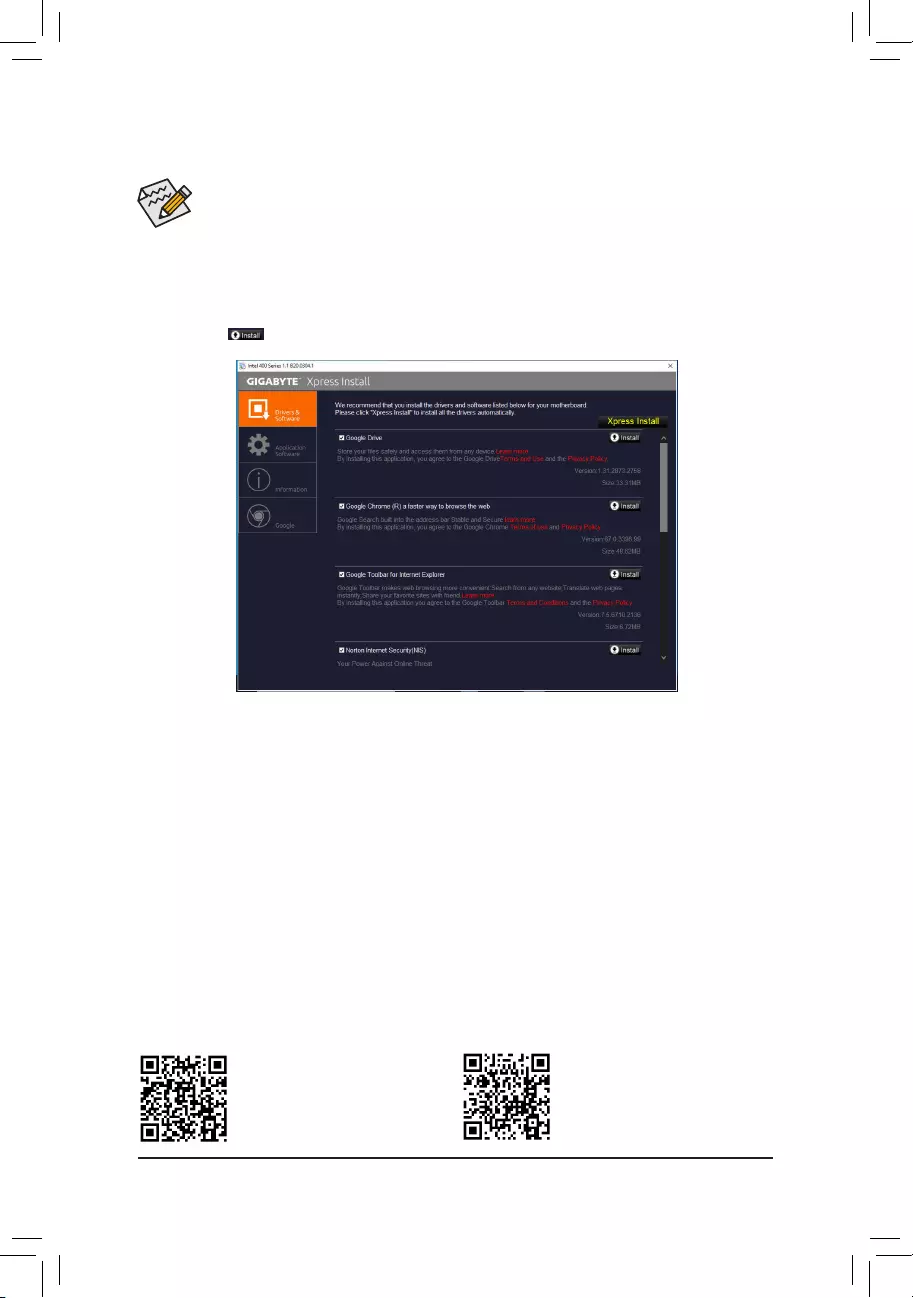
Please visit GIGABYTE’s website for
more software information.
Please visit GIGABYTE’s website for
more troubleshooting information.
•Beforeinstallingthedrivers,rstinstalltheoperatingsystem.
•After installing the operating system, insert the motherboard driver disk into your optical drive.
Clickonthemessage«Taptochoosewhathappenswiththisdisc»onthetop—rightcornerof
thescreenandselect»RunRun.exe.«(OrgotoMyComputer,double—clicktheopticaldriveand
executetheRun.exeprogram.)
«XpressInstall»willautomaticallyscanyoursystemandthenlistallofthedriversthatarerecommendedto
install. You can click the Xpress Installbuttonand«XpressInstall»willinstallalloftheselecteddrivers.Or
click the arrow icon to individually install the drivers you need.
3-3 Drivers Installation
— 42 —

Regulatory Notices
CAUTION:
Themanufacturerisnotresponsibleforanyinterferencecausedbyunauthorizedmodicationsand/oruseofunauthorizedantennas.Suchchanges
and/ormodications not expresslyapproved bythe partyresponsiblefor compliance ofthis devicecould voidtheuser’s authority tooperate the
equipment.
RF exposure statement / Antenna Use
FurtherRFexposurereductioncanbeachievediftheproductcanbekeptasfaraspossiblefromtheuserbodyorsetthedevicetoloweroutput
power if such function is available.
•Do not touch or move antenna while the unit is transmitting or receiving.
•Do not hold any component containing the radio such that the antenna is very close or touching any exposed parts of the body, especially the face
or eyes, while transmitting.
•Do not operate the radio or attempt to transmit data unless the antenna is connected; this behavior may cause damage to the radio.
United States of America, Federal Communications Commission Statement
Supplier’s Declaration of Conformity
47 CFR § 2.1077 Compliance Information
Product Name: Motherboard
Trade Name: GIGABYTE
Model Number: B460M DS3H AC/B460M DS3H
Responsible Party – U.S. Contact Information: G.B.T. Inc.
Address: 17358 Railroad street, City Of Industry, CA91748
Tel.: 1-626-854-9338
Internet contact information: https://www.gigabyte.com
FCC Compliance Statement:
This device complies with Part 15 of the FCC Rules, Subpart B, Unintentional Radiators.
Operation is subject to the following two conditions: (1) This device may not cause harmful interference, and (2) this
device must accept any interference received, including interference that may cause undesired operation.
This equipment has been tested and found to comply with the limits for
aClassBdigitaldevice,pursuant toPart15oftheFCCRules.These
limits are designed to provide reasonable protection against harmful
interference in a residential installation. This equipment generates,
uses and can radiate radio frequency energy and, if not installed
and used in accordance with manufacturer’s instructions, may cause
harmful interference to radio communications. However, there is no
guarantee that interference will not occur in a particular installation. If
this equipment does cause harmful interference to radio or television
reception, which can be determined by turning the equipment off and
on, the user is encouraged to try to correct the interference by one or
more of the following measures:
•Reorientorrelocatethereceivingantenna.
•Increase the separation between the equipment and receiver.
•Connect the equipment to an outlet on a circuit different from that to
which the receiver is connected.
•Consult the dealer or an experienced radio/TV technician for help.
Notice for 5GHz
Operationsin the 5.15-5.25GHz band are restricted toindoorusage
only.(For5GHzonly)
Canadian Department of Communications Statement
This digital apparatus does not exceed the Class B limits for radio
noiseemissionsfromdigitalapparatussetoutintheRadioInterference
RegulationsoftheCanadianDepartmentofCommunications.Thisclass
B digital apparatus complies with Canadian ICES-003.
Avis de conformité à la réglementation d’Industrie Canada
CetappareilnumériquedelaclasseBestconformeàlanormeNMB-
003 du Canada.
Canada-Industry Canada (IC) Regulatory statement
ThisdevicecomplieswithCanadianRSS-210.
ThisdevicecomplieswithIndustryCanadalicense-exemptRSS
standard(s). Operation is subject to the following two conditions: (1) this
device may not cause interference, and (2) this device must accept any
interference, including interference that may cause undesired operation
of the device.
CetappareilseconformeauxnormesCanadad’IndustriedeRSS
permis-exempt. L’utilisation est assujetti aux deux conditions suivantes:
(1) cet appareil ne peut pas causer d’interférences, et (2) cet appareil
doit accepter des interférences, y compris des interférences qui peuvent
causer desopérations non désirées de l’appareil.
Caution:WhenusingIEEE802.11awirelessLAN,thisproductis
restrictedto indoor useduetoitsoperationinthe5.15-to5.25-GHz
frequency range. Industry Canada requires this product to be used
indoorsforthefrequencyrangeof5.15GHzto5.25GHztoreducethe
potential for harmful interference to co-channel mobile satellite systems.
High power radar is allocated as the primary user of the 5.25-to 5.35-
GHzand5.65to5.85-GHzbands.Theseradarstationscancause
interference with and/or damage to this device. The maximum allowed
antenna gain for use with this device is 6dBi in order tocomply with the
E.I.R.Plimitforthe5.25-to5.35and5.725to5.85GHzfrequencyrange
inpoint-to-point operation. To comply withRF exposurerequirements
all antennas should be located at a minimum distance of 20cm, or the
minimum separation distance allowed by the module approval, from the
body of all persons.
Attention:l’utilisationd’unréseausans l IEEE802.11aestrestreinte
à une utilisation en intérieur à cause du fonctionnement dansla bande
defréquence5.15-5.25 GHz. IndustryCanada requiert quece produit
soit utilisé à l’intérieur des bâtiments pour la bande de fréquence 5.15-
5.25GHz an deréduire lespossibilités d’interférencesnuisibles aux
canaux co-existants des systèmes de transmission satellites. Les radars
de puissances ont fait l’objet d’une allocation primaire de fréquences
dansles bandes 5.25-5.35GHz et 5.65-5.85GHz. Ces stationsradar
peuvent créer des interférences avec ce produit et/ou lui être nuisible.
Le gain d’antenne maximum permissible pour une utilisation avec
ceproduit estde 6dBi an d’êtreconforme auxlimites de puissance
isotropiquerayonnéeéquivalente(P.I.R.E.)applicabledanslesbandes
5.25-5.35GHzet5.725-5.85GHzenfonctionnementpoint-à-point.Pour
seconformeraux conditions d’exposition de RF toutes les antennes
devraient être localisées à une distance minimum de 20 cm, ou la
distance de séparation minimum permise par l’approbation du module,
du corps de toutes les personnes.”
— 43 —
Radiation Exposure Statement:
Under Industry Canada regulations, this radio transmitter may only
operate using an antenna of a type and maximum (or lesser) gain
approved for the transmitter by Industry Canada. To reduce potential
radio interference to other users, the antenna type and its gain should
be so chosen that the equivalent isotropically radiated power (e.i.r.p.) is
not more than that necessary for successful communication.
Selon les règlements de Canada d’Industrie, cet émetteur de radio
peut seulement fonctionner en utilisant une antenne du typeet de gain
maximum (ou moindre) que le gainapprouvé pour l’émetteur par Canada
d’Industrie. Pour réduire lesinterférencesradio potentiellesavec les
autres utilisateurs, le type d’antenne et son gain devraient êtrechoisis de
façonàcequelapuissanceisotroperayonnéeéquivalente(P.I.R.E.)ne
soit pas supérieure à celle qui estnécessaire pour une communication
réussie.
European Union (EU) CE Declaration of Conformity
This device complies with the following directives: Electromagnetic
Compatibility Directive 2014/30/EU, Low-voltage Directive 2014/35/EU,
RadioEquipmentDirective(RED)2014/53/EU,RoHSdirective(recast)
2011/65/EU & the 2015/863 Statement.
This product has been tested and found to comply with all essential
requirements of the Directives.
European Union (EU) RoHS (recast) Directive 2011/65/EU & the
European Commission Delegated Directive (EU) 2015/863 Statement
GIGABYTEproductshavenotintendedtoaddandsafefromhazardous
substances (Cd, Pb, Hg, Cr+6, PBDE, PBB, DEHP, BBP, DBP and
DIBP). The parts and components have been carefully selected to meet
RoHSrequirement.Moreover,weatGIGABYTEarecontinuingour
efforts to develop products that do not use internationally banned toxic
chemicals.
European Union (EU) Community Waste Electrical & Electronic
Equipment (WEEE) Directive Statement
GIGABYTEwillfulllthenationallawsasinterpretedfromthe2012/19/
EU WEEE (Waste Electrical and Electronic Equipment) (recast)
directive. The WEEE Directive specifies the treatment, collection,
recycling and disposal of electric and electronic devices and their
components. Under the Directive, used equipment must be marked,
collected separately, and disposed of properly.
WEEE Symbol Statement
The symbol shown below is on the product or on its
packaging, which indicates that this product must not be
disposed of with other waste. Instead, the device should
be taken to the waste collection centers for activation of
the treatment, collection, recycling and disposal procedure.
For more information about where you can drop off your waste
equipmentforrecycling,please contact your local government ofce,
your household waste disposal service or where you purchased the
product for details of environmentally safe recycling.
End of Life Directives-Recycling
The symbol shown below is on the product or on its
packaging, which indicates that this product must not be
disposed of with other waste. Instead, the device should be
taken to the waste collection centers for activation of the
treatment, collection, recycling and disposal procedure.
Déclaration de Conformité aux Directives de l’Union européenne (UE)
Cet appareil portant la marque CE est conforme aux directives de
l’UE suivantes: directive Compatibilité Electromagnétique 2014/30/
UE,directive Basse Tension 2014/35/UE, directiveRED (équipements
radioélectriques)2014/53/UE,ladirectiveRoHSII2011/65/UE&la
déclaration 2015/863. La conformité à ces directives est évaluée sur la
base des normes européennes harmonisées applicables.
European Union (EU) CE-Konformitätserklärung
DiesesProduktemitCE-KennzeichnungerfüllenfolgendenEU-
Richtlinien:EMV-Richtlinie2014/30/EU,Niederspannungsrichtlinie
2014/30/EU,RichtlinieRED(Funkanlagen)2014/53/EU,RoHS-
Richtlinie2011/65/EUerfülltunddie2015/863Erklärung.
DieKonformitätmitdiesenRichtlinienwirdunterVerwendungder
entsprechendenStandardszurEuropäischenNormierungbeurteilt.
CE declaração de conformidade
Este produto com a marcação CE estão em conformidade com das
seguintes Diretivas UE: Diretiva Baixa Tensão 2014/35/EU; Diretiva
CEM 2014/30/EU; Diretiva de equipamentos de rádio 2014/53/EU;
DiretivaRSP2011/65/UEeadeclaração2015/863.Aconformidade
comestasdiretivasévericadautilizandoasnormaseuropeias
harmonizadas.
CE Declaración de conformidad
Este producto que llevan la marca CE cumplen con las siguientes
Directivas de la Unión Europea: Directiva EMC (2014/30/EU), Directiva
de bajo voltaje (2014/35/EU), Directiva de equipos radioeléctricos
2014/53/EU,DirectivaRoHS(recast)(2011/65/EU)ylaDeclaración
2015/863. El cumplimiento de estas directivas se evalúa mediante las
normaseuropeasarmonizadas.
Dichiarazione di conformità CE
Questo prodotto è conforme alle seguenti direttive: Direttiva
sulla compatibilità elettromagnetica 2014/30/UE, Direttiva sulle
apparecchiatureradio(RED)2014/53/UE,Direttivasullabassatensione
2014/35/UE,DirettivaRoHS(rifusione)2011/65/UEeDichiarazione
2015/863. Questo prodotto è stato testato e trovato conforme a tutti i
requisitiessenzialidelleDirettive.
Contact point for EU based customers
G.B.T. Technology Trading GmbH
Am Stadtrand 63, 22047 Hamburg, Germany
tel: +49-40-25 33 040
— 44 —
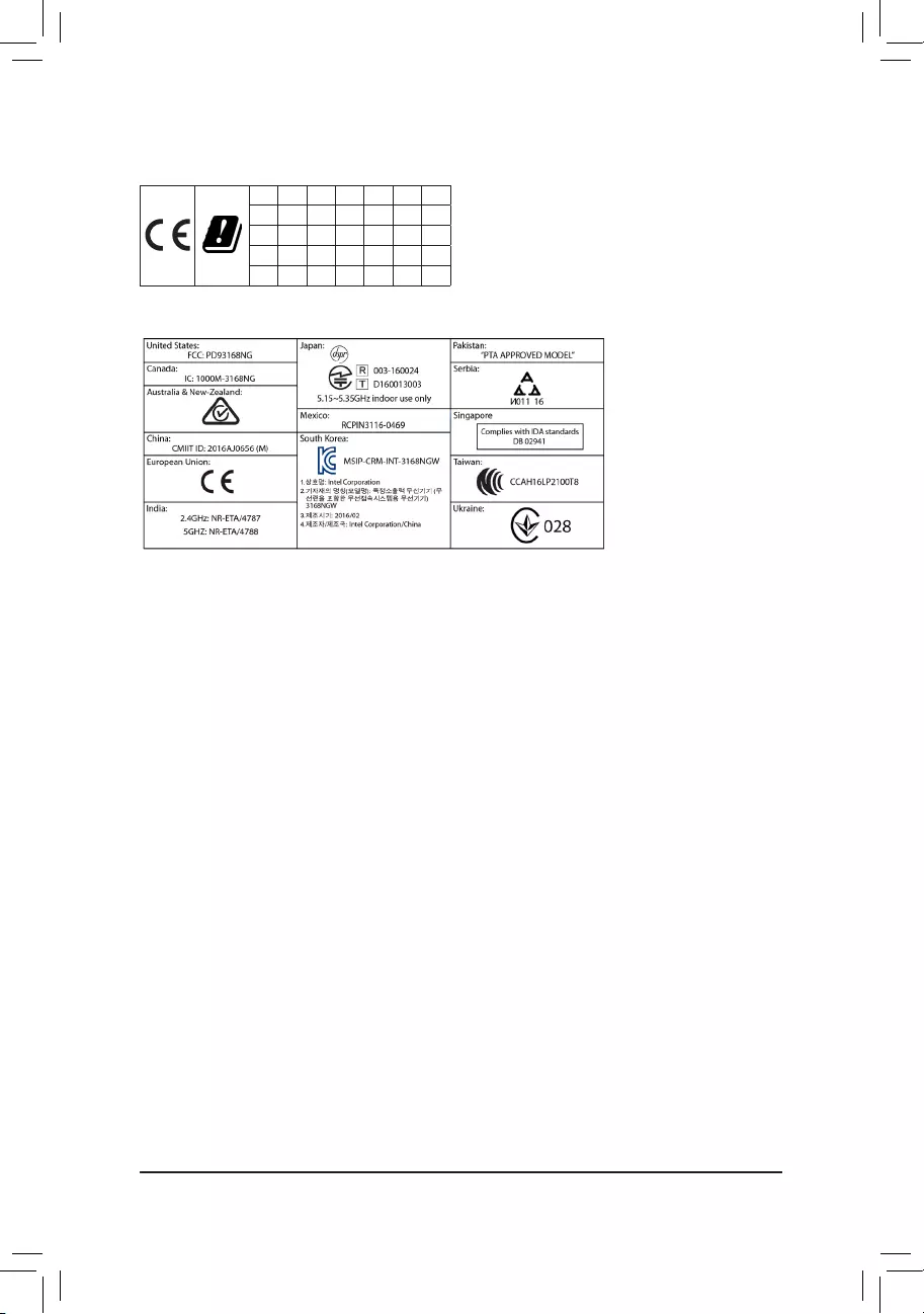
European Community Directive RED Directive Compliance Statement:
ThisequipmentissuitableforhomeandofceuseinalltheEuropeanCommunityMemberStatesandEFTAMemberStates.
Thelowband5.15-5.35GHzisforindooruseonlyforthecountrieslistedinthetablebelow:
AT BE BG CH CY CZ DE
DK EE EL ES FI FR HR
HU IE IS IT LI LT LU
LV MT NL PL PT RO SE
SI SK TR UK
Wireless module country approvals:
Wirelessmodulemodelname: 3168NGW
Wireless module manufacturer: Intel® Corporation
Korea Wireless Statement:
5.15 — 5.35GHz 대역에서의 작동은 실내로。
Japan Wireless Statement:
5.15GHz帯~5.35GHz帯: 屋内のみの使用。
Taiwan NCC Wireless Statements / 無線設備警告聲明:
低功率電波輻射性電機管理辦法
第十二條: 經型式認證合格之低功率射頻電機,非經許可,公司、商號或使用者均不得擅自變更頻率、加大功率或變更原
設計之特性及功能。
第十四條: 低功率射頻電機之使用不得影響飛航安全及干擾合法通信;經發現有干擾現象時,應立即停用,並改善至無干
擾時方得繼續使用。前項合法通信,指依電信法規定作業之無線電通信。低功率射頻電機須忍受合法通信或工
業、科學及醫療用電波輻射性電機設備之干擾。
在5.25-5.35秭赫頻帶內操作之無線資訊傳輸設備,限於室內使用。
— 45 —
Contact Us
GIGA-BYTE TECHNOLOGY CO., LTD.
Address:No.6,BaoqiangRd.,XindianDist.,NewTaipeiCity231,Taiwan
TEL: +886-2-8912-4000, FAX: +886-2-8912-4005
Tech.andNon-Tech.Support(Sales/Marketing):https://esupport.gigabyte.com
WEB address (English): https://www.gigabyte.com
WEB address (Chinese): https://www.gigabyte.com/tw
•GIGABYTE eSupport
To submit a technical or non-technical (Sales/Marketing) question, please link to:
https://esupport.gigabyte.com
— 46 —
- Manuals
- Brands
- Gigabyte Manuals
- Motherboard
- B460M DS3H V2
- User manual
-
Bookmarks
Quick Links
B460M DS3H V2
User’s Manual
Rev. 1001
For more product details, please visit GIGABYTE’s website.
To reduce the impacts on global warming, the packaging materials of this product
are recyclable and reusable. GIGABYTE works with you to protect the environment.
Related Manuals for Gigabyte B460M DS3H V2
Summary of Contents for Gigabyte B460M DS3H V2
-
Page 1
B460M DS3H V2 User’s Manual Rev. 1001 For more product details, please visit GIGABYTE’s website. To reduce the impacts on global warming, the packaging materials of this product are recyclable and reusable. GIGABYTE works with you to protect the environment. -
Page 2
Information in this manual is protected by copyright laws and is the property of GIGABYTE. Changes to the specifications and features in this manual may be made by GIGABYTE without prior notice. No part of this manual may be reproduced, copied, translated, transmitted, or published in any form or by any means without GIGABYTE’s prior written permission. -
Page 3
Table of Contents B460M DS3H V2 Motherboard Layout …………….4 Chapter 1 Hardware Installation ………………5 Installation Precautions ………………5 Product Specifications ………………6 Installing the CPU ……………….. 9 Installing the Memory ………………9 Installing an Expansion Card …………….. 10 Back Panel Connectors ……………… 10 Internal Connectors ……………… -
Page 4
B460M DS3H V2 Motherboard Layout KB_MS_USB ATX_12V_2X4 CPU_FAN SYS_FAN1 LGA1200 U32_LAN Intel ® GbE LAN AUDIO PCIEX16 B460M DS3H V2 ® PCIEX1_1 Super I/O M_BIOS Intel H470 ® PCIEX1_2 CODEC PCIEX4 CLR_CMOS SPI_TPM QFLED QFLASH_PLUS LED_C1 F_PANEL F_AUDIO F_USB1 D_LED1… -
Page 5
Chapter 1 Hardware Installation Installation Precautions The motherboard contains numerous delicate electronic circuits and components which can become damaged as a result of electrostatic discharge (ESD). Prior to installation, carefully read the user’s manual and follow these procedures: • Prior to installation, make sure the chassis is suitable for the motherboard. •… -
Page 6
Support for non-ECC Un-buffered DIMM 1Rx8/2Rx8/1Rx16 memory modules Š Support for Extreme Memory Profile (XMP) memory modules Š (Go to GIGABYTE’s website for the latest supported memory speeds and memory modules.) Onboard Integrated Graphics Processor-Intel HD Graphics support: ®… -
Page 7
Storage Interface Š 1 x M.2 connector (Socket 3, M key, type 2242/2260/2280/22110 PCIe x4/x2 SSD support) (M2Q_SB) 4 x SATA 6Gb/s connectors Š Support for RAID 0, RAID 1, RAID 5, and RAID 10 Š Intel Optane Memory Ready ®… -
Page 8
System Form Factor Micro ATX Form Factor; 24.4cm x 24.4cm Š * GIGABYTE reserves the right to make any changes to the product specifications and product-related information without prior notice. Please visit the SupportUtility List Please visit GIGABYTE’s website for support lists of CPU, memory page on GIGABYTE’s website to modules, SSDs, and M.2 devices. -
Page 9
• Make sure that the motherboard supports the memory. It is recommended that memory of the same capacity, brand, speed, and chips be used. (Go to GIGABYTE’s website for the latest supported memory speeds and memory modules.) • Always turn off the computer and unplug the power cord from the power outlet before installing the memory to prevent hardware damage. -
Page 10
The four memory sockets are divided into two channels and each channel has two memory sockets as following: Channel A: DDR4_A1, DDR4_A2 Channel B: DDR4_B1, DDR4_B2 Recommanded Dual Channel Memory Configuration: DDR4_A1 DDR4_A2 DDR4_B1 DDR4_B2 2 Modules DS/SS DS/SS 4 Modules DS/SS DS/SS DS/SS… -
Page 11
> Playback Device to change the default setting first. Please visit GIGABYTE’s website for details on configuring the audio software. (Note) To enable the Q-Flash Plus function please visit the «Unique Features» webpage of GIGABYTE’s website. — 11 -… -
Page 12
Internal Connectors 11 14 ATX_12V_2X4 F_PANEL F_AUDIO CPU_FAN F_U32 SYS_FAN1 F_USB1/F_USB2 D_LED1 LED_C1 SPI_TPM QFLASH_PLUS THB_C1/THB_C2 SATA3 2/3/4/5 CLR_CMOS M2Q_SB Read the following guidelines before connecting external devices: • First make sure your devices are compliant with the connectors you wish to connect. •… -
Page 13
1/2) ATX_12V_2X4/ATX (2×4 12V Power Connector and 2×12 Main Power Connector) With the use of the power connector, the power supply can supply enough stable power to all the components on the motherboard. Before connecting the power connector, first make sure the power supply is turned off and all devices are properly installed. -
Page 14
LED strip. For how to turn on/off the lights of the LED strip please visit the «Unique Features» webpage of GIGABYTE’s website. Before installing the devices, be sure to turn off the devices and your computer. Unplug the power cord from the power outlet to prevent damage to the devices. -
Page 15
BIOS flashing is complete. QFLED QFLASH_PLUS For how to use Q-Flash Plus please visit the «Unique Features» webpage of GIGABYTE’s website. SATA3 2/3/4/5 (SATA 6Gb/s Connectors) The SATA connectors conform to SATA 6Gb/s standard and are compatible with SATA 3Gb/s and SATA 1.5Gb/s standard.
 -
Page 16
9) M2Q_SB (M.2 Socket 3 Connector) (Note) The M.2 connectors support M.2 PCIe SSDs and RAID configuration.Please note that an M.2 PCIe SSD cannot be used to create a RAID set either with an M.2 SATA SSD or a SATA hard drive. To create a RAID array with an M.2 PCIe SSD, you must set up the configuration in UEFI BIOS mode. -
Page 17
11) F_AUDIO (Front Panel Audio Header) The front panel audio header supports High Definition audio (HD). You may connect your chassis front panel audio module to this header. Make sure the wire assignments of the module connector match the pin assignments of the motherboard header. Incorrect connection between the module connector and the motherboard header will make the device unable to work or even damage it. -
Page 18
Power (3.3V) No Pin Data Input S F_ S F_ 16) THB_C1/THB_C2 (Thunderbolt Add-in Card Connectors) ™ The connectors are used to connect to a GIGABYTE Thunderbolt add-in card. ™ Supports a Thunderbolt add-in card. ™ THB_C2 THB_C1 F_USB30 3… -
Page 19
17) CLR_CMOS (Clear CMOS Jumper) Use this jumper to clear the BIOS configuration and reset the CMOS values to factory defaults. To clear the CMOS values, use a metal object like a screwdriver to touch the two pins for a few seconds. Open: Normal Short: Clear CMOS Values •… -
Page 20
To access the BIOS Setup program, press the <Delete> key during the POST when the power is turned on. To upgrade the BIOS, use either the GIGABYTE Q-Flash or @BIOS utility. Q-Flash allows the user to quickly and easily upgrade or back up BIOS without entering the operating system. -
Page 21
The Main Menu System Setup Menus Time Configuration Items Hardware Information Option Description Current Settings Quick Access Bar allows you to quickly move to the General Help, Easy Mode, Smart Fan 5, or Q-Flash screen. Advanced Mode Function Keys <f><g> Move the selection bar to select a setup menu <h><i>… -
Page 22
Favorites (F11) Set your frequently used options as your favorites and use the <F11> key to quickly switch to the page where all of your favorite options are located. To add or remove a favorite option, go to its original page and press <Insert>… -
Page 23
Tweaker Whether the system will work stably with the overclock/overvoltage settings you made is dependent on your overall system configurations. Incorrectly doing overclock/overvoltage may result in damage to CPU, chipset, or memory and reduce the useful life of these components. This page is for advanced users only and we recommend you not to alter the default settings to prevent system instability or other unexpected results. -
Page 24
& Intel(R) Speed Shift Technology (Intel Speed Shift Technology) ® (Note) Enables or disables Intel Speed Shift Technology. Enabling this feature allows the processor to ramp up ® its operating frequency more quickly and then improves the system responsiveness. (Default: Enabled) &… -
Page 25
d C-States Control & CPU Enhanced Halt (C1E) Enables or disables Intel CPU Enhanced Halt (C1E) function, a CPU power-saving function in system halt state. ® When enabled, the CPU core frequency and voltage will be reduced during system halt state to decrease power consumption. -
Page 26
& Core Current Limit (Amps) Allows you to set a current limit for CPU Turbo mode. When the CPU current exceeds the specified current limit, the CPU will automatically reduce the core frequency in order to reduce the current. Auto sets the power limit according to the CPU specifications. -
Page 27
& Memory Enhancement Settings Provides several memory performance enhancement settings: Auto, Relax OC, Enhanced Stability, Normal, Enhanced Performance, High Frequency, High Density, and DDR-4500+. (Default: Auto) & Memory Channel Detection Message Allows you to determine whether to show an alert message when the memory is not installed in the optimal memory channel. -
Page 28
Settings ƒ Platform Power & Platform Power Management Enables or disables the Active State Power Management function (ASPM). (Default: Disabled) & PEG ASPM Allows you to configure the ASPM mode for the device connected to the CPU PEG bus. This item is configurable only when Platform Power Management is set to Enabled. -
Page 29
& ErP Determines whether to let the system consume least power in S5 (shutdown) state. (Default: Disabled) Note: When this item is set to Enabled, the following functions will become unavailable: Resume by Alarm, power on by mouse, and power on by keyboard. &… -
Page 30
& Audio Controller Enables or disables the onboard audio function. (Default: Enabled) If you wish to install a 3rd party add-in audio card instead of using the onboard audio, set this item to Disabled. & Above 4G Decoding Enables or disables 64-bit capable devices to be decoded in above 4 GB address space (only if your system supports 64-bit PCI decoding). -
Page 31
& PXE boot wait time Allows you to configure how long to wait before you can press <Esc> to abort the PXE boot. This item is configurable only when Network Stack is enabled. (Default: 0) & Media detect count Allows you to set the number of times to check the presence of media. This item is configurable only when Network Stack is enabled. -
Page 32
& Intel Platform Trust Technology (PTT) Enables or disables Intel PTT Technology. (Default: Disabled) ® & Software Guard Extensions (SGX) Enables or disables the Intel Software Guard Extensions technology. This feature allows legal software ® to operate in a safe environment and protects the software against attacks from malicious software. The Software Controlled option allows you to enable or disable this feature with an Intel-provided application. -
Page 33
& Fan Control Mode Lets the BIOS automatically detect the type of fan installed and sets the optimal control Auto mode. (Default) Voltage mode is recommended for a 3-pin fan. Voltage PWM mode is recommended for a 4-pin fan. PWM &… -
Page 34
System Info. This section provides information on your motherboard model and BIOS version. You can also select the default language used by the BIOS and manually set the system time. & Access Level Displays the current access level depending on the type of password protection used. (If no password is set, the default will display as Administrator.) The Administrator level allows you to make changes to all BIOS settings;… -
Page 35
System (Default) & Full Screen LOGO Show Allows you to determine whether to display the GIGABYTE Logo at system startup. Disabled skips the GIGABYTE Logo when the system starts up. (Default: Enabled) & Boot Option Priorities Specifies the overall boot order from the available devices. Removable storage devices that support GPT format will be prefixed with «UEFI:»… -
Page 36
& VGA Support Allows you to select which type of operating system to boot. Enables legacy option ROM only. Auto EFI Driver Enables EFI option ROM. (Default) This item is configurable only when Fast Boot is set to Enabled or Ultra Fast. &… -
Page 37
& Other PCI devices Allows you to select whether to enable the UEFI or Legacy option ROM for the PCI device controller other than the LAN, storage device, and graphics controllers. Do not launch Disables option ROM. Enables UEFI option ROM only. (Default) UEFI Enables legacy option ROM only. -
Page 38
Save & Exit & Save & Exit Setup Press <Enter> on this item and select Yes. This saves the changes to the CMOS and exits the BIOS Setup program. Select No or press <Esc> to return to the BIOS Setup Main Menu. &… -
Page 39
The actual BIOS Setup menu options you will see shall depend on the motherboard you have and the BIOS version. C-1. Using EZ RAID GIGABYTE motherboards provide you with the EZ RAID feature, allowing you to quickly configure a RAID array with simplified steps. Steps: 1. -
Page 40
RAID level, stripe block size, array name, and array capacity, etc. To exit the RAID BIOS utility, press <Esc> or select 6. Exit in MAIN MENU. Please visit GIGABYTE’s website for details on configuring a RAID array. — 40 -… -
Page 41
Install the RAID driver and operating system With the correct BIOS settings, you are ready to install the operating system. Installing the Operating System As some operating systems already include Intel RAID driver, you do not need to install separate RAID driver ®… -
Page 42
A-2: Installation in Intel RST Premium With Intel Optane System Acceleration mode If the SATA controller has been configured in Intel RST Premium With Intel Optane System Acceleration mode, please follow the steps below: 1. After system restarts, go to the BIOS Setup, make sure CSM Support under the Boot menu is disabled. 2. -
Page 43
You can click the Xpress Install button and «Xpress Install» will install all of the selected drivers. Or click the arrow icon to individually install the drivers you need. Please visit GIGABYTE’s website for more software information. Please visit GIGABYTE’s website for more troubleshooting information. — 43 -… -
Page 44
European Commission Delegated Directive (EU) 2015/863 Statement seguintes Diretivas UE: Diretiva Baixa Tensão 2014/35/EU; Diretiva CEM GIGABYTE products have not intended to add and safe from hazardous 2014/30/EU; Diretiva RSP 2011/65/UE. A conformidade com estas diretivas substances (Cd, Pb, Hg, Cr+6, PBDE, PBB, DEHP, BBP, DBP and DIBP). -
Page 45
— 45 -… -
Page 46
— 46 -… -
Page 47
— 47 -… -
Page 48
Contact Us GIGA-BYTE TECHNOLOGY CO., LTD. Address: No.6, Baoqiang Rd., Xindian Dist., New Taipei City 231, Taiwan TEL: +886-2-8912-4000, FAX: +886-2-8912-4005 Tech. and Non-Tech. Support (Sales/Marketing) : https://esupport.gigabyte.com WEB address (English): https://www.gigabyte.com WEB address (Chinese): https://www.gigabyte.com/tw GIGABYTE eSupport • To submit a technical or non-technical (Sales/Marketing) question, please link to: https://esupport.gigabyte.com…
![]()
B460M DS3H AC B460M DS3H
User’s Manual
Rev. 1003
For more product details, please visit GIGABYTE’s website.
To reduce the impacts on global warming, the packaging materials of this product are recyclable and reusable. GIGABYTE works with you to protect the environment.

Copyright
© 2020 GIGA-BYTE TECHNOLOGY CO., LTD. All rights reserved.
The trademarks mentioned in this manual are legally registered to their respective owners.
Disclaimer
Information in this manual is protected by copyright laws and is the property of GIGABYTE.
Changes to the specifications and features in this manual may be made by GIGABYTE without prior notice.
No part of this manual may be reproduced, copied, translated, transmitted, or published in
any form or by any means without GIGABYTE’s prior written permission.
In order to assist in the use of this product, carefully read the User’s Manual.
For product-related information, check on our website at: https://www.gigabyte.com
Identifying Your Motherboard Revision
The revision number on your motherboard looks like this: «REV: X.X.» For example, «REV: 1.0» means the revision of the motherboard is 1.0. Check your motherboard revision before updating motherboard BIOS, drivers, or when looking for technical information.
Example:

Table of Contents
|
B460M DS3H (AC) Motherboard Layout……………………………………………………………….. |
4 |
||
|
Chapter 1 |
Hardware Installation…………………………………………………………………………. |
5 |
|
|
1-1 |
Installation Precautions…………………………………………………………………………… |
5 |
|
|
1-2 |
Product Specifications…………………………………………………………………………….. |
6 |
|
|
1-3 |
Installing the CPU…………………………………………………………………………………… |
9 |
|
|
1-4 |
Installing the Memory……………………………………………………………………………… |
9 |
|
|
1-5 Installing an Expansion Card………………………………………………………………….. |
10 |
||
|
1-6 |
Back Panel Connectors…………………………………………………………………………. |
10 |
|
|
1-7 |
Internal Connectors………………………………………………………………………………. |
12 |
|
|
Chapter 2 |
BIOS Setup…………………………………………………………………………………….. |
20 |
|
|
2-1 |
Startup Screen……………………………………………………………………………………… |
20 |
|
|
2-2 |
The Main Menu…………………………………………………………………………………….. |
21 |
|
|
2-3 |
Favorites (F11)…………………………………………………………………………………….. |
22 |
|
|
2-4 |
Tweaker………………………………………………………………………………………………. |
23 |
|
|
2-5 |
Settings……………………………………………………………………………………………….. |
28 |
|
|
2-6 |
System Info………………………………………………………………………………………….. |
33 |
|
|
2-7 |
Boot……………………………………………………………………………………………………. |
34 |
|
|
2-8 |
Save & Exit………………………………………………………………………………………….. |
37 |
|
|
Chapter 3 |
Appendix………………………………………………………………………………………… |
38 |
|
|
3-1 Configuring a RAID Set…………………………………………………………………………. |
38 |
||
|
3-2 Installing an Intel® Optane™ Memory……………………………………………………….. |
40 |
||
|
3-3 |
Drivers Installation………………………………………………………………………………… |
42 |
|
|
Regulatory Notices………………………………………………………………………………………… |
43 |
||
|
Contact Us……………………………………………………………………………………………………. |
46 |
— 3 —

B460M DS3H (AC) Motherboard Layout
DVI VGA
|
KB_MS_USB |
||
|
ATX_12V_2X4 |
CPU_FAN |
LED_C2 |
|
SYS_FAN1 |
D_LED2 |
|
|
LGA1200 |
ATX |
|
HDMI
U32
U32_LAN
M2_WIFI
AUDIO
PCIEX16
Realtek®
GbE LAN
M2M_SB DDR4_A1 DDR4_A2 DDR4_B1 DDR4_B2
0 1 SATA3 2 3 SYS_FAN2
F_U32
B_BIOS 
 M_BIOS

|
iTE® |
BAT |
|
|
Super I/O |
PCIEX1_1 |
Intel® B460 |
|
CODEC |
PCIEX1_2 |
B460M DS3H (AC) |
SATA3 4 5 |
|
|
LED_C1 |
USB 2.0 Hub |
CLR_CMOS |
||
|
COMA |
SPI_TPM |
F_USB2 |
F_PANEL |
|
|
F_AUDIO |
COMB |
D_LED1 |
F_USB1 |
Box Contents
55 B460M DS3H AC or B460M DS3H motherboard
|
55 Motherboard driver disc |
55 |
Two SATA cables |
|
55 User’s Manual |
55 |
I/O Shield |
|
55 Two antennas |
*The box contents above are for reference only and the actual items shall depend on the product package you obtain. The box contents are subject to change without notice.
Only for the B460M DS3H.
Only for the B460M DS3H AC.
— 4 —

Chapter 1 Hardware Installation
1-1 Installation Precautions
The motherboard contains numerous delicate electronic circuits and components which can become damaged as a result of electrostatic discharge (ESD). Prior to installation, carefully read the user’s manual and follow these procedures:
•• Prior to installation, make sure the chassis is suitable for the motherboard.
•• Prior to installation, do not remove or break motherboard S/N (Serial Number) sticker or warranty sticker provided by your dealer. These stickers are required for warranty validation.
•• Always remove the AC power by unplugging the power cord from the power outlet before installing or removing the motherboard or other hardware components.
•• When connecting hardware components to the internal connectors on the motherboard, make sure they are connected tightly and securely.
•• When handling the motherboard, avoid touching any metal leads or connectors.
•• It is best to wear an electrostatic discharge (ESD) wrist strap when handling electronic components such as a motherboard, CPU or memory. If you do not have an ESD wrist strap, keep your hands dry and first touch a metal object to eliminate static electricity.
•• Prior to installing the motherboard, please have it on top of an antistatic pad or within an electrostatic shielding container.
•• Before connecting or unplugging the power supply cable from the motherboard, make sure the power supply has been turned off.
•• Before turning on the power, make sure the power supply voltage has been set according to the local voltage standard.
•• Before using the product, please verify that all cables and power connectors of your hardware components are connected.
•• To prevent damage to the motherboard, do not allow screws to come in contact with the motherboard circuit or its components.
•• Make sure there are no leftover screws or metal components placed on the motherboard or within the computer casing.
•• Do not place the computer system on an uneven surface.
•• Do not place the computer system in a high-temperature or wet environment.
•• Turning on the computer power during the installation process can lead to damage to system components as well as physical harm to the user.
•• If you are uncertain about any installation steps or have a problem related to the use of the product, please consult a certified computer technician.
•• If you use an adapter, extension power cable, or power strip, ensure to consult with its installation and/or grounding instructions.
— 5 —
|
1-2 |
Product Specifications |
||
|
CPU |
Support for 10th Generation Intel® Core™ i9 processors/Intel® Core™ i7 processors/ |
||
|
Intel® Core™ i5 processors/Intel® Core™ i3 processors/Intel® Pentium® processors/ |
|||
|
Intel® Celeron® processors in the LGA1200 package |
|||
|
(Go to GIGABYTE’s website for the latest CPU support list.) |
|||
|
L3 cache varies with CPU |
|||
|
Chipset |
Intel® B460 Express Chipset |
||
|
Memory |
Intel® Core™ i9/i7 processors: |
||
|
— Support for DDR4 2933/2666/2400/2133 MHz |
|||
|
Intel® Core™ i5/i3/Pentium®/Celeron® processors: |
|||
|
— Support for DDR4 2666/2400/2133 MHz |
|||
|
4 x DDR4 DIMM sockets supporting up to 128 GB (32 GB single DIMM capacity) |
|||
|
of system memory |
|||
|
Dual channel memory architecture |
|||
|
Support for ECC Un-buffered DIMM 1Rx8/2Rx8 memory modules (operate in |
|||
|
non-ECC mode) |
|||
|
Support for non-ECC Un-buffered DIMM 1Rx8/2Rx8/1Rx16 memory modules |
|||
|
Support for Extreme Memory Profile (XMP) memory modules |
|||
|
(Go to GIGABYTE’s website for the latest supported memory speeds and memory |
|||
|
modules.) |
|||
|
Onboard |
Integrated Graphics Processor-Intel® HD Graphics support: |
||
|
Graphics |
— 1 x D-Sub port, supporting a maximum resolution of 1920×1200@60 Hz |
—1 x DVI-D port, supporting a maximum resolution of 1920×1200@60 Hz
*The DVI-D port does not support D-Sub connection by adapter.
—1 x HDMI port, supporting a maximum resolution of 4096×2160@30 Hz
*Support for HDMI 1.4 version and HDCP 2.3.
Support for up to 3 displays at the same time Maximum shared memory of 512 MB
|
Audio |
Realtek® ALC887 codec |
|
|
High Definition Audio |
||
|
2/4/5.1/7.1-channel |
*To configure 7.1-channel audio, you need to open the audio software and select Device advanced settings > Playback Device to change the default setting first. Please visit GIGABYTE’s website for details on configuring the audio software.
|
LAN |
Realtek® GbE LAN chip (1000 Mbit/100 Mbit) |
|
|
Wireless |
Intel® Wi-Fi 3168 |
|
|
Communication |
— |
Wi-Fi 802.11a/b/g/n/ac, supporting 2.4/5 GHz Dual-Band |
|
Module |
— |
BLUETOOTH 5.0 |
|
— |
Support for 11ac 160MHz wireless standard and up to 1.73 Gbps data rate |
|
|
* Actual data rate may vary depending on environment and equipment. |
||
|
Expansion Slots |
1 x PCI Express x16 slot, running at x16 (PCIEX16) |
|
|
2 x PCI Express x1 slots |
||
|
(All of the PCI Express slots conform to PCI Express 3.0 standard.) |
Only for the B460M DS3H.
Only for the B460M DS3H AC.
— 6 —
Storage Interface 1 x M.2 connector (Socket 3, M key, type 2242/2260/2280 SATA and PCIe x4/ x2 SSD support)
6 x SATA 6Gb/s connectors
Support for RAID 0, RAID 1, RAID 5, and RAID 10
*Refer to «1-7 Internal Connectors,» for the installation notices for the M.2 and SATA connectors.
Intel® Optane™ Memory Ready
|
USB |
Chipset: |
|
|
— 6 x USB 3.2 Gen 1 ports (4 ports on the back panel, 2 ports available through |
||
|
the internal USB header) |
||
|
— 2 x USB 2.0/1.1 ports on the back panel |
||
|
Chipset+USB 2.0 Hub: |
||
|
— 4 x USB 2.0/1.1 ports available through the internal USB headers |
||
|
Internal |
1 x 24-pin ATX main power connector |
|
|
Connectors |
1 x 8-pin ATX 12V power connector |
|
|
1 x CPU fan header |
||
|
2 x system fan headers |
||
|
2 x addressable LED strip headers |
||
|
2 x RGB LED strip headers |
||
|
6 x SATA 6Gb/s connectors |
||
|
1 x M.2 Socket 3 connector |
||
|
1 x front panel header |
||
|
1 x front panel audio header |
||
|
1 x USB 3.2 Gen 1 header |
||
|
2 x USB 2.0/1.1 headers |
||
|
1 x Trusted Platform Module header (For the GC-TPM2.0 SPI/GC-TPM2.0 SPI |
||
|
2.0 module only) |
||
|
2 x serial port headers |
||
|
1 x Clear CMOS jumper |
||
|
Back Panel |
1 x PS/2 keyboard/mouse port |
|
|
Connectors |
1 x D-Sub port |
|
|
1 x DVI-D port |
||
|
1 x HDMI port |
||
|
4 x USB 3.2 Gen 1 ports |
||
|
2 x USB 2.0/1.1 ports |
||
|
1 x RJ-45 port |
||
|
2 x SMA antenna connectors (1T1R) |
||
|
3 x audio jacks |
||
|
I/O Controller |
iTE® I/O Controller Chip |
Only for the B460M DS3H.
Only for the B460M DS3H AC.
— 7 —
|
Hardware |
Voltage detection |
|||
|
Monitor |
Temperature detection |
|||
|
Fan speed detection |
||||
|
Overheating warning |
||||
|
Fan fail warning |
||||
|
Fan speed control |
||||
|
* Whether the fan speed control function is supported will depend on the fan you install. |
||||
|
BIOS |
2 x 128 Mbit flash |
|||
|
Use of licensed AMI UEFI BIOS |
||||
|
Support for DualBIOS™ |
||||
|
PnP 1.0a, DMI 2.7, WfM 2.0, SM BIOS 2.7, ACPI 5.0 |
||||
|
Unique Features |
Support for APP Center |
|||
|
* Available applications in APP Center may vary by motherboard model. Supported |
||||
|
functions of eachapplication mayalso vary depending onmotherboard specifications. |
||||
|
— |
@BIOS |
|||
|
— |
EasyTune |
|||
|
— |
Fast Boot |
|||
|
— |
Game Boost |
|||
|
— |
ON/OFF Charge |
|||
|
— |
Ambient LED |
|||
|
— |
RGB Fusion |
|||
|
— |
Smart Backup |
|||
|
— |
System Information Viewer |
|||
|
Support for Q-Flash |
||||
|
Support for Xpress Install |
||||
|
Bundled |
Norton® Internet Security (OEM version) |
|||
|
Software |
Realtek® 8118 Gaming LAN Bandwidth Control Utility |
|||
|
Operating |
Support for Windows 10 64-bit |
|||
|
System |
||||
|
Form Factor |
Micro ATX Form Factor; 24.4cm x 22.5cm |
*GIGABYTE reserves the right to make any changes to the product specifications and product-related information without prior notice.
|
Only for the B460M DS3H. |
Only for the B460M DS3H AC. |
|
|
B460M DS3H AC |
B460M DS3H |
Please visit GIGABYTE’s website for support lists of CPU, memory modules, SSDs, and M.2 devices.
Please visit the SupportUtility List page on GIGABYTE’s website to download the latest version of apps.
— 8 —
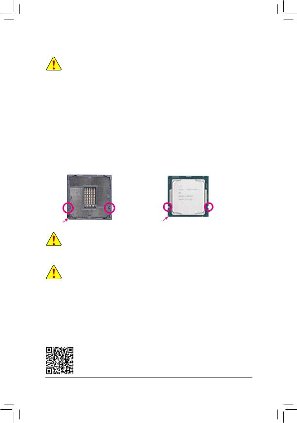
1-3 Installing the CPU
Read the following guidelines before you begin to install the CPU:
•• Make sure that the motherboard supports the CPU.
(Go to GIGABYTE’s website for the latest CPU support list.)
•• Always turn off the computer and unplug the power cord from the power outlet before installing the CPU to prevent hardware damage.
•• Locate the pin one of the CPU. The CPU cannot be inserted if oriented incorrectly. (Or you may locate the notches on both sides of the CPU and alignment keys on the CPU socket.)
•• Apply an even and thin layer of thermal grease on the surface of the CPU.
•• Do not turn on the computer if the CPU cooler is not installed, otherwise overheating and damage of the CPU may occur.
•• Set the CPU host frequency in accordance with the CPU specifications. It is not recommended that the system bus frequency be set beyond hardware specifications since it does not meet the standard requirements for the peripherals. If you wish to set the frequency beyond the standard specifications, pleasedosoaccordingtoyourhardwarespecifications includingtheCPU,graphics card, memory, hard drive, etc.
Installing the CPU
Locate the alignment keys on the motherboard CPU socket and the notches on the CPU.
|
LGA1200 CPU Socket |
LGA1200 CPU |
|
Alignment |
Alignment |
Notch |
Notch |
|
Key |
Key |
||
|
Pin One Corner of the CPU Socket |
Triangle Pin One Marking on the CPU |
Do not remove the CPU socket cover before inserting the CPU. It may pop off from the load plate automatically during the process of re-engaging the lever after you insert the CPU.
1-4 Installing the Memory
Read the following guidelines before you begin to install the memory:
•• Make sure that the motherboard supports the memory. It is recommended that memory of the same capacity, brand, speed, and chips be used.
(Go to GIGABYTE’s website for the latest supported memory speeds and memory modules.)
•• Always turn off the computer and unplug the power cord from the power outlet before installing the memory to prevent hardware damage.
•• Memory modules have a foolproof design. A memory module can be installed in only one direction. If you are unable to insert the memory, switch the direction.
Dual Channel Memory Configuration
This motherboard provides four memory sockets and supports Dual Channel Technology. After the memory is installed, the BIOS will automatically detect the specifications and capacity of the memory. Enabling Dual
Channel memory mode will double the original memory bandwidth.
Please visit GIGABYTE’s website for details on hardware installation.
— 9 —

The four memory sockets are divided into two channels and each channel has two memory sockets as following:
Channel A: DDR4_A1, DDR4_A2Channel B: DDR4_B1, DDR4_B2
Recommanded Dual Channel Memory Configuration:
|
DDR4_A1 |
DDR4_A2 |
DDR4_B1 |
DDR4_B2 |
|
|
2 Modules |
— — |
DS/SS |
— — |
DS/SS |
|
4 Modules |
DS/SS |
DS/SS |
DS/SS |
DS/SS |
(SS=Single-Sided, DS=Double-Sided, «- -«=No Memory)
Due to CPU limitations, read the following guidelines before installing the memory in Dual Channel mode.
1.Dual Channel mode cannot be enabled if only one memory module is installed.
2.When enabling Dual Channel mode with two or four memory modules, it is recommended that memory of the same capacity, brand, speed, and chips be used.
1-5 Installing an Expansion Card
Read the following guidelines before you begin to install an expansion card:
•• Make sure the motherboard supports the expansion card. Carefully read the manual that came with your expansion card.
•• Always turn off the computer and unplug the power cord from the power outlet before installing an expansion card to prevent hardware damage.
1-6 Back Panel Connectors
USB 2.0/1.1 Port
The USB port supports the USB 2.0/1.1 specification. Use this port for USB devices.
PS/2 Keyboard/Mouse Port
Use this port to connect a PS/2 mouse or keyboard.
D-Sub Port
TheD-Subportsupportsa15-pinD-Subconnectorandsupportsamaximumresolutionof1920x1200@60Hz
(the actual resolutions supported depend on the monitor being used). Connect a monitor that supports D-Sub connection to this port.
DVI-D Port (Note) 
TheDVI-DportconformstotheDVI-Dspecification andsupportsamaximumresolutionof1920x1200@60Hz
(the actual resolutions supported depend on the monitor being used). Connect a monitor that supports DVI-D connection to this port.
Only for the B460M DS3H.  Only for the B460M DS3H AC.
(Note) The DVI-D port does not support D-Sub connection by adapter.
•• When removing the cable connected to a back panel connector, first remove the cable from your device and then remove it from the motherboard.
•• When removing the cable, pull it straight out from the connector. Do not rock it side to side to prevent an electrical short inside the cable connector.
— 10 —
![]()
HDMI Port
 The HDMI port supports HDCP 2.3 and Dolby TrueHD and DTS HD Master


 Audio formats. It also supports up to 192KHz/16bit 7.1-channel LPCM audio output. You can use this port to connect your HDMI-supported monitor. The maximum supported resolution is 4096×2160@30 Hz, but the actual resolutions supported are dependent on the monitor being used.

 •• To set up a triple-display configuration, you must install motherboard drivers in the operating
system first.
•• After installing the HDMI device, make sure to set the default sound playback device to HDMI. (The item name may differ depending on your operating system.)
USB 3.2 Gen 1 Port
The USB 3.2 Gen 1 port supports the USB 3.2 Gen 1 specification and is compatible to the USB 2.0 specification. Use this port for USB devices.
RJ-45 LAN Port
The Gigabit Ethernet LAN port provides Internet connection at up to 1 Gbps data rate. The following describes the states of the LAN port LEDs.
|
Connection/ |
Connection/Speed LED: |
|||||||||||||||
|
Speed LED |
Activity LED |
|||||||||||||||
|
State |
Description |
|||||||||||||||
|
Orange |
1 Gbps data rate |
|||||||||||||||
|
Green |
100 Mbps data rate |
|||||||||||||||
|
Off |
10 Mbps data rate |
|||||||||||||||
|
LAN Port |
||||||||||||||||
SMA Antenna Connectors (1T1R)
Use this connector to connect an antenna.
Activity LED:
|
State |
Description |
|
Blinking |
Data transmission or receiving is occurring |
|
Off |
No data transmission or receiving is occurring |

 Tighten the antennas to the antenna connectors and then aim the antennas correctly for better
signal reception.
Line In/Rear Speaker Out (Blue)
The line in jack. Use this audio jack for line in devices such as an optical drive, walkman, etc.
Line Out/Front Speaker Out (Green)
The line out jack.
Mic In/Center/Subwoofer Speaker Out (Pink)
The Mic in jack.
Audio Jack Configurations:
|
Jack |
Headphone/ |
4-channel |
5.1-channel |
7.1-channel |
|
|
2-channel |
|||||
|
Line In/Rear Speaker Out |
a |
a |
a |
||
|
Line Out/Front Speaker Out |
a |
a |
a |
a |
|
|
Mic In/Center/Subwoofer Speaker Out |
a |
a |
|||
|
Front Panel Line Out/Side Speaker Out |
a |
Only for the B460M DS3H.
Please visit GIGABYTE’s website for details on configuring the audio software.
— 11 —
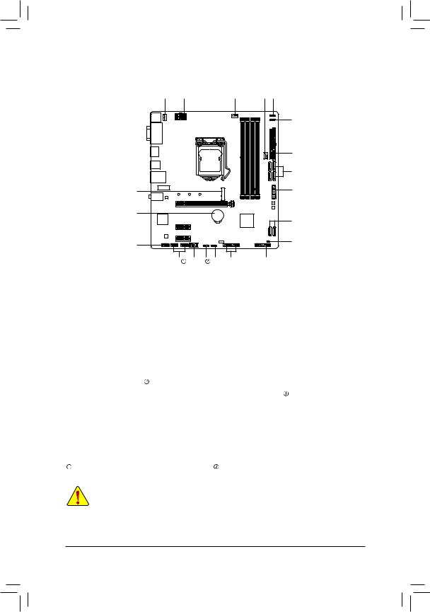
1-7 Internal Connectors
|
4 |
1 |
3 |
4 |
6 |
5
|
2 |
|||||
|
7 |
|||||
|
8 |
11 |
||||
|
15 |
7 |
||||
|
10 |
16 |
||||
|
14 |
13 |
5 |
6 |
12 |
9 |
|
1) |
ATX_12V_2X4 |
9) |
F_PANEL |
|
2) |
ATX |
10) |
F_AUDIO |
|
3) |
CPU_FAN |
11) |
F_U32 |
|
4) |
SYS_FAN1/2 |
12) |
F_USB1/F_USB2 |
|
5) |
D_LED1/D_LED2 |
13) |
SPI_TPM |
|
6) |
LED_C1/LED_C2 |
14) |
COMA/COMB |
|
7) |
SATA3 0/1/2/3/4/5 |
15) |
BAT |
|
|
M2M_SB |
16) |
CLR_CMOS |
|
Only for the B460M DS3H. |
Only for the B460M DS3H AC. |
Read the following guidelines before connecting external devices:
•• First make sure your devices are compliant with the connectors you wish to connect.
•• Before installing the devices, be sure to turn off the devices and your computer. Unplug the power cord from the power outlet to prevent damage to the devices.
•• After installing the device and before turning on the computer, make sure the device cable has been securely attached to the connector on the motherboard.
— 12 —
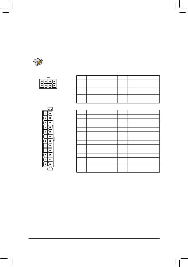
1/2) ATX_12V_2X4/ATX (2×4 12V Power Connector and 2×12 Main Power Connector)
With the use of the power connector, the power supply can supply enough stable power to all the components on the motherboard. Before connecting the power connector, first make sure the power supply is turned off and all devices are properly installed. The power connector possesses a foolproof design. Connect the power supply cable to the power connector in the correct orientation.
The 12V power connector mainly supplies power to the CPU. If the 12V power connector is not connected, the computer will not start.

 To meet expansion requirements, it is recommended that a power supply that can withstand high
  power consumption be used (500W or greater). If a power supply is used that does not provide the required power, the result can lead to an unstable or unbootable system.
|
ATX_12V_2X4: |
||||||
|
Pin No. |
Definition |
Pin No. |
Definition |
|||
|
5 |
8 |
1 |
GND (Only for 2×4-pin |
5 |
+12V (Only for 2×4-pin 12V) |
|
|
1 |
4 |
12V) |
||||
|
ATX_12V_2X4 |
2 |
GND (Only for 2×4-pin |
6 |
+12V (Only for 2×4-pin 12V) |
||
|
12V) |
||||||
|
3 |
GND |
7 |
+12V |
|||
|
4 |
GND |
8 |
+12V |
|||
|
ATX: |
||||||
|
12 |
24 |
Pin No. |
Definition |
Pin No. |
Definition |
|
|
1 |
3.3V |
13 |
3.3V |
|||
|
2 |
3.3V |
14 |
-12V |
|||
|
3 |
GND |
15 |
GND |
|||
|
4 |
+5V |
16 |
PS_ON (soft On/Off) |
|||
|
5 |
GND |
17 |
GND |
|||
|
6 |
+5V |
18 |
GND |
|||
|
7 |
GND |
19 |
GND |
|||
|
8 |
Power Good |
20 |
NC |
|||
|
9 |
5VSB (stand by +5V) |
21 |
+5V |
|||
|
10 |
+12V |
22 |
+5V |
|||
|
11 |
+12V (Only for 2×12-pin |
23 |
+5V (Only for 2×12-pin ATX) |
|||
|
1 |
13 |
ATX) |
||||
|
12 |
3.3V (Only for 2×12-pin |
24 |
GND (Only for 2×12-pin |
|||
|
ATX |
ATX) |
ATX) |
||||
— 13 —

3/4) CPU_FAN/SYS_FAN1/2 (Fan Headers)
All fan headers on this motherboard are 4-pin. Most fan headers possess a foolproof insertion design. When connecting a fan cable, be sure to connect it in the correct orientation (the black connector wire is the ground wire). The speed control function requires the use of a fan with fan speed control design. For optimum heat dissipation, it is recommended that a system fan be installed inside the chassis.
|
1 |
Pin No. |
Definition |
||||||||
|
1 |
1 |
GND |
||||||||
|
1 |
2 |
Voltage Speed Control |
||||||||
|
CPU_FAN |
SYS_FAN1 |
SYS_FAN2 |
3 |
Sense |
||||||
|
4 |
PWM Speed Control |
•• Be sure to connect fan cables to the fan headers to prevent your CPU and system from overheating. Overheating may result in damage to the CPU or the system may hang.
•• These fan headers are not configuration jumper blocks. Do not place a jumper cap on the headers.
5)D_LED1/D_LED2 (Addressable LED Strip Headers) 
The headers can be used to connect a standard 5050 addressable LED strip, with maximum power rating of 5A (5V) and maximum number of 1000 LEDs.
|
Pin No. |
Definition |
|
1 |
V (5V) |
|
2 |
Data |
|
3 |
No Pin |
|
4 |
GND |
Connect your addressable LED strip to the header. The power pin (marked with a triangle on the plug) of the LED strip must be connected to Pin 1 of the addressable LED strip header. Incorrect connection may lead to the damage of the LED strip.
6)LED_C1/LED_C2 (RGB LED Strip Headers)
The headers can be used to connect a standard 5050 RGB LED strip (12V/G/R/B), with maximum power rating of 2A (12V) and maximum length of 2m.
LED_C1 LED_C2
RGB LED Strip
1 
12V
|
Pin No. |
Definition |
|
1 |
12V |
|
2 |
G |
|
3 |
R |
|
4 |
B |
Connect your RGB LED strip to the header. The power pin
(marked with a triangle on the plug) of the LED strip must be connected to Pin 1 (12V) of this header. Incorrect connection may lead to the damage of the LED strip.
For how to turn on/off the lights of the LED strip please visit the «Unique Features» webpage of
GIGABYTE’s website.
Before installing the devices, be sure to turn off the devices and your computer. Unplug the power cord from the power outlet to prevent damage to the devices.
Only for the B460M DS3H AC.
— 14 —
 Loading…