-
Драйверы
24
-
Инструкции по эксплуатации
43
Языки:

Gigabyte GA-G31M-ES2L инструкция по эксплуатации
(72 страницы)
- Языки:Венгерский, Греческий, Испанский, Итальянский, Немецкий, Польский, Португальский, Русский, Турецкий, Французский, Чешский
-
Тип:
PDF -
Размер:
18.6 MB -
Описание:
Installation Guidebook


На NoDevice можно скачать инструкцию по эксплуатации для Gigabyte GA-G31M-ES2L. Руководство пользователя необходимо для ознакомления с правилами установки и эксплуатации Gigabyte GA-G31M-ES2L. Инструкции по использованию помогут правильно настроить Gigabyte GA-G31M-ES2L, исправить ошибки и выявить неполадки.
-
Contents
-
Table of Contents
-
Bookmarks
Quick Links
GA-G31M-ES2L
GA-G31M-ES2C
LGA775 socket motherboard for Intel
Core
processor family/
®
™
Intel
Pentium
processor family/Intel
Celeron
processor family
®
™
®
™
User’s Manual
Rev. 2401
12ME-G31MES2L-2401R
Related Manuals for Gigabyte GA-G31M-ES2L
Summary of Contents for Gigabyte GA-G31M-ES2L
-
Page 1
GA-G31M-ES2L GA-G31M-ES2C LGA775 socket motherboard for Intel Core processor family/ ® ™ Intel Pentium processor family/Intel Celeron processor family ® ™ ® ™ User’s Manual Rev. 2401 12ME-G31MES2L-2401R… -
Page 3: Identifying Your Motherboard Revision
GIGABYTE’s prior written permission. Documentation Classifications In order to assist in the use of this product, GIGABYTE provides the following types of documentations: For detailed product information, carefully read the User’s Manual.
-
Page 4: Table Of Contents
Table of Contents GA-G31M-ES2L/GA-G31M-ES2C Motherboard Layout ……….5 Chapter 1 Hardware Installation ………………6 Installation Precautions ………………. 6 1-2 Product Specifications ………………7 Installing the CPU and CPU Cooler…………..9 1-3-1 Installing the CPU ………………..9 Installing the Memory ………………10 1-4-1 Dual Channel Memory Configuration …………..10 Installing an Expansion Card ……………..
-
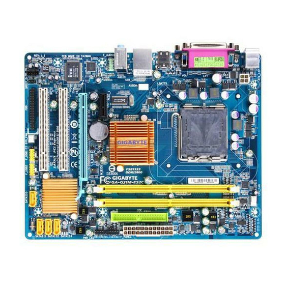
Page 5: Ga-G31M-Es2L/Ga-G31M-Es2C Motherboard Layout
GA-G31M-ES2L/GA-G31M-ES2C Motherboard Layout CPU_FAN KB_MS ATX_12V LGA775 R_USB AUDIO Intel ® F_AUDIO PCIE_1 AR8131 j AR8132 k B_BIOS M_BIOS PCIE_16 IT8718 PCI1 PCI2 CODEC Intel ICH7 ® SATAII3 SATAII2 SYS_FAN F_USB1 SATAII1 F_USB2 SATAII0 Box Contents GA-G31M-ES2L or GA-G31M-ES2C motherboard Motherboard driver disk User’s Manual One IDE cable…
-
Page 6: Chapter 1 Hardware Installation
Chapter 1 Hardware Installation Installation Precautions The motherboard contains numerous delicate electronic circuits and components which can become damaged as a result of electrostatic discharge (ESD). Prior to installation, carefully read the user’s manual and follow these procedures: • Prior to installation, do not remove or break motherboard S/N (Serial Number) sticker or warranty sticker provided by your dealer.
-
Page 7: Product Specifications
2 x 1.8V DDR2 DIMM sockets supporting up to 4 GB of system memory (Note 1) Dual channel memory architecture Support for DDR2 800/667 MHz memory modules (Go to GIGABYTE’s website for the latest supported memory speeds and memory modules.) Onboard Graphics w Integrated in the North Bridge:…
-
Page 8
Internal 1 x front panel header Connectors 1 x front panel audio header 1 x CD In connector 1 x S/PDIF Out header 2 x USB 2.0/1.1 headers 1 x power LED header 1 x chassis intrusion header Back Panel 1 x PS/2 keyboard port Connectors 1 x PS/2 mouse port… -
Page 9: Installing The Cpu And Cpu Cooler
Read the following guidelines before you begin to install the CPU: • Make sure that the motherboard supports the CPU. (Go to GIGABYTE’s website for the latest CPU support list.) • Always turn off the computer and unplug the power cord from the power outlet before installing the CPU to prevent hardware damage.
-
Page 10: Installing The Memory
• Make sure that the motherboard supports the memory. It is recommended that memory of the same capacity, brand, speed, and chips be used. (Go to GIGABYTE’s website for the latest supported memory speeds and memory modules.) • Always turn off the computer and unplug the power cord from the power outlet before installing the memory to prevent hardware damage.
-
Page 11: Back Panel Connectors
Back Panel Connectors PS/2 Keyboard and PS/2 Mouse Port Use the upper port (green) to connect a PS/2 mouse and the lower port (purple) to connect a PS/2 keyboard. Parallel Port Use the parallel port to connect devices such as a printer, scanner and etc. The parallel port is also called a printer port.
-
Page 12
Line In Jack (Blue) The default line in jack. Use this audio jack for line in devices such as an optical drive, walkman, etc. Line Out Jack (Green) The default line out jack. Use this audio jack for a headphone or 2-channel speaker. This jack can be used to connect front speakers in a 4/5.1-channel audio configuration. -
Page 13: Internal Connectors
Internal Connectors ATX_12V F_PANEL CPU_FAN F_AUDIO SYS_FAN CD_IN SPDIF_O F_USB1/F_USB2 SATAII0/1/2/3 CLR_CMOS PWR_LED Read the following guidelines before connecting external devices: • First make sure your devices are compliant with the connectors you wish to connect. • Before installing the devices, be sure to turn off the devices and your computer. Unplug the power cord from the power outlet to prevent damage to the devices.
-
Page 14
1/2) ATX_12V/ATX (2×2 12V Power Connector and 2×12 Main Power Connector) With the use of the power connector, the power supply can supply enough stable power to all the components on the motherboard. Before connecting the power connector, first make sure the power supply is turned off and all devices are properly installed. -
Page 15: Fdd (Floppy Disk Drive Connector)
3/4) CPU_FAN/SYS_FAN (Fan Headers) The motherboard has a 4-pin CPU fan header (CPU_FAN) and a 3-pin (SYS_FAN) system fan header. Most fan headers possess a foolproof insertion design. When connecting a fan cable, be sure to connect it in the correct orientation (the black connector wire is the ground wire). The motherboard supports CPU fan speed control, which requires the use of a CPU fan with fan speed control design.
-
Page 16
6) IDE (IDE Connector) The IDE connector supports up to two IDE devices such as hard drives and optical drives. Before attach- ing the IDE cable, locate the foolproof groove on the connector. If you wish to connect two IDE devices, remember to set the jumpers and the cabling according to the role of the IDE devices (for example, master or slave). (For information about configuring master/slave settings for the IDE devices, read the instructions from the device manufacturers.) -
Page 17
 PWR_LED (System Power LED Header) This header can be used to connect a system power LED on the chassis to indicate system power status. The LED is on when the system is operating. The LED keeps blinking when the system is in S1 sleep state.
 -
Page 18
10) F_PANEL (Front Panel Header) Connect the power switch, reset switch, speaker and system status indicator on the chassis front panel to this header according to the pin assignments below. Note the positive and negative pins before con- necting the cables. SPEAK- Speaker SPEAK+… -
Page 19
11) F_AUDIO (Front Panel Audio Header) The front panel audio header supports Intel High Definition audio (HD) and AC’97 audio. You may connect your chassis front panel audio module to this header. Make sure the wire assignments of the module con- nector match the pin assignments of the motherboard header. Incorrect connection between the module connector and the motherboard header will make the device unable to work or even damage it. For HD Front Panel Audio: For AC’97 Front Panel Audio: Pin No. Definition… -
Page 20
13) SPDIF_O (S/PDIF Out Header) This header supports digital S/PDIF out. Via an optional S/PDIF out cable, this header can connect to an audio device that supports digital audio in. For purchasing the optional S/PDIF out cable, please contact the local dealer. Pin No. Definition Power SPDIFO… -
Page 21: Clear Cmos Jumper
15) CLR_CMOS (Clearing CMOS Jumper) Use this jumper to clear the CMOS values (e.g. date information and BIOS configurations) and reset the CMOS values to factory defaults. To clear the CMOS values, place a jumper cap on the two pins to temporarily short the two pins or use a metal object like a screwdriver to touch the two pins for a few seconds.
-
Page 22: Chapter 2 Bios Setup
To see more advanced BIOS Setup menu options, you can press <Ctrl> + <F1> in the main menu of the BIOS Setup program. To upgrade the BIOS, use either the GIGABYTE Q-Flash or @BIOS utility. Q-Flash allows the user to quickly and easily upgrade or back up BIOS without entering the operating •…
-
Page 23: Standard Cmos Features
• If you do not find the settings you want in the Main Menu or a submenu, press <Ctrl>+<F1> to access more advanced options. • When the system is not stable as usual, select the Load Optimized Defaults item to set your system to its defaults. • The BIOS Setup menus described in this chapter are for reference only and may differ by BIOS version.
-
Page 24: Advanced Bios Features
Allows you to manually enter the specifications of the hard drive when the hard drive • Manual access mode is set to CHS. (For IDE Channel 0 Master/Slave only.) Access Mode Sets the hard drive access mode. (Default: Auto) The following fields display your hard drive specifications. If you wish to enter the parameters manually, refer to the information on the hard drive. Capacity Approximate capacity of the currently installed hard drive. Cylinder Number of cylinders.
-
Page 25: Hard Disk Boot Priority
Hard Disk Boot Priority Specifies the sequence of loading the operating system from the installed hard drives. First/Second/Third Boot Device Specifies the boot order from the available devices. Password Check Specifies whether a password is required every time the system boots, or only when you enter BIOS Setup. After configuring this item, set the password(s) under the Set Supervisor/User Password item in the BIOS Main Menu. Setup A password is only required for entering the BIOS Setup program. (Default) System A password is required for booting the system and for entering the BIOS Setup program. HDD S.M.A.R.T.
-
Page 26: Integrated Peripherals
Virtualization Technology (Note) Enables or disables Intel Virtualization Technology. Virtualization enhanced by Intel Virtualization Technology will allow a platform to run multiple operating systems and applications in independent partitions. With virtualization, one computer system can function as multiple virtual systems. (Default: Enabled) Init Display First Specifies the first initiation of the monitor display from the installed PCI graphics card, PCI Express…
-
Page 27: Usb Controller
On-Chip SATA Mode Configures the integrated SATA controller. Disabled Disables the integrated SATA controller. Lets the BIOS set SATA devices to Combined or Enhanced mode. If your on- Auto board SATA controller is automatically configured to Combined mode, you can manually re-configure it to Enhanced mode as needed. (Default) Sets all SATA devices to operate in PATA mode. Combined allows a maximum Combined of 4 ATA devices to be used simultaneously: two PATA devices plus two SATA devices.
-
Page 28: Power Management Setup
SMART LAN (LAN Cable Diagnostic Function) CMOS Setup Utility-Copyright (C) 1984-2009 Award Software SMART LAN Item Help Start detecting at Port..Menu Level Part1-2 Status = Open / Length = Part3-6 Status = Open / Length = Part4-5 Status = Open / Length = Part7-8 Status = Open / Length = …
-
Page 29
S3(STR) Enables the system to enter the ACPI S3 (Suspend to RAM) sleep state (default). In S3 sleep state, the system appears to be off and consumes less power than in the S1 state. When sig- naled by a wake-up device or event, the system resumes to its working state exactly where it was left off. Soft-Off by PWR-BTTN Configures the way to turn off the computer in MS-DOS mode using the power button. -
Page 30: Pnp/Pci Configurations
Note: To cancel the password, press <Enter> on this item. When prompted for the password, press <Enter> again without entering the password to clear the password settings. AC Back Function Determines the state of the system after the return of power from an AC power loss. Soft-Off The system stays off upon the return of the AC power.
-
Page 31: Mb Intelligent Tweaker(M.i.t.)
Current Voltage(V) Vcore/DDR18V/+3.3V/+12V Displays the current system voltages. Current CPU Temperature Displays current CPU temperature. Current CPU/SYSTEM FAN Speed (RPM) Displays current CPU/system fan speed. CPU Warning Temperature Sets the warning threshold for CPU temperature. When CPU temperature exceeds the threshold, BIOS will emit warning sound.
-
Page 32: Cpu Frequency
Robust Graphics Booster Robust Graphics Booster (R.G.B.) helps to enhance the performance of the graphics chip and memory. Auto allows the BIOS to automatically set the R.G.B. mode based on system configurations. Options are: Auto (default), Fast, Turbo. CPU Clock Ratio (Note) Allows you to alter the clock ratio for the installed CPU. The item is present only if a CPU with unlocked clock ratio is installed. CPU Frequency Displays the current operating CPU frequency.
-
Page 33: Load Fail-Safe Defaults
FSB OverVoltage Control Allows you to set the Front Side Bus voltage. Normal Supplies the FSB voltage as required. (Default) +0.1V ~ +0.3V The adjustable range is from 0.1V to 0.3V. CPU Voltage Control Allows you to set the CPU voltage. Normal sets the CPU voltage as required. The adjustable range is dependent on the CPU being installed.
-
Page 34: Set Supervisor/User Password
2-12 Set Supervisor/User Password CMOS Setup Utility-Copyright (C) 1984-2009 Award Software Standard CMOS Features Load Fail-Safe Defaults Advanced BIOS Features Load Optimized Defaults Integrated Peripherals Set Supervisor Password Power Management Setup Set User Password PnP/PCI Configurations Save &…
-
Page 35: Exit Without Saving
2-14 Exit Without Saving CMOS Setup Utility-Copyright (C) 1984-2009 Award Software Standard CMOS Features Load Fail-Safe Defaults Advanced BIOS Features Load Optimized Defaults Integrated Peripherals Set Supervisor Password Quit Without Saving (Y/N)? N Power Management Setup Set User Password …
-
Page 36: Regulatory Statements
Contravention will be prosecuted. We believe that the information contained herein was accurate in all respects at the time of printing. GIGABYTE cannot, however, assume any responsibility for errors or omissions in this text. Also note that the informa- tion in this document is subject to change without notice and should not be construed as a commitment by GIGABYTE.
-
Page 37
Finally, we suggest that you practice other environmentally friendly actions by understanding and using the energy-saving features of this product (where applicable), recycling the inner and outer packaging (including shipping containers) this product was delivered in, and by disposing of or recycling used batteries properly. With your help, we can reduce the amount of natural resources needed to produce electrical and electronic equipment, minimize the use of landfills for the disposal of «end of life» products, and generally improve our quality of life by ensuring that potentially hazardous substances are not released into the environment and… -
Page 38
WEB address (English): http://www.gigabyte.com WEB address (Chinese): http://www.gigabyte.tw You may go to the GIGABYTE website, select your language in the language list on the top right corner of the website. • GIGABYTE Global Service System To submit a technical or non-technical (Sales/Market- ing) question, please link to: http://ggts.gigabyte.com.tw… -
Page 39
— 39 — Appendix… -
Page 40
Appendix — 40 -…
 PWR_LED (System Power LED Header) This header can be used to connect a system power LED on the chassis to indicate system power status. The LED is on when the system is operating. The LED keeps blinking when the system is in S1 sleep state.
 Посмотреть инструкция для Gigabyte GA-G31M-ES2L бесплатно. Руководство относится к категории материнские платы, 15 человек(а) дали ему среднюю оценку 8.5. Руководство доступно на следующих языках: английский. У вас есть вопрос о Gigabyte GA-G31M-ES2L или вам нужна помощь? Задайте свой вопрос здесь
Не можете найти ответ на свой вопрос в руководстве? Вы можете найти ответ на свой вопрос ниже, в разделе часто задаваемых вопросов о Gigabyte GA-G31M-ES2L.
Какая ширина Gigabyte GA-G31M-ES2L?
Какая толщина Gigabyte GA-G31M-ES2L?
Инструкция Gigabyte GA-G31M-ES2L доступно в русский?
Не нашли свой вопрос? Задайте свой вопрос здесь
На этой странице вы можете совершенно бесплатно скачать Руководство по эксплуатации GIGABYTE GA-G31M-ES2L (rev. 2.4).
У документа PDF Руководство по эксплуатации 40 страниц, а его размер составляет 9.41 Mb.
Читать онлайн Материнские платы GIGABYTE GA-G31M-ES2L (rev. 2.4) Руководство по эксплуатации

Скачать файл PDF «GIGABYTE GA-G31M-ES2L (rev. 2.4) Руководство по эксплуатации» (9.41 Mb)
Популярность:
7673 просмотры
Подсчет страниц:
40 страницы
Тип файла:
Размер файла:
9.41 Mb
Прочие инструкции GIGABYTE GA-G31M-ES2L (rev. 2.4)

Прочие инструкции GIGABYTE Материнские платы


Прочие инструкции GIGABYTE


-
Gigabyte GA-G31M-ES2L — page 1
GA-G31M-ES2L GA-G31M-ES2C LGA775 socket motherboard for Intel ® Core ™ processor family/ Intel ® Pentium ™ processor family/Intel ® Celeron ™ processor family User’s Manual Rev . 2401 12M E- G 31ME S2 L — 24 01R …
-
Gigabyte GA-G31M-ES2L — page 2
Motherboard GA-G31M-ES2L GA-G31M-ES2C May 20, 2010 May 20, 2010 Motherboard GA-G31M-ES2L/GA-G31M-ES2C …
-
Gigabyte GA-G31M-ES2L — page 3
Copyright © 2010 GIGA-BYTE TECHNOLOGY CO., L TD. All rights reserved. The trademarks mentioned in this manual are legally registered to their respective owners. Disclaimer Information in this manual is protected by copyright laws and is the property of GIGABYTE. Changes to the specifications and features in this manual may be made by GIGABYTE with …
-
Gigabyte GA-G31M-ES2L — page 4
— 4 — T able of Contents GA — G3 1M- ES2L /GA- G31 M — ES2C Motherb oard Layout …………………………………………. 5 Chapter 1 Hardware Inst allation …………………………………………………………………………. 6 1- 1 Inst allatio n Prec autio ns ……………………………………………………… …
-
Gigabyte GA-G31M-ES2L — page 5
— 5 — GA- G3 1 M — ES2L/GA- G3 1 M — ES 2C Mother board Lay out KB_MS CPU_F AN LGA775 A TX GA-G31M-ES2L/GA-G31M-ES2C CD_IN F_AUDIO AUDIO B_BIOS PCIE_1 CI DDRII2 DDRII1 BA T F_P ANEL A TX_12V Intel ® G31 Intel ® ICH7 SA T AII1 SA T AII3 SA T AII0 SA T AII2 PCI1 CODEC IDE CLR_CMOS M_BIOS COMA VGA USB PCIE_16 SPDIF_O F_USB1 F_USB2 SYS_F AN FDD AR813 …
-
Gigabyte GA-G31M-ES2L — page 6
Hardware Installation — 6 — 1- 1 Installation Pr ec autions Th e mo the rbo ar d co nta ins nume ro us d eli cat e e lec tro nic circ ui ts a nd c omp on ent s wh ic h ca n become damaged as a result of electrostatic discharge (ESD). Prior to installation, carefully read the user’s manual and follow these procedures: • Prio r to ins talla …
-
Gigabyte GA-G31M-ES2L — page 7
— 7 — Hardware Installation 1- 2 Product Specications j Only for GA-G31M-ES2L. k Only for GA-G31M-ES2C. CPU w Support for an Intel ® Core ™ 2 Extreme processor/Intel ® Core ™ 2 Quad processor/ I n t e l ® Core ™ 2 Duo processor/Intel ® Pentium ® processor/Intel ® Celeron ® processor in the LGA 775 package (Go to GIGABYTE’s webs …
-
Gigabyte GA-G31M-ES2L — page 8
Hardware Installation — 8 — Internal w 1 x front panel header Connectors w 1 x front panel audio header w 1 x CD In connector w 1 x S/PDIF Out header w 2 x USB 2.0/1.1 headers w 1 x power LED header w 1 x chassis intrusion header Back Panel w 1 x PS/2 keyboard port Connectors w 1 x PS/2 mouse port w 1 x parallel port …
-
Gigabyte GA-G31M-ES2L — page 9
— 9 — Hardware Installation (Note 1) Based on standard PC architecture, a certain amount of memory is reserved for system usage and therefore the actual memory size is less th an the stated amount. For example, 4 GB of memory size will instead be shown as 3.xx GB during system startup. (Note2) T ocongure7.1-channelaudio,you? …
-
Gigabyte GA-G31M-ES2L — page 10
Hardware Installation — 10 — 1- 4 Inst alling the Memor y Read the following guidelines before you begin to install the memory: • Make sure that the motherboard supports the memory . It is recommended that memory of the same capacity , brand, speed, and chips be used. (Go to GIGABYTE’s website for the latest supported memory speeds and memor …
-
Gigabyte GA-G31M-ES2L — page 11
— 1 1 — Hardware Installation 1-6 Back Panel Connectors PS/2 Keyboard and PS/2 Mouse Port Use the uppe r p ort (green) to c onnect a PS/2 mo use and the lower p ort (purple) t o c onnect a PS/2 keyboard. Parallel Port Use the parallel port to connect devices su ch as a printer , scanner and etc. The parallel port is als o called a printer port. Ser …
-
Gigabyte GA-G31M-ES2L — page 12
Hardware Installation — 12 — Line In Jack (Blue) The default line in jack. Use this audio jack for line in devices such as an optical drive, walkman, etc. Line Out Jack (Green) The default line out jack. Use this audio jack for a headphone or 2-channel speaker. This jack can be usedtoconnectfrontspeakersina4/5.1-channelaudio …
-
Gigabyte GA-G31M-ES2L — page 13
— 13 — Hardware Installation 1- 7 Internal Connectors Read the following guidelines before connecting external devices: • First make sure your devices are compliant with the connectors you wish to connect. • Bef ore inst allin g the dev ices, b e s ure to tu rn off the de vices a nd your co mpute r . Unp lug the power cord from the power …
-
Gigabyte GA-G31M-ES2L — page 14
Hardware Installation — 14 — A TX_12V: A TX_12V 1 3 2 4 DEBUG PO RT G.QBOFM 13 1 24 12 A TX A TX: PinNo. Denition 13 3.3V 14 -12V 15 GND 16 PS_ON (soft On/Off) 17 GND 18 GND 19 GND 20 -5V 21 +5V 22 +5V 23 +5V (Only for 2×12-pi n A TX) 24 GND (On ly f or 2x 12-p in A TX) PinNo. Denition 1 3.3V 2 3.3V 3 GND 4 +5V 5 GND 6 +5V 7 GND 8 …
-
Gigabyte GA-G31M-ES2L — page 15
— 15 — Hardware Installation 3/4) CPU_F AN/SYS_F AN (Fan Headers) The motherboa rd has a 4-pin CPU fan header (CPU_F AN) and a 3-pin (SYS_F AN) system fan header . Most fan headers possess a foolproof insertion design. When connecting a fan cable, be sure to connect it in the correct orientation (the black connector wire is the ground wire). The mo …
-
Gigabyte GA-G31M-ES2L — page 16
Hardware Installation — 16 — 6) IDE (IDE Connector) The IDE connector supports up to two IDE devices such as hard drives and optical drives. Before attach- ing the IDE cable, locate the foolproof groove on the connector . If you wish to connect two IDE devices, remember to set the jum pers and the cabling accordin g t o th e r ole of the IDE device …
-
Gigabyte GA-G31M-ES2L — page 17
— 17 — Hardware Installation
PWR_LED (System Power LED Header) This he ader can b e used to co nnect a sy stem pow er LED on th e chassi s to indic ate syst em power status. The LED is on when the system is operating. The LED keeps blinking when the system is in S1 sleep state. The LED is off when the system is in S3/S4 sleep state or powered of … -
Gigabyte GA-G31M-ES2L — page 18
Hardware Installation — 18 — 10) F_P ANEL (Front Panel Header) Connect the power switch, reset switch, speaker and system status indicator on the chassis front panel to this header according to the pin assignments below. Note the positive and negative pins before con- necting the cables. • PW (Power Switch): Connects to the power …
-
Gigabyte GA-G31M-ES2L — page 19
— 19 — Hardware Installation 1 1) F_AUDIO (Front Panel Audio Header) ThefrontpanelaudioheadersupportsIn telHighDenitionaudio(HD)and AC’97audio.Y oum ayconnect your chassis front panel audio module to this header . Make sure the wire assignments of the module con — nector match the pin a …
-
Gigabyte GA-G31M-ES2L — page 20
Hardware Installation — 20 — 13) SPDIF_O (S/PDIF Out Header) This header supports digital S/PDIF out. Via an optional S/PDIF out cable, this header can connect to an audio device that supports digital audio in. For purchasing the optional S/PDIF out cable, please contact the local dealer . PinNo. Denition 1 Power 2 SPDIFO 3 GND 1 14) F_USB …
-
Gigabyte GA-G31M-ES2L — page 21
— 21 — Hardware Installation 15) CLR_CMOS (Clearing CMOS Jumper) Use this jumper to clear the CMOS values (e.g. date information and BIOS congurations) and reset the CMOS values to factory defaults. T o clear the CMOS values, place a jumper cap on the two pins to temporarily short the two pins …
-
Gigabyte GA-G31M-ES2L — page 22
BIOS Setup — 22 — T o access the BIOS Setup program, press the <Delete> key during the POST when the power is turned on. T o see more advanced BIOS Setup menu options, you can press <Ctrl> + <F1> in the main menu of the BIOS Setup program. T o upgrade the BIOS, use either the GIGABYTE Q-Flash or @BIOS utility . • Q-Flash allows …
-
Gigabyte GA-G31M-ES2L — page 23
— 23 — BIOS Setup • If you do not nd the settings you want in the Main Menu or a submenu, press <Ctrl>+<F1> to access more advanced options. • When the system is not stable as usual, select the Load Optimized Defaults item to set your system to its defaults. • The BIO …
-
Gigabyte GA-G31M-ES2L — page 24
BIOS Setup — 24 — • Manual Allowsyoutomanuallyenterthespecicationsoftheharddrivewhentheharddrive access mode is set to CHS . (For IDE Channel 0 Master/Slave only .) Access Mode Sets the hard drive access mode. (Default: Auto) The followingelds display your hard d …
-
Gigabyte GA-G31M-ES2L — page 25
— 25 — BIOS Setup Hard Disk Boot Priority Speciesthesequenceofloadingtheoperatingsystemfromtheinstalledharddrives. First/Second/Third Boot Device Speciesthebootorderfromtheavailabledevices. Password Check Species whether a password is required ever …
-
Gigabyte GA-G31M-ES2L — page 26
BIOS Setup — 26 — Virtualization T echnology (Note) En ab l es o r di sa b le s In te l Vi rt ua l iz at io n T e ch no l og y . Vi rt u al iz at io n e nh an ce d b y I n te l Vi rt ua li za t io n T ec hno log y w ill a llo w a pla tfor m to ru n mul tipl e ope rat ing s yste ms an d app lic atio ns in i nde pend ent partitions. With virtualizati …
-
Gigabyte GA-G31M-ES2L — page 27
— 27 — BIOS Setup On-Chip SA T A Mode CongurestheintegratedSA T Acontroller . Disabled Disables the integrated SA T A controller . Auto Lets the BIOS set SA T A devices to Combined or Enhanced mode. If your on- board SA T Acontroller is automatically congured to Combined mode, you can manua …
-
Gigabyte GA-G31M-ES2L — page 28
BIOS Setup — 28 — Onboard LAN Boot ROM Allows you to decide whether to activate the boot ROM integrated with the onboard LAN chip. (Default: Disabled) Onboard Serial Port 1 Enables or disables the rst serial port and species its base I/O address and corresponding interrupt. Options are: Auto …
-
Gigabyte GA-G31M-ES2L — page 29
— 29 — BIOS Setup (Note) Supported on Windows 7/Vista operating system only . S3(STR) Enables the system to enter the ACPI S3 (Suspend to RAM) sleep state (default). In S3 sleep state, the system appears to be off and consumes less power than in the S1 state. When sig — naled by a wake-up device or event, the system resumes to its working state exa …
-
Gigabyte GA-G31M-ES2L — page 30
BIOS Setup — 30 — Note: T o can cel the pas sword, pr ess <Ente r> on this it em. When pr ompted fo r the passw ord, pres s <Enter> again without entering the password to clear the password settings. AC Back Function Determines the state of the system after the return of power from an AC power loss. Soft-Off The system stays off upon th …
-
Gigabyte GA-G31M-ES2L — page 31
— 31 — BIOS Setup Current V oltage(V) Vcore/DDR18V/+3.3V/+12V Displays the current system voltages. Current CPU T emperature Displays current CPU temperature. Current CPU/SYSTEM F AN Speed (RPM) Displays current CPU/system fan speed. CPU Warning T emperature Se ts t he w ar ni ng t hr es ho ld f or C PU te mp er at ur e. W he n CP U te mp er at ur …
-
Gigabyte GA-G31M-ES2L — page 32
BIOS Setup — 32 — Robust Graphics Booster Robust Graphics Booster (R.G.B.) helps to enhance the performance of the graphics chip and memory . Auto allows the BIOS to automatically set the R.G.B. mode based on system congurations. Options are: Auto (default), Fast, T urbo. CPU Clock Ratio (Note) Allow …
-
Gigabyte GA-G31M-ES2L — page 33
— 33 — BIOS Setup FSB OverV oltage Control Allows you to set the Front Side Bus voltage. Normal Supplies the FSB voltage as required. (Default) +0.1V ~ +0.3V The adjustable range is from 0.1V to 0.3V . CPU V oltage Control Allows you to set the CPU voltage. Normal sets the CPU voltage as required. The adjustable range is dependent on the CPU being …
-
Gigabyte GA-G31M-ES2L — page 34
BIOS Setup — 34 — Press <Enter> on this item and type the password with up to 8 characters and then press <Enter>. Y ou will berequestedtoconrmthepassword.T ypethepasswordagainandpress<Enter>. The BIOS Setup program allows you to specify two separate passwords: Supervisor Password- When a …
-
Gigabyte GA-G31M-ES2L — page 35
— 35 — BIOS Setup Press <Enter> on this item and press the <Y> key . This exits the BIOS Setup without saving the changes made in BIOS Setup to the CMOS. Press <N> or <Esc> to return to the BIOS Setup Main Menu. 2-14 Exit Without Saving CMOS Setup Utility-Copyright (C) 1984-2009 A ward Software Abandon all Data Standard …
-
Gigabyte GA-G31M-ES2L — page 36
Appendix — 36 — Regulatory Statements Regulatory Notices This document must not be copied without ou r wri tten permission, and the contents there of must not be imparted to a third party nor be used for any unauthorized purpose. Contravention will be prosecuted. We believe that the information contained herein was accurate in all respects at the t …
-
Gigabyte GA-G31M-ES2L — page 37
— 37 — Appendix Finally , we suggest that you practice other environmentally friendly actions by understanding and using the energy-saving features of this product (where applicable), recycling the inner and outer packaging (including shipping containers) this product was delivered in, and by disposing of or recycling used batteries properly . With …
-
Gigabyte GA-G31M-ES2L — page 38
Appendix — 38 — Contact Us GIGA-BYTE TECHNOLOGY CO., L TD. Address: No.6, Bau Chiang Road, Hsin-Tien, T aipei 231, T aiwan TEL: +886-2-8912-4000, F AX: +886-2-8912-4003 T ech. and Non-T ech. Support (Sales/Marketing) : http://ggts.gigabyte.com.tw WEB address (English): http://www .gigabyte.com WEB address (Chinese): http://www .gigabyte.tw Y ou may …
-
Gigabyte GA-G31M-ES2L — page 39
— 39 — Appendix …
-
Gigabyte GA-G31M-ES2L — page 40
Appendix — 40 — …