-
Contents
-
Table of Contents
-
Troubleshooting
-
Bookmarks
Quick Links
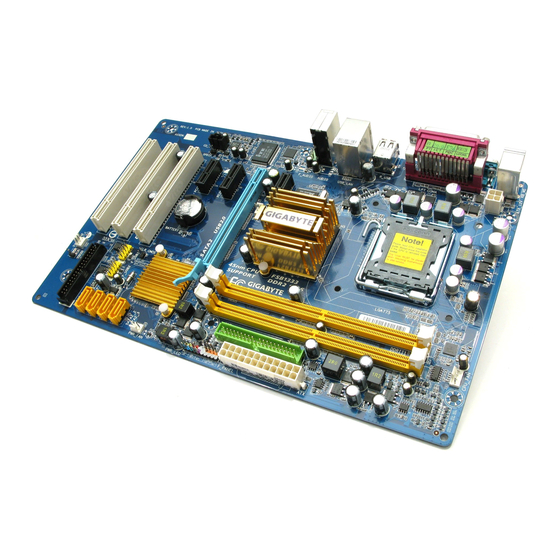
GA-P31-ES3G
LGA775 socket motherboard for Intel
Core
processor family/
®
TM
Intel
Pentium
processor family/Intel
Celeron
processor family
®
®
®
®
User’s Manual
Rev. 1101
12ME-P31ES3G-1101R
Related Manuals for Gigabyte GA-P31-ES3G
Summary of Contents for Gigabyte GA-P31-ES3G
-
Page 1
GA-P31-ES3G LGA775 socket motherboard for Intel Core processor family/ ® Intel Pentium processor family/Intel Celeron processor family ® ® ® ® User’s Manual Rev. 1101 12ME-P31ES3G-1101R… -
Page 3: Identifying Motherboard Revision
GIGABYTE’s prior written permission. Documentation Classifications In order to assist in the use of this product, GIGABYTE provides the following types of documentations: For detailed product information, carefully read the User’s Manual. For instructions on how to use GIGABYTE’s unique features, read or download the information on/from the SupportMotherboardTechnology Guide page on our website.
-
Page 4: Table Of Contents
Box Contents … 6 Optional Items … 6 GA-P31-ES3G Motherboard Layout … 7 Block Diagram … 8 Chapter 1 Hardware Installation … 9 Installation Precautions … 9 Product Specifications … 10 Installing the CPU and CPU Cooler … 13 1-3-1 Installing the CPU …
-
Page 5
Chapter 3 Drivers Installation … 53 Installing Chipset Drivers … 53 Application Software … 54 Technical Manuals … 54 Contact … 55 System … 55 Download Center … 56 Chapter 4 Unique Features … 57 Xpress Recovery2 … 57 BIOS Update Utilities … 62 4-2-1 Updating the BIOS with the Q-Flash Utility … -
Page 6: Box Contents
Box Contents GA-P31-ES3G motherboard Motherboard driver disk User’s Manual One IDE cable and one floppy disk drive cable Two SATA 3Gb/s cables I/O Shield • The box contents above are for reference only and the actual items shall depend on product package you obtain.
-
Page 7: Ga-P31-Es3G Motherboard Layout
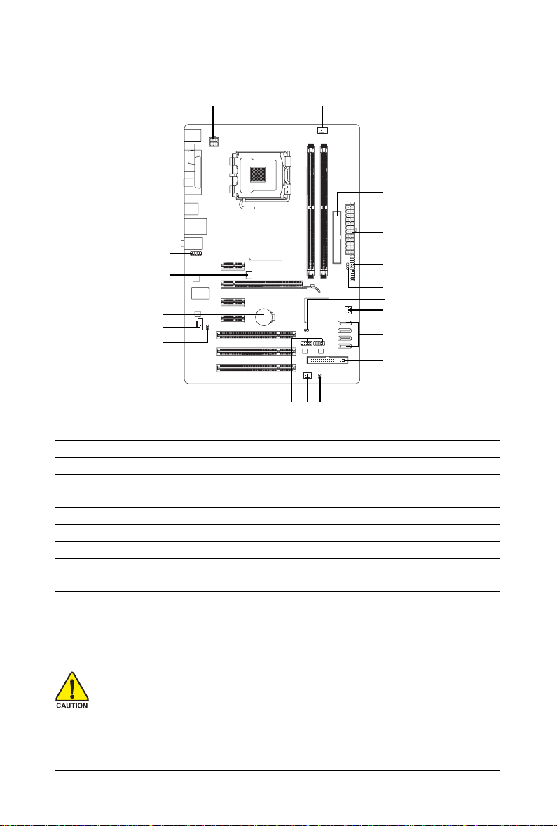
GA-P31-ES3G Motherboard Layout ATX_12V KB_MS COAXIAL AUDIO F_AUDIO PCIE_1 RTL8111C PCIE_16 IT8718 PCIE_2 CODEC PCIE_3 PCI1 PCI2 PCI3 CPU_FAN LGA775 Intel P31/ ® SYS_FAN1 Intel ® BATTERY CLR_CMOS F_USB1 F_USB2 M_BIOS SYS_FAN2 — 7 — PWR_FAN ICH7 SATA2_3 SATA2_2 SATA2_1…
-
Page 8: Block Diagram
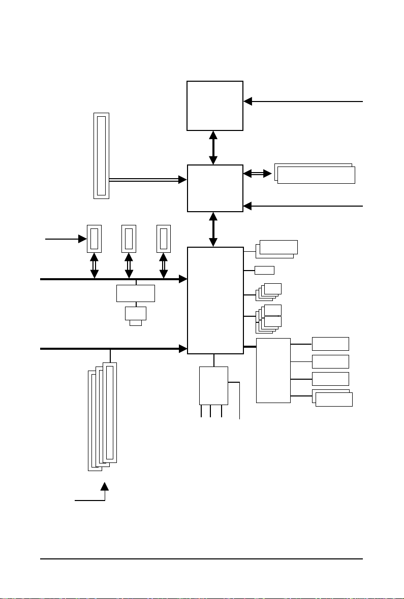
Block Diagram PCIe CLK (100 MHz) PCI Express x16 3 PCI Express x1 PCIe CLK (100 MHz) PCI Express Bus RTL8111C RJ45 PCI Bus 3 PCI PCI CLK (33 MHz) LGA775 Processor Interface Intel ® P31/G31 Intel ® ICH7 CODEC — 8 — CPU CLK+/- (333/266/200 MHz)
-
Page 9: Chapter 1 Hardware Installation
Chapter 1 Hardware Installation Installation Precautions The motherboard contains numerous delicate electronic circuits and components which can become damaged as a result of electrostatic discharge (ESD). Prior to installation, carefully read the user’s manual and follow these procedures: Prior to installation, do not remove or break motherboard S/N (Serial Number) sticker or •…
-
Page 10: Product Specifications
Product Specifications Support for an Intel Intel Intel Intel Intel (Go to GIGABYTE’s website for the latest CPU support list.) L2 cache varies with CPU Front Side Bus 1333/1066/800 MHz FSB Chipset North Bridge: Intel South Bridge: Intel Memory 2 x 1.8V DDR2 DIMM sockets supporting up to 4 GB of system memory…
-
Page 11
Internal Connectors 1 x 24-pin ATX main power connector 1 x 4-pin ATX 12V power connector 1 x floppy disk drive connector 1 x IDE connector 4 x SATA 3Gb/s connectors 1 x CPU fan header 2 x system fan headers 1 x power fan header 1 x front panel header 1 x front panel audio header… -
Page 12
(Note 4) Available functions in EasyTune may differ by motherboard model. (Note 5) Due to the hardware limitation, you must install the Intel Core 2 Duo/ Pentium Dual-Core/ Celeron Dual-Core/ Celeron 400 Series CPU to enable support for Easy Energy Saver. GA-P31-ES3G Motherboard (Note 4) (Note 5) Windows Vista/XP ®… -
Page 13: Installing The Cpu And Cpu Cooler
Read the following guidelines before you begin to install the CPU: • Make sure that the motherboard supports the CPU. (Go to GIGABYTE’s website for the latest CPU support list.) • Always turn off the computer and unplug the power cord from the power outlet before installing the CPU to prevent hardware damage.
-
Page 14
Step 5: Once the CPU is properly inserted, replace the load plate and push the CPU socket lever back into its locked position. GA-P31-ES3G Motherboard Step 2: Lift the metal load plate from the CPU socket. (DO NOT touch socket contacts.) -
Page 15: Installing The Cpu Cooler
1-3-2 Installing the CPU Cooler Follow the steps below to correctly install the CPU cooler on the motherboard. (The following procedure uses Intel boxed cooler as the example cooler.) ® Step 1: Apply an even and thin layer of thermal grease on the surface of the installed CPU.
-
Page 16: Installing The Memory
• Make sure that the motherboard supports the memory. It is recommended that memory of the same capacity, brand, speed, and chips be used. (Go to GIGABYTE’s website for the latest memory support list.) • Always turn off the computer and unplug the power cord from the power outlet before installing the memory to prevent hardware damage.
-
Page 17: Installing A Memory
1-4-2 Installing a Memory Before installing a memory module , make sure to turn off the computer and unplug the power cord from the power outlet to prevent damage to the memory module. DDR2 DIMMs are not compatible to DDR DIMMs. Be sure to install DDR2 DIMMs on this motherboard.
-
Page 18: Installing An Expansion Card
Example: Installing and Removing a PCI Express x16 Graphics Card: • Removing the Card: Gently push back on the lever on the slot and then lift the card straight out from the slot. GA-P31-ES3G Motherboard PCI Express x1 Slot PCI Express x16 Slot PCI Slot •…
-
Page 19: Back Panel Connectors
Back Panel Connectors PS/2 Keyboard and PS/2 Mouse Port Use the upper port (green) to connect a PS/2 mouse and the lower port (purple) to connect a PS/2 keyboard. Parallel Port Use the parallel port to connect devices such as a printer, scanner and etc. The parallel port is also called a printer port.
-
Page 20
To enable 7.1-channel audio, you have to use an HD front panel audio module and enable the multi-channel audio feature through the audio driver. Refer to the instructions on setting up a 2/4/5.1/7.1-channel audio configuration in Chapter 5, «Configuring 2/4/5.1/7.1-Channel Audio.» GA-P31-ES3G Motherboard — 20 -… -
Page 21: Internal Connectors
Internal Connectors ATX_12V CPU_FAN SYS_FAN1/SYS_FAN2 PWR_FAN SATA2_0/1/2/3 PWR_LED Read the following guidelines before connecting external devices: • First make sure your devices are compliant with the connectors you wish to connect. • Before installing the devices, be sure to turn off the devices and your computer. Unplug the power cord from the power outlet to prevent damage to the devices.
-
Page 22
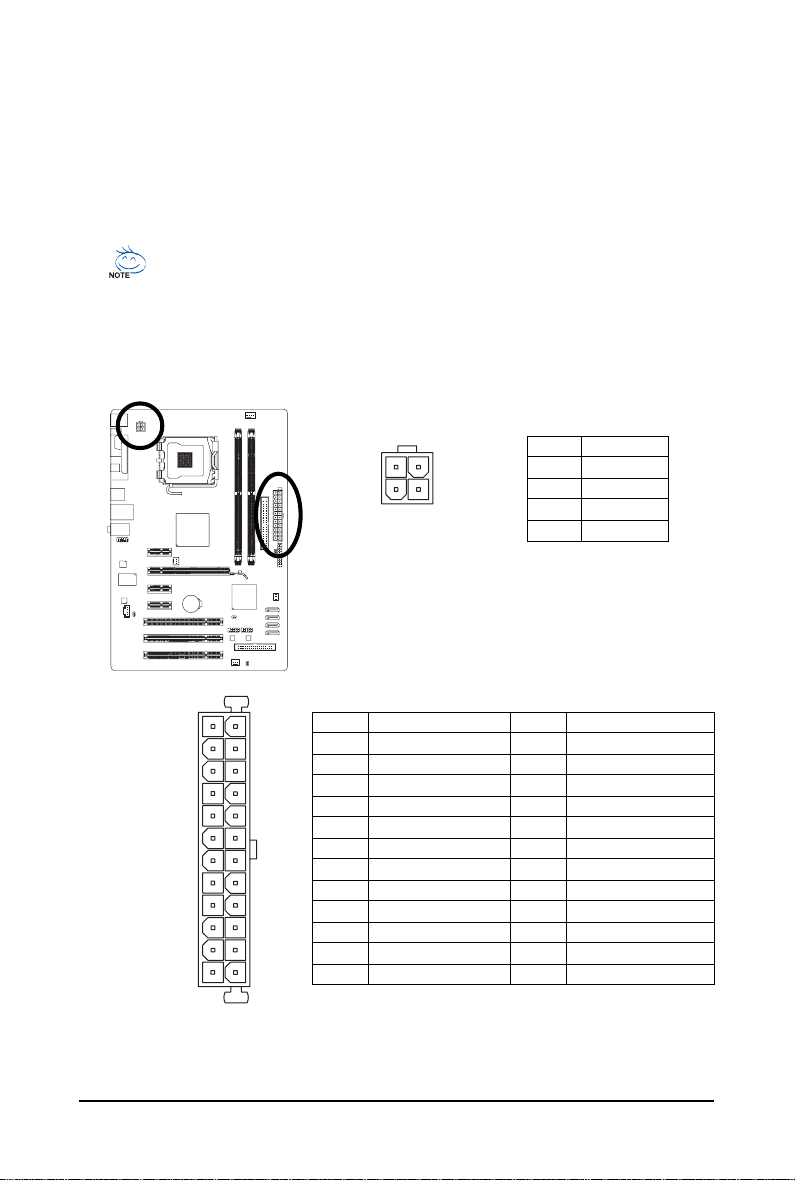
When using a 2×12 power supply, remove the protective cover from the main power connector on the motherboard. Do not insert the power supply cable into pins under the protective cover when using a 2×10 power supply. GA-P31-ES3G Motherboard ATX_12V ATX: Pin No. -
Page 23
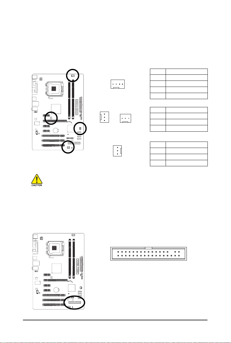
3/4/5) CPU_FAN/SYS_FAN1/SYS_FAN2/PWR_FAN (Fan Headers) The motherboard has a 4-pin CPU fan header (CPU_FAN), two 3-pin system fan headers (SYS_FAN1 and SYS_FAN2), and a 3-pin power fan header (PWR_FAN). Most fan headers possess a foolproof insertion design. When connecting a fan cable, be sure to connect it in the correct orientation (the black connector wire is the ground wire). -
Page 24
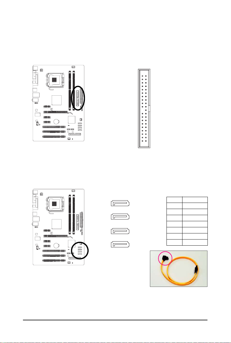
 SATA2_0/1/2/3 (SATA 3Gb/s Connectors, Controlled by ICH7) The SATA connectors conform to SATA 3Gb/s standard and are compatible with SATA 1.5Gb/s standard. Each SATA connector supports a single SATA device. GA-P31-ES3G Motherboard SATA2_3 SATA2_2 SATA2_1…
 -
Page 25: System Power Led Header
9) PWR_LED (System Power LED Header) This header can be used to connect a system power LED on the chassis to indicate system power status. The LED is on when the system is operating. The LED keeps blinking when the system is in S1 sleep state.
-
Page 26: F_Panel
LED, hard drive activity LED, speaker and etc. When connecting your chassis front panel module to this header, make sure the wire assign- ments and the pin assignments are matched correctly. GA-P31-ES3G Motherboard Speaker Connector Power Switch…
-
Page 27
12) CD_IN (CD In Connector) You may connect the audio cable that came with your optical drive to the header. 13) SPDIF_O (S/PDIF Out Header) This header supports digital S/PDIF out and connects a S/PDIF digital audio cable (provided by expansion cards) for digital audio output from your motherboard to certain expansion cards like graphics cards and sound cards. -
Page 28: Clear Cmos Jumper
• After system restart, go to BIOS Setup to load factory defaults (select Load Optimized Defaults) or manually configure the BIOS settings (refer to Chapter 2, «BIOS Setup,» for BIOS configurations). GA-P31-ES3G Motherboard Open: Normal Short: Clear CMOS Values — 28 — Pin No.
-
Page 29
16) CI (Chassis Intrusion Header) This motherboard provides a chassis detection feature that detects if the chassis cover has been removed. This function requires a chassis with chassis intrusion detection design. 17) BATTERY The battery provides power to keep the values (such as BIOS configurations, date, and time information) in the CMOS when the computer is turned off. -
Page 30
GA-P31-ES3G Motherboard — 30 -… -
Page 31: Chapter 2 Bios Setup
To see more advanced BIOS Setup menu options, you can press <Ctrl> + <F1> in the main menu of the BIOS Setup program. To upgrade the BIOS, use either the GIGABYTE Q-Flash or @BIOS utility. Q-Flash allows the user to quickly and easily upgrade or back up BIOS without entering the •…
-
Page 32: Startup Screen
BIOS Setup settings. You can access Boot Menu again to change the first boot device setting as needed. <End>: Q-Flash Press the <End> key to access the Q-Flash utility directly without having to enter BIOS Setup first. GA-P31-ES3G Motherboard — 32 — Function Keys Function Keys…
-
Page 33: The Main Menu
The Main Menu Once you enter the BIOS Setup program, the Main Menu (as shown below) appears on the screen. Use arrow keys to move among the items and press <Enter> to accept or enter a sub-menu. (Sample BIOS Version: E4) CMOS Setup Utility-Copyright (C) 1984-2008 Award Software Standard CMOS Features Advanced BIOS Features…
-
Page 34
(Pressing <F10> can also carry out this task.) Exit Without Saving Abandon all changes and the previous settings remain in effect. Pressing <Y> to the confirmation message will exit BIOS Setup. (Pressing <Esc> can also carry out this task.) GA-P31-ES3G Motherboard — 34 -… -
Page 35: Standard Cmos Features
Standard CMOS Features CMOS Setup Utility-Copyright (C) 1984-2008 Award Software Date (mm:dd:yy) Time (hh:mm:ss) IDE Channel 0 Master IDE Channel 0 Slave IDE Channel 2 Master IDE Channel 2 Slave IDE Channel 3 Master IDE Channel 3 Slave Drive A Floppy 3 Mode Support Halt On Base Memory…
-
Page 36
Base Memory Also called conventional memory. Typically, 640 KB will be reserved for the MS-DOS operating system. Extended Memory The amount of extended memory. Total Memory The total amount of memory installed on the system. GA-P31-ES3G Motherboard — 36 -… -
Page 37: Advanced Bios Features
Advanced BIOS Features CMOS Setup Utility-Copyright (C) 1984-2008 Award Software Hard Disk Boot Priority First Boot Device Second Boot Device Third Boot Device Password Check HDD S.M.A.R.T. Capability (Note) Limit CPUID Max. to 3 No-Execute Memory Protect CPU Enhanced Halt (C1E) CPU Thermal Monitor 2(TM2) CPU EIST Function (Note)
-
Page 38
With virtualization, one computer system can function as multiple virtual systems. (Default: Enabled) Full Screen LOGO Show Allows you to determine whether to display the GIGABYTE Logo at system startup. Disabled displays normal POST message. (Default: Enabled) Init Display First Specifies the first initiation of the monitor display from the installed PCI graphics card or PCI Express graphics card. -
Page 39: Integrated Peripherals
Integrated Peripherals CMOS Setup Utility-Copyright (C) 1984-2008 Award Software On-Chip Primary PCI IDE On-Chip SATA Mode x PATA IDE Set to SATA Port 0/2 Set to SATA Port 1/3 Set to USB Controller USB 2.0 Controller USB Keyboard Support USB Mouse Support Legacy USB storage detect Azalia Codec Onboard H/W LAN…
-
Page 40: Usb Controller
When No LAN Cable Is Attached… If no LAN cable is attached to the motherboard, the Status fields of all four pairs of wires will show Open and the Length fields show 0m, as shown in the figure above. GA-P31-ES3G Motherboard SMART LAN / Length…
-
Page 41
When LAN Cable Is Functioning Normally… If no cable problem is detected on the LAN cable connected to a Gigabit hub or a 10/100 Mbps hub, the following message will appear: Start detecting at Port… Link Detected —> 100Mbps Cable Length= 30m Link Detected Displays transmission speed Cable Length… -
Page 42: Power Management Setup
Power On by Ring Allows the system to be awakened from an ACPI sleep state by a wake-up signal from a modem that supports wake-up function. (Default: Enabled) (Note) Supported on Windows GA-P31-ES3G Motherboard Power Management Setup [S3(STR)] [Instant-Off] [Enabled]…
-
Page 43
Resume by Alarm Determines whether to power on the system at a desired time. (Default: Disabled) If enabled, set the date and time as following: Date (of Month) Alarm : Turn on the system at a specific time on each day or on a specific day in a month. -
Page 44: Pnp/Pci Configurations
PCI1 IRQ Assignment Auto 3,4,5,7,9,10,11,12,14,15 PCI2 IRQ Assignment Auto 3,4,5,7,9,10,11,12,14,15 PCI3 IRQ Assignment Auto 3,4,5,7,9,10,11,12,14,15 GA-P31-ES3G Motherboard PnP/PCI Configurations [Auto] [Auto] [Auto] +/-/PU/PD: Value F10: Save F6: Fail-Safe Defaults BIOS auto-assigns IRQ to the first PCI slot. (Default) Assigns IRQ 3,4,5,7,9,10,11,12,14,15 to the first PCI slot.
-
Page 45: Pc Health Status
PC Health Status CMOS Setup Utility-Copyright (C) 1984-2008 Award Software Reset Case Open Status Case Opened Vcore DDR18V +3.3V +12V Current CPU Temperature Current CPU FAN Speed Current POWER FAN Speed Current SYSTEM FAN1 Speed Current SYSTEM FAN2 Speed CPU Warning Temperature CPU FAN Fail Warning POWER FAN Fail Warning SYSTEM FAN1 Fail Warning…
-
Page 46
Enables or disables the CPU fan speed control function. Enabled allows the CPU fan to run at different speed according to the CPU temperature. You can adjust the fan speed with EasyTune based on system requirements. If disabled, CPU fan runs at full speed. (Default: Enabled) GA-P31-ES3G Motherboard — 46 -… -
Page 47: Mb Intelligent Tweaker(M.i.t.)
MB Intelligent Tweaker(M.I.T.) CMOS Setup Utility-Copyright (C) 1984-2008 Award Software Robust Graphics Booster (Note) CPU Clock Ratio (Note) Fine CPU Clock Ratio x CPU Frequency O.C. FSB1600 CPU CPU Host Clock Control x CPU Host Frequency (Mhz) PCI Express Frequency (Mhz) Performance Enhance System Memory Multiplier (SPD) Memory Frequency (Mhz) 533…
-
Page 48
******** System Voltage Optimized System Voltage Control Determines whether to manually set the system voltages. Auto lets BIOS automatically set the system voltages as required. Manual allows all voltage control items below to be configurable. (Default: Manual) GA-P31-ES3G Motherboard ******** — 48 -… -
Page 49
DDR2 OverVoltage Control Allows you to set memory voltage. Normal Supplies the memory voltage as required. (Default) +0.1V ~ +0.7V Increases memory voltage by 0.1V to 0.7V at 0.1V increment. Note: Increasing memory voltage may result in damage to the memory. PCI-E OverVoltage Control Allows you to set PCIe voltage. -
Page 50: Load Fail-Safe Defaults
Press <Enter> on this item and then press the <Y> key to load the optimal BIOS default settings. The BIOS defaults settings helps the system to operate in optimum state. Always load the Optimized defaults after updating the BIOS or after clearing the CMOS values. GA-P31-ES3G Motherboard Load Fail-Safe Defaults Load Optimized Defaults…
-
Page 51: Set Supervisor/User Password
2-12 Set Supervisor/User Password CMOS Setup Utility-Copyright (C) 1984-2008 Award Software Standard CMOS Features Advanced BIOS Features Integrated Peripherals Power Management Setup PnP/PCI Configurations PC Health Status MB Intelligent Tweaker(M.I.T.) ESC: Quit F8: Q-Flash Press <Enter> on this item and type the password with up to 8 characters and then press <Enter>. You will be requested to confirm the password.
-
Page 52: Save & Exit Setup
Press <Enter> on this item and press the <Y> key. This exits the BIOS Setup without saving the changes made in BIOS Setup to the CMOS. Press <N> or <Esc> to return to the BIOS Setup Main Menu. GA-P31-ES3G Motherboard Load Fail-Safe Defaults…
-
Page 53: Chapter 3 Drivers Installation
Chapter 3 Drivers Installation Installing Chipset Drivers • Before installing the drivers, first install the operating system. (The following instructions use Windows XP as the example operating system.) • After installing the operating system, insert the motherboard driver disk into your optical drive. The driver Autorun screen is automatically displayed which looks like that shown in the screen shot below.
-
Page 54: Application Software
Application Software This page displays all the utilities and applications that GIGABYTE develops and some free software. You can click the Install button on the right of an item to install it. Technical Manuals This page provides GIGABYTE’s application guides, content descriptions for this driver disk, and the motherboard manuals.
-
Page 55: Contact
Contact Click the URL on this page to link to the GIGABYTE Web site. Or read the last page of this manual to check the contact information for GIGABYTE Taiwan headquarter or worldwide branch offices. System This page provides the basic system information.
-
Page 56: Download Center
Download Center To update the BIOS, drivers, or applications, click the Download Center button to link to the GIGABYTE Web site. The latest version of the BIOS, drivers, or applications will be displayed. GA-P31-ES3G Motherboard — 56 -…
-
Page 57: Chapter 4 Unique Features
Chapter 4 Unique Features Xpress Recovery2 Before You Begin: • Xpress Recovery2 will check the first physical hard drive* for the operating system. Xpress Recovery2 can only back up/restore the first physical hard drive that has the operating system installed. •…
-
Page 58
Recovery2 (10 GB or more is recommended; actual size requirements vary, depending on the amount of data) (Figure 2). Figure 1 3. Select a file system (for example, NTFS) and begin the installation of the operating system (Figure 3). Figure 3 GA-P31-ES3G Motherboard Figure 2 — 58 -… -
Page 59
4. After the operating system is installed, right-click the My Computer icon on your desktop and select Manage (Figure 4). Go to Computer Management to check disk allocation. Xpress Recovery2 will save the backup file to the unallocated space (black stripe along the top)(Figure 5). Please note that if there is no enough unallocated space, Xpress Recovery2 cannot save the backup file. -
Page 60
Xpress Recovery2 will begin the backup process (Figure 11). Figure 10 3. When finished, go to Disk Management to check disk allocation. Figure 12 GA-P31-ES3G Motherboard Figure 8 Figure 9 Figure 11 Xpress Recovery2 will automatically create a new partition to store the backup image file. -
Page 61
D. Using the Restore Function in Xpress Recovery2 Select RESTORE to restore the backup to your hard drive in case the system breaks down. The RESTORE option will not be present if no backup is created before (Figure 13, 14). Figure 13 E. -
Page 62: Bios Update Utilities
4-2-1 Updating the BIOS with the Q-Flash Utility A. Before You Begin: 1. From GIGABYTE’s website, download the latest compressed BIOS update file that matches your motherboard model. 2. Extract the file and save the new BIOS file (e.g. P31ES3G.F1) to your floppy disk, USB flash drive, or hard drive.
-
Page 63
B. Updating the BIOS When updating the BIOS, choose the location where the BIOS file is saved. The follow procedure assumes that you save the BIOS file to a floppy disk. Step 1: 1. Insert the floppy disk containing the BIOS file into the floppy disk drive. In the main menu of Q-Flash, use the up or down arrow key to select Update BIOS from Drive and press <Enter>. -
Page 64
F8: Q-Flash Step 6: Select Save & Exit Setup and then press <Y> to save settings to CMOS and exit BIOS Setup. The procedure is complete after the system restarts. GA-P31-ES3G Motherboard Load Fail-Safe Defaults Load Optimized Defaults Set Supervisor Password Set User Password Save &… -
Page 65: Updating The Bios With The @Bios Utility
BIOS or a system that is unable to start. 3. Do not use the G.O.M. (GIGABYTE Online Management) function when using @BIOS. 4. GIGABYTE product warranty does not cover any BIOS damage or system failure resulting from an inadequate BIOS flashing.
-
Page 66: Easytune 5 Pro
Toggles among Easy Mode, Advanced Mode, and Graphics Mode Displays the CPU frequency Shows the supported function(s) Go to GIGABYTE website to update EasyTune 5 Pro Opens EasyTune 5 Pro help file Quits or minimizes the EasyTune 5 Pro interface Performance Enhancement…
-
Page 67: Easy Energy Saver
The Easy Energy Saver Interface A. Meter Mode In Meter Mode, GIGABYTE Easy Energy Saver shows how much power they have saved in a set period of time. Meter Mode — Button Information Table Button Description…
-
Page 68
Energy Saver is under the enable status, and power savings meter is unable to reset to zero. (Note 5) Easy Energy Saver Meter will automatically reset when the total power saving reaches 99999999 Watts. GA-P31-ES3G Motherboard (Note 4) Core 2 Extreme/ Core ®… -
Page 69: Chapter 5 Appendix
Chapter 5 Appendix Configuring Audio Input and Output 5-1-1 Configuring 2/4/5.1/7.1-Channel Audio The motherboard provides three audio jacks on the back panel which support 2/4/5.1/7.1 ture to the right shows the default audio jack assignments. The integrated HD (High Definition) audio provides jack retasking capability that allows the user to change the func- tion for each jack through the audio driver.
-
Page 70
Everytime you connect an audio device to an audio jack, the Connected device box appears. Select the device according to the type of device you connect. Then click OK to complete the configuration. GA-P31-ES3G Motherboard 7.1-Channel Speakers: — 70 — Front Speaker Out… -
Page 71
B. Configuring Sound Effect: You may configure an audio environment on the Sound Effect tab. C. Activating an AC’97 Front Panel Audio Module: If your chassis provides an AC’97 front panel audio module, to activate the AC’97 functionality, click the tool icon on the Audio I/O tab. -
Page 72: Configuring S/Pdif Out
(or disable) the output source. Click OK to complete the configuration. (Note) The actual location of the SPDIF Out connector may differ by model. GA-P31-ES3G Motherboard Connect a S/PDIF coaxial cable to an external decoder for transmitting the S/PDIF digital audio signals.
-
Page 73: Configuring Microphone Recording
5-1-3 Configuring Microphone Recording Step 1: After installing the audio driver, the Audio Manager icon will appear in your system tray. Double-click the icon to access the Audio Control Panel. Step 2: Connect your microphone to the Mic in jack (pink) on the back panel or the Line in jack on the front panel.
-
Page 74
Based on the audio specifications, to adjust the re- cording sound, use the Recording option to set the recording sound for your recording device(s) altogether. GA-P31-ES3G Motherboard Select Realtek HD Audio Input in the Mixer device list Recording Control — 74 -… -
Page 75: Using The Sound Recorder
Step 6: To raise the recording and playing sound for the microphone, go to Options in Master Volume and select Advanced Controls. Click the Advanced button under a volume control option (e.g. Front Green In, Front Pink In). In the Other Controls field, select the 1 Microphone Boost check box.
-
Page 76: Troubleshooting
1 long, 2 short: Monitor or graphics card error 1 long, 3 short: Keyboard error 1 long, 9 short: BIOS ROM error Continuous long beeps: Graphics card not inserted properly Continuous short beeps: Power error GA-P31-ES3G Motherboard — 76 -…
-
Page 77: Troubleshooting Procedure
5-2-2 Troubleshooting Procedure If you encounter any troubles during system startup, follow the troubleshooting procedure below to solve the problem. Turn off the power. Remove all peripherals, connecting cables, and power cord etc. Make sure the motherboard does not short-circuit with the chassis or other metal objects.
-
Page 78
If the procedure above is unable to solve your problem, contact the place of purchase or local dealer for help. Or go to the SupportTechnical Service Zone page to submit your question. Our customer service staff will reply you as soon as possible. GA-P31-ES3G Motherboard — 78 — The power supply, CPU or CPU socket might fail. -
Page 79: Regulatory Statements
«end of life» product. Restriction of Hazardous Substances (RoHS) Directive Statement GIGABYTE products have not intended to add and safe from hazardous substances (Cd, Pb, Hg, Cr+6, PBDE and PBB). The parts and components have been carefully selected to meet RoHS requirement.
-
Page 80
«end of life» products, and generally improve our quality of life by ensuring that potentially hazardous substances are not released into the environment and are disposed of properly. China Restriction of Hazardous Substances Table The following table is supplied in compliance with China’s Restriction of Hazardous Substances (China RoHS) requirements: GA-P31-ES3G Motherboard — 80 -… -
Page 81
— 81 — Appendix… -
Page 82
GA-P31-ES3G Motherboard — 82 -… -
Page 83
FAX: +86-28-85256822 Xian TEL: +86-29-85531943 FAX: +86-29-85510930 Shenyang TEL: +86-24-83992901 FAX: +86-24-83992909 GIGABYTE TECHNOLOGY (INDIA) LIMITED — India WEB address : http://www.gigabyte.in Saudi Arabia WEB address : http://www.gigabyte.com.sa GIGABYTE TECHNOLOGY PTY. LTD. — Australia WEB address : http://www.gigabyte.com.au — 83 -… -
Page 84
WEB address : http://www.gigabyte.co.yu Kazakhstan WEB address : http://www.giga-byte.kz You may go to the GIGABYTE website, select your language in the language list on the top right corner of the website. To submit a technical or non-technical (Sales/ Marketing) question, please link to : http://ggts.gigabyte.com.tw…
-
Драйверы
13
-
Инструкции по эксплуатации
7
Языки:

Gigabyte GA-P31-ES3G инструкция по эксплуатации
(72 страницы)
- Языки:Венгерский, Греческий, Испанский, Итальянский, Немецкий, Польский, Португальский, Русский, Турецкий, Французский, Чешский
-
Тип:
PDF -
Размер:
18.6 MB -
Описание:
Installation Guidebook


На NoDevice можно скачать инструкцию по эксплуатации для Gigabyte GA-P31-ES3G. Руководство пользователя необходимо для ознакомления с правилами установки и эксплуатации Gigabyte GA-P31-ES3G. Инструкции по использованию помогут правильно настроить Gigabyte GA-P31-ES3G, исправить ошибки и выявить неполадки.
Посмотреть инструкция для Gigabyte GA-P31-ES3G бесплатно. Руководство относится к категории материнские платы, 1 человек(а) дали ему среднюю оценку 7.5. Руководство доступно на следующих языках: английский. У вас есть вопрос о Gigabyte GA-P31-ES3G или вам нужна помощь? Задайте свой вопрос здесь
Не можете найти ответ на свой вопрос в руководстве? Вы можете найти ответ на свой вопрос ниже, в разделе часто задаваемых вопросов о Gigabyte GA-P31-ES3G.
Какая ширина Gigabyte GA-P31-ES3G?
Какая толщина Gigabyte GA-P31-ES3G?
Инструкция Gigabyte GA-P31-ES3G доступно в русский?
Не нашли свой вопрос? Задайте свой вопрос здесь
Ga-p31-es3g, User’s manual
- Text mode
- Original mode
Advertising

GA-P31-ES3G
LGA775 socket motherboard for Intel
®
Core
TM
processor family/
Intel
®
Pentium
®
processor family/Intel
®
Celeron
®
processor family
User’s Manual
Rev. 1101
12ME-P31ES3G-1101R
Advertising
Table of contents
Document Outline
- i.pdf
- q.pdf
- b.pdf
- cd.pdf
- f.pdf
- a.pdf

GA-P31-ES3G
LGA775 socket motherboard for Intel
®
Core
TM
processor family/
Intel
®
Pentium
®
processor family/Intel
®
Celeron
®
processor family
User’s Manual
Rev. 1101
12ME-P31ES3G-1101R

Jul. 24, 2008
Motherboard
GA-P31-ES3G
Motherboard
GA-P31-ES3G
Jul. 24, 2008
Copyright
© 2008 GIGA-BYTE TECHNOLOGY CO., LTD. All rights reserved.
The trademarks mentioned in this manual are legally registered to their respective owners.
Disclaimer
Information in this manual is protected by copyright laws and is the property of GIGABYTE.
Changes to the specifications and features in this manual may be made by GIGABYTE without prior
notice. No part of this manual may be reproduced, copied, translated, transmitted, or published in any
form or by any means without GIGABYTE’s prior written permission.
Documentation Classifications
In order to assist in the use of this product, GIGABYTE provides the following types of documentations:
For detailed product information, carefully read the User’s Manual.
For instructions on how to use GIGABYTE’s unique features, read or download the
information on/from the SupportMotherboardTechnology Guide page on our website.
For product-related information, check on our website at:
http://www.gigabyte.com.tw
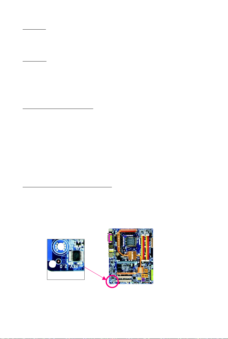
Identifying Your Motherboard Revision
The revision number on your motherboard looks like this: «REV: X.X.» For example, «REV: 1.0»
means the revision of the motherboard is 1.0. Check your motherboard revision before updating
motherboard BIOS, drivers, or when looking for technical information.
Example:

— 4 —
Table of Contents
Box Contents ………………………………………………………………………………………………….. 6
Optional Items………………………………………………………………………………………………….. 6
GA-P31-ES3G Motherboard Layout …………………………………………………………………… 7
Block Diagram…………………………………………………………………………………………………. 8
Chapter 1 Hardware Installation ………………………………………………………………………… 9
1-1 Installation Precautions ………………………………………………………………………….9
1-2 Product Specifications ………………………………………………………………………… 10
1-3 Installing the CPU and CPU Cooler …………………………………………………….. 13
1-3-1 Installing the CPU …………………………………………………………………………………… 13
1-3-2 Installing the CPU Cooler ………………………………………………………………………..15
1- 4 Installing the Memory …………………………………………………………………………. 16
1-4-1 Dual Channel Memory Configuration ………………………………………………………. 16
1-4-2 Installing a Memory………………………………………………………………………………… 17
1- 5 Installing an Expansion Card ………………………………………………………………. 18
1- 6 Back Panel Connectors ……………………………………………………………………… 19
1- 7 Internal Connectors ……………………………………………………………………………. 21
Chapter 2 BIOS Setup……………………………………………………………………………………. 31
2-1 Startup Screen….……………………………………………………………………………….. 32
2- 2 The Main Menu …………………………………………………………………………………. 33
2- 3 Standard CMOS Features ………………………………………………………………….. 35
2-4 Advanced BIOS Features…………………………………………………………………… 37
2-5 Integrated Peripherals ………………………………………………………………………….39
2- 6 Power Management Setup ………………………………………………………………….. 42
2- 7 PnP/PCI Configurations……………………………………………………………………… 44
2- 8 PC Health Status ……………………………………………………………………………….45
2- 9 MB Intelligent T weaker(M.I.T.) …………………………………………………………….. 47
2-10 Load Fail-Safe Defaults……………………………………………………………………….. 50
2- 1 1 Load Optimized Defaults ……………………………………………………………………… 50
2-12 Set Supervisor/User Password…………………………………………………………… 51
2-13 Save & Exit Setup…………………………………………………………………………….. 52
2-14 Exit Without Saving …………………………………………………………………………… 52

— 5 —
Chapter 3 Drivers Installation ………………………………………………………………………….. 53
3- 1 Installing Chipset Drivers ……………………………………………………………………. 53
3- 2 Application Software ……………………………………………………………………………54
3- 3 Technical Manuals……………………………………………………………………………… 54
3-4 Contact…………………………………………………………………………………………….. 55
3-5 System…………………………………………………………………………………………….. 55
3- 6 Download Center……………………………………………………………………………….. 56
Chapter 4 Unique Features…………………………………………………………………………….. 57
4- 1 Xpress Recovery2 …………………………………………………………………………….. 5 7
4-2 BIOS Update Utilities…………………………………………………………………………. 62
4-2-1 Updating the BIOS with the Q-Flash Utility ……………………………………………… 62
4-2-2 Updating the BIOS with the @BIOS Utility ………………………………………………. 65
4- 3 EasyTune 5 Pro ………………………………………………………………………………… 66
4-4 Easy Energy Saver ………………………………………………………………………….. 67
Chapter 5 Appendix ………………………………………………………………………………………. 69
5-1 Configuring Audio Input and Output……………………………………………………….. 69
5-1-1 Configuring 2/4/5.1/7.1-Channel Audio …………………………………………………… 69
5-1-2 Configuring S/PDIF Out …………………………………………………………………………… 72
5-1-3 Configuring Microphone Recording …………………………………………………………. 73
5-1-4 Using the Sound Recorder ……………………………………………………………………… 75
5-2 Troubleshooting ………………………………………………………………………………….. 76
5-2-1 Frequently Asked Questions ………………………………………………………………….. 76
5-2-2 Troubleshooting Procedure …………………………………………………………………….. 77
5-3 Regulatory Statements ……………………………………………………………………….. 79
— 6 —
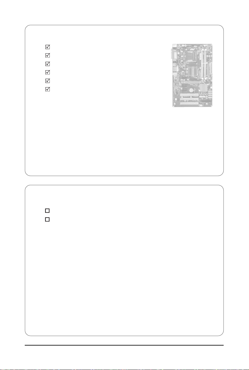
Box Contents
GA-P31-ES3G motherboard
Motherboard driver disk
User’s Manual
One IDE cable and one floppy disk drive cable
Two SATA 3Gb/s cables
I/O Shield
Optional Items
2-port USB 2.0 bracket (Part No. 12CR1-1UB030-51R)
2-port SATA power cable (Part No. 12CF1-2SERPW-01R)
• The box contents above are for reference only and the actual items shall depend on product package you obtain.
The box contents are subject to change without notice.
• The motherboard image is for reference only.
— 7 —
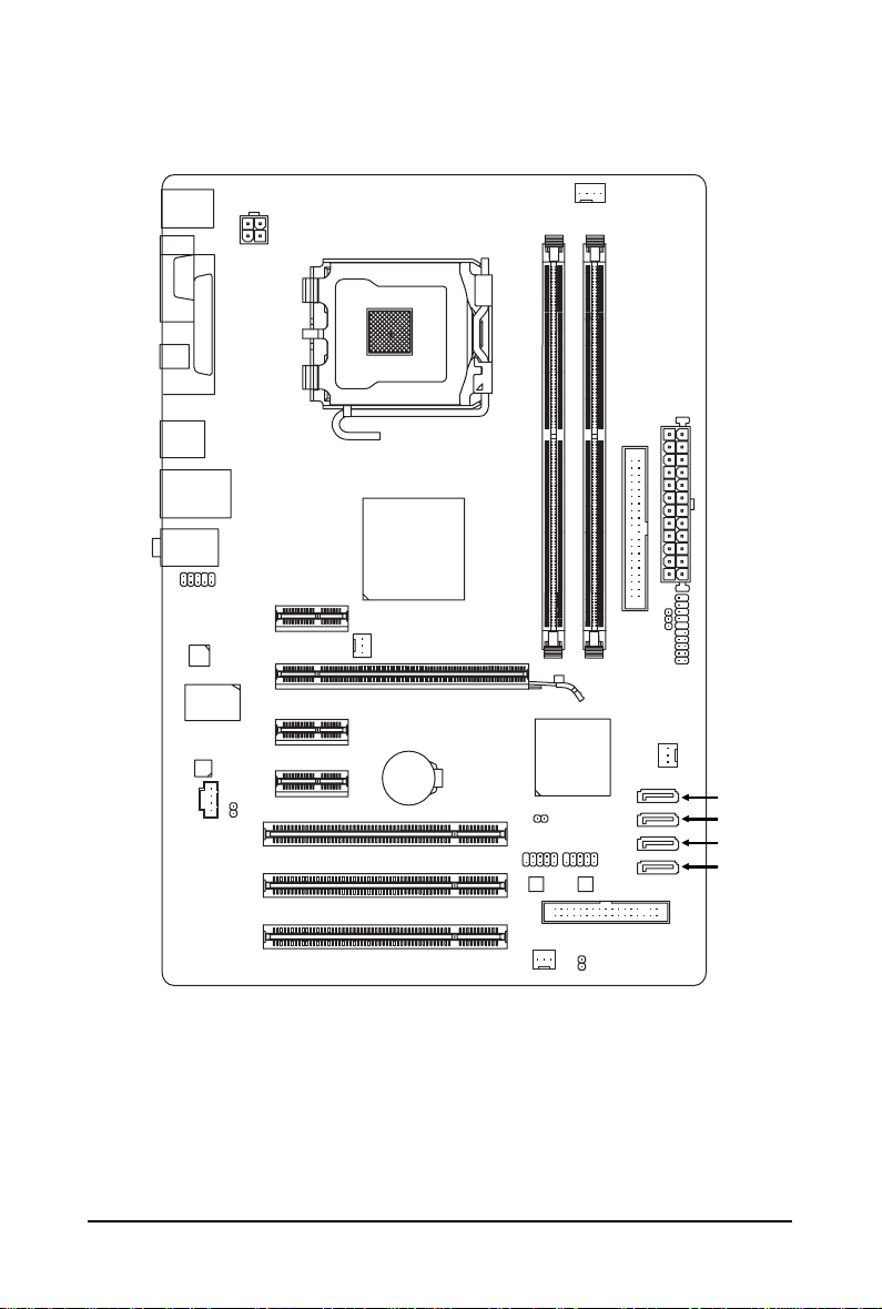
GA-P31-ES3G Motherboard Layout
KB_MS
CPU_FAN
LGA775
ATX
GA-P31-ES3G
USB
LAN
CD_IN
F_AUDIO
AUDIO
M_BIOS
PCIE_16
PCIE_1
F_USB2
IDE
PCIE_2
CI
DDRII1
DDRII2
BATTERY
F_PANEL
IT8718
SATA2_1
ATX_12V
Intel
®
P31/
G31
Intel
®
ICH7
PWR_LED
FDD
PCIE_3
SATA2_0
PCI1
PCI2
PCI3
R_USB
CLR_CMOS
LPT
CODEC
RTL8111C
F_USB1
SATA2_3
SATA2_2
SYS_FAN2
COMA
SPDIF_O
COAXIAL
PWR_FAN
SYS_FAN1
B_BIOS
— 8 —
Block Diagram
LGA775
Processor
Host
Interface
Intel
®
P31/G31
MCH CLK
(333/266/200 MHz)
Intel
®
ICH7
3 PCI
PCI Bus
PCI Express Bus
Dual Channel Memory
4 SATA 3Gb/s
PCI CLK
(33 MHz)
PCIe CLK
(100 MHz)
PCI Express x16
8 USB Ports
IT8718
Floppy
PS/2 KB/Mouse
LPT Port
CPU CLK+/-
(333/266/200 MHz)
3 PCI Express x1
PCIe CLK
(100 MHz)
x1
ATA-100/66/33 IDE Channel
COM Port
DDR2 1066/800/667 MHz
RJ45
LAN
RTL8111C
x1 x1
Line-Out (Front Speaker Out)
MIC (Center/Subwoofer Speaker Out)
CODEC
Line-In (Rear Speaker Out)
SPDIF Out
Dual BIOS

Hardware Installation— 9 —
1-1 Installation Precautions
The motherboard contains numerous delicate electronic circuits and components which can become
damaged as a result of electrostatic discharge (ESD). Prior to installation, carefully read the user’s
manual and follow these procedures:
• Prior to installation, do not remove or break motherboard S/N (Serial Number) sticker or
warranty sticker provided by your dealer. These stickers are required for warranty validation.
• Always remove the AC power by unplugging the power cord from the power outlet before
installing or removing the motherboard or other hardware components.
• When connecting hardware components to the internal connectors on the motherboard,
make sure they are connected tightly and securely.
• When handling the motherboard, avoid touching any metal leads or connectors.
• It is best to wear an electrostatic discharge (ESD) wrist strap when handling electronic
components such as a motherboard, CPU or memory. If you do not have an ESD wrist strap,
keep your hands dry and first touch a metal object to eliminate static electricity.
• Prior to installing the motherboard, please have it on top of an antistatic pad or within an
electrostatic shielding container.
• Before unplugging the power supply cable from the motherboard, make sure the power supply
has been turned off.
• Before turning on the power, make sure the power supply voltage has been set according to
the local voltage standard.
• Before using the product, please verify that all cables and power connectors of your hardware
components are connected.
• T o prevent damage to the motherboard, do not allow screws to come in contact with the
motherboard circuit or its components.
• Make sure there are no leftover screws or metal components placed on the motherboard or
within the computer casing.
• Do not place the computer system on an uneven surface
.
• Do not place the computer system in a high-temperature environment.
• Turning on the computer power during the installation process can lead to damage to system
components as well as physical harm to the user.
• If you are uncertain about any installation steps or have a problem related to the use of the
product, please consult a certified computer technician.
Chapter 1 Hardware Installation

GA-P31-ES3G Motherboard — 10 —
1-2 Product Specifications
CPU Support for an Intel
®
Core
TM
2 Extreme processor/
Intel
®
Core
TM
2 Quad processor/Intel
®
Core
TM
2 Duo processor/
Intel
®
Pentium
®
processor Extreme Edition/Intel
®
Pentium
®
D processor/
Intel
®
Pentium
®
4 processor Extreme Edition/Intel
®
Pentium
®
4 processor/
Intel
®
Celeron
®
processor in the LGA 775 package
(Go to GIGABYTE’s website for the latest CPU support list.)
L2 cache varies with CPU
Front Side Bus 1333/1066/800 MHz FSB
Chipset North Bridge: Intel
®
P31/G31 Express Chipset
South Bridge: Intel
®
ICH7
Memory 2 x 1.8V DDR2 DIMM sockets supporting up to 4 GB of system memory
(Note 1)
Dual channel memory architecture
Support for DDR2 1066/800/667 MHz memory modules
(Go to GIGABYTE’s website for the latest memory support list.)
Audio Realtek ALC888 codec
High Definition Audio
2/4/5.1/7.1-channel
(Note 2)
Support for S/PDIF Out
Support for CD In
LAN RTL 8111C chip (10/100/1000 Mbit)
Expansion Slots 1 x PCI Express x16 slot
3 x PCI Express x1 slots
3 x PCI slots
Storage Interface South Bridge:
— 1 x IDE connector supporting ATA-100/66/33 and up to 2 IDE devices
— 4 x SATA 3Gb/s connectors supporting up to 4 SATA 3Gb/s devices
iTE IT8718 chip:
— 1 x floppy disk drive connector supporting up to 1 floppy disk drive
USB Integrated in the South Bridge
Up to 8 USB 2.0/1.1 ports (4 on the back panel, 4 via the USB brackets
connected to the internal USB headers)

Hardware Installation— 11 —
Internal Connectors 1 x 24-pin ATX main power connector
1 x 4-pin ATX 12V power connector
1 x floppy disk drive connector
1 x IDE connector
4 x SATA 3Gb/s connectors
1 x CPU fan header
2 x system fan headers
1 x power fan header
1 x front panel header
1 x front panel audio header
1 x CD In connector
1 x S/PDIF Out header
2 x USB 2.0/1.1 headers
1 x chassis intrusion header
1 x power LED header
Back Panel 1 x PS/2 keyboard port
Connectors 1 x PS/2 mouse port
1 x parallel port
1 x serial port
1 x coaxial S/PDIF Out connector
4 x USB 2.0/1.1 ports
1 x RJ-45 port
3 x audio jacks (Line In/Line Out/Microphone)
I/O Controller iTE IT8718 chip
Hardware Monitor System voltage detection
CPU temperature detection
CPU/System/Power fan speed detection
CPU overheating warning
CPU/System/Power fan fail warning
CPU fan speed control
(Note 3)
BIOS 2 x 4 Mbit flash
Use of licensed AWARD BIOS
Support for DualBIOS
TM
PnP 1.0a, DMI 2.0, SM BIOS 2.4, ACPI 1.0b

GA-P31-ES3G Motherboard — 12 —
Unique Features Support for @BIOS
Support for Download Center
Support for Q-Flash
Support for EasyTune
(Note 4)
Support for Xpress Install
Support for Xpress Recovery2
Support for Virtual Dual BIOS
Support for Easy Energy Saver
(Note 5)
Bundled Software Norton Internet Security (OEM version)
Operating System Support for Microsoft
®
Windows
®
Vista/XP
Form Factor ATX Form Factor; 30.5cm x 19.4cm
(Note 1) Based on standard PC architecture, a certain amount of memory is reserved for system
usage and therefore the actual memory size is less than the stated amount. For example,
4 GB of memory size will instead be shown as 3.xx GB during system startup.
(Note 2) To enable 7.1-channel audio, you have to use an HD front panel audio module and enable the
multi-channel audio feature through the audio driver.
(Note 3) Whether the CPU fan speed control function is supported will depend on the CPU cooler you
install.
(Note 4) Available functions in EasyTune may differ by motherboard model.
(Note 5) Due to the hardware limitation, you must install the Intel
®
Core
TM
2 Extreme/ Core
TM
2 Quad/
Core
TM
2 Duo/ Pentium Dual-Core/ Celeron Dual-Core/ Celeron 400 Series CPU to enable
support for Easy Energy Saver.
Hardware Installation— 13 —
1-3 Installing the CPU and CPU Cooler
Read the following guidelines before you begin to install the CPU:
• Make sure that the motherboard supports the CPU.
(Go to GIGABYTE’s website for the latest CPU support list.)
• Always turn off the computer and unplug the power cord from the power outlet before
installing the CPU to prevent hardware damage.
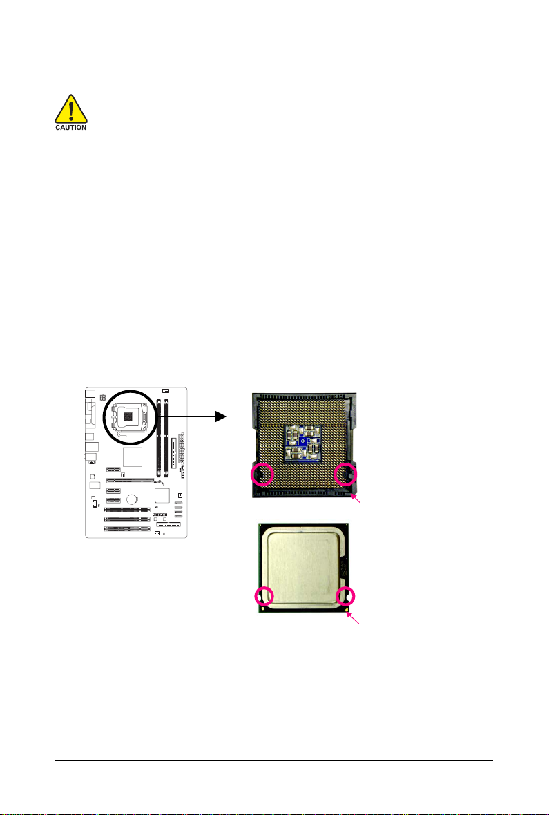
• Locate the pin one of the CPU. The CPU cannot be inserted if oriented incorrectly. (Or you
may locate the notches on both sides of the CPU and alignment keys on the CPU socket.)
• Apply an even and thin layer of thermal grease on the surface of the CPU.
• Do not turn on the computer if the CPU cooler is not installed, otherwise overheating and
damage of the CPU may occur.
• Set the CPU host frequency in accordance with the CPU specifications. It is not recom-
mended that the system bus frequency be set beyond hardware specifications since it
does not meet the standard requirements for the peripherals. If you wish to set the frequency
beyond the standard specifications, please do so according to your hardware specifications
including the CPU, graphics card, memory, hard drive, etc.
1-3-1 Installing the CPU
A. Locate the alignment keys on the motherboard CPU socket and the notches on the CPU.
NotchNotch
Alignment Key
Alignment Key
LGA 775 CPU
LGA775 CPU Socket
Pin One Corner of the CPU Socket
Triangle Pin One Marking on the CPU
GA-P31-ES3G Motherboard — 14 —
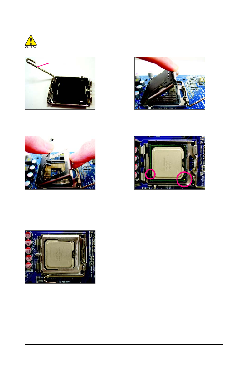
B. Follow the steps below to correctly install the CPU into the motherboard CPU socket.
Before installing the CPU, make sure to turn off the computer and unplug the power
cord from the power outlet to prevent damage to the CPU.
Step 1:
Completely raise the CPU socket lever.
CPU Socket Lever
Step 3:
Remove the protective socket cover from the
load plate. (To protect the CPU socket, always
replace the protective socket cover when the
CPU is not installed.)
Step 5:
Once the CPU is properly inserted, replace
the load plate and push the CPU socket lever
back into its locked position.
Step 2:
Lift the metal load plate from the CPU socket.
(DO NOT touch socket contacts.)
Step 4:
Hold the CPU with your thumb and index
fingers. Align the CPU pin one marking (triangle)
with the pin one corner of the CPU socket (or
you may align the CPU notches with the socket
alignment keys) and gently insert the CPU
into position.
Hardware Installation— 15 —
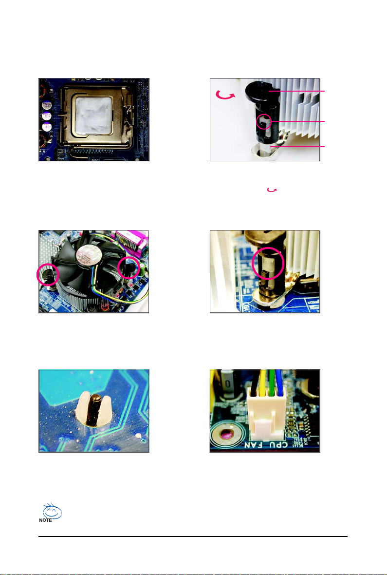
1-3-2 Installing the CPU Cooler
Follow the steps below to correctly install the CPU cooler on the motherboard. (The following procedure
uses Intel
®
boxed cooler as the example cooler.)
Step 1:
Apply an even and thin layer of thermal grease
on the surface of the installed CPU.
Male
Push Pin
Female
Push Pin
The Top
of Female
Push Pin
Direction of
the Arrow Sign
on the Male
Push Pin
Step 2:
Before installing the cooler, note the direction
of the arrow sign on the male push pin.
(Turning the push pin along the direction of
arrow is to remove the cooler, on the contrary,
is to install.)
Step 3:
Place the cooler atop the CPU, aligning the
four push pins through the pin holes on the
motherboard. Push down on the push pins
diagonally.
Step 4:
You should hear a «click» when pushing down each
push pin. Check that the Male and Female push pins
are joined closely. (Refer to your CPU cooler instal-
lation manual for instructions on installing the cooler.)
Use extreme care when removing the CPU cooler because the thermal grease/tape between
the CPU cooler and CPU may adhere to the CPU. Inadequately removing the CPU cooler may
damage the CPU.
Step 5:
After the installation, check the back of the
motherboard. If the push pin is inserted as the
picture above, the installation is complete.
Step 6:
Finally, attach the power connector of the CPU
cooler to the CPU fan header (CPU_FAN) on
the motherboard.
GA-P31-ES3G Motherboard — 16 —
1-4 Installing the Memory
Read the following guidelines before you begin to install the memory:
• Make sure that the motherboard supports the memory. It is recommended that memory of
the same capacity, brand, speed, and chips be used.
(Go to GIGABYTE’s website for the latest memory support list.)
• Always turn off the computer and unplug the power cord from the power outlet before
installing the memory to prevent hardware damage.
• Memory modules have a foolproof design. A memory module can be installed in only one
direction. If you are unable to insert the memory, switch the direction.
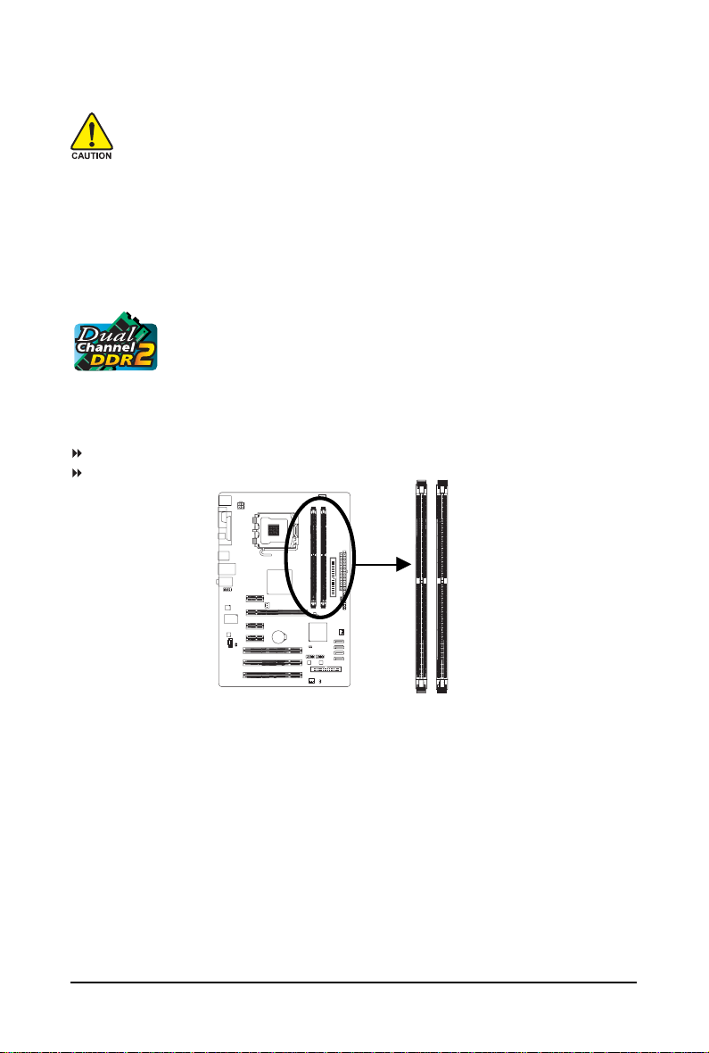
1-4-1 Dual Channel Memory Configuration
This motherboard provides two DDR2 memory sockets and supports Dual Channel
Technology. After the memory is installed, the BIOS will automatically detect the
specifications and capacity of the memory. Enabling Dual Channel memory mode
will double the original memory bandwidth.
The two DDR2 memory sockets are divided into two channels and each channel has one memory
socket as following:
Channel 0: DDRII1
Channel 1: DDRII2
Due to chipset limitation, read the following guidelines before installing the memory in Dual Channel mode.
1. Dual Channel mode cannot be enabled if only one DDR2 memory module is installed.
2. When enabling Dual Channel mode with two memory modules, it is recommended that
memory of the same capacity, brand, speed, and chips be used.
DDRII1
DDRII2
Hardware Installation— 17 —
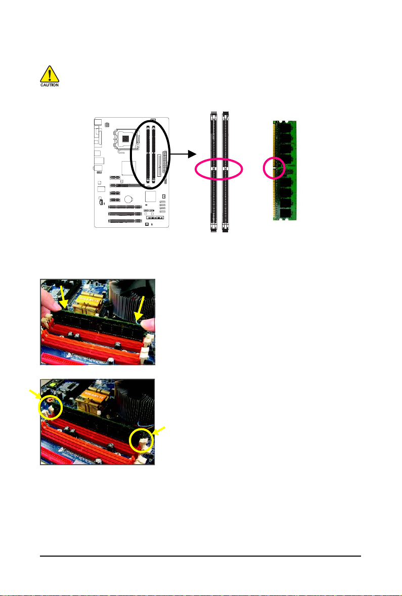
1-4-2 Installing a Memory
Notch
DDR2 DIMM
Before installing a memory module , make sure to turn off the computer and unplug
the power cord from the power outlet to prevent damage to the memory module.
DDR2 DIMMs are not compatible to DDR DIMMs. Be sure to install DDR2 DIMMs on
this motherboard.
A DDR2 memory module has a notch, so it can only fit in one direction. Follow the steps below to
correctly install your memory modules in the memory sockets.
Step 1:
Note the orientation of the memory module. Spread the retaining
clips at both ends of the memory socket. Place the memory
module on the socket. As indicated in the picture on the left,
place your fingers on the top edge of the memory, push down
on the memory and insert it vertically into the memory socket.
Step 2:
The clips at both ends of the socket will snap into place when
the memory module is securely inserted.
GA-P31-ES3G Motherboard — 18 —
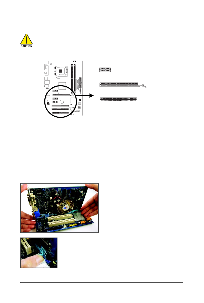
1-5 Installing an Expansion Card
Read the following guidelines before you begin to install an expansion card:
• Make sure the motherboard supports the expansion card. Carefully read the manual that
came with your expansion card.
• Always turn off the computer and unplug the power cord from the power outlet before
installing an expansion card to prevent hardware damage.
Follow the steps below to correctly install your expansion card in the expansion slot.
1. Locate an expansion slot that supports your card. Remove the metal slot cover from the chassis back panel.
2. Align the card with the slot, and press down on the card until it is fully seated in the slot.
3. Make sure the metal contacts on the card are completely inserted into the slot.
4. Secure the card’s metal bracket to the chassis back panel with a screw.
5. After installing all expansion cards, replace the chassis cover(s).
6. Turn on your computer. If necessary, go to BIOS Setup to make any required BIOS changes for
your expansion card(s).
7. Install the driver provided with the expansion card in your operating system.
• Installing a Graphics Card:
Gently push down on the top edge of the card
until it is fully inserted into the PCI Express x16
slot. Make sure the card is securely seated in
the slot and does not rock.
• Removing the Card:
Gently push back on the lever on the slot and then lift the card straight out
from the slot.
Example: Installing and Removing a PCI Express x16 Graphics Card:
PCI Express x1 Slot
PCI Express x16 Slot
PCI Slot
Hardware Installation— 19 —
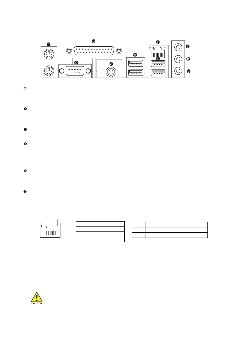
1-6 Back Panel Connectors
PS/2 Keyboard and PS/2 Mouse Port
Use the upper port (green) to connect a PS/2 mouse and the lower port (purple) to connect a PS/2
keyboard.
Parallel Port
Use the parallel port to connect devices such as a printer, scanner and etc. The parallel port is also
called a printer port.
Serial Port
Use the serial port to connect devices such as a mouse, modem or other peripherals.
Coaxial S/PDIF Out Connector
This connector provides digital audio out to an external audio system that supports digital coaxial
audio. Before using this feature, ensure that your audio system provides a coaxial digital audio in
connector.
USB Port
The USB port supports the USB 2.0/1.1 specification. Use this port for USB devices such as an
USB keyboard/mouse, USB printer, USB flash drive and etc.
RJ-45 LAN Port
The Gigabit Ethernet LAN port provides Internet connection at up to 1 Gbps data rate. The following
describes the states of the LAN port LEDs.
• When removing the cable connected to a back panel connector, first remove the cable
from your device and then remove it from the motherboard.
• When removing the cable, pull it straight out from the connector. Do not rock it side to side
to prevent an electrical short inside the cable connector.
Activity LED:
State Description
Blinking Data transmission or receiving is occurring
Off No data transmission or receiving is occurring
Connection/Speed LED:
State Description
Orange 1 Gbps data rate
Green 100 Mbps data rate
Off 10 Mbps data rate
Activity LED
Connection/
Speed LED
LAN Port

GA-P31-ES3G Motherboard — 20 —
Line In Jack (Blue)
The default line in jack. Use this audio jack for line in devices such as an optical drive, walkman, etc.
Line Out Jack (Green)
The default line out jack. Use this audio jack for a headphone or 2-channel speaker. This jack can
be used to connect front speakers in a 4/5.1-channel audio configuration.
Mic In Jack (Pink)
The default Mic in jack. Microphones must be connected to this jack.
To enable 7.1-channel audio, you have to use an HD front panel audio module and enable
the multi-channel audio feature through the audio driver. Refer to the instructions on setting
up a 2/4/5.1/7.1-channel audio configuration in Chapter 5, «Configuring 2/4/5.1/7.1-Channel
Audio.»
Hardware Installation— 21 —
1-7 Internal Connectors
Read the following guidelines before connecting external devices:
• First make sure your devices are compliant with the connectors you wish to connect.
• Before installing the devices, be sure to turn off the devices and your computer. Unplug the
power cord from the power outlet to prevent damage to the devices.
• After installing the device and before turning on the computer, make sure the device cable
has been securely attached to the connector on the motherboard.
1
2
3
10
8
6
16
13
12
4
15
17
1) ATX_12V
2) AT X
3) CPU_FAN
4) SYS_FAN1/SYS_FAN2
5) PWR_FAN
6) FDD
7) IDE
 SATA2_0/1/2/3
9) PWR_LED
10) F_AUDIO
11) F_PANEL
12) CD_IN
13) SPDIF_O
14) F_USB1/F_USB2
15) CLR_CMOS
16) CI
17) BATTERY
14
7
11
9
4
5
GA-P31-ES3G Motherboard — 22 —
ATX_12V:
Pin No. Definition
1GND
2GND
3 +12V
4 +12V
ATX_12V
1
3
2
4
131
24
12
ATX
ATX:
Pin No. Definition
13 3.3V
14 -12V
15 GND
16 PS_ON(soft On/Off)
17 GND
18 GND
19 GND
20 -5V
21 +5V
22 +5V
23 +5V (Only for 2×12-pin ATX)
24 GND (Only for 2×12-pin ATX)
Pin No. Definition
1 3.3V
2 3.3V
3 GND
4 +5V
5 GND
6 +5V
7 GND
8 Power Good
9 5V SB(stand by +5V)
10 +12V
11 +12V (Only for 2×12-pin A TX)
12 3.3V (Only for 2×12-pin ATX)
1/2) ATX_12V/ATX (2×2 12V Power Connector and 2×12 Main Power Connector)
With the use of the power connector, the power supply can supply enough stable power to all the
components on the motherboard. Before connecting the power connector, first make sure the
power supply is turned off and all devices are properly installed. The power connector possesses
a foolproof design. Connect the power supply cable to the power connector in the correct orientation.
The 12V power connector mainly supplies power to the CPU. If the 12V power connector is not
connected, the computer will not start.
• To meet expansion requirements, it is recommended that a power supply that can withstand
high power consumption be used (500W or greater). If a power supply is used that does not
provide the required power, the result can lead to an unstable or unbootable system.
• The main power connector is compatible with power supplies with 2×10 power
connectors. When using a 2×12 power supply, remove the protective cover from the
main power connector on the motherboard. Do not insert the power supply cable into pins
under the protective cover when using a 2×10 power supply.
Hardware Installation— 23 —
3/4/5) CPU_FAN/SYS_F AN1/SYS_F AN2/PWR_FAN (Fan Headers)
The motherboard has a 4-pin CPU fan header (CPU_FAN), two 3-pin system fan headers (SYS_FAN1
and SYS_FAN2), and a 3-pin power fan header (PWR_FAN). Most fan headers possess a foolproof
insertion design. When connecting a fan cable, be sure to connect it in the correct orientation (the black
connector wire is the ground wire). The motherboard supports CPU fan speed control, which requires
the use of a CPU fan with fan speed control design. For optimum heat dissipation, it is recommended
that a system fan be installed inside the chassis.
Pin No. Definition
1 GND
2 +12V / Speed Control
3 Sense
4 Speed Control
CPU_FAN:
Pin No. Definition
1 GND
2 +12V
3 Sense
SYS_FAN1/SYS_FAN2:
CPU_FAN
1
6) FDD (Floppy Disk Drive Connector)
This connector is used to connect a floppy disk drive. The types of floppy disk drives supported
are: 360 KB, 720 KB, 1.2 MB, 1.44 MB, and 2.88 MB. Before connecting a floppy disk drive, be
sure to locate pin 1 of the connector and the floppy disk drive cable. The pin 1 of the cable is
typically designated by a stripe of different color.
1
2
33
34
• Be sure to connect fan cables to the fan headers to prevent your CPU and system from
overheating. Overheating may result in damage to the CPU or the system may hang.
• These fan headers are not configuration jumper blocks. Do not place a jumper cap on the
headers.
Pin No. Definition
1 GND
2 +12V
3 Sense
PWR_FAN
SYS_FAN1
1
1
SYS_FAN2
1
PWR_FAN
GA-P31-ES3G Motherboard — 24 —
7) IDE (IDE Connector)
The IDE connector supports up to two IDE devices such as hard drives and optical drives. Before
attaching the IDE cable, locate the foolproof groove on the connector. If you wish to connect two IDE
devices, remember to set the jumpers and the cabling according to the role of the IDE devices (for
example, master or slave). (For information about configuring master/slave settings for the IDE
devices, read the instructions from the device manufacturers.)
SATA2_0/1/2/3 (SATA 3Gb/s Connectors, Controlled by ICH7)
The SATA connectors conform to SATA 3Gb/s standard and are compatible with SATA 1.5Gb/s
standard. Each SATA connector supports a single SATA device.
39
1
40
2
Pin No. Definition
1 GND
2TXP
3 TXN
4 GND
5 RXN
6 RXP
7 GND
Please connect the L-shaped end
of the SATA 3Gb/s cable to your
SATA hard drive.
7
1
SATA2_2
7
1
SATA2_3
7
1
SATA2_0
7
1
SATA2_1
Hardware Installation— 25 —
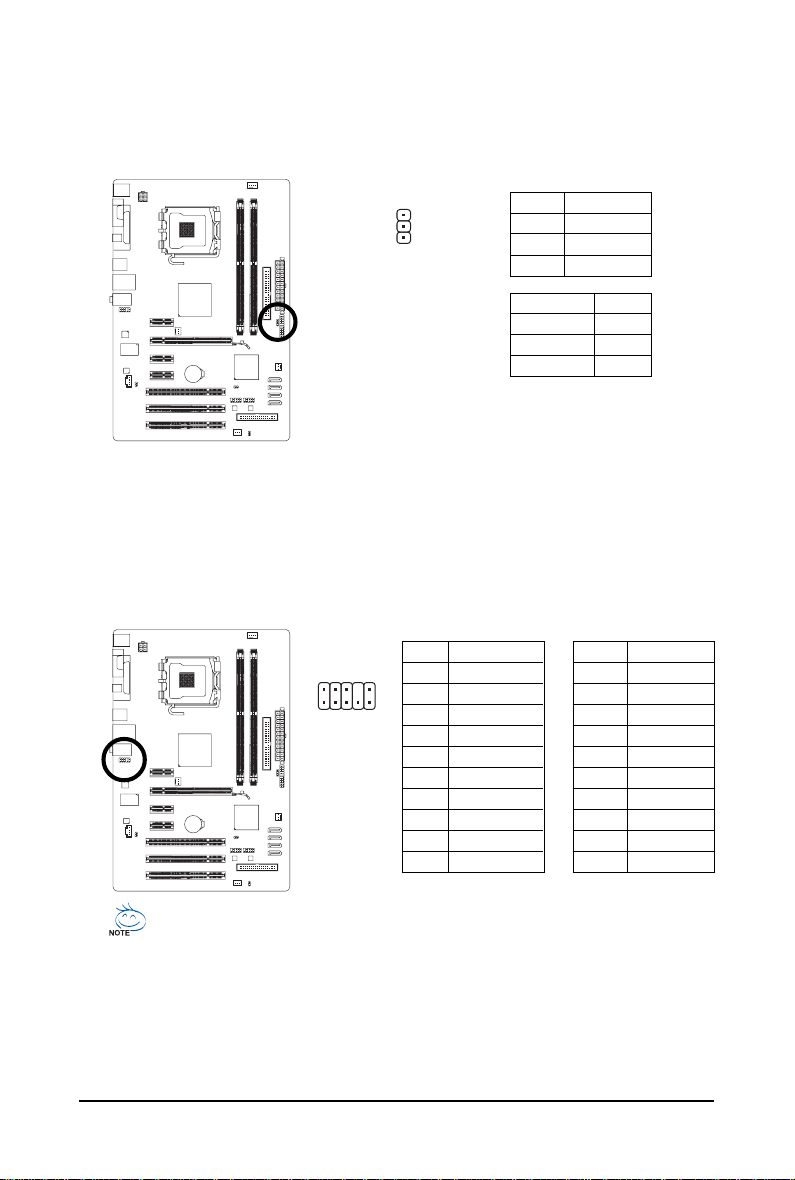
9) PWR_LED (System Power LED Header)
This header can be used to connect a system power LED on the chassis to indicate system power
status. The LED is on when the system is operating. The LED keeps blinking when the system is
in S1 sleep state. The LED is off when the system is in S3/S4 sleep state or powered off (S5).
Pin No. Definition
1 MPD+
2 MPD-
3 MPD-
1
System Status LED
S0 On
S1 Blinking
S3/S4/S5 Off
10) F_AUDIO (Front Panel Audio Header)
The front panel audio header supports Intel High Definition audio (HD) and AC’97 audio. You may
connect your chassis front panel audio module to this header. Make sure the wire assignments of
the module connector match the pin assignments of the motherboard header. Incorrect connection
between the module connector and the motherboard header will make the device unable to work
or even damage it.
Pin No. Definition
1 MIC
2 GND
3 MIC Power
4NC
5 Line Out (R)
6NC
7NC
8 No Pin
9 Line Out (L)
10 NC
For AC’97 Front Panel Audio:For HD Front Panel Audio:
Pin No. Definition
1 MIC2_L
2 GND
3 MIC2_R
4 -ACZ_DET
5 LINE2_R
6 GND
7 FAUDIO_JD
8 No Pin
9 LINE2_L
10 GND
1
2
9
10
• The front panel audio header supports HD audio by default. If your chassis provides an
AC’97 front panel audio module, refer to the instructions on how to activate AC’97 functioninality
via the audio software in Chapter 5, «Configuring 2/4/5.1/7.1-Channel Audio.»
• Audio signals will be present on both of the front and back panel audio connections
simultaneously. If you want to mute the back panel audio (only supported when using an HD
front panel audio module), refer to Chapter 5, «Configuring 2/4/5.1/7.1-Channel Audio.»
• Some chassis provide a front panel audio module that has separated connectors on each
wire instead of a single plug. For information about connecting the front panel audio
module that has different wire assignments, please contact the chassis manufacturer.
GA-P31-ES3G Motherboard — 26 —
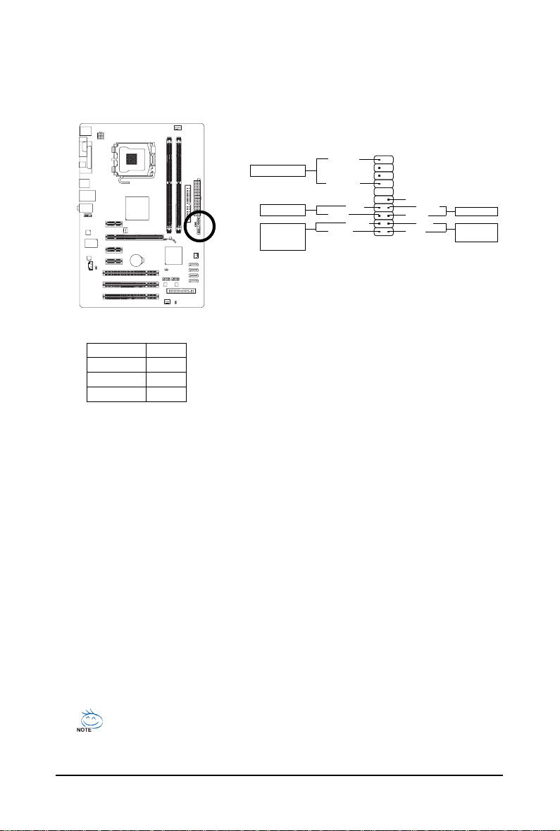
11) F_PANEL (Front Panel Header)
Connect the power switch, reset switch, speaker and system status indicator on the chassis front
panel to this header according to the pin assignments below. Note the positive and negative pins
before connecting the cables.
• PW (Power Switch, Red):
Connects to the power switch on the chassis front panel. You may configure the way to turn off
your system using the power switch (refer to Chapter 2, «BIOS Setup,» «Power Management
Setup,» for more information).
• SPEAK (Speaker, Orange):
Connects to the speaker on the chassis front panel. The system reports system startup status
by issuing a beep code. One single short beep will be heard if no problem is detected at system
startup. If a problem is detected, the BIOS may issue beeps in different patterns to indicate the
problem. Refer to Chapter 5, «Troubleshooting,» for information about beep codes.
• HD (IDE Hard Drive Activity LED, Blue)
Connects to the hard drive activity LED on the chassis front panel. The LED is on when the hard
drive is reading or writing data.
• RES (Reset Switch, Green):
Connects to the reset switch on the chassis front panel. Press the reset switch to restart the
computer if the computer freezes and fails to perform a normal restart.
• NC (Purple):
No connection
System Status LE D
S0 On
S1 Blinking
S3/S4/S5 Off
• MSG (Message/Power/Sleep LED, Yellow):
Connects to the power status indicator o n the chassis front panel. The
LED is on when the system is operating. The LED keeps blinking when
the system is in S1 sleep state. The LED is off when the system is in
S3/S4 sleep state or powered off (S5).
The front panel design may differ by chassis. A front panel module mainly consists of
power switch, reset switch, power LED, hard drive activity LED, speaker and etc. When
connecting your chassis front panel module to this header, make sure the wire assign-
ments and the pin assignments are matched correctly.
12
19
20
HD-
HD+
RES+
RES-
NC
SPEAK-
MSG-
MSG+
PW-
PW+
SPEAK+
Message LED/
Power/
Sleep LED
Power Switch
Speaker Connector
IDE Hard Drive
Activity LED
Reset Switch
 Loading…