- Manuals
- Brands
- Gigabyte Manuals
- Motherboard
- H510M H
- User manual
-
Contents
-
Table of Contents
-
Bookmarks
Quick Links
H510M H
User’s Manual
Rev. 1301
For more product details, please visit GIGABYTE’s website.
To reduce the impacts on global warming, the packaging materials of this product
are recyclable and reusable. GIGABYTE works with you to protect the environment.
Related Manuals for Gigabyte H510M H
Summary of Contents for Gigabyte H510M H
-
Page 1
H510M H User’s Manual Rev. 1301 For more product details, please visit GIGABYTE’s website. To reduce the impacts on global warming, the packaging materials of this product are recyclable and reusable. GIGABYTE works with you to protect the environment. -
Page 2
The trademarks mentioned in this manual are legally registered to their respective owners. Disclaimer Information in this manual is protected by copyright laws and is the property of GIGABYTE. Changes to the specifications and features in this manual may be made by GIGABYTE without prior notice. -
Page 3: Table Of Contents
Table of Contents H510M H Motherboard Layout ………………4 Chapter 1 Hardware Installation ………………5 Installation Precautions ………………5 Product Specifications ………………6 Installing the CPU ……………….. 9 Installing the Memory ………………9 Installing an Expansion Card …………….. 10 Back Panel Connectors ……………… 10 Internal Connectors ………………
-
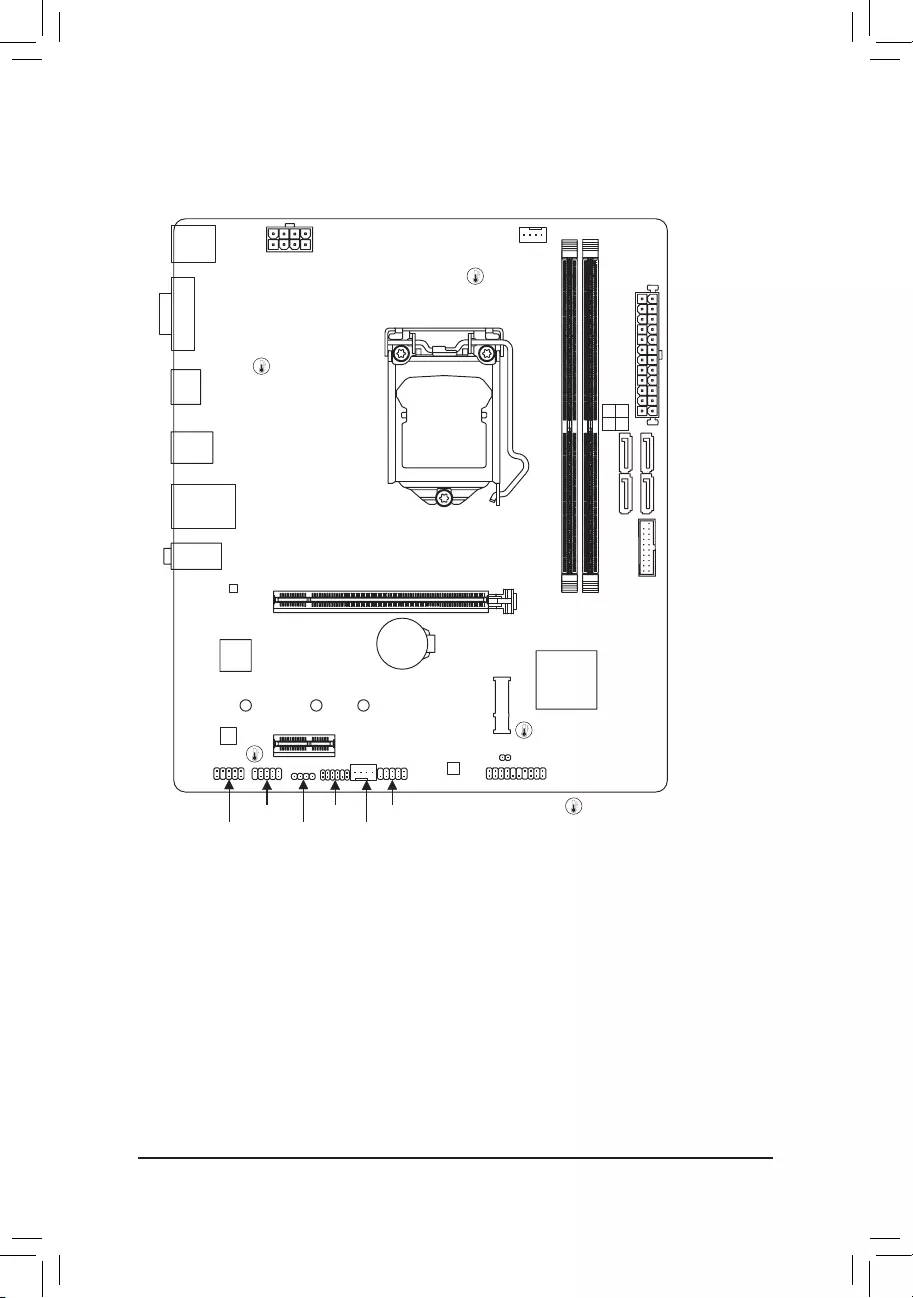
Page 4: H510M H Motherboard Layout
H510M H Motherboard Layout KB_MS_ CPU_FAN USB20 ATX_12V_2X4 LGA1200 USB_LAN AUDIO H510M H Realtek ® GbE LAN PCIEX16 ® Super I/O Intel H510 ® PCIEX1_1 CODEC M_BIOS CLR_CMOS F_PANEL Temperature sensor SPI_TPM F_USB1 F_AUDIO LED_C SYS_FAN Box Contents 5 H510M H motherboard…
-
Page 5: Chapter 1 Hardware Installation
Chapter 1 Hardware Installation Installation Precautions The motherboard contains numerous delicate electronic circuits and components which can become damaged as a result of electrostatic discharge (ESD). Prior to installation, carefully read the user’s manual and follow these procedures: • Prior to installation, make sure the chassis is suitable for the motherboard. •…
-
Page 6: 1-2 Product Specifications
Support for non-ECC Un-buffered DIMM 1Rx8/2Rx8/1Rx16 memory modules Š Support for Extreme Memory Profile (XMP) memory modules Š (Go to GIGABYTE’s website for the latest supported memory speeds and memory modules.) Onboard Integrated Graphics Processor-Intel HD Graphics support: ®…
-
Page 7
Storage Interface Š Chipset: 1 x M.2 connector (Socket 3, M key, type 2260/2280/22110 SATA and PCIe 3.0 x4/x2 SSD support) 4 x SATA 6Gb/s connectors * Refer to «1-7 Internal Connectors,» for the installation notices for the M.2 and SATA connectors. -
Page 8
System Form Factor Micro ATX Form Factor; 24.4cm x 21.0cm Š * GIGABYTE reserves the right to make any changes to the product specifications and product-related information without prior notice. Please visit the SupportUtility List Please visit GIGABYTE’s website for support lists of CPU, memory page on GIGABYTE’s website to modules, SSDs, and M.2 devices. -
Page 9: Installing The Cpu
• Make sure that the motherboard supports the memory. It is recommended that memory of the same capacity, brand, speed, and chips be used. (Go to GIGABYTE’s website for the latest supported memory speeds and memory modules.) • Always turn off the computer and unplug the power cord from the power outlet before installing the memory to prevent hardware damage.
-
Page 10: Installing An Expansion Card
The two memory sockets are divided into two channels and each channel has one memory socket as following: Channel A: DDR4_1 Channel B: DDR4_2 Due to CPU limitations, read the following guidelines before installing the memory in Dual Channel mode. Dual Channel mode cannot be enabled if only one memory module is installed.
-
Page 11
• To configure 7.1-channel audio, you need to open the audio software and select Device advanced settings > Playback Device to change the default setting first. Please visit GIGABYTE’s website for details on configuring the audio software. — 11 -… -
Page 12: Internal Connectors
Internal Connectors ATX_12V_2X4 F_AUDIO F_U32 CPU_FAN F_USB1 SYS_FAN SPI_TPM LED_C SATA3 0/1/2/3 CLR_CMOS M2A_SB F_PANEL Read the following guidelines before connecting external devices: • First make sure your devices are compliant with the connectors you wish to connect. • Before installing the devices, be sure to turn off the devices and your computer. Unplug the power cord from the power outlet to prevent damage to the devices.
-
Page 13
1/2) ATX_12V_2X4/ATX (2×4 12V Power Connector and 2×12 Main Power Connector) With the use of the power connector, the power supply can supply enough stable power to all the components on the motherboard. Before connecting the power connector, first make sure the power supply is turned off and all devices are properly installed. -
Page 14
Incorrect connection may lead to the damage of the LED strip. For how to turn on/off the lights of the LED strip please visit the «Unique Features» webpage of GIGABYTE’s website. Before installing the devices, be sure to turn off the devices and your computer. Unplug the power cord from the power outlet to prevent damage to the devices. -
Page 15
6) SATA3 0/1/2/3 (SATA 6Gb/s Connectors) USB3 F The SATA connectors conform to SATA 6Gb/s standard and are compatible with SATA 3Gb/s and SATA 1.5Gb/s standard. Each SATA connector supports a single SATA device. Pin No. Definition SATA3 To enable hot-plugging for the SATA ports, refer to Chapter 2, «BIOS Setup,» «SettingsIO Ports SATA And RST Configuration,»… -
Page 16
 F_PANEL (Front Panel Header) Connect the power switch, reset switch, speaker, chassis intrusion switch/sensor and system status indicator on the chassis to this header according to the pin assignments below. Note the positive and negative pins before connecting the cables. •…
 -
Page 17
F_USB30 F_ U 10) F_U32 (USB 3.2 Gen 1 Header) The header conforms to USB 3.2 Gen 1 and USB 2.0 specification and can provide two USB ports. For purchasing the optional 3.5″ front panel that provides two USB 3.2 Gen 1 ports, please contact the local dealer. -
Page 18
13) COM (Serial Port Header) The COM header can provide one serial port via an optional COM port cable. For purchasing the optional COM port cable, please contact the local dealer. Pin No. Definition Pin No. Definition NDCD- NDSR- NSIN NRTS- NSOUT NCTS-… -
Page 19: Chapter 2 Bios Setup
To access the BIOS Setup program, press the <Delete> key during the POST when the power is turned on. To upgrade the BIOS, use either the GIGABYTE Q-Flash or @BIOS utility. Q-Flash allows the user to quickly and easily upgrade or back up BIOS without entering the operating system.
-
Page 20: The Main Menu
The Main Menu System Time Setup Menus Configuration Items Hardware Information Option Description Current Settings Quick Access Bar allows you to quickly move to the General Help, Easy Mode, Smart Fan 6, or Q-Flash screen. Advanced Mode Function Keys <f><g> Move the selection bar to select a setup menu <h><i>…
-
Page 21: Smart Fan 6
Smart Fan 6 Use the <F6> function key to quickly switch to this screen. This screen allows you to configure fan speed related settings for each fan header or monitor your system/CPU temperature. & TUNE ALL Allows you to apply the current settings to all fan headers. &…
-
Page 22
& FAN Mode Allows you to set the operating mode for the fan. Adjusts the fan speed linearly based on the temperature. (Default) Slope Adjusts the fan speed stepwise based on the temperature. Stair & FAN Fail Warning Allows the system to emit warning sound if the fan is not connected or fails. Check the fan condition or fan connection when this occurs. -
Page 23: Favorites (F11)
Favorites (F11) Set your frequently used options as your favorites and use the <F11> key to quickly switch to the page where all of your favorite options are located. To add or remove a favorite option, go to its original page and press <Insert>…
-
Page 24: Tweaker
Tweaker Whether the system will work stably with the overclock/overvoltage settings you made is dependent on your overall system configurations. Incorrectly doing overclock/overvoltage may result in damage to CPU, chipset, or memory and reduce the useful life of these components. This page is for advanced users only and we recommend you not to alter the default settings to prevent system instability or other unexpected results.
-
Page 25
& No. of CPU Cores Enabled Allows you to select the number of CPU cores to enable in an Intel multi-core CPU (the number of CPU ® cores may vary by CPU). Auto lets the BIOS automatically configure this setting. (Default: Auto) &… -
Page 26
d C-States Control & CPU Enhanced Halt (C1E) Enables or disables Intel CPU Enhanced Halt (C1E) function, a CPU power-saving function in system halt state. ® When enabled, the CPU core frequency and voltage will be reduced during system halt state to decrease power consumption. -
Page 27
d Turbo Per Core Limit Control (Note 1) Allows you to control each CPU core limit separately. (Default: Auto) & Extreme Memory Profile (X.M.P.) (Note 2) Allows the BIOS to read the SPD data on XMP memory module(s) to enhance memory performance when enabled. -
Page 28
& Memory Enhancement Settings Provides several memory performance enhancement settings: Auto, Relax OC, Enhanced Stability, Normal, Enhanced Performance, High Frequency, High Density, and DDR-4500+. (Default: Auto) & Memory Channel Detection Message Allows you to determine whether to show an alert message when the memory is not installed in the optimal memory channel. -
Page 29: Settings
Settings ƒ Platform Power & Platform Power Management Enables or disables the Active State Power Management function (ASPM). (Default: Disabled) & PEG ASPM Allows you to configure the ASPM mode for the device connected to the CPU PEG bus. This item is configurable only when Platform Power Management is set to Enabled.
-
Page 30
& ErP Determines whether to let the system consume least power in S5 (shutdown) state. (Default: Disabled) Note: When this item is set to Enabled, the following functions will become unavailable: Resume by Alarm, power on by mouse, and power on by keyboard. &… -
Page 31
& OnBoard LAN Controller Enables or disables the onboard LAN function. (Default: Enabled) If you wish to install a 3rd party add-in network card instead of using the onboard LAN, set this item to Disabled. & Audio Controller Enables or disables the onboard audio function. (Default: Enabled) If you wish to install a 3rd party add-in audio card instead of using the onboard audio, set this item to Disabled. -
Page 32
& PXE boot wait time Allows you to configure how long to wait before you can press <Esc> to abort the PXE boot. This item is configurable only when Network Stack is enabled. (Default: 0) & Media detect count Allows you to set the number of times to check the presence of media. This item is configurable only when Network Stack is enabled. -
Page 33
& PCH PCIe Link Speed Allows you to set the operation mode of the Chipset-controlled PCI Express slots to Gen 1, Gen 2, or Gen 3. Actual operation mode is subject to the hardware specification of each slot. Auto lets the BIOS automatically configure this setting. -
Page 34: System Info
System Info. This section provides information on your motherboard model and BIOS version. You can also select the default language used by the BIOS and manually set the system time. & Access Level Displays the current access level depending on the type of password protection used. (If no password is set, the default will display as Administrator.) The Administrator level allows you to make changes to all BIOS settings;…
-
Page 35: Boot
System (Default) & Full Screen LOGO Show Allows you to determine whether to display the GIGABYTE Logo at system startup. Disabled skips the GIGABYTE Logo when the system starts up. (Default: Enabled) & Boot Option Priorities Specifies the overall boot order from the available devices. Removable storage devices that support GPT format will be prefixed with «UEFI:»…
-
Page 36
& VGA Support Allows you to select which type of operating system to boot. Enables legacy option ROM only. Auto EFI Driver Enables EFI option ROM. (Default) This item is configurable only when Fast Boot is set to Enabled or Ultra Fast. &… -
Page 37
& Other PCI devices Allows you to select whether to enable the UEFI or Legacy option ROM for the PCI device controller other than the LAN, storage device, and graphics controllers. Do not launch Disables option ROM. Enables UEFI option ROM only. (Default) UEFI Enables legacy option ROM only. -
Page 38: Save & Exit
Save & Exit & Save & Exit Setup Press <Enter> on this item and select Yes. This saves the changes to the CMOS and exits the BIOS Setup program. Select No or press <Esc> to return to the BIOS Setup Main Menu. &…
-
Page 39: Chapter 3 Appendix
You can click the Xpress Install button and «Xpress Install» will install all of the selected drivers. Or click the arrow icon to individually install the drivers you need. Please visit GIGABYTE’s website for Please visit GIGABYTE’s website for more software information.
-
Page 40: Regulatory Notices
European Commission Delegated Directive (EU) 2015/863 Statement diretivas é verificada utilizando as normas europeias harmonizadas. GIGABYTE products have not intended to add and safe from hazardous substances (Cd, Pb, Hg, Cr+6, PBDE, PBB, DEHP, BBP, DBP and DIBP). CE Declaración de conformidad…
-
Page 41: Contact Us
Contact Us GIGA-BYTE TECHNOLOGY CO., LTD. Address: No.6, Baoqiang Rd., Xindian Dist., New Taipei City 231, Taiwan TEL: +886-2-8912-4000, FAX: +886-2-8912-4005 Tech. and Non-Tech. Support (Sales/Marketing) : https://esupport.gigabyte.com WEB address (English): https://www.gigabyte.com WEB address (Chinese): https://www.gigabyte.com/tw GIGABYTE eSupport • To submit a technical or non-technical (Sales/Marketing) question, please link to: https://esupport.gigabyte.com…
H510M H Сверхпрочная материнская плата
B560M H V2 H510M H
Руководство пользователя
Преподобный 1701
Для получения более подробной информации о продукте посетите веб-сайт GIGABYTE. webсайт. https://www.gigabyte.com/Motherboard/B560M-H-V2-rev-10?m=ma#kf https://www.gigabyte.com/Motherboard/H510M-H-rev-17?m=ma #kf GIGABYTE сократит использование бумаги, чтобы выполнить свои обязательства перед гражданином мира. Кроме того, чтобы уменьшить воздействие на глобальное потепление, упаковочные материалы этого продукта подлежат вторичной переработке и повторному использованию. GIGABYTE работает с вами для защиты окружающей среды.
Авторские права © 2022 GIGA-BYTE TECHNOLOGY CO., LTD. Все права защищены. Торговые марки, упомянутые в этом руководстве, зарегистрированы на своих законных владельцев.
Заявление об ограничении ответственности Информация в этом руководстве защищена законами об авторских правах и является собственностью GIGABYTE. Компания GIGABYTE может вносить изменения в характеристики и функции в этом руководстве без предварительного уведомления. Никакая часть этого руководства не может быть воспроизведена, скопирована, переведена, передана или опубликована в любой форме и любыми средствами без предварительного письменного разрешения GIGABYTE.
Для получения подробной информации о продукте внимательно прочитайте Руководство пользователя. Для быстрой настройки продукта обратитесь к Руководству по быстрой установке на веб-сайте GIGABYTE.
webсайт.
https://download.gigabyte.com/FileList/Manual/mb_manual_installation-guide_103.pdf?m=sw
Информацию о продукте можно найти на нашем webсайт по адресу: https://www.gigabyte.com
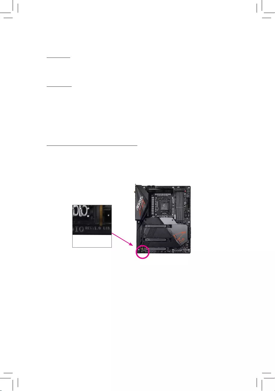
Идентификация версии вашей материнской платы Номер версии вашей материнской платы выглядит следующим образом: «REV: XX».ample, «REV: 1.0» означает версию материнской платы 1.0. Проверьте версию материнской платы перед обновлением BIOS материнской платы, драйверов или при поиске технической информации.
Exampль:
Содержание
Глава 1 Введение продукта ……………………………………………………………………………… 4 1-1 Макет материнской платы ……………………………… ……………………………………………….. 4 1-2 Содержимое упаковки……………………………………………………………… …………………………. 5
Глава 2 Установка оборудования ………………………………………………………………………….6 2-1 Меры предосторожности при установке……………………………… …………………………………………… 6 2-2 Технические характеристики продукта……………………………………………………………………… … .. 7 2-3 Установка CPU и CPU Cooler ………………………………………………………… 10 2-4 Установка памяти ………………………… ……………………………………………………. 11 2-5 Установка платы расширения ………………………………………………………………. 12 2-6 Разъемы задней панели………………………………………………………………………. 13 2-7 Внутренние разъемы……………………………………………………………………………. 15
Глава 3 Настройка BIOS …………………………………………………………………………………..24 Глава 4 Установка операционной системы и драйверов……… ……………………………………26
4-1 Установка операционной системы ……………………………………………………………… 26 4-2 Установка драйверов……………………………………… ………………………………………… 27 Нормативные уведомления………………………………………………………………………………… ……. 28 Свяжитесь с нами …………………………………………………………………………………………………. 29
— 3 —
Глава 1 Знакомство с продуктом
1-1 Компоновка материнской платы
VGA
КБ_МС_ USB20
ATX_12V_2X4
CPU_FAN ATX
LGA1200
HDMI
31
20
U32
SATA3
USB_LAN
АУДИО
ЛВС Realtek® GbE
PCIEX16
iTE® Супер ввод/вывод
B560M H V2 H510M H
НИМ
110
80
60
Кодек
PCIEX1_1
М_БИОС
COM
SPI_TPM F_USB1
F_AUDIO
LED_C
SYS_FAN
M2A_SB
DDR4_1 DDR4_2
F_U32
Intel® B560
CLR_CMOS F_PANEL Датчик температуры
— 4 —
1-2 Содержимое коробки
5 Материнская плата B560M H V2 или H510M H 5 Руководство пользователя 5 Два кабеля SATA 5 Экран ввода-вывода
* Содержимое коробки выше приведено только для справки, а фактическое количество предметов зависит от полученной вами упаковки продукта. Содержимое коробки может быть изменено без предварительного уведомления. – 5 –
Глава 2 Установка оборудования
2-1 Меры предосторожности при установке
Материнская плата содержит множество чувствительных электронных схем и компонентов, которые могут быть повреждены в результате электростатического разряда (ЭСР). Перед установкой внимательно прочитайте руководство пользователя и выполните следующие действия:
· Перед установкой убедитесь, что корпус подходит для материнской платы. · Перед установкой не удаляйте и не ломайте наклейку S/N (серийный номер) материнской платы или
гарантийную наклейку, предоставленную вашим дилером. Эти наклейки необходимы для подтверждения гарантии. · Всегда отключайте питание переменного тока, выдергивая шнур питания из розетки перед
установка или удаление материнской платы или других аппаратных компонентов. · При подключении аппаратных компонентов к внутренним разъемам на материнской плате
Убедитесь, что они соединены плотно и надежно. · При обращении с материнской платой не прикасайтесь к металлическим выводам или разъемам. · Лучше всего носить антистатический браслет (ESD) при работе с электронными
компонентов, таких как материнская плата, ЦП или память. Если у вас нет антистатического браслета, держите руки сухими и сначала прикоснитесь к металлическому предмету, чтобы снять статическое электричество. · Перед установкой материнской платы положите ее на антистатическую прокладку или в контейнер с защитой от электростатического заряда. · Перед подключением или отключением кабеля питания от материнской платы убедитесь, что питание отключено. · Перед включением питания убедитесь, что напряжение питанияtage был установлен в соответствии с местным voltagе стандарт. · Перед использованием изделия убедитесь, что все кабели и разъемы питания аппаратных компонентов подключены. · Во избежание повреждения материнской платы не допускайте контакта винтов с схемой материнской платы или ее компонентами. · Убедитесь, что на материнской плате или внутри корпуса компьютера не осталось винтов или металлических деталей. · Не ставьте компьютерную систему на неровную поверхность. · Не размещайте компьютерную систему в местах с высокой температурой или во влажной среде. · Включение питания компьютера в процессе установки может привести к повреждению компонентов системы, а также нанести физический вред пользователю. · Если вы не уверены в каких-либо этапах установки или у вас возникли проблемы, связанные с использованием продукта, обратитесь к сертифицированному специалисту по компьютерам. · Если вы используете адаптер, удлинительный кабель питания или удлинитель, обязательно ознакомьтесь с инструкциями по их установке и/или заземлению.
— 6 —
2-2 Технические характеристики продукта
ЦП
Набор микросхем
Память
Onboard
Графика
Аудио
ЛВС
Слоты расширения
Пакет LGA1200: – Процессоры Intel® CoreTM i11 9-го поколения/процессоры Intel® CoreTM i7/
Процессоры Intel® Core™ i5 — процессоры Intel® Core™ i10 9-го поколения/процессоры Intel® Core™ i7/
Процессоры Intel® CoreTM i5/процессоры Intel® CoreTM i3/процессоры Intel® Pentium®/процессоры Intel® Celeron® (перейдите на сайт GIGABYTE). webсайт для последнего списка поддержки ЦП.) Кэш L3 зависит от ЦП
Набор микросхем Intel® B560 Express
Процессоры Intel® CoreTM i11/i9/i7 5-го поколения: – Поддержка модулей памяти DDR4 3200/3000/2933/2666/2400/2133 МТ/с Процессоры Intel® CoreTM i10/i9 7-го поколения: – Поддержка DDR4 2933/2666/ Модули памяти 2400/2133 МТ/с Процессоры Intel® CoreTM i10/i5/Pentium®/Celeron® 3-го поколения: – Поддержка модулей памяти DDR4 2666/2400/2133 МТ/с 2 разъема DDR4 DIMM с поддержкой до 64 ГБ (32 Емкость одного модуля DIMM ГБ) системной памяти Двухканальная архитектура памяти Поддержка ECC Небуферизованные модули памяти DIMM 1Rx8/2Rx8 (работают в режиме без ECC) Поддержка небуферизованных модулей памяти DIMM без ECC 1Rx8/2Rx8/1Rx16 Поддержка Экстремальная память проfile (XMP) модули памяти (перейдите на сайт GIGABYTE). webинформацию о последних поддерживаемых скоростях памяти и модулях памяти.) Поддержка встроенного графического процессора Intel® HD Graphics: – 1 порт D-Sub, поддерживающий максимальное разрешение 1920×1200 при 60 Гц – 1 порт HDMI, поддерживающий макс. разрешение 4096×2160@30 Гц
* Поддержка версии HDMI 1.4 и HDCP 2.3. (Графические характеристики могут различаться в зависимости от поддерживаемого ЦП.) Realtek® Audio CODEC High Definition Audio 2/4/5.1/7.1-канальный
* Вы можете изменить функциональность аудиоразъема с помощью аудиопрограммы. Чтобы настроить 7.1-канальный звук, откройте звуковое программное обеспечение для настроек звука.
Чип Realtek® GbE LAN (1 Гбит/с/100 Мбит/с)
ЦП: – 1 слот PCI Express x16, поддерживающий PCIe 4.0 (Примечание) и работающий на скорости x16 Набор микросхем: – 1 слот PCI Express x1, поддерживающий PCIe 3.0 и работающий на скорости x1
(Примечание) Поддерживается только процессорами 11-го поколения. – 7 –
Интерфейс хранения
USB
внутренний
Соединители
Задняя Панель
Соединители
Контроллер ввода / вывода
аппаратные средства
монитор
Чипсет: – 1 разъем M.2 (разъем 3, ключ M, тип 22110/2280/2260 SATA и
Поддержка твердотельных накопителей PCIe 3.0 x4/x2) — 4 разъема SATA 6 Гбит/с
* Обратитесь к разделу «Внутренние разъемы 1-7» за указаниями по установке разъемов M.2 и SATA.
Чипсет: – 4 порта USB 3.2 Gen 1 (2 порта на задней панели, 2 порта доступны через
внутренний разъем USB) — 6 портов USB 2.0/1.1 (4 порта на задней панели, 2 порта доступны через
внутренний разъем USB)
1 x 24-контактный основной разъем питания ATX 1 x 8-контактный разъем питания ATX 12 В 1 x разъем вентилятора процессора 1 x разъем системного вентилятора 1 x разъем светодиодной ленты RGB 1 разъем M.2 Socket 3 4 разъема SATA 6 Гбит/с 1 разъем на передней панели 1 разъем аудио на передней панели 1 разъем USB 3.2 Gen 1 1 разъем USB 2.0/1.1 1 разъем Trusted Platform Module (только для модуля GC-TPM2.0 SPI/GC-TPM2.0 SPI 2.0) 1 разъем последовательного порта 1 перемычка Clear CMOS
1 порт PS/2 для клавиатуры/мыши 1 порт D-Sub 1 порт HDMI 2 порта USB 3.2 Gen 1 4 порта USB 2.0/1.1 1 порт RJ-45 3 аудиоразъема
Микросхема контроллера ввода/вывода iTE®
VoltagОбнаружение e Обнаружение температуры Определение скорости вентилятора Предупреждение о неисправности вентилятора Управление скоростью вентилятора
* Поддержка функции управления скоростью вращения вентилятора зависит от установленного вами кулера.
— 8 —
BIOS
Отличительные особенности
Прилагаемое
Software
Операционный
Система
Форм-фактор
1 флэш-память 256 Мбит Использование лицензионного AMI UEFI BIOS PnP 1.0a, DMI 2.7, WfM 2.0, SM BIOS 2.7, ACPI 5.0 Поддержка APP Center
* Доступные приложения в APP Center могут различаться в зависимости от модели материнской платы. Поддерживаемые функции каждого приложения также могут различаться в зависимости от характеристик системной платы.
– @BIOS – Внешний индикатор – EasyTune – Smart Backup – Информация о системе Viewer Поддержка Q-Flash Поддержка Xpress Install Norton® Internet Security (версия OEM) Программное обеспечение для управления пропускной способностью LAN Поддержка 11-разрядной версии Windows 64 Поддержка 10-разрядной версии Windows 64
Форм-фактор Micro ATX; 24.4 см х 21.0 см
* GIGABYTE оставляет за собой право вносить любые изменения в технические характеристики продукта и информацию, относящуюся к продукту, без предварительного уведомления.
& Пожалуйста, посетите GIGABYTE webсайт для поддержки списков ЦП, модулей памяти, твердотельных накопителей и устройств M.2. https://www.gigabyte.com/Motherboard/B560M-H-V2-rev-10?m=dl#support-dl https://www.gigabyte.com/Motherboard/H510M-H-rev-17?m = дл # поддержка-дл
& Посетите страницу SERVICE/SUPPORTUtility на веб-сайте GIGABYTE. webсайт для загрузки последней версии приложений. https://www.gigabyte.com/Support/Utility/Материнская плата?m=ut
— 9 —
2-3 Установка ЦП и кулера ЦП
Перед установкой ЦП прочтите следующие рекомендации: · Убедитесь, что материнская плата поддерживает ЦП.
(Перейдите на сайт GIGABYTE webпоследний список поддерживаемых ЦП.) · Всегда выключайте компьютер и отсоединяйте шнур питания от сетевой розетки перед установкой
ЦП для предотвращения повреждения оборудования. · Найдите контакт один из ЦП. CPU не может быть вставлен, если он неправильно ориентирован. (Или вы можете
найдите выемки на обеих сторонах ЦП и выравнивающие ключи на сокете ЦП.) · Нанесите ровный и тонкий слой термопасты на поверхность ЦП. · Не включайте компьютер, если процессорный кулер не установлен, иначе произойдет перегрев и выход из строя
процессора может произойти. · Установите частоту хоста ЦП в соответствии со спецификациями ЦП. не рекомендуется
что частота системной шины должна быть установлена выше технических характеристик оборудования, поскольку она не соответствует стандартным требованиям к периферийным устройствам. Если вы хотите установить частоту, превышающую стандартные характеристики, сделайте это в соответствии с техническими характеристиками вашего оборудования, включая процессор, видеокарту, память, жесткий диск и т. д.
Установка ЦП
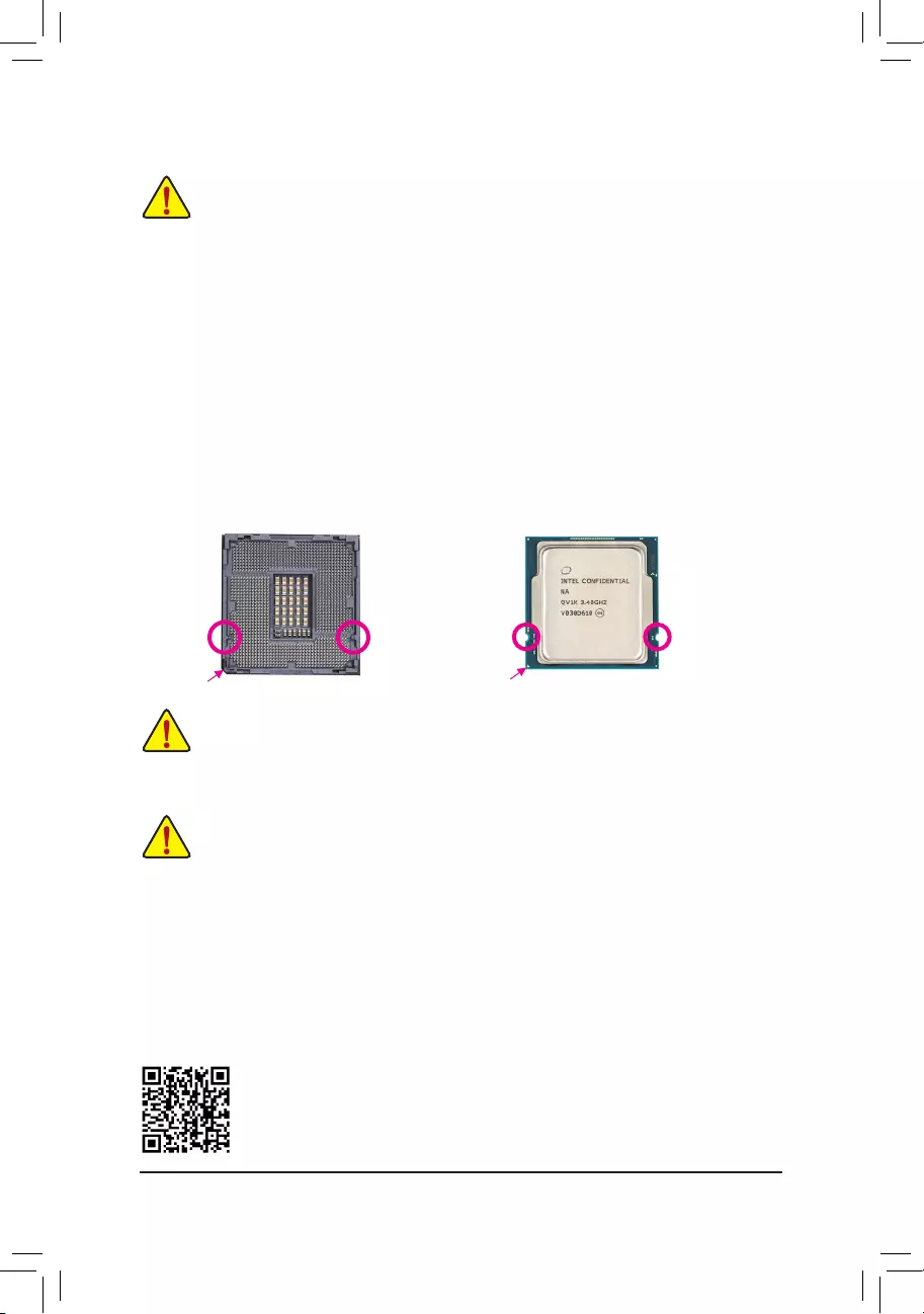
Обратите внимание на ключи выравнивания на разъеме процессора материнской платы и выемки на процессоре.
Сокет процессора LGA1200
Ключ выравнивания
Ключ выравнивания
Pin Один угол сокета ЦП
Процессор LGA1200
Отметка треугольника с выемкой на булавке XNUMX на ЦП
Notch
Не снимайте крышку гнезда ЦП до установки ЦП. Он может автоматически выскочить из загрузочной пластины после того, как вы вставите ЦП и закроете загрузочную пластину.
& Пожалуйста, посетите GIGABYTE webсайт для получения подробной информации об установке оборудования. http://www.gigabyte.com/WebСтраница/210/quick-guide.html?m=sw
— 10 —
2-4 Установка памяти
Прежде чем приступить к установке памяти, прочтите следующие рекомендации: · Убедитесь, что материнская плата поддерживает память. Рекомендуется, чтобы память о том же
емкости, марки, скорости и чипов. (Перейдите на сайт GIGABYTE webсайт для последних поддерживаемых скоростей памяти и модулей памяти.) · Всегда выключайте компьютер и отсоединяйте кабель питания от розетки перед установкой модуля памяти, чтобы предотвратить повреждение оборудования. · Модули памяти имеют надежную конструкцию. Модуль памяти можно установить только в одном направлении. Если вы не можете вставить память, измените направление. Конфигурация двухканальной памяти Эта материнская плата оснащена двумя разъемами памяти и поддерживает двухканальную технологию. После установки памяти BIOS автоматически определит характеристики и емкость памяти. Включение двухканального режима памяти удвоит исходную пропускную способность памяти. Два разъема памяти разделены на два канала, и каждый канал имеет один разъем памяти следующим образом: Канал A: DDR4_1 Канал B: DDR4_1 Из-за ограничений ЦП перед установкой памяти в двухканальном режиме прочтите следующие рекомендации. 1. Двухканальный режим нельзя включить, если установлен только один модуль памяти. 2. При включении двухканального режима с двумя модулями памяти рекомендуется использовать память одинаковой емкости, марки, скорости и микросхем.
DDR4_1 DDR4_2
— 11 —
2-5 Установка платы расширения
Прежде чем приступить к установке платы расширения, прочтите следующие рекомендации: · Убедитесь, что материнская плата поддерживает плату расширения. Внимательно прочитайте инструкцию, которая пришла
с вашей картой расширения. · Всегда выключайте компьютер и вынимайте шнур питания из розетки перед установкой
плата расширения для предотвращения повреждения оборудования. Выполните следующие действия, чтобы правильно установить карту расширения в слот расширения. 1. Найдите слот расширения, который поддерживает вашу карту. Снимите металлическую крышку слота с задней панели корпуса. 2. Совместите карту со слотом и нажмите на карту, пока она полностью не войдет в слот. 3. Убедитесь, что карта расширения полностью вошла в слот. 4. Прикрепите металлический кронштейн карты к задней панели корпуса с помощью винта. 5. После установки всех карт расширения установите на место крышки корпуса. 6. Включите компьютер. При необходимости перейдите к настройке BIOS, чтобы внести необходимые изменения в BIOS для вашего компьютера.
карты расширения). 7. Установите драйвер, прилагаемый к плате расширения, в вашей операционной системе.
Слот PCIEX16
— 12 —
2-6 Разъемы на задней панели
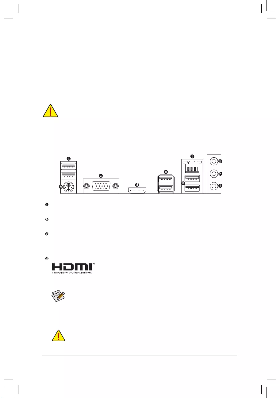
Порт USB 2.0/1.1 Порт USB поддерживает спецификацию USB 2.0/1.1. Используйте этот порт для USB-устройств. Порт PS/2 для клавиатуры/мыши
Используйте этот порт для подключения мыши или клавиатуры PS/2.
Порт D-Sub Порт D-Sub поддерживает 15-контактный разъем D-Sub и поддерживает максимальное разрешение 1920×1200 при 60 Гц (фактическое поддерживаемое разрешение зависит от используемого монитора). Подключите к этому порту монитор, поддерживающий соединение D-Sub. Порт HDMI
Порт HDMI совместим с HDCP 2.3 и поддерживает форматы Dolby TrueHD и DTS HD Master Audio. Он также поддерживает 192-канальный аудиовыход LPCM до 16 кГц/7.1 бит. Вы можете использовать этот порт для подключения монитора с поддержкой HDMI. Максимальное поддерживаемое разрешение — 4096×2160 при 30 Гц, но фактические поддерживаемые разрешения зависят от используемого монитора.
После установки устройства HDMI обязательно установите устройство воспроизведения звука по умолчанию на HDMI. (Название элемента может отличаться в зависимости от вашей операционной системы.)
Порт USB 3.2 Gen 1 Порт USB 3.2 Gen 1 поддерживает спецификацию USB 3.2 Gen 1 и совместим со спецификацией USB 2.0. Используйте этот порт для USB-устройств. Порт LAN RJ-45 Порт LAN Gigabit Ethernet обеспечивает подключение к Интернету со скоростью передачи данных до 1 Гбит/с. Ниже описаны состояния индикаторов порта LAN.
Индикатор скорости Индикатор активности Порт LAN
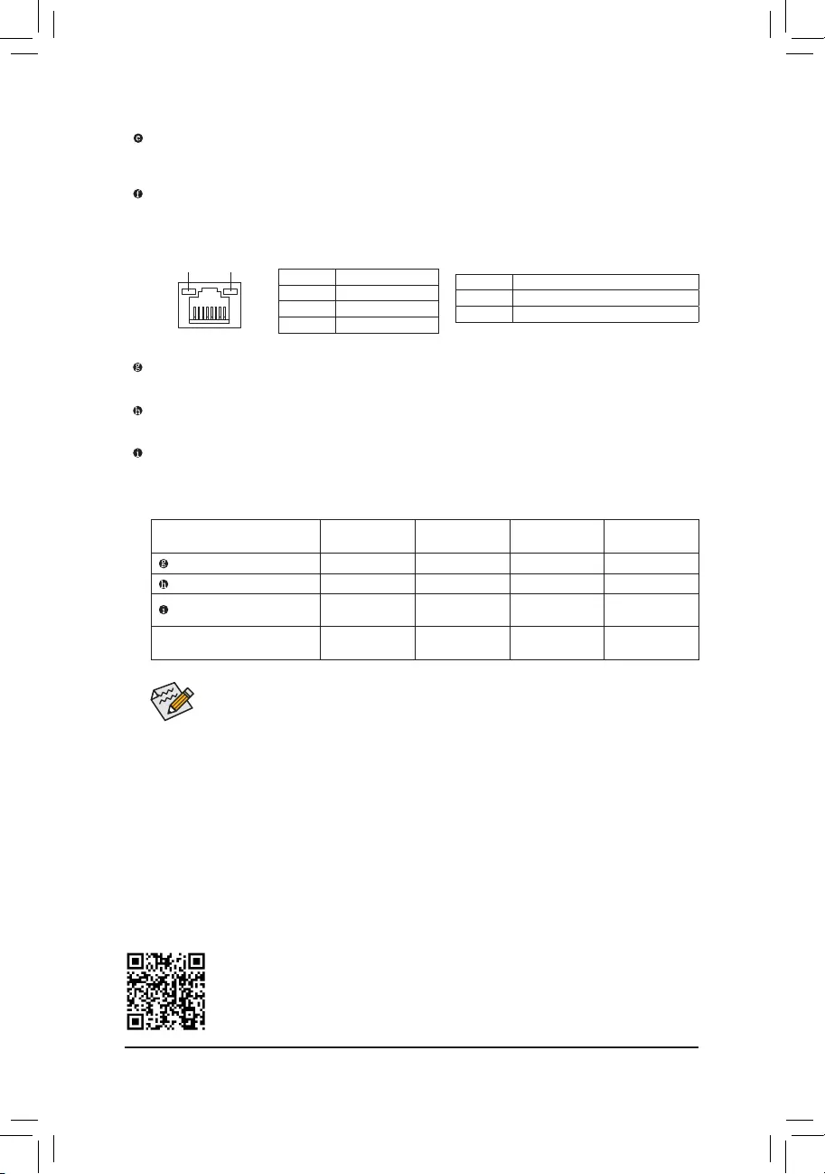
Светодиод скорости:
Состояние Оранжевый Зеленый Выкл.
Описание Скорость передачи 1 Гбит / с Скорость передачи данных 100 Мбит / с Скорость передачи данных 10 Мбит / с
Светодиод активности:
Состояние Мигает Выкл.
Описание Идет прием или передача данных. Передача или прием данных не происходит.
· При отсоединении кабеля, подключенного к разъему на задней панели, сначала отсоедините кабель от устройства, а затем отсоедините его от материнской платы.
· При отсоединении кабеля вытягивайте его прямо из разъема. Не раскачивайте его из стороны в сторону, чтобы предотвратить короткое замыкание внутри кабельного разъема.
— 13 —
Линейный вход/выход на задние динамики (синий) Гнездо линейного входа. Используйте этот аудиоразъем для линейного подключения таких устройств, как оптический привод, плеер и т. д.
Линейный выход/выход на передние динамики (зеленый) Гнездо линейного выхода.
Mic In/Center/Subwoofer Speaker Out (Розовый) Гнездо микрофонного входа.
Конфигурации аудиоразъема:
разъем
Линейный вход / выход на задний динамик
Линейный выход/выход на передние динамики Микрофонный вход/центральный/выход на сабвуфер Выход на переднюю панель Линейный выход/выход на боковые динамики
Наушники / 2 канала
a
4-канальный аа
5.1-канальный ааа
7.1-канальный аааа
Вы можете изменить функциональность аудиоразъема с помощью аудиопрограммы. Чтобы настроить 7.1-канальный звук, откройте звуковое программное обеспечение для настроек звука.
& Пожалуйста, посетите GIGABYTE webсайт для получения подробной информации о настройке аудио программного обеспечения. https://www.gigabyte.com/WebСтраница/697/realtek897-audio.html
— 14 —
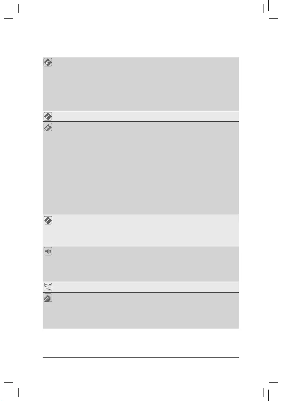
2-7 Внутренние разъемы
1
3
2 6 11 15 7
9 10 5 13 4 12
8 14
1) ATX_12V_2X4 2) ATX 3) CPU_FAN 4) SYS_FAN 5) LED_C 6) SATA3 0/1/2/3 7) M2A_SB  F_PANEL
9) F_AUDIO 10) COM 11) F_U32 12) F_USB1 13) SPI_TPM 14) CLR_CMOS 15) BAT
Перед подключением внешних устройств прочтите следующие рекомендации: · Сначала убедитесь, что ваши устройства совместимы с разъемами, которые вы хотите подключить. · Перед установкой устройств обязательно выключите устройства и компьютер. Отключите питание
шнур из розетки, чтобы не повредить устройства. · После установки устройства и перед включением компьютера убедитесь, что кабель устройства
был надежно подключен к разъему на материнской плате.
— 15 —
1/2) ATX_12V_2X4/ATX (2×4 разъема питания 12 В и 2×12 разъема основного питания) При использовании разъема питания блок питания может обеспечивать достаточное стабильное питание для всех компонентов на материнской плате. Перед подключением разъема питания сначала убедитесь, что питание отключено и все устройства правильно установлены. Разъем питания имеет надежную конструкцию. Подсоедините кабель питания к разъему питания, соблюдая правильную ориентацию. Разъем питания 12 В в основном подает питание на процессор. Если разъем питания 12 В не подключен, компьютер не запустится.
Для удовлетворения требований расширения рекомендуется использовать источник питания, способный выдерживать высокое энергопотребление (500 Вт или выше). Если используется блок питания, который не обеспечивает требуемой мощности, это может привести к нестабильной работе или невозможности загрузки системы.
5
8
1
4
ATX_12V_2X4
ATX_12V_2X4:
№ контакта Определение 1 GND (только для 2×4-контактного 12 В) 2 GND (только для 2×4-контактного 12 В) 3 GND 4 GND 5 +12 В (только для 2×4-контактного 12 В) 6 +12 В (только для для 2×4-конт. 12 В) 7 +12 В 8 +12 В
12
24
1
13
ATX
АТХ:
№ штифта 1 2 3 4 5 6 7 8 9 10 11
12
Определение
Номер контакта
3.3V
13
3.3V
14
GND
15
+ 5V
16
GND
17
+ 5V
18
GND
19
Мощность Хорошая
20
5VSB (в режиме ожидания +5В)
21
+ 12V
22
+12 В (только для 2×12-контактных разъемов 23 ATX) 3.3 В (только для 2×12-контактных разъемов 24 ATX)
Определение 3.3 В -12 В GND PS_ON (мягкое включение/выключение) GND GND GND NC +5 В +5 В +5 В (только для 2×12-контактных разъемов ATX)
GND (только для 2×12-контактных разъемов ATX)
— 16 —
3/4) CPU_FAN/SYS_FAN (Разъемы для вентиляторов) Все разъемы для вентиляторов на этой материнской плате 4-контактные. Большинство коллекторов вентиляторов имеют надежную конструкцию вставки. При подключении кабеля вентилятора убедитесь, что он подключен правильно (черный провод разъема является проводом заземления). Функция управления скоростью требует использования вентилятора с конструкцией управления скоростью вращения вентилятора. Для оптимального отвода тепла рекомендуется установить внутри корпуса системный вентилятор.
1 ЦП_ВЕНТИЛЯТОР
1 SYS_FAN
Разъем Максимальный ток Максимальная мощность
Контакт № 1 2 3 4
Определение GND Voltage Sense Control Sense Управление скоростью PWM
ЦП_ВЕНТИЛЯТОР 2А 24Вт
SYS_FAN 2А 24Вт
· Обязательно подключите кабели вентилятора к разъемам вентилятора, чтобы предотвратить перегрев процессора и системы. Перегрев может привести к повреждению процессора или зависанию системы.
· Эти разъемы для вентиляторов не являются блоками перемычек конфигурации. Не устанавливайте перемычку на разъемы.
5) LED_C (разъем для светодиодной ленты RGB) К этому разъему можно подключить стандартную светодиодную ленту 5050 RGB (12 В/G/R/B) с максимальной номинальной мощностью 2 А (12 В) и максимальной длиной 2 м.
Номер контакта Определение
1
1 12V
2G
3R
4B
Подключите светодиодную ленту RGB к разъему. Контакт питания (отмечен треугольником на вилке) светодиодной ленты должен быть подключен к контакту 1 (12 В) этого разъема. Неправильное подключение может привести к повреждению светодиодной ленты.
Светодиодная лента RGB
1 12V
Чтобы узнать, как включить/выключить светодиодную ленту, перейдите на страницу «Уникальные возможности» сайта GIGABYTE. webсайт.
Перед установкой устройств обязательно выключите устройства и компьютер. Отсоедините шнур питания от розетки, чтобы не повредить устройства.
— 17 —
6) SATA3 0/1/2/3 (разъемы SATA 6 Гбит/с) Разъемы SATA соответствуют стандарту SATA 6 Гбит/с и совместимы со стандартами SATA 3 Гбит/с и SATA 1.5 Гбит/с. Каждый разъем SATA поддерживает одно устройство SATA.
7
7
SATA3 01 23
1
1
№ штифта 1 2 3 4 5 6 7
Определение GND TXP TXN GND RXN RXP GND
Чтобы включить горячее подключение портов SATA, перейдите на страницу «Настройка BIOS» на веб-сайте GIGABYTE. webсайте и выполните поиск «Настройки портов ввода/вывода, конфигурация SATA и RST» для получения дополнительной информации.
7) M2A_SB (разъем M.2 Socket 3) Разъем M.2 поддерживает твердотельные накопители M.2 SATA или M.2 PCIe SSD.
110
80
60
42
Выполните следующие действия, чтобы правильно установить твердотельный накопитель M.2 в разъем M.2. Шаг 1. Найдите подходящее монтажное отверстие для устанавливаемого твердотельного накопителя M.2, а затем сначала установите монтажный зажим. Шаг 2: Потяните язычок зажима вверх и из монтажного отверстия. Вставьте твердотельный накопитель M.2 в разъем под углом. Шаг 3: Нажмите на твердотельный накопитель M.2, а затем закрепите его, вдавив выступ зажима в монтажное отверстие.
Замечания по установке для разъемов M.2 и SATA: Доступность разъемов SATA может зависеть от типа устройства, установленного в разъемы M.2. Разъем M.2 разделяет полосу пропускания с разъемом SATA3 3. Подробнее см. в следующей таблице.
· М2А_СБ:
Тип разъема твердотельного накопителя M.2
SATA3 0
SATA3 1
SATA3 2
SATA3 3
Твердотельный накопитель M.2 SATA
a
a
a
r
Твердотельный накопитель M.2 PCIe
a
a
a
a
Твердотельный накопитель M.2 не установлен
a
a
a
a
a: Доступно, r: Недоступно
— 18 —
F_PANEL (разъем на передней панели) Подключите к этому разъему выключатель питания, переключатель сброса, динамик, переключатель/датчик вскрытия корпуса и индикатор состояния системы на корпусе в соответствии с назначением контактов, приведенным ниже. Перед подключением кабелей обратите внимание на положительные и отрицательные контакты.
Индикатор питания Выключатель питания Динамик
ПЛЕД+ ПЛЕД-
PW+ PWSPEAK+ NC NC SPEAK-
2
20
1
19
HD+ HD-
РЕСРЕС+
ЦИКИ+
PWR_LED+ PWR_LEDPWR_LED-
Переключатель светодиодного индикатора активности сброса жесткого диска
Индикатор питания
Заголовок вскрытия корпуса
· PLED/PWR_LED (светодиод питания):
Индикатор состояния системы Подключается к индикатору состояния питания на передней панели корпуса. светодиод
S0
On
S3 / S4 / S5
от
горит, когда система работает. Светодиод не горит, когда система находится в спящем режиме S3/S4 или выключена (S5).
· PW (выключатель питания): подключается к выключателю питания на передней панели корпуса. Вы можете настроить способ выключения системы с помощью выключателя питания (перейдите на страницу «Настройка BIOS» веб-сайта GIGABYTE). webсайте и выполните поиск «SettingsPlatform Power» для получения дополнительной информации).
· SPEAK (динамик): подключается к динамику на передней панели корпуса. Система сообщает о статусе запуска системы, издавая звуковой сигнал. Один короткий звуковой сигнал будет слышен, если при запуске системы не будет обнаружено никаких проблем.
· HD (индикатор активности жесткого диска): подключается к индикатору активности жесткого диска на передней панели корпуса. Светодиод горит, когда жесткий диск считывает или записывает данные.
· RES (переключатель сброса): подключается к переключателю сброса на передней панели корпуса. Нажмите переключатель сброса, чтобы перезагрузить компьютер, если компьютер зависает и не может выполнить обычный перезапуск.
· CI (заголовок датчика вскрытия корпуса): подключается к переключателю/датчику вскрытия корпуса на корпусе, который может определять, была ли снята крышка корпуса. Для этой функции требуется шасси с переключателем/датчиком вскрытия корпуса.
· NC: нет связи.
Дизайн передней панели может отличаться в зависимости от шасси. Модуль передней панели в основном состоит из переключателя питания, переключателя сброса, индикатора питания, индикатора активности жесткого диска, динамика и т. Д. При подключении модуля передней панели корпуса к этому разъему убедитесь, что назначение проводов и контактов совпадают.
— 19 —
9) F_AUDIO (аудиоразъем на передней панели) Аудиоразъем на передней панели поддерживает звук высокой четкости (HD). К этому разъему можно подключить аудиомодуль передней панели шасси. Убедитесь, что назначение проводов разъема модуля совпадает с назначением контактов разъема материнской платы. Неправильное соединение между разъемом модуля и разъемом материнской платы приведет к невозможности работы устройства или даже к его повреждению.
9
1
10
2
Штифт № 1 2 3 4 5 6 7 8 9
10
Определение MIC L GND MIC R NC Головной телефон R Обнаружение микрофона SENSE_SEND Нет контакта Головной телефон L Обнаружение головного телефона
В некоторых корпусах имеется аудиомодуль на передней панели с отдельными разъемами на каждом проводе вместо одного штекера. Для получения информации о подключении аудиомодуля на передней панели с другим назначением проводов обратитесь к производителю шасси.
10) COM (заголовок последовательного порта) Заголовок COM может предоставлять один последовательный порт через дополнительный кабель COM-порта. Для приобретения дополнительного кабеля COM-порта обратитесь к местному дилеру.
9
1
10
2
№ штифта 1 2 3 4 5 6 7 8 9 10
Определение NDCDNSIN NSOUT NDTRGND NDSRNRTSNCTSNRINo Pin
— 20 —
11) F_U32 (заголовок USB 3.2 Gen 1) Заголовок соответствует спецификациям USB 3.2 Gen 1 и USB 2.0 и может обеспечивать два порта USB. Чтобы приобрести дополнительную 3.5-дюймовую переднюю панель с двумя портами USB 3.2 Gen 1, обратитесь к местному дилеру.
Номер контакта Определение
Номер контакта Определение
20
1
1 виртуальная шина
11 Д2+
2 SSRX1-
12 Д2-
3 SSRX1+
13 ЗЕМЛЯ
4 ЗЕМЛЯ
14 SSTX2+
5 SSTX1-
15 SSTX2-
11
10
6 SSTX1+
7 ЗЕМЛЯ
16 Земля 17 SSRX2+
8 Д1-
18 SSRX2-
9 Д1+
19 виртуальная шина
10 NC
20 Нет булавки
12) F_USB1 (заголовок USB 2.0/1.1) Заголовок соответствует спецификации USB 2.0/1.1. Каждый разъем USB может обеспечивать два порта USB через дополнительный кронштейн USB. По вопросам приобретения дополнительного кронштейна USB обращайтесь к местному дилеру.
9
1
10
2
№ штифта 1 2 3 4 5 6 7 8 9 10
Определение Питание (5 В) Питание (5 В) USB DXUSB DYUSB DX+ USB DY+ GND GND Нет контакта NC
Перед установкой скобы USB обязательно выключите компьютер и отсоедините кабель питания от розетки, чтобы не повредить скобу USB.
— 21 —
13) SPI_TPM (заголовок Trusted Platform Module) К этому заголовку можно подключить SPI TPM (Trusted Platform Module).
11
1
12
2
Номер штифта 1 2 3 4 5 6 7 8 9 10 11 12
Выходная мощность данных определения (3.3 В) No Pin NC Ввод данных CLK Выбор чипа GND IRQ NC NC RST
14) CLR_CMOS (перемычка сброса CMOS) Используйте эту перемычку для очистки конфигурации BIOS и сброса значений CMOS до заводских значений по умолчанию. Чтобы очистить значения CMOS, прикоснитесь металлическим предметом, например отверткой, к двум контактам на несколько секунд.
Открытый: Нормальный Короткий: Очистить значения CMOS
· Всегда выключайте компьютер и отсоединяйте шнур питания от розетки перед очисткой значений CMOS.
· После перезагрузки системы перейдите в BIOS Setup, чтобы загрузить заводские настройки по умолчанию (выберите Load Optimized Defaults) или вручную настройте параметры BIOS (перейдите на страницу «BIOS Setup» веб-сайта GIGABYTE). webсайт для получения дополнительной информации).
— 22 —
15) BAT (батарея) Батарея обеспечивает питание для сохранения значений (таких как конфигурация BIOS, информация о дате и времени) в CMOS, когда компьютер выключен. Замените батарею, когда уровень заряда батареиtage падает до низкого уровня, или значения CMOS могут быть неточными или могут быть потеряны.
Вы можете очистить значения CMOS, удалив батарею: 1. Выключите компьютер и отсоедините шнур питания. 2. Аккуратно извлеките аккумулятор из держателя и подождите, пока
минута. (Или используйте металлический предмет, например отвертку, чтобы коснуться положительной и отрицательной клемм держателя батареи, замкнув их на 5 секунд.) 3. Замените батарею. 4. Подсоедините шнур питания и перезагрузите компьютер. · Всегда выключайте компьютер и отсоединяйте шнур питания перед заменой батареи. · Замените батарею эквивалентной. Повреждение ваших устройств может произойти, если батарея заменена на неправильную модель. · Обратитесь по месту покупки или к местному дилеру, если вы не можете заменить аккумулятор самостоятельно или не уверены в модели аккумулятора. · При установке батареи обратите внимание на ориентацию положительной стороны (+) и отрицательной стороны (-) батареи (положительная сторона должна быть обращена вверх). · С использованными батареями необходимо обращаться в соответствии с местными экологическими нормами.
— 23 —
Глава 3 Настройка BIOS
BIOS (Basic Input and Output System) записывает аппаратные параметры системы в CMOS на материнской плате. Его основные функции включают в себя проведение самотестирования при включении питания (POST) во время запуска системы, сохранение параметров системы и загрузку операционной системы и т. д. BIOS включает программу настройки BIOS, которая позволяет пользователю изменять основные параметры конфигурации системы или активировать определенную систему. функции. Когда питание отключено, батарея на материнской плате обеспечивает необходимое питание для CMOS, чтобы сохранить значения конфигурации в CMOS. Чтобы получить доступ к программе настройки BIOS, нажмите кнопку во время POST при включении питания.
· Для обновления BIOS используйте утилиту GIGABYTE Q-Flash или @BIOS. · Q-Flash позволяет пользователю быстро и легко обновить или создать резервную копию BIOS без входа в операционную систему. · @BIOS — это утилита для Windows, которая ищет и загружает последнюю версию BIOS из Интернета.
и обновляет БИОС. Инструкции по использованию утилит Q-Flash и @BIOS см. на странице «Уникальные функции» веб-сайта GIGABYTE. webсайте и найдите «Утилиты обновления BIOS».
· Поскольку перепрошивка BIOS потенциально опасна, если вы не столкнетесь с проблемами при использовании текущей версии BIOS, рекомендуется не перепрошивать BIOS. Чтобы прошить биос, делайте это с осторожностью. Неправильная перепрошивка BIOS может привести к сбоям в работе системы.
· Рекомендуется не изменять настройки по умолчанию (если в этом нет необходимости), чтобы предотвратить нестабильность системы или другие непредвиденные результаты. Неправильное изменение настроек может привести к тому, что система не загрузится. В этом случае попробуйте очистить значения CMOS и сбросить плату до значений по умолчанию.
· См. вводную информацию о перемычке батареи/очистки CMOS в Главе 2 или перейдите на страницу «Настройка BIOS» на веб-сайте GIGABYTE. webсайте и найдите «Загрузить оптимизированные значения по умолчанию», чтобы узнать, как очистить значения CMOS.
· Меню настройки BIOS приведены только для справки и могут отличаться в зависимости от версии BIOS.
& Пожалуйста, посетите GIGABYTE webсайт для получения подробной информации о настройке BIOS Setup. https://www.gigabyte.com/WebСтраница/941/intel400-bios.html
— 24 —
Экран запуска: при загрузке компьютера появится следующий экран с логотипом запуска.
Функциональные клавиши
Функциональные клавиши: : BIOS SETUPQ-FLASH
нажмите для входа в программу настройки BIOS или для доступа к утилите Q-Flash в программе настройки BIOS. : МЕНЮ ЗАГРУЗКИ
Меню загрузки позволяет установить первое загрузочное устройство без входа в BIOS Setup. В меню загрузки используйте клавишу со стрелкой вверх или клавишу со стрелкой вниз,
— 25 —
Глава 4 Установка операционной системы и драйверов
4-1 Установка операционной системы
С правильными настройками BIOS вы готовы к установке операционной системы. Поскольку некоторые операционные системы уже включают драйвер RAID, вам не нужно устанавливать отдельный драйвер RAID в процессе установки Windows. После установки операционной системы мы рекомендуем установить все необходимые драйверы из GIGABYTE APP Center, чтобы обеспечить производительность и совместимость системы. Если устанавливаемая операционная система требует, чтобы вы предоставили дополнительный драйвер RAID в процессе установки ОС, выполните следующие действия: Шаг 1. Перейдите на веб-сайт GIGABYTE. webсайт, перейдите к модели материнской платы web страницу, загрузите драйвер Intel SATA Preinstall file на странице SupportDownloadSATA RAID/AHCI разархивируйте file и скопировать files на флэш-накопитель USB. Шаг 2: Загрузитесь с установочного диска Windows и выполните стандартные шаги установки ОС. Когда появится экран с запросом на загрузку драйвера, выберите Обзор. Шаг 3: Вставьте флэш-накопитель USB и перейдите к местоположению драйвера. Когда появится экран, как показано ниже, выберите Intel RST VMD Controller 467F и нажмите «Далее», чтобы загрузить драйвер и продолжить установку ОС.
— 26 —
4-2 Установка драйверов
После установки операционной системы в правом нижнем углу рабочего стола появится диалоговое окно с вопросом, хотите ли вы загрузить и установить драйверы и приложения GIGABYTE через APP Center. Нажмите Установить, чтобы продолжить установку. (В программе настройки BIOS убедитесь, что для параметра «Настройки IO-портов» «Конфигурация загрузки и установки APP Center» установлено значение «Включено».)
Когда появится диалоговое окно Лицензионное соглашение с конечным пользователем, нажмите для установки APP Center. На экране APP Center выберите драйверы и приложения, которые хотите установить, и нажмите «Установить».
Перед установкой убедитесь, что система подключена к Интернету. & Пожалуйста, посетите GIGABYTE webсайт для получения дополнительной информации о программном обеспечении.
https://www.gigabyte.com/WebPage/706/b560-app.html & Please visit GIGABYTE’s website for more troubleshooting information.
https://www.gigabyte.com/WebPage/351/faq.html – 27 –
Нормативные уведомления
Соединенные Штаты Америки, Заявление Федеральной комиссии связи
Заявление поставщика о соответствии 47 CFR § 2.1077 Информация о соответствии
Название продукта: Материнская плата Торговое название: GIGABYTE Номер модели: B560M H V2/H510M H
Ответственная сторона в США Контактная информация: GBT Inc. Адрес: 17358 Railroad street, City Of Industry, CA91748 Тел .: 1-626-854-9338 Контактная информация в Интернете: https://www.gigabyte.com
Заявление о соответствии требованиям FCC: Это устройство соответствует требованиям части 15 правил FCC, подраздел B, Непреднамеренные излучатели. Эксплуатация возможна при соблюдении следующих двух условий: (1) это устройство не может создавать вредных помех, и (2) это устройство должно принимать любые принимаемые помехи, включая помехи, которые могут вызвать нежелательную работу.
Это оборудование было протестировано и признано соответствующим ограничениям для цифровых устройств класса B в соответствии с частью 15 правил FCC. Эти ограничения предназначены для обеспечения разумной защиты от вредных помех при установке в жилых помещениях. Это оборудование генерирует, использует и может излучать радиочастотную энергию и, если оно не установлено и не используется в соответствии с инструкциями производителя, может создавать вредные помехи для радиосвязи. Однако нет гарантии, что помехи не возникнут в конкретной установке. Если это оборудование создает вредные помехи для радио- или телевизионного приема, что можно определить, выключив и включив оборудование, пользователю рекомендуется попытаться устранить помехи одним или несколькими из следующих способов: · Переориентировать или переместить приемное устройство антенна. · Увеличьте расстояние между оборудованием и приемником. · Подключайте оборудование к розетке в цепи, отличной от той, к которой
ресивер подключен. · Обратиться за помощью к дилеру или опытному радио / ТВ технику.
Заявление Канадского департамента связи. Это цифровое устройство не превышает пределов Класса B по излучению радиопомех от цифрового устройства, установленных в Правилах по радиопомехам Канадского департамента связи. Это цифровое устройство класса B соответствует канадскому стандарту ICES-003.
Avis de conformité à la réglementation d’Industrie Canada Cet Appareil numérique de la classe Best соответствует норме NMB-003 Канады.
Европейский Союз (ЕС) Заявление о соответствии CE Это устройство соответствует следующим директивам: Директива по электромагнитной совместимости 2014/30 / EU, Low-vol.tage Директива 2014/35/ЕС, Директива RoHS (переработанная) 2011/65/ЕС и Заявление 2015/863. Этот продукт был протестирован и признан соответствующим всем основным требованиям Директив.
Европейский союз (ЕС) Директива RoHS (переработка) 2011/65 / EU и Делегированная директива Европейской комиссии (ЕС) 2015/863 Заявление Продукты GIGABYTE не предназначены для добавления и защиты от опасных веществ (Cd, Pb, Hg, Cr + 6 , PBDE, PBB, DEHP, BBP, DBP и DIBP). Детали и компоненты были тщательно отобраны в соответствии с требованиями RoHS. Более того, мы в GIGABYTE продолжаем наши усилия по разработке продуктов, в которых не используются запрещенные на международном уровне токсичные химические вещества.
Заявление о директиве Европейского союза (ЕС) по утилизации электрического и электронного оборудования (WEEE) Компания GIGABYTE будет соблюдать национальные законы в интерпретации директивы 2012/19 / EU WEEE (переработка отходов электрического и электронного оборудования). Директива WEEE определяет обработку, сбор, переработку и утилизацию электрических и электронных устройств и их компонентов. Согласно Директиве, использованное оборудование должно быть маркировано, собрано отдельно и утилизировано надлежащим образом.
Заявление о символе WEEE Показанный ниже символ находится на продукте или его упаковке и указывает на то, что этот продукт нельзя утилизировать вместе с другими отходами. Вместо этого устройство следует доставить в центры сбора отходов для активации процедуры обработки, сбора, переработки и утилизации.
Для получения дополнительной информации о том, где вы можете сдать отработанное оборудование на переработку, обратитесь в местное правительственное учреждение, в службу утилизации бытовых отходов или в то место, где вы приобрели продукт, для получения подробной информации об экологически безопасной переработке.
Информация об аккумуляторах Европейский союз — информация об утилизации и переработке Программа утилизации GIGABYTE (доступна в некоторых регионах)
Этот символ указывает на то, что данное изделие и/или батарею нельзя утилизировать вместе с бытовыми отходами. Вы должны использовать государственную систему сбора для возврата, переработки или обработки их в соответствии с местным законодательством.
Директивы по окончанию срока службы — переработка. Показанный ниже символ находится на продукте или на его упаковке, что указывает на то, что этот продукт нельзя утилизировать вместе с другими отходами. Вместо этого устройство следует доставить в центры сбора отходов для активации процедуры обработки, сбора, переработки и утилизации.
Декларация о соответствии Директивам Европейского Союза (UE) Cet appareil portant la marque CE соответствует дополнительным директивам UE suivantes: директива Compatibilité Electromagnétique 2014/30/UE, директива Basse Tension 2014/35/UE и директива RoHS II 2011/65/УЕ. Соответствие директивам CE оценивается в соответствии с применимыми европейскими нормами.
Европейский союз (ЕС) CE-Konformitätserklärung Dieses Produkte mit CE-Kennzeichnung erfüllen folgenden EU-Richtlinien: EMV-Richtlinie 2014/30/EU, Niederspannungsrichtlinie 2014/30/EU и RoHSRichtlinie 2011/65/EU erfüllt. Die Konformität mit diesen Richtlinien wird unter Verwendung der entsprechenden Standards zurEuropäischen Normierung beurteilt.
Декларация соответствия CE Este produto com a marcação CE estão em conformidade com das seguintes Diretivas UE: Diretiva Baixa Tensão 2014/35/EU; Диретива СЕМ 2014/30/ЕС; Диретива РСП 2011/65/УЕ. Согласованность com estas diretivas é verificada utilizando as normas europeias Harmonizadas.
Декларация соответствия стандартам CE Este producto que llevan la marca CE cumplen con las siguientes Directivas de la Unión Europea: Directiva EMC (2014/30/EU), Directiva de bajo voltaje (2014/35/EU), Directiva RoHS (переработанная) (2011) /65/ЕС). El cumplimiento de estas directivas se evalúa mediante las normas europeas armonizadas.
Директива соответствия CE Этот продукт соответствует всем следующим директивам: Директива по электромагнитной совместимости 2014/30/UE, Директива по низкому напряжению 2014/35/UE, Директива RoHS (разъединенная) 2011/65/UE. Questo prodotto è stato testato e trovato conforme tutti i requisiti essenziali delle Direttive.
D33006 RoHS
— 28 —
Свяжитесь с нами
GIGA-BYTE TECHNOLOGY CO., LTD. Адрес: Baoqiang Rd., № 6, Xindian District, New Taipei City 231 TEL: +886-2-8912-4000, FAX: +886-2-8912-4005 Tech. и нетехнический. Поддержка (продажи/маркетинг): https://esupport.gigabyte.com WEB адрес (английский): https://www.gigabyte.com WEB адрес (китайский): https://www.gigabyte.com/tw
· Электронная поддержка GIGABYTE. Чтобы задать технический или нетехнический (продажи / маркетинг) вопрос, перейдите по ссылке: https://esupport.gigabyte.com
— 29 —
Документы / Ресурсы
Рекомендации

To reduce the impacts on global warming, the packaging materials of this product
are recyclable and reusable. GIGABYTE works with you to protect the environment.
For more product details, please visit GIGABYTE’s website.
H510M H
User’s Manual
Rev. 1001
Copyright
© 2021 GIGA-BYTE TECHNOLOGY CO., LTD. All rights reserved.
The trademarks mentioned in this manual are legally registered to their respective owners.
Disclaimer
Information in this manual is protected by copyright laws and is the property of GIGABYTE.
Changes to the specications and features in this manual may be made by GIGABYTE without
prior notice. No part of this manual may be reproduced, copied, translated, transmitted, or
published in any form or by any means without GIGABYTE’s prior written permission.
In order to assist in the use of this product, carefully read the User’s Manual.
For product-related information, check on our website at: https://www.gigabyte.com
Identifying Your Motherboard Revision
The revision number on your motherboard looks like this: «REV: X.X.» For example, «REV: 1.0″
means the revision of the motherboard is 1.0. Check your motherboard revision before updating
motherboard BIOS, drivers, or when looking for technical information.
Example:

— 3 —
Table of Contents
H510M H Motherboard Layout …………………………………………………………………………….4
Chapter 1 Hardware Installation ………………………………………………………………………….5
1-1 Installation Precautions ………………………………………………………………………… 5
1-2 Product Specications ………………………………………………………………………….. 6
1-3 Installing the CPU ……………………………………………………………………………….. 9
1-4 Installing the Memory …………………………………………………………………………… 9
1-5 Installing an Expansion Card ………………………………………………………………. 10
1-6 Back Panel Connectors ………………………………………………………………………. 10
1-7 Internal Connectors ……………………………………………………………………………. 12
Chapter 2 BIOS Setup ……………………………………………………………………………………..19
2-1 Startup Screen ………………………………………………………………………………….. 19
2-2 The Main Menu …………………………………………………………………………………. 20
2-3 Smart Fan 6 …………………………………………………………………………………….. 21
2-4 Favorites (F11) ………………………………………………………………………………….. 23
2-5 Tweaker ……………………………………………………………………………………………. 24
2-6 Settings ……………………………………………………………………………………………. 29
2-7 System Info. ……………………………………………………………………………………… 34
2-8 Boot …………………………………………………………………………………………………. 35
2-9 Save & Exit ……………………………………………………………………………………….. 38
Chapter 3 Appendix …………………………………………………………………………………………39
Drivers Installation ……………………………………………………………………………………….. 39
Regulatory Notices ………………………………………………………………………………………. 40
Contact Us …………………………………………………………………………………………………. 41
— 4 —
H510M H Motherboard Layout
* The box contents above are for reference only and the actual items shall depend on the product package you obtain.
The box contents are subject to change without notice.
Box Contents
5H510M H motherboard
5Motherboard driver disc 5Two SATA cables
5User’s Manual 5I/O Shield
Temperature sensor
KB_MS_
USB20 CPU_FAN
LGA1200
ATX
H510M H
AUDIO
DDR4_1
DDR4_2
BAT
ATX_12V_2X4
Intel® H510
F_U32
CODEC
CLR_CMOS
M_BIOS
VGAHDMI
USB_LAN
U32
PCIEX16
PCIEX1_1
iTE®
Super I/O
Realtek®
GbE LAN
F_PANEL
SATA3 2 0
3 1
M2A_SB
110 6080
SPI_TPM F_USB1COM
LED_C SYS_FANF_AUDIO

Chapter 1 Hardware Installation
1-1 Installation Precautions
The motherboard contains numerous delicate electronic circuits and components which can become
damaged as a result of electrostatic discharge (ESD). Prior to installation, carefully read the user’s
manual and follow these procedures:
•Prior to installation, make sure the chassis is suitable for the motherboard.
•Prior to installation, do not remove or break motherboard S/N (Serial Number) sticker or
warranty sticker provided by your dealer. These stickers are required for warranty validation.
•Always remove the AC power by unplugging the power cord from the power outlet before
installing or removing the motherboard or other hardware components.
•When connecting hardware components to the internal connectors on the motherboard, make
sure they are connected tightly and securely.
•When handling the motherboard, avoid touching any metal leads or connectors.
•It is best to wear an electrostatic discharge (ESD) wrist strap when handling electronic
components such as a motherboard, CPU or memory. If you do not have an ESD wrist strap,
keep your hands dry and rst touch a metal object to eliminate static electricity.
•Prior to installing the motherboard, please have it on top of an antistatic pad or within an
electrostatic shielding container.
•Before connecting or unplugging the power supply cable from the motherboard, make sure
the power supply has been turned off.
•Before turning on the power, make sure the power supply voltage has been set according to
the local voltage standard.
•Before using the product, please verify that all cables and power connectors of your hardware
components are connected.
•To prevent damage to the motherboard, do not allow screws to come in contact with the
motherboard circuit or its components.
•Make sure there are no leftover screws or metal components placed on the motherboard or
within the computer casing.
•Do not place the computer system on an uneven surface.
•Do not place the computer system in a high-temperature or wet environment.
•Turning on the computer power during the installation process can lead to damage to system
components as well as physical harm to the user.
•If you are uncertain about any installation steps or have a problem related to the use of the
product, please consult a certied computer technician.
•If you use an adapter, extension power cable, or power strip, ensure to consult with its installation
and/or grounding instructions.
— 5 —
1-2 ProductSpecications
CPU LGA1200 package:
— 11th Generation Intel® Core™ i9 processors/Intel® Core™ i7 processors/
Intel® Core™ i5 processors
— 10th Generation Intel® Core™ i9 processors/Intel® Core™ i7 processors/
Intel® Core™ i5 processors/Intel® Core™ i3 processors/Intel® Pentium® processors/
Intel® Celeron® processors*
* Limited to processors with 4 MB Intel® Smart Cache, Intel® Celeron® G5xx5 family.
(Go to GIGABYTE’s website for the latest CPU support list.)
L3 cache varies with CPU
Chipset Intel® H510 Express Chipset
Memory 11th Generation Intel® Core™ i9/i7/i5 processors:
— Support for DDR4 3200/3000/2933/2666/2400/2133 MHz memory modules
10th Generation Intel® Core™ i9/i7 processors:
— Support for DDR4 2933/2666/2400/2133 MHz memory modules
10th Generation Intel® Core™ i5/i3/Pentium®/Celeron® processors:
— Support for DDR4 2666/2400/2133 MHz memory modules
2 x DDR4 DIMM sockets supporting up to 64 GB (32 GB single DIMM capacity)
of system memory
Dual channel memory architecture
Support for ECC Un-buffered DIMM 1Rx8/2Rx8 memory modules (operate in
non-ECC mode)
Support for non-ECC Un-buffered DIMM 1Rx8/2Rx8/1Rx16 memory modules
Support for Extreme Memory Prole (XMP) memory modules
(Go to GIGABYTE’s website for the latest supported memory speeds and memory
modules.)
Onboard
Graphics
Integrated Graphics Processor-Intel® HD Graphics support:
— 1 x D-Sub port, supporting a maximum resolution of 1920×1200@60 Hz
— 1 x HDMI port, supporting a maximum resolution of 4096×2160@30 Hz
* Support for HDMI 1.4 version and HDCP 2.3.
(Graphics specications may vary depending on CPU support.)
Audio Realtek® Audio CODEC
High Denition Audio
2/4/5.1/7.1-channel
* To congure 7.1-channel audio, you need to open the audio software and select Device
advanced settings > Playback Device to change the default setting rst. Please visit
GIGABYTE’s website for details on conguring the audio software.
LAN Realtek® GbE LAN chip (1 Gbit/100 Mbit)
Expansion Slots 1 x PCI Express x16 slot, running at x16 (PCIEX16)
* For optimum performance, if only one PCI Express graphics card is to be installed,
be sure to install it in the PCIEX16 slot.
(The PCIEX16 slot conforms to PCI Express 4.0 standard.) (Note)
1 x PCI Express x1 slot (PCIEX1_1)
(The PCIEX1 slot conforms to PCI Express 3.0 standard.)
(Note) Supported by 11th Generation processors only.
— 6 —
Storage Interface Chipset:
— 1 x M.2 connector (Socket 3, M key, type 2260/2280/22110 SATA and PCIe
3.0 x4/x2 SSD support)
— 4 x SATA 6Gb/s connectors
* Refer to «1-7 Internal Connectors,» for the installation notices for the M.2 and SATA
connectors.
USB Chipset:
— 4 x USB 3.2 Gen 1 ports (2 ports on the back panel, 2 ports available through
the internal USB header)
— 6 x USB 2.0/1.1 ports (4 ports on the back panel, 2 ports available through
the internal USB header)
Internal
Connectors
1 x 24-pin ATX main power connector
1 x 8-pin ATX 12V power connector
1 x CPU fan header
1 x system fan header
1 x RGB LED strip header
1 x M.2 Socket 3 connector
4 x SATA 6Gb/s connectors
1 x front panel header
1 x front panel audio header
1 x USB 3.2 Gen 1 header
1 x USB 2.0/1.1 header
1 x Trusted Platform Module header (For the GC-TPM2.0 SPI/GC-TPM2.0 SPI
2.0 module only)
1 x serial port header
1 x Clear CMOS jumper
Back Panel
Connectors
1 x PS/2 keyboard/mouse port
1 x D-Sub port
1 x HDMI port
2 x USB 3.2 Gen 1 ports
4 x USB 2.0/1.1 ports
1 x RJ-45 port
3 x audio jacks
I/O Controller iTE® I/O Controller Chip
Hardware
Monitor
Voltage detection
Temperature detection
Fan speed detection
Fan fail warning
Fan speed control
* Whether the fan speed control function is supported will depend on the cooler you
install.
— 7 —
BIOS 1 x 256 Mbit ash
Use of licensed AMI UEFI BIOS
PnP 1.0a, DMI 2.7, WfM 2.0, SM BIOS 2.7, ACPI 5.0
Unique Features Support for APP Center
* Available applications in APP Center may vary by motherboard model. Supported
functions of each application may also vary depending on motherboard specications.
— @BIOS
— Ambient LED
— EasyTune
— Fast Boot
— Game Boost
— ON/OFF Charge
— Smart Backup
— System Information Viewer
Support for Q-Flash
Support for Xpress Install
Bundled
Software
Norton® Internet Security (OEM version)
Realtek® 8118 Gaming LAN Bandwidth Control Utility
Operating
System Support for Windows 10 64-bit
Form Factor Micro ATX Form Factor; 24.4cm x 21.0cm
* GIGABYTE reserves the right to make any changes to the product specications and product-related information without
prior notice.
Please visit GIGABYTE’s website
for support lists of CPU, memory
modules, SSDs, and M.2 devices.
Please visit the SupportUtility List
page on GIGABYTE’s website to
download the latest version of apps.
— 8 —
DualChannelMemoryConguration
This motherboard provides two memory sockets and supports Dual Channel Technology. After the memory
is installed, the BIOS will automatically detect the specications and capacity of the memory. Enabling Dual
Channel memory mode will double the original memory bandwidth.
Please visit GIGABYTE’s website for details on hardware installation.
1-3 Installing the CPU
Read the following guidelines before you begin to install the CPU:
•Make sure that the motherboard supports the CPU.
(Go to GIGABYTE’s website for the latest CPU support list.)
•Always turn off the computer and unplug the power cord from the power outlet before installing the
CPU to prevent hardware damage.
•Locate the pin one of the CPU. The CPU cannot be inserted if oriented incorrectly. (Or you may
locate the notches on both sides of the CPU and alignment keys on the CPU socket.)
•Apply an even and thin layer of thermal grease on the surface of the CPU.
•Do not turn on the computer if the CPU cooler is not installed, otherwise overheating and damage
of the CPU may occur.
•Set the CPU host frequency in accordance with the CPU specications. It is not recommended
that the system bus frequency be set beyond hardware specications since it does not meet the
standard requirements for the peripherals. If you wish to set the frequency beyond the standard
specications, please do so according to your hardware specications including the CPU, graphics
card, memory, hard drive, etc.
Installing the CPU
Locate the alignment keys on the motherboard CPU socket and the notches on the CPU.
Do not remove the CPU socket cover before inserting the CPU. It may pop off from the load
plate automatically during the process of re—engaging the lever after you insert the CPU.
1-4 Installing the Memory
Read the following guidelines before you begin to install the memory:
•Make sure that the motherboard supports the memory. It is recommended that memory of the same
capacity, brand, speed, and chips be used.
(Go to GIGABYTE’s website for the latest supported memory speeds and memory modules.)
•Always turn off the computer and unplug the power cord from the power outlet before installing the
memory to prevent hardware damage.
•Memory modules have a foolproof design. A memory module can be installed in only one direction.
If you are unable to insert the memory, switch the direction.
Triangle Pin One Marking on the CPU
Notch
Notch
LGA1200 CPU
Alignment
Key
Alignment
Key
LGA1200 CPU Socket
Pin One Corner of the CPU Socket
— 9 —
The two memory sockets are divided into two channels and each channel has one memory socket as following:
Channel A: DDR4_1
Channel B: DDR4_2
Due to CPU limitations, read the following guidelines before installing the memory in Dual Channel mode.
1. Dual Channel mode cannot be enabled if only one memory module is installed.
2. When enabling Dual Channel mode with two memory modules, it is recommended that memory of
the same capacity, brand, speed, and chips be used.
1-5 Installing an Expansion Card
Read the following guidelines before you begin to install an expansion card:
•Make sure the motherboard supports the expansion card. Carefully read the manual that came
with your expansion card.
•Always turn off the computer and unplug the power cord from the power outlet before installing an
expansion card to prevent hardware damage.
1-6 Back Panel Connectors
USB 2.0/1.1 Port
The USB port supports the USB 2.0/1.1 specication. Use this port for USB devices.
PS/2 Keyboard/Mouse Port
Use this port to connect a PS/2 mouse or keyboard.
D-Sub Port
The D-Sub port supports a 15-pin D-Sub connector and supports a maximum resolution of 1920×1200@60 Hz
(the actual resolutions supported depend on the monitor being used). Connect a monitor that supports
D-Sub connection to this port.
HDMI Port
The HDMI port supports HDCP 2.3 and Dolby TrueHD and DTS HD Master Audio
formats. It also supports up to 192KHz/16bit 7.1-channel LPCM audio output.
You can use this port to connect your HDMI-supported monitor. The maximum supported resolution is
4096×2160@30 Hz, but the actual resolutions supported are dependent on the monitor being used.
•When removing the cable connected to a back panel connector, rst remove the cable from
your device and then remove it from the motherboard.
•When removing the cable, pull it straight out from the connector. Do not rock it side to side to
prevent an electrical short inside the cable connector.
After installing the HDMI device, make sure to set the default sound playback device to HDMI.
(The item name may differ depending on your operating system.)
— 10 —
•You can change the functionality of an audio jack using the audio software.
•To congure 7.1-channel audio, you need to open the audio software and select Device
advanced settings > Playback Device to change the default setting rst.
Audio Jack Congurations:
Jack Headphone/
2-channel 4-channel 5.1-channel 7.1-channel
Line In/Rear Speaker Out a a a
Line Out/Front Speaker Out a a a a
Mic In/Center/Subwoofer
Speaker Out a a
Front Panel Line Out/Side
Speaker Out a
Please visit GIGABYTE’s website for details on conguring the audio software.
USB 3.2 Gen 1 Port
The USB 3.2 Gen 1 port supports the USB 3.2 Gen 1 specication and is compatible to the USB 2.0
specication. Use this port for USB devices.
RJ-45 LAN Port
The Gigabit Ethernet LAN port provides Internet connection at up to 1 Gbps data rate. The following
describes the states of the LAN port LEDs.
Line In/Rear Speaker Out (Blue)
The line in jack. Use this audio jack for line in devices such as an optical drive, walkman, etc.
Line Out/Front Speaker Out (Green)
The line out jack. Use this audio jack for a headphone or 2-channel speaker.
Mic In/Center/Subwoofer Speaker Out (Pink)
The Mic in jack.
Activity LED
Connection/
Speed LED
LAN Port
Activity LED:
Connection/Speed LED:
State Description
Orange 1 Gbps data rate
Green 100 Mbps data rate
Off 10 Mbps data rate
State Description
Blinking Data transmission or receiving is occurring
Off No data transmission or receiving is occurring
— 11 —
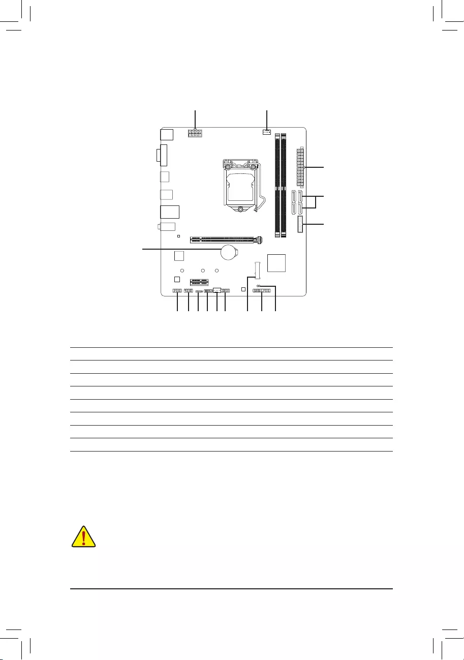
1-7 Internal Connectors
Read the following guidelines before connecting external devices:
•First make sure your devices are compliant with the connectors you wish to connect.
•Before installing the devices, be sure to turn off the devices and your computer. Unplug the power
cord from the power outlet to prevent damage to the devices.
•After installing the device and before turning on the computer, make sure the device cable has
been securely attached to the connector on the motherboard.
1) ATX_12V_2X4
2) ATX
3) CPU_FAN
4) SYS_FAN
5) LED_C
6) SATA3 0/1/2/3
7) M2A_SB
F_PANEL
9) F_AUDIO
10) F_U32
11) F_USB1
12) SPI_TPM
13) COM
14) CLR_CMOS
15) BAT
1487
10
2
6
114139
1
125
15
3
— 12 —
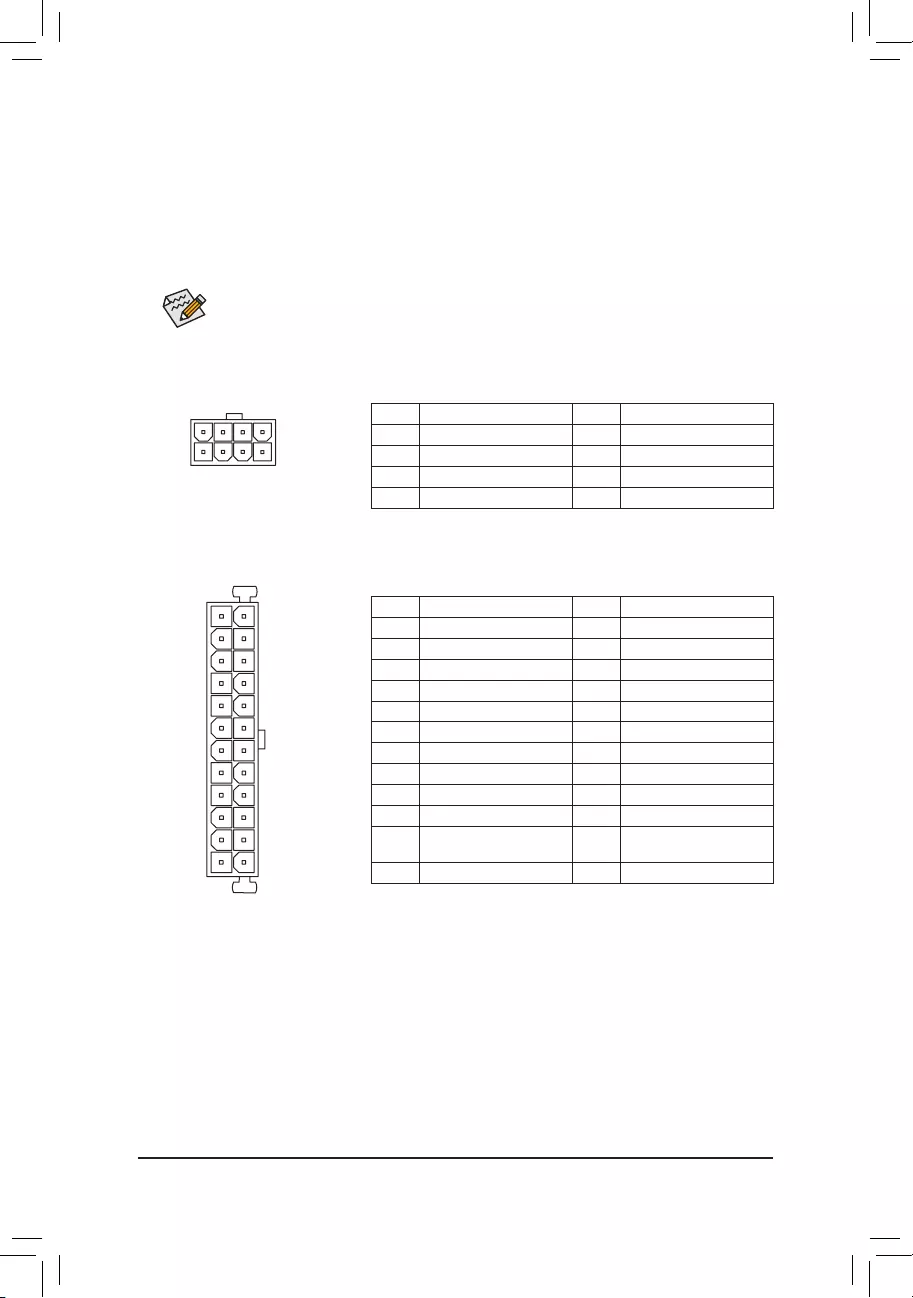
131
2412
ATX
ATX:
Pin No. Denition Pin No. Denition
1 3.3V 13 3.3V
2 3.3V 14 -12V
3 GND 15 GND
4 +5V 16 PS_ON (soft On/Off)
5 GND 17 GND
6 +5V 18 GND
7 GND 19 GND
8 Power Good 20 NC
9 5VSB (stand by +5V) 21 +5V
10 +12V 22 +5V
11 +12V (Only for 2×12-pin
ATX)
23 +5V (Only for 2×12-pin ATX)
12 3.3V (Only for 2×12-pin ATX) 24 GND (Only for 2×12-pin ATX)
ATX_12V_2X4
41
85
ATX_12V_2X4:
Pin No. Denition Pin No. Denition
1 GND (Only for 2×4-pin 12V) 5 +12V (Only for 2×4-pin 12V)
2 GND (Only for 2×4-pin 12V) 6 +12V (Only for 2×4-pin 12V)
3 GND 7 +12V
4 GND 8 +12V
1/2) ATX_12V_2X4/ATX (2×4 12V Power Connector and 2×12 Main Power Connector)
With the use of the power connector, the power supply can supply enough stable power to all the components
on the motherboard. Before connecting the power connector, rst make sure the power supply is turned
off and all devices are properly installed. The power connector possesses a foolproof design. Connect the
power supply cable to the power connector in the correct orientation.
The 12V power connector mainly supplies power to the CPU. If the 12V power connector is not connected,
the computer will not start.
To meet expansion requirements, it is recommended that a power supply that can withstand high
power consumption be used (500W or greater). If a power supply is used that does not provide the
required power, the result can lead to an unstable or unbootable system.
— 13 —
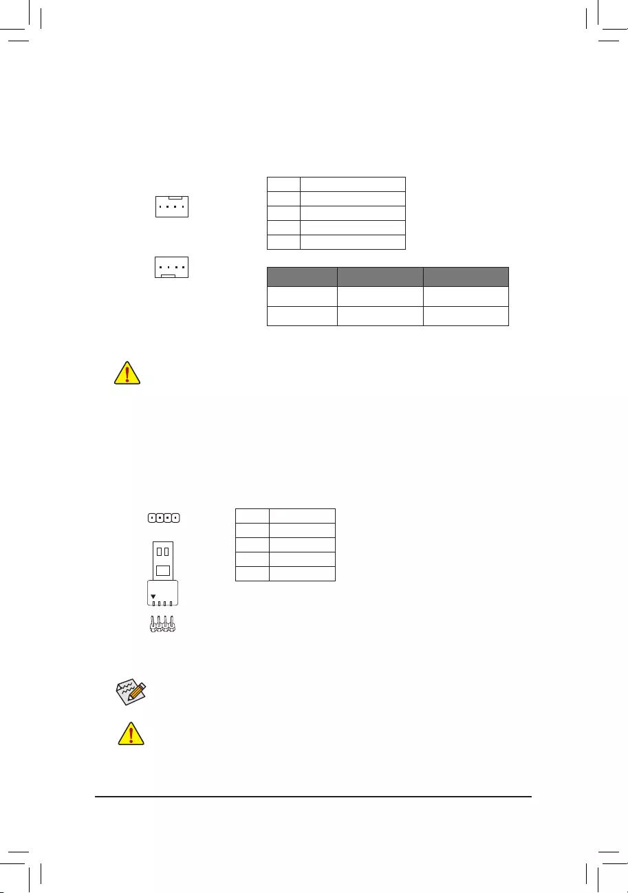
Connector CPU_FAN SYS_FAN
Maximum Current 2A 2A
Maximum Power 24W 24W
3/4) CPU_FAN/SYS_FAN (Fan Headers)
All fan headers on this motherboard are 4-pin. Most fan headers possess a foolproof insertion design.
When connecting a fan cable, be sure to connect it in the correct orientation (the black connector wire is
the ground wire). The speed control function requires the use of a fan with fan speed control design. For
optimum heat dissipation, it is recommended that a system fan be installed inside the chassis.
•Be sure to connect fan cables to the fan headers to prevent your CPU and system from
overheating. Overheating may result in damage to the CPU or the system may hang.
•These fan headers are not conguration jumper blocks. Do not place a jumper cap on the headers.
1
1
Pin No. Denition
1 GND
2 Voltage Speed Control
3 Sense
4 PWM Speed Control
CPU_FAN
SYS_FAN
5) LED_C (RGB LED Strip Header)
The header can be used to connect a standard 5050 RGB LED strip (12V/G/R/B), with maximum power
rating of 2A (12V) and maximum length of 2m.
Before installing the devices, be sure to turn off the devices and your computer. Unplug the power
cord from the power outlet to prevent damage to the devices.
For how to turn on/off the lights of the LED strip please visit the «Unique Features» webpage of
GIGABYTE’s website.
Pin No. Denition
1 12V
2 G
3 R
4 B
1
Connect your RGB LED strip to the header. The power pin (marked with a
triangle on the plug) of the LED strip must be connected to Pin 1 (12V) of
this header. Incorrect connection may lead to the damage of the LED strip.
RGB
LED Strip
1
12V
— 14 —
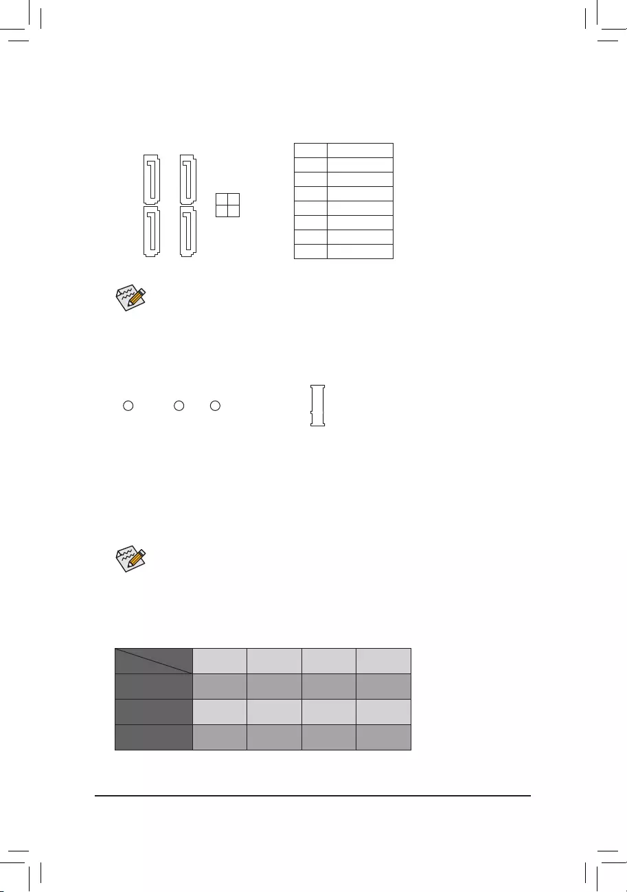
6) SATA3 0/1/2/3 (SATA 6Gb/s Connectors)
The SATA connectors conform to SATA 6Gb/s standard and are compatible with SATA 3Gb/s and SATA
1.5Gb/s standard. Each SATA connector supports a single SATA device.
Pin No. Denition
1 GND
2 TXP
3 TXN
4 GND
5 RXN
6 RXP
7 GND
To enable hot-plugging for the SATA ports, refer to Chapter 2, «BIOS Setup,» «SettingsIO Ports
SATA And RST Conguration,» for more information.
SATA3
0 1
2 3
7 7
1 1
7) M2A_SB (M.2 Socket 3 Connector)
The M.2 connector supports M.2 SATA SSDs or M.2 PCIe SSDs.
Follow the steps below to correctly install an M.2 SSD in the M.2 connector.
Step 1:
Locate the proper mounting hole for the M.2 SSD to be installed and then install the mounting clip rst.
Step 2:
Slide the M.2 SSD into the connector at an angle.
Step 3:
Press the M.2 SSD down and then secure it by pressing the clip pin into the mounting hole.
Select the proper hole for the mounting clip according to the length of the M.2 SSD to be installed.
F_USB30 F_U
B_
F_ F_
_
B
BS_
B
SB_
B
_S
S_
_
B
_U
_
B
S
123
123
123
123
1
1
1
1
BSS
S
_S
SSU
1 2 3 4 5
S3 BSSS
U
__ 3
F_USB3F
S _
S _
S _
SF
B_
B_
F
_0
S
S
_0F
_F
_
_
__B
U
S _S
_ SF_
B
USB0_B
B_
B_
F_USB3
F_USB303
_
_3U
S_
80 60110
Installation Notices for the M.2 and SATA Connectors:
The availability of the SATA connectors may be affected by the type of device installed in the M.2 sockets.
The M.2 connector shares bandwidth with the SATA3 3 connector. Refer to the following table for details.
•M2A_SB:
SATA3 0 SATA3 1 SATA3 2 SATA3 3
M.2 SATA SSD
a a a r
M.2 PCIe SSD
a a a a
No M.2 SSD Installed a a a a
a: Available, r: Not available
Connector
Type of
M.2 SSD
— 15 —
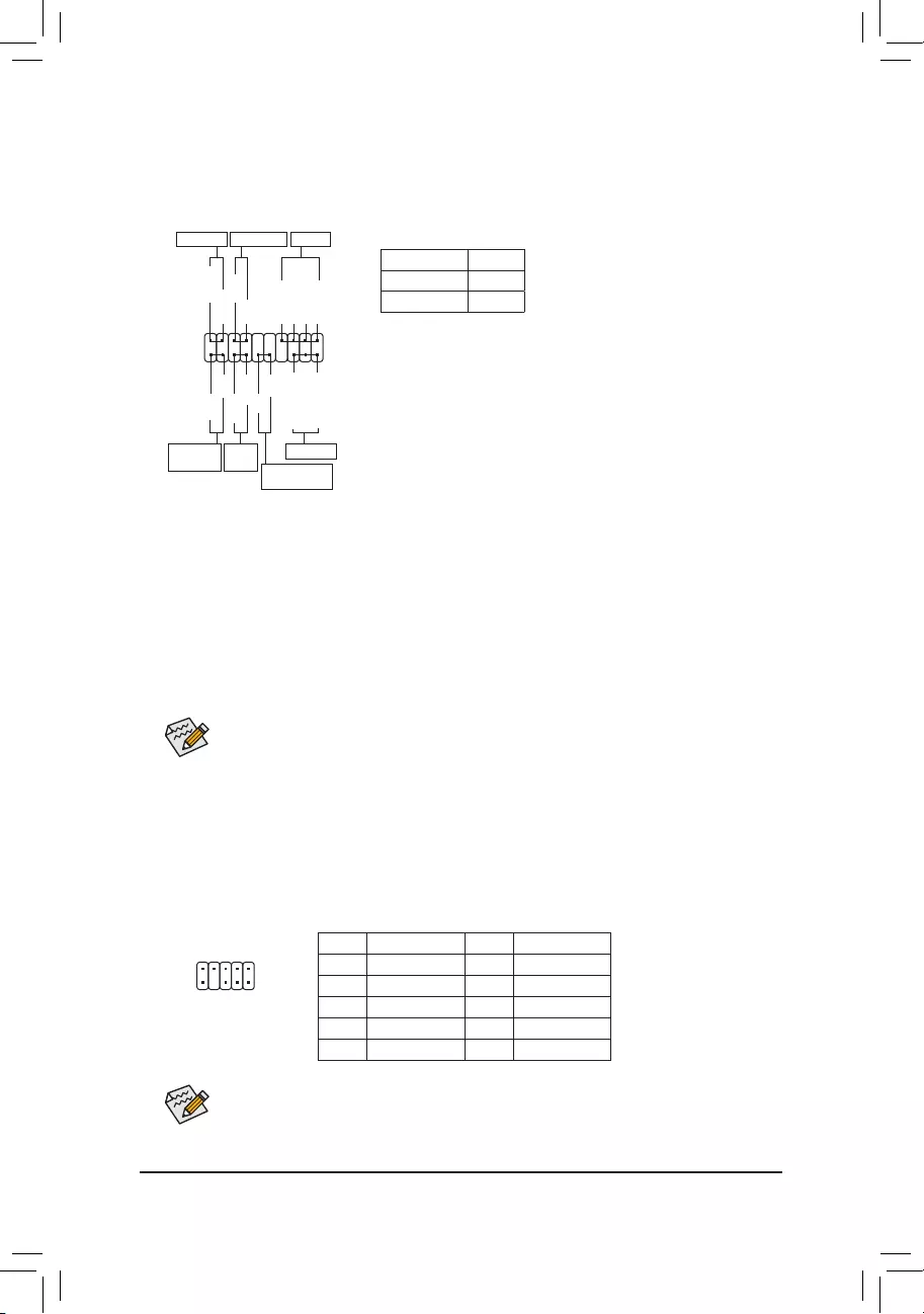
9) F_AUDIO (Front Panel Audio Header)
The front panel audio header supports High Denition audio (HD). You may connect your chassis front
panel audio module to this header. Make sure the wire assignments of the module connector match the
pin assignments of the motherboard header. Incorrect connection between the module connector and the
motherboard header will make the device unable to work or even damage it.
F_PANEL (Front Panel Header)
Connect the power switch, reset switch, speaker, chassis intrusion switch/sensor and system status indicator
on the chassis to this header according to the pin assignments below. Note the positive and negative pins
before connecting the cables.
The front panel design may differ by chassis. A front panel module mainly consists of power switch,
reset switch, power LED, hard drive activity LED, speaker and etc. When connecting your chassis
front panel module to this header, make sure the wire assignments and the pin assignments are
matched correctly.
System Status LED
S0 On
S3/S4/S5 Off
•PW (Power Switch):
Connects to the power switch on the chassis front panel. You may
congure the way to turn off your system using the power switch
(refer to Chapter 2, «BIOS Setup,» «SettingsPlatform Power,» for more
information).
•SPEAK (Speaker):
Connects to the speaker on the chassis front panel. The system reports
system startup status by issuing a beep code. One single short beep
will be heard if no problem is detected at system startup.
•PLED/PWR_LED (Power LED):
Connects to the power status indicator
on the chassis front panel. The LED is on
when the system is operating. The LED is
off when the system is in S3/S4 sleep state
or powered off (S5).
•HD (Hard Drive Activity LED):
Connects to the hard drive activity LED on the chassis front panel. The LED is on when the hard drive
is reading or writing data.
•RES (Reset Switch):
Connects to the reset switch on the chassis front panel. Press the reset switch to restart the computer
if the computer freezes and fails to perform a normal restart.
•CI (Chassis Intrusion Header):
Connects to the chassis intrusion switch/sensor on the chassis that can detect if the chassis cover has
been removed. This function requires a chassis with a chassis intrusion switch/sensor.
•NC: No connection.
Power LED
1
2
19
20
CI-
CI+
PLED-
PW-
SPEAK+
SPEAK-
PLED+
PW+
Power LED
HD-
RES+
HD+
RES-
Hard Drive
Activity LED
Reset
Switch Chassis Intrusion
Header
Power Switch Speaker
F_USB30 F_U
B_
F_ F_
_
B
BS_
B
SB_
B
_S
S_
_
B
_U
_
B
S
123
123
123
123
1
1
1
1
BSS
S
_S
SSU
1 2 3 4 5
S3 BSSS
U
__ 3
F_USB3F
S _
S _
S _
SF
B_
B_
F
_0
S
S
_0F
_F
_
_
__B
U
S _S
_ SF_
B
USB0_B
B_
B_
F_USB3
F_USB303
_
_3U
S_
PWR_LED-
PWR_LED+
PWR_LED-
NC
NC
1
2
9
10
Some chassis provide a front panel audio module that has separated connectors on each wire
instead of a single plug. For information about connecting the front panel audio module that has
different wire assignments, please contact the chassis manufacturer.
Pin No. Denition Pin No. Denition
1 MIC2_L 6 Sense
2 GND 7 FAUDIO_JD
3 MIC2_R 8 No Pin
4 NC 9 LINE2_L
5 LINE2_R 10 Sense
— 16 —
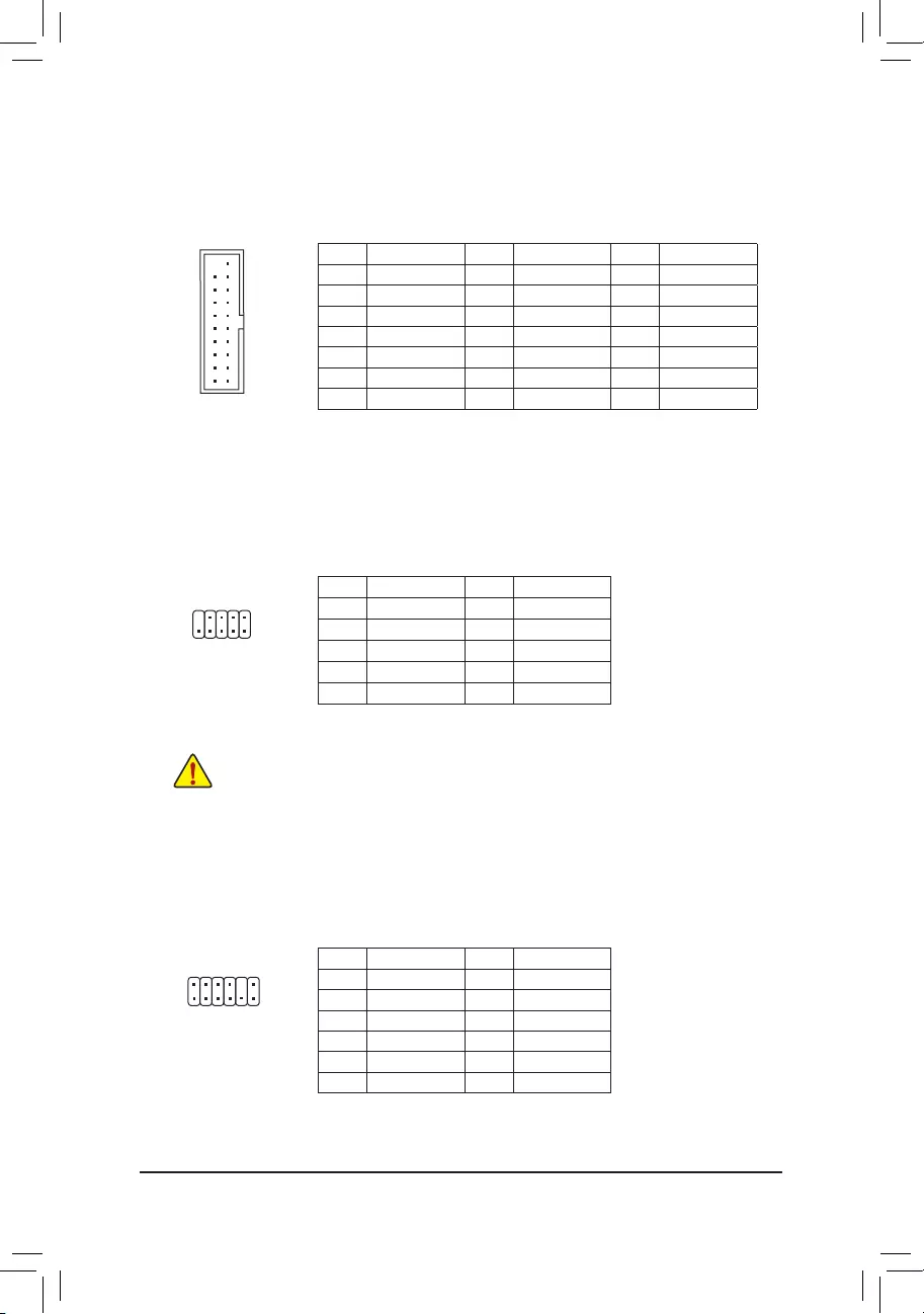
Pin No. Denition Pin No. Denition Pin No. Denition
1 VBUS 8 D1- 15 SSTX2-
2 SSRX1- 9 D1+ 16 GND
3 SSRX1+ 10 NC 17 SSRX2+
4 GND 11 D2+ 18 SSRX2-
5 SSTX1- 12 D2- 19 VBUS
6 SSTX1+ 13 GND 20 No Pin
7 GND 14 SSTX2+
10) F_U32 (USB 3.2 Gen 1 Header)
The header conforms to USB 3.2 Gen 1 and USB 2.0 specication and can provide two USB ports. For
purchasing the optional 3.5″ front panel that provides two USB 3.2 Gen 1 ports, please contact the local
dealer.
F_USB30 F_U
B_
F_ F_
_
B
BS_
B
SB_
B
_S
S_
_
B
_U
_
B
S
123
123
123
123
1
1
1
1
BSS
S
_S
SSU
1 2 3 4 5
S3 BSSS
U
__ 3
F_USB3F
S _
S _
S _
SF
B_
B_
F
_0
S
S
_0F
_F
_
_
__B
U
S _S
_ SF_
B
USB0_B
B_
B_
F_USB3
F_USB303
_
_3U
S_
10
20 1
11
11) F_USB1 (USB 2.0/1.1 Header)
The header conforms to USB 2.0/1.1 specication. Each USB header can provide two USB ports via an
optional USB bracket. For purchasing the optional USB bracket, please contact the local dealer.
Pin No. Denition Pin No. Denition
1 Power (5V) 6 USB DY+
2 Power (5V) 7 GND
3 USB DX- 8 GND
4 USB DY— 9 No Pin
5 USB DX+ 10 NC
•Do not plug the IEEE 1394 bracket (2×5-pin) cable into the USB 2.0/1.1 header.
•Prior to installing the USB bracket, be sure to turn off your computer and unplug the power cord
from the power outlet to prevent damage to the USB bracket.
10
9
2
1
12) SPI_TPM (Trusted Platform Module Header)
You may connect an SPI TPM (Trusted Platform Module) to this header.
Pin No. Denition Pin No. Denition
1Data Output 7Chip Select
2Power (3.3V) 8GND
3No Pin 9IRQ
4NC 10 NC
5Data Input 11 NC
6CLK 12 RST
12
11
2
1
F_USB30 F_U
B_
F_ F_
_
B
BS_
B
SB_
B
_S
S_
_
B
_U
_
B
S
123
123
123
123
1
1
1
1
BSS
S
_S
SSU
1 2 3 4 5
S3 BSSS
U
__ 3
F_USB3F
S _
S _
S _
SF
B_
B_
F
_0
S
S
_0F
_F
_
_
__B
U
S _S
_ SF_
B
USB0_B
B_
B_
F_USB3
F_USB303
_
_3U
S_
— 17 —
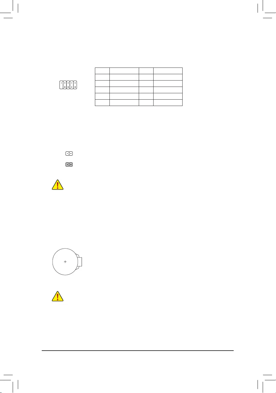
13) COM (Serial Port Header)
The COM header can provide one serial port via an optional COM port cable. For purchasing the optional
COM port cable, please contact the local dealer.
Pin No. Denition Pin No. Denition
1 NDCD- 6 NDSR-
2 NSIN 7 NRTS-
3 NSOUT 8 NCTS-
4 NDTR- 9 NRI-
5 GND 10 No Pin
1
2
9
10
14) CLR_CMOS (Clear CMOS Jumper)
Use this jumper to clear the BIOS conguration and reset the CMOS values to factory defaults. To clear
the CMOS values, use a metal object like a screwdriver to touch the two pins for a few seconds.
•Always turn off your computer and unplug the power cord from the power outlet before clearing
the CMOS values.
•After system restart, go to BIOS Setup to load factory defaults (select Load Optimized Defaults) or
manually congure the BIOS settings (refer to Chapter 2, «BIOS Setup,» for BIOS congurations).
Open: Normal
Short: Clear CMOS Values
15) BAT (Battery)
The battery provides power to keep the values (such as BIOS congurations, date, and time information)
in the CMOS when the computer is turned off. Replace the battery when the battery voltage drops to a low
level, or the CMOS values may not be accurate or may be lost.
You may clear the CMOS values by removing the battery:
1. Turn off your computer and unplug the power cord.
2. Gently remove the battery from the battery holder and wait for one minute. (Or use a metal
object like a screwdriver to touch the positive and negative terminals of the battery holder,
making them short for 5 seconds.)
3. Replace the battery.
4. Plug in the power cord and restart your computer.
•Always turn off your computer and unplug the power cord before replacing the battery.
•Replace the battery with an equivalent one. Damage to your devices may occur if the battery
is replaced with an incorrect model.
•Contact the place of purchase or local dealer if you are not able to replace the battery by yourself
or uncertain about the battery model.
•When installing the battery, note the orientation of the positive side (+) and the negative side
(-) of the battery (the positive side should face up).
•Used batteries must be handled in accordance with local environmental regulations.
— 18 —
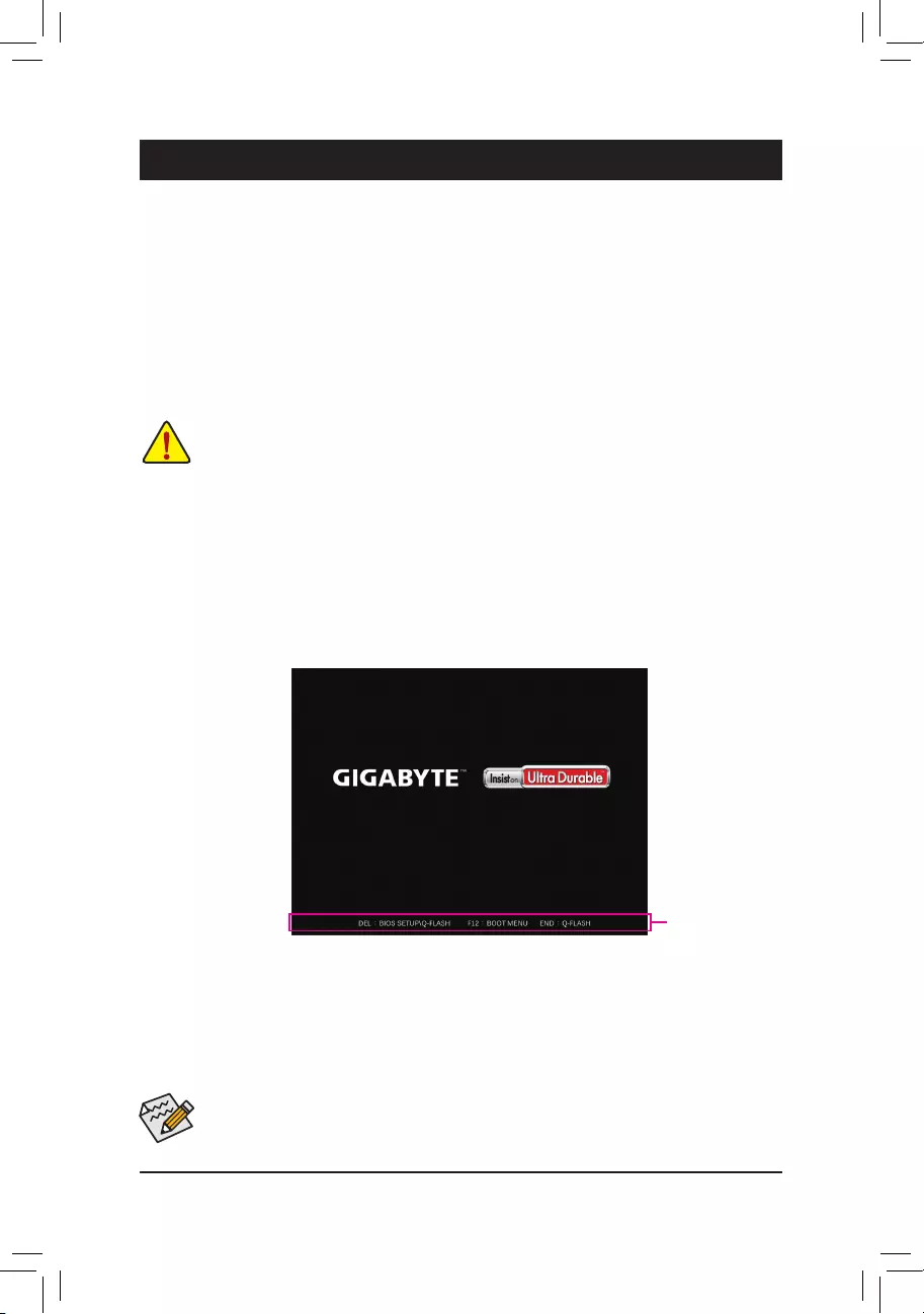
Chapter 2 BIOS Setup
BIOS (Basic Input and Output System) records hardware parameters of the system in the CMOS on the
motherboard. Its major functions include conducting the Power-On Self-Test (POST) during system startup,
saving system parameters and loading operating system, etc. BIOS includes a BIOS Setup program that allows
the user to modify basic system conguration settings or to activate certain system features.
When the power is turned off, the battery on the motherboard supplies the necessary power to the CMOS to
keep the conguration values in the CMOS.
To access the BIOS Setup program, press the <Delete> key during the POST when the power is turned on.
To upgrade the BIOS, use either the GIGABYTE Q-Flash or @BIOS utility.
•Q-Flash allows the user to quickly and easily upgrade or back up BIOS without entering the operating system.
•@BIOS is a Windows-based utility that searches and downloads the latest version of BIOS from the Internet
and updates the BIOS.
•Because BIOS ashing is potentially risky, if you do not encounter problems using the current version of BIOS,
it is recommended that you not ash the BIOS. To ash the BIOS, do it with caution. Inadequate BIOS ashing
may result in system malfunction.
•It is recommended that you not alter the default settings (unless you need to) to prevent system instability or other
unexpected results. Inadequately altering the settings may result in system’s failure to boot. If this occurs, try to
clear the CMOS values and reset the board to default values. (Refer to the «Load Optimized Defaults» section in
this chapter or introductions of the battery/clear CMOS jumper in Chapter 1 for how to clear the CMOS values.)
Function Keys
•When the system is not stable as usual, select the Load Optimized Defaults item to set your system to its defaults.
•The BIOS Setup menus described in this chapter are for reference only and may differ by BIOS version.
There are two different BIOS modes as follows and you can use the <F2> key to switch between the two modes.
Easy Mode allows users to quickly view their current system information or to make adjustments for optimum
performance. In Easy Mode, you can use your mouse to move through conguration items. The Advanced Mode
provides detailed BIOS settings. You can press the arrow keys on your keyboard to move among the items
and press <Enter> to accept or enter a sub-menu. Or you can use your mouse to select the item you want.
2-1 Startup Screen
The following startup Logo screen will appear when the computer boots.
— 19 —
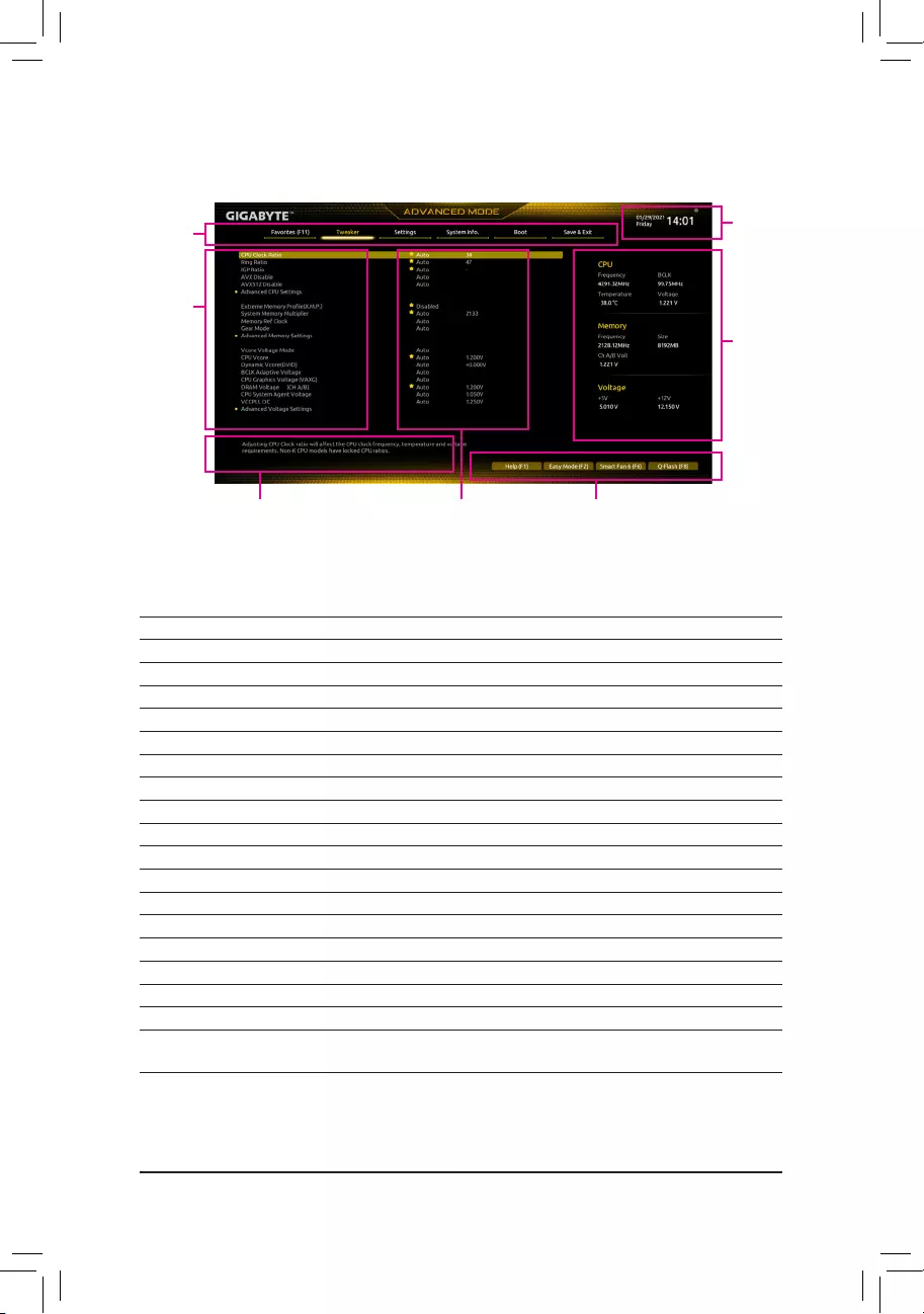
2-2 The Main Menu
Advanced Mode Function Keys
<f><g> Move the selection bar to select a setup menu
<h><i>Move the selection bar to select an conguration item on a menu
<Enter>/Double Click Execute command or enter a menu
<+>/<Page Up> Increase the numeric value or make changes
<—>/<Page Down> Decrease the numeric value or make changes
<F1> Show descriptions of the function keys
<F2> Switch to Easy Mode
<F3> Save the current BIOS settings to a prole
<F4> Load the BIOS settings from a prole created before
<F5> Restore the previous BIOS settings for the current submenus
<F6> Display the Smart Fan 6 screen
<F7> Load the Optimized BIOS default settings for the current submenus
<F8> Access the Q-Flash utility
<F10> Save all the changes and exit the BIOS Setup program
<F11> Switch to the Favorites submenu
<F12> Capture the current screen as an image and save it to your USB drive
<Insert> Add or remove a favorite option
<Ctrl>+<S> Display information on the installed memory
<Esc> Main Menu: Exit the BIOS Setup program
Submenus: Exit current submenu
Hardware
Information
Option Description Current Settings
Setup Menus System Time
Quick Access Bar allows you to quickly move to
the General Help, Easy Mode, Smart Fan 6, or
Q-Flash screen.
Conguration
Items
— 20 —
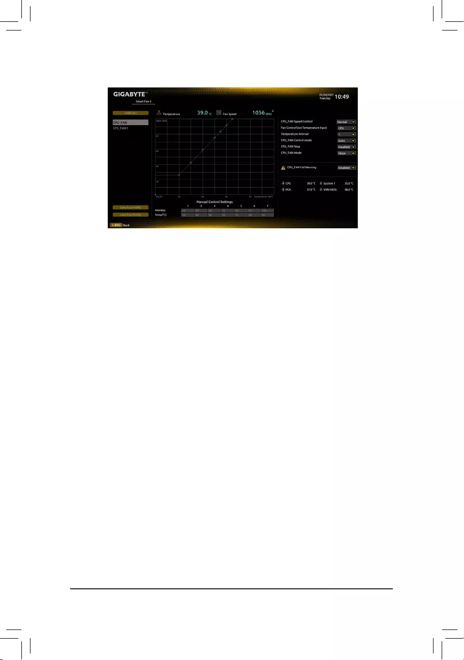
Use the <F6> function key to quickly switch to this screen. This screen allows you to congure fan speed related
settings for each fan header or monitor your system/CPU temperature.
&TUNE ALL
Allows you to apply the current settings to all fan headers.
&Temperature
Displays the current temperature of the selected target area.
&Fan Speed
Displays current fan speeds.
&Fan Speed Control
Allows you to determine whether to enable the fan speed control function and adjust the fan speed.
Normal Allows the fan to run at different speeds according to the temperature. You can adjust
the fan speed with System Information Viewer based on your system requirements.
(Default)
Silent Allows the fan to run at slow speeds.
Manual Allows you to drag the curve nodes to adjust fan speed. Or you can use the EZ Tuning
feature. After adjusting the node position, press Apply to automatically calculate the
slope of the curve.
Full Speed Allows the fan to run at full speeds.
&Fan Control Use Temperature Input
Allows you to select the reference temperature for fan speed control.
&Temperature Interval
Allows you to select the temperature interval for fan speed change.
&FAN Control Mode
Auto Lets the BIOS automatically detect the type of fan installed and sets the optimal control
mode. (Default)
Voltage Voltage mode is recommended for a 3-pin fan.
PWM PWM mode is recommended for a 4-pin fan.
&FAN Stop
Enables or disables the fan stop function. You can set the temperature limit using the temperature curve.
The fan stops operation when the temperature is lower than the limit. (Default: Disabled)
2-3 Smart Fan 6
— 21 —

&FAN Mode
Allows you to set the operating mode for the fan.
Slope Adjusts the fan speed linearly based on the temperature. (Default)
Stair Adjusts the fan speed stepwise based on the temperature.
&FAN Fail Warning
Allows the system to emit warning sound if the fan is not connected or fails. Check the fan condition or fan
connection when this occurs. (Default: Disabled)
&SaveFanProle
This function allows you to save the current settings to a prole. You can save the prole in the BIOS or
select Select File in HDD/FDD/USB to save the prole to your storage device.
&LoadFanProle
This function allows you to load a previously saved BIOS prole without the hassles of reconguring the
BIOS settings. Or you can select Select File in HDD/FDD/USB to load a prole from your storage device.
— 22 —

2-4 Favorites (F11)
Set your frequently used options as your favorites and use the <F11> key to quickly switch to the page where
all of your favorite options are located. To add or remove a favorite option, go to its original page and press
<Insert> on the option. The option is marked with a star sign if set as a «favorite.»
— 23 —
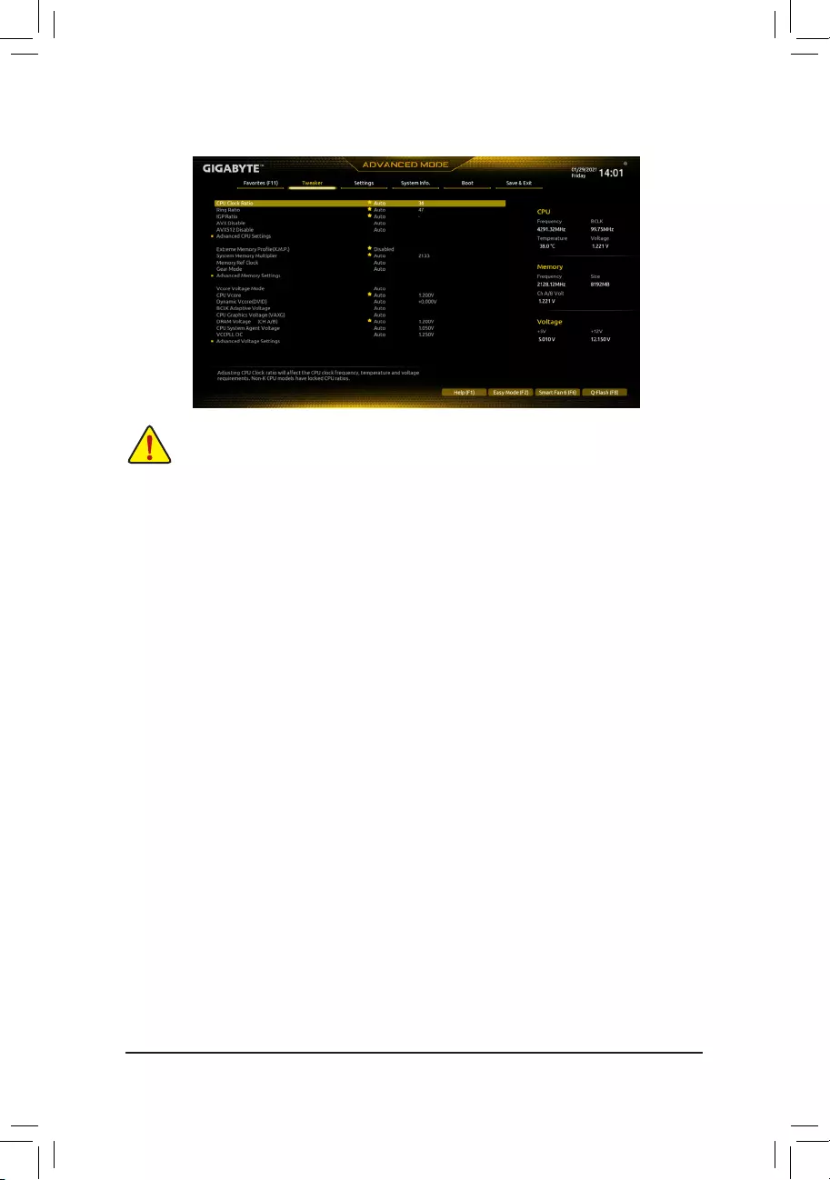
&CPU Clock Ratio
Allows you to alter the clock ratio for the installed CPU. The adjustable range is dependent on the CPU
being installed.
&Ring Ratio
Allows you to set the CPU Uncore ratio. The adjustable range is dependent on the CPU being used. (Default:
Auto)
&IGP Ratio (Note)
Allows you to set the Graphics Ratio. (Default: Auto)
&AVX Disable (Note)
Allows you to disable the AVX instruction sets on a CPU that supports AVX. (Default: Auto)
&AVX512 Disable (Note)
Allows you to disable the AVX-512 instruction sets on a CPU that supports AVX-512. (Default: Auto)
Advanced CPU Settings
&Core Fused Max Core Ratio (Note)
Displays the highest frequency of each core.
&CPU Over Temperature Protection (Note)
Allows you to ne-tune the TJ Max offset value. (Default: Auto)
&FCLK Frequency for Early Power On (Note)
Allows you to set the FCLK frequency. Options are: Normal(800Mhz), 1GHz, 400MHz. (Default: 1GHz)
&Hyper-Threading Technology
Allows you to determine whether to enable multi-threading technology when using an Intel® CPU that
supports this function. This feature only works for operating systems that support multi-processor mode.
Auto lets the BIOS automatically congure this setting. (Default: Auto)
(Note) This item is present only when you install a CPU that supports this feature. For more information about
Intel® CPUs’ unique features, please visit Intel’s website.
Whether the system will work stably with the overclock/overvoltage settings you made is dependent on your overall
system congurations. Incorrectly doing overclock/overvoltage may result in damage to CPU, chipset, or memory
and reduce the useful life of these components. This page is for advanced users only and we recommend you not to
alter the default settings to prevent system instability or other unexpected results. (Inadequately altering the settings
may result in system’s failure to boot. If this occurs, clear the CMOS values and reset the board to default values.)
2-5 Tweaker
— 24 —

&No. of CPU Cores Enabled
Allows you to select the number of CPU cores to enable in an Intel® multi-core CPU (the number of CPU
cores may vary by CPU). Auto lets the BIOS automatically congure this setting. (Default: Auto)
&Intel(R) Speed Shift Technology (Intel® Speed Shift Technology) (Note)
Enables or disables Intel® Speed Shift Technology. Enabling this feature allows the processor to ramp up
its operating frequency more quickly and then improves the system responsiveness. (Default: Enabled)
&CPU Thermal Monitor (Note)
Enables or disables Intel® Thermal Monitor function, a CPU overheating protection function. When enabled,
the CPU core frequency and voltage will be reduced when the CPU is overheated. Auto lets the BIOS
automatically congure this setting. (Default: Auto)
&Ring to Core offset (Down Bin)
Allows you to determine whether to disable the CPU Ring ratio auto-down function. Auto lets the BIOS
automatically congure this setting. (Default: Auto)
&CPU EIST Function (Note)
Enables or disables Enhanced Intel® Speed Step Technology (EIST). Depending on CPU loading, Intel®
EIST technology can dynamically and effectively lower the CPU voltage and core frequency to decrease
average power consumption and heat production. Auto lets the BIOS automatically congure this setting.
(Default: Auto)
&Race To Halt (RTH) (Note)/EnergyEfcientTurbo (Note)
Enables or disables the CPU power saving related settings. (Default: Auto)
&Intel(R) Turbo Boost Technology (Note)
Allows you to determine whether to enable the Intel® CPU Turbo Boost technology. Auto lets the BIOS
automatically congure this setting. (Default: Auto)
&Intel(R) Turbo Boost Max Technology 3.0 (Note)
Enables or disables Intel® Turbo Boost Max Technology 3.0. Intel® Turbo Boost Max Technology 3.0 allows
the system to identify the processor’s best performance core and lets you manually direct the most critical
workloads to it. You can even adjust the frequency of each core individually for performance optimization.
(Default: Enabled)
&CPU Flex Ratio Override
Enables or disables the CPU Flex Ratio. The maximum CPU clock ratio will be based on the CPU Flex
Ratio Settings value if CPU Clock Ratio is set to Auto. (Default: Disabled)
&CPU Flex Ratio Settings
Allows you to set the CPU Flex Ratio. The adjustable range may vary by CPU.
&Frequency Clipping TVB (Note)
Allows you to enable or disable automatic CPU frequency reduction initiated by Thermal Velocity Boost.
Auto lets the BIOS automatically congure this setting. (Default: Auto)
&Voltage reduction initiated TVB (Note)
Allows you to enable or disable automatic CPU voltage reduction initiated by Thermal Velocity Boost. Auto
lets the BIOS automatically congure this setting. (Default: Auto)
dActive Turbo Ratios
&Turbo Ratio (Core Active)
Allows you to set the CPU Turbo ratios for different number of active cores. Auto sets the CPU Turbo ratios
according to the CPU specications. This item is congurable only when Active Turbo Ratios is set to
Manual. (Default: Auto)
(Note) This item is present only when you install a CPU that supports this feature. For more information about
Intel® CPUs’ unique features, please visit Intel’s website.
— 25 —

dC-States Control
&CPU Enhanced Halt (C1E)
Enables or disables Intel
®
CPU Enhanced Halt (C1E) function, a CPU power-saving function in system halt state.
When enabled, the CPU core frequency and voltage will be reduced during system halt state to decrease
power consumption. Auto lets the BIOS automatically congure this setting. This item is congurable only
when C-States Control is set to Enabled. (Default: Auto)
&C3 State Support (Note)
Allows you to determine whether to let the CPU enter C3 mode in system halt state. When enabled, the
CPU core frequency and voltage will be reduced during system halt state to decrease power consumption.
The C3 state is a more enhanced power-saving state than C1. Auto lets the BIOS automatically congure
this setting. This item is congurable only when C-States Control is set to Enabled. (Default: Auto)
&C6/C7 State Support
Allows you to determine whether to let the CPU enter C6/C7 mode in system halt state. When enabled, the
CPU core frequency and voltage will be reduced during system halt state to decrease power consumption.
The C6/C7 state is a more enhanced power-saving state than C3. Auto lets the BIOS automatically congure
this setting. This item is congurable only when C-States Control is set to Enabled. (Default: Auto)
&C8 State Support (Note)
Allows you to determine whether to let the CPU enter C8 mode in system halt state. When enabled, the CPU
core frequency and voltage will be reduced during system halt state to decrease power consumption. The
C8 state is a more enhanced power-saving state than C6/C7. Auto lets the BIOS automatically congure
this setting. This item is congurable only when C-States Control is set to Enabled. (Default: Auto)
&C10 State Support (Note)
Allows you to determine whether to let the CPU enter C10 mode in system halt state. When enabled, the
CPU core frequency and voltage will be reduced during system halt state to decrease power consumption.
The C10 state is a more enhanced power-saving state than C8. Auto lets the BIOS automatically congure
this setting. This item is congurable only when C-States Control is set to Enabled. (Default: Auto)
&Package C State limit (Note)
Allows you to specify the C-state limit for the processor. Auto lets the BIOS automatically congure this
setting. This item is congurable only when C-States Control is set to Enabled. (Default: Auto)
&CPU Power Performance (Note)
Allows you to determine whether to increase CPU performance. (Default: Auto)
dTurbo Power Limits
Allows you to set a power limit for CPU Turbo mode. When the CPU power consumption exceeds the
specied power limit, the CPU will automatically reduce the core frequency in order to reduce the power.
Auto sets the power limit according to the CPU specications. (Default: Auto)
&Power Limit TDP (Watts) / Power Limit Time
Allows you to set the power limit for CPU/platform/memory Turbo mode and how long it takes to operate
at the specied power limit. Auto sets the power limit according to the CPU specications. This item is
congurable only when Turbo Power Limits is set to Enabled. (Default: Auto)
&Core Current Limit (Amps)
Allows you to set a current limit for CPU Turbo mode. When the CPU current exceeds the specied current
limit, the CPU will automatically reduce the core frequency in order to reduce the current. Auto sets the
power limit according to the CPU specications. This item is congurable only when Turbo Power Limits
is set to Enabled. (Default: Auto)
(Note) This item is present only when you install a CPU that supports this feature. For more information about
Intel® CPUs’ unique features, please visit Intel’s website.
— 26 —

dTurbo Per Core Limit Control (Note 1)
Allows you to control each CPU core limit separately. (Default: Auto)
&ExtremeMemoryProle(X.M.P.) (Note 2)
Allows the BIOS to read the SPD data on XMP memory module(s) to enhance memory performance when
enabled.
Disabled Disables this function. (Default)
Prole1 Uses Prole 1 settings.
Prole2 (Note 2) Uses Prole 2 settings.
&System Memory Multiplier
Allows you to set the system memory multiplier. Auto sets memory multiplier according to memory SPD
data. (Default: Auto)
&Memory Ref Clock
Allows you to manually adjust the memory reference clock. (Default: Auto)
&Memory Odd Ratio (100/133 or 200/266) (Note 2)
Enabled allows Qclk to run in odd frequency. (Default: Auto)
&Gear Mode (Note 2)
Allows you to improve the maximum OC frequency potential. (Default: Auto)
Advanced Memory Settings
&Memory Multiplier Tweaker
Provides different levels of memory auto-tuning. (Default: Auto)
&Channel Interleaving
Enables or disables memory channel interleaving. Enabled allows the system to simultaneously access
different channels of the memory to increase memory performance and stability. Auto lets the BIOS
automatically congure this setting. (Default: Auto)
&Rank Interleaving
Enables or disables memory rank interleaving. Enabled allows the system to simultaneously access different
ranks of the memory to increase memory performance and stability. Auto lets the BIOS automatically
congure this setting. (Default: Auto)
&Memory Boot Mode
Provides memory detection and training methods.
Auto Lets the BIOS automatically congure this setting. (Default)
Normal The BIOS automatically performs memory training. Please note that if the system
becomes unstable or unbootable, try to clear the CMOS values and reset the board
to default values. (Refer to the introductions of the battery/clear CMOS jumper in
Chapter 1 for how to clear the CMOS values.)
Enable Fast Boot Skip memory detection and training in some specic criteria for faster memory
boot.
Disable Fast Boot Detect and train memory at every single boot.
&Realtime Memory Timing
Allows you to ne-tune memory timings after the BIOS stage. (Default: Auto)
(Note 1) This item is present only when you install a CPU that supports this feature. For more information about
Intel® CPUs’ unique features, please visit Intel’s website.
(Note 2) This item is present only when you install a CPU and a memory module that support this feature.
— 27 —

&Memory Enhancement Settings
Provides several memory performance enhancement settings: Auto, Relax OC, Enhanced Stability, Normal,
Enhanced Performance, High Frequency, High Density, and DDR-4500+. (Default: Auto)
&Memory Channel Detection Message
Allows you to determine whether to show an alert message when the memory is not installed in the optimal
memory channel. (Default: Enabled)
SPD Info
Displays information on the installed memory.
Memory Channels Timings
d Channels Standard Timing Control, Channels Advanced Timing Control, Channels
Misc Timing Control
These sections provide memory timing settings. Note: Your system may become unstable or fail to boot
after you make changes on the memory timings. If this occurs, please reset the board to default values by
loading optimized defaults or clearing the CMOS values.
& Vcore Volatge Mode/CPU Vcore/Dynamic Vcore(DVID)/BCLK Adaptive Voltage/CPU
Graphics Voltage (VAXG)/DRAM Voltage (CH A/B)/CPU System Agent Voltage/VCCPLL OC
These items allow you to adjust the CPU Vcore and memory voltages.
Advanced Voltage Settings
This submenu allows you to congure Load-Line Calibration level, over-voltage protection level, and over-
current protection level.
— 28 —
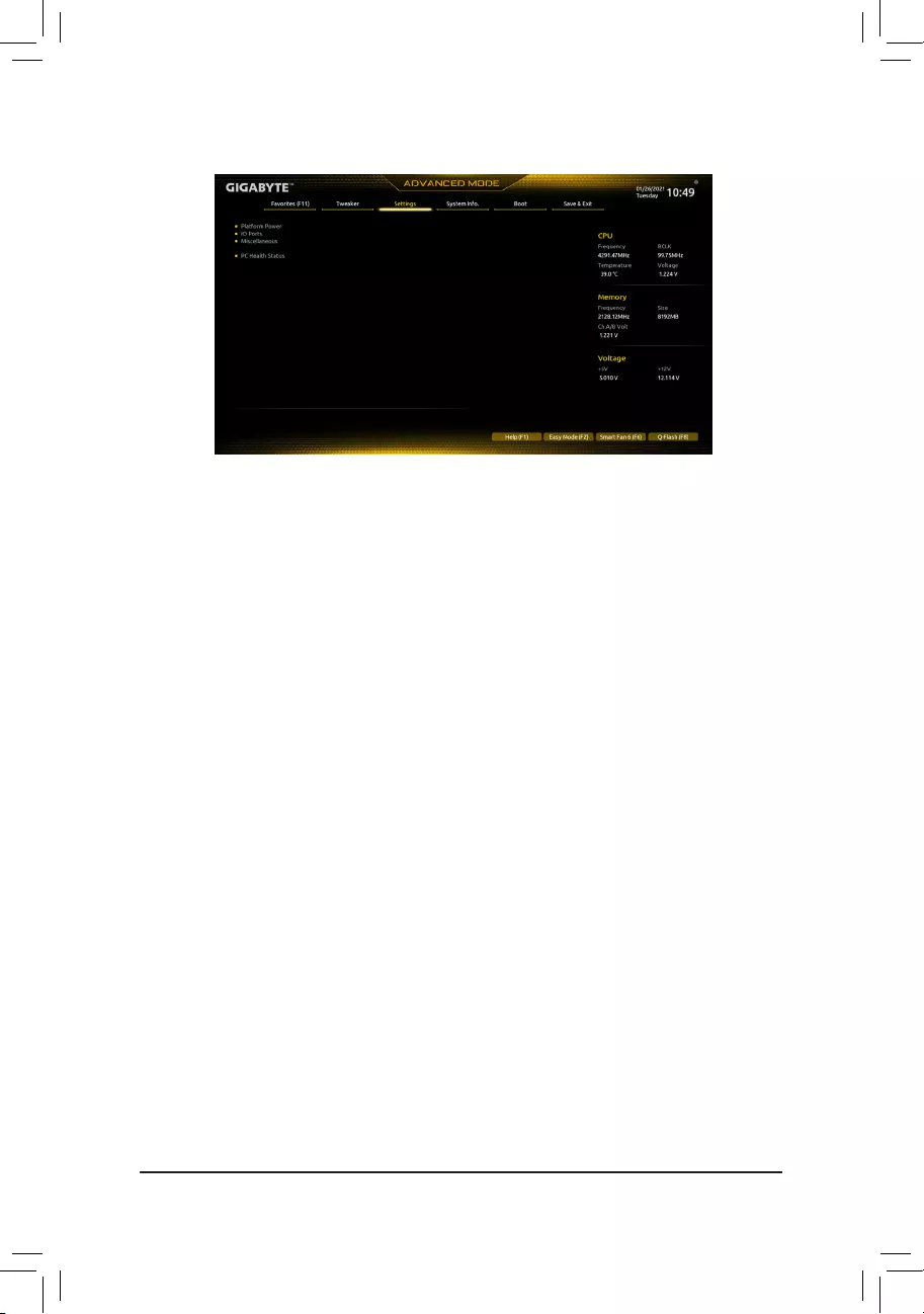
Platform Power
&Platform Power Management
Enables or disables the Active State Power Management function (ASPM). (Default: Disabled)
&PEG ASPM
Allows you to congure the ASPM mode for the device connected to the CPU PEG bus. This item is
congurable only when Platform Power Management is set to Enabled. (Default: Disabled)
&PCH ASPM
Allows you to congure the ASPM mode for the device connected to Chipset’s PCI Express bus. This item
is congurable only when Platform Power Management is set to Enabled. (Default: Disabled)
&DMI ASPM
Allows you to congure the ASPM mode for both CPU side and Chipset side of the DMI link. This item is
congurable only when Platform Power Management is set to Enabled. (Default: Disabled)
&Power On By Keyboard
Allows the system to be turned on by a PS/2 keyboard wake-up event.
Note: To use this function, you need an ATX power supply providing at least 1A on the +5VSB lead.
Disabled Disables this function. (Default)
Password Set a password with 1~5 characters to turn on the system.
Keyboard 98 Press POWER button on the Windows 98 keyboard to turn on the system.
Any Key Press any key to turn on the system.
&Power On Password
Set the password when Power On By Keyboard is set to Password.
Press <Enter> on this item and set a password with up to 5 characters and then press <Enter> to accept.
To turn on the system, enter the password and press <Enter>.
Note: To cancel the password, press <Enter> on this item. When prompted for the password, press <Enter>
again without entering the password to clear the password settings.
&Power On By Mouse
Allows the system to be turned on by a PS/2 mouse wake-up event.
Note: To use this function, you need an ATX power supply providing at least 1A on the +5VSB lead.
Disabled Disables this function. (Default)
Move Move the mouse to turn on the system.
Double Click Double click on left button on the mouse to turn on the system.
2-6 Settings
— 29 —

&ErP
Determines whether to let the system consume least power in S5 (shutdown) state. (Default: Disabled)
Note: When this item is set to Enabled, the following functions will become unavailable: Resume by Alarm,
power on by mouse, and power on by keyboard.
&Soft-Off by PWR-BTTN
Congures the way to turn off the computer in MS-DOS mode using the power button.
Instant-Off Press the power button and then the system will be turned off instantly. (Default)
Delay 4 Sec. Press and hold the power button for 4 seconds to turn off the system. If the power
button is pressed for less than 4 seconds, the system will enter suspend mode.
&Resume by Alarm
Determines whether to power on the system at a desired time. (Default: Disabled)
If enabled, set the date and time as following:
Wake up day: Turn on the system at a specic time on each day or on a specic day in a month.
Wake up hour/minute/second: Set the time at which the system will be powered on automatically.
Note: When using this function, avoid inadequate shutdown from the operating system or removal of the
AC power, or the settings may not be effective.
&Power Loading
Enables or disables dummy load. When the power supply is at low load, a self-protection will activate causing
it to shutdown or fail. If this occurs, please set to Enabled. Auto lets the BIOS automatically congure this
setting. (Default: Auto)
&RC6(Render Standby)
Allows you to determine whether to let the onboard graphics enter standby mode to decrease power
consumption. (Default: Enabled)
&AC BACK
Determines the state of the system after the return of power from an AC power loss.
Memory The system returns to its last known awake state upon the return of the AC power.
Always On The system is turned on upon the return of the AC power.
Always Off The system stays off upon the return of the AC power. (Default)
IO Ports
&Initial Display Output
Species the rst initiation of the monitor display from the installed PCI Express graphics card or the onboard
graphics.
IGFX (Note) Sets the onboard graphics as the rst display.
PCIe 1 Slot Sets the graphics card on the PCIEX16 slot as the rst display. (Default)
This item is congurable only when CSM Support is set to Enabled.
&Internal Graphics
Enables or disables the onboard graphics function. (Default: Auto)
&DVMT Pre-Allocated
Allows you to set the onboard graphics memory size. (Default: 64M)
&DVMT Total Gfx Mem
Allows you to allocate the DVMT memory size of the onboard graphics. Options are: 128M, 256M, MAX.
(Default: 256M)
&Aperture Size
Allows you to set the maximum amount of system memory that can be allocated to the graphics card.
Options are: 128MB, 256MB, 512MB, 1024MB, and 2048MB. (Default: 256MB)
(Note) This item is present only when you install a CPU that supports this feature.
— 30 —

&OnBoard LAN Controller
Enables or disables the onboard LAN function. (Default: Enabled)
If you wish to install a 3rd party add-in network card instead of using the onboard LAN, set this item to
Disabled.
&Audio Controller
Enables or disables the onboard audio function. (Default: Enabled)
If you wish to install a 3rd party add-in audio card instead of using the onboard audio, set this item to
Disabled.
&Above 4G Decoding
Enables or disables 64-bit capable devices to be decoded in above 4 GB address space (only if your system
supports 64-bit PCI decoding). Set to Enabled if more than one advanced graphics card are installed and
their drivers are not able to be launched when entering the operating system (because of the limited 4 GB
memory address space). (Default: Disabled)
&IOAPIC 24-119 Entries
Enables or disables this function. (Default: Enabled)
SuperIOConguration
&Serial Port
Enables or disables the onboard serial port. (Default: Enabled)
USBConguration
&Legacy USB Support
Allows USB keyboard/mouse to be used in MS-DOS. (Default: Enabled)
&XHCI Hand-off
Determines whether to enable XHCI Hand-off feature for an operating system without XHCI Hand-off
support. (Default: Enabled)
&USB Mass Storage Driver Support
Enables or disables support for USB storage devices. (Default: Enabled)
&Mass Storage Devices
Displays a list of connected USB mass storage devices. This item appears only when a USB storage device
is installed.
NetworkStackConguration
&Network Stack
Disables or enables booting from the network to install a GPT format OS, such as installing the OS from
the Windows Deployment Services server. (Default: Disabled)
&IPv4 PXE Support
Enables or disables IPv4 PXE Support. This item is congurable only when Network Stack is enabled.
&IPv4 HTTP Support
Enables or disables HTTP boot support for IPv4. This item is congurable only when Network Stack is
enabled.
&IPv6 PXE Support
Enables or disables IPv6 PXE Support. This item is congurable only when Network Stack is enabled.
&IPv6 HTTP Support
Enables or disables HTTP boot support for IPv6. This item is congurable only when Network Stack is
enabled.
— 31 —

&PXE boot wait time
Allows you to congure how long to wait before you can press <Esc> to abort the PXE boot. This item is
congurable only when Network Stack is enabled. (Default: 0)
&Media detect count
Allows you to set the number of times to check the presence of media. This item is congurable only when
Network Stack is enabled. (Default: 1)
NVMeConguration
Displays information on your M.2 NVME PCIe SSD if installed.
SATAAndRSTConguration
&SATA Controller(s)
Enables or disables the integrated SATA controllers. (Default: Enabled)
&SATA Mode Selection
Species the operating mode of the integrated SATA controllers.
AHCI Congures the SATA controllers to AHCI mode. Advanced Host Controller Interface
(AHCI) is an interface specication that allows the storage driver to enable advanced
Serial ATA features such as Native Command Queuing and hot plug. (Default)
&Aggressive LPM Support
Enables or disables the power saving feature, ALPM (Aggressive Link Power Management), for the Chipset
SATA controllers. (Default: Disabled)
&Port 0/1/2/3
Enables or disables each SATA port. (Default: Enabled)
&SATA Port 0/1/2/3 DevSlp
Allows you to determine whether to let the connected SATA device go into sleep mode. (Default: Disabled)
&Hot plug
Enables or disable the hot plug capability for each SATA port. (Default: Disabled)
&ConguredaseSATA
Enables or disables support for external SATA devices.
Realtek PCIe GBE Family Controller
This sub-menu provides information on LAN conguration and related conguration options.
Miscellaneous
&LEDs in System Power On State
Allows you to enable or disable motherboard LED lighting when the system is on.
Off Disables the selected lighting mode when the system is on.
On Enables the selected lighting mode when the system is on. (Default)
&Intel Platform Trust Technology (PTT)
Enables or disables Intel® PTT Technology. (Default: Disabled)
&3DMark01 Enhancement
Allows you to determine whether to enhance some legacy benchmark performance. (Default: Disabled)
&CPU PCIe Link Speed
Allows you to set the operation mode of the CPU-controlled PCI Express slots to Gen 1, Gen 2, Gen 3, or
Gen 4 (Note). Actual operation mode is subject to the hardware specication of each slot. Auto lets the BIOS
automatically congure this setting. (Default: Auto)
(Note) This item is present only when you install a CPU that supports this feature.
— 32 —

&PCH PCIe Link Speed
Allows you to set the operation mode of the Chipset-controlled PCI Express slots to Gen 1, Gen 2, or
Gen 3. Actual operation mode is subject to the hardware specication of each slot. Auto lets the BIOS
automatically congure this setting. (Default: Auto)
&VT-d
Enables or disables Intel® Virtualization Technology for Directed I/O. (Default: Enabled)
Trusted Computing
Enables or disables Trusted Platform Module (TPM).
PC Health Status
&Reset Case Open Status
Disabled Keeps or clears the record of previous chassis intrusion status. (Default)
Enabled Clears the record of previous chassis intrusion status and the Case Open eld will
show «No» at next boot.
&Case Open
Displays the detection status of the chassis intrusion detection device attached to the motherboard CI
header. If the system chassis cover is removed, this eld will show «Yes», otherwise it will show «No». To
clear the chassis intrusion status record, set Reset Case Open Status to Enabled, save the settings to
the CMOS, and then restart your system.
& CPU Vcore/CPU VCCSA/DRAM Channel A/B Voltage/+3.3V/+5V/+12V/CPU VAXG
Displays the current system voltages.
— 33 —
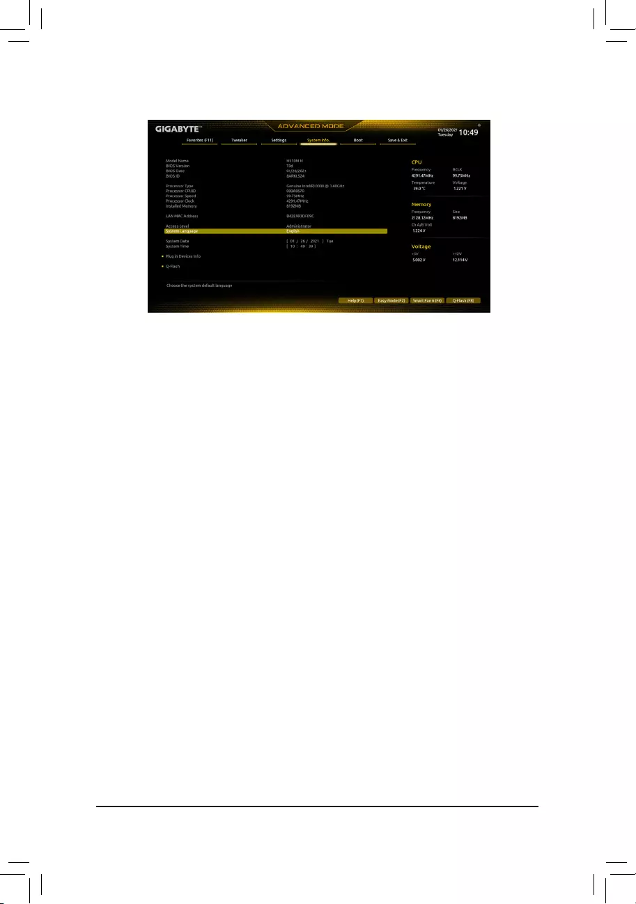
2-7 System Info.
This section provides information on your motherboard model and BIOS version. You can also select the default
language used by the BIOS and manually set the system time.
&Access Level
Displays the current access level depending on the type of password protection used. (If no password is
set, the default will display as Administrator.) The Administrator level allows you to make changes to all
BIOS settings; the User level only allows you to make changes to certain BIOS settings but not all.
&System Language
Selects the default language used by the BIOS.
&System Date
Sets the system date. The date format is week (read-only), month, date, and year. Use <Enter> to switch
between the Month, Date, and Year elds and use the <Page Up> or <Page Down> key to set the desired
value.
&System Time
Sets the system time. The time format is hour, minute, and second. For example, 1 p.m. is 13:00:00. Use
<Enter> to switch between the Hour, Minute, and Second elds and use the <Page Up> or <Page Down>
key to set the desired value.
Plug in Devices Info
Displays information on your PCI Express and M.2 devices if installed.
Q-Flash
Allows you to access the Q-Flash utility to update the BIOS or back up the current BIOS conguration.
— 34 —
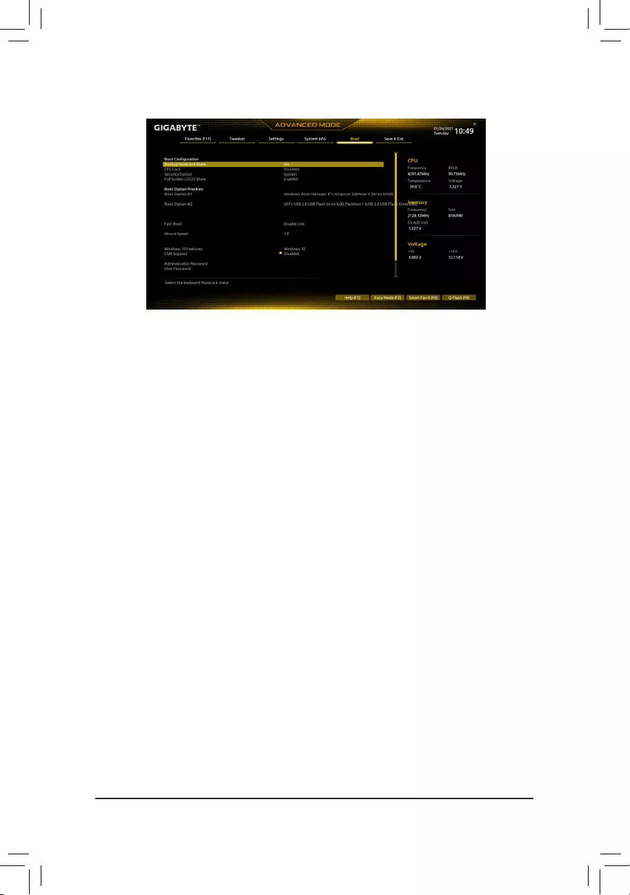
&Bootup NumLock State
Enables or disables Numlock feature on the numeric keypad of the keyboard after the POST. (Default: On)
&CFG Lock
Enables or disables the MSR 0xE2 function. (Default: Disabled)
&Security Option
Species whether a password is required every time the system boots, or only when you enter BIOS Setup.
After conguring this item, set the password(s) under the Administrator Password/User Password item.
Setup A password is only required for entering the BIOS Setup program.
System A password is required for booting the system and for entering the BIOS Setup program.
(Default)
&Full Screen LOGO Show
Allows you to determine whether to display the GIGABYTE Logo at system startup. Disabled skips the
GIGABYTE Logo when the system starts up. (Default: Enabled)
&Boot Option Priorities
Species the overall boot order from the available devices. Removable storage devices that support GPT
format will be prexed with «UEFI:» string on the boot device list. To boot from an operating system that
supports GPT partitioning, select the device prexed with «UEFI:» string.
Or if you want to install an operating system that supports GPT partitioning such as Windows 10 64-bit,
select the optical drive that contains the Windows 10 64-bit installation disc and is prexed with «UEFI:»
string.
&Fast Boot
Enables or disables Fast Boot to shorten the OS boot process. Ultra Fast provides the fastest bootup
speed. (Default: Disable Link)
&SATA Support
Last Boot SATA Devices Only Except for the previous boot drive, all SATA devices are disabled
before the OS boot process completes. (Default)
All SATA Devices All SATA devices are functional in the operating system and during the POST.
This item is congurable only when Fast Boot is set to Enabled or Ultra Fast.
2-8 Boot
— 35 —

&VGA Support
Allows you to select which type of operating system to boot.
Auto Enables legacy option ROM only.
EFI Driver Enables EFI option ROM. (Default)
This item is congurable only when Fast Boot is set to Enabled or Ultra Fast.
&USB Support
Disable Link All USB devices are disabled before the OS boot process completes.
Full Initial All USB devices are functional in the operating system and during the POST.
(Default)
Partial Initial Part of the USB devices are disabled before the OS boot process completes.
This item is congurable only when Fast Boot is set to Enabled or Ultra Fast. This function is disabled
when Fast Boot is set to Ultra Fast.
&PS2 Devices Support
Disable Link All PS/2 devices are disabled before the OS boot process completes.
Enabled All PS/2 devices are functional in the operating system and during the POST.
(Default)
This item is congurable only when Fast Boot is set to Enabled or Ultra Fast. This function is disabled
when Fast Boot is set to Ultra Fast.
&NetWork Stack Driver Support
Disable Link Disables booting from the network. (Default)
Enabled Enables booting from the network.
This item is congurable only when Fast Boot is set to Enabled or Ultra Fast.
&Next Boot After AC Power Loss
Normal Boot Enables normal bootup upon the return of the AC power. (Default)
Fast Boot Keeps the Fast Boot settings upon the return of the AC power.
This item is congurable only when Fast Boot is set to Enabled or Ultra Fast.
&Mouse Speed
Allows you to set the mouse cursor movement speed. (Default: 1 X)
&Windows 10 Features
Allows you to select the operating system to be installed. (Default: Windows 10)
&CSM Support
Enables or disables UEFI CSM (Compatibility Support Module) to support a legacy PC boot process.
Disabled Disables UEFI CSM and supports UEFI BIOS boot process only. (Default)
Enabled Enables UEFI CSM.
&LAN PXE Boot Option ROM
Allows you to select whether to enable the legacy option ROM for the LAN controller. (Default: Disabled)
This item is congurable only when CSM Support is set to Enabled.
&Storage Boot Option Control
Allows you to select whether to enable the UEFI or legacy option ROM for the storage device controller.
Do not launch Disables option ROM.
UEFI Enables UEFI option ROM only.
Legacy Enables legacy option ROM only. (Default)
This item is congurable only when CSM Support is set to Enabled.
— 36 —

&Other PCI devices
Allows you to select whether to enable the UEFI or Legacy option ROM for the PCI device controller other
than the LAN, storage device, and graphics controllers.
Do not launch Disables option ROM.
UEFI Enables UEFI option ROM only. (Default)
Legacy Enables legacy option ROM only.
This item is congurable only when CSM Support is set to Enabled.
&Administrator Password
Allows you to congure an administrator password. Press <Enter> on this item, type the password, and
then press <Enter>. You will be requested to conrm the password. Type the password again and press
<Enter>. You must enter the administrator password (or user password) at system startup and when entering
BIOS Setup. Differing from the user password, the administrator password allows you to make changes to
all BIOS settings.
&User Password
Allows you to congure a user password. Press <Enter> on this item, type the password, and then press
<Enter>. You will be requested to conrm the password. Type the password again and press <Enter>.
You must enter the administrator password (or user password) at system startup and when entering BIOS
Setup. However, the user password only allows you to make changes to certain BIOS settings but not all.
To cancel the password, press <Enter> on the password item and when requested for the password, enter
the correct one rst. When prompted for a new password, press <Enter> without entering any password.
Press <Enter> again when prompted to conrm.
NOTE: Before setting the User Password, be sure to set the Administrator Password rst.
Secure Boot
Allows you to enable or disable Secure Boot and congure related settings. This item is congurable only
when CSM Support is set to Disabled.
&Preferred Operating Mode
Allows you to select whether to enter Easy mode or Advanced mode after entering BIOS Setup. Auto
enters the BIOS mode where it was last time. (Default: Auto)
— 37 —
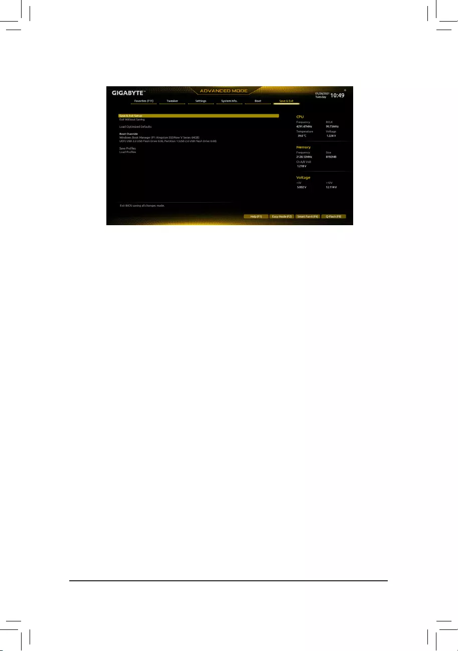
2-9 Save & Exit
&Save & Exit Setup
Press <Enter> on this item and select Yes. This saves the changes to the CMOS and exits the BIOS Setup
program. Select No or press <Esc> to return to the BIOS Setup Main Menu.
&Exit Without Saving
Press <Enter> on this item and select Yes. This exits the BIOS Setup without saving the changes made
in BIOS Setup to the CMOS. Select No or press <Esc> to return to the BIOS Setup Main Menu.
&Load Optimized Defaults
Press <Enter> on this item and select Yes to load the optimal BIOS default settings. The BIOS defaults
settings help the system to operate in optimum state. Always load the Optimized defaults after updating
the BIOS or after clearing the CMOS values.
&Boot Override
Allows you to select a device to boot immediately. Press <Enter> on the device you select and select Yes
to conrm. Your system will restart automatically and boot from that device.
&SaveProles
This function allows you to save the current BIOS settings to a prole. You can create up to 8 proles and
save as Setup Prole 1~ Setup Prole 8. Press <Enter> to complete. Or you can select Select File in
HDD/FDD/USB to save the prole to your storage device.
&LoadProles
If your system becomes unstable and you have loaded the BIOS default settings, you can use this function
to load the BIOS settings from a prole created before, without the hassles of reconguring the BIOS
settings. First select the prole you wish to load and then press <Enter> to complete. You can select Select
File in HDD/FDD/USB to input the prole previously created from your storage device or load the prole
automatically created by the BIOS, such as reverting the BIOS settings to the last settings that worked
properly (last known good record).
— 38 —
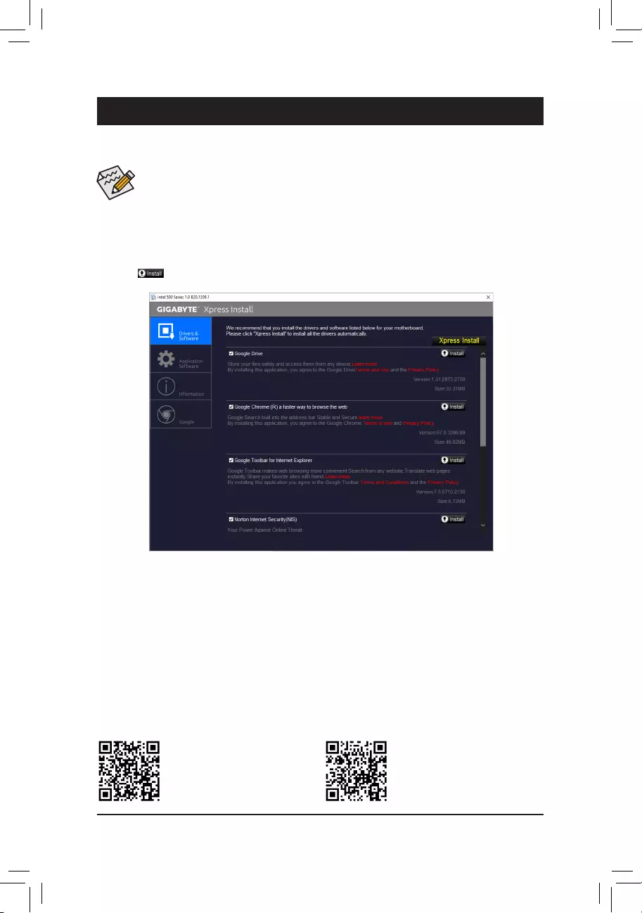
Chapter 3 Appendix
Please visit GIGABYTE’s website for
more software information.
Please visit GIGABYTE’s website for
more troubleshooting information.
•Before installing the drivers, rst install the operating system.
•After installing the operating system, insert the motherboard driver disc into your optical drive. Click
on the message «Tap to choose what happens with this disc» on the top-right corner of the screen
and select «Run Run.exe.» (Or go to My Computer, double-click the optical drive and execute the
Run.exe program.)
«Xpress Install» will automatically scan your system and then list all of the drivers that are recommended to
install. You can click the Xpress Install button and «Xpress Install» will install all of the selected drivers. Or click
the arrow icon to individually install the drivers you need.
Drivers Installation
— 39 —
Regulatory Notices
United States of America, Federal Communications Commission Statement
This equipment has been tested and found to comply with the limits for
a Class B digital device, pursuant to Part 15 of the FCC Rules. These
limits are designed to provide reasonable protection against harmful
interference in a residential installation. This equipment generates,
uses and can radiate radio frequency energy and, if not installed
and used in accordance with manufacturer’s instructions, may cause
harmful interference to radio communications. However, there is no
guarantee that interference will not occur in a particular installation. If
this equipment does cause harmful interference to radio or television
reception, which can be determined by turning the equipment off and
on, the user is encouraged to try to correct the interference by one or
more of the following measures:
•Reorient or relocate the receiving antenna.
•Increase the separation between the equipment and receiver.
•Connect the equipment to an outlet on a circuit different from that to
which the receiver is connected.
•Consult the dealer or an experienced radio/TV technician for help.
Canadian Department of Communications Statement
This digital apparatus does not exceed the Class B limits for radio
noise emissions from digital apparatus set out in the Radio Interference
Regulations of the Canadian Department of Communications. This class
B digital apparatus complies with Canadian ICES-003.
Avis de conformité à la réglementation d’Industrie Canada
Cet appareil numérique de la classe B est conforme à la norme NMB-
003 du Canada.
European Union (EU) CE Declaration of Conformity
This device complies with the following directives: Electromagnetic
Compatibility Directive 2014/30/EU, Low-voltage Directive 2014/35/
EU, RoHS directive (recast) 2011/65/EU & the 2015/863 Statement.
This product has been tested and found to comply with all essential
requirements of the Directives.
European Union (EU) RoHS (recast) Directive 2011/65/EU & the
European Commission Delegated Directive (EU) 2015/863 Statement
GIGABYTE products have not intended to add and safe from hazardous
substances (Cd, Pb, Hg, Cr+6, PBDE, PBB, DEHP, BBP, DBP and DIBP).
The parts and components have been carefully selected to meet RoHS
requirement. Moreover, we at GIGABYTE are continuing our efforts to
develop products that do not use internationally banned toxic chemicals.
European Union (EU) Community Waste Electrical & Electronic
Equipment (WEEE) Directive Statement
GIGABYTE will fulll the national laws as interpreted from the 2012/19/
EU WEEE (Waste Electrical and Electronic Equipment) (recast) directive.
The WEEE Directive species the treatment, collection, recycling and
disposal of electric and electronic devices and their components. Under
the Directive, used equipment must be marked, collected separately,
and disposed of properly.
WEEE Symbol Statement
The symbol shown below is on the product or on its
packaging, which indicates that this product must not be
disposed of with other waste. Instead, the device should
be taken to the waste collection centers for activation of
the treatment, collection, recycling and disposal procedure.
For more information about where you can drop off your waste equipment
for recycling, please contact your local government ofce, your household
waste disposal service or where you purchased the product for details
of environmentally safe recycling.
End of Life Directives-Recycling
The symbol shown below is on the product or on its
packaging, which indicates that this product must not be
disposed of with other waste. Instead, the device should
be taken to the waste collection centers for activation of the
treatment, collection, recycling and disposal procedure.
Déclaration de Conformité aux Directives de l’Union européenne (UE)
Cet appareil portant la marque CE est conforme aux directives de
l’UE suivantes: directive Compatibilité Electromagnétique 2014/30/
UE, directive Basse Tension 2014/35/UE et directive RoHS II 2011/65/
UE. La conformité à ces directives est évaluée sur la base des normes
européennes harmonisées applicables.
European Union (EU) CE-Konformitätserklärung
Dieses Produkte mit CE-Kennzeichnung erfüllen folgenden EU-
Richtlinien: EMV-Richtlinie 2014/30/EU, Niederspannungsrichtlinie
2014/30/EU und RoHS-Richtlinie 2011/65/EU erfüllt. Die Konformität mit
diesen Richtlinien wird unter Verwendung der entsprechenden Standards
zurEuropäischen Normierung beurteilt.
CE declaração de conformidade
Este produto com a marcação CE estão em conformidade com das
seguintes Diretivas UE: Diretiva Baixa Tensão 2014/35/EU; Diretiva
CEM 2014/30/EU; Diretiva RSP 2011/65/UE. A conformidade com estas
diretivas é vericada utilizando as normas europeias harmonizadas.
CE Declaración de conformidad
Este producto que llevan la marca CE cumplen con las siguientes
Directivas de la Unión Europea: Directiva EMC (2014/30/EU), Directiva
de bajo voltaje (2014/35/EU), Directiva RoHS (recast) (2011/65/EU).
El cumplimiento de estas directivas se evalúa mediante las normas
europeas armonizadas.
Dichiarazione di conformità CE
Questo prodotto è conforme alle seguenti direttive: Direttiva sulla
compatibilità elettromagnetica 2014/30/UE, Direttiva sulla bassa tensione
2014/35/UE, Direttiva RoHS (rifusione) 2011/65/UE. Questo prodotto è
stato testato e trovato conforme a tutti i requisiti essenziali delle Direttive.
Supplier’s Declaration of Conformity
47 CFR § 2.1077 Compliance Information
Product Name: Motherboard
Trade Name: GIGABYTE
Model Number: H510M H
Responsible Party – U.S. Contact Information: G.B.T. Inc.
Address: 17358 Railroad street, City Of Industry, CA91748
Tel.: 1-626-854-9338
Internet contact information: https://www.gigabyte.com
FCC Compliance Statement:
This device complies with Part 15 of the FCC Rules, Subpart B, Unintentional Radiators.
Operation is subject to the following two conditions: (1) This device may not cause harmful interference, and (2) this
device must accept any interference received, including interference that may cause undesired operation.
— 40 —
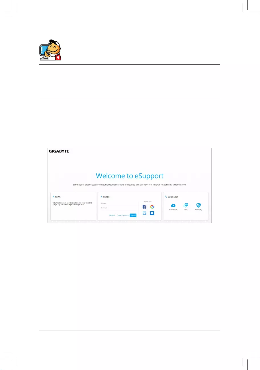
Contact Us
GIGA-BYTE TECHNOLOGY CO., LTD.
Address: No.6, Baoqiang Rd., Xindian Dist., New Taipei City 231, Taiwan
TEL: +886-2-8912-4000, FAX: +886-2-8912-4005
Tech. and Non-Tech. Support (Sales/Marketing) : https://esupport.gigabyte.com
WEB address (English): https://www.gigabyte.com
WEB address (Chinese): https://www.gigabyte.com/tw
•GIGABYTE eSupport
To submit a technical or non-technical (Sales/Marketing) question, please link to:
https://esupport.gigabyte.com
— 41 —
- Manuals
- Brands
- Gigabyte Manuals
- Motherboard
- H510M H