- Manuals
- Brands
- Gigabyte Manuals
- Motherboard
- Z370 HD3
- User manual
-
Contents
-
Table of Contents
-
Bookmarks
Quick Links
Z370 HD3
User’s Manual
Rev. 1001
12ME-Z370HD3-1001R
For more product details, please visit GIGABYTE’s website.
To reduce the impacts on global warming, the packaging materials of this product
are recyclable and reusable. GIGABYTE works with you to protect the environment.
Related Manuals for Gigabyte Z370 HD3
Summary of Contents for Gigabyte Z370 HD3
-
Page 1
Z370 HD3 User’s Manual Rev. 1001 12ME-Z370HD3-1001R For more product details, please visit GIGABYTE’s website. To reduce the impacts on global warming, the packaging materials of this product are recyclable and reusable. GIGABYTE works with you to protect the environment. -
Page 2
The trademarks mentioned in this manual are legally registered to their respective owners. Disclaimer Information in this manual is protected by copyright laws and is the property of GIGABYTE. No part of this manual may be reproduced, copied, translated, transmitted, or published in any form or by any means without GIGABYTE’s prior written permission. -
Page 3: Table Of Contents
Table of Contents Z370 HD3 Motherboard Layout ………………4 Chapter 1 Hardware Installation ………………5 Installation Precautions ………………5 ………………6 Installing the CPU ……………….. 9 Installing the Memory ………………9 Installing an Expansion Card …………….. 10 Back Panel Connectors ……………… 10 Internal Connectors ………………
-
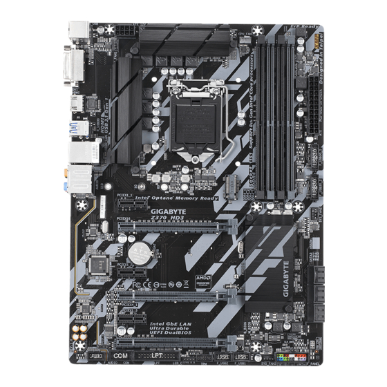
Page 4: Z370 Hd3 Motherboard Layout
Z370 HD3 Motherboard Layout ATX_12V_2X4 KB_MS_USB CPU_FAN SYS_FAN1 LGA1151 USB30_LAN AUDIO PCIEX1_1 Z370 HD3 PCIEX16 Intel ® Intel Z370 ® ® Super I/O PCIEX1_2 PCIEX4_1 CODEC PCIEX1_3 PCIEX4_2 B_BIOS M_BIOS SPDIF_O F_AUDIO LED_C F_USB2 SYS_FAN3 F_PANEL F_USB1 VGA BOOT Box Contents…
-
Page 5: Chapter 1 Hardware Installation
Chapter 1 Hardware Installation Installation Precautions The motherboard contains numerous delicate electronic circuits and components which can become damaged as a result of electrostatic discharge (ESD). Prior to installation, carefully read the user’s manual and follow these procedures: Prior to installation, make sure the chassis is suitable for the motherboard. Prior to installation, do not remove or break motherboard S/N (Serial Number) sticker or warranty sticker provided by your dealer.
-
Page 6
Chipset Intel ® Z370 Express Chipset Memory Dual channel memory architecture non-ECC mode) (Go to GIGABYTE’s website for the latest supported memory speeds and memory modules.) ® Onboard Integrated Graphics Processor-Intel HD Graphics support: Graphics * The DVI-D port does not support D-Sub connection by adapter. -
Page 7
Internal 1 x 24-pin ATX main power connector Connectors 1 x 8-pin ATX 12V power connector 1 x CPU fan header 3 x system fan headers 6 x SATA 6Gb/s connectors 1 x M.2 Socket 3 connector 1 x front panel header 1 x front panel audio header 1 x S/PDIF Out header 2 x USB 3.1 Gen 1 headers… -
Page 8
ATX Form Factor; 30.5cm x 22.5cm prior notice. Please visit GIGABYTE’s website Please visit the SupportUtility List for support lists of CPU, memory page on GIGABYTE’s website to modules, SSDs, and M.2 devices. download the latest version of apps. — 8 -… -
Page 9: Installing The Cpu
Make sure that the motherboard supports the memory. It is recommended that memory of the same capacity, brand, speed, and chips be used. (Go to GIGABYTE’s website for the latest supported memory speeds and memory modules.) Always turn off the computer and unplug the power cord from the power outlet before installing the memory to prevent hardware damage.
-
Page 10: Installing An Expansion Card
The four memory sockets are divided into two channels and each channel has two memory sockets as following: 2 Modules DS/SS DS/SS DS/SS DS/SS 4 Modules DS/SS DS/SS DS/SS DS/SS Due to CPU limitations, read the following guidelines before installing the memory in Dual Channel mode. Dual Channel mode cannot be enabled if only one memory module is installed.
-
Page 11
Mic In (Pink) The Mic in jack. Please visit GIGABYTE’s website for more audio software information. device and then remove it from the motherboard. When removing the cable, pull it straight out from the connector. Do not rock it side to side to prevent an electrical short inside the cable connector. -
Page 12: Internal Connectors
Internal Connectors 8 18 ATX_12V_2X4 CPU_FAN First make sure your devices are compliant with the connectors you wish to connect. Before installing the devices, be sure to turn off the devices and your computer. Unplug the power cord from the power outlet to prevent damage to the devices. After installing the device and before turning on the computer, make sure the device cable has been securely attached to the connector on the motherboard.
-
Page 13
With the use of the power connector, the power supply can supply enough stable power to all the components off and all devices are properly installed. The power connector possesses a foolproof design. Connect the power supply cable to the power connector in the correct orientation. The 12V power connector mainly supplies power to the CPU. -
Page 14
rating of 2A (12V) and maximum length of 2m. Pin No. triangle on the plug) of the LED strip must be connected to Pin 1 (12V) of LED Strip this header. Incorrect connection may lead to the damage of the LED strip. Before installing the devices, be sure to turn off the devices and your computer. -
Page 15
Follow the steps below to correctly install an M.2 SSD in the M.2 connector. Step 1: Use a screw driver to unfasten the screw and nut from the motherboard. Locate the proper mounting hole Step 2: Slide the M.2 SSD into the connector at an angle. Step 3: Press the M.2 SSD down and then secure it with the screw. -
Page 16
Connect the power switch, reset switch, speaker, chassis intrusion switch/sensor and system status indicator on the chassis to this header according to the pin assignments below. Note the positive and negative pins before connecting the cables. (Power LED, Yellow/Purple): Power LED Power Switch Speaker Connects to the power status indicator… -
Page 17
This header supports digital S/PDIF Out and connects a S/PDIF digital audio cable (provided by expansion cards) for digital audio output from your motherboard to certain expansion cards like graphics cards and sound cards. For example, some graphics cards may require you to use a S/PDIF digital audio cable for digital audio output from your motherboard to your graphics card if you wish to connect an HDMI display to the graphics card and have digital audio output from the HDMI display at the same time. -
Page 18
13) LPT (Parallel Port Header) The LPT header can provide one parallel port via an optional LPT port cable. For purchasing the optional LPT port cable, please contact the local dealer. Pin No. Pin No. Pin No. STB- ACK- AFD- BUSY INIT- No Pin… -
Page 19
the CMOS values, use a metal object like a screwdriver to touch the two pins for a few seconds. Open: Normal Short: Clear CMOS Values Always turn off your computer and unplug the power cord from the power outlet before clearing the CMOS values. -
Page 20: Chapter 2 Bios Setup
To access the BIOS Setup program, press the <Delete> key during the POST when the power is turned on. To upgrade the BIOS, use either the GIGABYTE Q-Flash or @BIOS utility. Q-Flash allows the user to quickly and easily upgrade or back up BIOS without entering the operating system.
-
Page 21
Whether the system will work stably with the overclock/overvoltage settings you made is dependent on your overall and reduce the useful life of these components. This page is for advanced users only and we recommend you not to alter the default settings to prevent system instability or other unexpected results. (Inadequately altering the settings may result in system’s failure to boot. -
Page 22
The settings above are synchronous to those under the same items on the menu. (Note) AVX offset is the negative offset of AVX ratio. Uncore Ratio Allows you to set the CPU Uncore ratio. The adjustable range is dependent on the CPU being used. Uncore Frequency Displays the current CPU Uncore frequency. -
Page 23
C3 State Support (Note) Allows you to determine whether to let the CPU enter C3 mode in system halt state. When enabled, the CPU core frequency and voltage will be reduced during system halt state to decrease power consumption. The C3 state is a more enhanced power-saving state than C1. Auto this setting. -
Page 24
(Note) Allows the BIOS to read the SPD data on XMP memory module(s) to enhance memory performance when enabled. Disabled Disables this function. (Default) (Note) System Memory Multiplier Allows you to set the system memory multiplier. Auto sets memory multiplier according to memory SPD data. -
Page 25
Memory Multiplier Tweaker Provides different levels of memory auto-tuning. (Default: Auto) Enables or disables memory channel interleaving. allows the system to simultaneously access different channels of the memory to increase memory performance and stability. Auto lets the BIOS Enables or disables memory rank interleaving. allows the system to simultaneously access different ranks of the memory to increase memory performance and stability. -
Page 26
Displays the current system voltages. Max Link Speed Allows you to set the operation mode of the PCI Express slots to Gen 1, Gen 2, or Gen 3. Actual operation Auto setting. (Default: Auto) Allows you to determine whether to enhance some legacy benchmark performance. (Default: Disabled) Monitor Allows you to select a target to monitor and to make further adjustment. -
Page 27: System
System This section provides information on your motherboard model and BIOS version. You can also select the default language used by the BIOS and manually set the system time. Access Level Displays the current access level depending on the type of password protection used. (If no password is set, the default will display as Administrator.) The Administrator level allows you to make changes to all BIOS settings;…
-
Page 28
A password is required for booting the system and for entering the BIOS Setup program. (Default) Allows you to determine whether to display the GIGABYTE Logo at system startup. Disabled skips the GIGABYTE Logo when the system starts up. (Default: Enabled) Or if you want to install an operating system that supports GPT partitioning such as Windows 10 64-bit, string. -
Page 29
SATA Support Last Boot HDD Only Except for the previous boot drive, all SATA devices are disabled before the OS boot process completes. All Sata Devices All SATA devices are functional in the operating system and during the POST. (Default) Fast Boot is set to or Ultra Fast. -
Page 30
than the LAN, storage device, and graphics controllers. CSM Support is set to Administrator Password <Enter>. You must enter the administrator password (or user password) at system startup and when entering BIOS Setup. Differing from the user password, the administrator password allows you to make changes to all BIOS settings. -
Page 31: Peripherals
Peripherals graphics. Enables or disables 64-bit capable devices to be decoded in above 4 GB address space (only if your system supports 64-bit PCI decoding). Set to Enabled if more than one advanced graphics card are installed and their drivers are not able to be launched when entering the operating system (because of the limited 4 GB memory address space).
-
Page 32
Displays information on your M.2 PCIe SSD if installed. Enables or disables Trusted Platform Module (TPM). Serial Port Enables or disables the onboard serial port. (Default: Enabled) Parallel Port Enables or disables the onboard parallel port. (Default: Enabled) ® Enables or disables the Intel BIOS Guard feature, which protects the BIOS from malicious attacks. -
Page 33
Allows USB keyboard/mouse to be used in MS-DOS. (Default: Enabled) XHCI Hand-off Determines whether to enable XHCI Hand-off feature for an operating system without XHCI Hand-off support. (Default: Disabled) Enables or disables support for USB storage devices. (Default: Enabled) Enables or disables emulation of I/O ports 64h and 60h. This should be enabled for full legacy support for USB keyboards/mice in MS-DOS or in operating system that does not natively support USB devices. -
Page 34: Chipset
Chipset VT-d (Note) ® Enables or disables Intel Enables or disables the onboard graphics function. (Default: Auto) DVMT Pre-Allocated (Default: 256M) Audio Controller Enables or disables the onboard audio function. (Default: Enabled) If you wish to install a 3rd party add-in audio card instead of using the onboard audio, set this item to Disabled.
-
Page 35: Power
Power Enables or disables the Active State Power Management function (ASPM). (Default: Disabled) is set to . (Default: Enabled) PCH ASPM is set to . (Default: Enabled) DMI ASPM is set to . (Default: Enabled) Determines the state of the system after the return of power from an AC power loss. Memory The system returns to its last known awake state upon the return of the AC power.
-
Page 36
Set the password when is set to Password. Press <Enter> on this item and set a password with up to 5 characters and then press <Enter> to accept. To turn on the system, enter the password and press <Enter>. Note: To cancel the password, press <Enter> on this item. When prompted for the password, press <Enter> again without entering the password to clear the password settings. -
Page 37: Save & Exit
Press <Enter> on this item and select Yes. This saves the changes to the CMOS and exits the BIOS Setup program. Select No or press <Esc> to return to the BIOS Setup Main Menu. Press <Enter> on this item and select Yes. This exits the BIOS Setup without saving the changes made in BIOS Setup to the CMOS.
-
Page 38: Chapter 3 Appendix
Chapter 3 Appendix RAID Levels RAID 0 RAID 1 RAID 5 RAID 10 Minimum Number of Hard Drives Array Capacity Number of hard (Number of hard (Number of hard drive smallest drive the smallest drive smallest drive Fault Tolerance (Note 1) At least two SATA hard drives or SSDs.
-
Page 39
Steps: 1. In BIOS Setup, go to and set CSM Support to Disabled. Save the changes and exit BIOS Setup. 2. After the system reboot, enter BIOS Setup again. Then enter the sub-menu. 3. On the menu, press <Enter> on Create RAID Volume to enter the Create RAID Volume under the Name drives being installed). -
Page 40: Installing An Intel ® Optane ™ Memory
With the correct BIOS settings, you are ready to install the operating system. ® As some operating systems already include Intel performance and compatibility. If the operating system to be installed requires that you provide additional SATA 1. Copy the IRST folder under Boot in the driver disk to your USB thumb drive. 2.
-
Page 41: Drivers Installation
After installing the operating system, insert the motherboard driver disk into your optical drive. Click install. You can click the Xpress Install the arrow icon to individually install the drivers you need. Please visit GIGABYTE’s website for Please visit GIGABYTE’s website more software information. software.
-
Page 42
Contravention will be prosecuted. We believe that the information contained herein was accurate in all respects at the time of printing. GIGABYTE cannot, however, assume any responsibility for errors or omissions in this text. Also note that the information in this document is subject to change without notice and should not be construed as a commitment by GIGABYTE. -
Page 43
This equipment has been tested and found to comply with the limits for a Class B digital device, pursuant to Part in a residential installation. This equipment generates, uses, and can radiate radio frequency energy and, if not installed and used in accordance with the instructions, may cause harmful interference to radio communications. However, there is no guarantee that interference will not occur in a particular installation. -
Page 44: Contact Us
Contact Us TEL: +886-2-8912-4000, FAX: +886-2-8912-4005 Tech. and Non-Tech. Support (Sales/Marketing) : http://esupport.gigabyte.com WEB address (English): http://www.gigabyte.com WEB address (Chinese): http://www.gigabyte.tw To submit a technical or non-technical (Sales/Marketing) question, please link to: http://esupport.gigabyte.com — 44 -…
Инструкцию для GIGABYTE Z370 HD3P на русском языке, в формате pdf можно скачать с нашего сайта. Наш каталог предоставляем Вам инструкцию производителя фирмы GIGABYTE, которая была взята из открытых источников. Ознакомившись с руководством по эксплуатации от GIGABYTE, Вы на все 100% и правильно сможете воспользоваться всеми функциями устройства.
Для сохранения инструкции «Материнская плата GIGABYTE Z370 HD3P» на русском языке на вашем компьютере либо телефоне, нажмите кнопку «Скачать инструкцию». Если активна кнопка «Инструкция онлайн», то Вы можете просмотреть документ (manual), в своём браузере онлайн.
Если у Вас нет возможности скачать инструкцию по эксплуатации либо просмотреть её, Вы можете поделиться ссылкой на эту страницу в социальных сетях и при удобном моменте скачать инструкцию. Либо добавьте эту страницу в закладки Вашего браузера, нажав кнопку «Добавить страницу в закладки браузера».
-
Драйверы
16
-
Инструкции по эксплуатации
5
Языки:

Gigabyte Z370 HD3 инструкция по эксплуатации
(44 страницы)
- Языки:Английский
-
Тип:
PDF -
Размер:
11.78 MB
Просмотр

Gigabyte Z370 HD3 инструкция по эксплуатации
(48 страниц)
- Языки:Китайский
-
Тип:
PDF -
Размер:
12.54 MB
Просмотр

Gigabyte Z370 HD3 инструкция по эксплуатации
(44 страницы)
- Языки:Корейский
-
Тип:
PDF -
Размер:
11.76 MB
Просмотр

Gigabyte Z370 HD3 инструкция по эксплуатации
(44 страницы)
- Языки:Японский
-
Тип:
PDF -
Размер:
11.95 MB
Просмотр

Gigabyte Z370 HD3 инструкция по эксплуатации
(48 страниц)
- Языки:Китайский
-
Тип:
PDF -
Размер:
12.74 MB
Просмотр
На NoDevice можно скачать инструкцию по эксплуатации для Gigabyte Z370 HD3. Руководство пользователя необходимо для ознакомления с правилами установки и эксплуатации Gigabyte Z370 HD3. Инструкции по использованию помогут правильно настроить Gigabyte Z370 HD3, исправить ошибки и выявить неполадки.
X
You may only add up to 5 items for comparison at one time.
Закрыть


инструкцияGigabyte Z370 HD3-OP

To reduce the impacts on global warming, the packaging materials of this product
are recyclable and reusable. GIGABYTE works with you to protect the environment.
For more product details, please visit GIGABYTE’s website.
Z370 HD3
User’s Manual
Rev. 1001
12ME-Z37H3OP-1001R
Посмотреть инструкция для Gigabyte Z370 HD3-OP бесплатно. Руководство относится к категории материнские платы, 1 человек(а) дали ему среднюю оценку 7.3. Руководство доступно на следующих языках: английский. У вас есть вопрос о Gigabyte Z370 HD3-OP или вам нужна помощь? Задайте свой вопрос здесь
- Z370 HD3 Motherboard Layout
- Chapter 1 Hardware Installation
- Chapter 2 BIOS Setup
- Chapter 3 Appendix

Главная
Память
| Поддерживаемые типы памяти | DDR4-SDRAM |
| Тип слотов памяти | DIMM |
| Количество слотов памяти | 4 |
| Каналы памяти | Dual-channel |
| Error-correcting code (ECC) | Да |
| без функции коррекции ошибок | Да |
| Поддерживаемые частоты памяти | 2133,2400,2666,2800,3000,3200,3300,3333,3400,3466,3600,3666,3733,3800,3866,4000 MHz |
| Максимальная внутренняя память | 64 GB |
| Небуферизованная память | Да |
Особые свойства процессора
| экстремальный профиль памяти Intel | Да |
| Intel® Optane™ Memory Ready | Да |
| Установлен модуль Intel® Optane™ Memory | Да |
Свойства
| Поддерживаемые операционные системы Windows | Windows 10 Education x64, Windows 10 Enterprise x64, Windows 10 Home x64, Windows 10 Pro x64 |
| Комплектующие для | ПК |
| Семейство чипсета материнской платы | Intel |
| Чипсет материнской платы | Intel® Z370 Express |
| Формат материнской платы | ATX |
| Выходные звуковые каналы | 7.1 канала |
| Аудио чип | Realtek ALC892 |
| Мониторинг состояния ПК | FAN, Temperature, Voltage |
| Тип источника питания | ATX |
Графический адаптер
| Поддержка технологии параллельной обработки | Crossfire |
| HDCP | Да |
| Семейство графического адаптера | Intel |
| Максимальное разрешение | 4096 x 2160 пикселей |
Процессор
| Производитель процессора | Intel |
| Совместимые серии процессоров | Intel Core i3, Intel Core i5, Intel Core i7 |
| Сокет процессора | LGA 1151 (разъем H4) |
| Максимальное число процессоров для SMP | 1 |
Слоты расширения
| Слоты PCI Express x1 (поколение 3.x) | 3 |
| PCI Express x16 слоты | 3 |
| Количество M.2 (M) слотов | 1 |
Внутренние порты
| Разъемы USB 2.0 | 2 |
| Разъемы USB 3.2 Gen 1 (3.1 Gen 1) | 2 |
| Разъемы USB 3.2 Gen 2 (3.1 Gen 2) | 0 |
| Разъем выхода S/PDIF | Да |
| Разъем вентилятора центрального процессора | Да |
| Разъем питания ATX (24-конт.) | Да |
| Количество разъемов вентилятора корпуса | 3 |
| Аудиоразъем передней панели | Да |
| TPM коннектор | Да |
| Параллельный разъем | Да |
| Коннекторы последовательного порта | 1 |
| Разъем передней панели | Да |
| 12В разъем питания | Да |
| Количество параллельных разъемов ATA (PATA) | 0 |
| Количество разъемов SATA II | 0 |
| Количество разъемов SATA III | 6 |
BIOS
| Тип BIOS | UEFI AMI |
| Размер памяти BIOS | 32 Mbit |
| Перемычка Clear CMOS | Да |
| Plug & Play | Да |
| Desktop Management Interface (DMI) версия | 2.7 |
| Версия BIOS (SMBIOS) | 2.7 |
Порты на задней панели
| Количество портов USB 2.0 | 2 |
| Количество портов USB 3.2 Gen 1 (3.1 Gen 1) Type-A | 4 |
| Количество портов USB 3.2 Gen 1 (3.1 Gen 1) Type-С | 0 |
| Количество портов USB 3.2 Gen 2 (3.1 Gen 2) Type-A | 0 |
| Количество портов USB 3.2 Gen 2 (3.1 Gen 2) Type-С | 0 |
| Количество портов Ethernet LAN ( RJ-45) | 1 |
| Количество портов eSATA | 0 |
| Линейный вход микрофона | Да |
| Версия HDMI | 1.4 |
| Количество портов PS/2 | 1 |
| Порты FireWire | 0 |
| Количество портов VGA (D-Sub) | 0 |
| Количество портов DVI-D | 1 |
| Количество HDMI портов | 1 |
Сеть
| Подключение Ethernet | Да |
| Тип Ethernet интерфейса | Гигабитный Ethernet |
Вес и размеры
| Ширина | 305 mm |
| Глубина | 225 mm |
Контроллеры хранения данных
Содержимое упаковки
| Поставляемые кабели | SATA |
| Поставляемое ПО | Norton Internet Security, cFosSpeed |
| Драйвера в комплекте | Да |
| Инструкция | Да |
показать больше
Не можете найти ответ на свой вопрос в руководстве? Вы можете найти ответ на свой вопрос ниже, в разделе часто задаваемых вопросов о Gigabyte Z370 HD3-OP.
Какая ширина Gigabyte Z370 HD3-OP?
Какая толщина Gigabyte Z370 HD3-OP?
Инструкция Gigabyte Z370 HD3-OP доступно в русский?
Не нашли свой вопрос? Задайте свой вопрос здесь